

Page 1

2 1 9 0 0 1 8 2 1
Read this guide thoroughly. It contains important safety information.
Minimum age: Operator: 16 or older with a valid driver’s license. Keep this Operator’s Guide in the vehicle.
WARNING
2017
MAVERICK X3 Series
MAVERICK
TM
X3 Series
2017
Operator’s
Guide
Includes
Safety, Vehicle
and Maintenance Information
Original Instructions
Page 2
WARNING
YOUR VEHICLE CAN BE HAZARDOUS TO OPERATE. A collision or rollover
can occur quickly, if you fail to take proper precautions, even during routine
maneuvers such as turning and driving on hills or over obstacles.
For your safety, understand and follow all the warnings contained in this
Operator's Guide and on the labels on your vehicle. Failure to follow these
warnings can result in SEVERE INJURY OR DEATH!
Keep this Operator's Guide with the vehicle at all times.
WARNING
Disregarding any of the safety precautions and instructions contained in
this Operator's Guide,
SAFETY VIDEO
and on-product safety labels could
result in severe injury including the possibility of death!
WARNING
This vehicle may exceed the performance of other vehicles you may have
ridden in the past. Take time to familiarize yourself with your new vehicle.
CALIFORNIA PROPOSITION 65 WARNING
WARNING
This vehicle contains or emits chemicals known to the state of California to
cause cancer and birth defects or other reproductive harm.
In Canada, products are distributed by Bombardier Recreational Products Inc.
(BRP).
In USA, products are distributed by BRP US Inc.
The following trademarks are the property of Bombardier Recreational
Products Inc.:
Can-Am
D.E.S.S.™
®
DPS™ ROTAX
Maverick™ X™
This document contains the trademark of the following companies:
†
Visco-Lok is a trademark of GKN Viscodrive GmbH.
†
QS3 is a trademark of Fox Factory, Inc.
®
XPS™
219001821 en JT
®™ and the BRP logo are trademarks of Bombardier Recreational Products Inc. or its affiliates.
©2016 Bombardi
er Recreational Products Inc. and BRP US Inc. All rights reserved.
Page 3

FOREWORD
Dieses Handbuch ist m öglicherweise in Ihrer Landessprache
Deutsch
verfügbar. Bitte wenden Sie sich an Ihren Händler oder besuchen Sie:
www.operatorsguides.brp.com
English
Español
Français
日本語
Nederlands
Norsk
Português
Suomi
Svenska
This guide may be available in your language. Check with your dealer or
go to: www.operatorsguides.brp.com
Es posible que este manual esté disponible en s u idioma. Consulte a su
distribuidor o visite: www.operatorsguides.brp.com
Ce guide peut être disponible dans v otre langue. Vérifier avec votre
concessionnaire ou aller à: www.operatorsguides.brp.com
このガイドは、言語によって翻訳版が用意されています。.
ディーラーに問い合わせるか、次のアドレスでご確認ください:
www.operatorsguides.brp.com
Deze handleiding kan beschikbaar zijn in uw taal. Vraag het aan uw dealer
of ga naar: www.operatorsguides.brp.com
Denne boken kan finnes tilgjengelig på ditt eget språk. Kontakt din
forhandler eller gå til: www.operatorsguides.brp.com
Este manual pode estar disponível em seu idioma. Fale com sua
concessionária ou visite o site: www.operatorsguides.brp.com
Käyttöohjekirja voi olla saatavissa omalla kielelläsi. Tarkista jälleenmyyjältä
tai käy osoitteessa: www.operatorsguides.brp.com
Denna bok kan finnas tillgänglig på ditt språk. Kontakta din återförsäljare
eller gå till: www.operatorsguides.brp.com
Congratulations on your purchase of
a new Can-Am
®
side-by-side vehicle.
It's backed by the BRP limited warranty
and a network of authorized Can-Am
dealers ready to provide the parts, accessories or service you may require.
At delivery, you were informed of the
warranty coverage and signed the
PREDELIVERY C HECK LIST
to ensure
your new vehicle was prepared to your
entire satisfaction.
Your dealer is committed to your satisfaction. If you need more information,
please ask your dealer.
Know Before you Go
To learn how to reduce the risk of accident for you or bystanders, read this
Operator's Guide before you operate
the vehicle.
Also, read all safety labels on your vehicleandwatchthe
SAFETY VIDEO
.
Failure to follow the warnings contained in this Operator's Guide can
result in SERIOUS INJURY or DEATH.
Safety Messages
The types of safety messages, what
they look like and how they are used in
this guide are explained as follows:
The safety alert symbol
indicates
a potential injury hazard.
WARNING
Indicates a potential hazar
if not avoided, could result in serious injury or death.
dwhich,
_______________
1
Page 4

FOREWORD
CAUTION Indicates a haz-
ardous situation which, if not
avoided, could result in minor or
moderate injury.
NOTICE
which, if not followed, could result
in severely damaged vehicle components or other property.
Indicates an instruction
About this Operator's
Guide
This Operator's Guide has been prepared to acquaint the owner/operator
of a new vehicle with the various vehicle controls, maintenance and safe
operating instructions. It is indispensable for the proper use of the product.
Keep this Operator's Guide in the vehicle as you can refer to it for things such
as maintenance, troubleshooting and
instructing others.
Note that this guid e is available in several languages. In the event of any discrepancy, the E nglish version shall prevail.
Ifyouwanttoviewand/orprintan
extra copy of your Operator's Guide,
simply visit the following website
www.operatorsguides.brp.com.
The information contained in this document is correct at the time of publication. BRP, however, maintains a policy of continuous improvement of its
products without imposing upon itself
any obligation to install them on products previously manufactured. Due
to late changes, some differences between the manufactured prod u ct and
the d es criptions and/or specifications
in this guide may occur. BRP reserves
the right at any time to discontinue o
change specifications, designs, features, models or equipment without
incurring any o b ligation upon
This Operator's Guide and the
DVD
when it is sold.
should remain with the vehi
itself.
SAFETY
r
cle
_______________
2
Page 5

TABLE OF CONTENTS
FOREWORD .......................................................................... 1
Know Before you Go............................................................. 1
Safety Messages................................................................. 1
Aboutthis Operator's Guide .................................................... 2
SAFETY INFORMATION
GENERAL PRECAUTIONS.......................................................... 8
Avoid Carbon Monoxide Poisoning ............................................. 8
Avoid Gasoline Fires and Other Hazards ....................................... 8
Avoid Burns from Hot Parts ..................................................... 8
Accessories and Modifications ................................................. 8
SAFE OPERATION - RESPONSIBILITIES ......................................... 9
Owner - Be Responsible......................................................... 9
Operator - Be Qualified and Responsible....................................... 9
Riding Carefully.................................................................. 10
Occupant Restraint System.................................................... 10
Terrain Condition ................................................................ 10
PRE-RIDE INSPECTION ............................................................ 12
Pre-Ride Inspection Check List ................................................ 12
PREPARE TO RIDE .................................................................. 15
Before you Ride ................................................................. 15
Riding Gear ...................................................................... 15
AVOID ACCIDENTS ................................................................ 17
Avoid Rollovers and Tipovers................................................... 17
Avoid Collisions.................................................................. 18
RIDING YOUR VEHICLE............................................................ 19
Practice Exercises .............................................................. 19
Off-Road Operation ............................................................. 20
General Riding Techniques ..................................................... 20
MOVING LOADS AND DOING WORK ........................................... 25
Working with your Vehicle...................................................... 25
Carrying Loads .................................................................. 25
IMPORTANT ON-PRODUCT LABELS ............................................ 28
Hang Tag ......................................................................... 28
Safety Labels .................................................................... 28
Compliance Labels.............................................................. 37
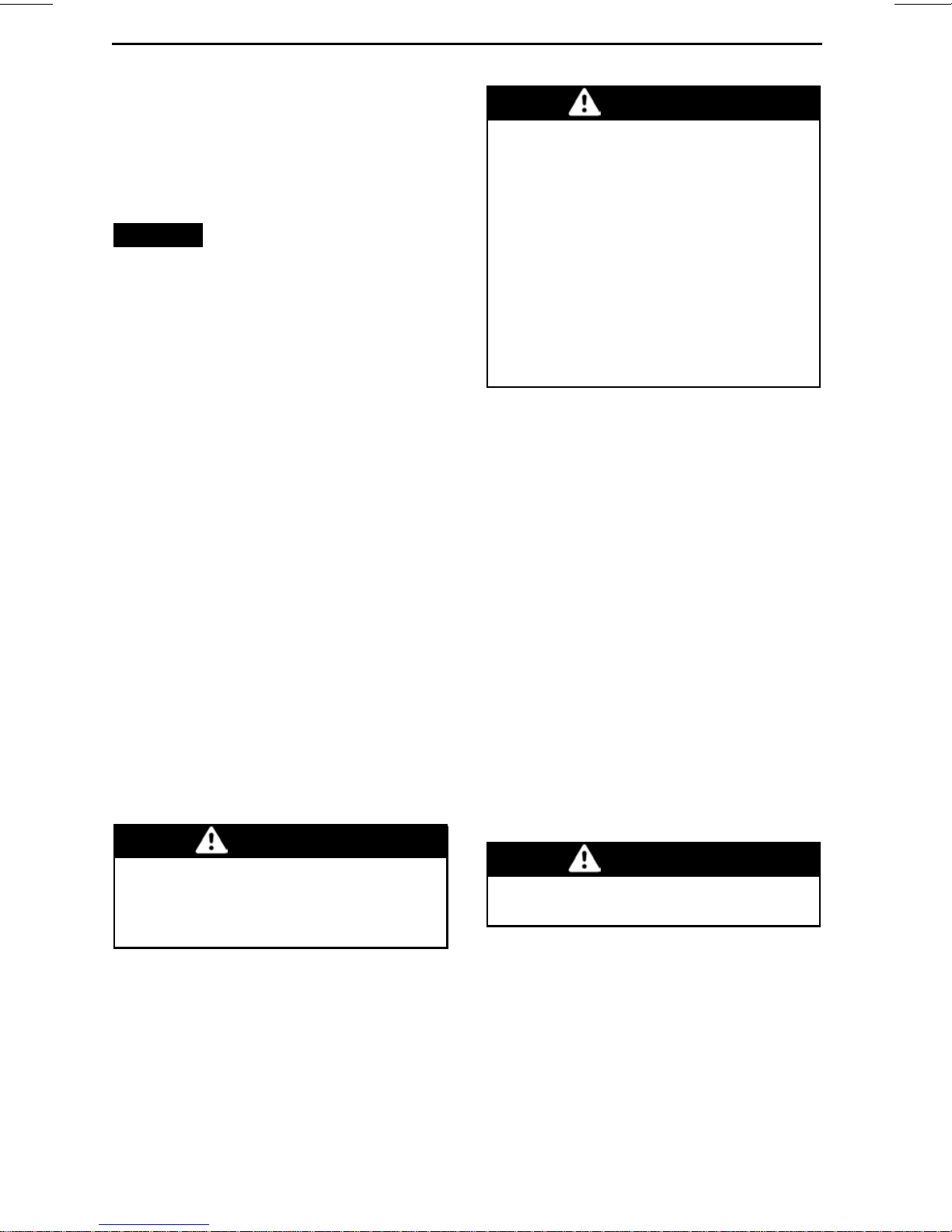
Technical Information Labels................................................... 37
PRIMARY CONTROLS ............................................................. 40
1) Steering Wheel............................................................... 40
2) Accelerator Pedal............................................................. 41
VEHICLE INFORMATION
_______________
3
Page 6

TABLE OF CONTENTS
PRIMARY CONTROLS (cont’d)
3) Brake Pedal ................................................................... 41
4) Shift Lever .................................................................... 41
SECONDARY CONTROLS......................................................... 43
1) RF D.E.S.S Key andRF D.E.S.S. Post....................................... 43
2) Engine Start/Stop Button .................................................... 44
3) Low/High Beam Headlight Switch .......................................... 44
4) 2WD/4WD Switch............................................................ 45
5) Sport/ECO Mode Switch .................................................... 45
6) Override Switch .............................................................. 45
7) DPS Switch ................................................................... 46
MULTIFUNCTION GAUGE (ANALOG/DIGITAL) ............................... 47
Multifunction Gauge Description .............................................. 47
Gauge Setup..................................................................... 51
EQUIPMENT......................................................................... 52
1) Tilt Steering ................................................................... 53
2) Cup Holders................................................................... 53
3) Passenger Handholds........................................................ 54
4) Glove Box ..................................................................... 54
5) Tool Kit......................................................................... 54
6) Footrests...................................................................... 54
7) Doors .......................................................................... 55
8) SeatBelts ..................................................................... 55
9) Driver's Seat .................................................................. 56
10) Passenger Seat ............................................................. 58
11) Fuel Reservoir Cap.......................................................... 59
12) Cargo Rack .................................................................. 59
13) Recovery Hook.............................................................. 59
14) Wheel Scraper .............................................................. 60
15) 12-Volt Power Outlet ....................................................... 60
16) Central Mirror ............................................................... 60
TUNE YOUR RIDE .................................................................. 62
Suspension Adjustment Guidelines ........................................... 62
Suspension Factory Settings................................................... 63
Suspension Adjustments....................................................... 64
DPS Function .................................................................... 67
FUEL.................................................................................. 68
Fuel Requirements.............................................................. 68
Vehicle Fueling Procedure...................................................... 68
Fueling a Gasoline Container................................................... 69
BREAK-IN PERIOD.................................................................. 70
Operation During Break-In...................................................... 70
BASIC PROCEDURES .............................................................. 71
Starting the Engine.............................................................. 71
Waking Up the ElectricalSystem .............................................. 71
Shifting the Transmission....................................................... 71
_______________
4
Page 7

TABLE OF CONTENTS
BASIC PROCEDURES (cont’d)
Choosing the Correct Range (Low orHigh) ................................... 71
Stopping the Engine and Parking the Vehicle ................................. 72
Tips for Maximizing Drive Belt D u rability ...................................... 73
SPECIAL PROCEDURES ........................................................... 74
What to do if Water is Suspected to be in the CVT ........................... 74
What to do if Battery is Drained out............................................ 74
What to do if Vehicle Rolled Over .............................................. 74
What to do if Vehicle is Submerged............................................ 74
TRANSPORTING THE VEHICLE .................................................. 75
LIFTING AND SUPPORTING THE VEHICLE ..................................... 77
Front of Vehicle.................................................................. 77
Rear of Vehicle................................................................... 77
MAINTENANCE
MAINTENANCE SCHEDULE...................................................... 80
SEVERE DUSTY CONDITIONS ................................................ 80
MAINTENANCE SCHEDULE LEGEND ....................................... 80
MAINTENANCE SCHEDULE .................................................. 81
MAINTENANCE PROCEDURES .................................................. 83
Engine Air Filter ................................................................. 83
Front Grille Kit ................................................................... 84
CVT Air Filters ................................................................... 84
Engine Oil ........................................................................ 85
Oil Filter .......................................................................... 87
Radiator .......................................................................... 88
Engine Coolant .................................................................. 88
Muffler Spark Arresters......................................................... 91
Gearbox Oil ...................................................................... 91
SparkPlugs ...................................................................... 93
CVT Cover ....................................................................... 95
DriveBelt ........................................................................ 96
Driveand Driven Pulleys........................................................ 97
Battery ........................................................................... 98
Fuses............................................................................. 98
Lights............................................................................. 99
DriveShaft Boot............................................................... 100
Wheel Bearing................................................................. 100
Wheels and Tires .............................................................. 101
Suspensions................................................................... 104
Brakes.......................................................................... 105
Seat Belts ...................................................................... 106
VEHICLE CARE .................................................................... 107
Post-Operation Care .......................................................... 107
Vehicle Cleaning and Protection ............................................. 107
_______________
5
Page 8

TABLE OF CONTENTS
STORAGE AND PRESEASON PREPARATION................................ 108
TECHNICAL INFORMATION
VEHICLE IDENTIFICATION ...................................................... 110
Vehicle Identification Number................................................ 110
Engine Identification Number................................................ 110
Radio Frequency Digitally Encoded Security System (RF D.E.S.S. key) .. 110
NOISE EMISSION CONTROL SYSTEM REGULATION ...................... 111
EC-DECLARATION OF CONFORMITY ......................................... 112
SPECIFICATIONS ................................................................. 113
TROUBLESHOOTING
TROUBLESHOOTING GUIDELINES ........................................... 122
MESSAGES IN MULTIFUNCTION GAUGE ................................... 126
WARRANTY
BRP LIMITED WARRANTY USA AND CANADA: 2017 CAN-AM
®
SSV.... 128
US EPA EMISSION-RELATED WARRANTY................................... 131
BRP INTERNATIONAL LIMITED WARRANTY: 2017 CAN-AM
®
SSV....... 134
BRP LIMITED WARRANTY FOR THE EUROPEAN ECONOMIC AREA, THE
COMMONWEALTH OF THE INDEPENDANT STATES AND TURKEY: 2017
CAN-AM
®
SSV .................................................................... 138
CUSTOMER INFORMATION
PRIVACY INFORMATION ........................................................ 144
CONTACT US...................................................................... 145
North America ................................................................. 145
Europe ......................................................................... 145
Oceania ........................................................................ 145
South America................................................................. 145
Asia............................................................................. 145
CHANGE OF ADDRESS/OWNERSHIP......................................... 146
_______________
6
Page 9

SAFETY
INFORMATION
________
SAFETY INF
ORMATION
________
7
Page 10

GENERAL PRECAUTIONS
Avoid Carbon Monoxide
Poisoning
All engine exhaust contains carbon
monoxide, a deadly gas. Breathing carbon monoxide can cause headaches,
dizziness, drowsiness, nausea, confusion and eventually death.
Carbon monoxide is a colorless, odorless, tasteless gas that may be present
even if you do not see or smell any engine exhaust. Deadly levels of carbon
monoxide can collect rapidly, and you
can quickly be overcome and unable
to save yourself. Also, deadly levels o f
carbon monoxide can linger for hours
or days in enclosed or poorly ventilated
areas. If you experience any symptoms of carbon monoxide poisoning,
leave the area immediately, get fresh
air and seek medical treatment.
To prevent serious injury or death from
carbon monoxide:
– Never run the vehicle in poorly ven-
tilated or partially enclosed areas
such as garages, carports or barns.
Even if you try to ventilate engine
exhaust with fans or open windows
and doors, carbon monoxide can
rapidly reach dangerous levels.
– Nev er run the vehicle outdoo rs
where engine exhaust can be drawn
into a building through openings
such as windows and doors.
Avoid Gasoline Fires and
Other Hazards
Gasoline is extremely flammable and
highly explosive. Fuel vapors can
spread and be ignited by a spark or
flame many feet away from the engine. To reduce the risk of fire or explosion, follow these instructions:
– Use only an approved gasoline con-
tainer to store fuel.
– Never fill the gasolin e container on
the vehicle - an electrical static discharge may ignite the fuel.
– Never carry gasoline container(s) or
any dangerous liquids on the cargo
rack unless it is designed and approved for this vehicle.
– Strictly adhere to instructions in
ELING PROCEDURE
– Never start or operate the engine if
the fuel cap is not properly installed.
Gasoline is poisonous and can cause
injury or death.
– Never siphon gasoline by mouth.
– If you swallo w g asoline, get any in
your eye(s), or inhale gasoline vapor,
see a doctor imm ediately.
If gasoline spills on yo u, w ash with
soap and water and change your
clothes.
.
FU-
Avoid Burns from Hot Parts
Certain components become hot during operation. Avoid contact with
those parts during and shortly after
operation to avoid burns.
Accessories and
Modifications
Do not make unauthorized modifications, or use attachments or accessories that are not approved by BRP.
Since these changes have not been
tested by BRP, they may increase the
risk of crash or injury, and can render
the vehicle illegal. For example, modifications such as different tires can
affect handling of the vehicle and increase risk of a crash.
See your authorized Can-Am dealer for
available accessories for your vehicle.
________
8
SAFETY IN
FORMATION
________
Page 11

SAFE OPERATION - RESPONSIBILITIES
This is a high performance off-road
vehicle. Operators must be responsibleandusecaretoavoidrollovers,
tipovers, collisions, and other accidents. Even with vehicle safety features (such as protective structure,
seat belts, doors) and protective gear
(such as a helmet), there is always a
risk of injury or death in these accidents. To reduce the risk of serious
injury or death, follow the rules in this
section.
Owner - Be Responsible
Read this Operator's Guide and watch
the
SAFETY VIDEO
Always inspect and confirm the safe
operating condition of your vehicle
prior to ride. A lwa ys follow the maintenance schedu le described in this
Operator's Guide.
Never allow anyone to operate your vehicle unless they are responsible and
can be trusted with a high performance
vehicle. Consider supervising new or
young operators and setting rules and
limits (e.g., whether they can carry a
passenger, what they may do with the
vehicle, where they may ride, etc.) for
anyone using your vehicle.
Select the appropriate key (see
D.E.S.S KEY AND RF D.E.S.S. POST
based on the operator's experience,
vehicle use and environment.
Discuss the safety information with
anyone who will be using the vehicle.
Be sure that all operators and passengers meet the qualifications below and
agree to follow the safety information.
Help users become fam iliar with the
vehicle.
We encourage you to have an Annual Safety Inspection of your vehicle. Please contact an a uth orized BRP
dealer for further details. Though not
required, it is recommended that an
authorized BRP dealer performs the
preseason preparation of your vehicle. Each visit to your autho rized BRP
.
RF
)
dealer is a great opportunity for your
dealer to verify if your vehicle is included in any safety campaign. We
also urge you to visit your authorized
BRPdealerinatimelymannerifyou
become aware of any safety related
campaigns.
Operator - Be Qualified and
Responsible
Read this Operator's Guide and watch
the
SAFETY VIDEO
Become completely familiar with the
operational controls and the general
operation of the vehicle.
Get familiar with this Off-High way Vehicle (OHV); it may exceed the performance of other OHV you may have
ridden. This is a high performance vehicle. Inexperienced riders m ay overlook risks and be surprised by the specific behavior of this vehicle in any terrain condition.
Take a training course if availab le (contact an authorized Can-Am dealer to
find out about training course availability as well as on the internet at
http://www.rohva.org/), and perfo rm
the practice exercises in
EXERCISES
ing in a suitable area free of hazards
and feel the response of each control.
Drive at low speeds. Higher speeds require greater experience, knowledge
andsuitableridingconditions.
Be at least 16 years of age.
Be tall enough to be properly seated:
back against the backrest with the
seat belt fastened, to hold the steering wheel with both hands and still be
able to reach the full stroke of brake
and accelerator pedals with the right
foot and to firmly plant left foot o n the
footrest.
Have a proper driver's license in accordance with local laws.
section. Practice driv-
.
PRACTICE
________
SAFETY INF
ORMATION
________
9
Page 12

SAFE OPERATION - RESPONSIBILITIES
Never use this vehicle with drugs or alcohol, or if tired or ill. These slow reaction time and impair judgment.
Carrying Passenger
Only carry one passenger. The passenger must be properly seated in the
cockpit.
The passenger must be tall enough
to always be properly seated: back
against the backrest with seat belt fastened, holding both handholds, and
feet firmly planted - right foot on the
footrest and the left foot on the vehicle
floor.
Never carry a passenger who has used
drugs or alcohol, or is t ired or ill. These
slow reaction time and impair judgment.
Instruct the passenger to read the vehicle’s safety labels.
Never carry a passenger if you judge
his ability or ju d gem e n t insufficient to
concentrate on the terrain conditions
and adapt accordingly. More specifically for side-by-sid e vehicles, the passenger must also pay constant attention to the terrain ahead and be able to
brace for bumps.
Riding Carefully
– Th is vehicle handles differen tly
from other vehicles. A collision or
rollover can occur quickly, during
abrupt maneuvers such as doing
sharp turns, acceleration or deceleration and driving on hills or over
obstacles, if you fail to take proper
precautions.
– Never operate at excessive speeds.
Always go at a speed that is proper
for the terrain, visibility, and operating conditions, and your experienc
– Never attempt jumps, side slid
donuts or any other stunts.
– Never attempt rapid acceleration
or deceleration when performing a
sharp turn. This may result
over.
in a roll
e.
es,
– Never attempt skidding or sliding.
If vehicle starts to skid or slide,
counter steer in the direction of
skidding or sliding. On extremely
slippery surfaces, such as ice, go
slowly and be very cautious in order
to reduce the chance o f skidding out
of control.
– Always be sure there are no obsta-
cles or people behind the vehicle
when you operate in reverse. Pay
attention to blind spots. When it
is safe to proceed in reverse, go
slowly.
– N ever exceed the stated load limits
for this vehicle. Reduce speed, allow for greater braking distance and
follow oth er instructions in
MOV-
INGLOADSANDDOINGWORK
subsection.
– Always remember that this vehicle
is heavy! Its pure weight alone may
entrap you shou ld it tip or rollover.
Occupant Restraint
System
– This vehicle is designed to carry
one driver and one passenger, both
wearing proper protective gears (refer to
– The driver and passenger must latch
the doors and wear the seat belts at
all times when riding.
RIDING GEAR
in this section).
Terrain Condition
– This vehicle is not designed to ride
on paved surfaces; if you must
shortly use the vehicle on such surfaces, avoid abrupt inputs to
ing wheel, accelerator and brake
pedals.
– Always go slowly and be extra care-
ful when operating on unfa
terrain. Always be alert to changing
terrain conditions when operating
this vehicle. Take t
how the vehicle performs in different environments.
he time to learn
steer-
miliar
10
_______
SAFETY I
NFORMATION
________
Page 13

SAFE OPERATION - RESPONSIBILITIES
– Never operate on excessively
rough, slippery or loose terrain until you have learned and practiced
the skills necessary to control this
vehicleonsuchterrain. Alwaysbe
especially cautious on these kinds
of terrain.
– Nev er operate this vehicle on hills
too steep for the vehicle or your abilities. Practice on small incline s.
– Always follow proper procedures
for climbing or going down hills as
described in
CLE
rain carefully before you start up
or down any hill. Nev er climb or descend hills with excessively slippery
or loose surfaces. Never go over
the top of any hill at high speed.
– Never attempt steep hills or side
hilling whe n pulling a trailer (if
equipped with hitch).
– Always check for obstacles before
operating in a new area. Always
follow proper procedures when operating over obstacles as described
in
tion.
– Never operate this vehicle in fast
flowing water or in water deeper
than specified in
HICLE
wet brakes may have reduced stopping ability. Test your brakes after
leaving w ater. If nece ss ary, app
them several times to let friction dry
out the brakes.
subsection. Check the ter-
RIDING YOUR VEHICLE
subsection. Remember that
RIDING YOUR VEHI-
subsec-
RIDING YOUR VE-
ly
– Alwa ys ensure to properly park the
vehicle on the flattest terrain section
available. Put shift lever in PARK,
stop engine a nd remove key before
leaving the vehicle.
– Never as sume that the vehicle will
go everywhere safely. Sudden
changes in terrain caused by holes,
depressions, banks , softer or harder
“ground” or other irregularities may
cause the vehicle to topple or become unsta ble . To avoid this, slow
down and always observe the terrain ahead. If the vehicle does begin
to topple or rollover, the best advice
is to immediately steer in the direction of the rollover! Never attempt
to pr event a rollover with your arms
or legs. You should keep your limbs
inside the cage.
________
SAFETY INF
ORMATION
________
11
Page 14

PRE-RIDE INSPECTION
Always in sp ect and confirm the safe operating condition of your vehicle prior to
ride. Always follow the maintenance schedule described in this Operator's Guide.
WARNING
Perform a pre-ride inspection before each ride to detect any potential problem that could occur during operation. The pre-ride inspection can help you
monitor component wear and deterioration before they become a problem.
Correct any problem that you discover to reduce the risk of a breakdown or
crash.
Before using this vehicle, the operator should always perform the following
pre-ride inspection check list.
Refer to
MAINTENANCE PROCEDURES
for details.
Pre-Ride Inspection Check List
What to Do Before Starting the Engine (Key OFF)
ITEMS
TO BE
INSPECTED
Check tire pressu re and condition.
28 inches
Tires
29 inches
30 inches
INSPECTION TO PERFORM
– Front: MIN 152 kPa (22 PSI),
LOADED159kPa (23PSI)
– Rear: MIN 152 kPa (22 PSI),
LOADED207kPa (30PSI)
– Front: MIN 131 kPa (19 PSI),
LOADED138kPa (20PSI)
– Rear: MIN 138 kPa (20 PSI),
LOADED186kPa (27PSI)
– Front: MIN 117 kPa (17 PSI),
LOADED124kPa (18PSI)
– Rear: MIN 165 kPa (24 PSI),
LOADED214kPa (31PSI)
✔
Wheels
Radiator
Front grille In spect front grille kit for cleanliness.
Engine oil
Coolant Check coolant level.
Brake fluid
12
_______
Check wheels for damage and for abnormal play, and check lug nuts
and beadlocks (if equipped) are tightene d.
Check radiator for cleanliness.
Check engine oil level.
Check brake fluid level.
SAFETY I
NFORMATION
________
Page 15

ITEMS
TO BE
INSPECTED
INSPECTION TO PERFORM
PRE-RIDE INSPECTION
✔
Engine air
filter
Airbox
CVT air filter Inspect and clean the CVT air filter (when riding in dusty con ditions).
Drive shaft
boots
Cargo and
load
Rear cargo
rack
Inspect engine air filter, replace if needed.
Inspect airbox and clean if necessary (when riding in dusty conditions
or sand).
Check drive shaft boots condition.
Cargo Load: If you transport a cargo, respect the maximum loading
capacity of 90 kg (200 lb) Vehicle Load: Ensure that total load on the
vehicle (including o perator, passenger, cargo, tongue weight and
added accessories) does not exceed 286 kg (630 lb).
If you are pulling a trailer or another equipment (if equipped with a
hitch):
– Check hitch and trailer ball condition.
– Respect the tongue capacity and towing capacity.
– Ensure trailer is properly secured to hitch.
Check if the cargo on rack is properly secured.
Chassis and
suspension
Check underneath vehicle for any debris on chassis or suspension
components (upper and lower arms, wheels, shock absorber, springs)
and clean them properly.
What to Do Before Starting the Engine (Key ON)
ITEMS TO BE
INSPECTED
Gauge
Lights
Check operation of indicator lamps in gauge (With the
D.E.S.S. key ON, briefly push the Start / Stop button).
Check for messages in gauge.
Check operation and cleanliness of headlights an d taillight.
Check operation o f high and low beam.
Check operation of brake lig ht.
INSPECTION TO PERFORM
✔
________
SAFETY INF
ORMATION
________
13
Page 16

PRE-RIDE INSPECTION
ITEMS TO BE
INSPECTED
Seats, doors and
seat belts
Accelerator pedal
Brake pedal
Fuel level
INSPECTION TO PERFORM
Check seat adjus tmen t and make sure locking device is
properly engaged before riding.
Check doors for any damage. Have the
doors replaced if any damage is found.
Close both doors and confirm that they latch
securely.
Check seat belts for any damage (including retractors,
buckles and locking tabs). Fasten seat belts and ensure
that they remain securely fastened and tightened against
the body
Press on the accelerator pedal a few times to ensure it
operates freely and it returns to the rest position when
released.
Press down on the brake pedal and make sure you feel
firm resistance and that it fully returns to position when
released.
Check the fuel level.
✔
What to Do After the Engine is Started
ITEMS TO BE
INSPECTED
Steering
RF D.E.S.S. post
Shift lever Check operation of shift lever (P, R, N, H and L).
2WD/4WD selector
Brakes
Check if steering operates freely by completely turning it
from side to side.
Check if D.E.S.S. post is working properly by pulling the
D.E.S.S. key from D.E.S.S. post.
Check operation of 2WD/4WD s elector.
Drive forward slowly a few feet and apply brakes. The
brake pedal must feel firm when applied. The pedal must
return to rest position when released. The brakes must
respond adequately to the driver's input.
INSPECTION TO PERFORM
✔
14
_______
SAFETY I
NFORMATION
________
Page 17
PREPARE TO RIDE
Before you Ride
Performpre-rideinspectiontoconfirm
the safe operating condition of your vehicle. Refer to
subsection.
Driver and passenger must:
– Be properly seated.
– Close both doors and fasten seat
belts.
– Wear appropriate riding gear. (Refer
to
RIDING GEAR
low.)
PRE-RIDE INSPECTION
subsection be-
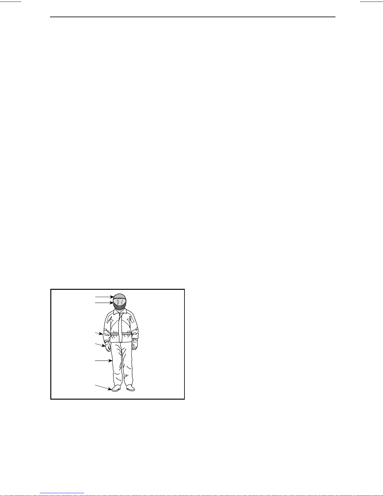
Riding Gear
It is important that the operator and
passenger always wears appropriate
protective cloth ing and apparel, including:
– An approved helmet
– Eye protection
–Boots
–Gloves
– A long sleeved shirt or jacket
– Long pants.
Depending on conditions, anti-fogging
goggles may be required.
1
2
Weather conditions should help you
decide how to dress. To maximize
comfort and avoid frostbites in winter, dress for the coldest weather expected. Thermal underwear next to
the skin also provides good insulation.
Never wear any loose clothing that
may get entangled in the vehicle or on
tree branches and shrubs.
Helmets and Eye Protection
Helmets protect the head and brain
from injury. Even with the vehicle's
cage and doors, objects can enter the
cockpit and strike the head, or the head
can strike the cage itself or objects outside the vehicle. Even the best helmet
is no guarantee against injury, but statistics indicate that helmet use significantly reduce s the risk of brain injury.
So, be safe and always wear a helmet
while riding.
Choosing a Helmet
Helmets should be manufactured to
meet the appropriate standard in your
state, province or country and should
fit properly.
Ahelmetwithfaceprotectionisabetter choice as it prote cts also against
frontal impacts. It can also protect
against debris, stones, insects, the elements, etc.
3
4
5
6
rmo2008-001-019_a
RIDING GEAR
1. Approved helmet
2. Eye and face protection
3. Long sleeves shirt or jacket
4. Gloves
5. Long pants
6. Boots (over-the-ankle footwear)
________
SAFETY INF
An open-face helmet does not offer the
same protection for the face and chin.
If you wear an open-face helmet, you
should use a snap-on face shield and/or
a pair of g oggles . Ordinary glasses or
sunglasses are not sufficient eye protection for riders. They can shatter
or fly off, and they allow wind and airborne objects to reach the eyes.
For winter riding conditions, a stocking type cap, balaclav a and face mask
should always be carried or worn.
ORMATION
________
15
Page 18

PREPARE TO RIDE
Use tinted face shields or goggles in
the daytime only; do not use them at
night or in poor illumination. Do not
use them if they impair your ability to
discern color.
Other R iding Gear
Footwear
Always w ea r closed toe footwear.
Sturdy over-the-ankle boots with
non-slip soles offer more protection
and allow you to plant your foot properly on footrest.
Avoid long shoelaces that can be tangled in the accelerator or brake pedals.
For winter riding conditions, rubber
soled boots with either a nylon or
leather uppers, with removable felt
liners are best suited.
Avoid rubber boots. Rubber boots may
get trapped behind or between pedals,
impairing the proper operation of brake
and accelerator pedals.
Gloves
Full-fingered gloves protect hands
from the wind, sun, heat, cold and flying objects. Gloves that fit snu gly will
improvegriponthesteeringwheeland
help reduce hand fatigue. Sturdy, reinforced motorcycle or ATV gloves help
protect hands better in the event of an
accident or a rollover. If gloves are too
bulky, it may be difficult to operate the
controls.
For winter riding conditions, hands
should be protected by a pair of snowmobile glo ve s which have sufficient
insulation and allow use of thumbs and
fingers for operation of controls.
crash, good quality protective gear
made of sturdy material may prevent
or reduce injury.
In cool-weather riding, protect yourself against hypothermia. Hypothermia, a condition of low body temperature, can cause loss of concentration,
slowed reactions and loss of smooth,
precise muscle movement. In cool
conditions, proper protective gear like
a windproof jacket and insulated layers
of clothing are essential. Even while
riding at moderate temperatures, you
can feel very cold due to the wind.
Protective gear that is appropriate for
cold-weather riding may be too hot
when stopped. Dress in layers so that
clothing can be removed as desired .
Topping the protective gear with a
windproof outer layer can prevent cold
air from reaching the skin.
Rain Gear
Ifyoumustrideinwetweather,arain
suit or a waterproof ridin g suit is recommended. On long rides, it is a good
idea to carry rain gear. A dry rider will
be much more comfortable and alert.
Hearing Protection
Long-term exposure to wind and engine noise when riding can cause permanent hearing loss. Properly worn
hearing protective devices such as
earplugs can help prevent hearing loss.
Check local laws before using any hearing protective devices.
Jackets, Pants and Riding Suits
Wear a jacket or a long sleeved shirt
and long pants, or a full riding suit.
Quality ATV-type protective gear will
provide comfort, and it can help you
avoid being distracted by adverse environmental elements. In case of a
16
_______
SAFETY I
NFORMATION
________
Page 19

AVOID ACCIDENTS
Avoid Rollovers and
Tipovers
Side-by-side vehicles handle differently from other vehicles. Side-by-side
vehicles are designed to handle
off-road terrain (for example, their
wheel base and track width, ground
clearance, suspension, drive train,
tires, etc.), and, as a result, can overturn in situations where vehicles designed for use primarily on paved or
smooth terrain may not.
A rollover or other accident can occur quickly during abrupt maneuvers
such as sharp turns or hard acceleration or deceleration when turning, or
when driving on hills or ove r obstacles. Abrupt maneuvers or aggressive
driving can cause rollovers or loss of
control even in flat open areas. If the
vehicle rolls over, any part of your body
(such as arms, legs, or head) outside of
the cockpit can be crushed and trapped
by the cage or other parts of the vehicle. You can also be injured by impact
with the ground, cockpit or other objects.
To re d uce the ris k of rollovers:
– Use care when turning.
• D o not turn th e steering whee l
too far or too fast for your speed
and environment. Adjust s teering inputs according to your
speed and environment.
• Slow down before entering a
turn. Avoid hard braking during
a turn.
• Avoid sudden or hard acceleration when turning, even from a
stop or low speed.
– Never attempt donuts, skids, slides,
fishtails, jumps, or other stunts. If
vehicle starts to skid or slide, steer
in the dire ction of the skid or slide.
Never slam the brakes and lock the
wheels.
– Avoid paved surfaces. This vehi-
cle is not designed to operate on
paved surfaces and is more likely to
roll over. If you must drive on pavement, turn gradually, go slowly, and
avoid abrupt acceleration and braking.
This vehicle can roll over sideways
or tip over forward or backwards on
slopes or uneven terrain.
– Avoid side hilling (driving along the
slope rather than up or down a hill).
When possible, drive straight up and
down inclines rather than across
them. If you must side hill, use extreme caution and avoid slippery
surfaces, objects, or depressions. If
you feel the vehicle start to rollover
or slide sideways, ste e r downhill if
possible.
– Avoid s te ep hills and follow proce-
dures in this guide for climbing and
descending h ills.
– Sudden changes in terrain such as
holes, depressions, banks, softer or
harder ground or other irregularities
may cause the vehicle to tip or become unstable. Observe the terrain
ahead and slow down in areas of uneven terrain.
This vehicle will handle differently
when carrying or pulling a load.
– Reduce speed and follow instruc-
tions in this manual for carrying
cargo or pulling a trailer.
– Avoid hills and rough terrain.
– Allow more distance to stop.
________
SAFETY INF
Be Prepared in Case of Rollover
– Close both doors and fasten seat
belt to help you avoid sticking out
arms or legs.
ORMATION
________
17
Page 20

AVOID ACCIDENTS
– N ever grab the cage while riding.
Hands can be crushed between the
cage and the ground in a rollover.
Keep hands on the steering wheel
or handholds.
– Nev er try to stop a rollover u sin g
your arms or legs. If you think that
the vehicle may tip or roll, the driver
should keep both hands on the
steering wheel and the left foot
firmly planted on the footrest. The
passenger should keep both hands
on the handholds and both feet
firmly planted on the floor.
Avoid Collisions
This vehicle can reach high speeds. At
higher speeds, there is an increased
risk of losing control, particula rly in
challenging off-road conditions, and
the risk of injury in a co llisio n is greater.
Never operate at excessive speeds.
Always go at a speed that is proper for
the terrain, visibility, and operating conditions, and your experience. Consider
reserving use of th e performance key
for situations in which full speed and
acceleration capability are appropriate.
Never operate this vehicle on any public street, road or highway, even dirt
or gravel ones. Riding your vehicle on
roads or highways could result in a collision with another vehicle. This vehicle
is not designed for operation on roads.
For example, it does not meet motor
vehicle safety standards that apply to
automobiles. In many jurisdictions it
is not legal to operate this vehicle on
public roads.
This vehicle does not have the same
kind of protection for collisio
car; for example, there are no air bags,
the cockpit is not fully enclosed, and
it is no t designed for collisi
other vehicles. Therefore, it is particularly important to fasten seat belts an d
closedoorsandwearana
met.
ns as a
ons with
pproved hel-
18
_______
SAFETY I
NFORMATION
________
Page 21

RIDING YOUR VEHICLE
Practice Exercises
Before you go out for a ride, it is very
important to familiarize yourself with
thehandlingofyourvehiclebypracticing in a controlled environment. If
possible, it is also a very good idea to
take a more formal training course to
sharpen your skills and increase your
knowledge of the vehicle.
Find a suitable a rea to practice and
perform the following exercises. It
should be at least 45 m (150 ft) by 45 m
(150 ft) free of obstacles like trees and
rocks. Once you’ve selected a suitable
permitted location, proceed with the
following practice ex ercises.
Turning Exercises
Turning is one of the most frequent
causes of accidents. It is easier for the
vehicle to lose traction or rollover if you
turn too sharply, or go too fast. Slow
down when you approach a turn.
– First learn how to perform slight
right turns at very low speeds. Release the throttle before turning and
slowly reapply the throttle when
turning.
– Repeat turning exercise but this
time maintain the throttle at the
level while turning.
– Finally, repeat turning exercise
while accelerating slowly.
– Practice exercises turning on the
other sid e.
Note how your vehicle reacts in th ese
different exercises. We recommend
releasing the throttle before entering a
turn to he lp initiate directional change.
You will feel the lateral force increasing
with the speed and with your steering input. The lateral force should be
maintained as low as possible to make
sure it does not cause the vehicle to
roll over.
UTurnExercises
Practice doing U turns.
– Acce lerate slowly and while remain-
ing at low speed, then gradually turn
the steering wheel to the right until
you have completed the U turn.
– Repeat U turn exercise with differ-
ent steering inputs and always at a
very low speed.
– Repeat U turn exercise on the other
side.
As mentioned before in this guide, do
not ride on paved surfaces as the vehicle behavior will not be the same,
increasing the r isk of rollover.
Braking Exercises
Practice braking to get familiar with the
brake response.
–Doitatlowspeedfirst,thenin-
crease the speed.
– Practice braking in straight line at dif-
ferent speeds and different braking
force.
– Practice emergency braking; opti-
mal braking is obtained in straight
line, with high force applied, with-
out locking the wheels.
Remember, braking distance depends
on vehicle speed, load and the type of
surface. Also, the tires and brakes conditions play a major role.
Reverse Exercises
The next step involves using the reverse.
– Ins tall 1 cone marker on both sides
of the vehicle beside each rear
wheel. Move the vehicle forward
until you can see the cone markers,
then stop the vehicle. Acknowl-
edge the distance required to see
obstacles behind you.
– Learn how the vehicle handles itself
in reverse and reacts with steering
inputs.
________
SAFETY INF
ORMATION
________
19
Page 22

RIDING YOUR VEHICLE
– A lways perform this reverse exer-
cise at slow speeds.
– Become familiar with the usage of
the override function. Do not steer
while using the override as it increases the risks of rollover.
Emergency Engine Stopping
Exercise
Learn how to stop your engine quickly
in an emergency situation.
– While running at low speed, simply
remove the RF D.E.S.S. key from
the D.E.S.S. post.
This is to familiarize you with the vehicle’s reaction when the engine is
turned off while driving and to develop
this reflex.
Off-Road Operation
The very nature of off-road operation
is dangerous. Any terrain, which has
not been specially prepared to carry
vehicles, presents an inherent danger
where terrain substance, shape and
steepness are unpredictable. The terrain itself presents a continual element
of danger, which must be knowingly
accepted by anyone venturing over it.
An operator who takes a vehicle
off-road should always exercise the utmost care in selecting the safest path
and keeping close watch on the terrain ahead of him. The vehicle should
never be operated by anyone who is
not completely familiar with the driving
instructions applicable to the vehicle,
nor should it be operated on steep or
treacherous terrain.
General Riding Techniques
General Driving Tips
Care, caution, experience and driving
skill are the best precautions aga
the hazards of vehicle operation.
inst
Whenever there is the slightest doubt
that the vehicle can safely negotiate an
obstacle or a particular piece of terrain,
always choose an alternate route.
In off-road operation, power and traction, not speed, are important. Never
drive faster than visibility and your own
ability to select a safe route permit.
Always go slowly and be extra careful
when operating on unfamiliar terrain.
Always be alert to changing terrain conditions when operating this vehicle.
Be especially cautious on excessively
rough, slippery, icy or loose terrain.
Constantly watch the terrain ahead
for sudden changes in slopes or obstacles, such as rocks or stumps, that
may cause loss of stability, resulting in
tipoverorrollover.
Never operate the vehicle if the controls do not function normally. See an
authorized Can-Am dealer.
To m aintain proper control it is strongly
advised that you keep your hands on
the steering wheel and within easy
reach of all controls. The same holds
true for your feet. To minimize the possibility of a ny leg or foot injury, keep
your left foot on the footrest and right
foot on the floor at all tim es. Staying
completely within the cockpit will also
help keep you from striking objects
outside the vehicle.
Watch for and avoid branches and
other objects that could enter the cockpit and strike you or your passenger.
Operating in Reverse
When operating in reverse, check that
the path behind the vehicle is free of
people or obstacles. Pay attention to
blind spots. When it is safe to procee
in reverse, go slowly and avoid sharp
turns.
WARNING
d
20
_______
SAFETY I
Steering inputs in reverse operation increase the risk of rollover.
NFORMATION
________
Page 23

RIDING YOUR VEHICLE
NOTE: In reverse operation, the engine RPM is limited thus limiting the
vehicle reverse speed.
WARNING
When driving downhill in reverse,
gravity can increase the vehicle
speed above the set limited reverse speed.
Crossing Roads
If you have to cross a road, ensure to
have complete visibility on both sides
forincomingtrafficanddecideonexit
point on other side of road. Drive in
a straight line toward that point. D o
not make sharp direction changes or
abrupt accelerations as it may result
in a rollover situation. Do not t ravel on
sidewalks or bicycle trails as they are
designated specifically for those uses.
Riding on Paved Surfaces
Avoid paved surfaces. This vehicle is
not designed to operate on paved surfaces and is more likely to r oll over.
If you must drive on pavement, turn
gradually, go slowly, and avoid abrup t
acceleration and braking.
Shallow Water Crossing
Water can be a unique hazard. If it is
too deep the vehicle may “float” and
topple. Check the water depth and current before you attempt to cross any
water. Water depth should not exceed
30 cm (12 in) for ve hicle to safely cross
the obstacle. Beware of slippery surfaces such as rocks, grass, logs, etc.,
both in the water and on its banks. A
loss of traction may occur. Do not attempt to enter the water at high speed.
Water will affect the braking ability of
your vehicle. Make sure you dry the
brakes by applying them several times
after the vehicle leaves t he water.
Mud or marsh lands may be encountered near water. Be prepared for sudden “holes” or changes in depth. Sim-
ilarly so, be watchful of hazards such
as rocks, logs, etc., partially covered by
vegetation.
Riding on Snow or Ice
When performing pre-ride inspection,
pay special attention to locations on
the vehicle where snow and/or ice accumulations may obstruct visibility of
the tail lamp, clog ventilation openings,
block the radiator and fan, and interfere
with the movement of controls. Before starting with your vehicle, check
the steering, accelerator and brake
pedals for interference free operation.
Whenever this vehicle is ridden on a
snow covered drive path, the tire grip
is generally reduced causing the vehicle to react differently to control inputs from the operator. On low grip
surfaces, the steering responses are
not as crisp and precise, stopping distances are lengthened and acceleration is also affected. Slow down and
do not "gun" the accelerator. This will
only result in spinning of the tires and
possiblyinanoversteeringslideofthe
vehicle. Avoid hard braking. This will
possibly result in a straight line slide of
the vehicle. Again, th e best advice is to
safely reduce speed in anticipation of
a maneuver to give yourself time and
distance in order to keep control of the
vehicle.
As you drive your vehicle over a loose
snow covered surface, snow dust will
be picked up in the wake turbulence
of the moving vehicle and transported
to contact and accumulate or melt o
some exposed components including
rotating parts like brake discs. Water,
snow or ice may affect the respo
time of the b ra ke system of your vehicle. Even when not required to reduce
vehicle speed apply brakes f
to prevent ice or snow accumulation
and to dry brak e pads and discs. While
doing so in low risk driv
you will test for grip level and keep
yourself alerted to how the vehicle reacts to your control i
nputs. Always
requently
ing situations
n
nse
________
SAFETY INF
ORMATION
________
21
Page 24

RIDING YOUR VEHICLE
keep brake and accelerator pedals and
floor boards free of snow and ice. Frequently wipe snow off seat, steering
wheel, headlights and tail lamps.
The depth of the snow cover may hide
rocks, tree stumps or other objects and
if it is wet may totally impede the drivability as th e vehicle becomes bogged
down or completely looses traction in
slushy snow. Look far ah ead and always be watchful of any visible clues
that might indicate the presence of
such obstacles. In doubt steer clear.
Avoid driving on any frozen waterways
before checking that the ice will safely
support the vehicle, its riders and its
load of cargo.
At the end of each ride it is a good practice to clean the vehicle and all moving
components (brakes, steering components, drivelines, controls, radiator
fan e tc .) from any snow or ice accumulations. Wet snow will turn to ice
during the shut down period and become more difficult to rem ove at the
next pre-ride inspection.
Riding on Sand
Sand and riding on sand dunes is another unique experience but there are
some basic precautions that should
be observed. Wet, deep or fine sand
may create a loss of trac tion and cause
the vehicle to slide, drop off or become
“bogged” down. If this occurs look for
a firmer base. Again, the best advice
is to slow down and be watchful of the
conditions.
When riding in sand dunes it is advisabletoequipthevehiclewithanantenna type safety flag. This will h
make your location more visible to others over the next sand dune. Proceed
carefully should you see anoth
flag ahead.
er safety
elp
Riding on Gravel, Loose Stones or
Other Slippery Surfaces
Riding on loose stones or gravel is very
similar to riding on ice. They will affect
the steering of vehicle, poss ibly causing it to slide and tip over espec ially at
high speeds. In addition, braking distance may be affected. Remember
that “gunning” the throttle or sliding
may cause loose stones to be ejec ted
rearwards into the path of another
rider's way. Never do it deliberately.
If y ou do get into a slide or sk id, it may
help to turn the steering wheel into the
directionoftheskiduntilyouregain
control. Never jam the brakes and lock
the wheels.
Crossing Obstacles
Use the low range (L) for crossing obstacles.
Obstacles on the “trail” should be traversed with caution. This includes
rocks, fallen trees, and depressions.
You should avoid them whenever possible. Remember that some obstacles
are too large or dangerous to cross
and should be avoided. As a guideline,
never attempt to cross an obstacle
higher than the ground clearance of
the vehicle. Small rocks or small fallen
trees may be safely crossed - approach
obstacle at low speed and as much as
possible at a right angle. Adjust speed
without losing momentum and do not
accelerate abruptly. Passenger must
grasp both handholds firmly and brace
feet on the floor. Hold steering firm
without closing your fists around it and
proceed. Be aware that the obstacle
may be slippery or may move while
crossing.
Hill Driving Conditions
When driving on hills or slopes, two
things are highly important:
pared for slippery surfaces or terrain
variations and obstacles and brace
yourself properly inside v
climb or descend a hill th at is too slip-
ehicle. If you
be pre-
ly
22
_______
SAFETY I
NFORMATION
________
Page 25

RIDING YOUR VEHICLE
pery or has too loose a surface, you
can lose control. If you go over the
top of a hill at high speed, you may not
have time to prep are for the terrain
on the other side. Avoid parking on
a slope. Always p ut the shift lever in
PARK when stopped or parked, especially on an incline, to avoid rolling. If
you must park on a steep incline, block
the wheels using rocks or bricks.
Uphill Driving
Use the low range (L) for uphill driving.
Due to its configuration, this vehicle
has very good traction even while
climbing, so much so that tip o ver is
possible before traction is lost. For
example, it is common to encounter
terrain situations where the top of the
hill has eroded to a point that the hill
peak rises very sharply. This vehicle is
not designed to negotiate such a condition. Take an alternate route.
It is also wise to know the terrain condition on the other side of the hill or
bank. All too often there exists a sharp
drop-off that is impossible to negotiate
or descend.
If you feel that the slope is getting too
steep to climb, apply brakes to immobilize vehicle. Put shift lever in reverse
(R), and back down the hill, barely releasing brakes to remain at low speed.
Do not attempt to turn around. Never
coast down hill while veh icle is in neutral. Do not perform hard braking as it
increases the risk of tipover.
Downhill Driving
This vehicle can climb steeper slopes
than it can descend safely. Therefore
it is essential to assure that a safe route
exists to descend a slope before you
climb it.
Decelerating while negotiating a slippery downhill slope could “tobo
the vehicle, causing it to slide. Maintain steady speed and/or accelerate
slightly to regain control. N
brakes and lock the wheels.
ggan”
ever slam
Side Hilling
Whenever possible, sidehilling (driving across a slope rather than up or
down it) should be avoided. If necessary, do so with extreme caution. Side
hilling on steep inclines could result in
rollover. In addition, slippery or unfirm
surfaces could result in uncontrollable
side sliding. Avoid all objects or depressions that will in tensify the raising
of one side of the vehicle higher than
the other, thus causing rollover. If you
feel the vehicle start to rollover or slide
sideways, steer downhill if possible.
WARNING
Be careful when loading and transporting liquid reservoirs. They can
affect vehicle stability when side
hilling by pulling downhill and increasing the risk of a roll over.
Drop-Offs
This vehicle is not designed to negotiate drop-offs. It will “bottom-out” and
usually stop if either the front or rear
wheels are driven over a drop-off. If
the drop is sharp or deep, the vehicle
will nose dive and tip over.
Avoid negotiating drop-offs. Reverse
and select an alternate route.
Recreational, Group and Distance
Riding
Respect the rights and limitations of
others. Stay away from areas designated for other types of off road
use. This includes snowmobile trails,
equestrian trails, cross country ski
trails, mountain bike trails, etc. Never
,
assume there are no other users on
the trail. Always stay to the right of the
trail and do not zig zag to one side of
the trail then the other. Be prepared
to stop or pull off to the side if another
trail user appears in front of you.
Join a local side-by-side vehicle club. It
will provid e you with a map and advice
or inform you where you can ride. If a
________
SAFETY INF
ORMATION
________
23
Page 26

RIDING YOUR VEHICLE
club does not exist in your area, help
to start one. Group riding and club activities provide a pleasurable, social
experience. Never use with drugs or
alcohol, or tired or ill.
Always keep a safe distance from
other riders. Your judgment of speed,
terrain conditions, weather, mechanical condition of your vehicle and the
“trust in judgment” you have in others
around you will help you make a better
choice of appropriate safe distance.
This vehicle, like any other motorized
vehicle, cannot stop “on a dime”.
Before you ride, tell someone where
you are planning to travel and your expected time of return.
Depending on the length of your ride,
carry additional tools or emergency
equipment. Find out where you can
get additional gasoline. Be prepared
for the possible conditions you may
encounter. An emergency first aid kit
should always be a consideration.
hicle. If you encounter animals on the
trail, stop and observe quietly and with
caution. It will be one of the better
memories of your life.
Observe the rule... “what you take in,
carry out”. Do not litter. Do not start
campfires unless you have permission
to do so, and then only away from dry
areas. The hazards you may crea te on
the trail may cause injury to others or
yourself, even at a later date.
Respect farm lands. Always obtain the
permission of the landowner before
riding on private land. Respect crops,
farm animals and property lines.
Finally, do not pollute streams, lakes or
riversanddonotmodifytheengineor
exhaust system, or remove any of its
components as it will alter the vehicle
emissions.
Environment
One of the benefits of this vehicle is
that it can take you off the beaten path
away from most communities. However, you should always respect nature and the rights of others to enjoy
it. Do not ride in environmentally sensitive areas. Do not drive over forest
crops or shrubs, nor cut down trees
or take down fencing, nor spin your
wheels and destroy the terrain. “Tread
Lightly”.
This vehicle can cause OHV wildfires
if debris builds up near the exhaust
or other engine hot spots and ignites
then falls off into dry grass. Avoid riding in wet areas, through muskeg or
tall grass, where debris can build up.
Should you ride in those areas, inspect
and remove all debris from you
gine and hot spots. Refer to
NANCE
section for details .
ren-
MAINTE-
Chasing w ild life is in many areas illegal. Wildlife can die of ex haustion
after being chased by a moto
24
_______
rized ve-
SAFETY I
NFORMATION
________
Page 27

MOVING LOADS AND DOING WORK
WorkingwithyourVehicle
Your vehicle can help you perform a number of different LIGHT tasks ranging
from snow removal to carrying cargo. A variety of ac cessories are available from
your authorized Can-Am dealer. To pre vent possible injury, follow the instructions
and warnings tha t accompany the accessory. Always respect the load lim its of
the vehicle. Overloading the vehicle can overstress the components and cause
failure. Avoid overex erting your self if you lift or pull heavy loads or manually push
the vehicle.
Carrying Loads
Any load carried on th e vehicle will affe ct the handling, stability and braking
distance of the vehicle. Do not exceed the load limits of the vehicle, including
the weight of operator, passenger, cargo, accessories and trailer tongue weight.
Alwaysbeawarethatthe“load”mayslideorfalloffandcreateanaccident.
LOAD LIMIT OF THE VEHICLE
286kg (630lb)
Following are examples of suitable total vehicle load distribution:
EXAMPLES OF SUITABLE VEHICLE TOTAL LOADS (LOW RANGE)
OPERATOR
AND
PASSENGER
171 kg (377 lb) 31 kg (68 lb) 25 kg (55 lb) 59 kg (130 lb) 286 kg (630 lb)
NOTE: When the vehicle's transmission is in high range, the combined weight on
cargo rack and tongue weight must not exceed 90 kg (200 lb).
To reduce the risk to lose control or the load carried, follow these recommendations.
Vehicle Settings When Carrying
Load
When the total load exceeds 195 kg
(430 lb), including weight of operator,
passenger, cargo, accessories and, if
applicable, trailer tongue weight, inflate the tires to maximum pressure.
CARGO LOAD ACCESSORIES
Includes occupants, cargo, added accessories,
and tongue weight (if applicable)
TONGUE
WEIGHT
MAXIMUM PRESSURE
SIZE FRONT REAR
28 inches
29 inches
159 kPa
(23 PSI)
138 kPa
(20 PSI)
TOTAL
VEHICLE
LOAD
207 kPa
(30 PSI)
186 kPa
(27 PSI)
________
SAFETY INF
30 inches
NOTE: When carrying a passenger or
heavy loads readjust suspension accordingly.
ORMATION
124 kPa
(18 PSI)
________
214 kPa
(31 PSI)
25
Page 28
MOVING LOADS AND DOING WORK
NOTE: When carrying heavy loads in
cargo rack or pulling a load e d trailer
operate with the shift lever in L (low
range).
Loading the Cargo Rack
NOTICE
ing, do not exceed the weight limit
of 90 kg (200 lb).
Load cargo as low as possible – a
higher load can raise the vehicle’s
center of gravity, which can reduce
stability. Position cargo on the rack as
evenly as possible.
Securetheloadonthecargorack. Do
not secure cargo to the cage or other
part of the vehicle. If it is not properly secured, a load may slide or fall
off, possibly striking occupants or bystanders; or it may shift during riding,
affecting the handling of the vehicle.
Objects that are high may affect visibility for the driver and may act as projectiles in case of an accident. Loads that
protrude sideways can get snagged or
caught in bu sh, branches or other obstacles. Avoid covering and obstructing the brake lights with the cargo.
Ensure no cargo protrudes outside the
cargo rack and that cargo will not interfere with your visibility or control of the
vehicle.
Do not overload cargo rack.
When loading or unload-
WARNING
Never carry gasoline container(s)
or any dangerous liquids on the
cargorackunlessitisdesigned
and approved for this vehicle.
WARNING
Never overload, tow or carry cargo
improperly. Safely reduce speed
according to terrain conditions
when carrying cargo or pulling a
trailer, and avoid hills and rough
terrain. Allow greater distance for
braking. Always secure cargo as
low as possible to reduce the effect of a higher center of gravity.
Failure to follow the recommendations here could cause changes in
vehicle handling which could lead
to an accident.
Hauling a Load
(if Equipped with Hitch)
Never pull a load by attaching it to the
cage; this can cause the vehicle to tip
over. Use only the trailer hitch (if installed) to pull a load.
In an emergency situation, use the recovery hook to recover a stuck vehicle.
When pulling loads with a chain or cable, ensure that there is no slack before
starting and maintain tension while
pulling.
When pulling loads with a chain or cable, be sure to brake progressively.
The inertia of the load could lead to an
impact.
When hauling a lo ad, respect the maximum hauling capacity. See
ATRAILER
subsection.
PULLING
WARNING
Slack can cause the chain or cable
to break and snap back.
When pulling another vehicle, be sure
that someone is controlling the pull
vehicle. They must brake and steer to
prevent the vehicle from going out of
control.
ed
26
_______
SAFETY I
Reduce your speed when hauling a
load and turn gradually. Avoid
rough terrain. Never attempt steep
hills. Allow more distance for brak-
NFORMATION
________
hills an d
Page 29

MOVING LOADS AND DOING WORK
ing, especially on inclined su rface s
and whe n a passeng e r is on board. Be
careful not to skid or slide.
Pulling a Trailer
(if Equipped with Hitch)
NOTICE
hitch must be properly installed on
the vehicle for hauling trailers.
Riding this vehicle with a trailer substantially increases the risk of toppling,
especially on inclined slopes. If a trailer
is used behind the vehicle make sure
that its hitch is compatible with the
one on the vehicle. Make sure the
trailer is horizonta l with the vehicle. (In
some instances a special extension
may have to be installed on the vehicle
hitch). Use security cha ins or cables to
secure the trailer with the vehicle.
Reduce your speed when pulling a
trailer and turn gradually. Avoid hills
and rough terrain. Never attempt
steep hills. Allow more distance for
braking, especially on inclined surfaces
and whe n a passeng e r is on board. Be
careful not to skid or slide.
A BRP approved rear
Use caution when disconnecting a
loaded trailer; it or its load may topple
on you or others.
When hauling a trailer, respect the maximum hauling capacity indicated on
thelabelonthehitch.
Improperly loading a trailer m a y cause
loss of control. Respect the recommended maximum hauling capacity
and maximum tongue load (Refer to
MAXIMUM HAULING CAPACITY
ble). Make sure there is at least some
weight on the tongue.
Always make sure load is evenly distributed and safely secured on the
trailer; an evenly balanced trailer is
easier to control.
Always put the shift lever to L (low
range) for hauling a trailer – in addit
to providing more torque, operating
in low range helps account for the increasedloadonthereartires.
When stopped or parked, block the vehicle and trailer wheels from po
movement.
ta-
ion
ssible
________
SAFETY INF
ORMATION
________
27
Page 30
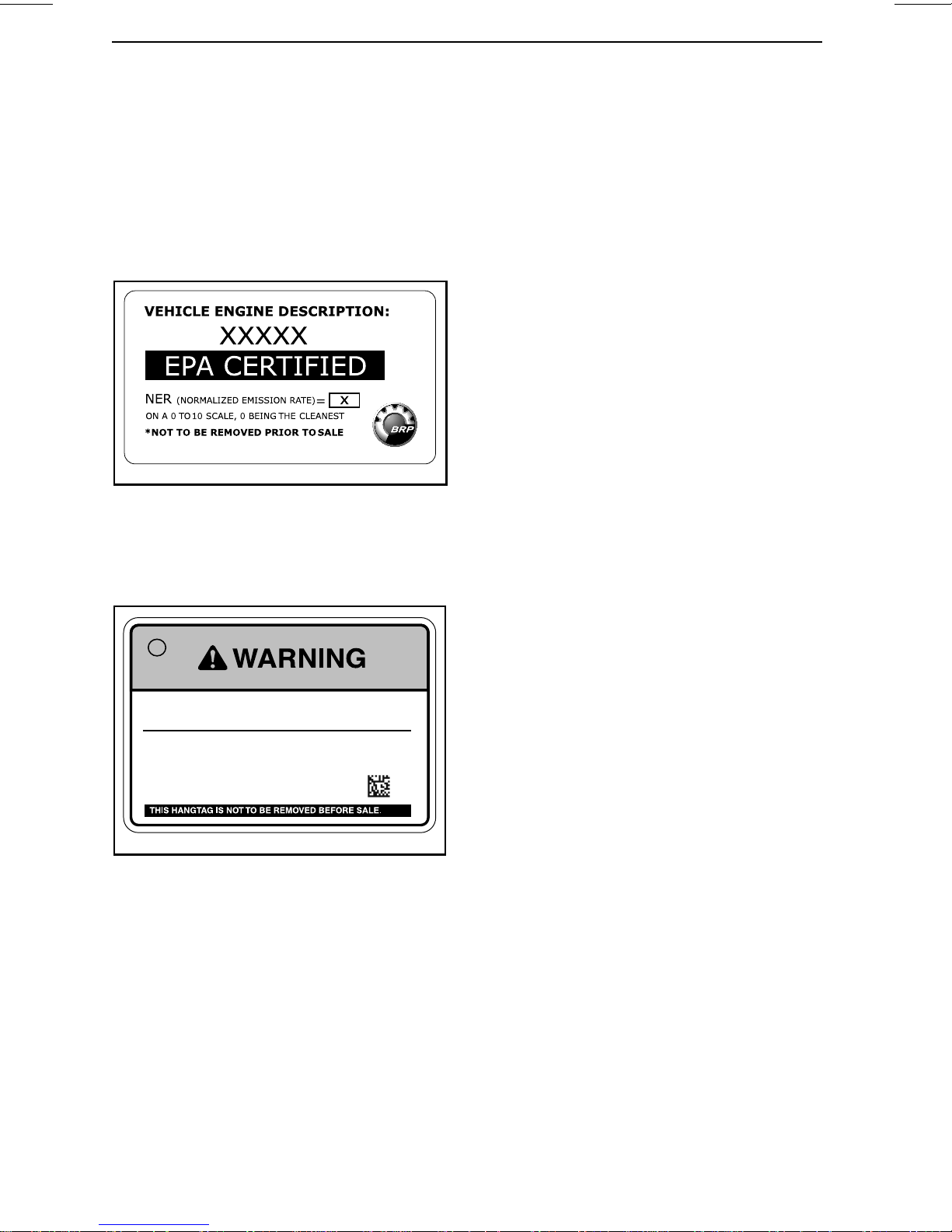
IMPORTANT ON-PRODUCT LABELS
Hang Tag
This vehicle comes with a hang tag and
labels containing important safety information.
Any person who rides this vehicle
should read and understand this information before riding.
704901107
vmo2006-005-009_en
TYPICAL: APPLICABLE FOR ALL MODELS
IN CANADA AND UNITED STATES,
APPLICABLE FOR MODELS EVERYWHERE
EXCEPT CANADA AND UNITED STATES
WHEN EQUIVALENT TO A MODEL
CERTIFIED TO US. EPA STAN DA R DS
NOTE: In the event of any discrepancy between this guide and the vehicle, the s afety labels on t he vehicle
have precedence over the labels in this
guide.
GET FAMILIAR WITH THIS OFF-HIGHWA Y VEHICULE
(OHV); IT MAY EXCEED THE PERFORMANCE OF
OTHER OHV YOU MAY HA VE RIDDEN.
THIS IS A HIGH PERFORMANCE OHV.
INEXPERIENCED RIDERS MAY OVERLOOK
RISKS AND BE SURPRISED BY THE SPECIFIC
BEHAVIOR OF THIS OHV IN ANY
TERRAIN CONDITION.
EN-704906437-DEC
734609407
Safety Labels
Read and understand all the safety labels on your vehicle.
These labels are affixed to the vehic le
for the safety of the operator, passen
ger or bystanders.
The following labels are on your v
cle, and they should be considered permanent parts of the vehicle. If missing
or damaged, they can be replace
of charge. See an authorized Can-Am
dealer.
ehi-
dfree
-
28
_______
SAFETY I
NFORMATION
________
Page 31

IMPORTANT ON-PRODUCT LABELS
219001761-003_b
________
SAFETY INF
ORMATION
________
29
Page 32

IMPORTANT ON-PRODUCT LABELS
Improper Use of Off-Highway Vehicles Can
Cause Severe Injury or Death
Be Sure Riders Pay Attention and Plan Ahead
If you think or feel the vehicle may tip or roll,
reduce your risk of injury:
• Keep a firm grip on the steering wheel or handholds and brace yourself.
• Do not put any part of your body outside of the vehicle for any reason.
Be Prepared
• Fasten seat belts and close doors.
• Wear an approved helmet and protective gear.
• Each rider must be able to sit with back against seat, foot
flat on the floor or on footrest, and hands on steering
wheel or handholds. Stay completely inside the vehicle.
EN-704906372-DEC
LABEL 1
rollovers:
• Avoid abrupt maneuvers,
sideways sliding, skidding or
fishtailing, and never do donuts.
• Slow down before entering a turn.
• Avoid hard acceleration when turning,
even from a stop.
• Plan for hills, rough terrain, ruts, and other
changes in traction and terrain. Avoid
paved surfaces.
• Avoid side hilling (riding across slopes).
Rollovers have caused severe
injuries and death, even on flat,
open areas.
Drive Responsibly
Avoid loss of control and
704906372
30
_______
SAFETY I
NFORMATION
________
Page 33

Improper Use of Off-Highway Vehicles
Can Cause Severe Injury or Death
Be prepared in case of rollover
• Hold the cage while riding.
• Try to stop a rollover using
your arm or leg.
• Fasten seat belts and close doors.
Require Proper Use of Your Vehicle
Do your part to prevent injuries:
• Do not allow careless or reckless driving.
•Make sure operators are 16 or older
with a valid driver's license.
• Do not let people drive or ride after using
alcohol or drugs.
• Do not allow operation on public roads
(unless designated for off-highway
vehicle access) – collisions with cars
and trucks can occur.
• Do not exceed seating capacity:
2 occupants.
IMPORTANT ON-PRODUCT LABELS
EN-704906148-DEC
LABEL 2
Read the Operator's
Guide and Safety Labels
and Watch the Safety
Video.
Follow All
Instructions and
Warnings.
704906148B
________
SAFETY INF
ORMATION
________
31
Page 34

IMPORTANT ON-PRODUCT LABELS
PASSENGER
Improper Use of Off-Highway Vehicles
Can Cause Severe Injury or Death
Be prepared in case of rollover
• Hold the cage while riding.
• Try to stop a rollover using your arm or leg.
• Fasten seat belts and close doors.
Be Prepared
• Fasten seat belts and close doors.
• Wear an approved helmet and protective gear.
• Each rider must be able to sit with back agains
seat,foot flat on the floor or on footrest, and
hands on handholds. Stay completely inside the
vehicle.
Be sure riders pay attention and
plan ahead
If you think or feel the vehicle may tip or roll,
reduce your risk of injury:
• Keep a firm grip on handholds and
brace yourself.
• Do not put any part of your body
outside of the vehicle for any
reason.
704906149B
EN-704906149-DEC
LABEL 3
Passenger qualifications
and responsibilities
• Do not ride after using
drugs or alcohol.
• Ask the operator to
slow down or stop
if you feel
uncomfortable
when riding.
32
_______
SAFETY I
NFORMATION
________
Page 35

Stop the vehicle and apply
the Brake before using the
EN-704906152-DEC
LABEL 4
IMPORTANT ON-PRODUCT LABELS
Put the Shift Lever to PARK
(P) before exiting vehicle.
The vehicle can roll if not
in PARK.
Shift Lever and the
2WD/4WD Switch.
704906152A
COLD TIRE PRESSURE
EN-704906151-DEC
LABEL 5
Minimum:
Maximum:
DA
ADVERSEL: FINN OG LES BRUKSANVISNINGEN. FØLG ALLE ANVISNINGER OG ADVARSLER.
DE
WARNUNG: BETRIEBSANLEITUNG AUSFINDIG MACHEN UND LESEN. ALLE ANWEISUNGEN UND WARNHINWEISE BEFOLGEN.
EL
ΠΡΟΕΙΔΟΠΟΙΗΣΗ: BPEITE ΚΑΙ ΔΙΑΒΆΣΕΙ ΤΟΝ ΟΔΗΓΌ ΧΕΙΡΙΣΤΉ. ΑΚΟΛΟΥΘΉΣΤΕ ΌΛΕΣ TIΣ ΟΔΗΓΊΕΣ ΚΑΙ ΤΙΣ ΠΡΟΕΙΔΟΠΟΙΉΣΕΙΣ.
ES
ADVERTENCIA: UBICAR Y LEER LA GUÍA DEL OPERADOR. ATENERSE A TODAS LAS INSTRUCCIONES Y MENSAJES DE ADVERTENCIA.
FI
VAROITUS: PAIKANNA JA LUE KÄYTTÄJÄN OPAS. NOUDATA KAIKKIA KÄYTTÖOHJEITA JA VAROITUKSIA.
FR
AVERTISSEMENT : LOCALISER ET LIRE LE GUIDE DE L'OPÉRATEUR. SUIVRE TOUS LES CONSIGNES ET AVERTISSEMENTS.
IT
AVVERTENZA: LEGERRE IL MANUALE DELL’OPERATORE. SEGUIRE TUTTE LE ISTRUZIONI AVVERTENZE.
NL
WAARSCHUWING: ZOEK DE GEBRUIKERSHANDLEIDING OP EN LEES HEM. HOUD U AAN ALLE AANWIJZINGEN EN WAARSCHUWINGEN.
PT
ADVERTENCIA: LOCALIZAR E LER O GUIA DE OPERAÇÃO. OBSERVAR TODAS AS INSTRUÇÕES E MENSAGENS DE AVISO.
SV
VARNING: TA REDE PÀ INSTRUKTIONSBOKEN OCH LÄS DEN. UPPMÄRKSAMMA ALLA ANVISNINGAR OCH VARNINGER.
Improper tire pressure or overloading can cause loss of control.
Loss of control can result in severe injury or death.
• An underinated tire can come o the rim.
• Use Max pressure if total load exceeds 195 kg (430 lb).
• Max weight capacity: 286 kg (630 lb).
TIRE SIZE 28”
kPa (psi) (bar)
FRONT:
REAR:
FRONT:
REAR:
152 22 1.52
152 22 1.52
159 23 1.59
207 30 2.1
29” 30”
kPa (psi) (bar)
131 19 1.31
138 20 1.38
138 20 1.38
186 27 1.86
kPa (psi) (bar)
117 17 1.17
165 24 1.65
124 18 1.24
214 31 2.14
704906151D
704906153A
EN-704906153-DEC
LABEL 6
________
SAFETY INF
ORMATION
________
33
Page 36

IMPORTANT ON-PRODUCT LABELS
Overloading can cause loss of
control. Loss of control can result in
severe injury or death.
NEVER exceed the vehicle load capacity of 286 Kg
(630lb) including weight of operator, passenger, accessories and
trailer tongue weight.
NEVER carry passengers on this carrier. Maximum rear load: 90
Kg (200 lb) elevenly distributed (includes trailer tongue weight if
applicable.)
ALWAYS secure the load.
EN-704906240-DEC
LABEL 7
704906240B
EN-704906241-DEC
LABEL 8
NEVER place gasoline, flammable or dangerous
liquids container on carrier. This can lead to an
explosion.
NEVER attach to cargo area to pull a load. this can cause
the vehicle to tip over. use only the trailer hitch or recovery hook
to pull a load.
704906241B
34
_______
SAFETY I
NFORMATION
________
Page 37

IMPORTANT ON-PRODUCT LABELS
Storage compartment
Maximum load: 5 kg (11 lb)
EN-704906154-DEC
LABEL 9
Unleaded fuel only
Recommended:
PREMIUM 91 (min (R+M)/2)
SUPER 95 (min RON)
EN-704906157-DEC
LABEL 10
vmo2010-010-100_a
LABEL 11
704906154B
704906157A
WARNING
Get familiar with
this Off-Highway
Vehicule (OHV);
it may exceed
the performance
of other OHV you
may have ridden.
This is a high
performance OHV.
Inexperienced
riders may
overlook
risks and be
surprised by
the specific
behavior of this
OHV in any
terrain
condition.
NEVER attach to the cage to pull a load. This can cause the vehicle
to tip over. Use only the trailer hitch or recovery hook to pull a load.
EN-704906160-DEC
LABEL 13
________
SAFETY INF
704906439
EN-704906439-DEC
LABEL 12
ORMATION
________
6160A
35
Page 38

IMPORTANT ON-PRODUCT LABELS
WARNING
This vehicle is an
off road vehicle
not intended for
use on public
roads.
704906373
AVERTISSEMENT
704906158-DEC
LABEL 14
704906158B
Ce véhicule est
conçu pour un
usage hors route
et n'est pas
destiné aux voies
publiques.
EN-FR-704906373-DEC
LABEL 16
704906159B
704906159-DEC
LABEL 15
36
_______
SAFETY I
NFORMATION
________
Page 39

IMPORTANT ON-PRODUCT LABELS
Compliance Labels
These labels indicate vehicle's compliance.
219001761-005_a
TYPICAL
1. Compliance labels located behind passenger
seat
CAN ICES-2/NMB-2
704904561
POWER
PUISSANCE
WET WEIGHT
POIDS EN ETAT
DE MARCHE
kW
kg
Technical Information
Labels
707800373
LOCATION: ON ENGINE AIR FILTER
HOUSING COVER
704904561
EMISSION CONTROL INFORMATION
THIS VEHICLE IS CERTIFIED TO OPERATE ON UNLEADED
GASOLINE AND CONFORMS TO U.S. EPA &
CALIFORNIA EMISSION / EVAP REGULATIONS FOR ATV AND
OFF-ROAD SPORT VEHICLE.
ENGINE FAMIL Y
PERMEATION F AMILY
CERTIFICATION
STANDARD (FEL)
ENGINE DISPLACEMENT
EXHAUST EMISSION
CONTROL SYSTEM
RENSEIGNEMENTS SUR LE DISPOSITIF ANTIPOLLUTION
CE VÉHICULE EST CERTIFIÉ POUR FONCTIONNER À L'ESSENCE SANS PLOMB ET
IL EST CONFORME AUX NORMES DE L'EPA ET DE LA CALIFORNIE AU
NIVEAU DES RÉGLEMENTATIONS DE L’ÉCHAPPEMENT ET DE L’ÉVAPORATION
POUR LES VTT ET LES VÉHICULES HORS-ROUTE SPORTS.
SEE OPERATOR’S GUIDE FOR MAINTENANCE SCHEDULE
VOIR LE PROGRAMME D’ENTRETIEN DANS LE GUIDE DU CONDUCTEUR
BOMBARDIER RECREATIONAL PRODUCTS INC.
704904653
FAMILLE DE MOTEUR
FAMILLE DE PERMEA TION
LIMITE DES ÉMISSIONS
DE LA FAMILLE
CYLINDRÉE
SYSTÈME DE CONTRÔLE
DES ÉMISSIONS
TYPICAL: APPLICABLE FOR ALL MODELS
IN CANADA AND UNITED STATES,
APPLICABLE FOR MODELS EVERYWHERE
EXCEPT CANADA AND UNITED STATES
WHEN EQUIVALENT TO A MODEL
CERTIFIED TO US. EPA STAN DA R DS
704 904653
________
SAFETY INF
ORMATION
________
37
Page 40

IMPORTANT ON-PRODUCT LABELS
This page is
intentionally blank
38
_______
SAFETY I
NFORMATION
________
Page 41

VEHICLE
INFORMATION
_______________
39
Page 42

PRIMARY CONTROLS
It is important to know the location and operation of all controls, and to develop and
practice smooth and coordinated use of them.
NOTE: Some vehicle safety labels are not show n on illustrations. For information
on vehicle safety labels, refer to
VEHICLE SAFETY LABELS
subsection.
219001761-006_a
TYPICAL - PARTS REMOVED FOR CLARITY
1) Steering Wheel
The steering wheel is located in front of
the driver's seat.
The steering wheel steers the vehicle
to the left or right.
Steer the steering wheel in the direction you want to go.
219001761-007_a
1. Steering wheel
Grip the steering wheel with both
hands, without having thumbs rolled
around the steering wheel.
40
______________
Page 43

CAUTION Under rough trail
conditions or when crossing an obstacle, the steering wheel could suddenly jerk on one side, causing hand
or wrist injuries if the thumbs are
rolled around the steering wheel.
The DPS reduces the effort to turn the
steering wheel.
PRIMARY CONTROLS
2) Accelerator Pedal
The accelerator pedal is located on the
right side of the brake pedal.
The accelerator pedal controls the engine speed.
219001761-008_a
1. Brake pedal
2. Accelerator pedal
To increase or maintain vehicle speed,
press on the accelerator pedal with
your right foot.
219001761-008_a
1. Brake pedal
2. Accelerator pedal
To decrease vehicle speed or to stop
vehicle, press down the brake pedal
with your right foot.
The brake pedal is spring loaded and
should return to rest position when not
pressed.
4) Shift Lever
The shift lever is located on the lower
console.
The shift lever is used to change the
gearbox position.
To decrease vehicle speed, release the
accelerator pedal.
The accelerator pedal is spring loaded
and should return to rest position (idle)
when not pressed.
NOTE: The accelerator pedal should
never be disassembled.
3) Brake Pedal
The brake pedal is located on the left
side of the accelerator pedal.
The brake pedal function is to slow
down or stop the vehicle.
219001761-009_a
1. Shift lever
2. Park
3. Reverse
4. Neutral
5. High range (forward)
6. Low range (forward)
The vehicle must be stopped and
brakes applied prior to selecting any
gear.
NOTICE
This gearbox is not designed to shift while vehicle is moving.
_______________
41
Page 44

PRIMARY CONTROLS
Park
The park position locks the gearbox to
help prevent vehicle movement.
WARNING
Always use the PARK (P) position
when the vehicle is not in operation. The vehicle can roll if the
shift lever is not set to P (PARK).
Reverse
The reverse position allows the vehicle
to go backwards.
NOTE: In reverse operation, the engine's RPM is limited, thus limiting the
vehicle reverse speed.
WARNING
When driving downhill in reverse,
gravity can increase the vehicle
speed above the set limited reverse speed.
Neutral
The neutral position disengages the
gearbox.
High Range (Forward)
This position selects the high speed
range of the gearbox. It is the normal
driving s peed range. It allows the vehicle to reach its m aximum speed.
Low Range (Forward)
This position selects the low speed
range of the gearbox. It allows the vehicle to move slowly with maxim um
torque at the wheels.
NOTICE
to pull a trailer (if equipped with
hitch), carry heavy cargo, go over
obstacles or drive uphill and downhill.
Use the low speed range
42
______________
Page 45

SECONDARY CONTROLS
NOTE: Some vehicle safety labels are not show n on illustrations. For information
on vehicle safety labels, refer to
VEHICLE SAFETY LABELS
subsection.
219001761-015_a
1) RF D.E.S.S Key and RF
D.E.S.S. Post
RF D.E.S.S. Post
The D.E.S.S. post is located on the upper console.
219001761-076_b
TYPICAL
1. D.E.S.S. post
RF D.E.S.S Key
Digitally Encoded Security System
(D.E.S.S.)
The D.E.S.S. key contains an electronic
circuit that gives it a unique electronic
serial number.
The D.E.S.S. system reads the key
code and allows engine starting for
keys it recognizes.
Types of Keys
This vehicle can be operated using 2
different types of ignition keys:
– Learning key (green)
– Performance key (grey).
The key type is differentiated by its
color.
_______________
43
Page 46

SECONDARY CONTROLS
WARNING
Rollovers, tipovers, collisions and
loss of control resulting in serious injury or death are possible
with the performance or learning
keys. Using the normal key is not
a substitute for the operator being
prepared, qualified, and operating
with care.
Learning Key
The vehicle is delivered with a learning
key.
The learning key limits engine torque.
It also limits the vehicle speed to
70 km/h (43 MPH).
WARNING
On steep downhills, the engine
speed limiter may not prevent the
vehicle from accelerating beyond
this speed.
This key may be useful for riders who
prefer more gradual acceleration, or
for riding in environments where full
speed and high acceleration are not
desirable. For example, in narrow,
winding trails, operators may prefer
the learning key.
2) Engine Start/Stop
Button
The engine start / stop button is located
on the upper console. When pressed
and held, it starts the engine.
NOTE: The RF D.E.S.S. key must be
installed on the RF D.E.S.S. post to allow engine start.
To power up the electrical system without starting the engine, refer to
WAK-
ING UP THE ELECTRICAL SYSTEM
219001761-076_a
1. Engine start / stop button
3) Low/High Beam
Headlight Switch
The low/high beam headlight switch is
located on the LH side of dashboard.
Performance Key
The vehicle is delivered with a performance key, w hich allows the user to
access the full torque of the engine as
well as the top speed of the vehicle.
This may be useful for riders who prefer greater acceleration, and for environments where higher speeds and
greater acceleration are appropriate.
For example, in wide-open, straight
trails, operators may prefer the performance key.
44
______________
219001761-011_a
TYPICAL
1. Low/High beam headlight switch
This switch is used to select eith
headlights low or high beams.
er the
Page 47

4) 2WD/4WD Switch
The 2WD/4WD switch is located on
the upper console.
219001761-076_e
TYPICAL
1. 2WD/4WD switch
This switch selects 2 wheel drive or 4
wheel drive mode when the vehicle is
stopped and the engine is running.
NOTICE
stopped to engage or disengage
2WD/4WD switch. Mechanical damage may occur if switch is engaged
or disengaged while driving.
The 4WD mode is engaged when the
switch is pushed upwards.
The 2WD mode is engaged when the
switch is pushed downwards. The vehicle is then rear wheel drive only.
The vehicle must be
SECONDARY CONTROLS
219001761-076_d
TYPICAL
1. Sport/ECO switch
The sport mode provides a crisper
throttle response.
NOTE: The sport mode can be activated with all key types and provides
the maximum power with the used
key.
The ECO (fuel economy mode) setting
reduces fuel consumption by limiting throttle response and maximum
throttle opening to maintain an optimal
cruising setting.
NOTE: Use ECO mode on bumpy
trails to provide smoother ride conditions.
6) Override Switch
The override switch is located on the
lower console.
5) Sport/ECO Mode Switch
The sport/ECO switch is located on the
upper console.
It is used to select the sport or ECO
mode in high range.
219001761-076_c
1. Override switch
_______________
45
Page 48

SECONDARY CONTROLS
The override switch main functions
are:
1. To bypass the engine speed limiter
in reverse operation by allowing maximum engine torque
WARNING
Only use the override to help get
the vehicle unstuck from mud or
other soft terrain. Do not use the
override for normal operation in
reverse. This would allow driving
in reverse at excessive speeds and
can increase the risk of losing control.
2. To temporarily deactivate the electronic drive belt protection (if available and activated on your model).
WARNING
Only use the override if it is not
possible to shift in LOW range. Do
not use the override for normal
operation and always be aware of
your surroundings when using the
override.
7) DPS Switch
The DPS switch is used to change the
DPS (Dynamic Power Steering) m ode.
To change mode, DPS switch needs to
be held for at least 2 seconds. If held
for less than 2 seconds, it will display
the selected mode in the multifunction
gauge.
219001761-076_f
1. DPS switch
3. To erase the M AINTEN ANCE REQUIRED message, refer to
FUNCTION DISPLAY
4. To move vehicle in case of a pedal
accelerator failure, refer t o
subsection.
BLESHOOTING GUIDELINES
section.
To engage the override function, proceed as follows:
1. Ensure that the vehicle is stopped.
2. Press and hold the override
then press the accelerator pedal
gradually.
NOTE: While in REVERSE and using
the override function, the gauge will
scroll an OVERRIDE mes
firm that t he function is activated.
3. To disengage the ove
simply release the override switch.
rride function,
MULTI-
TROU
sub-
switch
sage to con-
-
46
______________
Page 49

MULTIFUNCTION GAUGE (ANALOG/DIGITAL)
Multifunction Gauge Description
The multifunction gauge (analog/digital) is located on the steering column.
The multifunction gauge (analog/digital) is comprised of a digital gauge and two
analog gauges (speedometer and tachometer).
The engine temperature and fuel level bar graphs are comprised in the digital
gauge.
Theindicatorslampsarecomprisedinbothanaloggauges.
111 374
5
tmo2014-001-010_a
2
M
10
6
M
12 13 8 5
S
S
9
Do not adjust the display while riding. Yo
WARNING
u could lose control.
_______________
47
Page 50

MULTIFUNCTION GAUGE (ANALOG/DIGITAL)
1) Analog Speedometer
Measures vehicle speed in km/h or mph.
2) MODE (M) Button
Pressing the MODE (M) button will scroll through the functions of the main digital
display.
FUNCTION SEQUENCE OPTIONS
Numerical Display is flashing
Multifunction display is flashing
Press SET (S) to scroll and select desired
function and press MODE (M) to confirm
Press SET (S) to scroll and select desired
function and press MODE (M) to confirm
3) SET (S) Button
Pressing the SET (S) button will scroll through the functions of the secondary dig ital display.
FUNCTION SEQUENCE INFORMATION DISPLAYED
Clock
Cumulative distance odometer
Trip distance — odometer A (TRIP A) XXXXX.X km or mi
Trip distance — odometer B (TRIP B) XXXXX.X km or mi
Engine time chronometer (Hr) XXXXX.X
Trip time chronometer (HrTRIP) XXXXX.X
XX:XXAorP(12:00AM/PMtimebase)
XX:XX (24:00 time base)
XXXXX.X km or mi
To reset any trip functions, push and hold the SET (
S) button for three seconds.
4) Analog Tachometer (RPM)
Measures engine revolutions per m inute (RPM). Multiply by 1000 to obtain actual
revolutions.
48
______________
Page 51

MULTIFUNCTION GAUGE (ANALOG/DIGITAL)
5) Indicator Lamps
Indicator lamps will inform you of various conditions or problems.
An indicator lamp can flash alone or in combination with another lamp.
INDICATOR LAMP(S) DESCRIPTION
All indicator lamps
On
On
On Check engine
On
On Headlights in the HIGH beam position
On
On
All indicator lamps are activated when D.E.S.S. key
is installed and the engine is not started
Low fuel
High engine temperature
Brake pedal is depressed for more than 15
seconds
Operator seat belt is not properly latched.
Engine output will be limited, reducing
the speed and operability of the vehicle.
Main digital display: FASTEN SEAT BELT
SPORT
MODE
On Sport mode activated
On ECO mode activated
6) Main Digital Display
Displays useful real-time information to the rider.
7) Multifunction Display
The vehicle speed or the engine revolutions (RPM) can be displayed. See
(M) BUTTON
in this section.
MODE
Important messages can also be displayed. Refer to table below.
If an abnormal engine condition occurs, a message can be combined with a pilot
lamp. Refer to
TROUBLESHOOTING
section for details.
_______________
49
Page 52

MULTIFUNCTION GAUGE (ANALOG/DIGITAL)
MESSAGE DESCRIPTION
BRAKE
PERFORMANCE
KEY
LEARNING KEY
WORK KEY
OVERRIDE
SEAT BELT
ENGINE
LIMITATION
ENGAGED FASTEN
SEAT BELT
SPORT MODE
ACTIVE
Message displayed when the brakes are applied continuously for
15 seconds. (Speed needs to be higher than 5 km/h (3 MPH))
Displayed at power up when the performance key is used.
Displayed at power up when the normal key is used.
Displayed at power up when the work key is used.
Override is displayed when the override switch is pressed and
the shift lever is set to reverse gear.
When the driver seat belt is not buckled and the vehicle speed
is less than 10 km/h (6 MPH), the message is displayed and the
pilot lamp will be lit. No engine torque limitation engaged.
When the driver seat belt is not buckled and the vehicle s peed is
above 10 km/h (6 MPH ), the message is displayed and the pilot
lamp stays on. The en gi ne management w il l engage a torque
limitation that will limit the vehicle speed to approximately
20 km/h (12 MPH).
Displayed when the sport mode is activated.
ECO MODE ACTIVE
MAINTENANCE
REQUIRED
LOW GEAR
(1)
To erase the MAINTENANCE RE-
(1)
Displayed when ECO mode is activated.
Displayed in gauge when vehicle is due for a maintenance.
Displayed when belt protection is active in high gear. (If available
and activated on your model)
QUIRED message, proceed as follows:
1. Select PARK.
2. Wake the electrical system up. Refer to
CAL SYSTEM
WAKING UP THE ELECTRI-
.
NOTE: The steps 3 through 9 must be
completed within 5 seconds.
3. Press override switch and HOLD.
4. Press and release brake pedal.
5. Release override switch.
6. Press and release brake pedal.
7. Press override switch and HOLD.
8. Press and release brake pedal.
8) Fuel Level Indicator
Bar graph that continuously indicates
the level of fuel left in the fuel tank.
9) Gearbox Position Indicator
Displays the selected gearbox position.
10) Engine Temperature Indicator
Bar graph that continuously indicates
the engine coolant temperature.
11) Numerical Display
The vehicle speed or the engine revolutions (RPM) can be displayed. See
MODE (M) BUTTON
in this section.
9. Release override switch.
50
______________
Page 53

12) 2WD/4WD Indicator
When this indicato r is ON, the 4WD
system is ac tiva ted.
13) Secondary Digital Display
Displays useful real time info rmation to
the rider. For display function informations, refer to
SET (S) BUTTON
.
Gauge Setup
Setting Metric/Imperial Units
See a Can-Am dealer for adjustments.
Setting Clock
1. Press MODE (M) button to select
clock display.
2. Push and hold M ODE (M) button for
three seconds.
MULTIFUNCTION GAUGE (ANALOG/DIGITAL)
3. Press MODE (M) button to select
12:00 AM PM or 24:00 time base.
4. If 12:00 AM PM time base is selected, A or P flashes. Press MODE
(M) button to select A (AM) or P
(PM).
5. Press SET (S) button to change
hours.
6. Press MODE (M) button to switch to
minutes (minutes flash).
7. Pres s SET (S) button to change minutes.
8. Press MODE (M) button.
Setting Language
The gauge display language can be
changed. Refer to an authorized
Can-Am dealer for language availability
and setup the gauge to your preference.
_______________
51
Page 54

EQUIPMENT
NOTE: Some vehicle safety labels are not show n on illustrations. For information
on vehicle safety labels, refer to
VEHICLE SAFETY LABELS
subsection.
219001761-131_a
TYPICAL
52
______________
Page 55

EQUIPMENT
219001761-130_a
TYPICAL
1) Tilt Steering
The steering wheel height is adjustable.
Adjust the steering wheel height to
face your chest, not your head.
To adjust steering wheel height:
1. Unlock steering by pulling the tilt
lever toward you.
2. Move steering wheel to the desired
position.
3. Release tilt le ve r to lock ste e rin
wheel in position.
219001761-017_a
1. Tilt lever
g
Never adjust the steering wheel
height while riding. You may lose
control.
WARNING
2) Cup H olders
Two cup holders are located at the rear
of the lower console.
_______________
53
Page 56

EQUIPMENT
219001761-018_a
TYPICAL
1. Cup holders
NOTE: Do not use cup holders while
riding in rough conditions.
3) Passenger Handholds
4) Glove Box
The vehicle is equipped with a closed
glove box made to carry light objects.
219001761-067_a
1. Glove box
There is one passenger handhold on
the console and one in the RH door.
219001761-201_a
1. Door handhold
2. Console handhold
Holding the handholds helps the passenger brace against the movement of
the vehicle and helps keep hands and
body inside the cockpit in the event of
a rollover.
GLOVE BOX CAPACITY
MAXIMUM
LOAD
5kg (11lb)
5) Tool Kit
A tool kit with basic tools is provided. It
is located in the glove box.
219001761-021_a
1. Tool kit
WARNING
Never use any part of vehicle cage
as handholds. Hands can be struck
by objects outside the cockpit or
crushed in a rollover.
54
______________
6) Footrests
The vehicle is equipped with driver and
passenger footrests to allow firmly
planting feet on vehicle floor, which
helps to maintain proper body position
while riding.
The footrests help minimize the risk of
leg or foot injury.
Page 57

EQUIPMENT
Always wear appropriate footwear.
See
RIDING GEAR
subsection.
7) Doors
Vehicle is equipped with doors to help
occupants maintain their entire body
and limbs inside the vehicle; thus reducing the risk of injuries. Doors may
also keep brush and debris out of the
cockpit.
WARNING
Never operate vehicle unless both
doors are closed and secured.
8) Seat Belts
This vehicle is equipped with seat belts
to help protect driver and passenger in
the event of collisions, rollovers, or
tipovers to help keep passengers in
the cockpit.
219001761-024_a
1. Safety belt
WARNING
219001761-022_a
1. Door closed and locked in place
To unlock doors, pull on the strap to release the latch.
219001761-023_a
1. Latch strap
Wear seat belts properly at all
times. Make sure it remains securely fastened and tightened
against the body. Seat belts reduce the risk of injury in a crash
and help keep limbs inside the
cockpit in a rollover or any accidents.
If driver's seat belt is not fastened
when:
– The the start button is pressed, the
seat belt indicator lamp will flash.
– The engine is started and shift
lever is moved out of PARK, vehicle
speed will be limited to a maximum
of approximately 20 km / h (12 MPH)
on flat ground.
WARNING
The vehicle may reach higher or
lower speed depending on inclines.
Toremindyoutofastentheseatbelt,
the multifunction gaug
following message: ENGINE LIMITATION ENGAGED FASTEN SEAT BELT.
e will display the
_______________
55
Page 58

EQUIPMENT
WARNING
There is no indicator light or message for the passenger seat belt.
The driver is responsible for the
passenger safety and should ensure the passenger buckles the
seat belt.
Fastening and Adjusting the 3 point
Seat Belts
The seat belt is equipped with a slide
locking tab.
This device locks the seat belt in the adjusted position.
WARNING
Wear seat belt properly. Make sure
it remains securely fastened and
tightened against the body. Make
sure it is not twisted or defective.
To unlock: place seat belt as shown
and push down on the lap belt w here
indicated.
tmr2014-037-004_a
To release the seat belt, push on the
redbuttonontheseatbeltbuckle.
tmr2014-037-005_a
SEAT BELT ENGAGED
1. Slide locking tab
Insert the seat belt latch plate into the
buckle, then pull the belt to ensure it is
properly fastened.
To lock: adjust the seat belt tightly
against your body by pulling the shoulder belt upwards.
9) Driver's Seat
The driver's seat height can be adjusted. Refer to
JUSTMENT
To adjust seat, move the seat lever to
unlock the seat. Release the lever to
lock the seat into desired position.
for information.
SEAT HEIGHT AD-
WARNING
Never adjust the seat position
while driving.
The driver's seat can be removed by
removing retaining nuts securing seat
to fr ame. Refer to
JUSTMENT
Seat Cushion Removal and
Installation
Pull up the rear of the cushion, then
free the cushion from the seat frame
by pulling it off towards the rear
.
SEAT HEIGHT AD-
.
219001761-210_a
56
______________
Page 59

tmr2017-049-004_a
Seat Height Adjustment
Seat height can be adjusted.
EQUIPMENT
SetupinHIGHPosition
Remove both retaining nuts securing
rear adjustment mechanism assemblies.
Remove both retaining nut securing
front adjustment mechanisms in place.
Assemble both rear adjustment mechanisms as follows.
219001761-032_a
1. Frame support
2. Rear adjustment mechanisms
3. Front adjustment mechanisms
219001761-141_a
SEAT HEIGHT ADJUSTMENT MECHANISM
1. Rear adjustment mechanisms
2. Front adjustment mechanisms
WARNING
219001761-033_a
REAR ADJUSTMENT MECHANISM I N
POSITION HIGH
1. Retaining nut
2. Seat frame
3. Sleeve
4. Vehicle frame
Assemble both front adjustment
mechanisms as follows.
219001761-034_a
FRONT ADJU S TM E NT MECHANISM IN
POSITION HIGH
1. Retaining bolt
2. Bracket support
Ensure both mechanisms at the
front and both mechanisms at the
rear are set to the same position
(HIGH or LOW) before riding the
vehicle.
_______________
57
Page 60

EQUIPMENT
WARNING
Ensure both mechanisms at the
front and both mechanisms at the
rear are set to the same position
(HIGH or LOW) before riding the
vehicle.
Tighten both nuts to specification.
TIGHTENING TORQUE
Rear
adjustment
mechanism
Front
adjustment
mechanism
105N•m ± 15N•m
(77 lbf•ft ± 11 lbf•ft)
24.5 N•m ± 3.5 N•m
(18lbf•ft ± 3lbf•ft)
SetupinLOWPosition
Remove retaining nuts securing rear
adjustment mechanism assemblies.
Remove retainin g nut securing front
adjustment mechanisms in place.
Assemble both rear adjustment mechanisms as follows.
219001761-035_a
FRONT ADJU S TM E NT MECHANISM IN
POSITION LOW
1. Retaining bolt
2. Bracket support
WARNING
Ensure both mechanisms at the
front and both mechanisms at the
rear are set to the same position
(HIGH or LOW) before riding the
vehicle.
Tighten both nuts to specification.
TIGHTENING TORQUE
Rear
adjustment
mechanism
Front
adjustment
mechanism
105N•m ± 15N•m
(77 lbf•ft ± 11 lbf•ft)
24.5 N•m ± 3.5 N•m
(18lbf•ft ± 3lbf•ft)
219001761-031_a
REAR ADJUSTMENT MECHANISM I N
POSITION LOW
1. Retaining nut
2. Sleeve
3. Seat frame
4. Vehicle frame
Assemble both front adjustment
mechanisms as follows.
58
______________
10) Passenger Seat
The passenger seat's height can be
adjusted. Refer to
JUSTMENT
for information.
SEAT HEIGHT AD-
To adjust seat, move the seat lever to
unlock the seat. Release the lever to
lock the seat into desired position.
WARNING
Never adjust the seat position
while driving.
Page 61

The passenger seat can be removed
by removing retaining nuts securing
seat to frame. Refer to
ADJUSTMENT
.
SEAT HEIGHT
The seat cushion can easily removed,
refer to
AND INSTALLATION
SEAT CUSHION REMOVAL
for procedure.
11) Fuel Reservoir Cap
Open fuel reservoir cap cover.
219001761-025_a
1. Fuel reservoir cap cover
The fuel reservoir cap is located at front
on the right hand side of the vehicle.
EQUIPMENT
219001761-027_a
CARGO RACK
WARNING
– Never carry a passenger on a
cargo rack.
– Cargo must never interfere with
the drivers line of sight or affect
his ability to properly steer the
vehicle.
– Do not overload the vehicle.
– Always ensure all cargo is prop-
erly secured and does not ex-
tend out passed the rack.
– Never carry gasoline con-
tainer(s) or any dangerous liq-
uids on the cargo rack unless it
is designed and approved for
this vehicle.
219001761-026_a
1. Fuel reservoir cap
Refer to
FUEL
subsection for information on fueling procedure and fuel
requirements.
12) Cargo Rack
Cargo rack is convenient for carrying
equipment and various other cargo. It
mustneverbeusedtocarryapass
en-
ger.
_______________
Refer to
SPECIFICATIONS
subsection
for cargo weight recommendations.
13) Recovery Hook
Convenient hook that can be use to recover a stuck vehicle.
219001761-120_a
1. Front recovery hook
59
Page 62

EQUIPMENT
219001761-125_a
1. Rear recovery hook
14) Wheel Scraper
15) 12-Volt Power Outle t
Convenient for handheld spotlight or
other portable equipment.
Located inside the rear wheels to
reduce accumulation of mud in the
wheels that can damage parts inside
the wheels.
219001761-028_a
1. Wheel scraper
Check wheel scraper condition. Replace when wear exceeds wear limit at
any location.
219001761-014_a
1. 12 V power outlet
Remove protective cap to use. Always
reinstall it after use to protect against
weather.
Do not exceed the rating capacity. Refer to
SPECIFICATIONS
subsection.
16) Central Mirror
This vehicle comes equipped with a
central mirror.
The mirror can be adjusted to suit
driver's preference.
To adjust mirror; loosen knob located
behind mirror and tighten it to secure
mirror in position.
WARNING
Do not adjust mirror when riding,
you could lose control.
219001761-029_a
1. Wear limit
60
______________
Page 63

219001761-056_a
1. Central mirror
EQUIPMENT
_______________
61
Page 64

TUNE YOUR RIDE
Suspension Adjustment
Guidelines
Your vehicle handling and comfort depend upon suspension adjustments.
WARNING
Suspension adjustment could affect vehicle handling. Always take
time to familiarize yourself with
the vehicle's behavior after any
suspension adjustment has been
made.
Choice of suspension adjustments
vary with vehicle load, personal preference, riding speed and terrain condition.
The best way to set up the suspension,
is to start from factory settings, then
customize each adjustment one at a
time.
Adjustment Location
219001761-040_a
TYPICAL - MAVERICK X3 MODELS - FRONT
SUSPENSION
1. Compression damping
2. Preload
3. Spring Crossover
Front and rear adjustments are interrelated. It may be necessary to readjust
the rear shock absorbers after adjusting front shock absorbers for instance.
Test run the vehicle under the same
conditions; trail, speed, load, etc.
Change one adjustment and retest.
Proceed methodically until you are satisfied.
Following are guidelines to fine-tune
suspension.
219001761-116_a
TYPICAL - MAVERICK X3 MODELS - REAR
SUSPENSION
1. Compression damping
2. Preload
3. Spring Crossover
62
______________
Page 65

TUNE YOUR RIDE
219001761-040_b
TYPICAL - MAVERICK X3 X DS AND X RS
MODELS - FRONT SUSPENSION
1. Compression damping (high speed and low
speed)
2. Preload
3. Spring Crossover
4. Rebound damping
219001761-039_a
TYPICAL - MAVERICK X3 X DS MODELS REAR SUSPENSION
1. Compression damping (high speed and low
speed)
2. Preload
3. Spring Crossover
4. Rebound damping
219001761-041_a
TYPICAL - MAVERICK X3 X RS MODELS REAR SUSPENSION
1. Compression damping (high speed and low
speed)
2. Preload
3. Spring Crossover
4. Rebound damping
Suspension Factory
Settings
For adjustment procedures, refer to
SPRING PRELOAD ADJUSTMENT
(FRONT AND REAR)
DAMPING ADJUSTMENTS (FRONT
AND REAR)
To adjust compression and rebound to
factory settings, proceed as follows:
1. Turn a djuster clockwise until it
stops.
2. Turn adjuster counterclockwise by
the specified amount, see table below.
in this section.
and
SHOCK
FRONT SUSPENSION FACTORY SETTINGS
ADJUSTMENT MODEL FACTORY SETTING
Spring preload
Compression damping
Compression damping
(low speed)
Compression damping
(high speed)
Maverick X3 36.8 mm (1.45 in)
Maverick X3 X ds 38.5 mm (1.52 in)
Maverick X3 X rs 53 mm (2.09 in)
Maverick X3 Position 2
Maverick X3 X ds 2 Turns
Maverick X3 X rs 2 Turns
Maverick X3 X ds 2 Turns
Maverick X3 X rs 3 Turns
_______________
63
Page 66

TUNE YOUR RIDE
FRONT SUSPENSION FACTORY SETTINGS
ADJUSTMENT MODEL FACTORY SETTING
Maverick X3 X ds Position 1 2
Rebound damping
Maverick X3 X rs Position 1 2
Maverick X3 122.8 mm (4.83 in)
Crossover ring position
REAR SUSPENSION FACTORY SETTINGS
ADJUSTMENT MODEL FACTORY SETTING
Spring preload
Compression damping
Compression damping
(low speed)
Compression damping
(high speed)
Rebound damping
Maverick X3 X ds 120 mm (4.72 in)
Maverick X3 X rs 71 mm (2.8 in)
Maverick X3 89 mm (3.5 in)
Maverick X3 X ds 96.7 mm (3.81 in)
Maverick X3 X rs 105.8 mm (4.17 in)
Maverick X3 Position 2
Maverick X3 X ds 2 Turns
Maverick X3 X rs 2 Turns
Maverick X3 X ds 3 Turns
Maverick X3 X rs 3 Turns
Maverick X3 X ds Position 15
Maverick X3 X rs Position 12
Crossover rings
position
Suspension Adjustments
Spring Preload Adjustment
NOTE: Spring preload affects ground
clearance.
Shorten the spring for a firmer ride and
rough rid ing condition or when pu llin g a
trailer (if equipped with hitch).
Lengthen the spring for a softer ride
and smooth riding condition.
64
______________
Maverick X3 126.1 mm (4.96 in)
Maverick X3 X ds 121.1 mm (4.77 in)
Maverick X3 X rs 154.6 mm (6.09 in)
WARNING
The left and right shock adjustment on front or rear
must always be set to the same
position. Never adjust one shock
only. Uneven ad
cause poor handling and loss of
stability, which could lead to an accident.
suspension
justment can
Page 67

Lift the vehicle. Spring length should
be measured without load on the
wheels.
Spring length should be equal on both
sides.
Adjust by loosening lock ring and turning adjuster rin g as desired. Use tool
from vehicle tool kit.
NOTE: Do not increase the front/rear
spring preload by more than 15 mm
(.59 in)over the factory setting.
TUNE YOUR RIDE
219001682-007_a
1. Position 1
2. Position 2
3. Position 3
219001761-072_a
TYPICAL
Step 1: Loosen top locking ring
Step 2: Turn adjusting ring accordingly
Step 3: Tighten top locking ring
Shock Damping Adjustments
(Maverick X3)
Compression damping controls how
the shock absorber reacts when riding.
POSITION SETTING
1
2
3Hard
Soft
Medium
(Factory)
RESULT ON
BIG BUMPS
Softer
compression
damping
Medium
compression
damping
Firmer
compression
damping
219001727-010_a
COMPRESSION DAMPING
1. Increases damping (stiffer)
2. Decreases damping (softer)
Turn adjuster clockwise to increase
shock damping action (stiffer).
Turn a djuster counterclockwise to de-
crease shock damping action (softer).
ACTION RESULT
Increasing
compression
damping force
Decreasing
compression
damping force
Firmer
compression
damping
Softer
compression
damping
WARNING
Make sure compression damping
setting is the same on both sides.
_______________
65
Page 68

TUNE YOUR RIDE
Low Speed Compression Damping
(Maverick X3 X ds and Maverick X3
Xrs)
Low speed compression damping controls how the shock absorber reacts to
a low suspension velocity (slow compression strokes, in most cases when
riding at lower speeds).
ACTION
Increasing
low speed
compression
damping force
Decreasing
low speed
compression
damping force
RESULT ON BIG
BUMPS
Firmer
compression
damping (slow
compression)
Softer
compression
damping (slow
compression)
ACTION
Increasing
high speed
compression
damping force
Decreasing
high speed
compression
damping force
RESULT ON
SMALL BUMPS
Firmer
compression
damping (fast
compression)
Softer
compression
damping (fast
compression)
219001761-133_a
LOW SPEED COMPRESSION DAMPING
(USE A SCREWDRIVER)
1. Adjustment screw
2. Increases compression damping (stiffer)
3. Decreases compression damping (softer)
Turning it clockwise (H) increases
shock damping action (stiffer).
Turning it counterclockwise (S) de-
creases shock damping action (softer).
High Speed Compression Damping
(Maverick X3 X ds and Maverick X3
Xrs)
219001761-133_b
HIGH SPEED COMPRESSION DAMPING
(USE A 17 MM WRENCH)
1. Adjustment screw
2. Increases compression damping (stiffer)
3. Decreases compression damping (softer)
Rebound Damping (Maverick X3 X
ds and Maverick X3 X rs)
Use a fla t screwdriver to adjust it.
High speed compression damping
controls how the shock absorber reacts to a high suspension velocity
(quick compression strokes, in most
cases when riding at higher speeds).
66
______________
tbl2013-009-049_a
1. Rebound adjuster
2. Increases rebound (stiffer)
3. Decreases rebound (softer)
Page 69

Adjusting Spring Crossover
Dual compression rate crossover
point can be modified by adjusting the
crossover rings position. See an authorized Can-Am dealer.
tmo2015-017-308_a
TYPICAL - CROSSOVER ADJUSTMENT REAR SHOCK
A. Spring preload
B. Crossover ring position
TUNE YOUR RIDE
219001761-076_f
1. DPS switch
2. Check the multifunction gauge to
confirm the active DPS mode.
DPS Function
The applicable models are equipped
with a Dynamic Power Steering (DPS)
system. The D P S reduces the effort to
turn the steering wheel.
The following DPS modes are preset in
the vehicle.
DPS MODE
DPS
MAX.
DPS
MED.
DPS
MIN.
ToshowtheactiveDPSmode,proceed as follows:
1. Press and release DPS switch.
Maximum steering assist
Medium steering assist
Minimum steering assist
ANALOG/DIGITAL GAUGE
1. DPS mode display
To change the DPS mode, proceed as
follows:
1. Press and hold DPS switch for 2
seconds to go to the next setting.
2. Release DPS switch.
3. Repeat until desired setting is selected.
NOTE: The DPS adjustment will not
be possible if the vehicle transmission
is set to REVERSE.
_______________
67
Page 70

FUEL
Fuel Requirements
NOTICE
line. Gasoline will oxidize; the result is loss of octane, volatile compounds, and the production of gum
and varnish deposits which can
damage the fuel system.
Alcohol fuel blending varies by country and region. Your vehicle h as been
designed to operate using the recommended fuels, however, be aware of
the following:
– Use of fuel containing alcohol above
the percentage specified by government regulations is not recommended and can result in the following problems in the fuel system
components:
• Starting and operating difficulties.
• Deterioration of rubber or plastic
parts.
• Corrosion of metal parts.
• Damage to internal engine parts.
– Inspect frequently for the presence
of fuel leaks or other fuel system
abnormalities if you suspect the
presence of alcohol in gasoline exceeds the current government regulations.
– Alcohol blended fuels attract and
hold mois tu re which may lead to
fuel phase separation and can result
in engine performance problems or
engine damage.
Always use fresh gaso-
Use of fuel labeled E15 is prohibited by
U.S. EPA Regulations.
Vehicle Fueling Procedure
WARNING
– Fuel is flammable and explosive
under certain conditions.
– Never use an open flame to
check fuel level.
– Never smoke or allow flame or
spark in vicinity.
– Alwaysworkinawell-ventilated
area.
– Vehicle must be on a level sur-
face to perform fueling.
1. Place vehicle on a level surface.
2. Stop engine.
WARNING
Always stop engine before refueling.
3. Have driver and passenger get out
of vehicle.
WARNING
Do not allow anyone to remain in
the vehicle while fueling. If there is
a fire or explosion during fueling, a
vehicle occupant could be unable
to quickly leave the area.
Recommended Fuel
Use premium unleaded gasoline with
an AKI (R+M)/2 octane rating of 91, or
an RON octane rating of 95.
NOTICE
other fuels. Engine or fuel system
damages may occur with the use of
an inadequate fuel.
NOTICE
pumps labeled E85.
68
______________
Never experiment with
Do NOT use fuel from fuel
4. Open the fuel reservoir ca
p cover.
Page 71

FUEL
WARNING
Never top up the fuel tank before
placing the vehicle in a warm area.
As temperature increases, fuel expands and may overflow.
9. Fully tighten fuel reservoir cap clockwise until you hear a clicking noise.
219001761-025_a
1. Fuel reservoir cap cover
5. Slowly unscrew the fuel reservoir
cap counterclockwise to remove it.
219001761-026_a
1. Fuel reservoir cap
WARNING
If a differential pressure condition
is noticed (whistling sound heard
when loosening fuel reservoir cap)
have vehicle inspected and/or repaired before further operation.
WARNING
Always wipe off any fuel spillage
from the vehicle.
Fueling a Gasoline
Container
WARNING
– Use only an approved gasoline
container to store fuel.
– Never fill the gasoline container
on-the vehicle - an electrical
static discharge may ignite the
fuel.
6. Insert the spout into the filler neck.
7. Pour fuel slowly so that air can escape from the tank and prevent fuel
flow back. Be careful not to spill
fuel.
8. Stop filling when the fuel reaches
the bottom of filler neck. Do not
overfill.
_______________
69
Page 72

BREAK-IN PERIOD
Operation During Break-In
A break-in period o f 10 operating hours
or 300 km (200 mi) is required for the
vehicle.
Engine
During the break-in period:
– Avoid full throttle operation.
– Avoid pressing accelerator pedal
more than 3/4 of the stroke.
– Avoid sustained accelerations.
– Avoid prolonged cruising speeds.
However, brief accelerations and
speed variations contribute to a good
break-in.
Brakes
WARNING
New brakes will not operate at
their maximum efficiency until
their break-in is completed. Braking performance may be reduced,
so use extra caution.
Belt
A new belt requires a break in period of
50 km (30 mi).
During the break-in period:
– Avoid strong acceleration and decel-
eration.
– Avoid pullin g a load.
– Avoid high speed cruising.
70
______________
Page 73

BASIC PROCEDURES
Starting the Engine
Install D.E.S.S. key on D.E.S.S. post.
Press the brake pedal.
NOTE: If shift lever is not set to PARK
(P), the brake pedal must be pressed to
allow engine starting.
Press the engine start button and hold
until the engine starts.
NOTE: Do not press the accelerator pedal. If the accelerator pedal is
pressed at least 20%, the engine will
not start.
Release the engine start button immediately when the engine has started.
NOTICE
after a few seconds, do not hold the
engine start button more than 10
seconds. Refer to
ING
section.
Wait approximately 10 seconds to let
engine oil flow through engine and
turbo.
If engine does not start
TROUBLESHOOT-
Waking Up the Electrical
System
Press and release the START button for
less than half a second and the electrical system will turn ON:
– For 20 seconds, without powering
any equipment, if the D.E.S.S. key is
NOT installed on the D.E.S.S. post.
– For 10 minutes, powering equip-
ment, if the D.E.S.S. key is installed
on the D.E.S.S. post. The electrical
system will shutdown after 20 seconds if the D.E.S.S. key is removed.
Release brakes.
NOTICE
lection, always completely stop the
vehicle and apply the brakes prior to
shifting. Damage to the transmission may occur.
When changing gear se-
Choosing the Correct
Range (Low or High)
It is important to limit situations known
to make the drive belt slip excessively.
The main re ason the drive belt will slip
is if the gearbox is in high range when it
should be in low range.
Pay attention to the following:
Low range
Low range should be used whenever:
– Pulling
– Pushing
– Hau ling a load
– 4x4 applications
– M ud holes
– Water holes
– Crossing obstacles
– Clim bin g onto trailer
– Hill climbing
It is also recommended to use low
range if driving for prolonged periods
at speeds under 24 km/h (15 MPH)
Please refer to
section in this guide for information in
regards to belt break-in period.
High range
High is the default riding range.
BREAK-IN PER IOD
sub-
NOTICE
system repeatedly or using electrical equipment will discharge the
battery and you may not be able to
start the engine.
Waking up the electrical
Shifting the Transmission
Apply brakes and select the desired
shift lever position.
Electronic Drive Belt Protection
(if available and activated on your
model)
Some vehicles have the elec tronic
drive belt protection function activated.
Refer to your authorized Can-Am
dealer for availability and po ssib le activation.
_______________
71
Page 74

BASIC PROCEDURES
This function is activated when riding
at too slow speed for the high range,
such as in the following situations:
– Pulling
– Pushing
– Hau ling a load
– 4x4 applications
– M ud holes
– Water holes
– Crossing obstacles
– Clim bin g onto trailer
– Hill climbing
In the above mentioned situations the
electronic drive belt protection will
help protect the CVT drive belt from
being damaged by activating the en gine torque limiter. The gauge will also
scroll a
gesting the op erator to immobilize the
vehicle a nd set to LOW GEAR.
Whenever the electronic drive belt
protection is activated, you MUST
shift in LOW range. Refer to
ING THE TRANSMISSION
If the situation does not allow you to
shift in LOW range, it is possible to
temporarily deactivate the electronic
drive belt protection by pressing on the
override switch. Refer to
SWITCH
LOW GEAR
.
message, sug-
SHIFT-
.
OVERRIDE
Stopping t he Engine and
Parking the Vehicle
WARNING
Avoid parking on steep slope as
the vehicle may roll away.
WARNING
Always put the vehicle in PARK
when stopped or parked to prevent rolling.
WARNING
Avoid parking in places where hot
parts can start a fire.
When stopped or parked always bring
shift lever to park position. This is especially important when parking on
a slope. On very s teep inclines or
if the vehicle is carry ing a cargo, the
wheels should be blocked using rocks
or bricks.
Select the flattest terrain available for
parking.
Release accelerator pedal and use
brakes to completely stop the vehicle.
Set shift lever in PAR K position.
WARNING
DO NOT USE THE OVERRIDE
SWITCH if the slope is too steep
and that there might be a risk of
tipover. Apply brakes to immobilize vehicle. Put shift lever in reverse (R), and back down the hill,
barely releasing brakes to remain
at low speed. Do not attempt to
turn around. Never coast down
hill while vehicle is in neutral. Do
not perform hard braking as it increases the risk of tipover.
72
______________
Press the start / stop button to stop the
engine.
Remove D.E.S.S key from its post.
Ifyoumustparkonasteepinclineorif
the vehicle is carrying cargo, block the
wheels using rocks or bricks.
Before stopping the engine and parking the vehicle following a more intense ride, let vehicle run idle for a
period of 20 to 30 seconds to allow for
cooling of the turbo system.
Page 75

Tips for Maximizing Drive
Belt Durability
Riding style and conditions have a direct impact on drive belt durability.
Your vehicle features a CVT system design that is optimized to offer the best
performance. The CVT and drive belt
have successfully endured thousands
of miles of durability tests. However,
to maximize drive belt durability and
to prevent premature failures, it is important that the operator understands
the limits of a belt driven CVT system
and adapts their riding style and speed
accordingly.
If riding in any of the co n ditio ns listed
below, BRP highly recommends not to
constantly hold the throttle wide open
(WOT) for more than five (5) minutes.
– High ambient temperatures (above
30°C (86°F)
– Heavy loads: Passengers / Heavy
cargo
– Heavy drag: Soft sand / Hill climbing
/ Mud / Using a track kit.
After a few minutes at WOT, partially
release th e accelerator and allow the
CVT to cool down.
BASIC PROCEDURES
For more tips for maximizing th e d rive
belt durability, refer to
CHOOSING
THE CORRECT RANGE (LOW OR
HIGH)
.
_______________
73
Page 76

SPECIAL PROCEDURES
What to do if Water is
Suspected to be in the CVT
If water is present in the CVT, the engine w ill accelerate but the vehicle will
remain still.
NOTICE
the water to avoid damage to the
CVT.
219001761-050_a
1. CVT drain
The CVT drain is accessible from under
the rear of vehicle on the LH side.
Stop the engine and drain
NOTICE
trical source to the steering column.
Do not connect any elec-
What to do if Vehicle Rolled
Over
Abrupt maneuvers, sharp turns, side
hilling or accident may cause vehicle t o
rollover.
Should the ve hicle be rolled over, it will
be necessary to have it transported
to an authorized Can-Am dealer for inspection as soon as possible. NEVER
START THE ENGINE!
Points to be verified, inc lud ing but not
limited to:
– All fluid levels
– Seat belts, including retractors,
buckles and locking tabs
–Cage
– Steering system
– Suspension
What to do if Vehicle is
Submerged
219001761-078_a
1. CVT drain
See an authorized Can-Am dealer to
have the CVT inspected and cleaned.
What to do if Battery is
Drained out
The vehicle can be jump started by usingthered(+)cabletothebatterypositive pole and the black (-) ca ble to the
vehicle chassis.
Should the vehicle become immersed,
it will be necessary to have it transported to an authorized Can-Am dealer
as soon as possible.
NOTICE
immersion of the vehicle can cause
serious damage to the engine if the
correct restart procedure is not followed.
Never start the engine as
74
______________
Page 77

TRANSPORTING THE VEHICLE
If your vehicle needs to be transported,
it should be carried on a flatbed trailer
of the proper size and capacity.
NOTICE
Do not tow this vehicle —
towing can seriously damage the vehicle's drive system.
When contacting a towing or transporting service, be sure to ask if they
have a flatbed trailer, loading ramp or
power ramp to safely lift the vehicle
and tie-down straps. Ensure the vehicle is properly transported as specified
in this section.
NOTICE
Avoid using chains to tie
the vehicle — they may damage
the surface finish or plastic components.
WARNING
If the vehicle is equipped with a
windshield, transport it facing forward to avoid damaging the windshield.
3. Remove the key from the D.E.S.S.
post.
4. At rear, secure the vehicle on both
sides using a strap around the central suspension arm as close to the
wheel as possible.
219001761-122_a
1. Rear central suspension arm
5. At front, secure the vehicle on both
sides using a strap around the lower
suspension arm as close to the
wheel as possible.
To load the vehicle on a platform for
transport, proceed as follow:
1. Place shift lever to NEUTRAL (N).
2. Then proceed as follows:
2.1 Put a strap around the front recovery hook.
219001761-120_a
1. Front recovery hook
2.2 Attach the straps to the winch
cable of the towing vehicle.
219001761-124_a
1. Front lower suspension arm
6. Strap the rear tires by using tire towing straps.
7. Firmly attach the rear suspension
tie-down straps to both sides of the
rear of the trailer with ratchets.
8. Ensure that both the front and rear
wheelsarefirmlyattachedtothe
trailer.
2.3 Pull the vehicle on the flatbed
with the winch.
_______________
75
Page 78

TRANSPORTING THE VEHICLE
WARNING
Make sure no loose objects are
present inside vehicle during vehicle transportation.
76
______________
Page 79

LIFTING AND SUPPORTING THE VEHICLE
FrontofVehicle
Placevehicleonaflatnonslippery
ground.
Ensure vehicle shift lever is set to
PARK.
Install an hydraulic jack under the round
tube.
219001761-079_a
FRONT OF VEHICLE
1. Hydraulic jack position
Lift front of vehicle and install a jack
stand o n each side under frame as
shown below:
Rear of Vehicle
Placevehicleonaflatnonslippery
ground.
Activate 4WD mode.
Ensure vehicle shift lever is set to
PARK.
Install an hydraulic jack under the vehi-
cle.
219001761-080_a
REAR OF VEH ICLE
1. Hydraulic jack position
Lift rear of vehicle and install a jack
stand o n each side under frame as
shown below:
219001761-129_b
JACK STAND POSITIONS - FRONT OF
VEHICLE
Lower hydraulic lift and ensure vehicle is supported safely onto both jack
stands.
219001761-129_a
JACK STAND POSITIONS - REAR OF
VEHICLE
Lower hydraulic lift and ensure vehicle is supported safely onto both jack
stands.
_______________
77
Page 80

LIFTING AND SUPPORTING THE VEHICLE
This page is
intentionally blank
78
______________
Page 81

MAINTENANCE
_______________
79
Page 82

MAINTENANCE SCHEDULE
Maintenance is very important for keeping your vehicle in safe operating condition.
Proper maintenance is the owner's responsibility. The vehicle should be serviced
as per the maintenance schedule.
A repair shop or person of the owner's choosing may maintain, replace, or repair
emission control devices and systems. These instructions do not re qu ire components or service by BRP or authorized Can-Am dealers. Although an authorized
Can-Am dealer has an in-depth technical knowledge and tools to service the
Can-Am SSV, the emission-related warranty is not conditioned on the use of
an authorized Can-Am dealer or any other establishment with which BRP has a
commercial relationship. For emis sio n-re lated warranty c laim s, BRP is limiting
the diagnosis and repair of emission-related parts to the authorized Can-Am
dealers. For more information, please refer to the
WARRANTY
A warranty claim may be denied if, among other things, the owner or operator
caused the problem through improper maintenance or use.
You must follow the instructions for fuel requirements in the fueling section of
this manual. Even if gasoline containing greater than ten volume percent ethanol
is readily available, the US EPA issued a prohibition against the use of gasoline
containing greater than 10 vol% ethanol that applies to this vehicle. The use of
gasoline containing g reater than 10 vol% ethanol with this engine may harm the
emission control system.
contained herein. Proper mainte n an ce is the owner’s responsibility.
US EPA EMISSION-RELATED
The following message appears in the gauge after every 50 hours of operation, to
remind you of maintenance requirements: MAINTENANCE REQUIRED.Toerase
message, refer to
The maintenance schedule does not exempt the pre-ride inspection.
MULTIFUNCTION DISPLAY
subsection.
WARNING
Failure to properly maintain the vehicle according to the maintenance
schedule and procedures can make it unsafe to operate.
SEVERE DUSTY CONDITIONS
Air Filter Maintenance Guideline
Air filter maintenance should be adjusted according to riding conditions.
Air filter maintenance must be increased in fr
tions:
– Riding on dry sand
– Ridingondrydirtcoveredsurfaces
– Ridin g on dry gravel roads or similar conditions.
NOTE: Riding in a group in these conditions
maintenance.
equency in the following dusty condi-
would increase even more the air filter
MAINTENANCE SCHEDULE LEGEND
Operation in trail riding conditions
Operation in severe rid ing conditions (dusty or m uddy) or carrying heavy loads condition
80
______________
Page 83

MAINTENANCE SCHEDULE
MAINTENANCE SCHEDULE
Make sure to perform proper maintenance at recommended intervals as indicated
in the tables. Some items of the maintenance schedule must be performed in
function of the calendar, regardless of the distance or time of operation.
EVERY YEAR OR 3 000 KM (2,000 MI) OR 100 HOURS (whichever comes first)
EVERY YEAR OR 1 500 KM (1,000 MI) OR 50 HOURS (whichever comes first)
Check fault codes
Perform all items indicated in the pre-ride inspection
Replace engine oil and filter
Inspect gearbox oil level and look for contamination
Inspect and clean engine air filter. Replace if needed
Inspect steering system for abnormal play and damages (column, rack a
bellows)
Inspect the tie rod ends and ball joints for play and inspect boots condition
Inspect wheel bearings for abnormal play
Inspect suspension arm bushing and wear plates. Replace if needed
Inspect front and rear shock absorber spherical bearing O-rings (if damaged, clean,
lubricate and reinstall O-rings)
Lubricate suspension arms and stabilizer bar bushi ngs (Front / Rear)
Inspect CV joints and rubber boots condition (check for abnormal play in the joints and
for cuts in the rubber boots)
Inspect and clean the brake system (fluid level, pads, discs, lines, calipers)
Inspect front differential oil level and look for contamination and overall condition (vents,
mount bolt torque, seals)
Inspect battery condition and connections
Inspect propeller shaft U -j oints for abn ormal play
Clean exhaust pipes and muffler area
nd pinion,
Clean muffler spark arrester
Replace fuel vent breather filter
Inspect CVT drive belt and clean CVT pulleys
Inspect, clean and lubricate drive pulley needle bearing
Inspect centrifugal levers and rollers of drive pulley
Inspect input and output shaft seals (engine, gearbox, differen tial)
Inspect beadlock screws (if equipped )
_______________
81
Page 84

MAINTENANCE SCHEDULE
EVERY YEAR OR 3 000 KM (2,000 MI) OR 100 HOURS (whichever comes first)
EVERY YEAR OR 1 500 KM (1,000 MI) OR 50 HOURS (whichever comes first)
Inspect rear wheel scrapers wear plates
Tighten cage fasteners (if equipped with a replacement cage)
Inspect, clean and validate operation of seat belts retractors, buckles and locking tabs
Verify coolant level and adjust if needed
PERFORM AT THE FIRST 3 000 KM (2,000 MI)AND AT 6 000 KM (4,000 MI)
THEN FOLLOW THE REGULAR SCHEDULE
PERFORM AT THE FIRST 1 500 KM (1,000 MI) AND AT 3 000 KM (2,000 MI)
THEN FOLLOW THE REGULAR SCHEDULE
Replace gearbox oil
EVERYTWOYEAROR6000KM (4,000MI)OR200HOURS(whichevercomesfirst)
EVERYTWOYEAROR3000KM (2,000MI)OR100HOURS(whichevercomesfirst)
Check fault codes
Perform all items indicated in the pre-ride inspection
Replace front differential oil
Replace gearbox oil.
Replace brake fluid (must be performed every 2 years)
Test engine coolant strength + level
Verify fuel system for leaks
Verify fuel pump pressure (idle and wide open throttle)
Replace spark plugs
Clean vehicle speed sensor
EVERY 5 YEAR OR 12 000 KM (8,000 MI) (whichever comes first)
EVERY 5 YEAR OR 6 000 KM (4,000 MI) (whichever comes first)
Replace engine coolant
82
______________
Page 85

MAINTENANCE PROCEDURES
This section includes instructions for
basic maintenance procedures.
NOTE: Maintenance message can
be removed by alternately pressing
theoverrideswitchandbrakepedal
3 times at power up.
WARNING
Unless otherwise indicated, always remove D.E.S.S. key from
the D.E.S.S. post before performing any maintenance and remove
key.
WARNING
Should removal of a locking device be required (e.g. lock tab,
self-locking fastener, etc.) , always
replace it with a new one.
NOTICE
ditions or sand, the airbox needs to
be cleaned before every ride.
NOTE: Riding in a group under these
conditions would increase even more
the air filter replacement frequency.
Engine Air Filter Removal
Pull the outer seal outwards using the
fabric tabs.
When riding in dusty con-
Engine Air Filter
NOTICE
take system. Otherwise, engine performance degradation or damage
can occur. The engine is calibrated
to operate specifically with these
components.
Engine Air Filter Replacement
Guideline
Engine Air filter replacement frequency should be adjusted according
to riding conditions as it is critical to ensure proper engine performance and
life span.
Engine Air filter replacement frequency must be increased for the following severe riding conditions:
– Ridin g on dry sand.
– Ridingondrydirtcoveredsurfaces.
– Riding on dry gravel trails or similar
conditions.
– Riding in areas with high concentra-
tion of seeds or crop husks.
– Riding in severe snow c onditions.
Never modify the air in-
219001761-043_a
LH REAR OF VEHICLE
1. Air filter cover
2. Fabric tabs
3. Duckbill valve
Pull on the yellow plastic tab to unlock
the filter cover.
219001761-200_a
1. Plastic tab
Remove the filter cover by turning it
counterclockwise.
_______________
83
Page 86

MAINTENANCE PROCEDURES
219001761-200_b
Remove the filter cartridge.
Engine Air Filter Housing Cleaning
Inspect air filter housing for cleanliness.
NOTICE
are found in air filter housing, clean
it using a vacuum cleaner.
Engine Air Filter Cleaning
Clean engine air filter by tapping out
heavy dust from paper element, this
will allow dirt and dust to get out of the
paper filter.
NOTICE
blow compressed air on the paper
element; this could damage the paper fibers and reduce its filtration
ability when used in dusty environments. If engine air filter is too dirty
and cannot be cleaned following the
recommended procedure, it should
be replaced.
If sand or other particles
It is not recommended to
Front Grille Kit
1. Remo ve debris from front grille.
2. Clean front grille with water.
CVT Air Filters
CVT air filter inspection and cleanin g
frequency should be adjusted according to r iding conditions as it is critical
to ensure proper engine performance
and life span.
CVT Air filter inspection and cleanin g
frequency must be increased for the
following severe riding conditions:
– Ridin g on dry sand.
– Ridingondrydirtcoveredsurfaces.
– Riding on dry gravel trails or similar
conditions.
– Riding in mu ddy conditions.
– Riding in areas with high concentra-
tion of seeds or crop husks.
– Riding in severe snow c onditions.
NOTE: Riding in a group in these conditions would increase even more the
air filter replacement requirement.
CVT Air Filter Removal
Open the air box cover.
Engine Air Filter Installation
Install air filter cartridge.
Install filter cover with the "TOP" mark
upwards (duckbill valve downwards).
Turn cover clockwise to secure it.
Lock the cover by pushing the plastic
tab inwards.
Slide the outer seal in place using the
fabric tabs.
84
______________
219001761-203_a
Remove CVT filter from vehicle.
Page 87

MAINTENANCE PROCEDURES
219001761-204_a
1. CVT air filter
Step 1: Unlatch
Step 2: Lift the rear part
Step 3: Pull off
CVT Air Filter Inspection and
Cleaning
Inspect filter and replace if necessary.
Remove CVT filter. Refer to
TER REMOVAL
and clean it using soft
CVT FIL-
soapandwaterthenrinsewithwater.
Gently shake off ex cess water and al-
low filter to dry at room temperature.
CVT Air Filter Installation
Reinstall filter:
– Insert the three tabs at front of the
filter in the corresponding slots
– Securely latch the filter.
Reinstallthe air box cover. Make sure it
is properly secured.
Engine Oil
Engine Oil Level Verification
NOTICE
with an improper level may severely
damage engine.
With the engine at normal operating
temperature, place vehicle on a level
surface and check the oil level as follows:
Operating the engine
219001761-085_a
LH REAR OF VEHICLE
1. Dipstick
4. Reinstall dipstick, screw it in completely.
5. Remove dipstick and check oil level.
It should be near or equal to the upper mark.
tmo2011-001-076_a
TYPICAL
1. MIN
2. MAX
3. Operating range
To add oil, remove the dipstick. Place a
funnel into the dipstick tube.
Add a small amount of recommended
oil and recheck oil level.
Repeat the above procedures until
oil level reaches the dipstick's upper
mark.
NOTE: Do not overfill. Wipe off any
spillage.
Properly tighten d ips tick .
1. Start engin e and let it idle for at leas
20 seconds.
2. Stop engine.
3. Unscrew dipstick then rem o ve it
andwipeclean.
t
_______________
85
Page 88

MAINTENANCE PROCEDURES
Recommended Engine Oil
RECOMMENDED ENGINE OIL
SEASON TYPE
XPS 4-STROKE
Summer
SYNTH. BLEND OIL
(P/N 293 600 121)
XPS 4-STROKE
All seasons
SYNTHETIC OIL
(P/N 293 600 112)
NOTE: The XPS oil is specially formulated to meet the lubrication requirements of this engine. BRP recommends the use of its XPS 4-stroke oil.
If XPS engine oil is not available, use
a 4-stroke SAE 5W 40 engine oil that
meets or exceeds the requirements
for API s ervice classification SJ, SL,
SM or SN. Always check the API service label certification on t he oil container it must contain at least one of
the above standards.
NOTICE
Damages caused by the
use of oil not suitable for this engine
may not be covered by the BRP limited warranty.
Engine Oil Change
Place vehicle on a level surface.
Oil change and oil filter replacement
should be done with a warm engine.
219001761-208_a
UNDERNEATH REAR OF VEHICLE
1. Magnetic d rain plug
2. Secondary drain plug
Clean the drain plugs area.
NOTE: A funnel can be used between
the drain holes and the skid plate to
avoid spilla ge.
Unscrew drain plugs and discard the
gasket rings.
tmr2017-014-020_a
1. Magnetic d rain plug
2. Gasket ring
3. Secondary drain plug
4. Gasket ring
CAUTION The engine oil can
be very hot. Wait until engine oil is
warm.
Remove dipstick.
Place a drain pan under the engine
drain plug area.
86
______________
Allow oil to drain completely from the
crankcase.
Clean the magnetic drain plug from
metal shavings and residue. Presence
of debris gives an indication of inter
nal
engine damage.
Install a NEW gasket ring on the drain
plug.
NOTICE
Never use the gasket ring
a second time. Always replace by a
new one.
Page 89

Install and tighten drain plug to the recommended torque.
TIGHTENING TORQUE
MAINTENANCE PROCEDURES
Secondary
drain plug
Magnetic
drain plug
Replace oil filter. Refer to
15 N•m ± 2 N•m
(133 lbf•in ±18lbf•in)
30 N•m ± 3 N•m
(22lbf•ft ± 2lbf•ft)
OIL FILTER
Refill engine with recommended engine oil.
Check oil level, refer to
LEVEL VERIFICATION
ENGINE OIL CAPACITY
Engine oil a nd
engine oil filter
replacement
New engine
assembled
ENGINE OIL
.
1.8 L
(1.9 qt (U.S. liq.))
3.8 L
(4.02 qt (U.S. liq.))
Oil Filter
.
219001761-206
Oil Filter Installation
Check and clean the oil filter inlet and
outlet area for dirt and other contaminations.
Oil Filter Access
Access the oil filter by the RH rear of
the vehicle.
219001761-205_a
1. Oil filter cover
Oil Filter Removal
Clean oil filter area.
Remove oil filter cover.
Remove oil filter.
219001761-091_a
1. Outlet to the engine oil providing system
2. Inlet from the oil pump to the oil filter
Install a NEW O-ring on oil filter cover.
Install the filter into the cover.
Apply engine oil on O-ring and filter
seal.
vmr2006-008-001_a
1. Slightly oil
2. Slightly oil
_______________
87
Page 90

MAINTENANCE PROCEDURES
Install the cover on the engine.
Tighten oil filter cover screws to rec-
ommended torque.
TIGHTENING TORQUE
Oil filter cover
screws
10 N•m ± 1 N•m
(89 lbf•in ±9lbf•in)
Radiator
Radiator Inspection and Cleaning
To access the radiator, remove t he fascia cover.
CAUTION Wait for the radiator
to cool down before proceeding.
Inspect radiator and hoses for leaks or
any damage.
Inspect radiating fins. They must be
clean, free of mud, dirt, leaves and any
other deposit that would prevent the
radiator to cool properly.
If available, use a garden hose to rinse
the radiating fins.
CAUTION Never clean radiator
with your hands when it is hot. Let
the radiator cool down before cleaning.
NOTICE
Be careful not to damage
the radiating fins when cleaning. Do
not use any object/tool that could
damage the fins. When hosing, use
low pressure only. Never use a HIGH
PRESSURE washer.
Reinstall the fascia cover and grille.
219001761-092_a
FASCIA COVER
Remove the radiator grille by pulling it
off.
219001761-111_a
Engine Coolant
Engine Coolant Level Verification
WARNING
Check coolant level with engine
cold.
1. Place vehicle on a level surface.
2. Remove service cover by unlatching
the rear lifting it upwards.
NOTICE
Do not attempt to remove
the lower grilles
88
______________
219001761-060_a
LIFTING REAR OF SERVICE COVER
Page 91

MAINTENANCE PROCEDURES
5. Add coolant in system as necessary. Use a funnel to avoid spillage.
Do not overfill.
6. Reinstall pressure cap on cooling
tank.
NOTE: Coolant level can be checked
by looking at the side of the coolant
bottle.
219001761-059_a
1. Service cover
3. Remove pressure cap.
WARNING
In order to avoid potential burns,
do not remove the pressure cap if
the engine is hot.
219001761-095_a
1. Pressure cap
Recommended Engine Coolant
COUNTRY
Finland, Norway
and Sweden
RECOMMENDED
COOLANT
LONG LIFE
ANTIFREEZE(F)
(P/N 619 590 204)
LONG LIFE
All othe r countries
ANTIFREEZE
(P/N 219 702 685)
Distilled water
Alternative, or if
not available
NOTICE
Always use ethylene-gly-
and antifreeze
solution (50%
distilled water,
50% antifreeze)
col antifreeze containing corrosion
inhibitors specifically for internal
combustion aluminum engines.
Engine Coolant Replacement
4. Ensure coolin g syste m is full up to
the MAX line.
219001761-094_a
Cooling System Draining
WARNING
In order to avoid potential burns,
do not remove the pressure cap or
loosen the coolant drain plug if the
engine is hot.
Lift the rear of the vehicle approximately 30 cm (12 in).
_______________
89
Page 92

MAINTENANCE PROCEDURES
219001761-135_a
A. 30 cm (12 in)
Place a drain pan under the lower hose
of the radiator.
219001761-095_a
1. Pressure cap
Wait until the coolant flow stops or decreases.
Remove the hose pincher to drain the
rest of the coolant.
Install radiator hose clamp.
TIGHTENING TORQUE
219001761-136_a
1. Lower h ose
Install a large hose pincher on the
lowerhoseoftheradiator.
219001761-134_a
1. Lower radiator hose
2. Hose pincher
Slowly detach hose from radiat
or.
Remove coolant bottle pressure cap.
Radiator hose
clamp
2.5 N•m to 3.5 N•m
(22 lbf•in to 31 lbf•in)
Fill cooling system with coolant, refer to
AND BLEEDING
COOLING SYSTEM REFILLING
procedure.
Cooling System Refilling and
Bleeding
1. Remove the pressure cap.
219001761-095_a
1. Pressure cap
2. Fill the cooling system un til level
reachestheMAXlineonthecoolant
reservoir.
90
______________
Page 93

MAINTENANCE PROCEDURES
219001761-094_a
3. Install pressure cap.
4. Run engine at idle with the pressure
cap on until the c ooling fan cyc les 2
times.
5. Depress throttle pedal two or three
times.
6. Stop engine and let it cool down.
Add coolant if necessary.
WARNING
In order to avoid potential burns,
do not remove the pressure cap if
the engine is hot.
7. After the next ride following this procedure, check coolant level. Add
coolant as required. Refer to
GINE COOLANT LEVEL VERIFICATION
.
EN-
219001761-048_a
1. Retaining screws
2. Muffler cover
3. Spark arrester
NOTICE
Useasoftbrushandbe
careful to avoid damaging spark arrester mesh.
Inspect m esh of spark arrester for any
damage. Replace as needed.
Inspect spark arrester chamber in muffler. Remove any debris as needed.
Reinstall the spark arrester in the
reverse of the removal procedure.
Tighten retaining screws to specification.
TIGHTENING TORQUE
Muffler cover
screws
10 N•m ± 2 N•m
(89 lbf•in ±18lbf•in)
Gearbox Oil
Muffler Spark Arresters
Muffler Spark Arrester Cleaning
The mufflers must be periodically
purged of accumulated carbon.
CAUTION Never perform this
operation immediately after the engine has been running because exhaust system is very hot.
Remove retaining screws securing
muffler cover in place and remo ve muffler cover.
Pull out spark arrester and remove carbon deposits using a brush.
Gearbox Oil Level Verification
Place the vehicle on a level surface.
Select PARK position.
Check the gearbox oil level by removing the gearbox oil level plug located at
the rear of vehicle, on the RH side.
NOTICE
Pay attention not to loose
the oil level plug O-ring.
_______________
91
Page 94

MAINTENANCE PROCEDURES
TIGHTENING TORQUE
219001761-064_a
1. Gearbox oil level plug
Reinstall the plug, screw it in completely.
Remove plug again and check oil level
on the dipstick. It should be near or
equal to the upper mark.
Gearbox oil level
plug
5N•m ± 0.6N•m
(44 lbf•in ±5lbf•in)
Recommended Gearbox Oil
Use the follo wing gearbox oil.
RECOMMENDED GEARBOX OIL
XPS synthetic gear oil (P/N 293 600 140)
NOTE: The XPS oil is specially formulated to meet the lubrication requirements o f this gearbox. BRP strongly
recommends the use of its XPS oil.
However, if the XPS synthetic gear oil
is not available, use the following lubricant:
GEARBOX OIL REQUIREMENT
75W 140 API GL-5 synthetic gear oil
NOTICE
Do not use another type
of oil when servicing.
tmr2016-106-005_a
1. MIN.
2. MAX.
3. Operating range
To add oil, place a funnel into the oil
level plug hole.
Add a small amount of recommended
oil and recheck oil level.
Repeat the above procedures until
oil level reaches the dipstick's upper
mark.
NOTE: Do not overfill. W ipe off any
spillage.
NOTICE
Operating the gearbox
with an improper oil level may severely damage gearbox.
Properly tighten the plug.
Gearbox Oil Change
Oil change should be done with a warm
engine.
WARNING
The gearbox oil can be very hot.
Place the vehicle on a level surface.
Clean drain plug area.
Clean the oil level plug area.
Under the vehicle, place a drain pan un-
derneath the magnetic drain plug area.
Remove the gearbox oil level plug (dip-
stick).
NOTICE
O-ring on plug.
Remove the magnetic gearbox drain
plug and discard sealing ring.
Pay attention not to loose
92
______________
Page 95

219001761-065_a
1. Gearbox drain plug
2. Engine oil drain plug
MAINTENANCE PROCEDURES
Spark Plugs
Access to Spark Plugs
Remove the following parts and fasteners.
tmr2017-034-009
Remove rear service cover.
tmr2016-106-006_a
1. Magnetic d rain plug
2. Sealing ring (discard)
3. Gearbox oil level plug (dipstick)
4. O-ring
Let oil completely drain from gearbox.
Install the drain plug.
NOTE: Clea n drain plug from any
metallic particles p rior to installation.
Reinstall magnetic dra in plug.
Always install a NEW sealing ring.
TIGHTENING TORQUE
Magnetic drain
plug
30 N•m ± 3 N•m
(22lbf•ft ± 2lbf•ft)
Refill gearbox.
NOTICE
Use ONLY the recom-
mended type of oil.
tmr2017-034-001
Remove intercooler screws.
tmr2017-034-007
Check oil level, refer to
LEVEL VERIFICATION
.
Dispose gearbox oil as per your local
environmental regulations.
GEARBOX OIL
_______________
93
Page 96

MAINTENANCE PROCEDURES
tmr2017-034-702_a
tmr2017-034-703_a
Disconnect intercooler hose
tmr2017-034-004_a
1. Intercooler assembly
2. Intercooler fan connector
Spark Plug Removal
1. Disconnect CAPS (camshaft position sensor).
tmr2017-019-001_a
2. Remove:
– Ignition coil retaining screws
– Ground connector.
tmr2017-034-006
Lift intercooler assem bly.
Disconnect the intercooler fan connec-
tor.
Move intercooler assembly aside
94
______________
3. Disconnect ignition coil connectors.
tmr2017-019-002_a
1. Retaining screws
2. Ground connectors
3. Ignition coil connectors
Page 97

MAINTENANCE PROCEDURES
NOTICE
Do not pry on ignition coil
with a tool.
4. Remove ignition coils with gaskets
from spark plug by rotating coil side
to side as you pull up.
5. Clean spark plug and cylinder head
with pressurized air.
CAUTION Always wear safety
goggles when using pressurized air.
6. Unscrew the spark plugs completely.
7. Use ignition coil as a puller.
Spark Plug Installation
Prior to installation make sure that contact surface of cylinder head and spark
plug is free of grime.
Using a feeler gauge, set the spark plug
gap.
SPARK PLUG GAP
TIGHTENING TORQUE
Ignition coil
retaining
screw
9N•m ±1N•m
(80 lbf•in ±9lbf•in)
Reinstall all other removed parts using
the reverse of removal procedure.
NOTE: Make sure to reconnect the intercooler fan connector.
CVT Cover
NOTE: For a better understanding,
some illustrations are taken with en gine out of vehicle. To perform the
following instructions, it is not necessary to remove engine.
This CVT is lubrication free.
WARNING
Never touch CVT while engine is
running. Never drive vehicle when
CVT cover is removed.
0.8 mm (.031 in)
Apply HEAT-SINK PASTE P12 (P/N 420
897 186) on the spark plug threads.
Screw spark plug into cylinder heads
by hand and tight en to specifica tio n
using a torque wrench.
CAUTION Do not overtighten
spark plugs. engine damage can occur.
TIGHTENING TORQUE
Spark plug
11 N•m (97 lbf•in)
Install the ignition coil on the spark
plug.
Align the retaining screw hole of th e i
gnition coil with the threaded hole on the
valve cov er.
Push the ignition coil all the way down
until it rests on the valve cover.
Install and tighten retaining screw.
CAUTION Let engine cool
down before removing the CVT
cover.
Place the vehicle on a level surface.
Select PARK position.
CVT Cover Access
CVTcovercanbeaccessedfromthe
LH side at the rear of vehicle.
219001761-114_a
PARTS REMOVED FOR CLARITY
1. CVT cover
_______________
95
Page 98

MAINTENANCE PROCEDURES
CVT Cover Removal
Loosen CVT inlet hose clamp(s).
219001761-113_a
TIGHTENING TORQUE
219001761-051_a
1. Clamp
Usewrenchsuppliedintoolkittoremove the thirteen CVT cover screws.
Remove the center top screw last to
support the cover during removal.
NOTICE
Do not use an impact tool
to remove CVT cover screws.
Remove the CVT cover and its gasket.
CVT Cover
screws
7N•m ± 0.8N•m
(62 lbf•in ±7lbf•in)
Drive Belt
Drive Bel t Removal
NOTICE
ure, the CVT, cover and air outlet
must be cleaned.
Please refer to
DRIVE BELT DURABILITY
IMPORTANT information.
Remove
Open driven pulley.
PULLER/LOCKING
TOOL (P/N 529
(supplied in tool kit)
In case of a drive belt fail-
TIPS FOR MAXIMIZING
for some
CVT COVER
REQUIRED TOOLS
000 088)
.
219001761-138_a
1. CVT cover screws
2. CVT cover
3. Gasket
Check inside front and rear CVT outlet
hoses to make sure there are no debris.
CVT Cover Installation
Install the center top screw of first.
Tighten the CVT cover screws as per
following sequence.
96
______________
DRIVEN PULLEY
ADAPTER
(P/N 708 200 720)
(supplied in tool kit)
Insert the pulley adaptor in the driven
pulley threaded hole, then screw it in
.
Insert the puller/lo cking tool in the pulley adaptor threaded hole, then sc
rew
it in to open the pulley.
Page 99

MAINTENANCE PROCEDURES
219001761-052_a
1. Fixed sheave of driven pulley
2. Adaptor (in glove box)
3. Puller/locking tool (in tool kit)
4. Wrench (in tool kit)
To remove belt, slip the belt over the
top edge of fixed sheave, as show n.
tmr2017-021-006_a
Drive Belt Installation
For installation, reverse the removal
procedure. Pay attention to following
details.
vmr2007-051-006_a
1. Arrow printed on be lt
2. Drive pulley (front)
3. Driven pulley (rear)
4. Rotation direction
Turn the driven pulley until the l owest portion of the cogs on the external
surface of drive belt is even with the
driven pulley edge.
219001761-053_a
1. Lowest portion of cogs even with external
surface of drive belt
Drive and Dr iven Pulleys
The maximum drive belt life span is
obtained when the drive belt has the
proper rotation direction. Install it
so that the arrow printed on belt is
pointing towards front of the vehicle,
viewed from top.
Drive and Driven Pulley s Inspection
This inspection must be performed by
an authorized Can-Am dealer, repair
shop, or person of your own cho osing
for maintenance, repair, or replacement.
Drive Pulley
Inspect the bushings of the slidin g
sheave of the drive pulley, replace
worn parts.
_______________
97
Page 100

MAINTENANCE PROCEDURES
Driven Pulley
Inspect the bushings of the cam and of
the sliding shea ve of the driven pulley,
replacewornparts.
Battery
Battery Maintenance
NOTICE
while installed in vehicle.
These vehicles are equipped with a
VRLA battery (Valve Regulated Lead
Acid). It is a maintenance-free type
battery, there is no need to add water
to adjust electrolyte level.
NOTICE
sealing cap.
Battery Removal
Move the passenger seat completely
forward, refer to
Never charge a battery
Never remove the battery
PASSENGER SEAT
.
Battery Cleaning
Clean battery, battery casing and battery posts using a solution of baking
soda and water.
Remove corrosion from battery cable
terminals and battery posts using a
firm wire brush. Battery casing should
be cleaned by soft brush and baking
soda solution.
Battery Installation
Battery installation is the r everse of th e
removal procedure.
NOTICE
Reversed battery polarity
will damage the voltage regulator.
CAUTION Always connect
RED (+) cable first then BLACK (-)
cable.
Fuses
Disconnect BLACK (-) cable first then
RED (+) cable.
NOTICE
Always respect this order
for disassembly; disconnect BLACK
(-) cable first.
Remove battery holder retaining
screws.
219001761-054_a
1. Battery h older retaining screws
2. Battery
3. Battery holder
Fuse Replacement
If a fuse is burnt, replace it by one of the
same rating.
NOTICE
Do not use a higher rated
fuse as this can cause severe damage.
Fuses and Fusible Links Location
Main Fuse Box
To access the main fuse box, remove
the front service cover.
Remove battery holder.
Remove battery.
98
______________
219001761-207_a
1. Front service cover
 Loading...