

Page 1

Please read and save these instructions. Read carefully before attempting to assemble, install, operate or maintain the product described.
Protect yourself and others by observing all safety information. Failure to comply with instructions could result in personal injury and/or
property damage! Retain instructions for future reference.
IN952501AV 4/01
Operating Instructions
Welder/Generator
These units are powered by air-cooled
four cycle engines and designed to run
at maximum RPM and give a
continuous wattage as rated. On
certain models, a low-oil level shutoff
is provided to protect the engine. This
feature is usually associated with
extended run models. The alternator is
thermostatically protected. To operate
this unit as a generator or welder, set
the switch on the front panel
accordingly
When unpacking, inspect carefully for
any damage that may have occurred
during transit. Make sure any loose
fittings, bolts, etc., are tightened
before putting unit into service. Report
any missing items by calling 1-800-746-
5641.
Danger alerts you
to a hazard that
WILL result in death or serious injury
Warning alerts you
to a hazard that
COULD result in death or serious
injury.
Caution alerts you
to a hazard that
MAY result in minor injury.
Notice alerts you
to important
information that will help you prevent
damage to equipment.
● Before starting or
servicing any
welder/generator, read
and understand all
instructions. Failure to
follow safety precautions or
instructions can cause equipment
damage and or serious personal
injury or death. Engine instructions
for these units are contained in a
separate manual. Retain all manuals
for future reference.
● Never use this welder/generator for
any application other than that
specified by the manufacturer.
Never operate this welder/generator
under conditions not approved by
the manufacturer. Never attempt to
modify this welder/generator to
perform in any manner not
intended by the manufacturer.
● For maintenance and repairs, use
only products and parts
recommended by the manufacturer.
● Be sure that the welder/generator is
properly grounded to an external
ground path prior to operation.
Refer to the section entitled
"Grounding Instructions" for proper
grounding procedures.
● Be sure that the welder/generator is
operated only by persons who have
read and understand these
instructions.
● Be sure that the welder/generator is
placed on a flat level surface prior
to and during operation. The
welder/generator must not slide or
shift during operation.
● Keep all persons away from the
welder/generator during operation.
● Do not allow persons wearing loose
clothing or jewelry to start or
operate the welder/generator.
Loose clothing or jewelry may
become entangled in moving
components, causing equipment
damage and or personal injury.
● Keep all persons away from parts
that move or become hot during
operation.
● Be sure all powered devices are shut
off prior to connecting them to the
welder/generator.
● Keep the welder/generator clean
and well maintained at all times.
Never operate this
welder/generator in an
explosive or flammable
atmosphere or poorly ventilated area.
● Be sure that all tools and appliances
are in good repair and are properly
grounded. Use devices that have
three prong power cords. If an
extension cord is used, be sure that
it has three prongs for proper
grounding.
Do not operate this
welder/generator
on wet surfaces or in the rain.
Shut off the
engine and
disconnect the spark plug wire before
performing any service or maintenance
to the unit.
● Use only unleaded fuel. Do not refill
the fuel tank while the engine is
running. Use precautions to prevent
fuel spillage during refills. Be sure
the fuel tank cap is securely in place
before starting the engine. Clean up
any spilled fuel before starting the
engine. Allow engine to cool for at
least two minutes before refueling.
● This welder/generator may be used
for emergency stand-by service. In
such cases, a manual transfer switch
must be installed between the
electric utilities meter and the
electrical distribution box. This
switch should be installed by a
licensed electrician.
Never mix oil with
gasoline for this
engine. This is a four cycle engine
designed to run on pure gasoline. Oil is
used for engine lubrication purposes
only.
Always keep a fire
extinguisher accessible while
performing arc welding
operations.
© 2001 Campbell Hausfeld
For parts, product & service information
visit www.chpower.com or call 1-800-746-5641
Description
Unpacking
General Safety
BUILT TO LAST
TM
!
DANGER
!
WARNING
!
CAUTION
NOTICE
MANUAL
!
WARNING
!
WARNING
!
DANGER
!
CAUTION
!
WARNING
Page 2
2
Operating Instructions
● All installation, maintenance, repair
and operation of this equipment
should be performed by qualified
persons only in accordance with
national, state, and local codes.
Improper use of electric
arc welders can cause
electric shock, injury, and
death! Take all precautions
described in this manual to reduce the
possibility of electric shock.
● Verify that all components of the
arc welder are clean and in good
condition prior to operating the
welder. Be sure that the insulation
on all cables, electrode holders, and
power cords is not damaged.
Always repair or replace damaged
components before operating the
welder. Always keep welder panels,
shields, etc. in place when operating
the welder.
● Always wear dry protective clothing
and welding gloves, and insulated
footwear.
● Always operate the welder in a
clean, dry, well ventilated area. Do
not operate the welder in humid,
wet, rainy, or poorly ventilated
areas.
● Be sure that the work piece is
properly supported and grounded
prior to beginning any electric arc
welding operation.
● Coiled welding cable should be spread
out before use to avoid overheating
and damage to insulation.
Never immerse the
electrode or
electrode holder in water. If the welder
becomes wet for any reason, be
absolutely certain that it is completely
clean and dry prior to attempting use!
● Always shut the equipment off prior
to moving the unit.
● Always attach the work lead first.
● Verify that the work piece is
securely grounded.
● Always shut off electric arc welding
equipment when not in use and
remove the electrode from the holder.
● Never allow any part of the body to
touch the electrode and ground or
grounded work piece at the same time.
● Awkward welding conditions and
positions can be electrically hazardous.
When crouching, kneeling or at
elevations, be sure to insulate all
conductive parts, wear appropriate
protective clothing, and take
precautions to prevent injury from falls.
● Never attempt to use this
equipment at current settings or
duty cycles higher than those
specified on the equipment labels.
● Never use an electric arc welder to
thaw frozen pipes.
Flying sparks and hot metal
can cause injury. As welds
cool, slag can be thrown
off. Take all precautions described in
this manual to reduce the possibility of
injury from flying sparks and hot metal.
● Wear ANSI approved face shield or
safety glasses with side shield
protection when chipping or
grinding metal parts.
● Wear ear plugs when welding
overhead to prevent spatter or slag
from falling into ears.
Electric arc welding
operations produce intense
light and heat and
ultraviolet (UV) rays. This
intense light and UV rays can cause
injury to eyes and skin. Take all
precautions described in this manual to
reduce the possibility of injury to eyes
and skin.
● All persons operating this
equipment or in the area while
equipment is in use must wear
protective welding gear including:
welding helmet or shield with at
least shade 10, flame resistant
clothing, leather welding gloves,
and full foot protection.
Never look at arc
welding operations
without eye protection as described
above. Never use a shade filter lens
that is cracked, broken, or rated below
number 10. Warn others in the area not
to look at the arc.
Electric arc welding
operations cause sparks
and heat metal to
temperatures that can cause severe
burns! Use protective gloves and
clothing when performing any metal
working operation. Take all precautions
described in this manual to reduce the
possibility of skin and clothing burns.
● Make sure that all persons in the
welding area are protected from
heat, sparks, and ultraviolet rays.
Use additional face shields and
flame resistant barriers as needed.
● Never touch work pieces until
completely cooled.
Heat and sparks produced
during electric arc welding
and other metal working
operations can ignite
flammable and explosive materials!
Take all precautions described in this
manual to reduce the possibility of
flames and explosions.
● Remove all flammable materials
within 35 feet (10.7 meters) of
welding arc. If removal is not
possible, tightly cover flammable
materials with fire proof covers.
● Take precautions to be sure that
flying sparks and heat do not cause
flames in hidden areas, cracks,
behind bulkheads, etc.
Fire hazard! Do not weld on
containers or pipes that
contain or have contained
flammable materials or
gaseous or liquid combustibles.
Arc welding closed
cylinders or containers such
as tanks or drums can cause
explosion if not properly
vented! Verify that any cylinder or
container to be welded has an
adequate ventilation hole, so that
expanding gases can be released.
Do not breathe fumes that
are produced by the arc
welding operation. These
fumes are dangerous. If the welding
area cannot be adequately ventilated,
be sure to use an air-supplied
respirator.
● Keep the head and face out of the
welding fumes.
● Do not perform electric arc welding
operations on metals that are
galvanized or cadmium plated, or
contain zinc, mercury, or beryllium
without completing the following
precautions:
General Safety
(Continued)
www.chpower.com
!
WARNING
!
DANGER
!
WARNING
!
WARNING
!
WARNING
!
WARNING
!
WARNING
!
WARNING
!
WARNING
!
WARNING
Page 3
3
a. Remove the coating from the
base metal.
b. Make sure that the welding area
is well ventilated.
c. Use an air-supplied respirator.
Extremely toxic fumes are created
when these metals are heated.
The electromagnetic field
that is generated during
arc welding may interfere
with the operation of
various electrical and electronic devices
such as cardiac pacemakers. Persons
using such devices should consult with
their physician prior to performing any
electric arc welding operations.
● Route the electrode and work
cables together and secure with
tape when possible.
● Never wrap arc welder cables
around the body.
● Always position the electrode and
work leads so that they are on the
same side of the body.
● Exposure to electromagnetic fields
during welding may have other
health effects which are not known.
Always be sure
that the welding
area is secure and free of hazards
(sparks, flames, glowing metal or slag)
prior to leaving. Be sure that
equipment is turned off and electrode
is removed. Be sure that cables are
loosely coiled and out of the way. Be
sure that all metal and slag has cooled.
ADDITIONAL SAFETY STANDARDS
ANSI Standard Z49.1 from American
Welding Society, 550 N.W. LeJune Rd.
Miami, FL 33126
Safety and Health Standards
OSHA 29 CFR 1910, from
Superintendent of Documents, U.S.
Government Printing Office,
Washington, D.C. 20402
National Electrical Code
NFPA Standard 70, from National Fire
Protection Association, Batterymarch
Park, Quincy, MA 02269
Safe Handling of Compressed Gases
in Cylinders
CGA Pamphlet P-1, from Compressed
Gas Association, 1235 Jefferson Davis
Highway, Suite 501, Arlington, VA
22202
Code for Safety in Welding and
Cutting
CSA Standard W117.2, from Canadian
Standards Association, Standards Sales,
178 Rexdale Boulevard, Rexdale,
Ontario, Canada M9W 1R3
Cutting And Welding Processes
NFPA Standard 51B, from National Fire
Protection Association, Batterymarch
Park, Quicy, MA 02269
Safe Practices For Occupational And
Educational Eye And Face Protection
ANSI Standard Z87.1, from American
National Standards Institute, 1430
Broadway, New York, NY 10018
Refer to the Material Safety Data
Sheets and the manufacturers
instructions for metals, electrodes,
coatings and cleaners.
LOCATION
Selecting the proper location can
significantly increase performance,
reliability and life of the arc welder.
● For best results locate the
welder/generator in an
environment that is clean and dry.
Dust and dirt in the unit retain
moisture and increase wear of
moving parts.
● Store electrodes in a clean, dry
location with low humidity to
preserve the flux coating.
PRE-OPERATION
1. Check engine oil level. Oil is NOT
mixed with the gasoline, however
adequate oil supply is necessary for
proper engine lubrication. Refer to
the Engine Manual for SAE, API and
fill quantity specifications. Unit is
shipped without oil in engine.
2. Use of a Ground Fault Interrupter
(GFI) is strongly recommended.
Ground Fault Interrupters can
significantly reduce the possibility of
injury if an electrical short occurs. In
order to install a GFI, the
welder/generator neutral wire must
be internally grounded to the
welder/generator frame, and the
frame must be properly grounded
to the earth.
A Ground Fault
Interrupter may
not be effective if used on a
welder/generator that is not grounded!
Refer to the section entitled Grounding
for proper steps to ground the
welder/generator.
3. When installing a GFI, be sure to
follow all national and local
regulations. If not sure of
regulations or procedures, obtain
assistance from a qualified (licensed
or certified) electrical technician.
GROUNDING
1. Use the ground terminal and wing
nut on the welder/generator frame
to connect the unit to a suitable
ground source. Securely fasten the
end terminal of the ground wire to
the ground terminal on the
welder/generator frame. Tighten
the washer and wing nut on top of
the ground wire end terminal.
2. The ground wire should be made of
#8 gauge wire. Do not use wire with
a higher gauge number. Higher
gauge numbers indicate thinner
wire, which may not provide an
adequate ground path.
3. The other end of the ground wire
must be securely fastened to an
approved ground source.
The following are ground sources
approved by the National Electric Code.
Other ground sources may be
acceptable. Refer to the National Electric
Code and local regulations for further
ground source information. If not sure
of regulations or procedures, obtain
assistance from a qualified (licensed or
certified) electrical technician.
a. An underground water pipe at
least ten feet in length
b. A non-corrosive underground
pipe at least eight feet in length
and 3/4 inch diameter
c. A steel or iron underground rod
at least eight feet in length and
5/8 inch diameter
d. A non-ferrous rod at least eight
feet in length, 1/2 inch in
diameter, and approved for
grounding purposes
Any rod or pipe used for grounding must
be driven to eight feet deep or buried in
the deepest possible trench.
STARTING
1. Remove all electrical loads from the
welder/generator.
General Operations
General Safety
(Continued)
Welder/Generator
www.chpower.com
!
WARNING
!
WARNING
!
WARNING
Page 4

4
Operating Instructions
2. Rotate fuel shut-off valve counter
clockwise to enable fuel flow.
3. Rotate the engine switch to the ON
position.
4. Adjust the choke lever as follows:
a. For cold engine, move the choke
lever as far as possible to the left,
choke fully ON, position.
b. For warm/hot engine, move the
choke lever midway between the
choke and run positions.
5. Pull the starter rope with a brisk,
smooth motion.
NOTE: Some models may be equipped
with an electric starter. For models
equipped with an electric starter, turn
the key.
6. After each start up, allow the engine
to run for 2-3 minutes with no load.
7. As the engine warms up and
stabilizes, adjust the choke lever to
the right, until the lever is positioned
at the RUN label.
Engine speed is
preset to provide
proper output voltage. Never attempt to
modify or adjust engine speed or output
voltage.
ENGINE BREAK-IN
After initial start-up, the engine should
be broken in according to the
manufacturer's instructions. Refer to the
engine manual for the proper break-in
procedure.
SHUT OFF
1. Shut off and remove all electrical
load devices from the welder/
generator.
2. Allow the engine to run for 2-3
minutes with no electrical loads.
3. Rotate the engine switch to the OFF
position.
4. Verify that the welder/generator has
completely stopped.
5. Close the fuel supply valve.
6. Allow the unit to cool before
installing any covers.
LOW OIL SHUTDOWN
A low oil shutdown switch is provided to
protect the engine and welder/generator
on most extended run models. When
engine oil level drops too low for proper
engine operation, the low oil shutdown
switch causes the engine to shut off. If oil
level is low when attempting to start the
welder/generator engine, the low oil
level shutdown switch prevents the
engine from starting. If engine does not
start, check oil level.
NOTE: It is important to keep the
welder/generator unit on a level surface.
The oil level shutdown switch can
prevent the engine from starting even if
oil level is sufficient, when the
welder/generator unit is placed on an
uneven surface.
(FRONT PANEL SWITCH MUST BE SET
TO GENERATOR)
LOAD DEVICES
1. All load devices and extension cords
should use three prong terminals.
Refer to Table 2 for extension cord
and cable size requirements.
2. Allow the engine to run for 2-3
minutes before applying any
electrical loads.
3. The 120 volt receptacles are rated
for 20 amps and may be used in any
combination of 120 volt loads and
also with 240 volt loads through the
240 volt receptacles.
The 240 volt receptacles, found
on some units, are rated for 20
amps and may be used in any
combination of 240 volt loads and
also with 120 volt loads through the
120 volt receptacles.
The 120/240 volt twist lock
receptacle, found on some units, is
rated for 20 amps and may be used
in any combination of 120 volt and
240 volt loads.
4. Individual receptacles should not be
loaded beyond the amperage
rating.
5. Total combined load through any
combination of receptacle must not
exceed the rated load limits of the
welder/generator. Refer to the
identification plate on the
welder/generator for amp and
wattage specifications.
6. Always shut off and remove loads
before starting or shutting off the
welder/generator engine.
7. When plugging multiple electrical
load devices into the
welder/generator receptacles, be
sure to connect and activate the
highest power draw item first.
Allow the welder/generator engine
to stabilize, then connect and
activate the next highest power
draw device. The smallest power
draw device should be connected to
the receptacle and activated last.
Radio 50-200
Refrigerator 190-2000
Skillet 1200
Space heater 600-4800
Sump pump 400-3000
Television 200-500
Toaster 900-1700
Vacuum cleaner 200-300
Water pump 1000-3000
Water heater 1000-5000
Small hand saw 1000-2000
Large hand saw 1500-2500
Air conditioner 2000-3000
Automatic washer 150-1500
Brooder 100+
Clothes dryer 5000-10,000
Coffee maker 400-700
Electric drill (small) 225-1000
Electric drill (large) 500-1000
Fan 40-200
Freezer 300-500
Hot plate 330-1100
Iron 500-1500
Light bulb As Rated
Load Device Watts Load Device Watts
TABLE 1 - ESTIMATED POWER USAGE (WATTS)
General Operations
(Continued)
Generator Operations
www.chpower.com
!
CAUTION
Page 5
5
2.5 300 600 1000 600 375 250
5 600 1200 500 300 200 125
7.5 900 1800 350 200 125 100
10 1200 2400 250 150 100 50
15 1800 3600 150 100 65
20 2400 4800 175 125 75 50
25 3000 6000 150 100 60
30 3600 7200 125 65
40 4800 9600 90
Amps Watts Watts #8 #10 #12 #14 #16
120 V 240 V Wire Wire Wire Wire Wire
TABLE 2 - EXTENSION CORDS
MAXIMUM RECOMMENDED LENGTHS (IN FEET)
NOTE: Power draw can be calculated
by multiplying volts and amps. The
resulting number is wattage.
Never exceed the posted maximum
wattage for the welder/generator or any
individual receptacle. Refer to owner's
manuals and product tags to determine
the wattage of all electrical load devices.
If actual watt ratings are not available,
the Power Usage Chart, see Table 1,
may be used as a general guideline.
Remember that devices which generate
heat during operation such as heaters,
incandescent light bulbs, motors and
hair dryers have a higher power draw
than devices which generate little heat
during operation such as florescent
bulbs, radios, and clocks.
Long power cords and extension cords
also draw additional power. Keep cords
at minimum possible length.
Refer to Table 2 for maximum limits for
lengths of extension cords.
8. Circuit protection is provided by a
circuit breaker. The circuit breaker
opens when the welder/generator
load exceeds its maximum capacity or
a short circuit occurs. If the circuit
breaker opens, perform the following
procedures to correct the problem:
a. Shut off and disconnect all
electrical loads.
b. Attempt to determine the cause
of the electrical problem overloading or short circuit.
c. Do not use any devices that have
short circuits. Avoid overloading
the welder/generator.
d. Press the circuit breaker
pushbutton to reset the circuit
breaker.
Repeated cycling
of the circuit
breaker indicates a problem and may
cause damage to the welder/generator
or load devices. Do not operate the
welder/generator if repeated cycling of
the circuit breaker occurs.
Installation for Stand-by Use
Precautions must be taken to prevent
electrical back feeding into utility
systems. This requires isolation of the
electrical system. To isolate the
electrical system, perform the following
procedures:
1. Turn off the main electrical system
switch prior to connecting the
welder/generator.
2. In accordance with national and
local standards, a double throw
transfer switch must be installed in
the system.
Always shut off
main power prior
to temporary connection of the
welder/generator to a building
electrical system.
Installation of the
welder/generator
as a backup electrical source must be
performed by a qualified (licensed or
certified) electrical technician.
(FRONT PANEL SWITCH MUST BE SET
TO THE WELDING POSITION)
Welding Lead Assemblies
Welding leads assemblies are not
included with all units. Use copper
welding cables in the size specified in
Table 3.
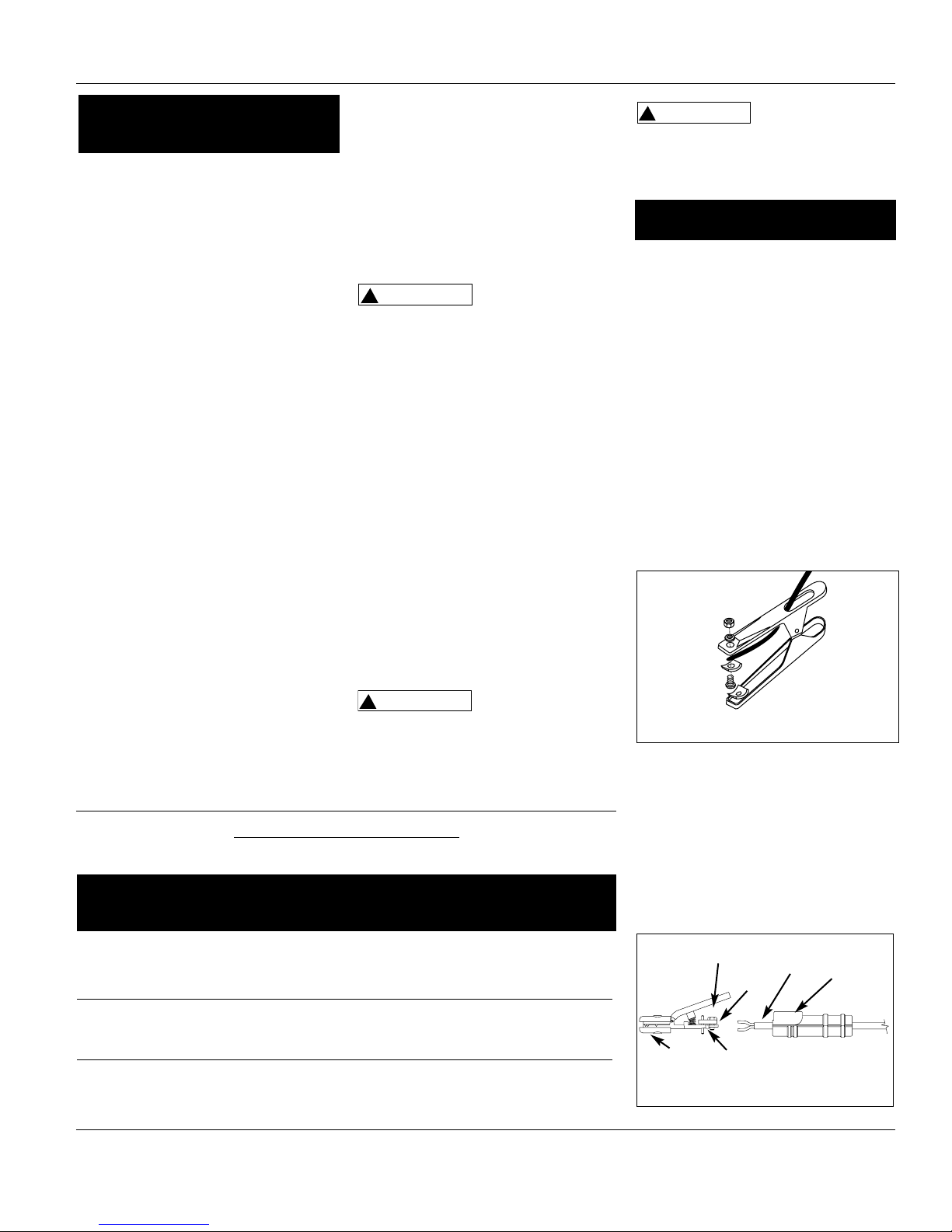
GROUND CLAMP (SEE FIGURE 1)
1. Strip 1/2” of insulation from the end
of one of the welding cables.
2. Loosen hex nuts on work clamp.
3. Insert the end of the welding cable
through clamp handle and slide the
bare wire under the clamp block.
4. Tighten the hex nuts, securing the
cable in place.
ELECTRODE HOLDER (SEE FIGURE 2)
1. Strip 1” of insulation from the end
of the other welding cable.
Separate the strands of the cable
into two sections and twist.
2. Loosen the setscrew a few turns. Do
not remove it completely. Pull
the insulated handle off of the
electrode holder, and slide it over
the welding cable.
Generator Operations
(Continued)
Welder Operations
Welder/Generator
Figure 1 - Work Clamp Assembly
Figure 2 - Electrode Holder Assembly
Shim
Cable Bolt
Welding
Cable
Electrode
Holder
Set Screw
Handle
www.chpower.com
!
CAUTION
!
WARNING
!
WARNING
Page 6
Total Cable Length* 0-20 ft (0-6 m) 20-40 ft (6-12 m) 40-60 ft (12-18 m)
Maximum Welding
Current Recommended Sizes of Copper Welding Cables
6
3. Loosen the bolt on the top of the
electrode holder.
4. Slide the bare wires from the cable
between the shim and the brass
body of the electrode holder.
5. Tighten the bolt to secure the cable
in place.
6. Slide the insulated handle onto the
electrode holder and tighten the
setscrew. Do not overtighten the
setscrew. Overtightening will
damage the insulated handle.
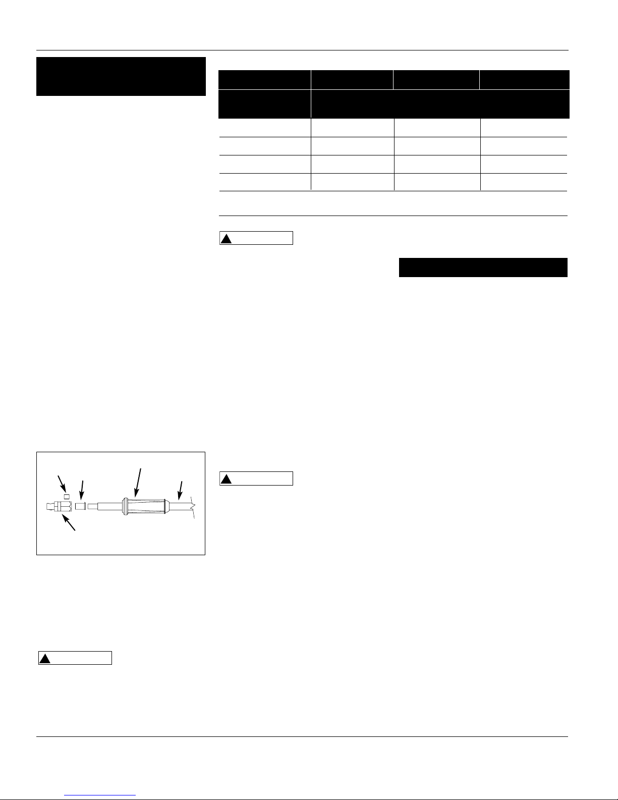
DINSE PLUGS (SEE FIGURE 3)
1. Strip 1/2” of insulation from the
opposite end of the welding cable.
2. Insert this end of the welding cable
through the dinse plug boot and
slide the bare wire into the wire
sleeve.
3. Insert the welding cable/wire sleeve
assembly into the back of the dinse
plug.
4. Tighten the set screw, securing the
cable in place.
5. Slide the boot over the hex portion
of the dinse plug.
6. Repeat for the other lead.
Welding
1. Verify that the surfaces of metals to
be joined are free from dirt, rust,
paint, oil, scale or other
contaminants. These contaminants
make welding difficult and cause
poor welds.
All persons
operating this
equipment or in the area while
equipment is in use must wear protective
welding gear including: eye protection
with proper shade (minimum shade 10),
flame resistant clothing, leather welding
gloves, and full foot protection.
If heating, welding,
or cutting materials
that are galvanized, zinc plated, lead, or
cadmium plated refer to the General
Safety Information Section for
instructions. Extremely toxic fumes are
created when these metals are heated.
2. Connect the work clamp to the
work piece. Make sure the contact is
on bare metal and not obstructed
by paint, varnish, corrosion, or nonmetallic materials.
3. Insert the exposed part of the
electrode (the end with no flux) into
the jaws of the electrode holder.
4. Set the amperage adjustment knob
to the proper amperage for the
electrode diameter. Refer to the
chart on the front panel for proper
electrode current settings.
The electrode
holder and rod are
electrically “live” (current potential)
when the engine is running.
5. Position the electrode to begin
weld, lower the welding helmet or
position the hand shield, and strike
an arc. Adjust weld amperage as
needed.
6. When finished welding, turn engine
off and store unit properly.
DUTY CYCLE/THERMOSTATIC
PROTECTION
Welder duty cycle is the percentage of
actual weld time that can occur in a ten
minute interval. For example, at a 10%
duty cycle, actual welding can occur for
one minute, then the welder must cool
for nine minutes.
Internal components of this welder are
Welder Operations
(Continued)
100 A 6 AWG (15 mm2) 6 AWG (15 mm2) 4 AWG (20 mm2)
150 A 6 AWG (15 mm2) 3 AWG (25 mm2) 2 AWG (35 mm2)
200 A 4 AWG (20 mm2) 2 AWG (35 mm2) 1 AWG (40 mm2)
250 A 3 AWG (25 mm2) 2 AWG (35 mm2) 1/0 AWG (55 mm2)
* Total cable length is the sum of the ground and electrode cable lengths
protected from overheating with an
automatic thermal switch.
INFREQUENT USAGE
If the welder/generator is used
infrequently, starting difficulty may
occur. To help prevent this, the
welder/generator should be run for
approximately 30 minutes per week.
STORAGE
If the welder/generator is not to be
used for extended periods of time, the
following pre-storage procedures
should be performed:
1. Make sure engine oil is filled to the
proper level.
2. Drain all fuel from the tank, lines,
carburetor and fuel valve.
3. Remove the spark plug, and pour
approximately one teaspoon of oil
into the spark plug hole.
4. Pull the starter cord several times to
spread the oil throughout the
cylinder.
5. Slowly pull the starter cord, until
resistance is felt. This indicates that
the piston is moving upward on the
compression cycle, and the intake
and exhaust valves are closed. (The
piston pushes a small amount of air
from the spark plug hole on
compression.)
6. Use of fuel stabilizers or antigumming agents in the fuel system
can help prevent the build up of
gum and varnish.
Whenever the welder/generator is
stored, be sure that the fuel shut-off
Operating Instructions
Figure 3 - Dinse Plug Assembly
Set
Screw
Boot
Welding
Cable
Wire
Sleeve
Dinse Plug
TABLE 3 - WELDING CABLES
www.chpower.com
Maintenance
!
WARNING
!
WARNING
!
WARNING
Page 7
7
General
This line of welding machines utilizes a
process known as Shielded Metal-Arc
Welding (SMAW). This process is used to
bond metals by heating them with an
electric arc created between the
electrode and the work piece.
Electrodes used for shielded metal arc
welding have two parts. The inner core is
a metal rod or wire that should be similar
in composition to the base metal. The
outer coating is called flux. Various types
of flux exist. Each coating is used for a
particular welding situation.
While the metal is molten, it can be
contaminated by elements in the air. This
contamination could weaken the weld.
The flux coating creates a protective
barrier called slag that protects the
molten metal from contaminants.
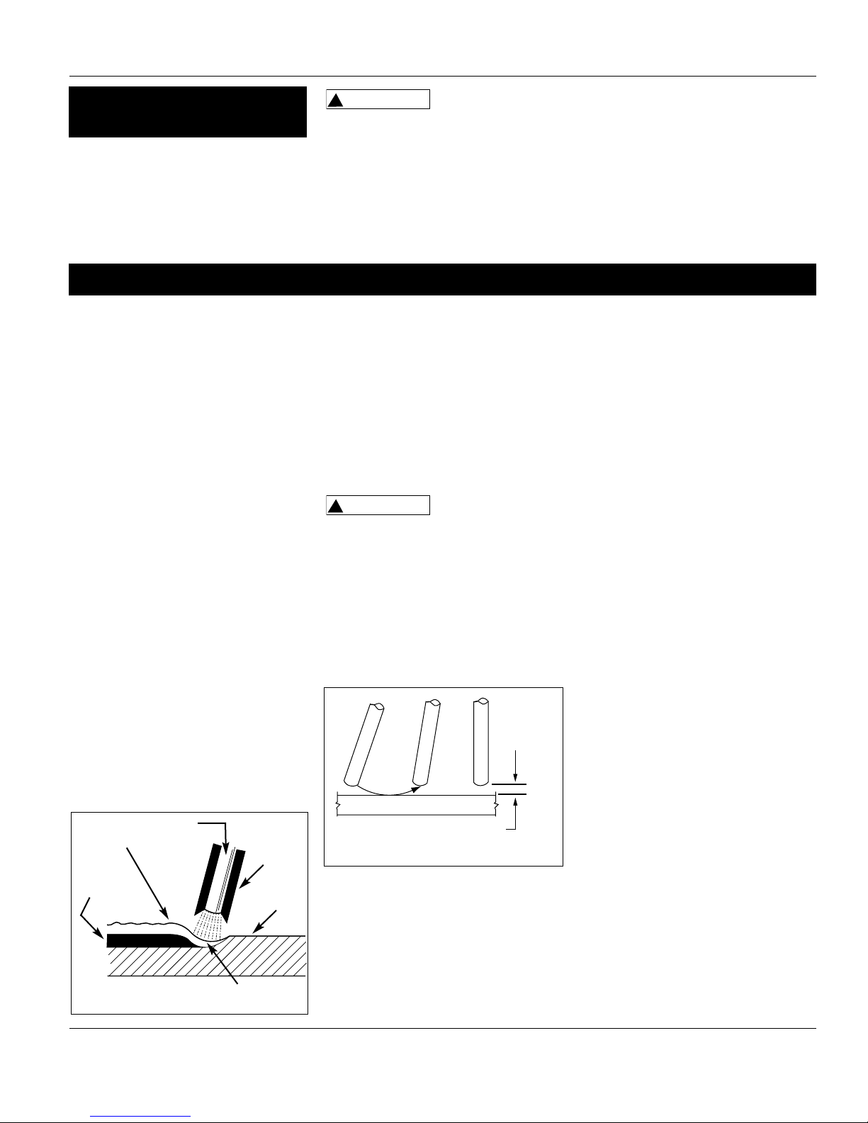
When current (amperage) flows through
the circuit to the electrode, an arc is
formed between the end of the electrode
and the work piece. The arc melts the
electrode and the work piece. The melted
metal of the electrode flows into the
molten crater and forms a bond with the
work piece as shown in Figure 4.
NOTE: Discontinue using and discard
electrodes that burn down to 1 to 2
inches from the electrode holder.
STRIKING AN ARC
Place the bare end of the electrode in the
holder. Grip the holder lightly to reduce
tiring of the hand and arm.
NOTE: Always keep the jaws of the
holder clean to insure good electrical
contact with the electrode.
Be careful not to
touch the work
piece or welding bench with the
electrode as this causes arc flashes.
The best method of striking an arc is the
scratching method. Drag the electrode at
an angle along the surface much like
striking a match. Upon contact with the
plate, lift the electrode approximately
1/16” off the surface or it will stick (See
Figure 5).
NOTE: Should the electrode stick to the
work piece, break it loose by quickly
twisting or bending at the holder while
pulling upward. If the electrode does not
break loose, disengage the electrode by
releasing it from the holder.
ELECTRODE TYPE AND SIZE
Four types of electrodes are
recommended for this welder. The
electrodes are commonly known by the
AWS (American Welding Society)
designation as follows:
1. E-6011 DEEP PENETRATING
• Flat bead with deep penetrating arc.
• For rusted or dirty mild steel general
repair work.
2. E-6013 GENERAL PURPOSE
• All position, smooth deposit rod with
low spatter.
• For all mild steel and general purpose
work.
3. E-7014 FAST FILL
• Smooth bead and fast deposition
• Ideal for joints with poor fitup and
general repair work.
4. E-7018-AC HIGH STRENGTH
• Ideal for pipes and structural
applications.
• Low hydrogen reduces porosity for a
strong weld.
NOTE: Only the E-7018-AC electrode is
recommended for use with these
welders. Other E-7018 electrodes are
designed for use with higher open
circuit voltages than these welders are
capable of producing. Recommended
electrode diameter is 3/32” or 1/8”.
Arc Welding Basics
Four basic techniques affect weld
quality. These are: amperage setting,
weld angle, arc length, and travel
speed. Proper use of these techniques is
necessary for good weld quality.
Slag
Weld
Wire
Flux
Work
Piece
Crater
Figure 4 - Weld Components
Same as Electrode Diameter
Figure 5 - Scratching Method
Welding Guidelines
Welder/Generator
Maintenance
(Continued)
valve is in the closed position.
Refer to the engine manual that
accompanies this unit for instructions
regarding maintenance of engine
components.
Never tamper with
engine speed
settings or welder/generator frequency
settings. Any governor adjustments
should be made by qualified personnel
only.
WELD CABLES
1. Check condition of weld cables and
immediately repair or replace any
cables with damaged insulation.
2. Check condition of electrode holder
insulating pieces and immediately
replace cracked or missing parts.
Every 3 months:
Replace any unreadable labels on the
welder. Use compressed air to blow all
dust and lint from the ventilation
openings.
www.chpower.com
!
WARNING
!
WARNING
1/16"
Page 8
8
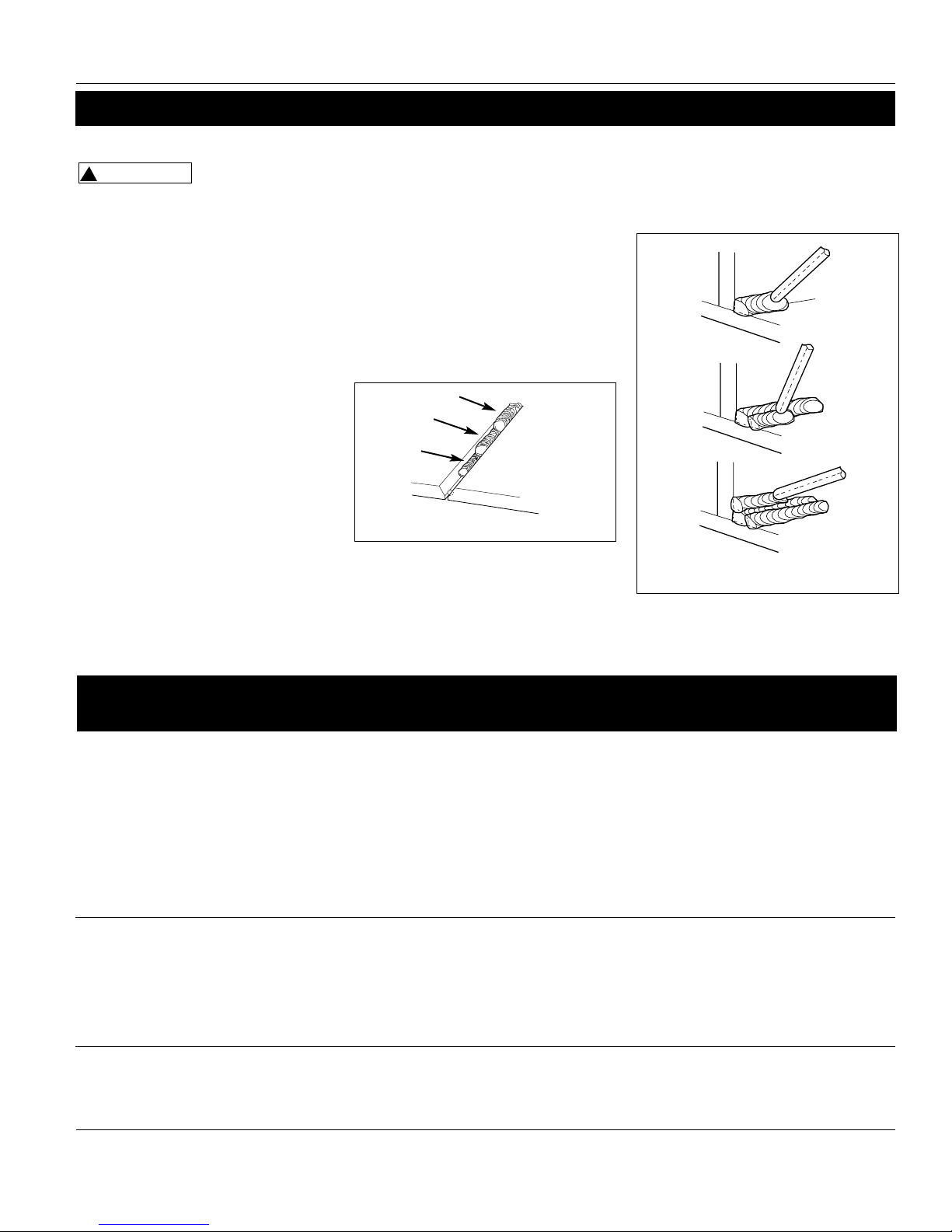
Normal Amps, Arc Length, Speed
Amperage Too Low
Amperage Too High
Arc Length Too Short
Arc Length Too Long
Speed Too Slow
Speed Too Fast
Workpiece
NOTE: Weld bead width (W)
should be approximately
twice the diameter for the
electrode rod used.
W
Figure 7 - Weld Appearance
AMPERAGE SETTING
The correct amperage involves the
adjustment of the welding machine to
the required amp setting. This is
regulated by a knob on the welder. The
amperage required depends on the size
(diameter) of electrode used and the
thickness of the work piece.
Consult specifications listed on the
welder. Excessive amps burn through
light metals and the weld bead is flat
and porous (See Figure 7). The bead
appears high and irregular if the
amperage is too low.
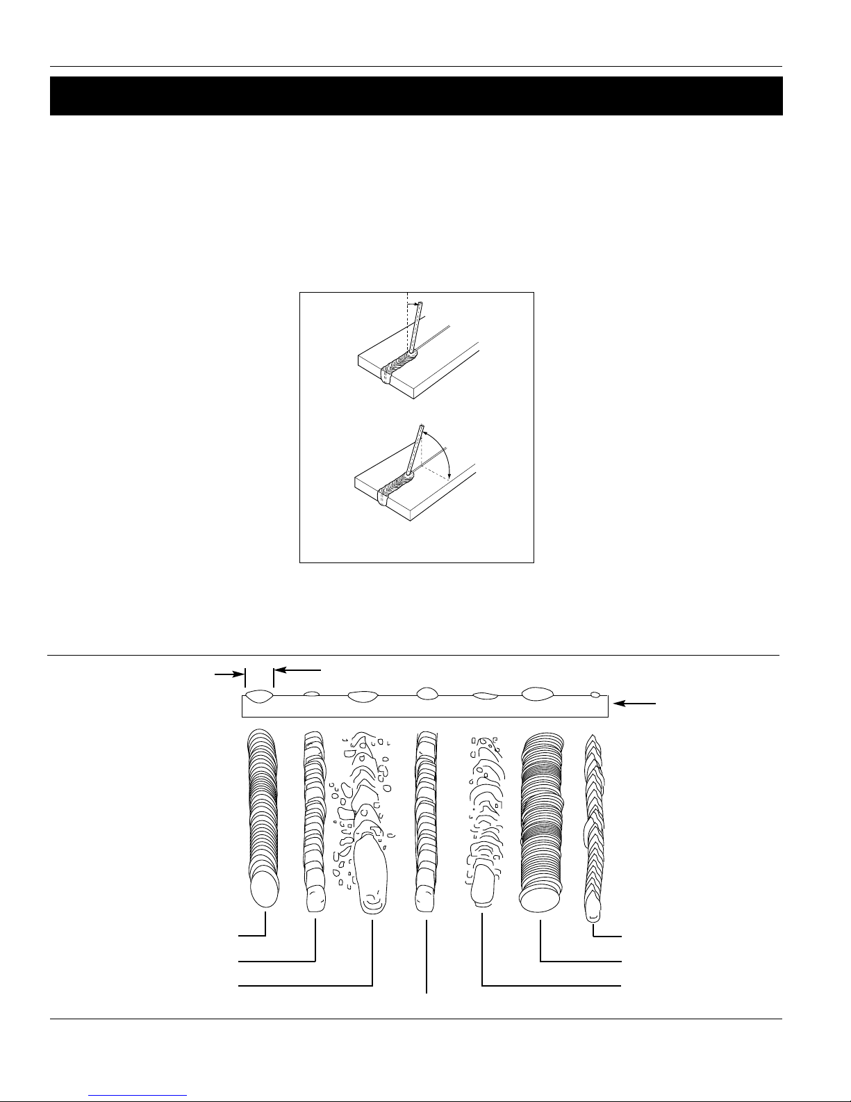
WELD ANGLE
Weld angle is the angle at which the
electrode is held during the welding
process. Using the correct angle ensures
proper penetration and bead
formation. Electrode angle involves
two positions - travel angle and work
angle (See Figure 6).
Travel angle is the angle in the line of
welding and may vary from 5º to 45º
from the vertical, depending on
welding conditions.
Work angle is the angle from
horizontal, measured at right angles to
the line of welding.
For most applications, a 45º travel
angle and 45º work angle is sufficient.
For specific applications, consult an arc
welding handbook.
NOTE: Right handed welders should
weld from left to right. Left handed
welders should weld from right to left.
The electrode should always point into
the weld puddle as shown.
ARC LENGTH
Arc length is the distance from the
work piece to the tip of the electrode,
the distance which the arc must travel.
A proper arc length is essential to
generate the heat needed for welding
(See Figure 7). An arc that is too long
produces an unstable arc, reduces
penetration, increases spatter, and
causes flat and wide beads. Too short
an arc does not create enough heat to
melt the work piece, the electrode has
a tendency to stick, penetration will be
poor, and uneven beads with irregular
ripples result. A proper arc should be
no longer than the diameter of the rod.
The sound of a proper arc is a steady,
crisp sizzle, similar to bacon frying.
TRAVEL SPEED
The travel speed is the rate at which
the electrode is moved across the weld
area (See Figure 7). When the speed is
too fast, the bead is narrow and bead
ripples are pointed as shown. When the
speed is to slow, the weld metal piles
up and the bead is high and wide. To
control travel speed, watch the width
of the weld bead (not the arc) when
welding. The weld bead is the orange,
molten metal behind the arc. The width
should be approximately twice the
diameter of the welding rod. Control
travel speed to obtain a consistent
bead width.
Welding Guidelines (Continued)
Operating Instructions
Figure 6 - Weld Angle
5o - 45
o
Travel Angle
Work Angle
www.chpower.com
Page 9
9
SLAG REMOVAL
Wear ANSI
approved safety
glasses (ANSI Standard Z87.1) and
protective clothing when removing
slag. Hot, flying debris can cause
personal injury to anyone in the area.
After completing the weld, wait for the
welded sections to cool. A protective
coating called slag now covers the weld
bead which prevents contaminants in
the air from reacting with the molten
metal. Once the weld cools to the point
that it is no longer glowing red, the
slag can be removed. Removal is done
with a chipping hammer. Lightly tap
the slag with the hammer and break it
loose from the weld bead. The final
clean-up is done with a wire brush.
When making multiple weld passes,
remove the slag before each pass.
WELDING POSITIONS
Four basic welding positions can be used;
flat, horizontal, vertical, and overhead.
Welding in the flat position is easier than
any of the others because welding speed
can be increased, the molten metal has
Figure 9 - Multiple Weld Passes
Welding Guidelines (Continued)
Welder/Generator
less tendency to run, better penetration
can be achieved, and the work is less
fatiguing.
Other positions require different
techniques such as a weaving pass,
circular pass, and jogging. A higher skill
level is required to complete these welds.
All work should be performed in the
flat position if possible. For specific
applications, consult an arc welding
handbook.
WELD PASSES
Sometimes more then one pass is
necessary to fill the joint. The root pass
is first, followed by filler passes and the
cover pass (See Figures 8 & 9). If the
Figure 8 - Weld Passes
Cover
Filler
Root
pieces are thick, it may be necessary to
bevel the edges that are joined at a 60º
angle. Remember to remove the slag
before each pass.
No output voltage
Low output voltage
with no load
High output voltage
with no load
1. Engine speed is too slow
2. Open, shorted, or incorrect wiring
3. Faulty capacitor
4. Open or shorted field windings
5. Open diodes
6. Front panel switch set incorrectly
7. Circuit breaker tripped
1. Engine speed is too slow
2. Open diodes
3. Faulty capacitor
4. Open or shorted field windings
5. Voltage setting on front panel incorrect
1. Faulty capacitor
2. Engine speed is too fast
3. Voltage setting on front panel incorrect
1. Adjust engine speed ✽
2. Referring to the wiring diagram, clean and
reconnect all wiring ✽
3. Replace capacitor ✽
4. Test winding resistance, replace field
winding if necessary ✽
5. Test diodes, replace if necessary ✽
6. Set front panel switch to generator
7. Reset circuit breaker
1. Adjust engine speed ✽
2. Test diodes, replace if necessary ✽
3. Replace capacitor ✽
4. Test winding resistance, replace field
winding if necessary ✽
5. Adjust setting on front panel
1. Replace capacitor ✽
2. Adjust engine speed ✽
3. Adjust setting on front panel
Troubleshooting Chart - Generator
Symptom Possible Cause(s) Corrective Action
www.chpower.com
!
WARNING
Page 10

10
Operating Instructions
✽ These diagnostic and repair procedures should be performed by an authorized service center.
Troubleshooting Chart - Generator (Continued)
Symptom Possible Cause(s) Corrective Action
Low output voltage
under load
Erratic output voltage
Noisy operation
1. Open diode
2. Engine speed too slow at full load
3. Excessive load applied
4. Voltage setting on front panel incorrect
1. Unbalanced engine
2. Dirty, corroded, or loose wiring
connection
3. Unstable load applied
1. Loose welder/generator or engine bolt
2. Short circuit in welder/generator field or
load
3. Faulty bearing
1. Test diodes, replace if necessary ✽
2. Adjust engine speed ✽
3. Reduce the applied load
4. Adjust setting on front panel
1. Refer to engine manual
2. Referring to the wiring diagram, clean and
reconnect all wiring ✽
3. Remove all loads, then apply each one
individually to determine which one is
causing erratic function
1. Tighten all mountings
2. Test winding resistance, replace field
winding if necessary ✽
Test load devices for shorts. Replace
defective load device.
3. Replace bearing
1. Check work clamp, cable and connection to work
piece. Check electrode cable and clamp
2. Check all welder external connections
3. Set front panel switch to weld
4. Referring to the wiring diagram, clean and
reconnect all wiring ✽
5. Replace capacitor ✽
6. Test winding resistance, replace field winding if
necessary ✽
7. Test diodes, replace if necessary ✽
1.Avoid contact with work piece
2. Make sure clothing and work area are dry
1. Verify that electrode is for alternating current (AC)
2. Use smaller diameter electrode
3. Verify proper grounding. (No paint, varnish or
corrosion)
4. Adjust engine speed
Troubleshooting Chart - Welder
Symptom Possible Cause(s) Corrective Action
1. Inadequate current at electrode
2. Poor connections at welder
3. Front panel switch set incorrectly
4. Open, shorted, or incorrect wiring
5. Faulty capacitor
6. Open or shorted field windings
7. Open diodes
1. Accidental contact with work
piece
2. Current leakage caused by moist
clothing or work area
1. Wrong type of electrode.
2. Electrode diameter too large
3. Work piece not properly
grounded
4. Engine speed is too slow
Welder runs but does not
weld
Welder gives trickle
shocks
Arc difficult to strike
✽ These diagnostic and repair procedures should be performed by an authorized service center.
www.chpower.com
Page 11
11
Troubleshooting Chart - Welds
Symptom Possible Cause(s) Corrective Action
Bead is intermittently
too thin or too thick
Ragged depressions
at edge of weld
Weld bead does not
penetrate base metal
Electrode sticks to
workpiece
Electrodes sputter
and stick
1. Inconsistent travel speed
2. Output amp setting incorrect
1. Travel speed too fast
2. Arc length too short
3. Output amp setting too high
1. Inconsistent travel speed
2. Output amp setting too low
3. Electrode diameter too large
1. Arc length short
2. Amp setting low
3. Incorrect electrode
Damp electrodes
1. Carefully watch and control the width of the molten weld
bead
2. Adjust output amp setting or change to smaller diameter
electrode
1. Watch orange molten weld puddle and control bead width
2. Practice running electrode across workpiece with welder OFF
3. Reduce output amp setting
1. Decrease and maintain constant travel speed
2. Increase output amp setting
3. Change to smaller diameter electrode
1. Lift electrode to correct arc length as soon as arc is struck
2. Increase amp setting or change to smaller diameter
electrode
3. Verify electrode is suitable for 62.5 V open circuit voltage
Use dry electrodes and store in dry location
Welder/Generator
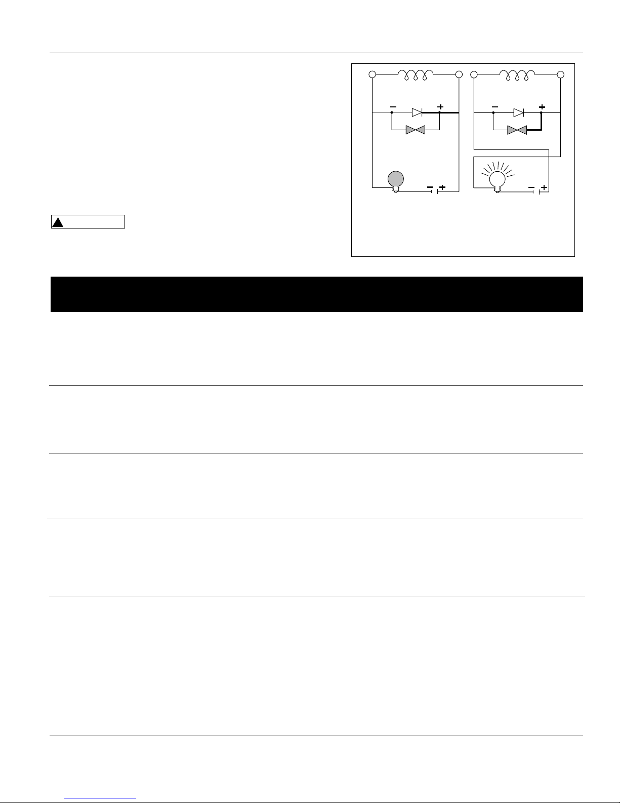
TESTING WELDER/GENERATOR DIODES
The following method eliminates the need to disconnect the diodes
from the welder/generator wiring.
1. Use a 12 Volt battery and automotive lamp (Type 5001) to test
the diodes in the welder/generator.
2. Connect the battery and lamp as shown in Figure 10.
3. If the diodes are operating properly, the lamp illuminates
brightly when the battery polarity is correct, and goes dim when
battery polarity is reversed.
4. If there is no change in lamp brightness when polarity is
reversed, the diodes must be replaced.
For testing of rotor, stator, or field windings,
consult an authorized service center.
Figure 10 - Diode Test Procedure
www.chpower.com
!
WARNING
Lamp Off
Lamp On
Page 12

12
AC or Alternating Current - electric
current that reverses direction
periodically. Sixty cycle current travels in
both directions sixty times per second.
Arc Length - the distance from the end
of the electrode to the point where the
arc makes contact with the work surface.
Base Metal - the material to be welded.
Butt Joint - a joint between two
members aligned approximately in the
same plane.
Crater - a pool, or pocket, that is formed
as the arc comes in contact with the base
metal.
DC or Direct Current - electric current
which flows only in one direction. The
polarity (+ or -) determines which
direction the current is flowing.
DC Reverse Polarity - occurs when the
electrode holder is connected to the
positive pole of the welding machine.
Reverse Polarity directs more heat into
melting the electrode rather than the
work piece. It is used on thinner
material.
DC Straight Polarity - occurs when the
electrode holder is connected to the
negative pole of the welding machine.
With straight polarity more heat is
directed to the work piece for better
penetration on thicker material.
Electrode - a coated metal wire having
approximately the same composition as
the material being welded.
Fillet Weld - approximately a triangle in
cross-section, joining two surfaces at
right angles to each other in a lap, T or
corner joint.
Flux - a coating, when heated, that
produces a shielding gas around the
welding area. This gas protects the
parent and filler metals from impurities
in the air.
Flux Cored Arc Welding (FCAW) - also
called Gasless, is a welding process used
with a wire-feed welding machine. The
weld wire is tubular with flux material
contained inside for shielding.
Gas Metal Arc Welding (GMAW) also called MIG, is a welding process
used with a wire feed welding machine.
The wire is solid and an inert gas is used
for shielding.
Gas Tungsten Arc Welding (GTAW) also called TIG, is a welding process used
with welding equipment with a high
frequency generator. The arc is created
between a non-consumable tungsten
electrode and the work piece. Filler
metal may or may not be used.
Lap Joint - a joint between two
overlapping members in parallel planes.
Open Circuit Voltage (OCV) - the
voltage between the electrode and the
work clamp of the welding machine
when no current is flowing (not
welding). The OCV determines how
quickly the arc is struck.
Overlap - occurs when the amperage is
set too low. In this instance, the molten
metal falls from the electrode without
actually fusing into the base metal.
Porosity - gas pockets, or cavities,
formed during weld solidification. They
weaken the weld.
Penetration - the depth into the work
piece that has been heat effected by the
arc during the welding process. A good
weld achieves 100% penetration
meaning that the entire thickness of the
work piece has been heated and
resolidified. The heat effected area
should be easily seen on the opposite
side of the weld.
Shielded Metal Arc Welding (SMAW)
- also called Stick, is a welding process
that uses a consumable electrode to
support the arc. Shielding is achieved by
the melting of the flux coating on the
electrode.
Slag - a layer of flux soot that protects
the weld from oxides and other
contaminants while the weld is
solidifying (cooling). Slag should be
removed after weld has cooled.
Spatter - metal particles thrown from
the weld which cool and harden on the
work surface. Spatter can be minimized
by using a spatter resistant spray on the
work piece before welding.
Tack Weld - weld made to hold parts in
proper alignment until final welds are
made.
Travel Angle - the angle of the
electrode in the line of welding. It varies
from 5º to 45º depending on welding
conditions.
T Joint - made by placing the edge of
one piece of metal on the surface of the
other piece at approximately a 90º
angle.
Undercut - a condition that results
when welding amperage is too high.
The excessive amperage leaves a groove
in the base metal along both sides of the
bead which reduces the strength of the
weld.
Weld Pool or Puddle - a volume of
molten metal in a weld prior to its
solidification as weld metal.
Weld Bead - a narrow layer or layers of
metal deposited on the base metal as
the electrode melts. Weld bead width is
typically twice the diameter of the
electrode.
Work Angle - the angle of the electrode
from horizontal, measured at right
angles to the line of welding.
Glossary of Welding Terms
www.chpower.com
Operating Instructions
Page 13
13
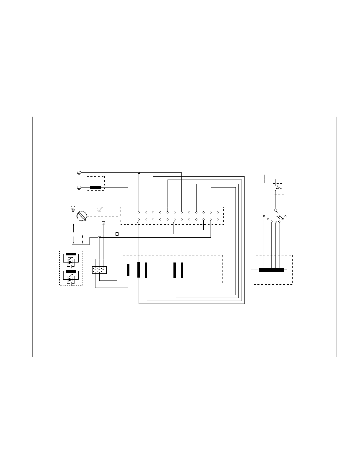
Welding
Impedance
Gen. Weld.
Rotor
Red
White
Brown
Battery Charger
12V AC
Blue
Brown
GreyRed
BlackWhite
Yellow
Green
Main Winding
Brown
Red
White
Green
Generator/Welder
Power Switch
2 4 6 8 10 12 14 16 18 20 22 24
135 7911131517192123
Capacitor
Thermal Trip
(Fitted Inside
the Windings)
Violet
Black
Blue
Grey
Red
Brown
Yellow
Orange
Auxiliary Winding
Welding Current
and Generator
Voltage Selector
R/L1
White
Orange
115V
230V
Blue
Electrode
Holder
Ground
Clamp
1
2
7
6
3
4
5
Adjustable
Figure 11 - Wiring Diagram - AC Welder/Generator
www.chpower.com
Welder/Generator
Page 14

Operating Instructions
Limited Warranty
1. DURATION: One year from the date of purchase by the original purchaser. Units used for rental or commercial purposes are
warranted for 90 days from date of purchase.
2. WHO GIVES THIS WARRANTY (WARRANTOR):
The Campbell Group / A Scott Fetzer Company
100 Production Drive
Harrison, Ohio, 45030
Telephone: (513) 367-4811.
3. WHO RECEIVES THIS WARRANTY (PURCHASER): The original purchaser (other than for purposes of resale) of the Campbell
Hausfeld product.
4. WHAT PRODUCTS ARE COVERED BY THIS WARRANTY: Any Campbell Hausfeld portable welder/generator supplied or
manufactured by Warrantor.
5. WHAT IS COVERED UNDER THIS WARRANTY: Defects on material and workmanship which occur within the duration of the
warranty period.
6. WHAT IS NOT COVERED UNDER THIS WARRANTY:
A. Implied warranties, including those of merchantability and FITNESS FOR A PARTICULAR PURPOSE ARE LIMITED TO ONE YEAR
FROM THE DATE OF ORIGINAL PURCHASE. Some states do not allow limitations on how long an implied warranty lasts, so the
above limitations may not apply to you.
B. ANY INCIDENTAL, INDIRECT, OR CONSEQUENTIAL LOSS, DAMAGE, OR EXPENSE THAT MAY RESULT FROM ANY DEFECT,
FAILURE, OR MALFUNCTION OF THE CAMPBELL HAUSFELD PRODUCT. Some states do not allow the exclusion or limitation of
incidental or consequential damages, so the above limitation or exclusion may not apply to you.
C. Any failure that results from an accident, purchaser’s abuse, neglect or failure to operate products in accordance with
instructions provided in the owner’s manual(s) supplied with product.
D. Pre-delivery service, i.e. assembly, oil or lubricants, and adjustment.
E. Normal adjustments which are explained in the owner’s manual(s) provided with the product, i.e. belts, pressure switch.
F. Items or service that are normally required to maintain the product, i.e. lubricants, filters and gaskets.
G. Electric motor and gasoline engine components are expressly excluded from coverage under this limited warranty. Such
components should be returned by the purchaser to the original manufacturer or to its authorized repair stations for service.
7. RESPONSIBILITIES OF WARRANTOR UNDER THIS WARRANTY: Repair or replace, at Warrantor’s option, products or
components which have failed within duration of the warranty period.
8. RESPONSIBILITIES OF PURCHASER UNDER THIS WARRANTY:
A. Deliver or ship the Campbell Hausfeld product or component to the nearest Campbell Hausfeld Authorized Service Center.
Freight costs, if any, must be borne by the purchaser.
B. Use reasonable care in the operation and maintenance of the products as described in the owner’s manual(s).
9. WHEN WARRANTOR WILL PERFORM REPAIR OR REPLACEMENT UNDER THIS WARRANTY:
A. Repair or replacement will be scheduled and serviced according to the normal work flow at the servicing location, and
depending on the availability of replacement parts.
B. If the purchaser does not receive satisfactory results from the Authorized Service Center, the purchaser should contact the
Campbell Hausfeld Product Service Department (see paragraph 2).
This Limited Warranty gives you specific legal rights and you may also have other rights which vary from state to state.
www.chpower.com
Page 15

IN952500AV 3/01
Instructions D’Utilisation
Soudeur/Génératrice
Ces modèles sont alimentés par des
moteurs à quatre temps à
refroidissement par air et conçus pour
fonctionner à un tr/min maximum et
donner une puissance en watts
continue tel qu’indiquée. Sur certains
modèles, un indicateur d’huile bas est
fourni pour protéger le moteur. Cette
caractéristique est d’habitude
attribuée avec des modèles à
fonctionnement prolongé.
L’alternateur a un protecteur
thermique. Pour faire fonctionner ce
modèle comme soudeur ou
génératrice, positionner l’interrupteur
sur le panneau avant en conséquence.
Lors du déballage, l’examiner
soigneusement pour rechercher toute
trace de dommage susceptible de
s’être produit en cours de transport.
Serrer tous raccords, boulons, etc.,
avant de faire fonctionner le modèle.
Composer le 1-800-746-5641 s’il y a des
pièces qui manquent.
Danger
vous
avertis d’un danger qui RÉSULTERA en
blessure grave ou la mort.
Avertissement vous avertis d’un
danger qui POURRA résulter en
blessure grave ou la mort.
Attention
vous avertis d’un danger qui POURRA
résulter en blessure.
Avis
vous
avertis d’informations importantes qui
aidera à empêcher le dommage à
l’équipement.
● Avant de démarrer ou
d’entretenir le modèle
soudeur/génératrice, lire
et comprendre toutes les instructions.
Manque de respecter les précautions
de sécurité ou les instructions peut
résulter en panne d’équipement
et/ou en blessures personnelles
graves ou en mort. Les instructions
de moteur de ces modèles sont dans
un manuel séparé. Conserver tous les
manuels comme référence.
● Ne jamais utiliser ce modèle
soudeur/génératrice pour une
application autre que celle spécifiée
par le fabricant. Ne jamais faire
fonctionner ce modèle
soudeur/génératrice dans des
conditions qui ne sont pas
approuvées par le fabricant. Ne
jamais essayer de modifier ce modèle
soudeur/génératrice afin de
performer d’une façon autre que
celle conçue par le fabricant.
● Pour l’entretien et la réparation,
utiliser seulement les produits et les
pièces recommandées par le
fabricant.
● S’assurer que le modèle
soudeur/génératrice soit mis à la terre
correctement à une source externe
avant le fonctionnement Se référer à
la section “Instructions de Mise à la
Terre” pour la marche à suivre
correcte concernant la mise à la terre.
● S’assurer que le modèle
soudeur/génératrice soit utilisé
seulement par des personnes qui ont
lus et compris ces instructions.
● S’assurer que le modèle
soudeur/génératrice soit placé sur
une surface plate avant et pendant le
fonctionnement. Le
soudeur/génératrice ne doit pas
glisser ni se déplacer pendant le
fonctionnement.
● Garder toutes personnes à l’écart du
modèle soudeur/génératrice pendant
le fonctionnment.
● Ne pas permettre que les personnes
qui portent des vêtements et de la
bijouterie démarrent ou fassent
fonctionner le modèle
soudeur/génératrice. Les vêtements
flottants et la bijouterie peuvent se
prendre dans les pièces mouvantes,
endommageant l’équipement et/ou
causant des blessures personnelles.
● Garder toutes personnes à l’écart des
pièces mouvantes ou qui se
réchauffent pendant le
fonctionnement.
● S’assurer que tous les appareils
alimentés soient hors circuit avant de
les brancher au modèle
soudeur/génératrice.
● Garder le modèle
soudeur/génératrice propre et en bon
état de marche à tout temps.
Ne jamais faire fonctionner
ce modèle soudeur/
génératrice dans un endroit
explosif, inflammable ou mal-aéré.
● S’assurer que tous les outils et
appareils soient en bon état de
marche et mis à la terre
correctement. Utiliser des appareils
qui ont un cordon d’alimentation à
trois broches. Si vous utilisez un
cordon prolongateur, s’assurer qu’il
ait trois broches pour la mise à la
terre correcte.
Ne pas
faire
fonctionner ce modèle soudeur/
génératrice sur une surface trempe ni
dans la pluie.
Couper
le moteur
et déconnecter le fil de la bougie
d’allumage avant de procéder à
l’entretien du modèle.
● Utiliser seulement de l’essence sans
plomb. Ne jamais faire le plein
d’essence pendant que le moteur
fonctionne. Faire attention de ne
pas renverser pendant que vous
faites le plein d’essence. S’assurer
que le capuchon du réservoir à
essence soit bien placé avant de
démarrer le moteur. Nettoyer les
déversements avant de démarrer le
moteur. Permettre que le moteur
se refroidisse pendant au moins
deux minutes avant de faire le plein
d’essence.
© 2001 Campbell Hausfeld
Description
Déballage
Généralités Sur La Sécurité
S’il vous plaît lire et conserver ces instructions. Lire attentivement avant de monter, installer, utiliser ou de procéder à l’entretien du produit
décrit. Se protéger ainsi que les autres en observant toutes les instructions de sécurité, sinon, il y a risque de blessure et/ou dégâts matériels!
Conserver ces instructions comme référence.
BUILT TO LAST
TM
!
DANGER
!
AVERTISSEMENT
!
ATTENTION
AVIS
MANUEL
!
AVERTISSEMENT
!
AVERTISSEMENT
!
DANGER
Page 16

16 Fr
Instructions D’Utilisation
● Ce modèle soudeur/génératrice
peut être utilisé comme source
alternative en cas d’urgence. Dans
ce cas, un inverseur manuel doit
être installé entre le compteur
d’électricité et la boîte de
dispersion. Cet interrupteur devrait
être installé par un électricien
autorisé.
Ne jamais
mélanger
de l’huile avec de l’essence pour ce
moteur. Ceci est un moteur à quatre
temps conçu pour fonctionner
uniquement avec de l’essence. L’huile
est utilisé seulement pour graisser le
moteur.
Toujours garder un
extincteur d’incendie à la
portée pendant le soudage à
l’arc.
● Seules des personnes qualifiées
doivent performer l’installation,
l’entretien, la réparation et le
fonctionnement de cet équipement
en conformément aux codes locaux,
provinciaux et nationaux.
L’utilisation incorrecte des
soudeurs à l’arc électriques
peut causer des secousses électriques,
des blessures et la mort! Respecter
toutes les précautions décrites dans ce
manuel pour réduire le risque de
secousse électrique.
● Vérifier que les pièces détachées du
soudeur à l’arc soient propres et en
bon état de marche avant de faire
fonctionner le soudeur. S’assurer
que l’isolation sur les câbles, porteélectrodes et cordons
d’alimentation ne soient pas
endommagés. Toujours réparer ou
remplacer des pièces endommagées
ou usées avant de faire fonctionner
le soudeur. Toujours garder les
panneaux de soudage, les écrans
etc. en place pendant le
fonctionnement du soudeur.
● Toujours porter des vêtements
protecteurs secs, des gants de
soudage et des chaussures isolées.
● Toujours faire fonctionner le
soudeur dans un endroit propre, sec
en bien aéré. Ne pas faire
fonctionner le soudeur dans un
endroit humide, trempe, pluvieux
ou mal-aéré.
● S’assurer que l’objet de travail soit
bien supporté et mis à la terre avant
de commencer le soudage à l’arc.
● Étendre le câble à soudage enroulé
pour empêcher le surchauffage et
d’endommager l’isolation.
Ne
jamais
immerger l’électrode ou le porteélectrode dans l’eau. Si le soudeur
se mouille, s’assurer qu’il soit
complètement propre et sec avant
d’essayer de l’utiliser!
● Toujours mettre l’équipement hors
circuit avant de le déplacer.
● Toujours fixer le conducteur de
travail en premier.
● Vérifier que l’objet de travail soit
bien mis à la terre.
● Toujours mettre l’équipement de
soudage à l’arc hors circuit (off)
lorsqu’il est au repos et enlever
l’électrode du porte-électrode.
● Ne jamais permettre que les parties du
corps touchent l’électrode et la pièce
de terre ou l’objet de travail mis à la
terre en même temps.
● Les positions et conditions de
soudage difficiles peuvent poser des
dangers électriques. Lorsque vous
êtes accroupis, à genou ou élevés,
s’assurer d’isoler toutes pièces
conductives, porter les vêtements
protecteurs appropriés et prendre des
précautions pour s’empêcher de
tomber.
● Ne jamais essayer d’utiliser cet
équipement aux réglages de
courant ou aux facteurs d’utilisation
supérieurs à ceux spécifiés sur les
étiquettes de l’équipement.
● Ne jamais utiliser un soudeur à l’arc
pour dégeler des tuyaux gelés.
Des étincelles volantes et le
métal chaud peuvent causer
des blessures. Pendant le
refroidissement des soudures, la scorie
peut être dégagée. Prendre toutes les
précautions décrites dans ce manuel
pour diminuer le risque de blessures
causées par les étincelles volantes et le
métal chaud.
● Porter un écran facial approuvé par
ANSI ou des lunettes de sécurité
avec des écrans latéraux pendant le
burinage ou le meulage des pièces
en métal.
● Porter des bouchons d’oreilles lors
du soudage aérien afin d’empêcher
que la scorie ou que les
éclaboussures tombent dans les
oreilles.
Les opérations de soudage à
l’arc électrique produisent
une lumière et une chaleur
intense ainsi que des rayons
ultraviolets. (UV). Cette lumière
intense et les rayons UV peuvent causer
des blessures aux yeux et à la peau.
Prenez toutes les précautions décrites
dans le manuel pour diminuter la
possibilité de blessures aux yeux et à la
peau.
● Toutes personnes qui font
fonctionner cet équipement ou qui
sont dans l’endroit lorsque
l’équipement est en marche doivent
porter des vêtements de soudage
protecteurs, y compris un casque ou
un écran avec au moins une
puissance de 10, des vêtements
résistant aux flammes, des gants de
soudage en cuir, et de la pleine
protection pour les pieds.
Ne
jamais
regarder aux opérations de soudage
à l’arc sans protection oculaire telle
que décrite ci-dessus. Ne jamais
utiliser une lentille filtrante ombrée
qui est fêlée, cassée ou classifiée
moins que 10. Avertir les autres
autours de ne pas regarder à l’arc.
Les opérations de soudage à
l’arc peuvent causer des
étincelles et chauffer le
métal à des températures qui
peuvent causer des brûlures
graves! Utiliser des gants et des
vêtements protecteurs lors des
opérations métallurgiques. Prenez
toutes les précautions décrites dans le
manuel afin de diminuer le risque de
brûler la peau et les vêtements.
● S’assurer que toutes les personnes
dans l’endroit de soudage soient
protégées de la chaleur, des
étincelles et des rayons ultraviolets.
Utiliser d’autres écrans faciales et
barrières résistantes aux flammes au
besoin.
● Ne jamais toucher les objets de
travail avant qu’ils ne soient
complètement refroidis.
La chaleur et les étincelles
produites lors du soudage à
l’arc électrique et autres
opérations métallurgiques peuvent
allumer les substances inflammables et
matériaux explosifs! Prenez toutes les
précautions décrites dans le manuel
pour diminuer la possibilité de flammes
ou d’explosion.
● Enlever tous matériaux
inflammables jusqu’à 35 pi (10.7
mètres) de l’arc de soudage. S’il
n’est pas possible, bien recouvrir les
Généralités Sur La
Sécurité (Suite)
!
ATTENTION
!
AVERTISSEMENT
!
AVERTISSEMENT
!
DANGER
!
AVERTISSEMENT
!
AVERTISSEMENT
!
AVERTISSEMENT
!
AVERTISSEMENT
!
AVERTISSEMENT
Page 17

17 Fr
matériaux inflammables avec des
covercles ingnifugés.
● Prenez les précautions pour
s’assurer que les étincelles volantes
et la chaleur ne causent pas de
flammes dans des endroits cachés,
fissures, derrière les cloisons, etc.
Risque d’incendie! Ne pas
souder les boîtes ou pipes qui
contiennent ou qui ont déjà
contenu des matériaux inflammables,
ou des gaz ou liquides combustibles.
Le soudage à l’arc des boîtes
ou des cylindres fermés tels
que les réservoirs ou les
cylindres peuvent causer une explosion
s’ils ne sont pas bien aérés! Vérifier
que tous les cylindres ou boîtes qui
doivent être soudés aient un trou
suffisament grand pour aérer afin que
les gaz en expansion peuvent être
relâchés.
Ne pas respirer les vapeurs
produites lors du soudage à
l’arc. Les vapeurs sont
dangereuses. Si l’endroit de soudage
ne peut pas être bien aéré, s’assurer
dutiliser un respirateur qui vous fournit
de l’air.
● Garder la tête et le visage hors des
vapeurs de soudage.
● Ne pas performer du soudage à l’arc
électrique sur des métaux galvanisés
ou plaqués de cadmium, qui
contiennent du zinc, du mercure ou
du berylium sans suivre les
précautions suivantes:
a. Enlever l’enrobement du métal de
base.
b. S’assurer que l’endroit de
soudage soit bien aéré.
c. Utiliser un respirateur pour vous
fournir de l’air.
Des vapeurs extrêmement toxiques
sont crées lorsque ces métaux sont
chauffés.
Le champ électromagnétique
qui est crée pendant le
soudage à l’arc peut entrer en conflit
avec le fonctionnement de plusieurs
appareils électriques tels que les
stimulateurs cardiaques. Les personnes
qui utilisent ces appareils devraient
consulter leur médecin avant de
performer le soudage à l’arc.
● Faire passer l’électrode et les câbles
de service ensembles et fixer avec
du ruban là où possible.
● Ne jamais s’envelopper les câbles de
soudage autour du corps.
● Toujours positionner l’électrode et
les conducteurs de travail afin qu’ils
soient du même côté du corps.
● S’exposer aux champs
électromagnétiques pendant le
soudage peut avoir d’autres
conséquences inconnues reliées à la
santé.
Toujours
s’assurer
que l’endroit de travail soit sécure et
libre d’hasards (étincelles, flammes,
métal incandescent ou scorie) avant
de partir. S’assurer que l’équipement
soit hors circuit et que l’électrode
soit enlevé. S’assurer que les câbles
soit enroulés et hors portée.
S’assurer que tout métal et scorie
soit refroidit.
NORMES DE SÉCURITÉ ADDITIONNELLES
Norme ANSI Z49.1 de l’ American
Welding Society, 550 N.W. LeJune Rd.
Miami, FL 33126
Safety and Health Standards
(Normes de Sécurité et de Santé)
OSHA 29 CFR 1910, du Superintendent
of Documents, U.S. Government
Printing Office, Washington, D.C. 20402
National Electrical Code (Code
Électrique National)
Norme NFPA 70, du National Fire
Protection Association, Batterymarch
Park, Quincy, MA 02269
Safe Handling of Compressed Gases
in Cylinders (Manipulation Sûr des
Gaz Comprimés en Cylindres)
CGA Pamphlet P-1, du Compressed Gas
Association, 1235 Jefferson Davis
Highway, Suite 501, Arlington, VA
22202
Code for Safety in Welding and
Cutting (Code de Sécurité pour le
Soudage et le Coupage)
Norme CSA W117.2, du Canadian
Standards Association, Standards Sales,
178 Rexdale Boulevard, Rexdale,
Ontario, Canada M9W 1R3
Cutting And Welding Processes
(Procédés de Coupage et de
Soudage)
Norme NFPA 51B, du National Fire
Protection Association, Batterymarch
Park, Quicy, MA 02269
Safe Practices For Occupational And
Educational Eye And Face
Protection (Règlements
Professionnels et D’Éducation de
Sécurité pour la Protection des
Yeux et du Visage)
Norme ANSI Z87.1, de l’American
National Standards Institute, 1430
Broadway, New York, NY 10018
Se référer aux Material Safety Data
Sheets (Données De Sécurité) et les
instructions du fabricant pour métaux,
électrodes, enduits et produits pour le
nettoyage.
EMPLACEMENT
Un bon emplacement peut augmenter
la performance, la fiabilité et
l’espérance de vie du soudeur à l’arc
d’une façon significante.
● Pour les meilleurs résultats, placer le
modèle soudeur/génératrice dans
un environnement propre et sec. La
poussière et le débris dans le
modèle absorbent l’humidité et
augmentent l’usure des pièces
mouvantes.
● Entreposer les électrodes dans un
endroit propre et sec avec une
humidité basse afin de préserver
l’enrobement de flux.
PRÉ-FONCTIONNEMENT
1. Vérifier le niveau d’huile du moteur.
L’huile N’EST PAS mélangée avec de
l’essence, par contre une source
adéquate d’huile est nécessaire pour
le graissage correct du moteur. Se
référer au Manuel du Moteur pour le
SAE, API et les spécifications de
remplissage. Le modèle est livré sans
huile dans le moteur.
2. Utiliser un interrupteur pour protéger
contre un dérangement due à une
mise à la terre accidentelle (DDFT)
L’usage d’une DDFT est fortement
encouragé. Ces interrupteurs
peuvent diminuer de façon
spectaculaire le risque de blessures
dans le cas de secousse électrique.
Pour installer un DDFT, le fil neutre du
modèle soudeur/génératrice doit être
mis à la terre de façon interne au bâti
du modèle soudeur/génératrice, et le
bâti doit être mis à la terre
correctement à la terre.
Un
interrupteur DDFT peut ne pas
fonctionner si utilisé sur un modèle
soudeur/génératrice qui n’est pas mis
à la terre! Se référer à la section Mise
à la Terre pour les étapes de la mise à
la terre du modèle
soudeur/génératrice.
3. Lorsque vous installez un DDFT,
s’assurer de suivre tous les règlements
locaux et nationaux. Si vous n’êtes
pas certains des règlements et des
procédures, consultez un technicien
électrique (autorisé ou certifié)
MISE À LA TERRE
1. Utiliser la borne de terre et l’écrou à
oreilles sur le bâti du modèle
soudeur/génératrice pour connecter
le modèle à une source de terre
convenable. Bien fixer la borne
d’attache du fil de terre à la borne de
terre sur le bâti du modèle
soudeur/génératrice. Serrer la
rondelle et l’écrou à oreilles sur le
haut de la borne d’attache du fil de
terre.
2. Le fil de terre devrait être un fil de
calibre #8. Ne pas utilier un fil avec un
numéro de calibre supérieur. Un
numéro de calibre supérieur indique
Généralités Sur La
Sécurité (Suite)
Soudeur/Génératrice
Opération Générale
!
AVERTISSEMENT
!
AVERTISSEMENT
!
AVERTISSEMENT
!
AVERTISSEMENT
!
ATTENTION
!
ATTENTION
Page 18

18 Fr
Instructions D’Utilisation
un fil plus mince qui ne fournira
peut-être pas une mise à la terre
suffisante.
3. L’autre bout du fil de terre doit être
bien fixé à une source de terre
approuvée.
Les sources suivantes sont approuvées
par le Code Électrique National. D’autres
sources pourraient être acceptables. Se
référer au Code Électrique National et les
règlements locaux pour de l’information
supplémentaire concernant les sources.
Si vous n’êtes pas certain des règlements
ou des procédures, consultez un
technicien qualifié (autorisé ou certifié).
a. Un tuyau d’eau souterrain au
moins 10 pieds (3 m) de longueur
b. Un tuyau non-corrosif souterrain
au moins huit pieds (2,4 m) de
longueur et 3/4 po (19,1 mm) de
diamètre
c. Une tige souterraine en acier ou en
fer au moins huit pieds (2,4 m) de
longueur et 5/8 po (15,9 mm) de
diamètre
d. Une tige non-ferreuse au moins
huit pieds (2,4 m) de longueur, 1/2
po (12,7 mm) de diamètre et
approuvée pour la mise à la terre.
N’importe quel tuyau ou tige utilisée
pour la mise à la terre doit être enfoncé
huit pieds (2,4 m) ou enterré dans le
fossé le plus profond possible.
DÉMARRAGE
1. Enlever toutes charges électriques du
modèle soudeur/génératrice.
2. Tourner la soupape d’arrêt de
carburant au sens contraire des
aiguilles d’une montre pour
permettre la circulation du carburant.
3. Tourner l’interrupteur du moteur à la
position en marche (ON).
4. Régler le lévier d’obturateur comme
suit:
a. Pour un moteur froid, déplacer le
levier d’obturateur aussi loin que
possible vers la gauche,
complètement à la position ON.
b. Pour un moteur chaud, déplacer le
levier d’obturateur à mi-chemin
entre les poistions d’étranglement
et fonctionnement.
5. Tirer sur le cordon de démarrage
avec un coup rapide et continuel.
REMARQUE: Quelques modèles peuvent
être équipés d’un démarreur électrique.
Pour les modèles équipés d’un
démarreur électrique, tourne la clé.
6. Après chaque démarrage, permettre
que le moteur fonctionne pendant 23 minutes sans charge.
7. À mesure que le moteur se refroidisse,
régler le lévier d’obtrateur vers la
droite jusqu’à ce que le levier soit
dans la position RUN.
La
vitesse
du moteur est réglée d’avance pour
fournir la tension de sortie correcte.
Ne jamais essayer de modifier ni de
régler la vitesse du moteur ou la
tension de sortie.
RÔDAGE DU MOTEUR
Après le démarrage initial, vous devez
rôder le moteur selon les instructions du
fabricant. Se référer aux instructions
dans le manuel du moteur pour la
procédure correcte de rôdage.
ARRÊT
1. Couper l’alimentation et enlever tous
appareils de charge électrique du
modèle soudeur/génératrice.
2. Permettre que le moteur fonctionne
2-3 minutes sans charge électrique.
3. Tourner l’interrupteur du moteur à la
position OFF (hors circuit).
4. Vérifier que le modèle
soudeur/génératrice s’est arrêté
complètement.
5. Fermer la soupape d’alimentation en
carburant.
6. Permettre que le modèle se
refroidisse avant d’installer des
couvercles.
NIVEAU BAS D’HUILE
Un interrupteur de niveau bas d’huile est
fourni pour protéger le moteur et le
modèle soudeur/génératrice sur la
plupart des modèles à fonctionnement
prolongés. Lorsque le niveau d’huile
dans le moteur baisse trop, l’interrupteur
de niveau bas d’huile coupe le moteur. Si
le niveau d’huile est trop bas lorsque vous
essayez de démarrer le modèle
soudeur/génératrice, l’interrupteur de
niveau bas d’huile empêche le moteur de
se démarrer. Si le moteur ne se démarre
pas, vérifier le niveau d’huile.
REMARQUE: Il est important de garder
le modèle soudeur/génératrice sur une
surface plate. L’interrupteur de niveau
bas d’huile peut empêcher le moteur de
se démarrer même s’il y a suffisament
d’huile, lorsque le modèle
soudeur/génératrice est placé sur une
surface inégale.
(L’INTERRUPTEUR DU PANNEAU
AVANT DOIT ÊTRE RÉGLÉ À LA
GÉNÉRATRICE)
APPAREILS DE CHARGE
1. Tous les appareils de charge et
cordons prolongateurs devraient
utiliser des bornes à trois broches.
Se référer au Tableau 2 pour la taille
de codon prolongateurs et de câbles
requis.
2. Permettre que le moteur fonctionne
pendant 2-3 minutes avant d’y
appliquer une charge électrique.
3. Les prises de 120 V sont classifiées
pour 20 A et peuvent être utilisées
dans n’importe laquelle combinaison
de charges de 120 V et aussi avec des
charges de 240 V par les prises de
240 V.
Les prises de 240 V, sur certains
modèles sont classifiées pour 20 A et
peuvent être utilisés avec n’importe
laquelle combinaison de charge de
240 V et aussi avec les charges de 120
V par les prises de 120 V.
Opération Générale
(Suite)
Opération de la
Génératrice
Appareil de climatisation 2000-3000
Laveuse 150-1500
Couveuse 100+
Sécheuse de linge 5000-10,000
Cafetière 400-700
Perceuse électrique (petite) 225-1000
Perceuse électrique (large) 500-1000
Évantail 40-200
Congélateur 300-500
Réchaud 330-1100
Fer à repasser 500-1500
Ampoule As Rated
Radio 50-200
Réfrigérateur 190-2000
Poêlon 1200
Chaufferette 600-4800
Pompe de puisard 400-3000
Télévision 200-500
Grille-pain 900-1700
Aspirateur 200-300
Pompe à eau 1000-3000
Chauffe-eau 1000-5000
Scie à main petite 1000-2000
Scie à main large 1500-2500
Appareil De Charge Watts Appareil De Charge Watts
L’USAGE DE PUISSANCE ESTIMÉ (WATTS)
!
ATTENTION
Page 19

19 Fr
La prise serrure à torsion
120/240 V, sur quelques modèles, est
classifiée pour 20 A et peut être utilisé
avec n’importe quelle combinaison de
charges de 120 V et 240 V.
4. Les prises individuelles ne devraient
pas être chargées au delà de leur
classification d’ampérage.
5. La charge totale de toute les
combinaisons de prises ne doit pas
dépasser les limites de la classification
de charge du modèle
soudeur/génératrice. Se référer à la
plaque indicatrice sur le modèle pour
les spécifications en ampères et en
watts.
6. Toujours mettre hors circuit et enlever
les charges avant de démarrer et de
couper le moteur du modèle
soudeur/génératrice.
7. Lorsque vous branchez plusieurs
appareils de charge électrique dans
les prises du modèle
soudeur/génératrice, s’assurer de
brancher et actionner l’appareil qui
appel le plus de courant en premier.
Permettre que le modèle
soudeur/génératrice se stabilise, et
ensuite brancher l’appareil qui appel
le plus de courant. L’appareil qui
appel le moins de courant devrait être
actionné en dernier.
REMARQUE: L’appel de courant peut
être calculé en multipliant les volts et les
ampères. Ceci vous donne le montant en
watts.
Ne jamais dépasser la puissance en watts
indiquée pour le modèle
soudeur/génératrice ou n’importe
laquelle prise individuelle. Se référer au
manuel de l’utilisateur et aux étiquettes
du produit pour déterminer la puissance
en watts de tous les appareils de charge
électiques.
Si la classification en watts actuelle n’est
pas disponible, utiliser le Tableau
D’Utilisation D’Énergie, voir Tableau 1,
come indicateur général.
Souvenez-vous que les appareils qui
produisent de la chaleur pendant le
fonctionnement tels que les
chaufferettes, ampoules incandescantes,
moteurs et sécheuses appellent plus de
courant que les appareils qui donnent
peu de chaleur pendant le
fonctionnement tels que les ampoules
fluorescentes, les radios et les horloges.
Les cordons d’alimentation et les cordons
prolongateurs longs appellent aussi de
l’énergie additionnelle. Garder la
longueur des cordons au minimum.
Se référer au Tableau 2 pour la longueur
maximum des cordons prolongateurs.
8. Le circuit est protégé par un
disjoncteur. Le disjoncteur s’enclenche
lorsque la charge du modèle
soudeur/génératrice dépasse son
maximum ou s’il y a court circuit. Si le
disjoncteur s’enclenche, corriger le
problème comme suit:
a. Couper et déconnecter toutes les
charges électriques.
b. Essayer de déterminer la cause du
problème électrique surcharge ou
court-circuit.
c. Ne pas utiliser des appareils qui ont
des court circuits. Éviter de
surcharger le modèle
soudeur/génératrice.
d. Appuyer sur le bouton du
disjoncteur pour rajuster le
disjoncteur.
L’enclenchement répétitif du disjoncteur
indique un problème et peut
endommager le modèle
soudeur/génératrice ou ses appareils
de charge. Ne pas faire fonctionner
le modèle soudeur/génératrice si le
disjoncteur s’enclenche à maintes
reprises.
Installation Comme Source
de Réserve
Il est nécessaire de prendre des
précautions pour empêcher le recul
d’électicité dans les services publiques.
Ceci requiert l’isolation du système
électrique. Pour isoler le système
électrique, suivre les étapes suivantes:
1. Mettre le système électrique
principal hors circuit avant de
brancher le modèle
soudeur/génératrice.
2. Un inverseur bidirectionnel doit être
installé dans le système selon les
standards locaux et nationaux.
Toujours
couper
la source de puissance principale
avant de connecter le modèle
soudeur/génératrice de façon
temporaire à un système électrique
d’un édifice.
L’insta-
llation
d’un modèle soudeur/génératrice
comme source d’alimentation de
réserve doit être performé par un
électricien qualifié (autorisé ou
certifié).
(INTERRUPTEUR SUR LE PANNEAU
AVANT DOIT ÊTRE DANS LA
POSITION SOUDAGE)
Montages de conducteurs de
soudage
Les montages de conducteurs de
soudage ne sont pas compris avec tous
les modèles. Utiliser des câbles de
soudage en cuivre de taille spéfiée dans
le Tableau 3.
COLLIER DE MISE À LA TERRE (VOIR
FIGURE 1)
1. Dénuder 1/2 po (12,7 mm)
d’isolation du bout d’un des câbles
Opération de la
Génératrice (Suite)
Opération du
Soudeur
Soudeur/Génératrice
Figure 1 - Pince de Soudeur Équipé
2.5 300 600 1000 600 375 250
5 600 1200 500 300 200 125
7.5 900 1800 350 200 125 100
10 1200 2400 250 150 100 50
15 1800 3600 150 100 65
20 2400 4800 175 125 75 50
25 3000 6000 150 100 60
30 3600 7200 125 65
40 4800 9600 90
Ampères Watts Watts #8 #10 #12 #14 #16
120 V 240 V Fil Fil Fil Fil Fil
CORDONS PROLONGATEURS
LONGUEUR MAXIMUM RECOMMANDÉE (EN PIEDS)
!
ATTENTION
!
AVERTISSEMENT
!
AVERTISSEMENT
Page 20

l’électrode (le bout sans flux) dans
les mâchoires du porte-électrode.
4. Ajuster le bouton de réglage
d’ampérage à l’ampérage correct
pour le diamètre de l’électrode. Se
référer au tableau sur le devant du
panneau avant pour le réglage de
courant d’électrode correct.
Le
porteélectrode et la baguette sont
chargés (courant potentiel) lorsque
le moteur est en marche.
5. Positionner l’électrode pour
commencer la soudure, baisser le
casque de soudage ou positionner
l’écran et amorcer un arc. Régler
l’ampérage de soudage au besoin.
6. Pour finir de souder, couper le
moteur et bien entreposer le
modèle.
FACTEUR
D’UTILISATION/PROTECTION
THERMOSTATIQUE
Le facteur d’utilisation de soudage est
le pourcentage de temps de soudure
actuel qui peut se faire dans un
interval de dix minutes. Par exemple, à
un facteur d’utilisation de 10%, vous
pouvez souder pendant une minute
ensuite le soudeur doit se refroidir
pendant neuf minutes.
Les pièces internes de ce soudeur sont
protégées contre le surchauffage avec
un interrupteur thermique
automatique.
USAGE PEU FRÉQUENT
Si le modèle soudeur/génératrice est
utilisé peu fréquemment, le démarrage
peut être difficile. Pour aider au
démarrage, faire fonctionner le
modèle soudeur/génératrice pendant
approximativement 30 minutes par
semaine.
Long. Totale du Câble* 0-20 ft (0-6 m) 20-40 ft (6-12 m) 40-60 ft (12-18 m)
Courant Max. de
Soudage Tailles de Câbles de Soudage en Cuivre Recommandés
20 Fr
de soudage.
2. Déserrer les boulons hexagonals sur
la pince.
3. Introduire le bout du câble de
soudage à travers le manche de la
pince et glisser le fil nu sous le bloc
de la pince.
4. Serrer les bolons hexagonals, bien
fixant le câble.
PORTE-ÉLECTRODE (VOIR FIGURE 2)
1. Dénuder 1 po (12,7 mm ) d’isolation
du bout de l’autre câble de
soudage. Séparer les âmes du câble
en 2 sections et tortiller.
2. Desserrer de quelques tours, la vis
de pression. Ne pas l’enlever
complètement. Enlever le manche
isolé du porte-électrode et le glisser
par dessus le câble de soudage.
3. Desserrer le boulon sur la partie
supérieure du porte-électrode.
4. Glisser les fils nus du câble entre la
cale et le corps en laiton du porteélectrode.
5. Serrer le boulon afin de fixer le
câble en place.
6. Glisser le manche isolé sur le porteélectrode et serrer la vis de pression.
Ne pas trops serrer la vis de
pression car ceci pourrait
endommager le manche isolé.
BOUCHONS DINSE (VOIR FIGURE 3)
1. Enlever 1/2 po (12,7 mm) d’isolation
du bout opposé du câble de
soudage.
2. Introduire ce bout du câble de
soudage dans la gaine du bouchon
dinse et glisser le fil nu dans le
manche du fil.
3. Introduire le manche du câble/fil de
soudage dans l’arrière du bouchon
dinse.
4. Serrer les vis de pression, bien fixant
le câble.
5. Glisser la gaine sur la partie
hexagonale du bouchon dinse.
6. Répéter pour l’autre borne.
Soudage
1. Vérifier que les surfaces du métal à
être joints soient libre de débris,
rouille, peinture, huile, tartre ou
autres contaminants. Ces
contaminants rendent la soudure
difficile et causent de soudures de
pauvre qualité.
Toute
personne
faisant fonctionner cet équipement
ou dans l’endoit lorsque
l’équipement est en marche doit
porter des vêtements de soudage
protecteurs y compris: la protection
oculaire avec écran convenable
(minimum ombrage 10), vêtements
résistants au feu, gants de soudage
en cuir et de la protection complète
pour les pieds.
Si vous
chauffez,
soudez ou coupez les matériaux
galvanisés, plaqués de zinc, plomb ou
plaqués de cadmium, se référer à la
section Généralités Sur La Sécuritér
pour les instructions. Des vapeurs
extrèmement toxiques sont crées par
le chauffage de ces métaux.
2. Brancher la pince à l’objet de
travail. S’assurer que le contact soit
sur du métal nu et n’est pas obstrué
par la peinture, vernis, corrosion ou
matériaux non-métalliques.
3. Introduire la partie exposée de
Opération du
Soudeur (Suite)
Entretien
100 A 6 AWG (15 mm2) 6 AWG (15 mm2) 4 AWG (20 mm2)
150 A 6 AWG (15 mm2) 3 AWG (25 mm2) 2 AWG (35 mm2)
200 A 4 AWG (20 mm2) 2 AWG (35 mm2) 1 AWG (40 mm2)
250 A 3 AWG (25 mm2) 2 AWG (35 mm2) 1/0 AWG (55 mm2)
* La longueur de câble totale est la somme des longueurs de câbles de terre etet
d’électrodes
Instructions D’Utilisation
Figure 3 - Bouchon Dinse Équipé
Vis de
Pression
Gaine
Câble de
Soudage
Manchon
de Fil
Bouchon Dinse
TABLE 3 - CÂBLES DE SOUDAGE
Figure 2 - Porte-Électrode Équipé
Cale
Câble de
Soudage
Porteélectrode
Vis de Pression
Manche
Boulon de Câble
!
AVERTISSEMENT
!
AVERTISSEMENT
!
AVERTISSEMENT
Page 21

21 Fr
Général
Ces soudeurs utilisent un procédé
“Shielded Metal-Arc Welding (SMAW)”.
Ce procédé est utilisé pour lier les métaux
en les chauffant avec un arc électrique
crée entre l’électrode et l’objet de travail.
Les électrodes utilisées pour le soudage à
l’arc de métal protégé ont deux parties.
L’intérieur est une tige en métal ou un fil
qui devrait avoir une composition
semblable au métal de base. La couche
extérieure est appelé le flux. Plusieurs
types de flux existent. Chaque enrobage
est utilisé pour un type de soudage
particulier.
Quand le métal est fondu, il peut être
contaminé par les éléments dans l’air.
Cette contamination pourrait affaiblir la
soudure. Le flux crée un barrière
protectrice appelée scorie qui protège le
métal fondu contre la contamination.
Quant le courant (ampérage) circule à
travers le circuit à l’électode, un arc est
formé entre le bout de l’électrode et
l’objet de travail. L’arc fait fondre
l’électrode et l’objet de travail. Le métal
fondu coule dans le cratère en fusion et
forme une liaison avec l’objet de travail
telle qu’indiquée dans la Figure 4.
REMARQUE: Arrêter d’utiliser et se
débarasser des électrodes qui brûlent
jusqu’à 1 ou 2 pouces du porte-électrode.
AMORCER UN ARC
Placer le bout nu de l’électrode dans le
porte-électrode. Tenir le porte-électrode
gentillement pour minimiser la fatigue
du bras et de la main.
REMARQUE: Toujours garder les
mâchoires du porte-électrode propre
pour assurer un bon contact électrique
avec l’électrode.
Faire
attention
de ne pas toucher l’objet de travail ni
le banc de soudage avec les
électrodes. Ceci cause des arcs.
La meilleure méthode d’amorcer un arc
est la méthode de grattage. Traîner
l’électrode à un angle le long de la
surface comme pour allumer une
allumette. Lorsqu’il y a contact avec la
plaque, soulever l’électrode environ 1/16
po (1,6 mm) de la surface ou il restera
collé (Voir Figure 5).
REMARQUE: Si l’électrode colle à l’objet
de travail, le détacher en le tournant ou
le pliant rapidement au porte-électrode
tout en tirant vers le haut. Si l’électrode
ne se détache pas, enlever l’électrode du
porte-électrode.
TYPE ET TAILLE D’ÉLECTRODE
Quatre types d’électrodes sont
recommandés pour ce soudeur. Les
électrodes sont connus par l’AWS
(American Welding Society) sous les
désignations suivantes:
1. E-6011 PÉNÉTRATION PROFONDE
• Cordon plat avec un arc qui pénètre
profondément.
• Pour les réparations généraux de
l’acier doux sale ou rouillé.
2. E-6013 TOUS USAGES
• Toute position, tige de dépot lisse,
peu d’éclaboussure.
• Pour tout travail général acier doux.
3. E-7014 REMPLISSAGE RAPIDE
• Cordon lisse et dépôt rapide
• Idéal pour les joints qui ne se
rencontrent pas bien et les
réparations générales.
4. E-7018-AC HAUTE PUISSANCE
• Idéal pour les tuyaux et les
applications structurales.
• Niveau d’hydrogène bas diminue la
porosité pour une soudure forte.
REMARQUE: Seulement l’électrode E-
7018-AC est recommandée pour ces
soudeurs. Autres électrodes E-7018
sont conçus pour les circuits ouverts à
tension élevée, plus que ces soudeuses
peuvent produire. Diamètre d’électrode
recommandé est 3/32 po ou 1/8 po.
Directives De Soudage
Soudeur/Génératrice
Entretien (Suite)
ENTREPOSAGE
Si vous n’allez pas utiliser le modèle
soudeur/génératrice pendant des
périodes de temps prolongées, suivres
les étapes suivantes:
1. S’assurer que l’huile de moteur est
au bon niveau.
2. Purger le carburant du réservoir,
canalisations, carburateur et spouape
de carburant.
3. Enlever la bougie d’allumage et verser
environ une cuillière à café d’huile
dans l’orifice de la bougie.
4. Tirer le cordon de démarrage plusieurs
fois pour étendre l’huile à travers le
cylindre.
5. Tirer le cordon de démarrage
lentement jusqu’à ce que vous sentez
de la résistance. Ceci indique que le
piston se déplace vers le haut dans le
cycle de compression et que les
soupapes d’admission et
d’échappement sont fermées. (Le
piston pousse une petite quantité d’air
de l’orifice de la bougie sur la
compression)
6. L’utilisation de stabilisateurs de
carburant ou des agents anti-gomme
dans le système de carburation peut
empêcher l’accumulation de gomme
et de vernis.
Lorsque le modèle soudeur/génératrice
est entreposé, s’assurer que la soupape
d’arrêt de carburant soit dans la position
fermée.
Se référer au manuel du moteur qui
accompagne ce modèle pour les
instructions concernant l’entretien des
pièces détachées du moteur.
Ne
jamais
trifouiller avec le réglage de la
vitesse du moteur ni le réglage de
fréquence du modèle soudeur/
génératrice. N’importe quel
changement au régulateur devraient
être fait par un personel qualifié
seulement.
CÂBLES DE SOUDAGE
1. Vérifier la condition des câbles de
soudage et remplacer ou réparer
immédiatement les câbles avec de
l’isolation endommagé.
2. Vérifier la condition des pièces isolantes
du porte-électrode et remplacer
immédiatement les pièces fêlées ou
manquantes. Chaque 3
mois:Remplacer les étiquettes illisibles
sur le soudeur. Utiliser de l’air comprimé
pour souffler la poussière et la peluche
des ouvertures de ventilation.
Scorie
Soudure
Flux
Objet De
Travail
Cratère
Fil
Figure 4 - Composantes de la soudure
Égal au diamétre de l’électrode
Figure 5 - Composantes de la soudure
!
AVERTISSEMENT
1/16
!
AVERTISSEMENT
Page 22

22 Fr
L’ESSENTIEL DU SOUDAGE À L’ARC
Quatre techniques de base affecteront la
qualité du soudage. Elles sont le réglage
d’ampères, l’angle de soudure, la
longueur de l’arc, et la vitesse de
déplacement. L’usage correcte de ces
techniques est essentiel pour une soudure
de bonne qualité.
RÉGLAGE D’AMPÈRES
L’ampérage correct requiert le réglage du
soudeur à l’ampèrage correct. Ceci est
réglé par un bouton sur le soudeur.
L’ampérage requis dépend de la taille
(diamètre) de l’électrode utilisée et
l’épaisseur de l’objet de travail.
Consulter les spécifications sur le soudeur.
L’ampérage excessif brûle les métaux
légers et le cordon est plat et poreux (Voir
Figure 7). Le cordon parraît haut et
irrégulier si l’ampèrage est trop bas.
ANGLE DE SOUDURE
L’angle de soudure est l’angle à laquelle
on tient l’électrode pendant le soudage.
L’angle correct assure la bonne
pénétration et formation de cordon.
L’angle de l’électrode comprend l’angle
de déplacement et l’angle de travail (Voir
Figure 6). L’angle de déplacement est
l’angle dans la ligne de soudage et peut
varier de 5º à 45º du vertical, dépendant
des conditions de soudage.
L’angle de travail est l’angle de
l’horizontal, mesuré à angles droit de la
ligne de soudure.
Pour la plupart des applications, un angle
de déplacement de 45º et un angle de
travail de 45º suffit. Pour des applications
spécifiques, consulter un manuel sur le
soudage à l’arc.
REMARQUE: Les soudeurs droitiers
devraient souder de gauche à droite. Les
soudeurs gauchers devraient souder de
droite à gauche. L’électrode devrait
toujours être dirigée vers la flaque de
soudure tel qu’indiqué.
LONGUEUR D’ARC
La longueur d’arc est la distance entre
l’objet de travail et le bout de l’électrode,
la distance que l’arc doit voyager. La
longueur d’arc correcte est essentielle
pour produire la chaleur nécessaire pour
souder (Voir Figure 7). Un arc trop long
produit un arc instable, diminue la
pénétration, augment les éclaboussures et
cause la formation de cordons plat et
larges. Un arc trop court ne produit pas
assez de chaleur pour faire fondre l’objet
de travail, l’électrode a tendance à se
coller, il y aura peu de pénétration et la
formation de cordons inégaux avec des
rides irréguliers. Un bon arc ne devrait pas
être plus long que le diamètre de la
baguette. Le son produit par un arc
correct devrait être un gésillement
constant comme le bacon qui gésille.
VITESSE DE DÉPLACEMENT
La vitesse de déplacement est la vitesse à
laquelle l’électrode est déplacée sur la
surface de soudure (Voir Figure 7).
Lorsque la vitesse est trop rapide, le
cordon est étroit et les rides sont pointues
comme indiqué. Lorsque la vitesse est
trop lente, le métal de soudure s’empile et
le cordon est haut et large. Pour contrôler
la vitesse de déplacement, faire attention
à l’épaisseur du cordon de soudure (et
non l’arc) lors du soudage. Le cordon de
soudure est le métal en fusion orange
derrière l’arc. L’épaisseur devrait étre
environ deux fois le diamètre de la
baguette de soudage. Contrôler la vitesse
de déplacement pour obtenir un cordon
de soudage à largeur constante.
Directives De Soudage (Suite)
Instructions D’Utilisation
5o - 45
o
Ampérage, longueur de l’arc et vitesse
normaux
Ampérage trop bas
Ampérage trop élevé
Longueur d’arc trop court
Longueer d’arc trop long
Vitesse trop lente
Vitesse trop rapide
Objet De Travail
REMARQUE: La largeur du
cordon de soudure (W) devrait
être environ deux fois le
diamètre de la baguette de
l’électrode utilisé
W
Figure 7 -Apparance de la Soudure
Figure 6 - Angle De Soudure
Angle De Déplacement
Angle De Travail
Page 23

23 Fr
ENLEVAGE DE SCORIE
Porter
des
lunettes de sécurité approuvées par
ANSI (ANSI Standard Z87.1) et des
vêtements protecteurs lorsque vous
enlevez la scorie. Le débris volant
chaud peut causer des blessures
personnelles aux personnes dans
l’endroit.
Après avoir fini la soudure, attendre
que les sections soudées se soient
refroidies. Une couche protectrice
appelée scorie recouvre le cordon de
soudure et empêche la contamination
par l’air de réagir avec le métal en
fusion. Une fois que la soudure se
refrodit au point ou il n’est plus rouge,
la scorie peut être enlevée. Utiliser un
marteau à buriner. Taper légèrement
avec le marteau pour détacher la scorie
du cordon de soudure. Le nettoyage
final se fait avec une brosse en métal.
Lorsque vous faites plusieurs passes,
enlever la scorie avant chaque passe.
POSITIONS DE SOUDURE
Il y a quatre positions de base; plat,
horizontal, vertical et aérien. La
position plate est la plus facile car la
vitesse de soudure peut être accélérée,
Figure 9 - Passes Multiples De
Soudage
Directives De Soudage (Suite)
Soudeur/Génératrice
le métal en fusion a moins tendance de
couler, meilleure pénétration peut être
atteinte et le travail est moins
fatiguant.
Autres positions demandent différentes
techniques telles qu’une passe tissée,
circulaire et jogging. Un niveau
d’habileté plus élevé est requiert pour
compléter ces soudures.
Tout travail devrait être performé dans
la position plate si possible. Pour des
applications spécifiques, consulter un
manuel de soudage à l’arc.
PASSES DE SOUDAGE
Parfois plus d’une passe est nécessaire
pour remplir le joint. La passe de base
est la première, suivie par les passes de
remplissage et la passe de finition (Voir
Figures 8 & 9). Si les morceau sont
épais, il peut être nécessaire de
biseauter les bords qui sont joints à un
angle de 60º.N’oublier pas d’enlever la
scorie avant chaque passe.
Manque de tension
de sortie
Tension de sortie
basse sans charge
Tension de sortie
élevée sans charge
1. Vitesse de moteur trop lente
2. Installation de fils ouvert, raccouci, ou
incorrect
3. Condensateur défectueux
4. Bobinnages inducteurs ouverts ou raccourcis
5. Diodes ouvertes
6. Interrupteur du panneau d’avant mal-réglé
7. Disjoncteur déclenché
1. Vitesse de moteur trop lente
2. Diodes ouvertes
3. Condensateur défectueux
4. Bobinnages inducteurs ouverts ou raccourcis
5. Réglage de tension sur le panneau d’avant
incorrect
1. Condensateur défectueux
2. Vitesse de moteur trop rapide
3. Réglage de tension sur le panneau d’avant
incorrect
1. Régler la vitesse du moteur ✽
2. Se référer au schéma d’installation de fils,
nettoyer et reconnecter tous les fils ✽
3. Remplacer le condensateur ✽
4. Faire l’essai de la résistance du bobinnage,
remplacer le bobinnage inducteur au besoin ✽
5. Faire l’essai des diodes, remplacer au besoin ✽
6. Régler l’interrupteur du panneau d’avant à
“génératrice”
7. Rajuster le disjoncteur
1. Régler la vitesse du moteur ✽
2. Faire l’essai des diodes, remplacer au besoin ✽
3. Remplacer le condensateur ✽
4. Faire l’essai de la résistance du bobinnage,
remplacer le bobinnage inducteur au besoin ✽
5. Ajuster le réglage sur le panneau d’avant
1. Remplacer le condensateur ✽
2. Régler la vitesse du moteur ✽
3. Ajuster le réglage sur le panneau d’avant
Guide De Dépannage - Génératrice
Symptôme Cause(s) Possible(s) Mesures Correctives
Figure 8 - Passes De Soudage
Finition
Remplissage
Base
!
AVERTISSEMENT
Page 24

24 Fr
Instructions D’Utilisation
✽ Ces procèdès diagnostiques et de rèparation devraient être performées par un centre de service authorisé.
Guide De Dépannage - Génératrice (Suite)
Symptôme Cause(s) Possible(s) Mesures Correctives
Tension de sortie
basse sous charge
Tension de sortie
irrégulière
Fonctionnement
bruyant
1. Diode ouvert
2. Vitesse de moteur trop lente à pleine charge
3. Charge excessive appliquée
4. Réglage de tension sur le panneau avant
incorrect
1. Moteur désiquilibré
2. Branchement de fils sale, corrodé ou
desserré
3. Charge déséquilibrée appliquée
1. Boulon de moteur ou du modèle
soudeur/génératrice desserré
2. Court circuit dans le champ ou le charge du
modèle soudeur/génératrice
3. Palier défectueux
1. Faire l’essai des diodes, remplacer au besoin ✽
2. Régler la vitesse du moteur ✽
3. Diminuer la charge appliquée
4. Ajuster le réglage sur le panneau avant
1. Se référer au manuel du moteur
2. Se référer au schéma des fils, nettoyer et
reconnecter tous les fils ✽
3. Enlever toutes les charges et les appliquer
individuellement afin de déterminer laquelle
est problématique
1. Serrer tous les montages
2. Vérifier la résistance du bobinnage, remplacer
le bobinnage inducteur au besoin ✽
Vérifier les appareils de charge pour un courtcircuit. Remplacer les appareils de charge
défectueuses.
3. Remplacer le palier
1. Vérifier la pince, le câble et la connection à l’objet
de travail. Vérifier le câble d’électrode et la pince
2. Vérifier toutes les connections externes du soudeur
3. Mettre l’interrupteur sur le panneau avant à
soudage
4. Se référer au schéma d’installation de fils, nettoyer
et reconnecter tous les fils ✽
5. Remplacer le condensateur ✽
6. Vérifier la résistance du bobinnage, remplacer le
bobinnage inducteur au besoin ✽
7. Faire l’essai des diodes, remplacer au besoin ✽
1.Éviter le contact avec l’objet de travail
2. S’assurer que tous les vêtements et l’endroit de
travail soient secs
1. Vérifier que l’électrode est pour un courant
alternatif (c.a.)
2. Utiliser un électrode à plus petit diamètre
3. Vérifier la mise à la terre. (Pas de peinture, vernis
ou corrosion)
4. Régler la vitesse du moteur
Guide De Dépannage
- Soudeur
Symptôme Cause(s) Possible(s) Mesures Correctives
1. Courant à l’électrode inadéquate
2. Pauvre connections au soudeur
3. Interrupteur du paneau avant mal-réglé
4. Installation de fils ouver, court-circuit ou
incorrect
5. Condensateur défectueux
6. Bobinnage inducteur ouvert ou courtcircuité
7. Diodes ouverts
1. Contact accidentel avec l’objet de travail
2. Fuite de courant causée par les
vêtements ou endroit de travail humide
1. Mauvais type d’électrode.
2. Diamètre d’électrode trop large
3. Objet de travail pas correctement mis à
la terre
4. Vitesse de moteur trop lente
Soudeur fonctionne
mais ne soude pas
Soudeur donne des
secousses
Arc difficile à
ammorcer
✽ Ces procèdès diagnostiques et de rèparation devraient être performées par un centre de service authorisé.
Page 25

25 Fr
Guide De Dépannage - Soudures
Symptôme Cause(s) Possible(s) Mesures Correctives
Le cordon est, par
intervalles, trop
mince ou trop épais
Enfoncements en
lambeaux aux bords
de la soudure
Cordon de soudure
ne pénètre pas le
métal de base
L’électrode se colle à
l’objet de travail
Éclaboussure et
collage des
électrodes
1. Vitesse de déplacement
irrégulière
2. Réglage d’ampérage de sortie
incorrect
1. Vitesse de déplacement trop
rapide
2. Longueur de l’arc trops courte
3. Réglage d’ampérage de sortie
trop haut
1. Vitesse de déplacement
irrégulière
2. Réglage d’ampérage de sortie
trop bas
3. Diamètre d’électrode trop large
1. Longueur de l’arc trops courte
2. Réglage d’ampérage trop bas
3. Électrode incorrecte
Électrodes humides
1. Observer et controller la largeur du cordon de soudage
fondu
2. Ajuster le réglage d’ampérage de sortie ou utiliser un
électrode de diamètre plus petit
1. Observer la flaque de soudure fondu orange et controller la
largeur du cordon de soudage
2. S’entraîner en passant l’électrode à travers l’objet de travail
avec le soudeur hors circuit OFF
3. Diminuer le réglage d’ampérage de sortie
1. Réduire et maintenir une vitesse de déplacement régulière
2.Augmenter le réglage d’ampérage de sortie
3. Changer à une électrode de diamètre plus petit
1. Soulever l’électrode afin de corriger la longueur de l’arc
aussitôt que l’arc soit amorcé
2.Augmenter le réglage d’ampérage ou utiliser une électrode
de diamètre plus petit
3. Vérifier que l’électrode soit convenable pour la tension de
circuit ouvert de 62.5 V
Utiliser des électrodes sèches et les ranger dans un endroit sec
Soudeur/Génératrice
L’ESSAI DES DIODES DE LA SOUDEUR/GÉNÉRATRICE
La méthode suivante sert à éliminer le débranchement des diodes
de l’installation de fils de la soudeur/génératrice.
1. Utiliser une batterie de 12V et une ampoule d’auto (type 5001)
pour l’essai des diodes dans la soudeur/génératrice.
2. Brancher la batterie et l’ampoule comme indiqué sur la Figure 10.
3. Si les diodes fonctionnent correctement, l’ampoule s’allumera
vivement quand la polarité de la batterie est correcte et
deviendra faible si la polarité de la batterie est inversée.
4. S’il n’y a aucun changement dans l’éclairage de l’ampoule quand
la polarité est inversée, les diodes doivent être remplacées.
Consulter un centre de service
autorisé pour l’essai du rotor, stator
ou bobinages d’excitation.
Figure 10 - Méthode D’Essai Du Diode
Ampoule
Faible
Ampoule vive
!
ATTENTION
Lamp Off
Lamp On
Page 26

26 Fr
CA ou Courant Alternatif - courant
électrique qui change de direction
périodiquement. Le courant à soixante
cycles voyage dans les deux directions
soixante fois par seconde.
Longueur de L’Arc - La distance du
bout de l’électrode jusqu’au point où
l’arc contacte la surface de travail.
Métal Commun -le matériel qui doit
être soudé.
Joint en Bout - un joint entre deux
pièces qui sont alignées
approximativement dans le même
plan.
Cratère - une flaque ou poche qui est
produite quand l’arc contacte le métal
commun.
CC ou Courant Continu - courant
électrique d’une direction seulement.
La polarité (+ ou -) détermine la
direction du courant.
CC Polarité Inversée - quand le
porte-électrode est branché au pôle
positif du soudeur. La Polarité Inversée
dirige plus de chaleur dans l’électrode
plutôt que sur l’objet de travail pour
l’utilisation sur les matériaux plus
minces.
CC Polarité Ordinaire - quand le
porte-électrode est branché au pôle
négatif du soudeur. Plus de chaleur est
dirigé vers l’objet de travail pour
meilleur pénétration des matériaux
épais.
Électrode -un fil en métal enrobé
ayant approximativement la même
composition du matériel qui doit être
soudé.
Soudure en Cordon - dimension
approx. d’un triangle, profil en travers,
qui uni les deux surfaces à angles
droits en soudure à recouvrement, en
T ou en coin.
Flux -l’enduit sur les électrodes de
soudage à l’arc et sur le fil de soudage
fourré en flux qui est consommé dans
l’arc afin de produire un gaz
protecteur. Ce gaz déplace l’air et les
polluants autour de la soudure et sert
à protéger la soudure.
Soudure À L’Arc Fourré de Flux
(FCAW) - ou Sans-gaz est une
méthode de soudage utilisée avec un
soudeur à alimentation en fil. Le fil de
soudage est tubulaire avec du flux à
l’intérieur pour protection.
Soudure À L’arc MIG (GMAW) - est
une méthode utilisée avec un soudeur
à alimentation en fil. Le fil est solide et
un gaz inerte est utilisé pour
protection.
Soudure À L’Arc Tungstène au
chalumeau (TIG) (GTAW) - est une
méthode de soudage utilisée avec de
l’équipement de soudage qui a une
génératrice à haute fréquence. L’arc
est crée entre un électrode tungstène
non-usable et l’objet de travail. Un
bouche-pores peut être utilisé.
Soudure à Recouvrement - un joint
entre deux pièces en chevauchement.
Tension au Repos (OCV) -la tension
entre l’électrode et le collier de mise à
la terre quand il n’y a pas de flux de
courant (pas de soudage). Ceci
détermine la vitesse auquelle l’arc est
amorçé.
Chevauchement - se produit quand
le réglage d’ampérage est trops bas.
En ce cas, le métal fondu tombe de
l’électrode sans se fondre dans le métal
commun.
Porosité - des soufflures, ou creux
formés pendant la solidification de la
soudure qui affaiblissent la soudure.
Pénétration -la profondeur que la
chaleur affecte l’objet pendant la
soudure. Une soudure de haute qualité
est celle qui atteint 100% de
pénétration. C’est à dire que l’objet de
travail en entier a été chauffé et
solidifié à nouveau. Les endroits
affectés par la chaleur devraient être
visibles sur l’inverse de la soudure.
Soudure À L’Arc Au Métal Enrobé
(SMAW) - est une méthode de
soudage qui utilise une électrode
usable pour soutenir un arc. L’enduit
de flux fondu sur l’électrode fournit la
protection.
Scorie - une couche d’encrassement
de flux qui protège la soudure des
oxydes et autres polluants pendant le
refroidissement de la soudure. Enlever
la scorie après que la soudure s’est
refroidie.
Bavure - particules métalliques
volantes qui se refroidissent sur la
surface de travail. La bavure peut être
diminuée si vous utilisez un agent
vaporisateur qui résiste la bavure sur
l’objet de travail avant de souder.
Point de Soudure - une soudure
utilisée pour tenir les pièces en
alignement jusqu’à ce que les soudures
actuelles soient complétées.
L’Angle de Déplacement -l’angle de
l’électrode dans la ligne de
soudure.Ceci varie entre 5º et 45º
selon les conditions.
Joint en T - placer le bord d’un
morceau de métal sur l’autre à un
angle de 90º. Caniveau - une
condition résultant d’un ampérage
trop haut qui produit une rainure dans
le métal commun le long des deux
côtés du cordon de soudure et sert à
affaiblir la soudure.
Flaque de Soudure - un volume de
métal fondu dans une soudure avant
sa soldification.
Cordon de Soudage - une couche(s)
étroite de métal placé sur le métal
commun pendant que l’électrode
fond. Le cordon de soudage est
typiquement deux fois le diamètre de
l’électrode.
Angle de Travail -l’angle de
l’électrode à angle droit de la ligne de
soudure.
Lexique de Termes de Soudage
Instructions D’Utilisation
Page 27

27 Fr
Figure 11 - Schéma d’Installation de Fils - Soudeur C.A. /Géneratrice
Soudeur/Génératrice
Impédance de
Soudage
Gén. Soud.
Rotor
Rouge
Blanc
Chargeur de
Batterie 12 V c.a.
Brun
Blanc
Brun
GrisRouge
NoirBlanc
Jaune
Vert
Bobinnage Principale
Brun
Rouge
Blanc
Vert
Interrupteur Général
du Modèle
Génératrice/Soudeur
2 4 6 8 10 12 14 16 18 20 22 24
135 7911131517192123
Condensateur
Déclenchement
Thermique
(Ajusté dans le
bobinnage)
Violet
Noir
Bleu
Gris
Rouge
Brun
Jaune
Orange
Bobinnage Auxiliaire
Sélecteur
de Courant
de Soudage et
de Tension de
Génératrice
R/L1
Blanc
Orange
115V
230V
Bleu
Porteélectrode
Collier de
Mise à
la Terre
1
2
7
6
3
4
5
Réglable
Page 28

Instructions D’Utilisation
Garantie Limitée
1. DURÉE: Un an, à compter de la date d’achat à l’acheteur initial. Les modèles désignés pour l’utilisation commercial ou de
location sont garanties pour 90 jours, à compter de la date d’achat.
2. GARANTIE ACCORDÉE PAR (GARANT):
The Campbell Group / A Scott Fetzer Company
100 Production Drive
Harrison, Ohio, 45030
Téléphone: (513) 367-4811
3. BÉNÉFICIAIRE DE CETTE GARANTIE (ACHETEUR): L’acheteur initial (sauf en cas d’achat dans un but de revente) du produit
Campbell Hausfeld.
4. PRODUITS COUVERTS PAR LA PRÉSENTE GARANTIE: Tous modèles soudeur/génératrice portatifs Campbell Hausfeld
fournit ou fabriquée par le Garant.
5. COUVERTURE DE LA PRÉSENTE GARANTIE: Défauts de matière et de fabrication qui se révèlent pendant la période de
validité de la garantie.
6. LA PRÉSENTE GARANTIE NE COUVRE PAS:
A. Les garanties implicites, y compris celles de commercialisabilité et D’ADAPTION À UNE FONCTION PARTICULIÈRE SONT
LIMITÉES À UN AN, À COMPTER DE LA DATE DE L’ACHAT INITIAL. Certaines Provinces n’autorisent pas de limitations de
durée pour les garanties implicites. Les limitations précédentes peuvent donc ne pas s’appliquer.
B. TOUT DOMMAGE, PERTE OU DÉPENSE FORTUIT OU INDIRECT POUVANT RÉSULTER DE TOUT DÉFAUT, PANNE OU
MAUVAIS FONCTIONNEMENT DU PRODUIT CAMPBELL HAUSFELD. Certaines Provinces n’autorisant pas l’exclusion ni la
limitation des dommages fortuits ou indirects. La limitation ou exclusion précédente peut donc ne pas s’appliquer.
C. Toute panne résultant d’un accident, d’une utilisation abusive, de la négligence ou d’une utilisation ne respectant pas les
instructions données dans le(s) manuel(s) accompagnant le produit.
D. Service avant livraison, l’assemblage, l’huile ou lubrifiants, et ajustements par exemples.
E. Les réglages normaux qui sont expliqués dans le(s) manuel(s) accompagnant le produit, courroies et manostat par
exemples.
F. Les articles ou services normalement requis pour assurer l’entretien du produit, le graissage, filtres et joints étanches par
exemples.
G. La provision des pièces détachés des moteurs électriques et moteurs à essence sont expressément exclus sous cette
garantie limitée. L’acheteur doit renvoyer ces pièces détachés au fabriquant ou à son centre de service autorisé.
7. RESPONSABILITÉS DU GARANT AUX TERMES DE LA PRÉSENTE GARANTIE: Réparation ou le remplacement, au choix du
garant, des produits ou pièces qui se sont révélés défectueux pendant la durée de validité de la garantie.
8. RESPONSABILITÉS DE L’ACHETEUR AUX TERMES DE LA PRÉSENTE GARANTIE:
A. La livraison ou l’expédition du produit ou de la piéce à un Centre D’Entretien Autorisé Campbell Hausfeld convenable.
Taux d’expédition, si applicable, sont la responsabilité de l’acheteur.
B. Utilisation et entretien du produit avec un soin raisonable, selon les descriptions dans le(s) manuel(s) .
9. RÉPARATION OU REMPLACEMENT EFFECTUÉ PAR LE GARANT AUX TERMES DE LA PRÉSENTE GARANTIE:
A. La réparation ou le remplacement sera prévu et exécuté en fonction de la charge de travail dans le centre d’entretien et
dépendera de la disponibilité des pièces de rechange.
B. Si l’acheteur n’est pas satisfait des services du Centre D’Entretien, il doit contacter le Département du Service Après-Vente
de Campbell Hausfeld (voir le paragraphe 2).
Cette garantie limitée confère des droits précis. L’acheteur peut également jouir d’autres droits qui varient d’une Province à
l’autre.
Page 29

IN952500AV 3/01
Manual de Instrucciones
Soldadora/
Generador
Estas unidades funcionan con motores
de cuatro ciclos enfriados por aire y
diseñados para funcionar a RPM
máximas y entregar un vataje continuo
de acuerdo a su potencia nominal. En
ciertos modelos, se proporciona un
dispositivo de apagado automático por
bajo nivel de aceite para proteger el
motor. Esta característica está
generalmente asociada con los modelos
de funcionamiento prolongado. El
alternador está protegido
termostáticamente. Para hacer funcionar
esta unidad como un generador o una
soldadora, coloque el conmutador del
panel frontal de acuerdo a lo que desee.
Cuando lo desempaque, inspecciónelo
cuidadosamente para detectar cualquier
daño que pueda haber ocurrido durante
el envío. Asegúrese de que cualquier
accesorio, tornillos, etc., estén ajustados
antes de hacer funcionar la unidad.
Reporte cualquier artículo faltante
poniéndose en contacto con el lugar de
compra o llamando al 800-146-5641 (en
los EE.UU.)
Peligro
indica
un riesgo que CAUSA la muerte o
daños graves.
Advertencia indica un riesgo que
PUEDE CAUSAR la muerte o heridas
graves.
Precaución indica un riesgo que
PODRÍA CAUSAR heridas menores.
Aviso
indica
una información importante que
ayuda a prevenir daños al equipo.
● Antes de iniciar o hacer
el servicio a cualquier
soldadora/generador, lea
y comprenda todas las
instrucciones. Si no
cumple con las instrucciones o
precauciones de seguridad puede
causarle daño al equipo y/o graves
lesiones personales o la muerte. Las
instrucciones sobre el motor para
estas unidades se encuentran en
otro manual. Guarde todos los
manuales para referencia futura.
● Nunca utilice este
soldadora/generador para ninguna
aplicación diferente de la
especificada por el fabricante.
Nunca haga funcionar este
soldadora/generador bajo
condiciones que no estén
aprobadas por el fabricante. Nunca
intente modificar este soldadora/
generador para funcionar de
ninguna otra manera que no sea la
propuesta por el fabricante.
● Para mantenimiento y reparaciones,
utilice sólo productos y piezas
recomendadas por el fabricante.
● Asegúrese de que el soldadora/
generador esté conectado
adecuadamente a una ruta de
conexión a tierra antes de hacerlo
funcionar. Remítase a la sección
titulada "Instrucciones de conexión
a tierra" por procedimientos
adecuados de conexión a tierra.
● Asegúrese de que el soldadora/
generador sea utilizado únicamente
por personas que hayan leído y
comprendido estas instrucciones.
● Asegúrese de que el
soldadora/generador esté colocado
sobre una superficie plana y
nivelada antes y durante su
funcionamiento. El
soldadora/generador no debe
deslizarse ni cambiarse durante el
funcionamiento.
● Mantenga a todas las personas
alejadas del soldadora/generador
durante su funcionamiento.
● No permita que las personas
utilicen ropas sueltas o alhajas para
encender o manejar el
soldadora/generador. Las ropas
sueltas o las alhajas pueden
enredarse en los componentes
móviles, causando daño al equipo
y/o lesiones personales.
● Mantenga a todas las personas
alejadas de las piezas móviles o que
se calientan durante el
funcionamiento.
● Asegúrese de que todos los
dispositivos eléctricos estén
apagados antes de conectarlos al
soldadora/generador.
● Siempre mantenga el
soldadora/generador limpio y con
un buen mantenimiento
.
Nunca haga funcionar este
soldadora/generador en una
atmósfera explosiva o
inflamable o en áreas con ventilación
inadecuada.
● Asegúrese de que todas las
herramientas y accesorios se
encuentren bien reparados y
conectados a tierra adecuadamente.
Utilice dispositivos que tengan
cordones de corriente de tres
clavijas. Si se utiliza un cordón de
extensión, asegúrese de que éste
tenga tres clavijas para una
conexión a tierra adecuada.
No haga
funcionar
este soldadora/generador sobre
superficies mojadas o bajo la lluvia.
Apague
el motor
y desconecte el cable de la bujía
antes de realizar cualquier tipo de
servicio o mantenimiento a la
unidad.
● Utilice sólo combustible sin plomo.
No llene el tanque de combustible
con el motor encendido. Tome
precauciones para evitar derrames
de combustible mientras llena el
tanque. Asegúrese de que la tapa
del tanque de combustible esté
asegurada en su lugar antes de
encender el motor. Limpie cualquier
combustible derramado antes de
iniciar el motor. Permita que el
motor se enfríe durante al menos
dos minutos antes de llenar el
tanque.
© 2001 Campbell Hausfeld
Descripción
Desempaque
Medidas de Seguridad
Sírvase leer y guardar estas instrucciones. Lea con cuidado antes de armar, instalar, manejar, o darle servicio al producto descrito en este
manual. Protéjase a Ud. y a los demás observando todas las reglas de seguridad. El no seguir las instrucciones podría resultar en heridas o
daños a su propiedad. Guarde este manual como referencia.
BUILT TO LAST
!
PELIGRO
!
ADVERTENCIA
!
PRECAUCION
AVISO
TM
MANUAL
!
ADVERTENCIA
!
ADVERTENCIA
!
PELIGRO
Page 30

30 Sp
● Este soldadora/generador puede ser
usado para servicio de emergencia
auxiliar. En estos casos, se debe
instalar un conmutador de
transferencia manual entre el
medidor del servicio eléctrico y la
caja de distribución eléctrica. Este
conmutador debe ser instalado por
un electricista licenciado.
Nunca
mezcle
aceite con gasolina para este motor.
Este es un motor de cuatro tiempos
diseñado para funcionar con gasolina
pura. El aceite se utiliza únicamente
para lubricar el motor.
Siempre mantenga un
extintor de incendios
accesible mientras realiza
operaciones de soldadura de arco.
● Toda la instalación, el
mantenimiento, las reparaciones y
el manejo de este equipo debe ser
realizado sólo por personas
calificadas de acuerdo con los
códigos nacionales, estatales y
locales.
¡El uso inadecuado de
soldadoras de arco
eléctricas puede causar choques
eléctricos, lesiones y la muerte! Tome
todas las precauciones descritas en
este manual para reducir la
posibilidad de un choque eléctrico.
● Verifique que todos los
componentes de la soldadora de
arco estén limpios y en buen estado
antes de hacer funcionar la
soldadora. Asegúrese de que el
aislamiento de todos los cables,
portaelectrodos, y cordones de
corriente no esté dañado. Siempre
repare o reemplace componentes
dañados antes de hacer funcionar la
soldadora. Siempre mantenga los
paneles, protectores, etc. de la
soldadora en su lugar cuando la
haga funcionar.
● Siempre use ropas de protección
secas y guantes para soldar y
calzado aislante.
● Siempre maneje la soldadora en un
área limpia, seca y bien ventilada.
No maneje la soldadora en áreas
húmedas, mojadas, lluviosas o con
ventilación inadecuada.
● Asegúrese de que la pieza de
trabajo esté apoyada
adecuadamente y conectada a tierra
antes de comenzar cualquier
operación de la soldadora de arco
eléctrica.
● Se debe estirar el cable de soldar
enrollado antes de usarlo para evitar
un sobrecalentamiento y daño al
aislamiento.
Nunca
sumerja
el electrodo o el porta electrodo en
agua. ¡Si la soldadora se moja por
algún motivo, asegúrese con toda
certeza de que está completamente
limpia y seca antes de intentar
usarla!
● Siempre apague el equipo antes de
mover la unidad.
● Siempre adjunte primero el
conductor de trabajo.
● Verifique que la pieza de trabajo
esté conectada a tierra con
seguridad.
● Siempre apague el equipo de
soldadura de arco eléctrico cuando no
está utilizándolo y quite el electrodo
del soporte.
● Nunca permita que ninguna parte del
cuerpo toque el electrodo y la tierra o
la pieza de trabajo conectada a tierra al
mismo tiempo.
● Las condiciones y posiciones
inconvenientes de soldar pueden ser
eléctricamente peligrosas. Cuando se
agache, se arrodille o en elevaciones,
asegúrese de aislar todas las piezas
conductoras, usar ropas protectoras
adecuadas y tomar precauciones para
evitar lesiones producidas por caídas.
● Nunca intente usar este equipo con
valores de corriente o ciclos de
trabajo mayores que aquellos
especificados en las etiquetas del
equipo.
● Nunca utilice una soldadora de arco
eléctrica para descongelar tuberías
congeladas.
Las chispas desprendidas y
el metal caliente pueden
causar lesiones. A medida
que las soldaduras se enfrían, es
posible que se disparen escorias.
Tome todas las precauciones
descritas en este manual para reducir
la posibilidad de lesiones causadas
por chispas y metal caliente
disparados.
● Use un protector para el rostro
aprobado por ANSI o gafas de
seguridad con protección lateral
cuando desbarbe o esmerile piezas
metálicas.
● Use tapones para los oídos cuando
suelde por encima de su cabeza
para evitar que el salpiqueo o las
escorias caigan dentro de sus oídos.
Las operaciones con
soldadoras de arco eléctrico
producen una luz intensa y calor y
rayos ultravioletas (UV). Esta luz
intensa y los rayos UV pueden causar
lesiones en los ojos y la piel. Tome
todas las precauciones descritas en
este manual para reducir la
posibilidad de lesiones en los ojos y
la piel.
● Todas las personas que utilicen este
equipo o que se encuentren en el
área mientras el equipo está siendo
utilizado deben usar protección
para soldar que incluya: casco o
protector para soldadura con un
mínimo de sombra 10, ropas
resistente a las llamas, guantes de
soldar de cuero y protección total
para los pies.
Nunca
mire a
lasoperaciones de soldadura de arco
sin la protección ocular descrita
arriba. Nunca use lentes de filtro
oscuros que estén rajados, rotos o
clasificados por debajo de 10.
Advierta a otros en el área que no
miren al arco.
¡Las operaciones de soldar
de arco eléctrico causan
chispas y calientan el metal
a temperaturas que pueden causar
quemaduras graves! Use guantes y
ropa de protección cuando realice
cualquier manejo de trabajo con
metal. Tome todas las precauciones
descritas en este manual para reducir
la posibilidad de quemaduras en la
piel y la ropa.
● Asegúrese de que todas las personas
en el área de soldar estén
protegidas del calor, las chispas y los
rayos ultravioletas. Use protectores
adicionales para el rostro y barreras
resistentes a las llamas de acuerdo a
las necesidades.
● Nunca toque las piezas de trabajo
hasta que se hayan enfriado
totalmente.
¡El calor y las chispas
producidas durante una
soldadura de arco eléctrico y otras
operaciones de trabajo con metal
pueden encender materiales
explosivos e inflamables! Tome todas
las precauciones descritas en este
manual para reducir la posibilidad de
llamas y explosiones.
Medidas de Seguridad
(continuación)
Manual de Instrucciones
!
ADVERTENCIA
!
ADVERTENCIA
!
ADVERTENCIA
!
PELIGRO
!
ADVERTENCIA
!
ADVERTENCIA
!
ADVERTENCIA
!
ADVERTENCIA
!
ADVERTENCIA
Page 31

31 Sp
● Quite todos los materiales
inflamables dentro de un radio de
35 pies (10,7 metros) del arco de
soldar. Si no es posible quitarlos,
cubra ajustadamente los materiales
inflamables con cobertores a prueba
de fuego.
● Tome precauciones para asegurarse
de que las chispas que vuelan y el
calor no causen llamas en áreas
escondidas, rajaduras, detrás de
mamparas, etc.
¡Peligro de incendio! No
suelde sobre recipientes o
tuberías que contengan o
hayan contenido materiales
inflamables o combustibles líquidos
o gaseosos.
¡El soldado de cilindros o
recipientes como tanques o
tambores cerrados puede causar una
explosión si no se le han hecho
orificios adecuados! Verifique que
cualquier cilindro o recipiente a ser
soldado tenga un orificio de
ventilación adecuado, para que los
gases en expansión puedan ser
liberados.
No respire los gases
producidos por el proceso
de la soldadura de arco. Estos gases
son peligrosos. Si el área de soldar
no puede ser ventilada
adecuadamente, asegúrese de usar
un respirador con tanque de aire.
● Mantenga la cabeza y el rostro
alejado de los gases de la soldadura.
● No realice procedimientos de
soldadura de arco eléctrico en
metales galvanizados o enchapados
en cadmio, ni que contengan zinc,
mercurio o berilio sin tomar las
siguientes precauciones:
a. Quite la capa del metal básico.
b. Asegúrese de que el área a soldar
esté bien ventilada.
c. Use un respirador con aire.
Cuando estos metales son
calentados crean gases
extremadamente tóxicos.
El campo electromagnético
que se genera durante la
soldadura de arco puede interferir
con el funcionamiento de varios
dispositivos eléctricos y electrónicos
como por ejemplo marcapasos
cardíacos. Las personas que usen
este tipo de dispositivos deben
consultar con su médico antes de
realizar cualquier operación de
soldadura de arco eléctrico.
● Disponga el electrodo y los cables
de trabajo juntos y asegúrelos con
cinta cuando sea posible.
● Nunca envuelva cables de la
soldadora de arco alrededor del
cuerpo.
● Siempre coloque el electrodo y los
conectores de trabajo para que
éstos se encuentren en el mismo
lado del cuerpo.
● La exposición a campos
electromagnéticos durante la
soldadura puede tener otros efectos
sobre la salud que son desconocidos.
Siempre
asegúrese de que el área de soldar
esté segura y libre de peligros
(chispas, llamas, metal al rojo o
escorias) antes de abandonarla.
Asegúrese de que el equipo esté
apagado y de haber quitado el
electrodo. Asegúrese de que los
cables estén bobinados con flojedad
y fuera del camino. Asegúrese de que
todo el metal y la escoria se haya
enfriado.
MEDIDAS DE SEGURIDAD
ADICIONALES
Aquellas personas que vivan y trabajen
en los Estados Unidos deben percatarse
de que según las leyes de este país los
siguientes códigos aplican para el
trabajo con soldadoras : ANSI Standard
Z49.1, OSHA 29 CFR 1910, NFPA
Standard 70, CGA Pamphlet P-1, CSA
Standard W117.2, NFPA Standard 51B
ANSI Standard Z87.1. Aquellas personas
que residan en países latinoamericanos
deben consultar los códigos y
regulaciones que se apliquen en sus
respectivos países. Igualmente, todos
los usuarios deben consultar las
medidas de seguridad suministradas
por los fabricantes de los productos que
vayan a utilizar.
UBICACIÓN
La selección de la ubicación adecuada
puede aumentar en forma significativa
el rendimiento, la fiabilidad y la vida de
la soldadora de arco.
● Para obtener mejores resultados
ubique el soldadora/generador en
un ambiente que esté limpio y seco.
El polvo y la suciedad en la unidad
mantienen humedad y aumentan el
desgaste de las piezas móviles.
● Guarde los electrodos en un lugar
limpio y seco con baja humedad
para conservar la capa de fundente.
PRE-OPERACIÓN
1. Verifique el nivel de aceite del
motor. El aceite NO se mezcla con la
gasolina, sin embargo el suministro
adecuado de aceite es necesario
para la lubricación del motor.
Remítase al Manual del motor para
las especificaciones de cantidad de
llenado y API, SAE. La unidad se
envía sin aceite en el motor.
2. Se recomienda enfáticamente el uso
de un Interruptor de fallo de tierra
(GFI). Los Interruptores de fallo de
tierra pueden reducir en forma
significativa la posibilidad de
lesiones sin ocurre un cortocircuito
eléctrico. Para instalar un GFI, el
cable neutral del
soldadora/generador debe estar
conectado a tierra internamente al
marco del soldadora/generador, y el
marco debe estar conectado a tierra
adecuadamente en la tierra.
¡Un
Interruptor de fallo de tierra no será
efectivo si se utiliza en un
soldadora/generador que no esté
conectado a tierra! Remítase a la
sección titulada Conexión a tierra
para obtener los pasos adecuados
para conectar a tierra el soldadora/
generador.
3. Cuando instale un GFI, asegúrese de
cumplir con todas las regulaciones
nacionales y locales. Si no está
seguro acerca de las regulaciones o
procedimientos, obtenga asistencia
de un técnico electricista calificado
(licenciado o certificado).
CONEXIÓN A TIERRA
1. Utilice el terminal de tierra y la
tuerca mariposa en el marco del
soldadora/generador para conectar
la unidad a una fuente de tierra
adecuada. Ajuste con seguridad el
terminal del extremo del cable de
tierra al terminal de tierra en el
marco del soldadora/ generador.
Ajuste la arandela y la tuerca
mariposa encima del terminal del
extremo del cable de tierra.
2. El cable de tierra debe ser de
alambre de calibre #8. No use
alambre con un número de calibre
mayor. Los números de calibre
mayores indican un alambre más
fino, que puede no proporcionar
una ruta a tierra adecuada.
Operación general
Medidas de Seguridad
(continuación)
Soldadora/Generador
!
ADVERTENCIA
!
ADVERTENCIA
!
ADVERTENCIA
!
ADVERTENCIA
!
ADVERTENCIA
!
ADVERTENCIA
Page 32

32 Sp
3. El otro extremo del alambre de
tierra debe estar ajustado con
seguridad a una fuente de descarga
a tierra aprobada.
A continuación se detallan fuentes
de descarga a tierra aprobadas
por el Código eléctrico nacional.
Otras fuentes de descarga a tierra
pueden ser aceptables. Remítase
al Código eléctrico nacional y a las
regulaciones locales para obtener
más información sobre fuentes de
descarga a tierra. Si no está
seguro acerca de las regulaciones
o procedimientos, obtenga
asistencia de un técnico
electricista calificado (licenciado o
certificado).
a. Un tubo de agua subterráneo de
al menos diez pies (3 m) de
longitud
b. Un tubo subterráneo no corrosivo
de al menos ocho pies (2,4 m) de
longitud y de 3/4 pulgadas de
diámetro
c. Una barra subterránea de hierro
o acero de al menos ocho pies
(2,4 m) de longitud y de 5/8
pulgadas de diámetro
d. Una barra no ferrosa de al menos
ocho pies (2,4 m) de longitud y
1/2 pulgada de diámetro, y
aprobada para fines de descarga
a tierra.
Cualquier barra o tubería utilizada para
hacer una conexión de descarga a tierra
debe ser llevada a ocho pies (2,4 m) de
profundidad o enterrada en la zanja
más profunda posible.
INICIO
1. Quite todas las cargas eléctricas del
soldadora/generador.
2. Gire la válvula de cierre de
combustible en sentido antihorario
para permitir que fluya el
combustible.
3. Gire el interruptor del motor a la
posición ON (encendido).
4. Ajuste la palanca del cebador de la
siguiente forma:
a. Para un motor frío, mueva la
palanca del cebador lo máximo
posible a la izquierda, posición de
cebado totalmente en ON
(abierto).
b. Para un motor tibio/caliente,
mueva la palanca del cebador a
una posición intermedia entre las
posiciones de cebado y marcha.
5. Tire de la cuerda de arranque con un
movimiento suave y enérgico.
NOTA: Algunos modelos pueden estar
equipados con un arranque eléctrico.
Para modelos equipados con un
arranque eléctrico, déla vuelta a la llave.
6. Después de cada arranque, deje que
el motor funcione durante 2-3
minutos sin carga.
7. A medida que el motor se entibia y se
estabiliza, ajuste la palanca de
cebado a la derecha, hasta que la
misma quede colocada en la etiqueta
RUN (funcionamiento).
La
velocidad
delmotor está predeterminada para
proporcionar una salida de voltaje
adecuada. Nunca intente modificar o
ajustar la velocidad del motor o el
voltaje de salida.
ABLANDE DEL MOTOR
Después del arranque inicial, el motor
debe pasar un rodaje de acuerdo a las
instrucciones del fabricante. Remítase al
manual del motor por instrucciones de
un procedimiento de rodaje adecuado.
APAGADO
1. Apague y quite todos los dispositivos
de carga eléctrica del
soldadora/generador.
2. Deje que el motor funcione durante
2-3 minutos sin cargas eléctricas.
3. Gire el conmutador del motor a la
posición OFF (apagado).
4. Verifique que el soldadora/generador
haya parado completamente.
5. Cierre la válvula de suministro de
combustible.
6. Deje que la unidad se enfríe antes de
instalar cualquier cubierta.
APAGADO POR BAJO NIVEL DE
ACEITE
En la mayoría de los modelos de
funcionamiento prolongado, se
proporciona un interruptor de apagado
automático por bajo nivel de aceite para
proteger al motor y al
soldadora/generador. Cuando el nivel de
aceite del motor disminuye por debajo
del nivel necesario para un
funcionamiento adecuado del motor, el
interruptor de apagado por bajo nivel de
aceite hace que el motor se apague. Si el
nivel de aceite está bajo, cuando intenta
encender el motor del
soldadora/generador, el interruptor de
apagado por bajo nivel de aceite evita
que el motor arranque. Si el motor no
arranca, verifique el nivel de aceite.
NOTA: Es importante mantener la
unidad del soldadora/generador sobre
una superficie nivelada. El interruptor de
cierre de nivel de aceite puede evitar que
el motor arranque incluso si el nivel de
aceite es suficiente, cuando la unidad del
soldadora/generador se coloca sobre una
superficie despareja.
(EL CONMUTADOR DEL PANEL
FRONTAL DEBE ESTAR COLOCADO
EN GENERADOR)
DISPOSITIVOS ELÉCTRICOS
1. Todos los dispositivos eléctricos y los
cordones de extensión deben usar
terminales de tres clavijas.
Remítase a la Tabla 2 para consultar
los requerimientos de cordón de
extensión y tamaño del cable.
Operación general
(continuación)
Operación generador
Manual de Instrucciones
Acondicionador de aire 2000-3000
Lavadora 150-1500
Incubadora para pollos 100+
Secadora 5000-10,000
Cafetera 400-700
Taladro eléctrico (pequeño) 225-1000
Taladro eléctrico (grande) 500-1000
Ventilador 40-200
Congelador 300-500
Plancha para calentar alimentos 330-1100
Plancha 500-1500
Bombillo Según se indique
Radio 50-200
Refrigerador 190-2000
Sarten eléctrico 1200
Calefacción eléctrica portátil 600-4800
Bomba de sumidero 400-3000
Televisor 200-500
Tostadora 900-1700
Aspiradora 200-300
Bomba de agua 1000-3000
Calentador de agua 1000-5000
Sierra pequeña 1000-2000
Sierra grande 1500-2500
Artefacto Vatios Artefacto Vatios
PROMEDIOS ESTIMADOS (VATIOS)
!
PRECAUCION
Page 33

33 Sp
2. Deje que el motor funcione durante
2-3 minutos antes de aplicar
cualquier carga eléctrica.
3. Los receptáculos de 120 voltios
están clasificados para 20 amperes y
pueden usarse en cualquier
combinación de tensión de 120
voltios y también con tensiones de
240 voltios a través de los
receptáculos de 240 voltios.
Los receptáculos de 240 voltios,
que se encuentran en algunas
unidades, están clasificados para 20
amperes y pueden usarse en
cualquier combinación de tensión
de 240 voltios y también con
tensiones de 120 voltios a través de
los receptáculos de 120 voltios.
El receptáculo de traba de vuelta
de 120/240 voltios, que se
encuentra en algunas unidades, está
clasificado para 20 amperes y puede
usarse en cualquier combinación de
tensión de 120 y 240 voltios.
4. Los receptáculos individuales no
deben ser cargados por encima de la
clasificación de amperaje.
5. La tensión total combinada a través
de cualquier combinación de
receptáculos no debe superar los
límites de tensión clasificados del
soldadora/generador. Remítase a la
placa de identificación en el
soldadora/generador para las
especificaciones de vataje y
amperaje.
6. Siempre apague y quite la tensión
antes de encender o apagar el
motor del soldadora/generador.
7. Cuando enchufe varios dispositivos
eléctricos en los receptáculos del
soldadora/generador, asegúrese de
conectar y activar primero el artículo
que exija la máxima potencia.
Permita que el motor del
soldadora/generador se estabilice,
luego conecte y active el siguiente
artículo que exija más potencia. El
dispositivo que exija menos potencia
debe ser conectado al receptáculo y
activado en último lugar.
NOTA: La potencia exigida se puede
calcular multiplicando los voltios y los
amperes. El número resultante es el
vataje.
Nunca exceda el vataje máximo
establecido para el
soldadora/generador en ningún
receptáculo individual. Remítase a los
manuales del propietario y a las
etiquetas del producto para determinar
el vataje de todos los aparatos
eléctricos.
Si no están disponibles las
clasificaciones de vatios reales, la Tabla
de uso de potencia, ver Tabla 1, se
puede usar como una guía general.
Recuerde que los dispositivos que
generan calor durante su
funcionamiento como los calentadores,
las bombillas de luz incandescente, los
motores y los secadores de cabello
exigen una potencia superior que los
dispositivos que generan poco calor
durante su funcionamiento como las
bombillas fluorescentes, las radios y los
relojes.
Los cordones de energía y los cordones
de extensión también exigen potencia
adicional. Mantenga los cordones del
menor largo posible.
Remítase a la Tabla 2 para consultar los
límites máximos para los cordones de
extensión.
8. La protección del circuito está
proporcionada por un disyuntor. El
disyuntor se abre cuando la carga del
soldadora/generador excede su
capacidad máxima o cuando ocurre
un cortocircuito. Si el disyuntor se
abre, siga el siguiente procedimiento
para corregir el problema:
a. Apague y desconecte toda la
tensión eléctrica.
b. Intente determinar la causa del
problema eléctrico – sobrecarga o
cortocircuito.
c. No utilice ningún dispositivo que
tenga cortocircuitos. Evite
sobrecargar el
soldadora/generador.
d. Presione el botón del disyuntor
para reposicionar el disyuntor.
Un
funcionamiento cíclico reiterado del
disyuntor indica un problema y
puede causar daño al
soldadora/generador o a dispositivos
eléctricos. No haga funcionar al
soldadora/generador si ocurre un
funcionamiento cíclico reiterado del
disyuntor.
Instalación para uso en
estado de espera
Se deben tomar precauciones para
evitar la retroalimentación a los
sistemas de servicios públicos. Esto
requiere un aislamiento del sistema
eléctrico. Para aislar el sistema eléctrico,
realice los siguientes procedimientos:
1. Apague el interruptor del sistema
eléctrico principal antes de conectar
el soldadora/generador.
2. De acuerdo con los estándares
nacionales y locales, se debe instalar
un interruptor de transferencia de
dos vías en el sistema.
Siempre
apague la fuente principal antes de
conectar temporalmente el
soldadora/generador a un sistema
eléctrico de un edificio.
La
instalación del soldadora/generador
como fuente eléctrica de respaldo
debe ser realizada por un técnico
electricista calificado (licenciado o
certificado).
(EL CONMUTADOR DEL PANEL
FRONTAL DEBE ESTAR COLOCADO
EN LA POSICIÓN DE SOLDAR)
Armado de los conectores de
la soldadora
Operación generador
(continuación)
Operación soldadora
Soldadora/Generador
2.5 300 600 1000 600 375 250
5 600 1200 500 300 200 125
7.5 900 1800 350 200 125 100
10 1200 2400 250 150 100 50
15 1800 3600 150 100 65
20 2400 4800 175 125 75 50
25 3000 6000 150 100 60
30 3600 7200 125 65
40 4800 9600 90
Amperios Vatios Vatios #8 #10 #12 #14 #16
120 V 240 V (cable) (cable) (cable) (cable) (cable)
CORDONES DE EXTENSIÓN
LONGITUDES MÁXIMAS RECOMENDADAS (EN PIES)
!
ADVERTENCIA
!
ADVERTENCIA
!
ADVERTENCIA
Page 34

Largo total del cable* 0-20 pies (0-6 m) 20-40 pies (6-12 m) 40-60pies (12-18m)
Corriente máxima
de soldar Tamaños recomendads de cables de soldar de cobre
34 Sp
Los ensamblajes de cables de soldar no
se incluyen con todas las unidades.
Utilice cables de soldar de cobre del
tamaño especificado en la Tabla 3.
GRAPA PARA PUESTA A TIERRA
(VER FIGURA 1)
1. Pele 1/2" (1,27 cm) de aislamiento
del extremo de uno de los cables de
soldar.
2. Afloje las tuercas hexagonales en la
grapa de trabajo.
3.
Inserte el extremo del cable de soldar a
través del mango de la grapa y deslice
el cable pelado debajo del bloque de la
grapa.
4. Ajuste las tuercas hexagonales,
asegurando el cable en su lugar.
PORTAELECTRODO (VER FIGURA 2)
1. Pele 1" (2,54 cm) de aislamiento del
extremo del otro cable de soldar.
Separe los hilos del cable en 2
secciones y tuérzalos.
2. Afloje el tornillo de unas pocas
vueltas. No lo saque por
completo. Retire del mango
aislado del portaelectrodo, y
deslícelo sobre el cable de soldar.
3. Afloje el perno al tope del
portaelectrodo.
4. Deslice los hilos desnudos del cable
entre la cuña y el cuerpo de bronce
del portaelectrodo.
5. Ajuste el perno para asegurar el
cable en su lugar.
6. Deslice el mango aislado sobre el
portaelectrodo y ajuste el tornillo
de fijación. No ajuste demasiado el
tornillo. Eso podría dañar el
mango aislado.
ENCHUFES "DINSE" (VER FIGURA 3)
1. Pele 1/2" (1,27 cm) de aislamiento
del extremo opuesto de uno de los
cables de soldar.
2. Inserte este extremo del cable de
soldar a través del accesorio de
transición del enchufe "dinse" y
deslice el cable pelado dentro de la
manga del cable.
3. Inserte el ensamblaje de la manga
del cable/alambre de soldar dentro
de la parte trasera del enchufe
"dinse".
4. Ajuste los tornillos de fijación,
asegurando el cable en su lugar.
5. Deslice el accesorio de transición
sobre la porción hexagonal del
enchufe "dinse".
6. Repita para el otro conector.
Soldadura
1. Verifique que las superficies de los
metales estén unidas y libres de
suciedad, óxido, pintura, aceite,
laminillas y otros contaminantes.
Estos contaminantes dificultan el
soldado y provocan soldaduras
deficientes.
Todas las
personas
que utilicen este equipo o que se
encuentren en el área mientras el
Operación soldadora
(continuación)
100 A 6 AWG (15 mm2) 6 AWG (15 mm2) 4 AWG (20 mm2)
150 A 6 AWG (15 mm2) 3 AWG (25 mm2) 2 AWG (35 mm2)
200 A 4 AWG (20 mm2) 2 AWG (35 mm2) 1 AWG (40 mm2)
250 A 3 AWG (25 mm2) 2 AWG (35 mm2) 1/0 AWG (55 mm2)
* El largo total del cable es la suma de los largos de los cables de conexión a tierra y del electrodo
equipo está siendo utilizado deben
usar protección para soldadura que
incluya: protección ocular con
sombra adecuada (mínimo de
sombra 10), ropas resistentes a las
llamas, guantes de cuero para
soldar, y protección total en los pies.
Si
calienta,
suelda, o corta materiales
galvanizados, enchapados en zinc,
plomo o enchapados en cadmio
remítase a la Sección de información
de seguridad general para obtener
instrucciones. Cuando estos metales
son calentados emiten gases
extremadamente tóxicos.
2. Conecte la grapa de trabajo a la
pieza de trabajo. Asegúrese de que
el contacto se efectúe sobre
metales descubiertos y que no estén
obstruidos con pintura, barniz,
óxido o materiales no metálicos.
3. Inserte la parte expuesta del
electrodo (el extremo sin fundente)
dentro de las mandíbulas del
portaelectrodo.
4. Coloque la perilla de ajuste de
amperaje en el amperaje adecuado
para el diámetro del electrodo.
Remítase a la tabla en el panel
frontal para consultar los valores
adecuados de corriente para el
electrodo.
El
portaelectrodo y la varilla están
"bajo tensión" (potencia de
corriente) cuando el motor está
encendido.
5. Posicione el electrodo para
comenzar a soldar, baje el casco de
soldar o coloque el protector para
mano y establezca el arco. Ajuste el
amperaje de soldar según sea
necesario.
6. Cuando termine de soldar, apague
el motor y guarde la unidad
adecuadamente.
Figura 3-Ensamblaje del enchufe Dinse
Tornillo de
fijación
Accesorio de
transición
Cable de
soldar
Manga
del cable
Enchufe Dinse
TABLA 3 - CABLES DE SOLDAR
Manual de Instrucciones
Figura 1 - Ensamblaje de la grapa de
trabajo
Figura 2 - Conjunto porta-electrodo
Lámina
Perno para cable
Cable de
soldar
Portaelectrodo
Tornillo de fijación
Mango
!
ADVERTENCIA
!
ADVERTENCIA
!
ADVERTENCIA
Page 35

35 Sp
General
Esta línea de máquinas soldadoras
utilizan un proceso conocido como Soldar
con arcos protegidos (SMAW). Este
proceso se utiliza para unir metales
calentándolos con un arco eléctrico
creado entre el electrodo y la pieza de
trabajo.
Los electrodos utilizados para la
soldadura con arcos protegidos tienen
dos partes. El núcleo interno es una barra
o alambre de metal que debe ser similar
en su composición al metal básico. La
capa externa se denomina fundente.
Existen varios tipos de fundente. Cada
capa se utiliza para una situación de
soldado en particular.
Mientras el metal es derretido, puede ser
contaminado por los elementos en el
aire. Esta contaminación podría debilitar
la soldadura. La capa de fundente crea
una barrera protectora llamada escoria
que protege el metal derretido de los
contaminantes.
Cuando la corriente (amperaje) fluye a
través del circuito hacia el electrodo, se
forma un arco entre el extremo del
electrodo y la pieza de trabajo. El arco
derrite el electrodo y la pieza de trabajo.
El metal derretido del electrodo fluye
hacia el cráter derretido y forma una
unión con la pieza de trabajo como se
muestra en la Figura 4.
NOTA: Deje de usar y deseche los
electrodos que se queman hasta 1 a 2
pulgadas (2,5 cm a 5 cm) del
portaelectrodo.
ESTABLECIMIENTO DE UN ARCO
Coloque el extremo descubierto del
electrodo en el portaelectrodo. Tome el
portaelectrodo suavemente para reducir
el cansancio de la mano y el brazo.
NOTA: Siempre mantenga las
mandíbulas del portaelectrodo limpias
para asegurar un buen contacto eléctrico
con el electrodo.
Tenga
cuidado de notocar la pieza de
trabajo ni el banco de soldar con el
electrodo ya que esto causaría que se
produjera un arco.
El mejor método para establecer un arco
es el método de raspado. Lleve el
electrodo en un ángulo a lo largo de la
Soldadura
Crater
Figura 4 -Elementos de soldadura
Figura 5 - Para encender el electrodo
Instrucciones para Soldar
CICLO DE TRABAJO/PROTECCIÓN
TERMOSTÁTICA
El ciclo de trabajo de la soldadora es el
porcentaje del tiempo de soldar real
que puede tener lugar en un intervalo
de diez minutos. Por ejemplo, en un
ciclo de trabajo de 10%, puede ocurrir
un soldado de un minuto, luego la
soldadora debe dejarse enfriar durante
nueve minutos.
Los componentes internos de esta
soldadora están protegidos contra el
sobrecalentamiento con un interruptor
térmico automático.
USO POCO FRECUENTE
Si el soldadora/generador se usa con
poca frecuencia, pueden ocurrir
dificultades de arranque. Para prevenir
eso, el soldador/generador debe
funcionar por cerca de 30 minutos
semanales.
ALMACENAJE
Si el soldadora/generador no se
utilizará durante largos períodos de
tiempo, se deben efectuar los
siguientes procedimientos previos al
almacenaje:
1. Asegúrese de que el aceite del
motor está lleno hasta el nivel
adecuado.
2. Drene todo el combustible del
tanque, las líneas, el carburador y la
válvula de combustible.
3. Quite la bujía y vierta
aproximadamente una cucharadita
de aceite dentro del orificio de la
bujía.
4. Tire de la cuerda de arranque varias
veces para distribuir el aceite por
todo el cilindro.
5. Lentamente tire de la cuerda de
arranque hasta que sienta
resistencia. Esto indica que el pistón
se está moviendo hacia arriba en el
ciclo de compresión y que las
válvulas de entrada y escape están
cerradas. (El pistón empuja una
pequeña cantidad de aire desde el
orificio de la bujía en la
compresión.)
6. El uso de estabilizadores de
combustible o de agentes que
evitan la gomosidad en el sistema
de combustible pueden ayudar a
evitar la acumulación de gomosidad
y barniz.
Cada vez que el soldadora/generador
sea almacenado, asegúrese de que la
válvula de cierre de combustible se
encuentre en la posición de cerrado.
Remítase al manual del motor que
acompaña esta unidad para obtener
instrucciones con respecto al
mantenimiento de componentes del
motor.
Nunca modifique los ajustes de
velocidad del motor o los ajustes de
frecuencia del soldadora/generador.
Cualquier ajuste del regulador debe
ser realizado únicamente por
personal calificado.
CABLES DE SOLDAR
1. Verifique la condición de los cables
de soldar y repare o reemplace
inmediatamente cualquier cable con
el aislamiento dañado.
2. Verifique la condición de las piezas
de aislamiento del portaelectrodo y
reemplace inmediatamente piezas
rajadas o faltantes.
Cada 3 meses:
Reemplace cualquier etiqueta ilegible
en la soldadora. Utilice aire comprimido
para soplar toda la suciedad y pelusas
de las aberturas de ventilación.
Soldadora/Generador
Escoria
Alambre
Fundente
Pieza que se
va a soldar
Similar al diám. del electrodo
Mantenimiento
Operación soldadora
(continuación)
!
ADVERTENCIA
!
ADVERTENCIA
1/16"
Page 36

36 Sp
Figure 7 - Apariencia de la Soldadura
superficie como para encender una
cerilla. Una vez que toma contacto con la
placa, levante el electrodo
aproximadamente 1/16" (1,5 mm) de la
superficie y se establecerá (Ver Figura 5).
NOTA: Si el electrodo se pega a la pieza
de trabajo, despéguelo girándolo o
doblándolo rápidamente en el
portaelectrodo mientras tira hacia arriba.
Si el electrodo no se despega, suelte el
electrodo liberándolo del portaelectrodo.
TIPO Y TAMAÑO DE ELECTRODOS
Para esta soldadora se recomiendan
cuatro tipos de electrodos. Los electrodos
son conocidos comúnmente por la
designación de la AWS (Sociedad de
soldadura americana) como se detalla a
continuación:
1. E-6011 PENETRACIÓN PROFUNDA
• Reborde plano con arco de
penetración profunda.
• Para trabajo de reparación general de
acero dulce oxidado o sucio.
2. E-6013 USO GENERAL
• Todas las posiciones, barra de
depósito suave con poco salpiqueo.
• Para trabajos generales y acero dulce.
3. E-7014 LLENADO RÁPIDO
• Reborde suave y rápida deposición
• Ideal para juntas con un calce
deficiente y trabajo de reparación
en general.
4. E-7018-AC ALTA RESISTENCIA
• Ideal para tuberías y aplicaciones
estructurales.
• El bajo nivel de hidrógeno reduce la
porosidad para una soldadura
resistente.
NOTA: Sólo se recomienda el uso del
electrodo E-7018-AC con estas
soldadoras. Los demás electrodos E7018 están diseñados para ser usados
con voltajes de circuitos abiertos
mayores que los que estas soldadoras
son capaces de producir. El diámetro de
electrodos recomendado es de 3/32"
(2,4 mm) o 1/8" (3,2 mm).
Instrucciones básicas para
soldadura de arco
Cuatro técnicas básicas afectan la
calidad de la soldadura. Éstas son: valor
del amperaje, ángulo de soldar,
longitud del arco y velocidad de
desplazamiento. Es necesario el uso
adecuado de estas técnicas para
obtener una soldadura de buena
calidad.
VALOR DEL AMPERAJE
El amperaje correcto implica el ajuste
de la máquina soldadora al valor de
amperaje requerido. Esto se regula con
una perilla en la soldadora. El amperaje
requerido depende del tamaño
(diámetro) del electrodo utilizado y el
grosor de la pieza de trabajo.
Consulte las especificaciones listadas en
la soldadora. Un amperaje excesivo
quema a través de metales ligeros y el
reborde es chato y poroso. El reborde
aparece alto e irregular si el amperaje
es demasiado bajo.
ÁNGULO DE SOLDAR
El ángulo de soldar es el ángulo en el
cual se sostiene el electrodo durante el
proceso de soldar. El uso del ángulo
correcto asegura una penetración
adecuada y una formación del reborde.
El ángulo del electrodo implica dos
posiciones: el ángulo de
desplazamiento y el ángulo de trabajo
(Ver Figura 6).
El ángulo de desplazamiento es el
ángulo en la línea de soldar y puede
variar de 5º a 45º desde la vertical,
dependiendo de las condiciones de
soldado.
El ángulo de trabajo es el ángulo desde
la horizontal, medido en ángulos rectos
a la línea de la soldadura.
Para la mayoría de las aplicaciones, un
ángulo de desplazamiento de 45º y un
ángulo de trabajo de 45º es suficiente.
Por aplicaciones específicas, consulte el
manual de soldadura de arco.
NOTA: Las soldadoras para diestros
deben soldar de izquierda a derecha.
Las soldadoras para zurdos deben
soldar de derecha a izquierda. El
Instrucciones para Soldar (Continuación)
Manual de Instrucciones
Amp., Long. del Arco,
Velocidad Normal
Amperaje Muy Bajo
Amperaje Muy Alto
Long. del Arco muy corta
Long. del arco muy larga
Velocidad Muy Baja
Velocidad Muy Alta
Pieza
NOTA: Debe ser
aproximadamente el doble
del diám. del electrodo usado
para soldar
A
Page 37

relleno y el paso de cubierta (Ver
Figuras 8 y 9). Si las piezas son gruesas,
es posible que sea necesario biselar los
bordes que se unen a un ángulo de
60º. Recuerde quitar la escoria luego
de cada paso.
37 Sp
electrodo siempre debe apuntar hacia
el sedimento de la soldadura como se
muestra.
LONGITUD DEL ARCO
La longitud del arco es la distancia
desde la pieza de trabajo hasta la
punta del electrodo, la distancia que
debe recorrer el arco. Es esencial una
longitud del arco adecuada para
generar el calor necesario para la
soldadura (Ver Figura 7). Un arco que
es demasiado largo produce un arco
inestable, reduce la penetración,
aumenta el salpiqueo y causa rebordes
chatos y anchos. Un arco demasiado
corto no crea suficiente calor para
derretir la pieza de trabajo, el electrodo
tiende a pegarse, la penetración es
inadecuada y resultarán rebordes
desparejos con rizos irregulares. Un
arco adecuado no debe ser mayor que
el diámetro de la barra. El sonido de un
arco adecuado es parejo, claro
chisporroteo, similar a tocino
fritándose.
VELOCIDAD DE DESPLAZAMIENTO
La velocidad de desplazamiento es la
velocidad en la que se mueve el
electrodo a lo largo del área de soldar
(Ver Figura 7). Cuando la velocidad es
muy alta, el reborde es angosto y los
rizos del reborde son en punta como se
muestra. Cuando la velocidad es muy
baja, el metal de soldar se acumula y el
reborde es alto y ancho. Para controlar
la velocidad de desplazamiento,
observe el reborde (no el arco) cuando
Figura 9 - Pasos múltiples
Instrucciones para Soldar (Continuación)
esté soldando. El reborde es el metal
derretido, anaranjado detrás del arco.
El ancho debe ser aproximadamente
dos veces el diámetro de la barra de
soldar. Controle la velocidad de
desplazamiento para obtener un ancho
parejo del reborde.
REMOCIÓN DE ESCORIA
Use
gafas de seguridad aprobadas por
ANSI (Estándar Z87.1 ANSI) y ropas
de protección cuando quite escoria.
Los restos calientes disparados
pueden causar lesiones personales a
cualquiera en el área.
Luego de completar la soldadura,
espere a que las secciones soldadas se
enfríen. Una capa de protección
llamada escoria cubre ahora el reborde
y ésta evita que los contaminantes del
aire reaccionen con el metal derretido.
Una vez que la soldadura se enfría
hasta el punto en que ya no está al rojo
vivo, se puede quitar la escoria. La
remoción se realiza con un martillo
cincelador. Golpee la escoria
suavemente con el martillo y
despéguela del reborde. La limpieza
final se realiza con un cepillo de
alambre. Cuando hacen varios pasos de
soldar, quite la escoria antes de cada
paso.
POSICIONES DE SOLDAR
Se pueden utilizar cuatro posiciones
básicas; llana, horizontal, vertical y por
encima de la cabeza. La soldadura en la
posición llana es la más sencilla de
cualquiera de las demás debido a que se
puede aumentar la velocidad de soldar,
el metal derretido tiende menos a
corroerse, se puede lograr una mayor
penetración y el trabajo es menos
agotador.
Otras posiciones requieren técnicas
diferentes como paso tramado, paso
circular y en tramos cortos. Se requiere un
alto nivel de destreza para realizar estas
soldaduras.
Todo el trabajo debe ser realizado en la
posición llana si es posible. Por
aplicaciones específicas, consulte el
manual de soldadura de arco.
PASOS DE SOLDAR
Ocasionalmente es necesario más de un
paso para llenar la unión. El paso raíz es
el primero, seguido por los pasos de
Soldadora/Generador
Figura 8 - Pasos
Cubierta
Relleno
Raíz
5o - 45
o
Figura 6 - Ángulo para Soldar
Ángulo de Desplazamiento
Ángulo de Trabajo
!
ADVERTENCIA
Page 38

38 Sp
✽ Estos procedimientos de identificación y reparación de problemas deben ser realizados por un centro de servicio autorizado.
Guía de diagnóstico de problemas - Generador
Problema Posible(s) Causa(s) Acción a Tomar
No hay voltaje de salida
Bajo voltaje de salida sin
carga
Alto voltaje de salida sin
carga
Bajo voltaje de salida con
carga baja
Voltaje de salida errático
Funcionamiento ruidoso
1. Velocidad del motor demasiado lenta
2. Cableado abierto, en corto o incorrecto
3. Condensador defectuoso
4. Arrollamientos inductores abiertos o en
corto
5. Diodos abiertos
6. Conmutador del panel frontal en posición
incorrecta
7. Disyuntor disparado
1. Velocidad del motor demasiado lenta
2. Diodos abiertos
3. Condensador defectuoso
4. Bobinados inductores abiertos o en corto
5. Valor de voltaje en el panel frontal
incorrecto
1. Condensador defectuoso
2. Velocidad del motor demasiado rápida
3. Valor de voltaje en el panel frontal
incorrecto
1. Diodo abierto
2. Velocidad del motor demasiado lenta en
carga completa
3. Excesiva carga aplicada
4. Valor de voltaje en el panel frontal
incorrecto
1. Motor desequilibrado
2. Conexión de cableado sucia, corroída o
floja
3. Carga aplicada inestable
1. Generador/soldadora o perno del motor
flojo
2. Cortocircuito en el campo o la carga del
soldadora/generador
3. Cojinete defectuoso
1. Ajuste la velocidad del motor ✽
2. Remítase al diagrama de cableado, limpie y
reconecte todo el cableado ✽
3. Reemplace el condensador ✽
4. Pruebe la resistencia del bobinado, y
reemplace el bobinado inductor si fuera
necesario ✽
5. Pruebe los diodos, reemplácelos si es
necesario ✽
6. Coloque el conmutador del panel frontal en
la posición de generador
7. Reposicione el disyuntor
1. Ajuste la velocidad del motor ✽
2. Pruebe los diodos, reemplácelos si es
necesario ✽
3. Reemplace el condensador ✽
4. Pruebe la resistencia del bobinado, y
reemplace el bobinado inductor si fuera
necesario ✽
5. Ajuste el valor en el panel frontal si es
necesario
1. Reemplace el condensador ✽
2. Ajuste la velocidad del motor ✽
3. Ajuste el valor en el panel frontal si es
necesario
1. Pruebe los diodos, reemplácelos si es
necesario ✽
2. Ajuste la velocidad del motor ✽
3. Reduzca la carga aplicada
4. Ajuste el valor en el panel frontal si es
necesario
1. Remítase al manual del motor
2. Remítase al diagrama de cableado, limpie y
reconecte todo el cableado ✽
3. Quite todas las cargas, luego aplique cada
una individualmente para determinar cuál es
la que está causando el funcionamiento
errático
1. Ajuste todos los montajes
2. Pruebe la resistencia del bobinado, y
reemplace el bobinado inductor si fuera
necesario ✽
Pruebe los dispositivos de carga para
detectar cortos. Reemplace el dispositivo de
carga defectuoso.
3. Reemplace el cojinete
Manual de Instrucciones
Page 39

39 Sp
Soldadora/Generador
1. Verifique la grapa de trabajo, el cable y la conexión
a la pieza de trabajo. Revise el cable y la grapa del
electrodo
2. Revise todas las conexiones externas de la
soldadora
3. Coloque el conmutador del panel frontal en la
posición de soldadora
4. Remítase al diagrama de cableado, limpie y
reconecte todo el cableado ✽
5. Reemplace el condensador ✽
6. Pruebe la resistencia del bobinado, y reemplace el
bobinado inductor si fuera necesario ✽
7. Pruebe los diodos, reemplácelos si es necesario ✽
1. Evite el contacto con la pieza de trabajo
2. Asegúrese de que la ropa y el área de trabajo estén
secas
1. Verifique que el electrodo sea para corriente
alterna (CA)
2. Utilice un electrodo de diámetro menor
3. Compruebe que exista una conexión a tierra
adecuada. (Sin pintura, barniz ni corrosión)
4. Ajuste la velocidad del motor
Guía de diagnóstico de problemas - Soldadora
Problema Posible(s) Causa(s) Acción a Tomar
1. Corriente inadecuada al electrodo
2. Conexiones defectuosas en la
soldadora
3. Conmutador del panel frontal en
posición incorrecta
4. Cableado abierto, en corto o
incorrecto
5. Condensador defectuoso
6. Arrollamientos inductores abiertos o
en corto
7. Diodos abiertos
1. Contacto accidental con la pieza de
trabajo
2. Pérdida de corriente causada por
ropas o área de trabajo húmeda
1. Tipo equivocado de electrodo.
2. Diámetro del electrodo demasiado
grande
3. Pieza de trabajo no está conectada
adecuadamente a tierra
4. Velocidad del motor demasiado lenta
Soldadora funciona pero
no suelda
Soldadora da choques
irregulares
Arco difícil de establecer
✽ Estos procedimientos de identificación y reparación de problemas deben ser realizados por un centro de servicio autorizado.
Page 40

40 Sp
Manual de Instrucciones
Guía de diagnóstico de problemas
- Soldaduras
Problema Posible(s) Causa(s) Acción a Tomar
El reborde es
demasiado fino o
demasiado grueso en
forma intermitente
Depresiones
dentadas en el borde
de la soldadura
El reborde no
penetra en el metal
básico
El electrodo se
adhiere a la pieza de
trabajo
El electrodo
chisporrotea y se
adhiere
1. Velocidad de desplazamiento
inconstante
2. Valor incorrecto del amperaje
de salida
1. Velocidad de desplazamiento
demasiado rápida
2. Longitud del arco muy corta
3. Valor del amperaje de salida
demasiado alto
1. Velocidad de desplazamiento
inconstante
2. Valor del amperaje de salida
demasiado bajo
3. Diámetro del electrodo
demasiado grande
1. Longitud del arco corta
2. Valor de amperaje bajo
3. Electrodo incorrecto
Electrodos húmedos
1. Observe y controle atentamente el ancho del reborde
derretido
2. Ajuste el valor del amperaje de salida o cambie a un
electrodo de diámetro menor
1. Observe el sedimento de la soldadura derretido anaranjado
y controle el ancho del reborde
2. Intente desplazar el electrodo a lo largo de la pieza de
trabajo con la soldadora en la posición OFF (apagada)
3. Reduzca el valor del amperaje de salida
1. Disminuya y mantenga una velocidad de desplazamiento
constante
2. Aumente el valor del amperaje de salida
3. Cambie a un electrodo de diámetro menor
1. Levante el electrodo para corregir la longitud del arco en
cuanto se establezca el arco
2. Aumente el valor del amperaje o cambie a un electrodo de
diámetro menor
3. Compruebe que el electrodo sea adecuado para un voltaje
de circuito abierto de 62,5 voltios
Use electrodos secos y guárdelos en un lugar seco
PRUEBA DE LOS DIODOS DEL SOLDADORA/GENERADOR
El siguiente método elimina la necesidad de desconectar los diodos
del cableado del soldadora/generador.
1. Utilice una batería de 12 voltios y una lámpara automotriz (Tipo
5001) para probar los diodos en el soldadora/generador.
2. Conecte la batería y la lámpara como se muestra en la Figura 10.
3. Si los diodos están funcionando adecuadamente, la lámpara
brilla intensamente cuando la polaridad de la batería está
correcta, y da una luz tenue cuando la polaridad de la batería
está invertida.
4. Si no hay cambio en el brillo de la lámpara cuando se invierte la
polaridad, los diodos deben ser reemplazados.
Para probar el rotor, el estator, o
los bobinados inductores, consulte
a un centro de servicio autorizado.
Figura 10 - Procedimiento de prueba de diodos
!
ADVERTENCIA
Lamp Off
Lamp On
Page 41

41 Sp
Soldadora/Generador
CA o Corriente Alterna - corriente
eléctrica que cambia de dirección
periódicamente. Corriente de 60 ciclos
se desplaza en ambas direcciones 60
veces por segundo.
Longitud del Arco - la distancia
entre el extremo del electrodo y el
punto de contacto con la superficie de
trabajo.
Metal Básico - el material que se va a
soldar.
Unión a tope - la unión de dos
miembros alineados aproximadamente
en el mismo plano.
Cráter - el vacío que se forma cuando
el arco hace contacto con el metal
básico.
CD o Corriente Directa - corriente
eléctrica que se deplaza en un sólo
sentido. La polaridad (+ o -) determina
el sentido del desplazamiento.
CD Polaridad Reversa - ocurre
cuando el portaelectrodo está
conectado al polo positivo de la
soldadora. Esta tecnica dirije más calor
para derretir el electrodo en vez de la
pieza de trabajo. Generalmente esta
técnica se usa con piezas delgadas.
CD Polaridad Directa - oocurre
cuando el portaelectrodo está
conectado al polo negativo de la
soldadora. Con esta tecnica la mayoría
del calor se dirije a la pieza de trabajo
para lograr una mayor penetración en
piezas gruesas.
Electrodo - un alambre de metal con
una capa que tiene aproximadamente
la misma composición del material que
se va a sol-dar.
Soldadura de Filete - soldadura
triangular, para unir dos superficies en
ángulo recto, en T o en las esquinas.
Fundente - un material, que al calentarse,
emite un gas que cubre el área donde va a
soldar. Este gas protege los metales que va
a soldar contra las impurezas presentes en
el aire.
Soldar con Arcos de Fundente también se conoce como soldar sin gas
, esta técnica para soldar usa una
soldadora con alambre. El alambre es
tubular y lleno de fundente.
Soldar con Arcos de Metal
Gaseoso- es un proceso para soldar
usado con una soldadora con
alambre. El alambre es sólido y se usa
un gas inerte.
Soldar con Arcos de Tungsteno es un proceso para soldar usado con
soldadoras con generadores de alta
frecuencia. El arco se crea entre un
electrodo no-consumible de tugnsteno
y la pieza de trabajo. No es
indispensable usar un metal de relleno.
Unión de superposición - la unión
de dos miembros superpuestos en
planos paralelos.
Voltaje de circuito abierto - el
voltaje entre el electrodo y la pinza de
conexión a tierra de la soldadora
cuando no hay flujo de corriente (no
se está soldando). Esto determina la
rápidez con que se enciende el arco.
Sobremonta - ocure si el amperaje es
demasiado bajo. En este caso, el metal
derretido se cae del electrodo sin
haberse unido al metal básico.
Porosidad - cavidad que se forma
durante la solidificación del área
soldada. Las porosidades debilitan la
unión.
Penetración - la profundidad que el
arco se penetra dentro de la pieza de
trabajo durante el proceso de soldar.
Para soldar bien se debe lograr 100%
de penetración, es decir todo el grosor
de la pieza de trabajo se debe derretir
y solidificar. El área afectada por el
calor se debe ver facilmente desde el
otro lado.
Soldar con arcos protegidos - es
un proceso de soldar que usa un
electrodo consumible para sostener el
arco. La protección se logra al derretir
el fundente del electrodo.
Escoria - una capa de residuo de
fundente que protege la unión de
óxidos y otros contaminantes mientras
los metales se solidifican (enfrian). Este
se debe limpiar una vez que el metal
se haya enfriado.
Salpiqueo - las particulas de metal
que salpican durante el proceso de
soldar y que se solidifican en la
superficie de trabajo. Esto se puede
minimizar al rociar un repelente
adecuado antes de comenzar a soldar.
Soldadura de puntos - una unión
hecha para mantener las piezas
alineadas hasta que se haya
completado el proceso de soldar.
Angulo de desplazamiento - el
angulo del electrodo con respecto a la
línea a soldar. Este varia entre los 5º y
45º según sean las condiciones.
Unión en T - es la unión del borde de
una pieza de metal con la superficie de
otra en un ángulo de 90º .
Socavación - el resultado de soldar
con un amperaje demasiado alto. Esto
ocasiona ranuras en ambos lados de la
reborde que reduce la resistencia de la
unión.
Sedimento - el volumen de metal
derretido al soldar antes de que se
solidifique como metal soldado.
Reborde - una capa delgada o capas
de metal depositado en el metal básico
cuando el electrodo se derrite.
Generalmente su grosor es el doble del
diámetro del electrodo.
Angulo de trabajo- el angulo del
electrodo con respecto a la línea
horizontal, medido en angulos rectos a
la línea de soldar.
Glosario de terminología usada por soldadores
Page 42

Manual de Instrucciones
Figura 11 - Diagrama de cableado - Soldadora CA/Generador
Impedancia
de soldado
Gen. Sold.
Rotor
Rojo
Blanco
Marrón
Cargador de
batería de 12 V CA
Azul
Marrón
GrisRojo
NegroWhite
Amarillo
Bobinado Principal
Verde
Marrón
Rojo
Blanco
Verde
Interruptor de corriente
del Generador/Soldadora
2 4 6 8 10 12 14 16 18 20 22 24
135 7911131517192123
Condensador
Punta térmica
(Colocada Dentro
del Bobinado)
Violeta
Negro
Azul
Gris
Rojo
Marrón
Amarillo
Anaranjado
Bobinado Auxiliar
Selector de Voltaje
del Generador y de la
Corriente de Soldar
R/L1
Blanco
Anaranjado
115V
230V
Azul
Portaelectrodo
Grapa de
Conexión
a tierra
1
2
7
6
3
4
5
Ajustable
42 Sp
Page 43

43 Sp
Garantía Limitada
1. DURACIÓN: Un año a partir de la fecha de compra por el comprador original. Las unidades que se usen para alquilarlas o
comercialmente sólo se garantizan por 90 días.
2. QUiEN OTORGA ESTA GARANTIA (EL GARANTE):
The Campbell Group / A Scott Fetzer Company
100 Production Drive
Harrison, Ohio 45030 U.S.A.
Teléfono: (513) 367-4811
3. BENEFICIARIO DE ESTA GARANTIA (EL COMPRADOR): El comprador original (que no sea un revendedor) del producto
Campbell Hausfeld.
4. PRODUCTOS CUBIERTOS POR ESTA GARANTIA: Todos los generadores/soldadoras portátiles Campbell Hausfeld
suministrados o fabricados por el Garante.
5. COBERTURA DE LA GARANTIA: Los defectos de material y fabricación que ocurran dentro del perido de validez de la
garantia.
6. LO QUE NO ESTA CUBERIETO POR ESTA GARANTIA:
A. LAS GARANTIAS IMPLICITAS, INCLUYENDO LAS GARANTIAS DE COMERCIALIDAD Y CONVENIENCIA PARA UN FIN
PARTICULAR, SON LIMITADAS A UN AñO A PARTIR DE LA FECHA DE COMPRA. En aigunos estados no se permiten limitaciones
a la duración de las garantias implicitas, por lo tanto, en tal caso esta limitacion no es aplicable.
B. CUALQUIER PERDIDA DANO INCIDENTAL, INDIRECTO O CONSECUENTE QUE PUEDA RESULTAR DE UN DEFECTO, FALLA O
MALFUNCIONAMIENTO DEL PRODUCTO CAMBELL HAUSFELD. En algunos estados no se permite la exclusión o limitación de
daños incidentales o consecuentes, por lo tanto, en tal caso esta limitación o exclustion no es aplicable.
C. Cualquier falla que resulte de un accidente, abuso, negligencia o incumplimiento de las instrucciones de funcionamiento y
uso indicadas en el (los) manuals(es) que se adjunta(n) al producto.
D. El servicio al producto antes de la venta, tal como, montaje, aceite o lubricante y ajustes.
E. Los ajustes normales explicados en las instrucciones que se adjuntan al producto, tal como correas, interruptores, etc.
F. Los articulos o servicio normalmente requeridos para el mantenimiento del producto, tales como lubricantes, filtros y juntas.
G. El motor eléctrico especificamente se excluye de estra garantía limitada. Estos se deben enviar al fabricante de los mismos o
a algún centro autorizado de servicio de dichas compañías.
7. RESPONSABILIDADES DEL GRANTE BAJO ESTA GARANTIA: Repararo reemplazar, como lo decida el Garante, los productos
o componentes defectuosos dentro del periodo de validez de la garantia.
8. RESPONSABILIDADES DEL COMPRADOR BAJO ESTA GARANTIA:
A. Entregar o enviar el producto o componente Campbell Hausfeld at Centro de Serivcio autorizado Campbell Hausfeld más
cercano. Los gastos de fiete, si los hubiere, deben ser pagados por el comprador.
B. Ser cuidadoso con el funcionamiento del producto, como se indica en el (los) manual(es) del propietario.
9. CUANDO EFFECTUARA EL GARANTE LA REPARACION O REEMPLAZO CUBIERTO BAJO ESTA GARANTIA:
A. La reparación o reemplazo dependerá del flujo normal de trabajo del centro de servio y de la disponibilidad de repuestos.
B. Si el comprador no recibe resultados satisfactorios en el Centro de Servicio a Clientes de Campbell Hausfeld. (Ver Parrato 2).
Esta Garantia Limitada le otorga derechos legales especificos, y usted también puede tener otros derechos que varian de un
Estado a otro.
Soldadora/Generador
Page 44

Notes
Notas
Welder/Generator
Soudeur/Génératrice
Soldadora/Generador
 Loading...