

Page 1

Stationary
Air Compressor
Please read and save these instructions. Read carefully before attempting to assemble, install, operate or maintain the product described.
Protect yourself and others by observing all safety information. Failure to comply with instructions could result in personal injury and/or
property damage! Retain instructions for future reference.
1
Air compressor units are intended to
provide compressed air to power
pneumatic tools and operate spray guns.
The pumps supplied are oil lubricated. A
small amount of oil carryover is present
in the compressed air stream.
Applications requiring air free of oil or
water should have the appropriate filter
installed. The air compressor unit must
be mounted as described in the
instructions on a solid floor. Any other
use of these units will void the warranty
and the manufacturer will not be
responsible for problems or damages
resulting from such misuse.
Safety Guidelines
This manual contains information that is
very important to know and understand.
This information is provided for SAFETY
and to PREVENT EQUIPMENT PROBLEMS.
To help recognize this information,
observe the following symbols.
Danger indicates
an imminently
hazardous situation which, if not
avoided, will result in death or serious
injury.
Warning indicates
a potentially
hazardous situation which, if not
avoided, could result in death or
serious injury.
Caution indicates a
potentially
hazardous situation which, if not
avoided, MAY result in minor or
moderate injury.
Notice indicates
important
information, that if not followed, may
cause damage to equipment.
Unpacking
After unpacking the unit, inspect
carefully for any damage that may have
occurred during transit. Make sure to
NOTICE
!
CAUTION
!
WARNING
!
DANGER
Operating Instructions
tighten fittings, bolts, etc., before
putting unit into service.
Do not operate
unit if damaged
during shipping, handling or use.
Damage may result in bursting and
cause injury or property damage.
Since the air compressor and other
components (material pump, spray
guns, filters, lubricators, hoses, etc.)
used, make up a high pressure
pumping system, the following safety
precautions must be observed at all
times:
1. Read all manuals
included with this
product carefully. Be
thoroughly familiar
with the controls and
the proper use of the equipment.
2. Follow all local electrical and safety
codes as well as in the United
States, the National Electrical Codes
(NEC) and Occupational Safety and
Health Act (OSHA).
!
WARNING
IN227705AV 12/02
© 2002 Campbell Hausfeld
Breathable Air Warning
This compressor/pump is NOT
equipped and should NOT be used
“as is” to supply breathing quality
air. For any application of air for
human consumption, you must fit
the air compressor/pump with
suitable in-line safety and alarm
equipment. This additional
equipment is necessary to properly
filter and purify the air to meet
minimal specifications for Grade D
breathing as described in
Compressed Gas Association
Commodity Specification G 7.1 1966, OSHA 29 CFR 1910. 134,
and/or Canadian Standards
Associations (CSA).
DISCLAIMER OF WARRANTIES
In the event the compressor is used
for the purpose of breathing air
application and proper in-line
safety and alarm equipment is not
simultaneously used, existing
warranties are void, and Campbell
Hausfeld disclaims any liability
whatsoever for any loss, personal
injury or damage.
!
DANGER
3. Only persons well acquainted with
these rules of safe operation should
be allowed to use the compressor.
4. Keep visitors away and NEVER allow
children in the work area.
5. Wear safety glasses and
use hearing protection
when operating the
unit.
6. Do not stand on or use the unit as
a handhold.
7. Before each use, inspect compressed
air system and electrical
components for signs of damage,
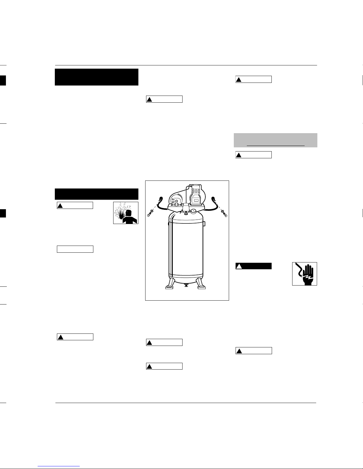
MANUAL
Figure 1
Description
General Safety
Page 2

Page 3
PIPING
Never use plastic
(PVC) pipe for
compressed air. Serious injury or death
could result.
Any tube, pipe, or hose used must have
a pressure rating higher then 150 psi.
Minimum recommended pipe size:
- up to 50 feet long use 1/2”
- greater than 50ft. long use 3/4”
Larger diameter pipe is always better.
All wiring and
electrical
connections must be performed by a
qualified electrician. Installations must
be in accordance with local and
national codes.
GROUNDING
This product must be grounded. If the
unit comes with a factory installed
cord, plug the cord into a properly
sized, grounded outlet. For units that
do not have a factory installed cord,
install permanent wiring from the
electrical source to the pressure switch
with a ground conductor connected to
the grounding screw on the pressure
switch. A properly sized cord with a
ground conductor and plug may also
be installed by the user.
Improperly grounded
motors are shock hazards.
Make sure all the
equipment is properly grounded.
WIRING
Local electrical wiring codes differ from
area to area. Source wiring, plug and
protector must be rated for at least the
amperage and voltage indicated on the
motor nameplate, and meet all electrical
codes for this minimum. Use a slow blow
fuse type T or a circuit breaker.
Overheating, short
circuiting and fire
damage will result from inadequate
wiring.
Motor protection should be used when
a motor built-in thermal overload
protection is not provided. Some 3
phase units require a magnetic starter
!
CAUTION
!
DANGER
!
WARNING
!
WARNING
(Part number MP3445 available
separately). Do not draw bolts tight.
Allow the pads to absorb vibrations. A
flexible coupling should be installed
between the tank and service piping.
This compressor is
extremely top
heavy. The unit must be bolted to the
floor with isolation pads or secured
with the wall cable (if provided)
before operating to prevent
equipment damage, injury or death.
WALL CABLE INSTALLATION
(Provided on some 30 gallon models)
Included with the safety cable are two
lag screws and washers.
1. Place an isolation pad beneath each
foot of the compressor to minimize
vibration.
2. Position the cable through the
baseplate as shown in Figure 3.
3. Place the screws through the
washers then through looped ends
of cable.
4. Secure the screws to a stud within a
framed wall. Use anchors if the wall
is concrete.
Do not secure the
compressor with
toggle bolts into drywall. Drywall
sheeting or plaster will not support
the weight of the compressor.
Never install a
shut-off valve
between the compressor pump and the
tank. Personal injury and/or equipment
damage may occur.
!
WARNING
!
WARNING
!
WARNING
Vertical Models
3
Operating Instructions
hot during use. To avoid the risk of
severe burns, never touch the
discharge tube.
Check valve - One-way valve that
allows air to enter the tank, but
prevents air in the tank from flowing
back into the compressor pump.
Belt Guard - Covers the belt, motor
pulley and flywheel.
Tank Drain Valve - This valve is
located on the bottom of the tank. Use
this valve to drain moisture from the
tank daily to reduce the risk of
corrosion.
Reduce tank pressure below 10 psi,
then drain moisture from tank daily to
avoid tank corrosion. Drain moisture
from tank(s) by opening the drain
valve located underneath the tank.
Disconnect, tag and lock
out power source, then
release all pressure from
the system before
attempting to install, service, relocate
or perform any maintenance.
LOCATION
This compressor is
not intended for
outdoor installation.
It is extremely important to install the
compressor in a clean, well ventilated
area where the surrounding air
temperature will not be more than 100°F.
Provide a minimum clearance of 18
inches between the compressor
flywheel or fan to the wall and ensure
clear access to the drain cock to
facilitate condensate drainage.
Do not locate the compressor air inlet
near steam, paint spray, sandblast areas
or any other source of contamination.
MOUNTING
Never use the
wood shipping
skids for mounting the compressor.
FLOOR MOUNTING
(All Units)
On some 30 gallon models a wall cable
is provided and should be installed. If
the unit is not secured with the wall
cable, the compressor feet MUST be
bolted to a flat, even, concrete floor or
separate concrete foundation.
Vibration isolators must be used
between the tank leg and the floor
!
CAUTION
NOTICE
!
WARNING
Figure 3 - Wall Cable Installation
Electrical Installation
HARD WIRED UNITS ONLY
Installation
Introduction
(Continued)
Page 4

Page 5
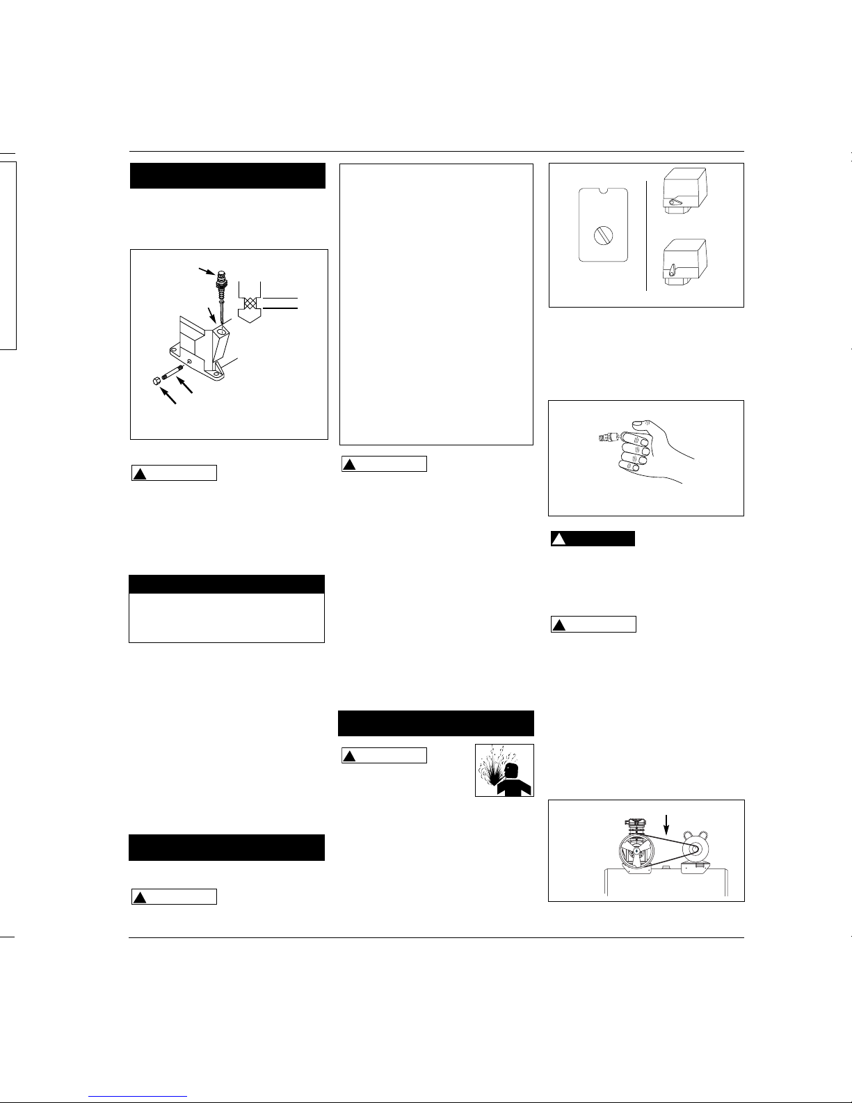
extension. Screw the cap onto one end of
the extension. Remove the oil drain plug
from the base of the pump and install the
oil drain extension (See Figure 6).
Vertical Models
5
Operating Instructions
LUBRICATION
THIS UNIT IS
SHIPPED WITHOUT
OIL! Follow lubrication instructions
before operating compressor.
Ensure oil drain extension and cap has
been installed (if included) then remove
the dipstick breather (See Fig. 6) and fill
pump oil according to the chart.
See specification label on air tank for
pump model number and refer to the
chart for the proper oil capacity. Use
SAE 30 industrial grade air compressor
oil or full synthetic motor oil like Mobil
1 10W30. Do not use regular
automotive oil such as 10W-30.
Additives in motor oil can cause valve
deposits and reduce pump life. For
maximum pump life, drain and replace
oil after the first hour of run time.
Proper oil fill level is illustrated in
Figure 6.
START-UP
Do not attach air
tools to open end
of the hose until start-up is completed
and the unit checks OK.
!
CAUTION
!
CAUTION
Never disconnect
threaded joints
with pressure in tank!
1. Remove the breather and fill pump
to the proper oil level. See
lubrication section.
2. Open the tank drain valve. Turn
outlet valve to open air flow.
3. Move pressure switch lever or knob
to the OFF position and plug in
power cord. Move pressure switch
to the AUTO position to run the
unit.
4. Run the unit for 30 minutes, under
no load, to break in pump parts.
5. Move the pressure switch lever or
knob to OFF and turn tank drain
valve to shut off air flow. The
compressor is now ready for use.
Disconnect, tag and lock
out power source, then
release all pressure from
the system before attempting to install,
service, relocate or perform any
maintenance.
All repairs should be performed by an
authorized service representative.
FOR EFFICIENT OPERATION:
Perform the following test to verify free
operation of the safety valve weekly
and follow maintenance schedule.
!
WARNING
!
WARNING
Model Approx. Oil Capacity
VS260000KB 6 oz
VT470200KB 11.5 oz
VT470000KB 12 oz
MOISTURE IN COMPRESSED AIR
Moisture in compressed air will form
into droplets as it comes from an air
compressor pump. When humidity is
high or when a compressor is in
continuous use for an extended period
of time, this moisture will collect in the
tank. When using a paint spray or
sandblast gun, this water will be carried
from the tank through the hose, and out
of the gun as droplets mixed with the
spray material.
IMPORTANT: This condensation will
cause water spots in a paint job,
especially when spraying other than
water based paints. If sandblasting, it
will cause the sand to cake and clog the
gun, rendering it ineffective.
A filter in the air line, located as near to
the gun as possible, will help eliminate
this moisture.
1. Pull ring on safety valve and allow
the ring to snap back to normal
position (See Figure 8). This valve
automatically releases air if the tank
pressure exceeds the preset
maximum.
Do not attempt to
tamper with this
valve. This valve should be checked
occasionally. If air leaks after the ring
has been released, or the valve is stuck
and cannot be actuated by the ring, the
safety valve must be replaced.
A large amount of
fast moving air will
be released if this valve is actuated
with pressure in the tank.
2. With motor OFF and unplugged,
clean debris from motor, flywheel,
tank, air lines and pump cooling fins.
DRIVE BELT
Belts will stretch in normal use. Properly
adjusted, a 5-pound force applied to
the belt between the motor pulley and
the pump will deflect the belt about
1/2”(See Figure 9).
!
CAUTION
!
DANGER
Dipstick
Breather
Full
Add
Add Oil
Oil Drain Extension
Cap
Low
Max
Figure 6
Operation
Assembly (Con’t)
Figure 8
Maintenance
A
U
T
O
/
O
F
F
Figure 7
Lever - Off
Lever - Auto
Knob
Auto/Off
1/2” Deflection
Figure 9
Page 6

Page 7

Vertical Models
7
Operating Instructions
Symptom Possible Cause(s) Corrective Action
Excessive noise
(knocking)
Continued
Large quanity of oil in the
discharge air
NOTE: In an oil
lubricated compressor there
will always be a small
amount of oil in the air
stream.
Water in discharge air/tank
Motor hums and runs slowly
or not at all
Reset mechanism cuts out
repeatedly or fuses blow
repeatedly
Tank does not hold pressure
when compressors off and
the shut off valve is closed
Pressure switch
continuously blows air out
the unloader valve
Pressure switch does not
release air when the unit
shuts off
Excessive vibration
6. Noisy check valve in
compressor system
1. Worn piston rings
2. Compressor air intake
restricted
3. Excessive oil in
compressor
4. Wrong oil viscosity
1. Normal operation. The
amount of water
increases with humid
weather
1. Use of extension cord
2. Malfunctioning check
valve or unloader valve
3. Low voltage
4. Malfunctioning pressure
switch - contacts will not
close
1. Too many devices on
same circuit
2. Incorrect fuse size or
circuit breaker
3. Malfunctioning check
valve
4. Pressure switch set too
high
5. Loose wiring
6. Malfunctioning motor
1. Worn check valve
2. Check all connections and
fittings for leaks
3. Check tank for cracks or
pin holes
1. Malfunctioning check
valve
1. Malfunctioning unloader
valve on pressure switch
1. Loose fasteners
2. Belt needs replaced
3. Belt alignment
6. Replace.
Do not disassemble check valve with
air pressure in tank
1. Replace with new rings. Maintain oil level and change oil
more frequently.
2. Clean filter. Check for other restrictions in the intake system.
3. Drain down to full level.
4. Use Mobil 1®10W-30
1. Drain tank more often. At least daily.
2. Add a filter to reduce the amount of water in the air line.
1. Do not use an extension cord. Use longer air hose with
larger diameter.
2. Replace check valve, unloader valve or pressure switch.
Do not disassemble check valve with
air pressure in tank
3. Check with voltmeter, check reset switch on motor. If reset
switch trips repeatedly, find and correct the cause. See next
item.
4. Repair or replace pressure switch.
1. Limit the circuit to the use of only the air compressor.
2. Be sure that fuses or circuit breakers are rated properly.
3. Replace check valve.
Do not disassemble check valve with
air pressure in tank
4. Adjust or replace.
5. Check all electrical connections.
6. Replace motor.
1. Replace check valve.
Do not disassemble check valve with
air pressure in tank
2. Tighten.
3. Replace tank. Never repair a damaged tank.
1. Replace the check valve if the unloader valve bleeds off
constantly.
Do not disassemble check valve with
air pressure in tank
1. Replace the pressure switch if it does not release the
pressure for a short period of time when the unit shuts off.
Do not disassemble pressure switch with
air pressure in tank
1. Tighten.
2. Replace with correct size.
3. Align flywhell and pulley.
!
DANGER
!
DANGER
!
DANGER
!
DANGER
!
DANGER
!
DANGER
Troubleshooting Chart (Continued)
Page 8

Page 9

Compresseur D’Air
Stationnaire
S’il vous plaît lire et conserver ces instructions. Lire attentivement avant de monter, installer, utiliser ou de procéder à l’entretien du produit
décrit. Se protéger ainsi que les autres en observant toutes les instructions de sécurité, sinon, il y a risque de blessure et/ou dégâts matériels!
Conserver ces instructions comme référence.
9Fr
Les modèles de compresseurs d’air sont
conçus pour fournir de l’air comprimé
aux outils pneumatiques et pour faire
fonctionner les pistolets vaporistateurs.
Les pompes fournies sont graissées à
l’huile. Un peu d’huile résiduelle est
présent dans le débit d’air comprimé.
Installer les filtres appropriés pour les
applications qui requièrent de l’air libre
d’huile ou d’eau. Le compresseur d’air
doit être monté selon les instructions,
sur un plancher solide. Autres usages
de ces modèles nieront la garantie et le
fabricant ne sera pas responsable pour
les problèmes ou dommages résultant
de l’usage incorrect.
Directives De Sécurité
Ce manuel contient de l’information
très importante qui est fournie pour la
SÉCURITÉ et pour ÉVITER LES
PROBLÈMES D’ÉQUIPEMENT.
Rechercher les symboles suivants pour
cette information.
Danger
indique
une situation hasardeuse imminente
qui RÉSULTERA en perte de vie ou
blessures graves.
Avertis-
sement
indique une situation hasardeuse
potentielle qui PEUT résulter en perte
de vie ou blessures graves.
Attention
indique
une situation hasardeuse potentielle
qui PEUT résulter en blessures.
Avis
indique
l’information importante pour éviter le
dommage de l’équipement.
Déballage
Lors du déballage, l’examiner
soigneusement pour rechercher toute
trace de dommage susceptible de s’être
produit en cours de transport. Serrer
tous raccords, boulons, etc., avant
d’utiliser le modèle.
AVIS
!
ATTENTION
!
AVERTISSEMENT
!
DANGER
Instructions D’Utilisation
Ne pas
faire
fonctionner un modèle qui a été
endommagé pendant le transport, la
manipulation ou l’utilisation. Le
dommage peut résulter en éclatement
et peut causer des blessures ou dégâts
matériels.
Puisque le compresseur d’air et les
autres pièces détachées (pompe,
pistolets, filtres, graisseurs, tuyaux, etc.)
font partie d’un système de haute
pression, il est nécessaire de suivre les
précautions suivantes.
1. Lire attentivement tous
manuels compris avec
ce produit. Bien se
familiariser avec ce
produit, ses
commandes et son utilisation.
2. Suivre tous les codes de sécurité et
d’électricité locaux ainsi qu’aux
États-Unis les National Electrical
Codes (NEC) et Occupational Safety
and Health Act (OSHA).
3. Seules les personnes bien
familiarisées avec ces règlements
!
AVERTISSEMENT
IN227705AV 12/02
© 2002 Campbell Hausfeld
Avertissement D’Air Respirable
Ce compresseur/pompe N’EST PAS
équipé pour et NE DEVRAIT PAS être
utilisé “comme soi” pour fournir de
l’air respirable. En cas
d’applications d’air pour la
consommation humaine, le
compresseur d’air/pompe doit être
équipé avec de l’équipement de
sécurité en canalisation et
d’alarme. Cet équipement
additionnel est nécessaire pour
filtrer et purifier l’air afin
d’atteindre les spécifications
minimales pour la respiration Grade
D décrites dans le Compressed Gas
Association Commodity
Specification G 7.1 - 1966, OSHA 29
CFR 1910. 134, et/ou Canadian
Standards Associations (CSA).
DÉNÉGATION DES GARANTIES
Si le compresseur est utilisé pour
les applications d’air respirable et
l’équipement de sécurité en
canalisation et d’alarme n’est pas
utilisé simultanément, les garanties
en existance seront annulées, et
Campbell Hausfeld nie toute
responsabilité pour n’importe
quelle perte, blessure ou dommage.
!
DANGER
d’utilisation doivent être autorisées
à se servir du compresseur.
4. Garder les visiteurs à l’écart de/et NE
JAMAIS permettre les enfants dans
l’endroit de travail.
5. Utiliser des lunettes de
sécurité et la
protection auditive
pendant l’utilisation du
modèle.
6. Ne pas se tenir debout sur/ni utiliser
le modèle comme une prise à main.
7. Inspecter le système d’air comprimé
et pièces détachées électriques pour
toute indication de dommage,
détérioration, faiblesse ou fuites
MANUEL
Figure 1
Description
Généralités sur la
Sécurité
Page 10

Page 11

Tous tubes, conduits, ou tuyaux utilisés
doivent avoir une classification de
pression au delà de 1034 kPa. Taille de
tuyau minimum recommandée:
- jusqu’à 15,24 m, 12,7 mm (1/2 po)
- plus que 15,24 m, 19,1 mm (3/4 po)
Un tuyau de diamètre plus large est
idéal.
Un
électricien qualifié doit effectuer
l’installation et les raccordements
électriques en respectant tous les
codes électriques locaux et nationaux.
MISE À LA TERRE
Ce produit doit être mis à la terre. Si le
modèle est livré avec un cordon installé
à l’usine, brancher le cordon dans une
prise de courant de taille correcte mise
à la terre. Pour les modèles qui n’ont
pas de cordon installé à l’usine,
installer des fils permanents de la
source d’électricité au manostat avec
un fil de terre branché à la vis de terre
sur le manostat. Vous pouvez aussi
installer un cordon de taille correcte
avec un fil de terre et une fiche.
Les moteurs qui ne sont pas
correctement mis à la terre
tiennent le risque de secousse
électrique. S’assurer que tout équipement
soit correctement mis à la terre.
INSTALLATION DE FILS
Les codes locaux concernant
!
DANGER
!
AVERTISSEMENT
MONTAGE
Ne jamais
utiliser
les palettes en bois d’expédition pour
le montage du compresseur.
MONTAGE AU PLANCHER
(Tous les modèles)
Un câble de mur est fourni et devrait
être installé pour quelques modèles de
30 gallons (114 L). Si le modèle n’est
pas fixé avec le câble de mur, les pieds
du compresseur DOIVENT être fixés à
un plancher en béton plat et égal ou
sur une fondation en béton séparée.
Les isolateurs de vibration doivent
être utilisés entre la jambe du réservoir
et le plancher (Numéro de pièce
MP3445, disponible séparément). Ne
pas trop serrer les boulons afin de
permettre que les tampons absorbent
les vibrations. Un accouplement
flexible devrait être installé entre le
réservoir et la tuyauterie de service.
Ce
compresseur est très lourd du haut. Le modèle
doit être boulonné au plancher avec
des tampons isolateurs ou fixé au
câble de mur (si fourni) avant son
utilisation pour éviter le dommage à
l’équipement, les blessures ou la mort.
MONTAGE DU CÂBLE DE MUR
(Fourni avec quelques modèles de
113,6 Litres)
Le câble de sécurité comprend deux vis
à tête carrée et rondelles.
1. Placer un tampon sous chaque pied
du compresseur pour réduire la
vibration.
2. Placer le câble à travers la plaque de
base tel qu’indiqué sur la Figure 3.
3. Placer les vis à travers les rondelles et
en suite à travers les bouts bouclés
du câble.
4. Fixer les vis à un poteau dans un mur
encadré. Utiliser des ancres sur les
murs en béton.
Ne pas
fixer le
compresseur avec des boulons à écrou
articulés dans le placoplâtre. Les murs
en placoplâtre ou en plâtre ne peuvent
pas soutenir le poids du compresseur.
Ne jamais
installer
une soupape d’arrêt entre la pompe du
compresseur et le réservoir. Blessures
et/ou dégâts matériels peuvent se
présenter.
TUYAUTERIE
Ne jamais
utiliser
les tuyaux en plastique (CPV) pour l’air
comprimé. Ceci peut causer des
blessures graves ou la mort.
!
AVERTISSEMENT
!
AVERTISSEMENT
!
AVERTISSEMENT
!
AVERTISSEMENT
!
ATTENTION
Modèles Verticaux
11 Fr
Instructions D’Utilisation
soulage les démarrages du moteur sous
charge.
Régulateur - Le régulateur contrôle la
quantité de pression d’air échappée à
la sortie de tuyau (Vendu séparément).
Soupape de Sûreté ASME - Cette
soupape laisse échapper l’air
automatiquement si la pression du
réservoir dépasse la pression maximum
réglée d’avance.
Tuyau de Décharge - Ce tuyau
transporte l’air comprimé de la pompe
au clapet. Ce tuyau devient très chaud
pendant son utilisation. Ne jamais
toucher le tuyau de décharge afin
d’éviter des brûlures sévères.
Clapet - Une soupape à sens unique qui
permet à l’air d’entrer le réservoir mais
qui empêche que l’air du réservoir
retourne dans la pompe du compresseur.
Carter de Courroie - Couvre la
courroie, la poulie de moteur et le
volant.
Robinet de Purge de Réservoir Cette soupape est située au fond du
réservoir. Utiliser cette soupape pour
purger l’humidité du réservoir
quotidiennement afin de réduire le
risque de corrosion.
Réduire la pression du réservoir sous
68,95 kPa, et ensuite purger l’humidité
du réservoir quotidiennement afin
d’éviter la corrosion. Purger l’humidité
du(des) réservoir(s) en ouvrant le robinet
de purge situé sous le réservoir.
Débrancher, étiquetter et
verrouiller la source de
puissance, ensuite dissiper toute la
pression du système avant d’installer,
réparer, déplacer ou de procéder à
l’entretien du modèle.
ENDROIT
Ce
compresseur n’est pas conçu pour l’utilisation à
l’extérieur.
Il est très important d’installer le
compresseur dans un endroit propre et
bien aéré, où la température de l’air ne
dépassera pas 38,1˚ C.
Une distance minimum de 45,7 cm est
requise entre le volant du compresseur
ou un évantail et un mur afin d’assurer
l’accès au robinet de purge.
Ne pas situer l’arrivée d’air du
compresseur près de la vapeur, peinture
pulvérisée, endroits de décapage au
sable et autres sources de contamination.
AVIS
!
AVERTISSEMENT
Introduction (Suite)
Figure 3 - Installation du Câble de Mur
Installation Électrique
INSTALLATION DE FILS DIRECTE
SEULEMENT
Installation
Page 12

Page 13

terre de la fiche et au corps métallique
du manostat.
QUINCAILLERIE ADDITIONNELLE
EXIGÉE
Acheter des tuyaux, un régulateur et
une soupape d’arrêt ayant une
classification minimum de 1034 kPa et
qui dépasse la pression de service
maximum du compresseur.
RALLONGE DE VIDANGE D’HUILE
Un rallonge de vidange d’huile et un
bouchon sont compris avec quelques
modèles (situés avec le manuel
d’utilisation). Installer le rallonge de
vidange d’huile et le bouchon avant
d’ajouter l’huile à la pompe. Utiliser
du ruban Teflon
®
ou du mastique sur
les filets à chaque bout du rallonge de
vidange d’huile pour éviter les fuites.
Visser le bouchon sur un bout du
rallonge. Enlever le bouchon de
vidange d’huile de la base de la pompe
et installer le rallonge de vidange
d’huile (Voir Figure 6).
GRAISSAGE
CE
MODÈLE
EST EXPÉDIÉ SANS HUILE! Suivre les
instructions de graissage avant
d’utiliser le compresseur.
S’assurer que le rallonge de vidange
d’huile et le bouchon soient installés (si
compris). Enlever le reniflard de la
réglette-jauge (Voir Fig. 6) et remplir la
pompe d’huile selon le tableau.
Se référer à la décalcomanie de
spécifications sur le réservoir pour le
numéro de la pompe et se référer au
tableau pour la capacité d’huile correcte.
Utiliser l’huile pour compresseur d’air
industrielle SAE 30 ou l’huile
complètement synthétique pour moteurs
!
ATTENTION
Modèles Verticaux
13 Fr
Instructions D’Utilisation
telle que Mobil 1 10W-30. Ne pas
utiliser l’huile pour automobile
ordinaire
telle que 10W-30. Les additifs
dans l’huile de moteur peuvent causer de
l’encrassement dans les soupapes et
peuvent diminuer la vie de la pompe.
Pour assurer la durée maximum de la
pompe, purger et remplacer l’huile après
la première heure de fonctionnement. Le
niveau d’huile correct est illustré sur la
Figure 6.
DÉMARRAGE
Ne pas
brancher
les outils pneumatiques au bout ouvert
du tuyau avant que le démarrage soit
complet et que le modèle fonctionne
correctement.
Ne jamais
débrancher les raccords filetés si le réservoir
est pressurisé!
1. Enlever le reniflard et remplir la
pompe d’huile jusqu’au niveau correct.
Se référer à la section de graissage.
2. Ouvrir le robinet de purge de
réservoir. Tourner la soupape de
sortie afin d’ouvrir la circulation d’air.
3. Mettre le levier ou le bouton du
manostat à la position OFF et brancher
!
AVERTISSEMENT
!
ATTENTION
le cordon d’alimentation. Mettre le
levier du manostat à la position AUTO
pour faire fonctionner le modèle.
4. Faire fonctionner le modèle pour 30
minutes, sans charge afin d’effectuer
le rôdage des pièces de la pompe.
5. Mettre le levier ou bouton du
manostat à la position OFF et
tourner le robinet de purge de
réservoir afin de couper la circulation
d’air. Le compresseur est prêt à
utiliser.
Débrancher, étiquetter et
verrouiller la source de
puissance et dissiper la
pression du système avant de monter,
réparer, déplacer ou de procéder à
l’entretien du modèle.
Toutes réparations doivent être
performées par un représentant de
service authorisé.
POUR LE FONCTIONNEMENT
EFFICACE:
Faire l’essaie de la soupape de sûreté
chaque semaine pour s’assurer qu’elle
fonctionne librement et respecter
l’horaire d’entretien.
1.Tirer sur l’anneau
de la soupape de
sûreté et la laisser
revenir à sa
position normale
(Voir Figure 8). Cette soupape
relâche l’air automatiquement
lorsque la pression du réservoir
dépasse le maximum réglé d’avance.
Ne pas
trifouiller
avec cette soupape. Vérifier cette
soupape de temps en temps. S’il y a
des fuites d’air après que l’anneau soir
relâché, ou si la soupape est prise et ne
peut pas être actionnée par l’anneau, la
soupape de sûreté doit être remplacée.
Une
large
!
ATTENTION
!
DANGER
!
AVERTISSEMENT
Dipstick
Breather
Full
Add
Add Oil
Oil Drain Extension
Cap
Low
Max
Figure 6
Fonctionnement
Reniflard de la
reglette-jauge
Ajoutez l’huile
Plein
Ajoutez
Rallonge de vidange d’huile
Bouchon
Bas
VS260000KB 0,18 L
VT470200KB 0,34 L
VT470000KB 0,35 L
Modèle Capacité d’huile approx.
HUMIDITÉ DANS L’AIR COMPRIMÉ
L’humidité dans l’air comprimé forme des
gouttelettes en arrivant de la pompe du
compresseur d’air. Si l’humidité est
élevée, ou si le compresseur est utilisé
continuellement, cette humidité
s’accumulera dans le réservoir. Pendant
l’utilisation d’un pistolet à peinture ou
d’un pistolet pour le décapage au sable,
cette eau sera transportée du réservoir par
moyen du tuyau, et en forme de
gouttelettes, mélangée avec le matériel
utilisé.
IMPORTANT: Cette condensation peut
causer des taches d’eau sur votre travail de
peinture, surtout pendant la pulvérisation
de peinture qui n’est pas à base d’eau.
Pendant le décapage au sable, cette eau
servira à tenir le sable ensemble et causera
une obstruction dans le pistolet.
Un filtre à air en canalisation situé aussi
près du pistolet que possible aidera à
éliminer cette humidité.
Montage
Installation (Suite)
A
U
T
O
/
O
F
F
Figure 7
Levier - Off
Levier - Auto
Bouton
Auto/Off
Entretien
Figure 8
Page 14

Page 15

Modèles Verticaux
15 Fr
Instructions D’Utilisation
Symptôme Cause(s) Possible(s) Mesure Corrective
Bruit excessif
(cognement)
Suite
Large quantité d’huile dans
l’air de décharge
REMARQUE: Il y aura
toujours un peu d’huile dans
le jet d’air avec un
compresseur graissé par
l’huile.
Eau dans l’air de
débit/réservoir
Le moteur ronronne et
fonctionne lentement ou
pas du tout
Le mécanisme de
réenclenchement se
déclenche à maintes reprises
ou les fusibles sautent à
maintes reprises
Le réservoir ne conserve pas
la pression quand le
compresseur est hors circuit
et la soupape d’arrêt est
fermée
Le manostat laisse souffler
de l’air continuellement à
travers de la soupape de
déchargement
Le manostat ne relâche pas
l’air lorsque le modèle se
coupe (off)
Vibration excessive
6. Clapet bruyant dans le système de
compresseur
1. Segments de piston usés
2. Arrivée d’air du compresseur
limité
3. Huile excessive dans le
compresseur
4. Viscosité d’huile incorrecte
1. Fonctionnement normal. La
quantité d’eau augmente avec le
temps humide
1. Cordon prolongateur utilisé
2. Fonctionnement défectueux du
clapet ou de la soupape de
déchargement
3. Basse tension
4. Panne de manostat - contacts ne
ferment pas
1. Trop d’appareils sur le même
circuit
2. Taille de fusible ou de disjoncteur
incorrecte
3. Fonctionnement défectueux du
clapet
4. Manostat réglé trop haut
5. Fils désserrés
6. Fonctionnement défectueux du
moteur
1. Clapet usé
2. Inspecter tous branchements et
raccordements pour des fuites
3. Inspecter le réservoir pour des
fentes ou des trous d’épingles
1. Fonctionnement défectueux du
clapet
1. Fonctionnement défectueux de la
soupape de déchargement sur le
manostat
1. Attaches désserrés
2. Changement de la courroie exigé
3. Redressage de la courroie
la partie supérieure du piston. Remplacer la culasse et la plaque de
soupape et utiliser un nouveau joint d’étanchéité. Voir la section de
Graissage pour l’huile recommandée.
6. Remplacer.
Ne pas démonter le clapet
si le réservoir est pressurisé
1. Remplacer les segments de piston. Entretenir le niveau d’huile
correct et changer l’huile plus souvent.
2. Nettoyer le filtre. Vérifier le système d’arrivée pour autres
restrictions.
3. Vidanger jusqu’au niveau plein.
4. Utiliser l’huile Mobil 1
®
10W-30
1. Purger le réservoir plus souvent, au moins quotidiennement.
2. Ajouter un filtre pour diminuer la quantité d’eau dans la
canalisation d’air.
1. N’utilisez pas un cordon prolongateur. Utilisez un tuyau d’air plus
long avec un diamètre plus large.
2. Remplacer le clapet, la soupape de déchargement ou le manostat.
Ne pas démonter le clapet
si le réservoir est pressurisé
3. Vérifier avec un voltmètre, inspecter le disjoncteur de
réenclenchement du moteur. Si le disjoncteur de réenclenchement
se déclenche à maintes reprises, rechercher et corriger la cause. Voir
l’article suivant.
4. Réparer ou remplacer le manostat.
1. Limiter l’usage du circuit au compresseur d’air seulement.
2. Vérifier la classification des fusibles et des disjoncteurs.
3. Remplacer le clapet.
Ne pas démonter le clapet
si le réservoir est pressurisé
4. Régler ou remplacer.
5. Inspecter tous les branchements électriques.
6. Remplacer le moteur.
1. Remplacer le clapet.
Ne pas démonter le clapet
si le réservoir est pressurisé
2. Serrer.
3. Remplacer le réservoir. Ne jamais réparer un réservoir endommagé.
1. Remplacer le clapet si la soupape de déchargement a une fuite d’air
continue.
Ne pas démonter le clapet
si le réservoir est pressurisé
1. Remplacer le manostat si la pression n’est pas dissipé pendant une
courte durée quand le modèle se coupe.
Ne pas démonter le
manostat si le réservoir est
pressurisé
1. Serrer.
2. Remplacer avec une courroie de taille correcte.
3. Aligner le volant et la poulie.
!
DANGER
!
DANGER
!
DANGER
!
DANGER
!
DANGER
!
DANGER
Guide De Dépannage (Suite)
Page 16

Page 17

Compresores de
Aire Estacionarios
Sírvase leer y guardar estas instrucciones. Lea con cuidado antes de tratar de armar, instalar, manejar o darle servicio al producto descrito en
este manual. Protéjase Ud. y a los demás observando todas las reglas de seguridad. El no seguir las instrucciones podría resultar en heridas y/o
daños a su propiedad. Guarde este manual como referencia.
17 Sp
Estos compresores de aire están
diseñados para suministrarle aire
comprimido a herramientas neumáticas
y operar pistolas pulverizadoras. Los
cabezales suministrados con estas
unidades están lubricados con aceite. El
aire comprimido suministrado contiene
residuos de aceite. Para utilizarlo en
aplicaciones que requieran el
suministro de aire sin residuos de aceite
o agua, le debe instalar un filtro
adecuado. El compresor de aire se debe
colocar sobre un piso sólido según las
instrucciones suministradas. Cualquier
otro uso de estas unidades cancelaría la
garantía y el fabricante no sería
responsable por los problemas o daños
ocasionados por dichos usos.
Medidas De Seguridad
Este manual contiene información que
es muy importante que sepa y
comprenda. Esta información se la
suministramos como medida de
SEGURIDAD y para EVITAR
PROBLEMAS CON EL EQUIPO. Debe
reconocer los siguientes símbolos.
Ésto le
indica que
hay una situación inmediata que LE
OCASIONARIA la muerte o heridas de
gravedad.
Ésto le
indica
que hay una situación que PODRIA
ocasionarle la muerte o heridas de
gravedad.
Ésto le
indica
que hay una situación que PODRIA
ocasionarle heridas no muy graves.
Ésto le
indica
una información importante, que de no
seguirla, le podría ocasionar daños al
equipo.
AVISO
!
PRECAUCION
!
ADVERTENCIA
!
PELIGRO
Manual de Instrucciones
Para desempacar
Al desempacar este producto, revíselo
con cuidado para cerciorarse de que
esté en perfecto estado. Igualmente,
cerciórese de apretar todos los pernos,
tuercas y conexiones, antes de usarlo.
No debe
utilizar la
unidad si se ha dañado durante el
envío, manejo o uso. Los daños podrían
ocasionar una explosión y ocasionarle
heridas o daños a su propiedad.
Como el compresor de aire y otros
componentes usados (bomba de
material, pistolas pulverizadoras,
filtros, lubricadores, mangueras, etc.)
intengran un sistema de alta presión,
en todo momento deberá seguir las
siguientes medidas de seguridad:
1. Lea con cuidado todos
los manuales incluídos
con este producto.
Familiarícese con los
controles y el uso
adecuado del equipo.
!
ADVERTENCIA
IN227705AV 12/02
© 2002 Campbell Hausfeld
Advertencia sobre
el aire respirable
Este compresor/cabezal no viene listo
de fábrica para suministrarle aire
respirable. Antes de utilizarlos con
este fin, deberá instalarle un sistema
de seguridad y alarma incorporado a
la línea. Este sistema adicional es
necesario para filtrar y purificar el
aire adecuadamente, para cumplir con
las especificaciones mínimas sobre
aire respirable de Grado D descritas
en la Especificación de Productos G
7.1 - 1966 de la Asociación de Aire
Comprimido.Igualmente, deberá
cumplir los requisitos establecidos
por el Artículo 29 CFR 1910. 134 de la
Organización norteamericana OSHA
y/o la Canadian Standards
Associations (CSA).
RENUNCIA A LAS GARANTIAS
Si el compresor se utiliza para producir
aire respirable SIN haberle instalado el
sistema de seguridad y alarma, todas
la garantías se anularán y la compañia
Campbell Hausfeld. no asumirá
NINGUNA responsabilidad por
pérdidas, heridas personales o daños.
!
PELIGRO
2. Siga todos los códigos de seguridad
laboral y electricidad establecidos
en su país, por ejemplo, los de la
NEC y OSHA en EUA.
3. Sólo personas bien familiarizadas
con estas medidas de seguridad
deben utilizar el compresor.
4. Mantenga a los visitantes alejados y
NUNCA permita la presencia de
niños en el área de trabajo.
5. Use anteojos de
seguridad y protéjase
los oídos para operar la
unidad.
6. No se encarame sobre la unidad ni
la use para sostenerse.
7. Antes de cada uso, revise el sistema
de aire comprimido y los
MANUAL
Figura 1
Descripción
Generales Seguridad
Page 18

Page 19

No use
tornillos
de fiador para fijar el compresor a
muros en seco. Éstos no son lo
suficientemente resistentes para
sostener el peso del compresor.
Nunca
instale la
válvula de cierre entre el cabezal y el
tanque. Ésto podría ocasionarle
heridas y/o daños a su propiedad.
TUBERIAS
Nunca
use
tuberías de plástico (PVC) en sistemas
de aire comprimido. El hacerlo podría
ocasionarle heridas o daños a su
propiedad.
Todo tubo o manguera empleado debe
estar capacitado para presiones de más
de 150 psi. Tamaño mínimo
recomandado para tubos:
- hasta 50 pies de largo: use 1/2”
- más de 50 pies: use 3/4”
Es siempre aconsejable usar diámetros
mayores.
Todos
los
trabajos de alambrado y conexiones
eléctricas las debe hacer un electricista
calificado. Las instalaciones eléctricas
se deben hacer según los códigos
locales y nacionales.
CONEXION A TIERRA
Este aparto debe estar conectado a
tierra. Si la unidad trae un cordón
instalado de fábrica, enchúfelo en una
toma de tamaño apropiado y conectada
a tierra. Para las unidades que no traen
cordón instalado de fábrica, instale un
alabrado permanenete desde la fuente
de energía hasta el presostato, con un
cable de tierra conectado al tornillo de
tierra del presostato. El usuario puede
también instalar un cordón de tamaño
apropiado con enchufe y cable de tierra.
Los artefactos eléctricos
conectados a tierra
incorrectamente constituyen
un riesgo de electrocutamiento.
Cerciórese de que todas las conexiones
a tierra estén hechas adecuadamente.
ALAMBRADO
Los códigos locales de eléctricidad
varian de un área a otra. El sistema de
alambrado, los enchufes y protectores
deben cumplir con el voltaje y amperaje
indicado en la placa del motor.
Igualmente, éstos deben cumplir con los
códigos locales de eléctricidad. Use un
fusible tipo T de acción retardada.
!
PELIGRO
!
ADVERTENCIA
!
ADVERTENCIA
!
ADVERTENCIA
!
ADVERTENCIA
En algunos modelos de 30 galones se
proporciona un cable de pared el cual
debe ser instalado. Si la unidad no se
asegura a la pared con un cable,
DEBERA atornillar las patas a una
superficie plana y nivelada, tal como un
piso de concreto o una base de concreto
aparte. Debe usar almohadillas
aislantes entre las patas del tanque y el
piso. No apriete los pernos
excesivamente. (Parte núm. MP3445,
disponible por separado). Permita que
las almohadillas absorban la vibración.
Deberá instalar conexiones flexibles
entre el tanque y las tuberías.
La parte
superior
de este compresor es sumamente
pesada. La unidad se atornillar al piso
y colocarle almohadillas aislantes o se
debe asegurar a la pared con el cable
(si se incluye) antes de utilizarla para
evitar daños, heridas o la muerte.
INSTALACION DEL CABLE PARA
SOSTENERLO A LA PARED
(Suministrado con algunos modelos de
113,6 Litros)
Con el cable de seguridad se incluyen
dos tornillos de fiador y arandelas.
1. Coloque una almohadilla aislante
debajo de cada pata del compresor
para minimizar la vibración.
2. Coloque el cable en la base tal como
se le indica en la Figura 3.
3. Colóquele las arandelas a los
tornillos e introdúzcalos en los aros
de los extremos del cable.
4. Si es una pared de entramado, los
tornillos se deben fijar al montante.
Use una trabilla si la pared es de
concreto.
!
ADVERTENCIA
Modelos Verticales
19 Sp
Manual de Instrucciones
Válvula de Seguridad ASME - Esta
válvula libera el aire automáticamente
si la presión del tanque excede el nivel
máximo fijado.
Tubo de Descarga - Este tubo
transporta el aire comprimido del
cabezal a la válvula de chequeo. Este
tubo se calienta mucho durante el uso.
Para evitar el riesgo de sufrir
quemaduras severas, nunca toque el
tubo de descarga.
Válvula de Chequeo - Esta válvula de
un solo sentido permite la entrada de
aire al tanque, pero evita que se
regrese al cabezal.
Tapa de las Bandas - Cubre la banda,
la polea del motor y el volante.
Válvula de drenaje del tanque - Esta
válvula está ubicada en la parte inferior
del tanque. Úsela para drenar la
humedad del tanque diariamente para
reducir el riesgo de que el tanque se
oxide.
Reduzca la presión del tanque a menos
de 0,69 bar, después drene la humedad
del tanque para eviotar que se oxide.
Drene la humedad del/de los tanque(s)
abriendo la válvula de drenaje ubicada
debajo del tanque.
Desconecte el cordón
eléctrico y amárrelo y
después libere toda la presión del
sistema antes de tratar de instalarlo,
darle servicio o darle cualquier tipo de
mantenimiento.
UBICACION
Este
compresor no está diseñado para instalarse a
la intemperie.
Es sumamente importante que instale el
compresor en un área limpia y bien
ventilada donde la temperatura
ambiental no exceda los 38,1˚ C.
La distancia mínima entre el volante del
compresor o ventilador y la pared debe
ser de 45,7 cm (18”) para tener acceso a
la llave de drenaje sin incovenientes.
No coloque la entrada de aire del
compresor en un área donde haya vapor,
se rocíe pintura o arena o haya ningún
otro tipo de contaminación.
INSTALACION
Nunca
instale el
compresor sobre las bases de madera
usadas para transportarlo.
INSTALACION EN EL PISO
(Todas las Unidades)
!
PRECAUCION
AVISO
!
ADVERTENCIA
Figura 3 - Instalación del cable para
sostenerlo a la pared
Instalaciones Eléctricas
SOLO LAS UNIDADES CON
CONEXIONES PERMANENTES
Instalación
Introducción (Con’t)
Page 20

Page 21

ACCESORIOS ADICIONALES
NECESARIOS
Compre una manguera, un regulador y
una válvula de cierre diseñados para
presiones mínimas de 10,3 bar y que
excedan las presiones máximas de
trabajo del compresor.
EXTENSION PARA DRENAR EL
ACEITE
Algunos modelos traen una extensión
para el sistema de drenaje de aceite y
una tapa (anexos al manual de
instrucciones). Instale la extensión y la
tapa antes de añadirle aceite al
cabezal. Para evitar fugas de aceite,es
muy recomendable que le aplique cinta
pegante de Teflón
®
o un sello en pasta a
las roscas en cada uno de los extremos
de la extensión. Atornille la tapa en uno
de los extremos de la extensión, quítele
el tapón a la base del cabezal e instálele
la extensión (Vea la Figura 6).
LUBRICACION
ESTA
UNIDAD
VIENE DE FABRICA SIN ACEITE. Siga las
instrucciones de lubricación antes de
utilizar el compresor.
Cerciórese de haberle instalado la
extensión para drenar el aceite y la tapa
(si se incluyen), sáquele la varilla al
respiradero (Vea la Fig. 6) y llénelo de
aceite según se le indica en la tabla.
La etiqueta en el tanque de aire
especifica el modelo del cabezal y la
tabla en este manual le indica la
capacidad de aceite para cada modelo.
Use aceite SAE 30 de calidad industrial
para compresores de aire o un sintético
!
PRECAUCION
Modelos Verticales
21 Sp
Manual de Instrucciones
tipo Mobil 1 10W30. No use aceite
normal para vehículos tipo 10W-30.
Los aditivos en los aceites para motores
pueden ocasionar depósitos de residuos
en las válvulas y reducir la duración del
cabezal. Para lograr la máxima
duración del cabezal, drene el aceite y
cámbielo después de la primera hora de
funcionamiento. La Figura 6 le indica el
nivel adecuado de aceite.
PREPARACION PARA EL USO
No co-
necte las
herramientas neumáticas al extremo de
la manguera hasta terminar el proceso
de preparación para el uso y se haya
cerciorado de que la unidad está lista
para funcionar.
¡Nunca
desconecte las conexiones con roscas antes
de liberar la presión del tanque!
1. Sáquele el respiradero y llene el
cabezal de aceite hasta alcanzar el
nivel adecuado. Vea la sección de
lubricación.
2. Abra la válvula de drenaje del
tanque. Abra la llave de salida para
permitir el flujo de aire.
3. Mueva la palanca o perilla del
presostato a la posición OFF y
enchufe el cordón de alimentación.
Coloque la palanca del presostato en
AUTO para encender la unidad.
4. Deje que la unidad funcione por 30
minutos, sin carga, para que las
piezas del cabezal se fijen.
5. Mueva la palanca o perilla del
presostato a la posición OFF y gire la
válvula de drenaje del tanque para
!
ADVERTENCIA
!
PRECAUCION
HUMEDAD EN EL AIRE COMPRIMIDO
La humedad que se acumula en el aire
comprimido se convierte en gotas a
mediada que sale del cabezal. Cuando el
nivel de humedad es muy alto o cuando
el compresor ha estado en uso
continuop por mucho tiempo, esta
humedad se acumulará en el tanque.
Cuando esté pintando o rociando arena,
la humedad saldrá del tanque mezclada
con el material que esté rociando.
IMPORTANTE: Esta condensación
ocasionará manchas en la pintura,
especialmente cuando esté pintando con
pinturas que no sean a base de agua. Si
está rociando arena, la humedad hará
que la arena se aglutine y obstruya la
pistola.
Instale un filtro de línea, ubicado lo más
cerca posible de la pistola, para tratar de
eliminar este problema.
cortar el flujo de aire. El compresor
estará listo para funcionar.
Desconecte el cordón
eléctrico y amárrelo y
después libere toda la
presión del sistema antes de tratar de
instalarlo, darle servicio o darle
cualquier tipo de mantenimiento.
Todos los trabajos de reparación los
debe hacer un técnico autorizado.
PARA EL FUNCIONAMIENTO
EFICIENTE:
Semanalmente haga la siguiente prueba
para verificar el funcionamiento
adecuado de la válvula de seguridad y
déle el mantenimiento necesario
indicado en la tabla de mantenimiento.
1. Hále el anillo de
la válvula de
seguridad y
déjelo que
regrese a su
posición normal
(Vea la Figura 8). Esta válvula libera el
aire automáticamente si la presión del
tanque excede el nivel máximo fijado.
Nunca
trate de
modificar esta válvula. Esta válvula se
debe chequear ocasionalmente. Si hay
fugas de aire después de soltar el
anillo, o si la válvula está atascada y no
la puede activar con el anillo, deberá
reemplazarla.
Si la
válvula de
seguridad se hace funcionar con presión
de aire en el tanque, se liberará una gran
cantidad de aire que se encuentra en
movimiento a gran velocidad.
2. Con el motor APAGADO y
desconectado, limpie el motor, el
volante, el tanque, las líneas de aire y
las aletas de enfriamiento del cabezal.
BANDAS
Las bandas se estiran con el uso normal.
Cuano están bien ajustadas la deflexión
!
PRECAUCION
!
PELIGRO
!
ADVERTENCIA
Ensamblaje
Dipstick
Breather
Full
Add
Add Oil
Oil Drain Extension
Cap
Low
Max
Extensión del sistema
de drenaje de aceite
Tapa
Para añadirle
el aceite
Varilla del
respiradero
Lleno
Añádale
aceite
Figura 6
Modelo Cap. Aprox. de Aceite
VS260000KB 0,18 L
VT470200KB 0,34 L
VT470000KB 0,35 L
Funcionamiento
Bajo
A
U
T
O
/
O
F
F
Figure 7
Palanca - Apagado
Palanca -
Automático
Perilla Auto/
Apagado
Mantenimiento
Figura 8
Page 22

Page 23

Modelos Verticales
23 Sp
Manual de Instrucciones
Problema Posible(s) Causa(s) Acción a Tomar
Aceite excesivo en el aire
de descarga. NOTA: En un
compresor lubricado con
aceite siempre hay una
pequeña cantidad de aceite
en el flujo de aire.
Agua en el aire de salida o
en el tanque
El motor zumba y funciona
lentamente o no funciona
en lo absoluto
El mecanismo de reajuste
interrumpe el
funcionamiento
constantemente o los
fusibles se funden con
frecuencia
El tanque no mantiene la
presión cuando el
compresor está apagado y
la válvula de cierre está
cerrada
El interruptor de presión
tira continuamente aire por
la válvula de descarga
El interruptor de presión no
libera el aire cuando la
unidad de apaga
Vibración excesiva
1. Aros del émbolo desgastados
2. La entrada de aire del compresor
está restringida
3. Demasiado aceite en el compresor
4. Viscosidad del aceite equivocada
1. Operación normal. La cantidad
de agua aumenta con el clima
húmedo
1. Utiliza un cordón de extensión
2. Malfuncionamiento de la válvula
de verificación o de la válvula de
descarga
3. Voltaje bajo
4. Malfuncionamiento del
interruptor presión, los contactos
no se cierran
1. Demasiados aparatos en el mismo
circuito
2. Tamaño incorrecto del fusible o
del disyuntor
3. Malfuncionamiento de la válvula
de verificación
4. Interruptor de presión fijado
demasiado alto
5. Cableado flojo
6. Malfuncionamiento del motor
1. Válvula desgastada
2. Verifique todas las conexiones y
los accesorios para detectar fugas
3. Revise el tanque para detectar
fisuras o perforaciones
1. Malfuncionamiento de la
válvula
1. Malfuncionamiento de la válvula
de descarga en el interruptor de
presión
1. Ajustadores flojos
2. La correa necesita ser reemplazada
3. Alineación de la correa
1. Reemplácelos con aros nuevos. Mantenga el nivel de aceite y
cambie el aceite con más frecuencia.
2. Limpie el filtro. Verifique otras restricciones en el sistema de entrada.
3. Escúrralo hasta que alcance el nivel de lleno.
4. Use Mobil 1® 10W-30.
1. Drene el tanque con más frecuencia. Al menos diariamente.
2. Agregue un filtro
1. No utilice un cordón de extensión. Utilice una manguera de aire
más larga con un diámetro mayor.
2. Reemplace la válvula de verificación, la válvula de descarga o el
interruptor de presión.
No desarme la válvula con
presión de aire en el tanque.
3. Verifique con un voltímetro, revise el interruptor de reajuste del
motor. Si este se dispara varias veces, busque la causa y corríjala.
Consulte el siguiente punto.
4. Repare o reemplace el interruptor de presión.
1. Use sólo el compresor de aire en el circuito.
2. Asegúrese de que los fusibles o los disyuntores sean del tamaño
adecuado.
3. Reemplace la válvula de verificación
No desarme la válvula con
presión de aire en el tanque.
4. Ajuste o reemplace el interruptor.
5. Verifique todas las conexiones eléctricas
6. Reemplace el motor.
1. Reemplace la válvula.
No desarme la válvula con
presión de aire en el tanque
.
2. Apriete.
3. Reemplace el tanque. Nunca repare un tanque dañado
1. Reemplace la válvula de verificación si la válvula de descarga tiene
perdidas constantemente.
No desarme la válvula con
presión de aire en el tanque.
1. Reemplace el interruptor de presión si éste no libera la presión por
un breve período de tiempo cuando se apaga la unidad.
No desarme el interruptor de
presión si hay presión en el
tanque.
1. Ajústelos.
2. Reemplace la correa con otra del tamaño adecuado.
3. Alinee el volante y la polea.
!
PELIGRO
!
PELIGRO
!
PELIGRO
!
PELIGRO
!
PELIGRO
Guía de Diagnóstico de Averías (Continuación)
Page 24

 Loading...