

Campbell Hausfeld LIGHT DUTY CART Airless Paint Sprayers, PS###A, PS###B, PS###C, PS###D Assembly Instructions And Parts List
...Page 1
Airless Paint
Sprayers
Please read and save these instructions. Read carefully before attempting to assemble, install, operate or maintain the product described.
Protect yourself and others by observing all safety information. Failure to comply with instructions could result in personal injury and/or property damage! Retain instructions for future reference.
Assembly Instructions and Parts List
Airless Paint Sprayers
IN421000AV 3/02
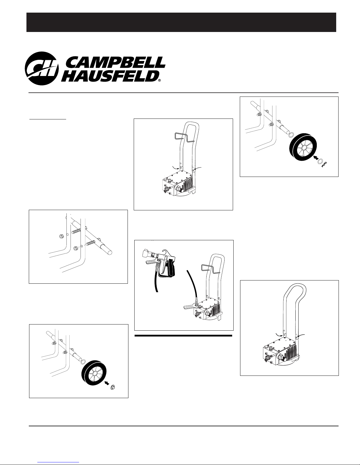
Assembly Instructions
LIGHT DUTY CART MODELS
Tools required:
7/16” Wrench or
adjustable
11/16” Wrench or
adjustable
Hammer
1. Open packaging and check contents
against packing list on hardware pack.
2. Stand pump upright and hold steady.
Attach axle to cart legs by inserting
pre-assembled bolts into holes in cart
legs. Secure with one 1/4” - 20 nut on
each bolt. Use 7/16” wrench to tighten (See Figure 1).
3. Slide one 5/8” I.D. washer and wheel
on to each end of the axle. Using a
hammer, tap a pal nut onto each end
of the axle to retain the wheels (See
Figure 2).
4. Slide handle on to cart by depressing
the retaining snaps while pushing
handle in place. Be sure to check that
the retaining snaps lock into holes in
handle. Hose rack should be facing
the pump (See Figure 3).
5. Attach high pressure hose to pump
and spray gun using a 11/16” wrench
(See Figure 4). Do not attach suction
assembly at this time.
Assembly Instructions
HEAVY DUTY CART MODELS
1. Place washer from parts pack onto
axle.
2. Place wheel onto axle with side with
the longest hub going on first.
3. Place another washer on the axle.
4. Place cotter pin through hole in the
end of the axle.
5. Repeat for the other side (See
Figure 5).
6. Slide the two ends of the handle
over the two ends of the bottom
frame. The bend in the handle
should be away from the unit.
7. Stand behind the unit and reach
over the handle to grip the ends at
the bottom of the handle. Using
your thumb and forefinger, depress
the Valco Snaps and gently push
down on the handle until it starts
over the snaps. Then move your
hands to the top of the handle and
push it the rest of the way down
(See Figure 6).
8. When the handle is all the way
down the snaps will “click” into
place. If all four snaps do not pop
through, grasp the handle and twist
it right to left until the remaining
snap pops through.
Figure 1 - Attach Axle
Figure 2 - Attach Wheels
Figure 3 - Attach Handle
Figure 5 - Attach Wheels
Figure 4 - Attach Hose
Figure 6 - Attach Handle
Push
Lock
Push
Lock
For parts, product & service information
visit www.chpower.com
© 2002 Campbell Hausfeld/Scott Fetzer
BUILT TO LAST
D
L
E
L
L
E
B
P
F
S
U
A
H
M
A
C
Page 2

2
Assembly Instructions and Parts List
Assembly (Continued)
9. Place bucket hook over top of frame
with the hook to the outside of the
frame.
10. Line up the two holes in the bucket
hook with the two holes in the top
of the frame (See Figure 7).
If using a power
tool to drive the
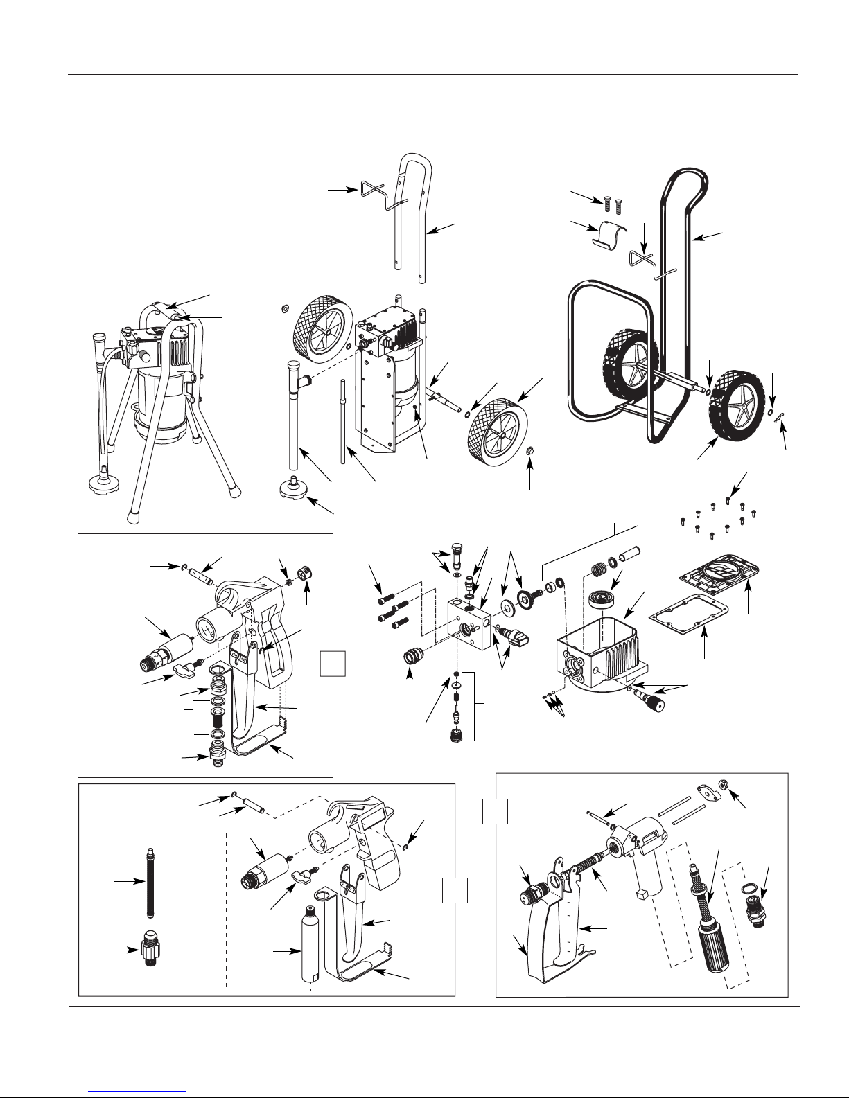
1 Stand handle AL172304AV 1
2 Handle bolt AL152201AV 2
3 Hose rack AL066101AV 1
4 Handle (Includes hose rack) AL066021SV 1
5 Axle (Includes bolts) AL066030SV 1
6 Washer ST090200AV 2
7 Wheel WA002601AV 2
8 Pal nut AL066300AV 2
9 Nut AL060000AV 2
10 By-Pass tube and clamp AL174302SV 1
11 Suction tube assembly AL138404SV 1
(Includes tube and connectors)
12 Suction bell assy. (Includes filter) AL111000SV 1
13 Bucket hook AL136200AD 1
14 Screws HP007117AV 4
15 Handle (Includes hose rack) AL139200SV 1
16 Washer AL136000AV 4
17 Cotter pin AL149700AV 2
18 Wheel WA002602AV 2
19 Faceplate screws HP007118AV 1
20 Piston kit AL131502SV 1
21 Diaphragm kit (Check valve
kit included) See chart 1
22 Hose adapter (Includes washer) AL104700SV 1
23 Outlet valve assembly AL129600SV 1
24 Pump block (Incl. all washers) AL042413SV 1
25 Inlet valve assembly AL165400SV 1
26 Pushbutton seal AL162000AV 1
27 Outlet push/pull assy. AL159500SV 1
28 Prime/Spray valve assembly AL132100SV 1
29 Check valve kit AL163200SV 1
30 Pressure valve assembly AL131401SV 1
31 Housing kit
(Includes 20,29, & 30) See chart 1
32 Eccentric and bearing kit See chart 1
33 Faceplate gasket AL013702AV 1
34 Cast faceplate AL045102AV 1
35 Valve stem nut (3 pack) AL083300AV 1
36 Gun swivel AL081300AV 1
37 Gun filter (100 mesh) (2pack) AL086101AJ 1
38 Trigger pin AL085800AV 1
39 Ball, valve & plunger assy AL083800AV 1
40 Trigger AL083900AV 1
41 Trigger guard AL083700AV 1
42 Gun diffuser AL083000AV 1
43 Pro gun (with .015 tip) AL3104 1
44 Semi pro gun (Includes .015 tip)
(Metal) AL2140 1
(Plastic) AL2130 1
45 Retaining ring ST002500AV 2
46 Trigger AL023600AD 1
47 Handle with screw AL023703SV 1
48 ■ Long filter housing AL139002SV 1
49 Safety lock AL117800SV 1
50 Gun valve AL138700SV 1
51 Trigger pin AL024100AD 1
52 ■ Gun filter (100 mesh) (2 pk.) AL086101AJ 1
53 ■ Hose adapter AL072302SV 1
54 Gun ass’y w/o tip (Consumer) AL126100SV 1
55 Hose adapter AL072300AV 1
56 100 Mesh filter (3 pk.) AL126301AJ 1
57 Filter housing adapter AL072400AV 1
58 Stop nut ST073804AV 1
59 Plug ST073706AV 1
60 Block bolts MJ103910AV 4
* Shaft seal AL045503AV 1
* Motor See chart 1
Panel & decal AL162200SV 1
■ Long filter housing assembly AL139000SV 1
(Includes 48, 52 & 53)
* Not shown
OPTIONAL METAL GUN FILTERS AVAILABLE (Twin pack)
30 Mesh filter AL086103AJ
50 Mesh filter AL086100AJ
200 Mesh filter AL086102AJ
screws, do not apply too much torque.
These are self-tapping screws and will
strip out the frame if too much torque
is applied.
11. Drive the two screws provided
through the bucket hook and into
the frame with a straight screwdriver or a 5/16” nut driver.
Do not attach the suction assembly
at this time.
Figure 7 - Install Bucket Hook
Replacement Parts List
Ref. Part
No. Description Number Qty.
Ref. Part
No. Description Number Qty.
www.chpower.com
NOTICE
Page 3
3
Assembly Instructions and Parts List
RISK OF INJECTION.
WA
RNIN
G:
NE
V
ER
A
I
M
G
U
N
A
T
PERSON OR
A
N
Y
P
A
RT OF
BO
D
Y
.
MAX. 205
BAR
For Replacement Parts and Accessories,
Contact Your Local Service Center or Call 1-800-626-4401
CONSUMER
GUN
PROFESSIONAL
GUN
Please provide the following
information:
- Model number
- Serial number
- Part description and number
as shown in parts list
Address parts correspondence:
The Campbell Group
Attn: Parts Department
100 Production Drive
Harrison, OH 45030 U.S.A.
SEMI-PRO
GUN
1
2
3
4
5
6
7
8
9
1011
12
13
14
3
15
16
16
17
18
54
47
46
45
59
58
51
45
50
49
57
56
55
53
52
45
51
50
49
48
47
46
45
44
43
42
39
41
40
38
37
36
35
www.chpower.com
19
34
33
30
29
28
27
25
23
22
21
20
32
60
24
26
31
Page 4

Assembly Instructions and Parts List
0-2800 psi 115 Volts AC Spray gun trigger lock
60 Hz Spray gun trigger guard
15Amps Spray gun pressure diffuser
Min. circuit Prime/Spray valve over pressure relief
Operating Power Safety
Pressure Requirements Features
Weight Capacity (GPM) Maximum Maximum
Model (lbs.) @ 0 PSI @ 2000 PSI Hose Length Tip Size
.40 GPM 49 * .40 .24 75’ .015”
.42 GPM 49 * .42 .26 100’ .015”
.48 - .50 GPM 55 * .50 .31 150’ .017”
.60 GPM 55 * .60 .43 200’ .019”
* Weight does not include mounting
Specifications
4
www.chpower.com
Eccentric/ Pressure
Model Motor Kit Diaphragm Kit Bearing Valve Kit
PS###A MC014304SV AL125904SV AL116203SV AL174201SV
PS###B MC014300SV AL125905SV AL116200SV AL174200SV
PS###C MC014301SV AL125906SV AL116201SV AL174200SV
PS###D MC014303SV AL173700SV AL116204SV AL131403SV
PS###E MC014401SV AL125905SV AL116200SV AL174200SV
PS###F MC014402SV AL125906SV AL116201SV AL174200SV
NOTE: All check valve kits come with the diaphragms.
Page 5

Pulverizadores de
Tintas Sem Ar
Leia e guarde estas instruções. Antes de tentar montar, instalar, operar ou executar qualquer serviço de manutenção no produto descrito, leia
estas instruções cuidadosamente. Proteja-se a si próprio e terceiros, pelo cumprimento de toda a informação de segurança. A falta de cumprimento destas instruções, poderá resultar em acidentes pessoais e/ou danos materiais! Guarde estas instruções para consultas futuras.
Instruções de Montagem e Listas de Peças Pulverizadores de Tintas Sem Ar
IN421000AV 3/02
Instruções de Montagem
MODELOS DE CARROS PARA
SERVIÇO LEVE
Ferramentas necessárias:
Chave de bocas 7/16"ou ajustável
Chave de bocas 11/16" ou ajustável
Martelo
1. Abrir a embalagem e conferir o conteúdo
segundo a lista de embalagem.
2. Colocar o suporte da bomba direito e
manter firme. Montar o eixo das rodas
nas pernas do carro, inserindo os parafusos nos furos. Segurar com uma porca
1/4" – 20 em cada parafuso. Usar uma
chave 7/16" para apertar (ver Figura 1)
3. Colocar uma anilha de D.I. 5/8" e uma
roda em cada extremo do eixo. Usando
um martelo, bater uma porca em cada
extremo do eixo para fixar as rodas (ver
Figura 2).
4. Montar a pega no carro carregando nos
pinos de fixação para colocar a pega na
sua posição. Assegurar que os pinos de
fixação entram nos furos da pega.
O suporte da mangueira deverá ficar virado para a bomba (ver Figura 3).
5. Montar a mangueira de alta pressão e
pistola de pulverização à bomba usando
uma chave de 11/16" (ver Figura 4). Não
montar nesta altura, o conjunto de
aspiração.
Instruções de Montagem
MODELOS DE CARROS PARA SERVIÇO
PESADO
1. Colocar uma anilha no eixo.
2. Colocar uma roda no eixo, primeir do
lado com o cubo mais comprido.
3. Colocar outra anilha no eixo.
4. Colocar o pino de fixação através do
furo do extremo do eixo.
5. Repetir do outro lado (ver Figura 5).
6. Deslizar os dois extremos d pega sobre
os dois extremos da estrutura inferior. A
curvatura da pega deverá ficar virada
para trás.
7. Colocar-se por trás da unidade e inclinar-se por cima da pega para alcançar os
extremos inferiores da pega. Usando os
dedos polegar e indicador, pressionar os
pinos Valco e empurrar suavemente a
pega até esta passar os pinos. Mudar
então as mãos para o topo da pega e
empurrar a mesma o resto do curso (ver
Figura 6).
8. Quando a pega tiver encaixado completamente ouvir-se-á um clique e a peça
estará no seu sítio certo. Se nem todos
os quatro pinos tiverem ficado correctamente encravados, forçar a pega para a
direita e para a esquerda até todos os
pinos estarem bem encravados.
Figura 1 - Montar o eixo
Figura 2 – Montar a roda
Figura 3 – Montar a pega
Figura 5 – Montar a roda
Figura 4 – Montar a mangueira
Figura 6 – Montar a pega
Empurrar
Encravar
Empurrar
Encravar
PORTUGUÊS
© 2002 Campbell Hausfeld/Scott Fetzer
BUILT TO LAST
D
L
E
L
L
E
B
P
F
S
U
A
H
M
A
C
Page 6

2PG
Instruções de Montagem e Listas de Peças
Montagem (continuação)
9. Colocar o gancho do balde no topo da
estrutura, virado para fora.
10. Alinhar os dois furos do gancho do
balde com os dois furos do topo da
estrutura (ver Figura 7)
.
Se usar uma
ferramenta eléctrica
para apertar os parafusos, não aplicar
binário em demasia. Estes parafusos são
auto roscantes e ficarão danificados se se
aplicar binário demasiado.
1 Pega da estrutura de suporte AL172304AV 1
2 Parafuso da pega AL152201AV 2
3 Suporte de mangueira AL066101AV 1
4 Pega (Inclui o suporte da mangueira) AL066021SV 1
5 Eixo (Inclui pernos) AL066030SV 1
6 Anilha ST090200AV 2
7 Roda WA002601AV 2
8 Porca de acoplamento AL066300AV 2
9 Porca AL060000AV 2
10 Tubo de bypass e braçadeira
AL174302SV
1
11 Conjunto de tubo de aspiração
AL138404SV
1
(Inclui tubo e ligadores)
12 Conjunto da campânula de aspiração
(Inclui filtro) AL111000SV 1
13 Gancho para balde AL136200AD 1
14 Parafusos HP007117AV 4
15 Pega (Inclui suporte de mangueira) AL139200SV 1
16 Anilha AL136000AV 4
17 Pino de chaveta AL149700AV 2
18 Roda WA002602AV 2
19 Parafusos do prato HP007118AV 1
20 Kit pistão AL131502SV 1
21 Conjunto diafragma (Conjunto
válvula de controle incluído) Ver esquema 1
22 Adaptador de mangueira
(Inclui anilha) AL104700SV 1
23 Conjunto da válvula de saída AL129600SV 1
24 Bloco da bomba (Incl. todas as anilhas)AL042413SV 1
25 Conjunto da válvula de entrada AL165400SV 1
26 Anel retentor do botão AL162000AV 1
27 Conjunto empurrar/puxar da saída AL159500SV 1
28 Conjunto da válvula
de Escorval/Pulverizar AL132100SV 1
29 Kit válvula de controle AL163200SV 1
30 Conjunto da válvula de pressão
AL131401SV
1
31 Conjunto cárter
(Inclui 20,29, & 30) Ver esquema 1
32 Conjunto excêntrico e chumaceira Ver esquema 1
33 Gaxeto do prato AL013702AV 1
34 Prato fundido AL045102AV 1
35 Porca do veio da válvula (pacote de 3) AL083300AV 1
36 Articulação giratória da pistola AL081300AV 1
37 Filtro da pistola
(100 mesh) (pacote de 2) AL086101AJ 1
38 Pino de gatilho AL085800AV 1
39 Conjunto esfera, válvula & êmbolo AL083800AV 1
40 Gatilho AL083900AV 1
41 Guarda do gatilho AL083700AV 1
42 Difusor de pistola AL083000AV 1
43 Pistola profissional (com ponta .015) AL3104 1
44 Pistola semi profissional (Inclui ponta de .015)
(Metal)
AL2140
1
(Plástico)
AL2130
1
45 Anel retentor ST002500AV 2
46 Gatilho AL023600AD 1
47 Pega com parafuso AL023703SV 1
48 ■ Alojamento de filtro grande AL139002SV 1
49 Encravamento de segurança AL117800SV 1
50 Válvula da pistola AL138700SV 1
51 Pino do gatilho AL024100AD 1
52 ■ Filtro de pistola (100 malhas) (p.2) AL086101AJ 1
53 ■ Adaptador de mangueira AL072302SV 1
54 Conjunto da pistola s/ ponta AL126100SV 1
(consumível)
55 Adaptador de mangueira AL072300AV 1
56 Filtro de 100 malhas (p. 3) AL126301AJ 1
57 Adaptador do alojamento do filtro AL072400AV 1
58 Porca de paragem ST073804AV 1
59 Bujão ST073706AV 1
60 Parafusos do bloco MJ103910AV 4
* Anel retentor do eixo AL045503AV 1
* Motor Ver esquema
1
Painel & decalque AL162200SV 1
■ Conjunto de alojamento de filtro
grande (Inclui
48, 52 e 53
) AL139000SV 1
* Não mostrado
FILTROS DE PISTOLA METÁLICOS OPCIONAIS DISPONÍVEIS
(Pacote duplo)
Filtro de 30 malhas AL086103AJ
Filtro de 50 malhas AL086100AJ
Filtro de 200 malhas AL086102AJ
11. Apertar os dois parafusos fornecidos
através do gancho de balde com uma
chave de fendas ou com uma chave de
porcas de 5/16”.
Não montar nesta altura o conjunto
de aspiração.
Figura 7 – Instalar o gancho para o balde
Lista de Peças de Substituição
Ref.
No. Descrição Número da Peça Quant.
Ref.
No. Descrição Número da Peça Quant.
!
AVISO
Page 7

RISK OF INJECTION.
WA
RNIN
G:
NE
V
ER
A
I
M
G
U
N
A
T
PERSON OR
A
N
Y
P
A
RT OF
BO
D
Y
.
MAX. 205
BAR
CONSUMER
GUN
PROFESSIONAL
GUN
SEMI-PRO
GUN
1
2
3
4
5
6
7
8
9
1011
12
13
14
3
15
16
16
17
18
54
47
46
45
59
58
51
45
50
49
57
56
55
53
52
45
51
50
49
48
47
46
45
44
43
42
39
41
40
38
37
36
35
19
34
33
30
29
28
27
25
23
22
21
20
32
3PG
Instruções de Montagem e Lista de Peças
Para Peças de Substituçao e Acessórios,
Contactar o seu Centro de Serviço Local, ou Telefonar para: 1-800-626-4401
PISTOLA DE
CONSUMIDOR
PISTOLA
PROFISSIONAL
É favor fornecer a seguinte informação:
- Número do Modelo
- Número de Série
- Descrição da peça e número tal como
apresentado na lista de peças
Endereço para correspondência:
The Campbell Group
Attn: Parts Department
100 Production Drive
Harrison, OH 45030 U.S.A.
PISTOLA
SEMI-
PROFISSIONAL
60
24
26
31
Page 8

Instruções de Montagem e Lista de Peças
0-193 bar 115 Volts AC Segurança do gatilho da pistola
60 Hz
Guarda do gatilho da pistola de pulverização
15 Amps
Difusor de pressão da pistola de pulverização
Circuito Mín. Segurança por sobrepressão da
válvula de Escorva/Pulverização
Pressão Requisitos Características
de funcionamento de alimentação de Segurança
Comprimento Tamanho máx.
Peso Capacidade (l/min.) máx. da ponta
Modelo (kg) @ 0 bar @ 138 bar de mangueira de pulverização
.40 GPM 22 * 1,5 0,9 23 m 0,015"
.42 GPM 22 * 1,6 1,0 30 m 0,015"
.48 - .50 GPM 25 * 1,9 1,2 46 m 0,017"
.60 GPM 25 * 2,3 1,6 61 m 0,019"
* O peso não inclui montagem
Especificações
4PG
PS###A MC014304SV AL125904SV AL116203SV AL174201SV
PS###B MC014300SV AL125905SV AL116200SV AL174200SV
PS###C MC014301SV AL125906SV AL116201SV AL174200SV
PS###D MC014303SV AL173700SV AL116204SV AL131403SV
PS###E MC014401SV AL125905SV AL116200SV AL174200SV
PS###F MC014402SV AL125906SV AL116201SV AL174200SV
NOTA: Todos os conjuntos de válvulas vêm com os diafragmas.
Conjunto Conjunto Excêntrico/ Conjunto Válvula
Modelo Motor diafragma Chumaceira de Pressão
Page 9

Pulverizadores de
Pintura Sin Aire
Por favor, lea y guarde estas instrucciones. Lea las instrucciones cuidadosamente antes de intentar montar, instalar, poner en funcionamiento o
realizar el mantenimiento del producto que se describe. Protéjase usted mismo a los demás cumpliendo toda la información sobre seguridad.
¡No cumplir con las instrucciones podría provocar daños personales y/o materiales! Conserve las instrucciones para su consulta futura.
Instrucciones de Montaje y Lista de Piezas
Pulverizadores de Pintura Sin Aire
IN421000AV 3/02
Instrucciones de Montaje
MODELOS DE CARRO LIGERO
Herramientas necesarias:
Llave de 7/16 pulg. o ajustable
Llave de 11/16 pulg. o ajustable
Martillo
1.
Abra el embalaje y compruebe el contenido
según la lista de embalaje en el paquete.
2.
Ponga la bomba hacia arriba y sujétela firme-
mente. Fije el eje a las patas del carro insertando los pernos pre-montados en los orificios
de las patas del carro. Asegure con una tuerca
de1/4 pulg. – 20 en cada perno. Use una llave
de 7/16 para apretar (vea la Figura 1).
3.
Deslice una arandela de 5/8 pulg. de diámetro interno y la rueda a cada extremo del
eje. Usando un martillo, dé golpes a una
tuerca compañera en cada extremo del eje
para retener las ruedas (vea la Figura 2).
4.
Deslice el mango en el carro oprimiendo los
retenedores mientras empuja el mango en
su sitio. Asegúrese de comprobar que los
cierres de retención se bloquean en los orificios del mango. El soporte de manguera
debe estar de cara a la bomba (vea Fig. 3).
5.
Conecte la manguera de alta presión a la
bomba y a la pistola utilizando una llave
de 11/16 pulg. (vea Fig. 4). No conecte el
conjunto de succión en este momento.
Instrucciones de Montaje
MODELOS DE CARRO DE ALTA
RESISTENCIA
1.
Coloque la arandela del paquete de
piezas en el eje.
2. Coloque la rueda en el eje, poniendo el
lado del cubo más largo primero.
3. Coloque otra arandela en el eje.
4. Coloque la chaveta a través del orificio
en el extremo del eje.
5.
Repita la operación para el otro lado (Fig. 5).
6. Deslice los dos extremos del mango sobre
los dos extremos de la parte inferior del
soporte. La curvatura en el mango debe
estar alejada del equipo.
7. Póngase detrás del equipo y extiéndase
sobre el mango para sujetar los extremos
en la parte inferior del mango. Usando el
dedo pulgar y el dedo índice, oprima los
cierres autoblocantes Valco Snaps y
empuje hacia abajo con cuidado en el
mango hasta que empiece a estar sobre
los automáticos. Después, mueva las
manos hasta la parte superior del mango
y empújelo hacia abajo, hasta que llegue
a su posición final (vea la Figura 6).
8. Cuando el mango haya llegado hasta
abajo, los cierres autoblocantes harán
“clic” indicando que están en su sitio.
Si no se bloquean los cuatro cierres,
sujete el mango y tuérzalo de derecha a
izquierda hasta que todos los cierres se
hayan asentado.
Figura 1 – Fije el eje
Figura 2 – Fijación de las ruedas
Figura 3 – Sujeción del mango
Figura 5 – Colocación de las ruedas
Figura 4 – Conexión de la manguera
Figura 6 – Colocación del mango
Empuje
Bloquee
Empuje
Bloquee
ESPAÑOL
© 2002 Campbell Hausfeld/Scott Fetzer
BUILT TO LAST
D
L
E
L
L
E
B
P
F
S
U
A
H
M
A
C
Page 10

2ES
Instrucciones de Montaje y Lista de Piezas
Montaje (continuación)
9. Coloque el gancho para el cubo sobre la
parte superior del bastidor con el gancho
hacia la parte externa del bastidor.
10. Alinee los dos orificios en el gancho para
el cubo con los dos orificios de la parte
superior del bastidor (vea la Figura 7).
Si utiliza una
herramienta motori-
zada para los tornillos, no aplique demasia-
1 Mango de posición AL172304AV 1
2 Perno de mango AL152201AV 2
3 Soporte de manguera AL066101AV 1
4 Mango
(incluye soporte manguera) AL066021SV 1
5 Eje (incluye pernos) AL066030SV 1
6 Arandela ST090200AV 2
7 Rueda WA002601AV 2
8 Tuerca compañera AL066300AV 2
9 Tuerca AL060000AV 2
10 Tubo derivación y abrazadera
AL174302SV
1
11 Conjunto de tubo de succión
AL138404SV
1
(incluye tubo y conectores)
12 Conjunto de campana de succión
(incluye filtro) AL111000SV 1
13 Gancho para cubo AL136200AD 1
14 Tornillos HP007117AV 4
15 Mango
(incluye soporte de manguera) AL139200SV 1
16 Arandela AL136000AV 4
17 Chaveta AL149700AV 2
18 Rueda WA002602AV 2
19 Tornillos de la placa
de recubrimiento HP007118AV 1
20 Conjunto del pistón AL131502SV 1
21 Conjunto del diafragma (Conjunto
de válvula de retención incluido) Ver esquema 1
22 Adaptador de manguera
(incluye arandela) AL104700SV 1
23 Conjunto de válvula de salida AL129600SV 1
24 Bloque de bomba
(incluye todas las arandelas) AL042413SV 1
25 Conjunto de válvula de entrada AL165400SV 1
26 Sello del interruptor de botón AL162000AV 1
27 Conjunto de salida de empujar/tirar AL159500SV 1
28 Conjunto de válvula para cebar/
pulverizar AL132100SV 1
29 Conjunto de válvula de retención AL163200SV 1
30 Conjunto de válvula de presión
AL131401SV
1
31 Conjunto de la caja
(Incluye 20, 29 y 30) Ver esquema 1
32 Conjunto de excéntrica y
rodamiento Ver esquema 1
33 Junta de la placa de recubrimiento AL013702AV 1
34 Placa de recubrimiento fundida AL045102AV 1
35 Tuerca de vástago de bomba
(paquete de 3) AL083300AV 1
36 Dispositivo giratorio de pistola AL081300AV 1
37 Filtro de la pistola
(malla 100) (paquete de 2) AL086101AJ 1
38 Pasador de gatillo AL085800AV 1
39 Conjunto de bola, válvula y émbolo AL083800AV 1
40 Gatillo AL083900AV 1
41 Protección de gatillo AL083700AV 1
42 Difusor de pistola AL083000AV 1
43 Pistola profesional
(con punta de 0,015) AL3104 1
44 Pistola semi-profesional
(incluye punta de 0,015)
(Metal)
AL2140
1
(Plástico)
AL2130
1
45 Anillo de retención ST002500AV 2
46 Gatillo AL023600AD 1
47 Mango con tornillo AL023703SV 1
48 ■ Alojamiento largo de filtro AL139002SV 1
49 Seguro AL117800SV 1
50 Válvula de pistola AL138700SV 1
51 Pasador de gatillo AL024100AD 1
52 ■ Filtro de pistola (100 mesh)
(paquete de 2) AL086101AJ 1
53 ■ Adaptador de manguera AL072302SV 1
54 Conjunto de pistola sin punta
(consumible) AL126100SV 1
55 Adaptador de manguera AL072300AV 1
56 Filtro 100 Mesh (3 paquetes) AL126301AJ 1
57 Adaptador de alojamiento de filtro AL072400AV 1
58 Tuerca de tope ST073804AV 1
59 Tapón ST073706AV 1
60 Pernos del bloque MJ103910AV 4
* Sello del eje AL045503AV 1
* Motor Ver esquema 1
Panel y pegatina AL162200SV 1
■ Conjunto de alojamiento de filtro
largo (incluye
48, 52 y 53
) AL139000SV 1
* No se muestra
FILTROS OPCIONALES DE PISTOLA DE METAL DISPONIBLES
(paquete doble)
Filtro 30 Mesh AL086103AJ
Filtro 50 Mesh AL086100AJ
Filtro 200 Mesh AL086102AJ
do par de fuerzas. Estos tornillos son de
autobloqueo y se saldrían del bastidor si se
usa demasiado par de fuerzas.
11. Atornille los dos tornillos que se suministran a través del gancho para cubo y en
el bastidor con un destornillador recto o
con una llave de tuercas de 5/16 pulg.
No conecte el conjunto de succión
en este momento.
Figura 7 – Instalación del gancho para el cubo
Lista de Piezas de Repuesto
Ref. Nº
No. Descripción de pieza Cant.
Ref.
No. Descripción Nº de pieza Cant.
!
AVISO
Page 11

RISK OF INJECTION.
WA
RNIN
G:
NE
V
ER
A
I
M
G
U
N
A
T
PERSON OR
A
N
Y
P
A
RT OF
BO
D
Y
.
MAX. 205
BAR
1
2
3
4
5
6
7
8
9
1011
12
13
14
3
15
16
16
17
18
54
47
46
45
59
58
51
45
50
49
57
56
55
53
52
45
51
50
49
48
47
46
45
44
43
42
39
41
40
38
37
36
35
19
34
33
30
29
28
27
25
23
22
20
32
3ES
Instrucciones de Montaje y Lista de Piezas
Para piezas de repuesto y accesorios, póngase en contacto
con su Centro de Servicio Local o llame al 1-800-626-4401
PISTOLA
DOMÉSTICA
Por favor, proporcione la
siguiente información:
- Número de modelo
- Número de serie
- Descripción y número de la
pieza tal y como se muestra
en la lista de piezas
Dirección para correspondencia
sobre piezas:
The Campbell Group
Attn: Parts Department
100 Production Drive
Harrison, OH 45030 U.S.A.
PISTOLA
SEMI
PROFESIONAL
PISTOLA
PROFESIONAL
60
24
26
31
21
Page 12

Instrucciones de Montaje y Lista de Piezas
0-193 bar 115 Volts CA Seguro de gatillo de pistola
60 Hz Protección de gatillo de pistola
15 Amperios Difusor de presión de pistola
Circuito min. Válvula de cebado/pulverización
sobre alivio de presión
Presión Requisitos Características
de funcionamiento de energía de seguridad
Peso Capacidad(l/min.) Longitud máx. Tamaño máx.
Modelo (kg) @ 0 bar @ 138 bar de manguera de la punta
.40 GPM 22 * 1,5 0,9 23 m 0,015”
.42 GPM 22 * 1,6 1,0 30 m 0,015”
.48 - .50 GPM 25 * 1,9 1,2 46 m 0,017”
.60 GPM 25 * 2,3 1,6 61 m 0,019”
*El peso no incluye soporte
Especificaciones
4ES
Conjunto Conjunto Excéntrica/ Conjunto de
Modelo del motor del diafragma Rodamiento válvula de presión
PS###A MC014304SV AL125904SV AL116203SV AL174201SV
PS###B MC014300SV AL125905SV AL116200SV AL174200SV
PS###C MC014301SV AL125906SV AL116201SV AL174200SV
PS###D MC014303SV AL173700SV AL116204SV AL131403SV
PS###E MC014401SV AL125905SV AL116200SV AL174200SV
PS###F MC014402SV AL125906SV AL116201SV AL174200SV
NOTA: Todos los conjuntos de válvula de retención vienen con el diafragma
 Loading...