

Page 1

Operating Instructions and Parts Manual
Cordless
Framing Nailer
REGISTER YOUR PRODUCT ONLINE NOW! http://www.chpower.net/reg
Description
This gas powered nailer is designed for framing, trusses, sub-floors, sheathing, exterior
decks, and pallet/crate assembly. Features include: convenient rear loading magazine
which holds approximately 40 nails, an adjustable depth of drive mechanism, in-line
magazine, anti-dry fire, adjustable utility hook, and battery indicator light. Requires:
battery and fuel cell for operation.
This tool uses a mixture of fuel and air that is ignited by a spark to power the fastener
driving process. It is a completely self-contained power tool which frees the user from
the restrictions of power cords and air hoses.
Locate model number and date code on magazine and / or tool body. Record below:
Model #: ______________________________________
Specifications
Model NF349099
Requires: Battery and Fuel Cell
Fastener Size Range:
◆ 2 inches to 3-1/2 inches long
◆ 0.113 inch to 0.131 inch
shank diameter
◆ 30° to 34°
Magazine Capacity:
40 plus fasteners per load
Weight:
7 lbs. 7 oz. (tool alone)
7 lbs. 13 oz. (with battery and
fuel cell)
Length: 11-1/2 inches
Height: 15-1/4 inches
Cycle Rate:
Limited: Approximately 1 nail per
second
Continuous: 1000 nails per hour
Battery: Li - ion 7.4 V DC
1.2 Ah
Battery Weight: 0.15 lbs.
Battery Charger:
Input:
Single Phase AC 100 - 240 V
50 - 60 Hz
Output:
9.5 V DC
1200 mA
Estimated Charging Time:
5 minutes (200 nails)
120 minutes (3000 nails)
Fuel Cell:
Approximately 1200 - 1400 shots
per fuel cell
Operating Environment:
Operating Temperature:
32° F (0° C) min. to
104° F (40° C) max.
Operating Altitude:
0 - 4000 feet above sea level
Date Code: ____________________________________
Retain these numbers for future reference.
FRANÇAISE: Page 19
ESPAÑOL: Página 37
© 2012 Campbell Hausfeld/Scott Fetzer
SAVE THESE INSTRUCTIONS
DO NOT DISCARD
For parts, product & service information
visit www.chpower.com
IN742700AV 8/12
Page 2

Operating Instructions and Parts Manual
NF349099
Safety Guidelines
This manual contains information
that is very important to know
and understand. This information
is provided for SAFETY and
to PREVENT EQUIPMENT
PROBLEMS. To help recognize this
information, observe the following
symbols.
Danger
imminently hazardous situation
which, if not avoided, WILL result in
death or serious injury.
Warning
potentially hazardous situation
which, if not avoided, COULD result
in death or serious injury.
Caution
potentially hazardous situation
which, if not avoided, MAY result in
minor or moderate injury.
Notice
important information, that if not
followed, may cause damage to
equipment.
indicates an
indicates a
indicates a
indicates
NOTE: Information that requires
special attention.
Safety Symbols
The following Safety Symbols
appear throughout this manual to
alert you to important safety hazards
and precautions.
Safety Guidelines . . . . . . . . . . . . . . . . . 2
Safety Symbols . . . . . . . . . . . . . . . . . . 2
Important Safety Information . . . . . . . . 2
Unpacking . . . . . . . . . . . . . . . . . . . . . . 5
Glossary . . . . . . . . . . . . . . . . . . . . . . . . 5
Getting To Know Your
Cordless Framing Nailer. . . . . . . . . . . . 6
Set-Up . . . . . . . . . . . . . . . . . . . . . . . . . 7
Charging Battery . . . . . . . . . . . . . . . . 7
Fuel Cell Preparation. . . . . . . . . . . . . 7
Tool Preparation . . . . . . . . . . . . . . . . 8
Pre-Operation. . . . . . . . . . . . . . . . . . . . 8
Insert Battery. . . . . . . . . . . . . . . . . . . 8
Insert Fuel Cell . . . . . . . . . . . . . . . . . 8
Pre-Use Test . . . . . . . . . . . . . . . . . . . 9
Loading / Unloading the Tool . . . . . . 9
Important Safety Information
INSTRUCTIONS PERTAINING TO A RISK OF FIRE, ELECTRIC SHOCK, OR
INJURY TO PERSONS
This manual contains important safety, operational and maintenance information. If you
have any questions, please call 1-800-543-6400 for customer assistance.
When using tools, basic precautions should always be followed,
CALIFORNIA PROPOSITION 65
This product or its power cord may contain chemicals known
other reproductive harm. Wash hands after handling.
You can create dust when you cut, sand, drill or
cement, or other masonry. This dust often contains chemicals known to
cause cancer, birth defects, or other reproductive harm. Wear protective
gear.
Table of Contents
Operation . . . . . . . . . . . . . . . . . . . . . . 10
Lubrication . . . . . . . . . . . . . . . . . . . 10
Firing the Tool . . . . . . . . . . . . . . . . . 10
Adjusting Fastener Depth . . . . . . . . 10
Utility Hook . . . . . . . . . . . . . . . . . . . 10
Maintenance. . . . . . . . . . . . . . . . . . . . 11
Clearing a Jam . . . . . . . . . . . . . . . . 11
Tool Repair and
Replacement Parts . . . . . . . . . . . . . 11
Assembly Procedure for
Seals and Moving Parts . . . . . . . . . 11
Air Filter . . . . . . . . . . . . . . . . . . . . . . 11
Storage . . . . . . . . . . . . . . . . . . . . . . 11
Technical Service . . . . . . . . . . . . . . 11
Troubleshooting Guide. . . . . . . . . . . . 12
Replacement Parts List . . . . . . . . . . . 14
Warranty. . . . . . . . . . . . . . . . . . . . . . . 18
including the following:
to the State of California to cause cancer and birth defects or
grind materials such as wood, paint, metal, concrete,
Wear Eye
and Mask
Protection
Risk of Falling Wear Eye
Risk of Fire Risk of Shock
Risk of Hot
Parts
2
Read Manual
First
Protection
Risk of
Explosion
Risk of Fumes No Smoking
www.chpower.com
Risk of
Personal
Injury
Wear Hearing
Protection
GENERAL
a. To reduce the risks of electric shock, fire, and injury to persons, read
all the instructions before using the tool. Failure to follow warnings,
dangers, and cautions could result in DEATH or SERIOUS INJURY.
b. Be thoroughly familiar with the controls and the proper use of the equipment.
Follow all instructions. Contact your Campbell Hausfeld representative if you have
any questions.
c. Only persons well acquainted with these rules of safe operation should be allowed to
use the unit.
Do not operate or allow anyone else to operate the nailer if any
warnings or warning labels are not legible. Warnings or warning
labels are located on the nailer magazine and body.
Always assume the nailer contains fasteners. Respect the tool as a
working implement; no horseplay. Always keep others at a safe
distance from the work area in case of accidental discharge of fasteners. Do not point
the tool toward yourself or anyone else whether it contains fasteners or not. Accidental
triggering of the nailer could result in death or serious personal injury.
Do not make any modifi cations to the tool without fi rst obtaining
written approval from Campbell Hausfeld. Do not use the nailer
if any shields or guards are removed or altered. Do not use the nailer as a hammer.
Personal injury or tool damage may occur.
Page 3
Operating Instructions and Parts Manual
Important Safety Information (Continued)
WORK AREA
a. Keep the work area clean and well lighted. Cluttered
benches and dark areas increase the risks of electric shock,
fire, and injury to persons.
b. Do not operate the tool in explosive
atmospheres, such as in the presence of
flammable liquids, gases, or dust. The tool is
able to create sparks resulting in the ignition of
the dust or fumes.
c. Keep bystanders, children, and visitors away while
operating the tool. Distractions are able to result in the
loss of control of the tool.
PERSONAL SAFETY
a. Stay alert. Watch what you are doing and use common
sense when operating the tool. Do not use the tool
while tired or under the influence of drugs, alcohol, or
medication. A moment of inattention while operating the
tool increases the risk of injury to persons.
b. Dress properly. Do not wear loose clothing or jewelry.
Contain long hair. Keep hair, clothing, and gloves away
from moving parts. Loose clothes, jewelry, or long hair
increases the risk of injury to persons as a result of being
caught in moving parts.
c. Do not overreach. Keep proper footing and
balance at all times. Proper footing and balance
enables better control of the tool in unexpected
situations.
d. Use safety equipment. A dust mask, non-skid safety shoes
and a hard hat must be used for the applicable conditions.
Ensure that the tool is used
all other personnel in the work area are wearing
ANSI Z87 eye protection, and when required, other
appropriate protection equipment such as head,
hearing, and foot protection equipment. Serious eye
or permanent hearing loss could result.
e. Always wear hearing protection when using
the tool. Prolonged exposure to high intensity
noise is able to cause hearing loss.
f. Do not attach the tool to your body.
g. Always assume that the tool contains
fasteners. Do not point the tool toward yourself
or anyone else whether it contains fasteners or
not.
Do not drop or throw the tool. Dropping
that will make the tool unusable or unsafe. If the tool has been
dropped or thrown, examine the tool closely for bent, cracked,
or broken parts. STOP and repair before using or serious
injury could occur.
Avoid long extended periods of work with
pain in hands or arms.
Hold tool by insulated gripping
operation where the tool or fastener may contact
hidden wiring. Contacting a “live” wire will make
exposed metal parts of the tool “live” and shock the
operator.
only when the operator and
or throwing the tool can result in damage
the nailer. Stop using the nailer if you feel
surface when performing an
NF349099
Never place hands or any other
discharge area of the nailer. The nailer might eject a
fastener and could result in death or serious personal
injury.
h. Keep face, hands, and feet away from firing area of tool
during use. Never place your face, hands, and feet closer
than eight (8) inches to the firing area of the tool. Serious
injury can result if a fastener is deflected by the work piece
back toward the tool.
Some parts become hot during
hands. DO NOT touch tool exhaust port. The tool
produces hot exhaust which may contain flammable
gases. DO NOT touch Work Contact Element (WCE)
and nose without removing battery and fuel cell;
allow to cool. The Work Contact Element (WCE) and nose will
become hot after prolonged or rapid use.
ELECTRICAL SAFETY
Replace batteries only with same
batteries can create a risk of fire or injury.
a. Never disassemble the battery.
b. DO NOT insert objects into the battery
contacts or vents on battery charger. Electrical shock or
damage to the battery and charger may result.
The front end of the tool may be
into contact with live wiring in the wall. TO PREVENT
ACCIDENTAL ELECTRICAL SHOCK, HOLD TOOL ONLY
BY THE SOFT GRIP HANDLE. Inspect work area for
live wires BEFORE beginning use of tool.
TOOL USE AND CARE
Do not modify or disable the Work Contact
or trigger in a depressed position. Death or serious personal
injury could result.
Always check that the Work Contact
fastener could accidentally be driven if the WCE is not working
properly. Personal injury may occur.
Do not touch the trigger unless driving
or carry nailer while touching the trigger. The tool could eject a
fastener which will result in death or serious personal injury.
a. Do not force the tool. Use the correct tool for the
application. The correct tool will do the job better and safer at
the rate for which the tool is designed.
Disconnect the battery and fuel cell from
tool maintenance, clearing jams, leaving work area, loading, or
unloading the tool. Such precautionary measures reduce the risk
of injury to persons.
b. Store the tool when it is idle out of reach of children and
other untrained persons. A tool is dangerous in the hands of
untrained users.
c. Maintain the tool with care. A properly maintained tool
reduces the risk of problems and is easier to control.
d. Always work in a well-ventilated area.
Wear OSHA-approved dust mask.
body parts in the fastener
use. DO NOT touch with bare
size batteries. Using wrong size
made “live” if the tool comes
Element (WCE). Do not tie or tape the WCE
Element (WCE) is operating properly. A
fasteners. Never install battery or fuel cell
the tool before making adjustments, doing
www.chpower.com
3
Page 4
Operating Instructions and Parts Manual
Important Safety Information (Continued)
e. Use tool within safe and proper temperature range. The
operating environment for this tool is between 32°F (0°C)
and 104°F (40°C). The tool may fail to operate correctly at
temperatures above or below the temperature range.
Do not drive a fastener on top of other
and cause death or a serious puncture wound.
f. Keep all screws, bolts, and covers tightly secured.
Check tool periodically for any loose screws or bolts. Make
sure all covers do not slide out of place.
g. Do not drive fasteners into thin boards or near corners /
edges of work piece. Fasteners can unintentionally be
driven completely through and cause damage. Check depth
adjust before using tool.
h. Do not disassemble tool.
Do not make any modifi cations to the tool
from Campbell Hausfeld. Do not modify or alter the nailer or
any nailer parts. Do not use the nailer if any shields or guards
are removed or altered. Do not use the nailer as a hammer.
Personal injury or tool damage may occur.
Never use gasoline or other
the nailer. Never use the nailer in the presence of
fl ammable liquids or gases. Vapors could ignite by
a spark and cause an explosion which will result in
death or serious personal injury.
BATTERY / FUEL CELL SAFETY
The fuel cell of
aerosol dispenser that is fl ammable
and combustible. Failure to follow
instructions on tool use and/or safety
warnings may result in explosion or fi re. Keep the nailer, fuel
cell(s), and battery away from continuous direct sunlight and
temperatures exceeding 120°F (49°C), otherwise the fuel cell
and/or battery may burst.
No smoking while
aerosol fuel cell and tool exhaust is
fl ammable and will ignite if exposed to
fl ame or burning substances. Smoking
during use or shortly after use of this tool will create a
potential safety hazard.
Do not incinerate or refi ll the fuel cell or
cell, even after fuel cell is completely depleted. Follow proper
disposal instructions and local regulations for the fuel cell and
battery.
NOTE: Battery temperature will increase during and shortly
after use.
fasteners. The fastener could glance off
Do not expose tool to extreme heat.
without fi rst obtaining written approval
fl ammable liquids to clean
this tool is an
using this tool. The
battery of this tool. Do not burn the fuel
NF349099
Battery shelf life - The included battery may be in a slightly
depleted state or dead depending on how long the product has
awaited purchase. Charge battery. If it does not charge, please
call Campbell Hausfeld at 1-800-543-6400 for assistance. DO
NOT RETURN TO THE STORE.
Take the fuel cell and battery out of the tool for the
following:
◆ Doing any maintenance or inspections
◆ Clearing a jam
◆ The tool is not in use
◆ The user is leaving the work area
◆ Moving or transporting tool to another location/work site
◆ Leaving the tool unattended
STORAGE / END OF USE
When battery pack is not in use, keep it
away from other metal objects like paper
clips, coins, keys, nails, screws, other small metal objects that
can make a connection from one terminal to another. Shorting
the battery terminals together may cause sparks, burns, or
fi re.
a. Remove battery when storing tool for an extended time.
b. Do not store in locations where the temperature may
reach or exceed 120°F (49°C), such as a metal tool shed,
or a car in the summer. This can lead to deterioration of
the battery.
c. When not in use, the tool, fuel cell, and battery should
be stored in a cool, dry place. Remove battery and fuel
cell and store in case.
SERVICE
a. Tool service must be performed only by qualified repair
personnel.
b. When servicing a tool, use only identical replacement
parts. Use only authorized parts.
Disconnect fuel cell and battery and
release tension from the pusher before
attempting to clear jams. Personal injury and/or tool damage
may occur.
www.chpower.com
4
The DANGER, WARNING, CAUTION, and NOTICE
notifications and instructions in this manual cannot
cover all possible conditions and situations that may
occur. It must be understood by the operator that
common sense and caution are factors which cannot
be built into this product, but must be supplied by the
operator.
Page 5

Operating Instructions and Parts Manual
Unpacking
ANSI Z87 Eye Protection
NF349099
After unpacking the unit, inspect carefully
for any damage that may have occurred
during transit. Check for loose, missing,
or damaged parts. Make sure to tighten
fittings, bolts, etc., before putting unit into
service. Check to be sure all supplied
accessories are enclosed with the unit. In
case of questions, damaged or missing
parts, please call 1-800-543-6400 for
customer assistance.
Framing Nailer
Oil
Gas Valves
Cleaning Instructions
Cordless
Framing Nailer
Operating Instructions and Parts Manual
Cordless
Framing Nailer
Description
This gas powered nailer is designed for framing, trusses, sub-floors, sheathing, exterior
decks, and pallet/create assembly. Features include: convenient rear loading magazine
which holds up to 48 nails, tethered no-mar decking tip, quick clear nose, an adjustable
depth of drive mechanism, oil free, in-line magazine, anti-dry fire, adjustable rafter,
hook, and battery indicator light.
FRANÇAISE: Page 7
ESPAÑOL: Página 13
© 2012 Campbell Hausfeld/Scott Fetzer
FRANÇAISE: Page 19
ESPAÑOL: Página 37
© 2012 Campbell Hausfeld/Scott Fetzer
This manual provides an easy and effective
way to clean this tool. Regular cleaning
will maintain reliable operation, extend
part life, and provide maximum nail driving
power.
You will need the following items to
complete this cleaning proceedure:
X Allen wrenches
X Oil
X Degreaser cleaner
The hex key wrenches and lubricating oil
provided in the tool case are essential
for the cleaning process. Please locate
the hex key wrenches and oil in the case
before beginning this cleaning process.
We recommend that an aerosol degreaser
cleaner (sold separately) be used for the
cleaning process. Make sure that the
REGISTER YOUR PRODUCT ONLINE NOW! http://www.chpower.net/reg
degreaser cleaner you have selected to
use will not damage rubber. The o-ring
seals of this tool are made of a rubber
Specifications
compound. Chemical damage to these
o-rings may result in the tool being
Model NF349099
made inoperable. Always follow the
Requires:
manufacturer’s warnings and instructions
when using a
cleaning solution.
Fastener Size Range:
Cleaning
X 2 inches to 3-1/2 inches long
solutions
are flammable and can ignite if
X 0.113 inch to 0.131 inch
sprayed at a heat source. Never
shank diameter
spray any cleaner on this tool
X 31° to 34°
unless the tool has been allowed to cool
down.
Magazine Capacity:
48 fasteners per load
Weight:
7 lbs. 5 oz. (
7 lbs. 10 oz. (
fuel cell
Length: 12-1/2 inches
Height: 14-7/8 inches
Cycle Rate:
2 - 3 nails per second
1000 nails per hour
Pressure Range: 70 psi to 120 psi
Battery: Li - ion 7.4 V
Battery Weight: 0.24 lbs.
Battery Charger:
Single Phase AC 100 - 240 V
SAVE THESE INSTRUCTIONS
50 - 60 Hz
DO NOT DISCARD
SAVE THESE INSTRUCTIONS
DO NOT DISCARD
For parts, product & service information
visit www.chpower.com
Charging Time:
5 minutes (200 nails)
Max. charging time 120 minutes
Charging Voltage: DC 7.4 V
Charging Current: DC 1.2 A
Locate model number and date code on
magazine and / or tool body. Record below:
Model #: _____________________________
Date Code: ___________________________
Retain these numbers for future reference.
For parts, product & service information
visit www.chpower.com
IN742800AV 7/12
Battery Fuel Cell
tool alone)
with battery and
Operating Instructions
and
Cleaning Instructions
)
IN742700AV 7/12
Battery
Allen Wrenches
Battery Charger Base and Adaptor
Carry Case
CONTENTS
◆ Framing Nailer
◆ Battery
◆ Battery Charger Base and Adaptor
◆ Allen Wrenches
◆ Operating Instructions
◆ Cleaning Instructions
◆ ANSI Z87 eye protection
◆ Oil
◆ Two (2) Replacement Gas Valves
◆ Carry Case
ADDITIONAL ITEMS NOT INCLUDED
◆ Fuel cells
◆ Fasteners
◆ Small tool for clearing jams
◆ Hearing protection and other personal
protective equipment as required
Glossary
Become familiar with these terms before operating the unit.
ACTUATE (TOOL) — To cause movement to the tool’s component(s) intended to drive the fastener.
ACTUATION SYSTEM — The use of a trigger, work contact element (WCE) and/or other operating control, separately or in
combination or sequence, to actuate the tool.
FASTENERS — The nailer uses fasteners ranging from 2 inches to 3-1/2 inches long, from 0.113 inch to 0.131 inch shank diameter,
and from 30° to 34°.
MAGAZINE — The part of the nailer that holds the Fasteners.
FUEL CELL — A compressed aerosol gas used to power the fastener delivery system of the tool.
BATTERY — The electrical component of the tool that powers the nailer ignition system, fan, and indicating LED light.
BATTERY CHARGER — Supplies charge to the battery for use of the tool.
www.chpower.com
5
Page 6
Operating Instructions and Parts Manual
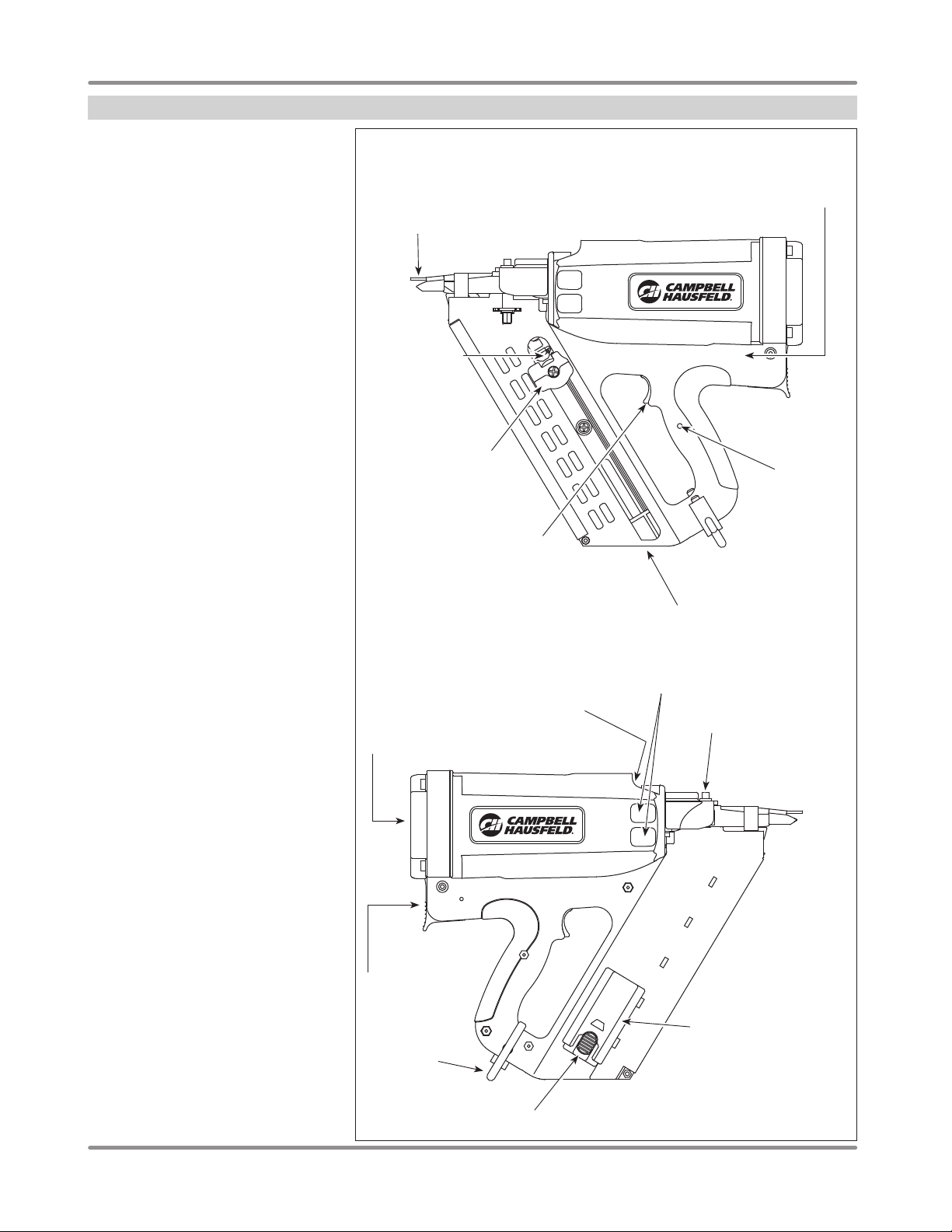
Getting To Know Your Cordless Framing Nailer
ANTI-DRY FIRE
This tool is equipped with an Anti-Dry Fire
feature. This prevents the Work Contact
Element (WCE) from being pushed in
when only a few nails remain. Simply load
new nail clip behind remaining nails to
continue shooting.
BATTERY INDICATOR LIGHT
The tool is equipped with an LED light to
indicate operation condition of the battery
of the tool. The LED has the following
functions:
Flashing GREEN light: Power remaining
for use.
Steady GREEN light: Remains on during
operation of the tool.
Flashing RED light: Insufficient power
remaining; charge battery.
Fast Flashing RED light: DO NOT
operate tool - possible malfunction; see
Troubleshooting section.
ADJUSTABLE DEPTH CONTROL
This allows the tool to adjust the depth
in which the fastener is placed into the
workpiece. For some applications, the
depth control will need to be adjusted
so that the fastener is flush or above the
work surface.
Work
Contact
Element
(WCE)
Pusher
Release
Button
Pusher Handle
NF349099
Manufacturer
Date Code
LED Battery
Status
Indicator
Trigger
Fastener
Loading
Area
Grille Cover and
Intake Filter
Fuel Cell
Door
Utility Hook
Battery
Primary
Exhaust
Area
Exhaust
Area
Adjustable Depth
Control
Battery Cover/
Compartment
www.chpower.com
6
Page 7
Operating Instructions and Parts Manual
Setup
Read all instructions for tool setup BEFORE putting the tool into use.
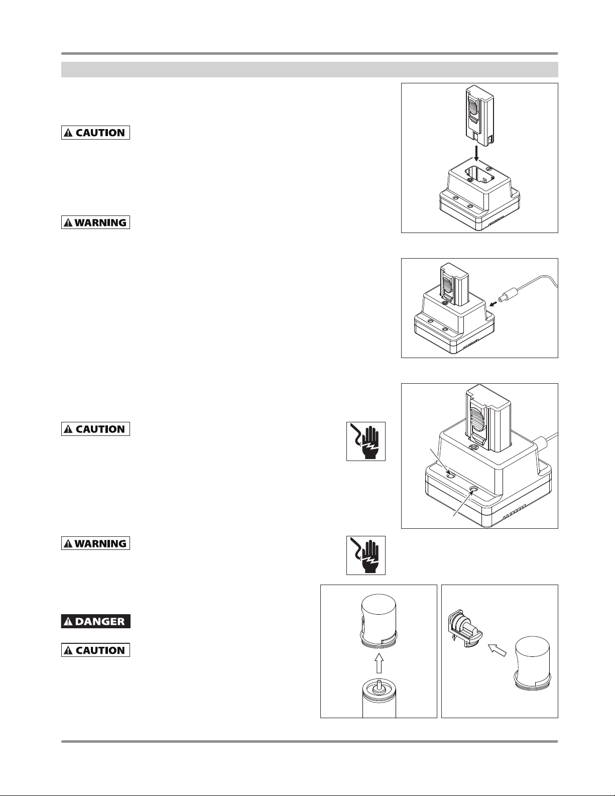
CHARGING BATTERY
Before using the tool, make sure battery is fully charged.
You must charge the battery before using the tool. Only use the
battery meant for this tool. Do not use or attempt to use other
battery types with this tool.
Setup the charger and charge the battery fully before first use of the tool.
Before plugging the charger into the outlet receptacle:
◆ Make sure the voltage on the charger base and adaptor is compatible with the
outlet receptacle
◆ Make sure the power cord of the charger system is not damaged
Do not charge the battery at a voltage higher than indicated on the
charger. This may cause damage to the battery or the charger.
To charge the battery, do the following:
1. Place the battery into the charger (see Figure 1). Make sure the battery is securely in
the charger.
2. Plug the adaptor into the outlet receptacle.
3. Insert the power cord of the adaptor into the charger base (see Figure 2).
4. Charging will begin as soon as the charger and adaptor are connected (see
Figure 3). The green LED light on the charger will turn on continuous to indicate
charging has begun. If the LED light does not turn on, remove battery and reinsert
battery back into charger base. The battery is fully charged when the green LED on
the charger base is flashing. Once the battery is fully charged, remove the battery
from charger. DO NOT leave it on continuous charge to avoid possible damage to
the battery.
5. The red LED light will turn on if a problem exists.
NOTE: The battery charging time can be affected by the temperature of the area where
the charger is being used.
6. Once charged, unplug the battery charger adaptor from the outlet receptacle.
Do not pull the adaptor out of the outlet receptacle
by pulling on the adaptor cord. This could cause the
cord to break and may cause electrical shock or property damage. If the
cord is yanked and damaged, DO NOT use for charging. Exposed wires can
cause an electrical shock.
7. Remove the battery from the battery charger.
Hints to extend battery life:
◆ Recharge the battery before it is completely exhausted.
◆ Avoid recharging the battery at high temperatures.
◆ After charging, wait for the battery to cool to room temperature before use.
Do not immerse battery or charger in water for any
reason. Serious shock and damage to unit may occur.
NF349099
Figure 1
Figure 2
Red
LED
Green LED
Figure 3
FUEL CELL PREPARATION
See fuel cell manufacturer instructions for instructions, warnings,
and disposal information.
The fuel cell is fl ammable. Keep away from
open fl ame or any source which may ignite the
fuel cell.
If the gas of the fuel cell leaks from the
metering valve or the fuel cell itself after
attaching the metering valve, replace with a new metering valve.
Do not attempt to reuse the metering valve.
To attach the metering valve to a fuel cell, do the following:
1. Remove shipping cap / metering valve from the fuel cell, if
applicable. See Figure 4.
2. Remove the metering valve from the protective cap, if
applicable. See Figure 5.
Figure 4 Figure 5
www.chpower.com
7
Page 8
Operating Instructions and Parts Manual
Setup (Continued)
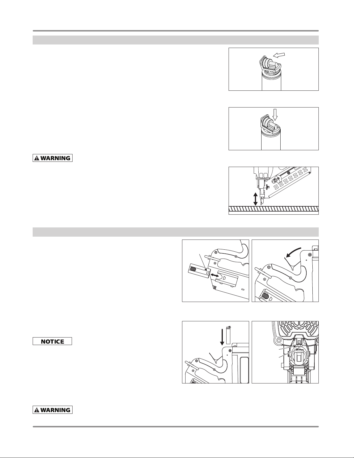
3. Attach the metering valve to the top of the fuel cell with the stem pointing away from
your face and body (see Figure 6).
4. Insert the front ridge of the metering valve into the lip of the fuel cell (see Figure 6).
5. Push down firmly on the rear of the metering valve. You will hear a “click” sound (see
Figure 7). Push down again on the rear of the metering valve. You will hear a second
“click” sound (see Figure 7). The second “click” sound indicates that the metering
valve is seated correctly on the fuel cell.
6. In a well-ventilated area, test the fuel cell by pressing the valve ejection tip against
a test surface. Do NOT aim or direct toward face or other people. Keep away from
sparks and flame. Allow a small amount of the aerosol fuel to dispense. If the fuel
does not dispense, the metering valve is not installed correctly or the fuel cell is
damaged / empty. Properly discard the fuel cell and restart this procedure with a new
fuel cell.
TOOL PREPARATION
At this point, the tool should not be loaded with fasteners. The battery and fuel cell
should not be inserted either.
NEVER use this tool if the Work Contact Element (WCE) is not
operating properly.
Pull pusher handle back to the bottom of the magazine until it locks into position.
Test the WCE by placing against a solid surface and depressing the nose as you would
for normal use. DO NOT pull the trigger. Remove the tool from the work surface. The
WCE should move smoothly up and down as it is placed against and removed from the
work surface (see Figure 8).
If the WCE does not move smoothly, DO NOT use the tool; call customer service for
assistance (1-800-543-6400).
Using the proper allen wrench and a small Phillips screwdriver, make sure all screws
and/or socket head cap bolts are securely in place. DO NOT overtighten.
NF349099
Figure 6
Figure 7
Figure 8
Pre-Operation
INSERT BATTERY
1. Load the battery, contacts first, into the tool (see Figure 9).
2. Push battery forward into the locked position.
3. To remove the battery, push on locking tab; slide battery out.
NOTE: If battery remains in tool, unused, for an extended period of
time, the battery will fully deplete its charge. Check the battery first
for charge status before returning tool to use.
NOTE: If battery contact terminals become corroded or dirty, it may
cause the tool to malfunction. Clean the contact terminals using a
fine emery cloth. Do not submerge the battery in water or use any
type of cleaning solution on contact terminals.
INSERT FUEL CELL
Metering valve must already be attached to fuel cell as explained in
Fuel Cell Preparation section.
fuel cell and/or tool.
1. Pull fuel cell door upward and tilt door outward to open. The fuel
cell door will swing toward the tool handle (see Figure 10).
2. Insert fuel cell, base first, into tool with metering valve pointed
toward the tool’s red gas valve (see Figure 11).
3. Insert the stem of the metering valve into the small hole of the
red gas valve. (See Figure 12).
4. Close the fuel cell door. Push down until door “clicks” into
position.
Refer to safety instructions and warnings
Do NOT expose fuel cell to temperatures above manufacturer’s
recommended limit.
Do not install fuel cell without the metering
valve properly attached. This may damage the
provided by fuel cell manufacturer.
Battery
Contact
Figure 9
Figure 11 Figure 12
Figure 10
Red
Gas Valve
Fuel Cell
Stem
www.chpower.com
8
Page 9
Operating Instructions and Parts Manual
Pre-Operation (Continued)
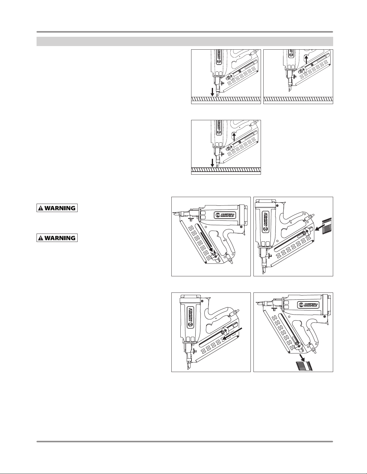
PRE-USE TEST
Before loading the tool, test the nailer to ensure proper operation.
Pull pusher handle back to the end of the magazine until it locks
into position.
1. Keep finger OFF the trigger. Depress the WCE by placing nose
of tool against a solid surface and depressing the nose as
you would for normal use. The tool MUST NOT actuate (see
Figure 13). At this point, the tool should eject a small, metered
quantity of fuel into the combustion chamber. The tool fan
should start, dispersing any gaseous exhaust.
2. Remove tool from work surface. Pull the trigger and hold trigger
for five seconds. The tool MUST NOT actuate and the trigger
SHOULD NOT fully depress (see Figure 14).
3. REMOVE finger from the trigger. Depress the WCE by placing
nose of tool against a solid surface and depressing the nose
as you would for normal use. Pull the trigger. The tool MUST
actuate (see Figure 15).
If the tool performs as expected in the three steps above, the tool is
ready to be loaded with fasteners.
LOADING AND UNLOADING
Disconnect the battery and fuel cell
from the tool before loading or
unloading the tool. Such precautionary measures reduce
the risk of injury to persons.
Loading the Tool
When loading fasteners into the tool,
DO NOT depress the trigger, DO NOT
depress the work contact element, and keep the tool
pointed in a safe direction.
To load the tool, do the following:
1. Pull the fastener pusher to the bottom of the magazine
until the fastener pusher is locked in place (see
Figure 16).
2. Insert nail strip into the back of the magazine (see
Figure 17).
3. Press down on the fastener pusher button and guide
the fastener pusher up to meet the bottom of the clip
of nails placed in the magazine (see Figure 18).
NOTE: DO NOT release the fastener pusher knob to spring
back towards the clip of nails loaded into the magazine.
This can damage the nail clip and could cause the tool to
jam.
The tool is now ready for use. See Operation section of
this manual for tool use instructions.
Unloading the Tool
1. Pull the fastener pusher to the bottom of the magazine
until the fastener pusher is locked in place (see
Figure 16).
2. Turn tool to the upright position. All remaining nails
in magazine will slide out the bottom of the magazine
(see Figure 19).
NF349099
Figure 13 Figure 14
Figure 15
Figure 17Figure 16
Figure 19Figure 18
www.chpower.com
9
Page 10
Operating Instructions and Parts Manual
Operation
LUBRICATION
This nailer requires NO regular lubrication for normal operation. Lubrication is done
during service periods.
The work surface can become damaged by excessive lubrication.
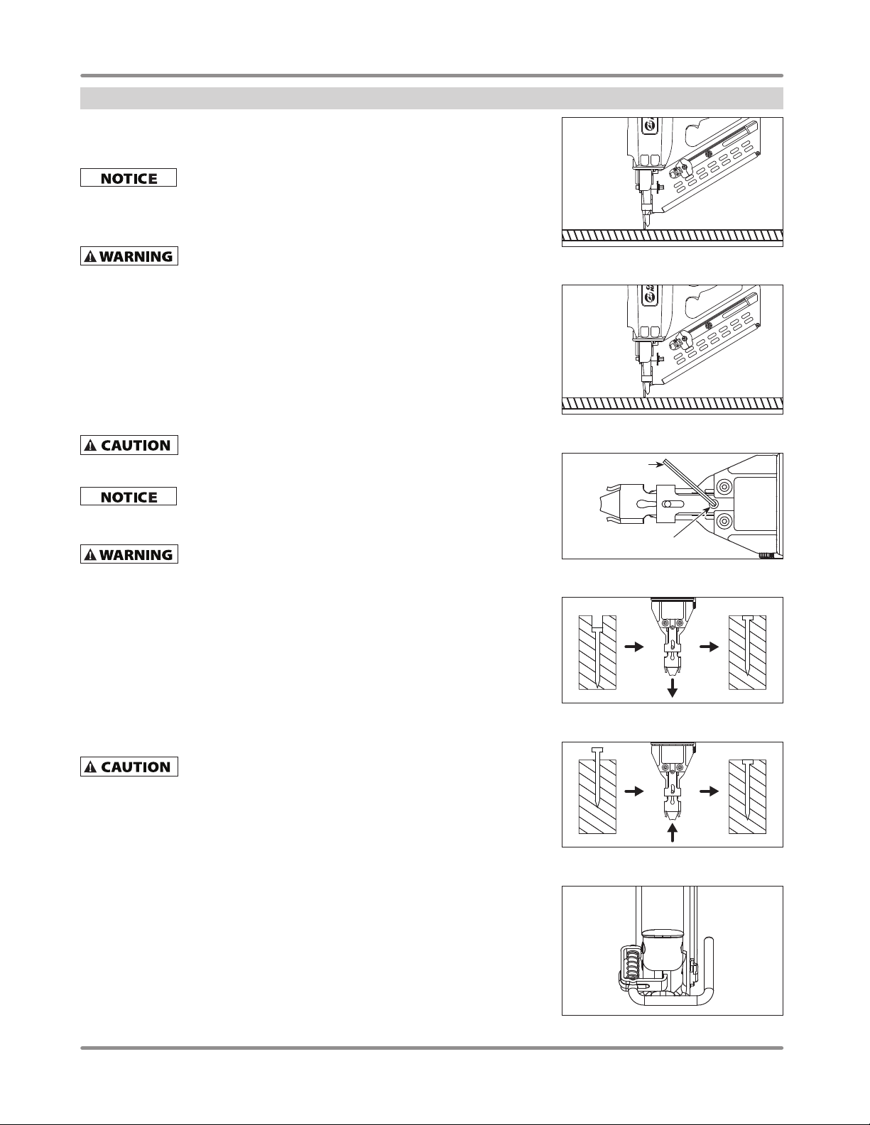
FIRING THE TOOL
With the fuel cell, battery, and fasteners loaded, the tool is ready for use.
NEVER use this tool if the Work Contact Element (WCE) is not
1. Position tool where fastener is to be driven. DO NOT pull trigger or even hold tool
with finger on trigger until position is set on the workpiece (see Figure 20).
2. Press the WCE against the surface of the workpiece until it is in the fully depressed
position (see Figure 21).
3. Briefly pull trigger and release. The tool will cycle and drive a fastener into the
workpiece.
4. Lift tool from surface of workpiece and the WCE will return to original position. The
trigger must be released after each fastener is driven to allow the tool to reset; the
WCE will not return to original position until trigger is released.
Repeat this process at the next position where a fastener is needed.
This tool has an Anti Dry Fire (ADF) lockout feature that will not
reached a low fastener count. The count ranges from 5 to 8 fasteners depending on
the type gauge, coating, shank deformity, etc.
DO NOT further attempt to forcefully depress WCE when ADF
operating properly.
allow the tool to operate when the nail supply in the magazine has
has engaged. Tool damage MAY occur.
NF349099
Figure 20
Figure 21
Allen Wrench
ADJUSTING FASTENER DEPTH
NEVER make adjustments to the tool with fasteners in the
magazine. Remove fasteners from magazine to prevent accidental
discharge of fastener. Remove fuel cell and battery before making adjustments.
1. With the fuel cell, battery, and fasteners removed, loosen the adjustable depth
control (ADC) socket head cap screw with 4mm allen wrench (see Figure 22).
2. If nails are driven too deep into work surface, move the work contact element down
(or away) from tool body (see Figure 23).
3. If nails are driven too shallow into work surface, move the work contact element up
(or toward) to tool body (see Figure 24).
4. Once adjustments are made, tighten the ADC screw. Reload the tool magazine,
insert the fuel cell and battery. Drive another fastener. If the fastener depth is still not
correct, repeat steps above.
UTILITY HOOK
If the tool falls, there is a risk of mechanical malfunction. There
is also a risk of physical injury if the tool discharges a fastener as
a result of being dropped.
Use the hook at the base of the tool handle to secure the tool to a solid support. When
using the hook, pull the hook away from the tool fully. If not using the hook, keep it
closed to prevent it from catching at the work site (see Figure 25). Do not use the hook
to attach the tool to your body.
ADC Screw
Figure 22
Figure 23
Figure 24
www.chpower.com
10
Figure 25
Page 11
Operating Instructions and Parts Manual
Maintenance
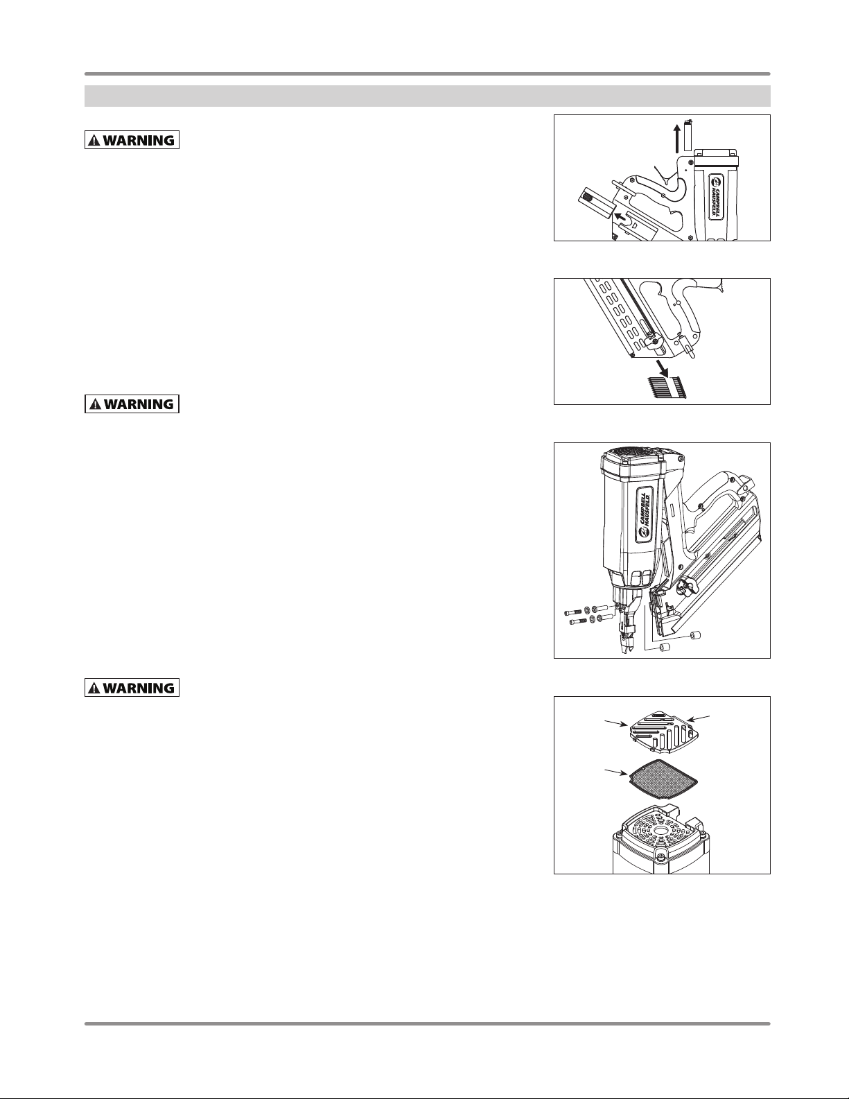
CLEARING A JAM
ALWAYS wear ANSI Z87 compliant safety glasses when using tool
or making any adjustments or repairs.
If the tool becomes jammed, do the following to clear
the jam:
1. Remove the fuel cell and battery from the tool (see Figure 26).
2. Pull the fastener pusher to the bottom of the magazine and remove all remaining
fasteners from the magazine (see Figure 27).
3. Remove the socket head cap bolts with allen wrench (see Figure 28).
4. Pull magazine away from head assembly (see Figure 28). Remove the jammed
fasteners.
5. Return head assembly and magazine to original position. Insert and tighten socket
head cap bolts.
TOOL REPAIR AND REPLACEMENT PARTS
Only qualified personnel should repair the tool and they should use genuine Campbell
Hausfeld replacement parts and accessories, or parts and accessories which perform
equivalently.
Use only genuine Campbell Hausfeld service parts. Tool
performance, safety, and durability could be reduced if improper
parts are used. When ordering replacement parts, specify by part number.
ASSEMBLY PROCEDURE FOR SEALS AND MOVING PARTS
When repairing or servicing a nailer, the internal parts must be cleaned and lubricated. A
compatible lubricant must be used on all o-rings. Each o-ring must be coated with the
lubricant before assembling. A small amount of oil must be used on all moving surfaces
and pivots. After reassembling, a few drops of 30W non-detergent oil or equivalent,
must be added one time before normal operational use.
NF349099
Figure 26
Figure 27
AIR FILTER
Open fuel cell door. Remove air exhaust cover (grille) by pressing on grille and turning
grille slightly out toward the top of the tool. The filter is held in place by the grille; filter
should lift out of place easily (see Figure 29). Remove all large particulates from the
grille and wash with a mild soap and water. Check and clean the filter on a regular basis
before and after regular use. We recommend cleaning the filter every other day and
before and after tool is placed in storage for any long period of time.
STORAGE
Store tool properly with fuel cell and battery removed.
Remove all fasteners from the tool.
◆ Store nailer in a cool, dry location. Do not store in a warm location or a location that
will possibly increase to temperatures above 120°F (49°C).
◆ Make sure stored tool is out of the reach of children; use storage case to help
secure the tool. Use storage case to store components of tool separately.
TECHNICAL SERVICE
For information regarding the operation or repair of this product, please call
1-800-543-6400.
Figure 28
Figure 29
Grille
Filter
Figure 29
Press here
to remove
grille from
tool
www.chpower.com
11
Page 12

Operating Instructions and Parts Manual
Troubleshooting Guide
NF349099
Stop using nailer immediately if any of the following problems occur. Serious personal injury could result.
Any repairs or replacements must be done by a Qualifi ed Service Person or Authorized Service Center.
Problems with Battery and/or Battery Charger
SYMPTOM CAUSE SOLUTION
Battery will not charge when
placed in battery charger.
Tool’s fan operates slowly,
does not function and/or tool
LED on tool handle is flashing
or solid red.
Charger becomes hot, makes
loud noises, or creates smoke
during charging process.
1. Defective or malfunctioning charger 1. Replace the charger.
2. LED lights on battery charger or tool
not working
3. Battery damaged or battery life cycle
expired
1. Battery is not charged 1. Charge the battery.
2. Battery contact terminals are dirty or
obstructed
Damaged charger Remove charger from use. Unplug charger. Replace
Call 1-800-543-6400 for assistance.
2. Insert the battery into the tool and attempt normal
operation. If tool does not work, replace charger.
Power supply or charging base not plugged in.
Call 1-800-543-6400 for assistance.
3. Replace the battery.
Call 1-800-543-6400 for assistance.
2. Clean the battery contact terminals with a fine
emery cloth.
charger.
Problems with Fuel Cell
SYMPTOM CAUSE SOLUTION
Tool will not drive fastener,
but fan runs and LED on tool
handle is green.
1. Fuel cell is empty 1. Replace fuel cell.
2. Fuel cell is damaged or leaking 2. Replace fuel cell.
3. Metering valve popped off fuel cell
head
4. Damaged gas valve 4. Allow tool and fuel cell to cool down. Replace gas
3. Allow tool and fuel cell to cool down. Reinstall
meter valve to fuel cell and reinstall fuel cell into
tool.
valve.
General Problems
SYMPTOM CAUSE SOLUTION
Work Contact Element (WCE)
does not depress or does
not depress fully. Tool’s fan
will not operate when WCE is
depressed.
Tool operates, but no fastener
is driven.
Fasteners jam. Fastener driver
is bent.
Tool cycles in a weak, errant,
or erratic way between driving
fasteners.
1. WCE is bent or damaged 1. Check for an obstruction or jammed fastener. DO
2. Fastener pusher is not seated behind
the loaded fasteners
3. Screws loose 3. Check connections and tighten if necessary.
4. Magazine empty or low 4. Load fasteners.
5. Problem with the battery 5. Check tool LED color. If the LED is red, charge
1. Fastener jam 1. Clear jam as instructed in Maintenance section.
2. Fastener pusher malfunction 2. Unload fasteners, check fastener pusher operation,
3. Magazine spring weak or damaged 3. Replace spring in magazine.
4. Wrong type fasteners loaded 4. Remove fasteners and check compatibility.
5. WCE is stuck or wedged 5. Check WCE for proper operation.
6. Tool skipped and/or driver did not
retract due to a difficulty during
operation
1. Wrong type fasteners loaded 1. Remove fasteners and check compatibility.
2. Driver blade worn or damaged 2. Call 1-800-543-6400 for assistance and
Dirty exhaust valve and / or muffler Clean with degreaser cleaner (see Cleaning Instructions
NOT put tool into use until WCE operates correctly.
2. Unload magazine and reload per the loading
instructions.
battery. If the LED is green, call 1-800-543-6400 for
assistance.
and/or clean magazine.
Call 1-800-543-6400 for assistance.
Only use compatible fasteners.
6. Remove fasteners, battery, and fuel cell. Manually
press driver back into tool with a long, thin
screwdriver.
Only use compatible fasteners.
replacement part.
manual). Repair or replace deformed valve.
www.chpower.com
12
Page 13

Operating Instructions and Parts Manual
Troubleshooting Guide
NF349099
Stop using nailer immediately if any of the following problems occur. Serious personal injury could result.
Any repairs or replacements must be done by a Qualifi ed Service Person or Authorized Service Center.
General Problems (Continued)
SYMPTOM CAUSE SOLUTION
Driver blade of tool does not
operate smoothly or return to
pre-fire position.
Tool operates properly, but
fastener does not drive
completely into work surface.
Tool operates erratically.
Tool LED is green.
Tool does not fire fastener
every time trigger is pulled.
Tool does not drive fastener.
Fan comes on, fuel cell is
confirmed to have fuel, and
WCE moves freely.
1. Driver blade is dirty or debris is in
pathway
2. Driver blade is bent 2. Do not use tool.
3. Exhaust valve dirty or deformed due to
excessive usage and heat
4. Filter is blocked or dirty; tool is
overheating
5. Screws loose 5. Check connections and tighten if necessary.
1. Fastener depth adjust not set correctly 1. Follow instruction in Operation section for
2. Fuel cell is low 2. Check fuel cell, metering valve connection, and/or
3. Leak in fuel system 3. Depress WCE against the work surface and hold in
1. Fuel cell is low 1. Check fuel cell. Replace fuel cell if necessary.
2. Malfunction in electrical components 2. Call 1-800-543-6400 for assistance.
3. Filter is blocked or dirty; tool is
overheating
4. Tool is dirty 4. Clean tool.
5. Filter is blocked or dirty; tool is
overheating
6. Screws loose 6. Check connections and tighten if necessary.
1. Check fasteners 1. Remove fasteners and check compatibility.
2. Fastener pusher malfunction 2. Unload fasteners, check fastener pusher operation,
3. Magazine spring weak or damaged 3. Replace spring in magazine.
4. Driver blade worn or damaged 4. Call 1-800-543-6400 for assistance and
5. Check driver blade of tool has returned
to pre-fire position
6. Driver blade is dirty or debris is in
pathway
7. Filter is blocked or dirty; tool is
overheating
8. Screws loose 8. Check connections and tighten if necessary.
1. Dirty or worn spark plug 1. Remove and clean spark plug. Reinsert spark plug
2. Check wiring for breaks or
disconnected plugs
1. Remove battery and fuel cell, then clean driver
blade pathway or remove debris.
Call 1-800-543-6400 for assistance.
3. Remove battery, fasteners, and fuel cell. Clean if
dirty and replace if deformed.
4. Remove and clean filter.
Adjusting Fastener Depth.
replace with new fuel cell if necessary.
place for a few seconds. Pull the trigger to actuate
tool. Fastener should drive into work surface. If no
fastener is driven, there may be a leak in the fuel
delivery system.
Discontinue use and call 1-800-543-6400 for
assistance.
3. Remove filter element and clean; inspect exhaust
and remove any debris or blockage. Allow tool to
cool down if exhaust port is warmer to the touch
than when in normal use.
5. Remove and clean filter.
Only use compatible fasteners.
and/or clean magazine.
Call 1-800-543-6400 for assistance.
replacement part.
5. If driver blade is not in pre-fire position, the trigger
was not pulled all the way. Depress WCE against
scrap piece work surface and pull trigger. This
should return driver blade to pre-fire position. If it
does not, remove fasteners, battery, and fuel cell.
Call 1-800-543-6400 for assistance.
6. Remove battery and fuel cell, then clean driver
blade pathway or remove debris.
7. Remove and clean filter.
and attempt to operate. If still not working, replace
spark plug.
2. Replace plug and / or wiring harness and / or
e-module (in that order).
www.chpower.com
13
Page 14
Operating Instructions and Parts Manual
NF349099
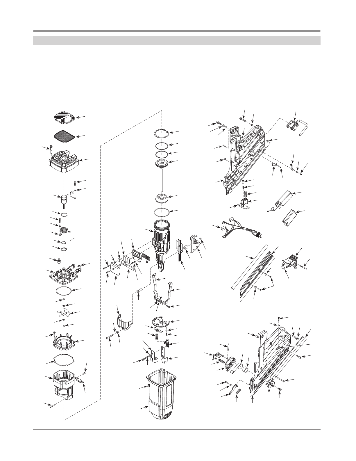
Replacement Parts Illustration
For Replacement Parts or Technical Assistance,
Call 1-800-543-6400
Please provide following information: Address any correspondence to:
- Model number Campbell Hausfeld
- Serial number (if any) Attn: Customer Service
- Part description and number as shown in parts list 100 Production Drive
Harrison, OH 45030 U.S.A.
62
79
15
49
106
107
72
74
75
84
111
1
43
42
63
104
105
64
65
73
76
66
40
41
2
3
4
5
6
7
8
5
6
37
31
33
32
109
38
46
13
12
9
10
11
14
25
102
6
36
34
112
35
26
27
27
28
29
30
44
45
83
51
71
82
68
67
70
69
77
78
80
81
15
16
18
20
21
22
Figure 30
14
16
17
15
19
23
www.chpower.com
24
49
57
52
56
59
60
61
39
103
58
56
53
49
51
93
98
99
89
84
91
24
6
92
85
90
86
88
87
18
47
6
49
50
55
48
54
94
95
96
97
108
110
100
101
Page 15

Operating Instructions and Parts Manual
◗
◗
◗
✤
◗
◗
▲
▲
◗
◗
◗
◗
●
◗
●
●
●
◗
◗
■
◆
◆
◆
✖
▼
Replacement Parts List
NF349099
Ref.
No. Description
1 Grille
2 Filter
3 Socket head cap screw
4 Top cover
5 Ground screw, M4 x 10
6 Spring washer
7 Motor
8 Wire ring
9 Motor mount bracket
10 O-ring, 22 x 2
11 Retaining ring
Part
Number Qty.
▲
▲ ■
▲
▲
●
● ✖ ✤
●
●
●
●
●
12 Spark plug NF000100AV ■ 1
13 Cylinder head NF000200AV 1
14 O-ring, 66.3 X 3.5
15 Motor shaft nut
16 Washer
17 Fan blade
18 Screw, M4 x 16
19 Combustion chamber ring
20 Combustion chamber seal
21 Combustion chamber
22 Pin
23 Combustion chamber plate
24 Screw, M4 x 6
25 Nozzle
26 Retaining ring
27 Piston ring
28 Driver assembly
29 Bumper
30 Steel seal ring
31 Cylinder
32 Sieve
33 Exhaust baffle
34 Reed valve
35 Cover
36 Screw
37 Muffler
38 Screw
39 Front bushing
40 Nut
■
●
●
●
◆
◆
■
◆
◆
■ ◆
■ ◆
■
■ ▼ ★
▼
▼
■
■ ★
★
✖
✖
■ ✖
✖
✖
■ ✖
✖
◗
◗
10
Ref.
No. Description
1
1
4
1
4
41 Rear drive guide
42 Rear bushing
43 Front drive guide
44 Right WCE bracket
45 Left WCE bracket
46 WCE bracket connector
1
1
1
1
1
47 Screw, 34 x 8
48 Cylinder mounting plate
49 Spring washer
50 Screw, 10 - 24 x 14
51 Nut, M4
52 WCE spring cover
53 WCE spring cover
1
3
2
1
2
1
1
1
1
1
4
1
1
2
1
1
1
1
1
1
1
1
2
1
2
2
2
54 ADC tie plate
55 Work Contact Element (WCE)
56 Washer
57 ADC socket screw, M5 x 55
58 ADC adjustment bracket
59 Screw, M5 x 12
60 Threaded insert
61 Head housing
62 Screw, M5 x 16
63 Screw
64 Screw
65 Rubber screw cap
(right side), M4
66 Wiring harness and switch
assembly
67 Utility hook
68 Roller arm lever assembly
69 Screw
70 Washer
71 Screw
72 Clamp
73 Housing (right side)
74 Trigger spring
75 Trigger
76 Trigger lock rod
77 Electronic module with LED NF000300AV 1
78 Lithium ion rechargeable battery NF000400AV 1
79 Nail head guide
80 Fuel cell door
Part
Number Qty.
◗
◗
◗
✤
✤
✤
✤
✤
◗ ✤
✤
✤
◗
✤
✤
✤
◗ ✤
◗
✤
✤
1
2
1
1
1
1
2
1
7
2
3
1
1
1
1
3
2
1
1
4
1
1
2
1
4
1
1
1
1
1
1
1
1
1
1
1
1
1
www.chpower.com
15
Page 16

Operating Instructions and Parts Manual
NF349099
Replacement Parts Illustration
For Replacement Parts or Technical Assistance,
Call 1-800-543-6400
Please provide following information: Address any correspondence to:
- Model number Campbell Hausfeld
- Serial number (if any) Attn: Customer Service
- Part description and number as shown in parts list 100 Production Drive
Harrison, OH 45030 U.S.A.
62
79
15
49
106
107
72
74
75
84
111
1
43
42
63
104
105
64
65
73
76
66
40
41
2
3
4
5
6
7
8
5
6
37
31
33
32
109
38
46
13
12
9
10
11
14
25
102
6
36
34
112
35
26
27
27
28
29
30
44
45
83
51
71
82
68
67
70
69
77
78
80
81
15
16
18
20
21
22
Figure 31
16
16
17
15
19
23
www.chpower.com
24
49
57
52
56
59
60
61
39
103
58
56
53
49
51
93
98
99
89
84
91
24
6
92
85
90
86
88
87
18
47
6
49
50
55
48
54
94
95
96
97
108
110
100
101
Page 17

Operating Instructions and Parts Manual
▼
▼
✖
✖
◗
◗
◗
■
■ ◗
◗
★
★
■
★
★
★
★
★
★
★
★
◗
◗
◆
◆
★
★
★ ✖
▲
■
●
◆
▼
★
✖
◗
✤
Replacement Parts List (Continued)
NF349099
Ref.
No. Description
81 Fuel cell door pin
82 Rubber sleeve
83 Magazine cover plate
84 Washer
85 Screw
86 Rubber screw cap (left side)
87 Pusher catch plate
88 Magazine channel clamp
89 Housing (left side)
90 Screw
91 Pusher handle
92 Screw
93 LED light pipe
94 Pusher pin
95 Pusher
96 Pusher spring
97 Pusher housing
98 Coil spring
99 Bushing
100 ADF engagement plate
101 ADF spring
102 Washer
103 Spacer block
104 Washer
105 Bushing
106 Trigger cylinder
107 Trigger cylinder spring
108 Screw
109 Washer
110 Clamp washer
Part
Number Qty.
1
1
1
2
3
4
1
1
1
1
1
1
1
1
1
1
1
1
1
1
1
✖
✤
2
1
2
2
1
1
1
✖
2
1
Ref.
No. Description
111 Screw
112 Reed valve supporter
113 Charging base (not shown) NF000500AV
114 Charging base adaptor
(not shown)
115 Replacement latch for case
(not shown)
REPLACEMENT PARTS KITS
▲
Top cover kit NF000700AV
■
Rebuild kit NF000800AV
●
Fan motor kit NF000900AV
◆
Combustion chamber assembly NF001000AV
▼
Piston assembly NF001100AV
★
Cylinder kit NF001200AV
✖
Exhaust kit NF001300AV
◗
Drive guide kit (includes extra
nuts)
✤
WCE kit NF001500AV
Head housing kit NF001600AV
Housing kit NF001700AV
Wiring harness & switch kit NF001800AV
Trigger assembly NF001900AV
Fuel cell door kit NF002000AV
Pusher assembly kit NF002100AV
Nail guide kit NF002200AV
Housing hardware kit NF002300AV
Nozzle kit (set of 2) NF002500AV
-- Not Available
Part
Number Qty.
2
■ ✖
1
NF000600AV
NF002400AV
NF001400AV
www.chpower.com
17
Page 18

Operating Instructions and Parts Manual
NF349099
Reminder: Keep your dated proof of purchase for warranty purposes! Attach it to this manual or file it for safekeeping.
Limited Warranty
1. DURATION: From the date of purchase by the original purchaser as follows: One (1) Year.
2. WHO GIVES THIS WARRANTY (WARRANTOR): Campbell Hausfeld / Scott Fetzer Company, 100 Production Drive, Harrison,
Ohio, 45030, Telephone: (800) 543-6400
3. WHO RECEIVES THIS WARRANTY (PURCHASER): The original purchaser (other than for purposes of resale) of the Campbell
Hausfeld product.
4. WHAT PRODUCTS ARE COVERED BY THIS WARRANTY: This Campbell Hausfeld cordless nailer.
5. WHAT IS COVERED UNDER THIS WARRANTY: Substantial defects in material and workmanship which occur within the duration
of the warranty period with the exceptions below.
6. WHAT IS NOT COVERED UNDER THIS WARRANTY:
A. Implied warranties, including those of merchantability and FITNESS FOR A PARTICULAR PURPOSE ARE LIMITED FROM
THE DATE OF ORIGINAL PURCHASE AS STATED IN THE DURATION. If this product is used for commercial, industrial or
rental purposes, the warranty will apply for ninety (90) days from the date of purchase. Some States do not allow limitation
on how long an implied warranty lasts, so the above limitations may not apply to you.
B. ANY INCIDENTAL, INDIRECT, OR CONSEQUENTIAL LOSS, DAMAGE, OR EXPENSE THAT MAY RESULT FROM ANY
DEFECT, FAILURE, OR MALFUNCTION OF THE CAMPBELL HAUSFELD PRODUCT. Some States do not allow the exclusion
or limitation of incidental or consequential damages, so the above limitation or exclusion may not apply to you.
C. Any failure that results from an accident, purchaser’s abuse, neglect or failure to operate products in accordance with
instructions provided in the owner’s manual(s) supplied with product. Accident, purchaser’s abuse, neglect or failure to
operate and clean products in accordance with instructions shall also include the removal or alteration of any safety devices.
If such safety devices are removed or altered, this warranty is void.
D. Normal adjustments and cleaning which are explained in the owner’s manual(s) provided with the product.
E. Items or service that are normally required to maintain the product, e.g. o-rings, springs, bumpers, driver blades, batteries,
gaskets, packings or seals, lubricants, reed valve, or any other expendable part not specifically listed. These items will only
be covered for ninety (90) days from date of original purchase. Underlined items are warranted for defects in material and
workmanship only.
7. RESPONSIBILITIES OF WARRANTOR UNDER THIS WARRANTY: Repair or replace, at Warrantor’s option, products or
components which are defective, have malfunctioned and/or failed to conform within the duration of the specific warranty period.
8. RESPONSIBILITIES OF PURCHASER UNDER THIS WARRANTY:
A. Provide dated proof of purchase and maintenance records.
B. Deliver or ship the Campbell Hausfeld product or component to the nearest Campbell Hausfeld Authorized Service Center.
Freight costs, if any, must be borne by the purchaser.
C. Use reasonable care in the operation and maintenance of the products as described in the owner’s manual(s).
9. WHEN WARRANTOR WILL PERFORM REPAIR OR REPLACEMENT UNDER THIS WARRANTY: Repair or replacement will
be scheduled and serviced according to the normal work flow at the servicing location, and depending on the availability of
replacement parts.
This Limited Warranty applies in the United States, Canada and Mexico only and gives you specific legal rights. You may also have
other rights which vary from state to state or country to country.
www.chpower.com
18
Page 19

Instructions d’Utilisation et Manual de Pièces
Cloueuse
d’Encadrement sans Fil
ENREGISTREZ VOTRE PRODUIT EN LIGNE MAINTENANT ! http://www.chpower.net/reg
Description
Cette cloueuse à essence est conçue pour l’encadrement, les fermes de toit, les sousplanchers, le revêtement, les terrasses extérieures et l’assemblage de palettes/caisses.
Les caractéristiques incluent : magasin pratique à chargement arrière contenant environ
40 clous, un réglage de pénétration des clous, un chargeur en ligne, une anti-décharge
à sec, un crochet utilitaire réglable et un voyant de batterie. Nécessite : Batterie et pile à
combustible pour le fonctionnement.
Cet outil utilise un mélange d’essence et d’air enflammé par une étincelle lui permettant
d’activer le processus d’entraînement des attaches. C’est un outil électrique
entièrement autonome qui libère l’utilisateur des restrictions associées aux cordons
d’alimentation et aux boyaux d’air.
Trouver le numéro de modèle et le code de date sur le chargeur et/ou le corps de l’outil.
Inscrire plus bas:
Nº du Modèle : ________________________________
Code Date : ___________________________________
Conserver ces numéros comme référence.
Spécifications
Modèle NF349099
Exigences : Batterie et pile à
combustible
Plage de tailles d’attaches :
◆ 2 à 3-1/2 po (5,08 à
8,89 cm ) de longueur.
◆ 0,28 à 0,33 cm (0,113 à
0,131 po) de diamètre de tige
◆ 30° à 34°
Capacité du chargeur :
40 attaches et plus par chargement
Poids :
3,37 kg (7 lb, 7 oz) [outil seul]
3,54 kg (7 lb, 13 oz) [avec
batterie et pile à combustible]
Longueur : 11-1/2 po (29,21 cm)
Hauteur : 15-1/4 po (38,74 cm)
Capacité de cycles :
Limité : Environ un clou à la
seconde
Continu : 1 000 clous par heure
Batterie : Li - ion 7,4 V c.c.
1,2 Ah
Poids de la batterie : 68,04 g
(0,15 lb)
Chargeur de batterie :
Entrée :
Monophasé de c.a. 100 – 240 V
50 - 60 Hz
Sortie :
9,5 V c.c.
1 200 mA
Temps de charge estimé :
5 minutes (200 clous)
120 minutes (3 000 clous)
Pile à combustible :
Environ 1 200 à 1 400 coups par
pile à combustible
Environnement de
fonctionnement :
Température de fonctionnement :
Minimum 0 °C (32 °F) à
un maximum de 40 °C (104 °F)
Altitude de fonctionnement :
0 à 1 219 m (0 à 4 000 pi)
au-dessus du niveau de la mer
ENGLISH: Page 1
ESPAÑOL: Página 37
© 2012 Campbell Hausfeld/Scott Fetzer
CONSERVER CES INSTRUCTIONS
NE LES JETEZ PAS
IN742700AV 8/12
Page 20

Instructions d’Utilisation et Manual de Pièces
NF349099
Directives de Sécurité
Ce manuel contient de l’information
très importante qui est fournie pour
la SÉCURITÉ et pour ÉVITER LES
PROBLÈMES D’ÉQUIPEMENT.
Rechercher les symboles suivants
pour cette information.
Danger indique
dangereuse imminente qui MÈNERA
à la mort ou à des blessures graves
si elle n’est pas évitée.
Avertissement
situation potentiellement
dangereuse qui, si elle n’est pas
évitée, POURRAIT mener à la mort
ou à de graves blessures.
Attention
situation potentiellement
dangereuse qui, si elle n’est pas
évitée, PEUT mener à des blessures
mineures ou modérées.
Avis indique de
importante qui pourrait
endommager l’équipement si elle
n’est pas respectée.
une situation
indique une
indique une
l’information
IMPORTANT : Information qui exige
une attention spéciale.
Symboles de sécurité
Les symboles de sécurité suivants
apparaissent dans l’ensemble de
ce manuel pour vous aviser des
dangers et précautions importants
de sécurité.
Porter une
protection
oculaire et un
masque.
Risque de
tomber
Risque
d’incendie
Présence
possible de
composants
chauds
Lire le manuel
d’abord
Porter une
protection
oculaire.
Risque
d’explosion
Présence
possible de
vapeurs
Risque de
blessure
Porter une
protection
auditive
Risque de
choc
Interdiction de
fumer
Directives de sécurité. . . . . . . . . . . F-20
Symboles de sécurité. . . . . . . . . . . F-20
Information importante sur
la sécurité. . . . . . . . . . . . . . . . . . . . F-20
Déballage . . . . . . . . . . . . . . . . . . . F-23
Glossaire . . . . . . . . . . . . . . . . . . . . . F-23
Apprendre à connaître votre
cloueuse d’encadrement sans fil . . F-24
Montage . . . . . . . . . . . . . . . . . . . . . F-25
Charger la batterie. . . . . . . . . . . . F-25
Préparation de la
pile à combustible. . . . . . . . . . . . F-25
Préparation de l’outil . . . . . . . . . . F-26
Pré-opération . . . . . . . . . . . . . . . . . F-26
Insérer la batterie. . . . . . . . . . . . . F-26
Insérer la pile à combustible . . . . F-26
Vérification avant utilisation . . . . F-27
Chargement / déchargement
de l’outil. . . . . . . . . . . . . . . . . . . . F-27
Information Importante sur la Sécurité
INSTRUCTIONS PORTANT SUR UN RISQUE D’INCENDIE, UN CHOC
ÉLECTRIQUE OU DES BLESSURES AUX PERSONNES
Ce manuel contient des informations concernant la sécurité, le fonctionnement et
l’entretien. Si vous avez des questions, appeler le 1-800-543-6400 pour le service à la
clientèle.
En utilisant les outils, il faut suivre les précautions de base, y
PROPOSITION 65 DE CALIFORNIE
Ce produit ou son cordon peuvent contenir des produits
et des anomalies congénitales ou autres problèmes de reproduction. Lavez-vous les
mains après la manipulation.
Vous pouvez créer de la poussière en coupant,
le bois, la peinture, le métal, le béton, le ciment ou autre maçonnerie. Cette
poussière contient souvent des produits chimiques reconnus pour causer le
cancer, les déformations congénitales.
GÉNÉRALITÉ :
a. Pour réduire les risques de chocs électriques, d’incendie ou de
blessures aux personnes, lire toutes les instructions avant d’utiliser
l’outil. Ne pas suivre les avertissements, les dangers et les mises en
garde pourrait causer la MORT ou de GRAVES BLESSURES.
b. Se familiariser avec ce produit, ses commandes et son utilisation. Suivez toutes
les instructions. Contacter votre représentant Campbell Hausfeld si vous avez des
questions.
c. Seules les personnes familières avec ces règles d’utilisation sans danger devraient
utiliser cette unité.
Ne pas utiliser la cloueuse ni permettre qu’une autre personne
situés sur le chargeur et corps de la cloueuse ne sont pas lisibles.
Toujours prendre pour acquis que la cloueuse contient des
un jouet. Donc aucun jeu brutal. Toujours garder les autres personnes à une distance
de sécurité de l’aire de travail en cas de décharge accidentelle des clous. Ne pas
pointer l’outil vers vous ou vers quelqu’un d’autre qu’il y ait ou non des attaches dans
la cloueuse. Le déclenchement accidentel de la cloueuse pourrait causer la mort ou de
graves blessures.
Ne pas apporter de modifi cations à l’outil sans d’abord obtenir
une cloueuse si les écrans ou protecteurs ont été enlevés ou altérés. Ne pas utiliser
la cloueuse comme un marteau. Cela peut entraîner des blessures ou endommager
l’appareil.
Table des Matières
Fonctionnement . . . . . . . . . . . . . . . F-28
Lubrification. . . . . . . . . . . . . . . . . F-28
Déclenchement de l’outil. . . . . . . F-28
Ajuster la profondeur
des attaches . . . . . . . . . . . . . . . . F-28
Crochet utilitaire . . . . . . . . . . . . . F-28
Entretien . . . . . . . . . . . . . . . . . . . . . F-29
Dégager un blocage . . . . . . . . . . F-29
Réparation de l’outil et
pièces de rechange. . . . . . . . . . . F-29
Méthode d’assemblage
des joints d’étanchéité et
des pièces mobiles . . . . . . . . . . . F-29
Filtre d’air. . . . . . . . . . . . . . . . . . . F-29
Entreposage . . . . . . . . . . . . . . . . F-29
Service Technique. . . . . . . . . . . . F-29
Guide de dépannage . . . . . . . . . . . F-30
Liste de pièces de rechange . . . . . F-34
Garantie . . . . . . . . . . . . . . . . . . . . . F-38
compris ce qui suit :
chimiques qui, de l’avis de l’État de Californie, causent le cancer
ponçant, perçant ou meulant les matériaux tels que
l’utilise si les avertissements ou les étiquettes d’avertissement
clous. Respecter l’outil comme accessoire de travail non pas
une approbation écrite de Campbell Hausfeld. N’utilisez pas
F-20
Page 21

Instructions d’Utilisation et Manual de Pièces
Information Importante sur la Sécurité (Suite)
AIRE DE TRAVAIL
a. Garder l’aire de travail propre et bien éclairée. Les
établis encombrés et les coins sombres augmentent les
risques de chocs électriques, d’incendie et de blessures
aux personnes.
b. Ne pas faire fonctionner l’outil dans une
atmosphère explosive comme en présence
de liquides, gaz ou poussières inflammables.
L’outil peut produire des étincelles menant à une
inflammation de poussières ou de fumées.
c. Garder les spectateurs, les enfants et les visiteurs loin
en utilisant l’outil. Les distractions peuvent faire perdre le
contrôle de l’outil.
SÉCURITÉ PERSONNELLE
a. Rester vigilant. Il faut regarder ce que vous faites et
utiliser son sens commun en faisant fonctionner un
outil. Ne pas faire fonctionner l’appareil si vous êtes
fatigué ou sous l’influence de drogues, d’alcool ou
de médicaments. Un moment d’inattention en faisant
fonctionner l’outil augmente le risque de blessures.
b. Il faut s’habiller correctement. Ne pas porter de bijoux
ou de vêtements amples. Attacher les cheveux longs.
Garder les cheveux, les vêtements et les gants loin des
pièces mobiles. Les vêtements amples, les bijoux ou les
cheveux longs augmentent le risque de blessures si quelque
chose se prend dans les pièces mobiles.
c. Ne pas trop se pencher. Garder bon pied
et bon équilibre en tout temps. Ceci permet
d’avoir un meilleur contrôle de l’outil dans les
situations imprévues.
d. Utiliser l’équipement de sécurité. Il faut
utiliser un masque antipoussières, des souliers de sécurité
antidérapants et un casque de protection appropriés pour
les conditions en cours.
S’assurer que l’outil est
utilisé seulement lorsque
l’opérateur et tout autre personnel dans l’aire de
travail portent un équipement de protection oculaire
ANSI Z87 et, s’il y a lieu, d’autre équipement de
protection approprié tel que de l’équipement de
protection pour la tête, les oreilles et les pieds. Il pourrait y
avoir de graves lésions oculaires ou perte auditive.
e. Toujours porter une protection auditive en
utilisant l’outil. Toute exposition prolongée à des
bruits de forte intensité pourrait provoquer une
perte auditive.
f. Ne pas attacher l’outil sur vous.
g. Toujours assumer que l’outil contient des
attaches. Ne pas pointer l’outil vers soi ou vers
quelqu’un d’autre qu’il y ait des attaches ou non.
Ne pas échapper ni jeter l’outil. Le fait
de faire tomber ou de jeter l’outil
risque de causer des dommages qui rendent l’outil inutilisable
ou dangereux. Si l’outil est tombé ou a été jeté, l’examiner
soigneusement afi n de déterminer s’il est coudé, fendu ou si
certaines pièces détachées sont endommagées. ARRËTER
et réparer l’outil avant utilisation sous peine de blessures
graves.
Éviter d’utiliser la cloueuse pour une
période de temps prolongée. Cesser
d’utiliser la cloueuse si l’on ressent des douleurs dans les
mains ou dans les bras.
NF349099
Tenir l’outil par des surfaces
de prise isolée en effectuant
le travail lorsque l’outil ou l’attache pourrait entrer
en contact avec un câblage caché. Un contact avec
un fi l « sous tension » rendra les pièces de métal
exposées de l’outil « sous tension » et produira un
choc pour l’opérateur.
Ne jamais placer les mains ou
toute autre partie du corps
dans la section de décharge des clous de la cloueuse.
L’outil pourrait décharger une attache menant à la
mort ou à de graves blessures.
h. Éloigner le visage, les mains et les pieds de la zone de
déclenchement de l’outil en cours d’utilisation. Ne jamais
approcher le visage, les mains et les pieds à une distance
inférieure à 20,32 cm (8 po) de la zone de déclenchement de
l’outil. Des blessures graves peuvent survenir si une attache
est déviée par la pièce de travail et revient vers l’outil.
Certaines pièces deviennent
chaudes en cours d’utilisation.
NE PAS toucher à mains nues. NE PAS toucher
l’orifice d’échappement de l’outil. L’outil produit
un échappement chaud pouvant contenir des gaz
inflammables. NE PAS toucher la pointe de contact
(PC) et la buse sans retirer la batterie et la pile à combustible;
laisser refroidir. La Pointe de contact (PC) et la buse deviendront
chaudes après une utilisation rapide ou prolongée.
SÉCURITÉ ÉLECTRIQUE
Remplacer les piles seulement
avec des piles de même taille.
Utiliser la mauvaise taille de pile peut créer un risque
d’incendie ou de blessure.
a. Ne jamais démonter la batterie.
b. NE PAS insérer d’objets dans les contacts de la batterie
ou les évents du chargeur de batterie. Il pourrait en
résulter une décharge électrique ou des dommages au
niveau de la batterie.
La partie avant de l’outil peut
devenir conductrice si l’outil
entre en contact avec des fils conducteurs se
trouvant dans le mur. POUR ÉVITER TOUTE
DÉCHARGE ÉLECTRIQUE ACCIDENTELLE,
TOUJOURS TENIR L’OUTIL PAR LA POIGNÉE À PRISE SOUPLE.
Inspecter l’espace de travail pour tout fil conducteur AVANT de
commencer à utiliser l’outil.
UTILISATION ET ENTRETIEN DE L’OUTIL
Ne pas modifi er ou altérer la pointe de
contact (PC). Ne pas attacher ou mettre
de ruban sur la PC ou sur la gâchette en position enfoncée.
Ceci pourrait mener à des blessures graves ou à la mort.
Toujours vérifi er que la pointe de contact
(PC) fonctionne correctement. Un clou
pourrait être entraîné accidentellement si la PC ne fonctionne
pas correctement. Des blessures graves pourraient en résulter.
Ne toucher à la gâchette qu’au moment
de poser des clous. Ne jamais actionner
la gâchette durant le transport ou durant l’installation de la
batterie ou de la pile à combustible. L’éjection accidentelle d’un
clou peut causer des blessures graves ou mortelles.
a. Ne pas forcer l’outil. Utiliser le bon outil pour l’application.
Le bon outil effectuera le meilleur travail sécuritaire au rythme
pour lequel il a été conçu.
Déconnecter la batterie et la pile à
combustible de l’outil avant d’effectuer
un réglage, l’entretien, un déblocage, ou avant de quitter l’aire
de travail ou de procéder au chargement ou au déchargement
de l’outil. Les mesures de précaution de ce type réduisent le
risque de blessures.
F-21
Page 22

Instructions d’Utilisation et Manual de Pièces
Information Importante sur la Sécurité (Suite)
b. Ranger l’outil lorsqu’il n’est pas utilisé hors de portée
des enfants et autres personnes non formées. Un outil
est dangereux dans les mains d’utilisateurs non formés.
c. Il faut entretenir l’outil avec soin. Un outil bien entretenu
réduit le risque de problèmes et est plus facile à contrôler.
d. Toujours travailler dans un endroit bien
ventilé. Porter un masque anti-poussières
homologué OSHA.
e. Utiliser l’outil à une plage de température sûre et
adéquate. L’environnement de fonctionnement de cet outil
se situe entre 0 °C (32 °F) et 40 °C (104 °F). L’outil peut ne
pas fonctionner correctement à des températures inférieures
ou supérieures à la plage de température indiquée.
Ne pas enfoncer de clou sur d’autres
provoquer la mort ou de graves piqûres.
Ne pas exposer l’outil à une chaleur
f. Maintenir tous les types de vis, boulons et couvercles
solidement fixés. Vérifier l’outil régulièrement pour toute vis
ou tout boulon desserré. S’assurer que les couvercles ne se
déplacent pas.
g. Ne pas enfoncer les attaches dans des planches minces
ou près des coins/bords de la pièce de travail. Les
attaches peuvent transpercer accidentellement et causer
des dommages. Vérifier l’ajustement de profondeur avant
d’utiliser l’outil.
h. Ne pas démonter l’outil.
Ne pas apporter de modifi cations à
approbation écrite de Campbell Hausfeld.
altérer la cloueuse ou les pièces de la cloueuse. Ne pas utiliser
la cloueuse si des écrans ou des protecteurs ont été retirés ou
modifiés. Ne pas utiliser la cloueuse comme marteau. Sinon il
pourrait y avoir des blessures personnelles ou des dommages
à l’outil.
infl ammables pour nettoyer la cloueuse. Ne jamais
utiliser la cloueuse en présence de liquides ou gaz
infl ammables. Les vapeurs pourraient créer une
étincelle et une explosion qui mènerait à la mort ou
à de graves blessures.
SÉCURITÉ DE LA BATTERIE / PILE À COMBUSTIBLE
cet outil est un générateur d’aérosol
infl ammable et combustible. Le nonrespect de ces instructions relatives
à l’utilisation et/ou aux avertissements de sécurité peut
entraîner un incendie ou une explosion. Éloigner la cloueuse,
la(les) pile(s) à combustible et la batterie d’une exposition
continue à la lumière solaire directe et des températures
dépassant 49 °C (120 °F). La pile à combustible et la batterie
pourraient exploser.
La pile à combustible aérosol
et l’échappement de l’outil sont
infl ammables et prendront feu s’ils sont
exposés à une fl amme ou à des substances combustibles. Le
fait de fumer durant ou suite à l’utilisation de cet outil peut
présenter un danger.
clous. Le clou pourrait dévier et
extrême.
l’outil sans d’abord obtenir une
Ne pas modifier ou
Ne jamais utiliser d’essence
ou d’autres liquides
La pile à
combustible de
Ne pas fumer en
utilisant cet outil.
NF349099
Ne pas incinérer la pile à combustible, même lorsqu’elle est
entièrement déchargée. Suivre les instructions ainsi que la
réglementation locale pour une élimination adéquate de la
pile à combustible et de la batterie.
REMARQUE : La température de pile augmente pendant et un
peu après l’utilisation.
Durée de vie de la batterie - la batterie incluse peut être faible
ou entièrement déchargée selon le temps qui s’est écoulé entre
sa fabrication et l’achat. Charger la batterie. Si elle ne charge
pas, veuillez appeler Campbell Hausfeld au
1-800-543-6400 pour assistance. NE PAS RETOURNER
L’APPAREIL AU MAGASIN.
Sortir la pile à combustible et la batterie de l’outil pour les
raisons suivantes :
◆ Lors d’un entretien ou d’une inspection
◆ Pour dégager un blocage
◆ Lorsque l’appareil n’est pas utilisé
◆ Lorsque l’utilisateur quitte l’aire de travail
◆ Pour déplacer ou transporter l’outil à un autre
endroit / sur un autre site de travail
◆ Lorsque l’outil est sans surveillance
ENTREPOSAGE / FIN D’UTILISATION
* Lorsque le bloc-batteries n’est pas
métalliques comme les trombones, les pièces de monnaie,
clés, clous, vis ou autres petits objets métalliques capables
d’établir une connexion d’une borne à l’autre. La mise en
court-circuit des bornes de batterie peut provoquer des
étincelles, des brûlures ou un incendie.
a. Retirer la batterie lors de l’entreposage de l’outil
pendant une longue période de temps.
b. Ne pas ranger dans des endroits où la température
pourrait atteindre ou dépasser 49 °C (120 °F), comme
une remise à outils métallique ou une voiture en été.
Ceci peut mener à une détérioration de la batterie.
c. Quand ils ne sont utilisés, l’outil, la pile à combustible
et la batterie doivent être entreposés dans un endroit
frais et sec. Retirer la batterie et la pile à combustible et les
ranger dans l’étui.
SERVICE
a. Tout le travail d’entretien et de réparation doit être
effectué seulement par un personnel de réparation
qualifié.
b. En réparant ou faisant l’entretien d’un outil, utiliser
seulement des pièces de rechange identiques. Utiliser
seulement des pièces autorisées.
poussoir avant de procéder au déblocage. Dans le cas
contraire, des blessures et/ou des dommages à l’outil
pourraient se produire.
Les symboles DANGER, AVERTISSEMENT,
ATTENTION ET AVIS ainsi que les instructions de ce
manuel ne peuvent pas couvrir toutes les conditions et
situations qui pourraient se produire. L’opérateur doit
comprendre que le bon sens et des précautions sont
des facteurs qui ne peuvent pas être inclus dans ces
produits, mais doivent être fournis par l’opérateur.
Ne pas incinérer ou remplir la pile à
combustible ou la batterie de cet outil.
utilisé, l’éloigner de tous les objets
Débrancher la pile à combustible et la
batterie et relâcher la tension du
F-22
Page 23

Instructions d’Utilisation et Manual de Pièces
Déballage
ANSI Z87 Protection Oculaire
Clé Allen
NF349099
Dès que l’appareil est déballé, l’inspecter
attentivement pour tout signe de
dommages en transit. Vérifier s’il y a
des pièces desserrées, manquantes ou
endommagées. S’assurer de resserrer
tous les raccords, boulons, etc. avant
de le mettre en service. Vérifier pour
s’assurer que tous les accessoires fournis
sont inclus avec l’appareil. Pour toutes
questions, pièces endommagées ou
manquantes, appeler le 1-800-543-6400
pour le service à la clientèle.
Cloueuse d’encadrement
Huile
Soupapes de Gaz
Cleaning Instructions
Cordless
Framing Nailer
Operating Instructions and Parts Manual
Cordless
Framing Nailer
Description
This gas powered nailer is designed for framing, trusses, sub-floors, sheathing, exterior
decks, and pallet/create assembly. Features include: convenient rear loading magazine
which holds up to 48 nails, tethered no-mar decking tip, quick clear nose, an adjustable
depth of drive mechanism, oil free, in-line magazine, anti-dry fire, adjustable rafter,
hook, and battery indicator light.
FRANÇAISE: Page 7
ESPAÑOL: Página 13
© 2012 Campbell Hausfeld/Scott Fetzer
FRANÇAISE: Page 19
ESPAÑOL: Página 37
© 2012 Campbell Hausfeld/Scott Fetzer
This manual provides an easy and effective
way to clean this tool. Regular cleaning
will maintain reliable operation, extend
part life, and provide maximum nail driving
power.
You will need the following items to
complete this cleaning proceedure:
X Allen wrenches
X Oil
X Degreaser cleaner
The hex key wrenches and lubricating oil
provided in the tool case are essential
for the cleaning process. Please locate
the hex key wrenches and oil in the case
before beginning this cleaning process.
We recommend that an aerosol degreaser
cleaner (sold separately) be used for the
cleaning process. Make sure that the
REGISTER YOUR PRODUCT ONLINE NOW! http://www.chpower.net/reg
degreaser cleaner you have selected to
use will not damage rubber. The o-ring
seals of this tool are made of a rubber
Specifications
compound. Chemical damage to these
o-rings may result in the tool being
Model NF349099
made inoperable. Always follow the
Requires:
manufacturer’s warnings and instructions
when using a
cleaning solution.
Fastener Size Range:
Cleaning
X 2 inches to 3-1/2 inches long
solutions
are flammable and can ignite if
X 0.113 inch to 0.131 inch
sprayed at a heat source. Never
shank diameter
spray any cleaner on this tool
X 31° to 34°
unless the tool has been allowed to cool
down.
Magazine Capacity:
48 fasteners per load
Weight:
7 lbs. 5 oz. (
7 lbs. 10 oz. (
fuel cell
Length: 12-1/2 inches
Height: 14-7/8 inches
Cycle Rate:
2 - 3 nails per second
1000 nails per hour
Pressure Range: 70 psi to 120 psi
Battery: Li - ion 7.4 V
Battery Weight: 0.24 lbs.
Battery Charger:
Single Phase AC 100 - 240 V
SAVE THESE INSTRUCTIONS
50 - 60 Hz
DO NOT DISCARD
SAVE THESE INSTRUCTIONS
DO NOT DISCARD
For parts, product & service information
visit www.chpower.com
Charging Time:
5 minutes (200 nails)
Max. charging time 120 minutes
Charging Voltage: DC 7.4 V
Charging Current: DC 1.2 A
Locate model number and date code on
magazine and / or tool body. Record below:
Model #: _____________________________
Date Code: ___________________________
Retain these numbers for future reference.
For parts, product & service information
visit www.chpower.com
IN742800AV 7/12
Battery Fuel Cell
tool alone)
with battery and
)
IN742700AV 7/12
Instructions d’Utilisation
et
Instructions de Nettoyage
Batterie
Base et Adaptateur du
Chargeur de Batterie
Étui
CONTENU
◆ Cloueuse d’Encadrement
◆ Batterie
◆ Base et Adaptateur du Chargeur de
Batterie
◆ Clé Allen
◆ Instructions d’Utilisation
◆ Instructions de Nettoyage
◆ ANSI Z87 Protection Oculaire
◆ Huile
◆ Deux (2) soupapes de gaz de rechange
◆ Étui
AUTRES ARTICLES NON INCLUS
◆ Piles à combustible
◆ Attaches
◆ Petit outil pour débloquer
◆ Protection auditive et autre équipement
de protection personnelle, si
nécessaire
Glossaire
Familiarisez-vous avec ces termes avant d’utiliser l’appareil.
ACTIVER (OUTIL) — Provoquer le déplacement du(des) composant(s) de l’outil pour enfoncer l’attache.
SYSTÈME D’ACTIVATION — L’utilisation d’une gâchette, pointe de contact et/ou autre contrôle d’utilisation, séparément ou en
combinaison ou séquence, pour activer l’outil.
ARRIVÉE D’AIR — L’ouverture de branchement d’alimentation d’air comprimé, normalement par un raccord fileté.
ATTACHES — Cette cloueuse utilise des attaches de 51 à 88,9 mm (2 à 3 1/2 po) de longueur, de .0,28 à 0,33 cm
(0,113 à 0,131 po) de diamètre de tige et de 30° à 34°.
CHARGEUR — La partie de la cloueuse qui contient les attaches.
PILE À COMBUSTIBLE — Il s’agit d’un gaz comprimé aérosol utilisé pour activer le système de distribution d’attaches de l’outil.
BATTERIE — C’est la composante électrique de l’outil qui active le système d’allumage de la cloueuse, le ventilateur et le voyant
indicateur DEL.
CHARGEUR DE BATTERIE — Il fournit une charge de courant à la batterie permettant l’utilisation de l’outil.
F-23
Page 24

Instructions d’Utilisation et Manual de Pièces
Apprendre à Connaître Votre Cloueuse d’Encadrement sans Fil
ANTI-DRY FIRE
This tool is equipped with an Anti-Dry Fire
feature. This prevents the Work Contact
Element (WCE) from being pushed in
when only a few nails remain. Simply load
new nail clip behind remaining nails to
continue shooting.
VOYANT INDICATEUR DE BATTERIE
L’outil est doté d’un voyant DEL qui
indique l’état de fonctionnement de la
batterie de l’outil. La DEL possède les
fonctions suivantes :
Voyant VERT clignotant : Puissance
restante utilisable.
Voyant VERT continu : Reste allumé
pendant l’utilisation de l’outil.
Voyant ROUGE clignotant : Puissance
restante insuffisante ; charger la batterie.
Voyant ROUGE clignotant rapidement :
NE PAS faire fonctionner l’outil –
dysfonctionnement possible; voir le
chapitre Dépannage.
Pointe de
contact (PC)
Bouton de
dégagement
de la gâchette
Manche de la gâchette
NF349099
Code de date
du fabricant
Indicateur de
statut de la
batterie DEL
CONTRÔLE DE PROFONDEUR
AJUSTABLE
Ceci permet à l’outil d’ajuster la
profondeur à laquelle l’attache sera
insérée dans la pièce de travail. Selon
certaines applications, le contrôle de
la profondeur devra être ajusté pour
que l’attache se retrouve au niveau ou
au-dessus de la surface de travail.
Couvercle de grille
et filtre d’entrée
Trappe de la pile
à combustible
Gâchette
Zone principale
d’échappement
Zone de
chargement
des attaches
Zone
d’échappement
Contrôle de
profondeur ajustable
F-24
Crochet
utilitaire
Couvercle /
compartiment
de la batterie
Batterie
Page 25

Instructions d’Utilisation et Manual de Pièces
Montage
Lire toutes les instructions relatives à l’installation de l’outil AVANT de l’utiliser.
CHARGER LA BATTERIE
Avant d’utiliser l’outil, assurez-vous que la batterie est entièrement chargée.
Vous devez charger la batterie avant d’utiliser l’outil. N’utiliser
que la batterie conçue pour cet outil. Ne pas utiliser ou essayer
d’utiliser d’autres types de batteries avec cet outil.
Installer le chargeur et charger la batterie entièrement avant d’utiliser l’outil pour la
première fois.
Avant de brancher le chargeur dans la prise de courant :
◆ Assurez-vous que la tension à la base du chargeur et au niveau de l’adaptateur est
compatible avec la prise de courant.
◆ Assurez-vous que le cordon d’alimentation du système du chargeur n’est pas
endommagé
Ne pas charger la batterie à une tension supérieure à celle
figurant sur le chargeur. Ceci pourrait endommager la batterie
ou le chargeur.
Pour charger la batterie, suivre les étapes suivantes :
1. Placer la batterie sur le chargeur (voir la figure 1). S’assurer que la batterie est bien
installée dans le chargeur.
2. Brancher l’adaptateur dans la prise de courant.
3. Insérer le cordon d’alimentation de l’adaptateur dans la base du chargeur (voir la
figure 2).
4. Le chargement commence dès que le chargeur et l’adaptateur sont branchés (voir
la figure 3). Le voyant DEL vert devient continu pour indiquer que le chargement a
commencé. Si le voyant DEL ne s’allume pas, retirer la batterie avant de l’insérer
de nouveau sur la base du chargeur. La batterie est entièrement chargée quand le
voyant DEL vert sur la base du chargeur clignote. Lorsque la batterie est entièrement
chargée, la retirer immédiatement du chargeur. Pour éviter d’endommager la
batterie, NE PAS la laisser en charge continue.
5. Le voyant DEL rouge s’allume en cas de problème.
REMARQUE : Le temps de charge de la batterie peut varier selon la température de
l’emplacement où le chargeur est utilisé.
6. Une fois la batterie chargée, débrancher l’adaptateur du chargeur de batterie de la
prise de courant.
Ne pas retirer l’adaptateur de la prise de courant
en tirant sur le cordon de l’adaptateur. Ceci pourrait
faire casser le cordon et risquerait de provoquer une décharge électrique
ou des dommages matériels. Si le cordon est arraché et endommagé,
NE PAS l’utiliser pour charger. Des fi ls dénudés peuvent provoquer une
décharge électrique.
7. Retirer la batterie du chargeur de batterie
Conseils pour prolonger la durée de vie de la batterie :
◆ Recharger la batterie avant qu’elle soit entièrement déchargée.
◆ Éviter de charger la batterie à des températures élevées.
◆ Après le chargement, attendre que la batterie ait refroidi à température ambiante
avant de l’utiliser.
Ne pas plonger la batterie ou le chargeur dans l’eau
pour quelque raison que ce soit. De graves décharges
ou dommages à l’appareil pourraient en résulter.
NF349099
Figure 1
Figure 2
DEL
rouge
DEL vert
Figure 3
PRÉPARATION DE LA PILE À COMBUSTIBLE
Voir les instructions du fabricant de la pile à combustible pour les directives,
avertissements et informations relatifs à son élimination.
combustible.
Si la pile à combustible fuit au niveau de la valve doseuse ou
doseuse, remplacer cette dernière. Ne pas essayer de réutiliser la valve doseuse.
La pile à combustible est infl ammable. Éloigner de toute fl amme
nue ou de toute source qui pourrait faire prendre feu à la pile à
si la pile à combustible elle-même fuit après avoir fi xé la valve
Pour fixer une valve doseuse à une pile à combustible, suivre les étapes suivantes :
1. Retirer le cache d’expédition/la valve doseuse de la pile à combustible, le cas
échéant. Voir la figure 4.
2. Retirer la valve doseuse du bouchon protecteur, le cas échéant. Voir la figure 5.
Figure 4
Figure 5
F-25
Page 26

Instructions d’Utilisation et Manual de Pièces
Montage (Suite)
3. Fixer la valve doseuse au-dessus de la pile à combustible en dirigeant la tige dans la
direction opposée du visage et du corps (voir la figure 6).
4. Insérer l’arête avant de la valve doseuse dans la lèvre de la pile à combustible
(voir la figure 6).
5. Pousser de nouveau fermement sur l’arrière de la valve doseuse. Un « déclic » se fera
entendre (voir la figure 7). Pousser de nouveau sur l’arrière de la valve doseuse. Un second «
déclic » se fera entendre (voir la figure 7). Le second « déclic » indique que la valve doseuse
est installée correctement sur la pile à combustible.
6. Dans un endroit bien ventilé, vérifier la pile à combustible en appuyant sur la pointe
d’éjection de la valve contre une surface de test. NE PAS pointer ou diriger vers le visage
ou vers d’autres personnes. Éloigner des étincelles et des flammes. Laisser sortir une petite
quantité de combustible. Si le combustible ne sort pas, la valve doseuse n’est pas installée
correctement ou la pile à combustible est endommagée ou vide. Jeter la pile à combustible
de manière adéquate et recommencer la procédure avec une nouvelle pile à combustible.
PRÉPARATION DE L’OUTIL
À ce stade, l’outil ne doit pas contenir d’attaches. La batterie et la pile à combustible ne doivent
pas non plus être insérées.
NE JAMAIS utiliser cet outil si la pointe de contact (PC) ne fonctionne
pas correctement.
Tirer la manche de la gâchette vers le bas du chargeur jusqu’à ce qu’il se fixe en position.
Vérifier la pointe PC en la plaçant contre une surface solide et en enfonçant la buse comme
vous le feriez en usage normal. NE PAS tirer sur la gâchette. Retirer l’outil de la surface de
travail. La pointe PC devrait se déplacer facilement de haut en bas lorsqu’on la place contre la
surface de travail et qu’on la retire de cette dernière (voir la figure 8).
Si la pointe PC ne bouge pas facilement, NE PAS utiliser l’outil, appeler le service à la clientèle
pour assistance (1 800-543-6400).
À l’aide d’une clé à six pans adéquate et d’un petit tournevis cruciforme, s’assurer que toutes
les vis et/ou tous les boulons d’assemblage à tête creuse sont bien fixés. NE PAS trop serrer.
NF349099
Figure 6
Figure 7
Figure 8
Pré-opération
INSÉRER LA BATTERIE
1. Installer la batterie, en commençant par les contacts, à l’intérieur
de l’outil (voir la figure 9).
2. Pousser la batterie vers l’avant en position bloquée.
3. Pour retirer la batterie, pousser sur l’onglet de verrouillage puis glisser
la batterie hors de l’outil.
REMARQUE : Si la batterie reste dans l’outil pendant une période de
temps prolongée, elle se retrouvera entièrement déchargée. Vérifier le
statut de charge de la batterie avant d’utiliser l’outil de nouveau.
REMARQUE : Des bornes de contact de la batterie corrodées ou sales
peuvent empêcher l’outil de fonctionner correctement. Nettoyer les
bornes de contact en utilisant de la toile d’émeri fine. Ne pas plonger la
batterie dans l’eau et ne pas utiliser de solution nettoyante sur les bornes
de contact.
INSÉRER LA PILE À COMBUSTIBLE
La valve doseuse doit déjà être fixée à la pile à combustible selon
l’explication fournie au chapitre de préparation de la pile à combustible.
Ne pas installer la pile à combustible sans que la
valve doseuse ne soit fixée correctement. Ceci
pourrait endommager la pile à combustible et/ou l’outil.
1. Tirer la trappe de la pile à combustible vers le haut et l’incliner vers
l’extérieur pour l’ouvrir. La trappe de la pile à combustible bascule
vers le manche de l’outil (voir la figure 10).
2. Insérer la pile à combustible dans l’outil par la base, en dirigeant la
valve doseuse vers la soupape à essence rouge de l’outil (voir la
figure 11).
3. Insérer la tige de la valve doseuse dans le petit orifice se trouvant sur la soupape à essence rouge. (Voir la figure 12.)
4. Fermer la trappe de la pile à combustible. Pousser vers le bas jusqu’à ce que la trappe émette un « déclic ».
Consulter les instructions de sécurité et les avertissements fournis par le fabricant de la pile à combustible.
Ne PAS exposer la pile à combustible à des températures supérieures à la limite recommandée par le fabricant.
Contact de
la batterie
Figure 9
Figure 11 Figure 12
Figure 10
Soupape
à essence
rouge
Tige de
la pile à
combustible
F-26
Page 27

Instructions d’Utilisation et Manual de Pièces
Pré-opération (Suite)
VÉRIFICATION AVANT UTILISATION
Avant de charger l’outil, vérifier la cloueuse pour s’assurer qu’elle
fonctionne bien.
Tirer le manche de la gâchette jusqu’à l’extrémité du chargeur
jusqu’à ce qu’il soit fixé en place.
1. Garder les doigts HORS de la gâchette. Vérifier la pointe PC
en plaçant la buse de l’outil contre une surface solide et en
enfonçant la buse comme vous le feriez en usage normal. L’outil
NE DOIT PAS s’activer (voir la figure 13). À ce stade, l’outil
devrait éjecter une petite quantité mesurée de combustible
dans la chambre de combustion. Le ventilateur de l’outil devrait
démarrer, dispersant tout échappement gazeux.
2. Retirer l’outil de la surface de travail. Tirer sur la gâchette et
maintenir enfoncé pendant cinq secondes. L’outil NE DOIT
PAS s’activer tandis que la gâchette NE DOIT PAS s’enfoncer
complètement (voir la figure 14).
3. RETIRER le doigt de la gâchette. Vérifier la pointe PC en plaçant
la buse de l’outil contre une surface solide et en enfonçant
la buse comme vous le feriez en usage normal. Tirer sur la
gâchette. L’outil DOIT s’activer (voir la figure 15).
Si l’outil effectue les trois étapes ci-dessus comme prévu, il est prêt
à être chargé d’attaches.
CHARGEMENT ET DÉCHARGEMENT
Débrancher la batterie et la pile à
combustible de l’outil avant
de charger ou de décharger l’outil. Les mesures de
précaution de ce type réduisent le risque de blessures.
Charger l’outil
Lors du chargement des attaches
dans l’outil, NE PAS enfoncer
la gâchette, NE PAS enfoncer la pointe de contact et
conserver l’outil dans une direction sûre.
Pour charger l’outil, suivre les étapes suivantes :
1. Tirer le poussoir à attaches jusqu’au fond du chargeur
jusqu’à ce que le poussoir à attaches soit fixé en place
(voir la figure 16).
2. Insérer une bande de clous à l’arrière du chargeur (voir
la figure 17).
3. Pousser vers le bas le bouton du poussoir à attaches
et diriger le poussoir à attaches vers le haut jusqu’à ce
qu’il atteigne le bas de la pince de clous se trouvant
dans le chargeur (voir la figure 18).
REMARQUE : NE PAS relâcher le bouton du poussoir
à attaches pour ne pas le laisser rebondir vers la
pince de clous chargée dans le chargeur. Ceci pourrait
endommager la pince de clous et provoquer un blocage
de l’outil.
L’outil est maintenant prêt à être utilisé. Voir le chapitre
Fonctionnement de ce manuel pour les instructions
d’utilisation de l’outil.
Déchargement de l’outil
1. Tirer le poussoir à attaches jusqu’au fond du chargeur
jusqu’à ce que le poussoir à attaches soit fixé en place
(voir la figure 16).
2. Tourner l’outil jusqu’à ce qu’il se trouve en position
verticale. Tous les clous restants dans le chargeur
glisseront par le bas du chargeur (voir la figure 19).
NF349099
Figure 13 Figure 14
Figure 15
Figure 17Figure 16
Figure 19Figure 18
F-27
Page 28

Instructions d’Utilisation et Manual de Pièces
Fonctionnement
LUBRIFICATION
Cette cloueuse NE nécessite PAS de lubrification régulière pour un fonctionnement
normal. La lubrification s’effectue durant les périodes d’entretien.
La surface de travail pourrait être endommagée par une
lubrifi cation excessive.
DÉCLENCHEMENT DE L’OUTIL
Une fois la pile à combustible, la batterie et les attaches chargées, l’outil est maintenant
prêt à être utilisé.
NE JAMAIS utiliser cet outil si la pointe de contact (PC) ne
fonctionne pas correctement.
1. Placer l’outil où les attaches doivent être enfoncées. NE PAS tirer sur la gâchette
ni tenir l’outil en plaçant les doigts sur la gâchette avant d’être en position de
déclenchement intégral (voir la figure 20).
2. Appuyer la pointe PC contre la surface de la pièce de travail jusqu’à ce qu’elle soit
en position de déclenchement intégral (voir la figure 21).
3. Tirer brièvement sur la gâchette et relâcher L’outil tourne et enfonce une attache
dans la pièce de travail.
4. Soulever l’outil de la surface de la pièce de travail, la pointe PC retourne à sa
position initiale. La gâchette doit être relâchée après avoir enfoncé chaque attache
afin de permettre à l’outil de se réinitialiser; la pointe PC retourne à sa position
initiale jusqu’à ce que la gâchette soit relâchée.
Répéter ce processus au prochain emplacement nécessitant une attache.
Cet outil possède une caractéristique d’anti-décharge à sec qui
ne lui permet pas de fonctionner quand l’approvisionnement
en clous dans le chargeur a atteint un nombre insuffi sant d’attaches. Le compte varie
entre 5 à 8 attaches selon le type de calibre, de revêtement, de déformation de la tige,
etc.
NE PAS tenter de déclencher de force la pointe PC quand
l’anti-décharge à sec est engagé. Des dommages à l’outil
POURRAIENT survenir.
NF349099
Figure 20
Figure 21
Clé à six pans
Vis de contrôle de
profondeur réglable.
Figure 22
AJUSTER LA PROFONDEUR DES ATTACHES
NE JAMAIS effectuer de réglages de l’outil lorsque des attaches
sont présentes dans le chargeur. Retirer les attaches du
chargeur pour prévenir la décharge accidentelle d’une attache. Retirer la pile à
combustible et la batterie avant de procéder à des réglages.
1. Lorsque la pile à combustible, la batterie et les attaches sont retirées, desserrer la
vis d’assemblage à tête creuse du contrôle de profondeur avec une clé à six pans
de 4 mm (voir la figure 22).
2. Si les clous sont enfoncés trop profondément dans la surface de travail, déplacer la
pointe de contact vers le bas (ou l’éloigner) du corps de l’outil (voir la figure 23).
3. Si les clous ne sont pas enfoncés assez profondément dans la surface de travail,
déplacer la pointe de contact vers le haut (ou plus près) du corps de l’outil (voir la
figure 24).
4. Lorsque les réglages sont effectués, resserrer la vis de contrôle de profondeur
réglable. Recharger le chargeur de l’outil, insérer la pile à combustible et la batterie.
Enfoncer une autre attache. Si la profondeur de l’attache est toujours incorrecte,
répéter les étapes ci-dessus.
CROCHET UTILITAIRE
En cas de chute de l’outil, un dysfonctionnement mécanique
est possible. Il existe aussi un risque de blessures si l’outil
déclenche une attache en tombant.
Utiliser le crochet situé à la base du manche de l’outil pour fixer l’outil à un support
solide. Si un crochet est utilisé, le tenir à l’écart de l’outil en tirant. Si le crochet n’est
pas utilisé, le maintenir fermé pour empêcher qu’il s’accroche sur le site de travail (voir
la figure 25). Ne pas utiliser le crochet pour attacher l’outil sur vous.
Figure 23
Figure 24
F-28
Figure 25
Page 29

Instructions d’Utilisation et Manual de Pièces
Entretien
DÉGAGER UN BLOCAGE
TOUJOURS porter des lunettes de sécurité conforme à la norme
ANSI Z87 lorsque vous utilisez l’outil ou effectuez des réglages
ou réparations.
Si l’outil se bloque, suivez les étapes suivantes pour régler le problème :
1. Retirer la pile à combustible et la batterie de l’outil (voir la figure 26).
2. Tirer le poussoir à attaches jusqu’au fond du chargeur et retirer toutes les attaches
restantes du chargeur (voir la figure 27).
3. Retirer le boulon d’assemblage à tête creuse avec une clé à six pans (voir la
figure 28).
4. Tirer le chargeur loin de l’assemblage de tête (voir la figure 28). Retirer les attaches
bloquées.
5. Remettre l’assemblage de tête et le chargeur dans leur positions initiale. Insérer et
serrer les boulons d’assemblage à tête creuse.
RÉPARATION DE L’OUTIL ET PIÈCES DE RECHANGE
Seul un personnel qualité doit réparer l’outil et il doit utiliser des pièces de rechange
et des accessoires authentiques de Campbell Hausfeld, ou des pièces et accessoires
d’une performance équivalente.
N’utiliser que des pièces de rechange Campbell Hausfeld. La
performance de l’outil, sa sécurité et sa durabilité pourraient
être réduites par l’utilisation de pièces non compatibles. Lors d’une commande de
pièces de rechange, préciser les numéros de pièce.
NF349099
Figure 26
Figure 27
MÉTHODE D’ASSEMBLAGE DES JOINTS D’ÉTANCHÉITÉ ET DES PIÈCES
MOBILES
Les pièces internes doivent être nettoyées et lubrifiées pendant la réparation ou
l’entretien de la cloueuse. Un lubrifiant compatible doit être utilisé sur tous les joints
toriques. Chaque joint torique doit être recouvert de lubrifiant avant l’assemblage.
Utiliser une petite quantité d’huile sur toutes les surfaces mobiles et les pivots. Après
le remontage, quelques gouttes d’huile non-détergente 30W ou d’un type équivalent
doivent être ajoutées une unique fois avant l’usage fonctionnel normal de l’appareil.
FILTRE D’AIR
Ouvrir la trappe de la pile à combustible. Retirer le couvercle de l’échappement d’air
(grille) en pressant sur la grille et en la tournant légèrement vers le dessus de l’outil. Le
filtre est maintenu en place par la grille; le filtre devrait se retirer facilement (voir la figure
29). Retirer toutes les grosses particules de la grille et nettoyer au savon doux et à
l’eau. Vérifier et nettoyer le filtre régulièrement avant et après l’utilisation régulière. Nous
recommandons de nettoyer le filtre tous les deux jours ainsi qu’avant et après que l’outil
ait été entreposé pendant une longue période de temps.
ENTREPOSAGE
Entreposer l’outil correctement en retirant la pile à combustible
et la batterie. Retirer toutes les attaches de l’outil.
◆ Entreposer la cloueuse dans un endroit frais et sec. Ne pas entreposer dans un
endroit chaud ou un endroit où la température risque d’augmenter et d’atteindre
plus de 49 °C (120 °F).
◆ S’assurer de ranger l’outil hors de la portée des enfants; utiliser l’étui de rangement
pour aider à sécuriser l’outil. Utiliser l’étui de rangement pour entreposer les
composants de l’outil séparément.
SERVICE TECHNIQUE
Pour obtenir de l’information sur le fonctionnement ou la réparation de ce produit,
appeler le 1-800-543-6400.
Figure 28
Figure 29
Grille
Filtre
Figure 29
Pousser ici
pour retirer
la grille de
l’outil
F-29
Page 30

Instructions d’Utilisation et Manual de Pièces
Guide de dépannage
NF349099
Cessez l’utilisation de la cloueuse immédiatement en cas des problèmes suivants, car il résultat risque de
Service Autorisé.
blessures graves. Toutes réparations doivent être effectuées par un Technicien Qualifi é ou par un Centre De
Problèmes de batterie et/ou de chargeur de batterie
SYMPTÔME CAUSE(S) POSSIBLE(S) ACTION CORRECTIVE
La batterie ne recharge pas
lorsqu’on la place sur le
chargeur de batterie.
Le ventilateur de l’outil
fonctionne lentement, ne
fonctionne pas et/ou le voyant
DEL de l’outil se trouvant sur le
manche clignote ou est rouge
continu.
Le chargeur devient chaud,
émet des bruits importants ou
produit de la fumée au cours
du processus de recharge.
1. Chargeur défectueux ou qui ne
fonctionne pas correctement
2. Les voyants DEL du chargeur de
batterie ou de l’outil ne fonctionnent
pas
3. La batterie est endommagée ou a
atteint la fin de son cycle de vie
1. La batterie n’est pas chargée 1. Recharger la batterie.
2. Les bornes de contact de la batterie
sont sales ou obstruées
Chargeur endommagé Retirer le chargeur de l’utilisation. Débrancher le
1. Remplacer le chargeur.
Appeler le 1-800-543-6400 pour assistance.
2. Insérer la batterie dans l’outil et essayer de le faire
fonctionner normalement. Si l’outil ne fonctionne
pas, remplacer le chargeur. L’alimentation
électrique ou la base de chargement n’est pas
branchée.
Appeler le 1 800-543-6400 pour assistance.
3. Remplacer le chargeur.
Appeler le 1-800-543-6400 pour assistance.
2. Nettoyer les bornes de contact en utilisant de la
toile d’émeri fine.
chargeur. Remplacer le chargeur.
Problèmes de pile à combustible
SYMPTÔME CAUSE(S) POSSIBLE(S) ACTION CORRECTIVE
L’outil n’enfonce pas d’attache,
mais le ventilateur tourne et le
voyant DEL se trouvant sur le
manche de l’outil est vert.
1. La pile à combustible est déchargée. 1. Remplacer la pile à combustible.
2. La pile à combustible est
endommagée ou fuit
3. La valve doseuse a fait sauter la tête
de la pile à combustible
4. Soupape d’essence endommagée 4. Permettre à l’outil et à la pile à combustible de
2. Remplacer la pile à combustible.
3. Permettre à l’outil et à la pile à combustible de
refroidir. Réinstaller la valve doseuse sur la pile
à combustible et réinstaller la pile à combustible
dans l’outil.
refroidir. Remettre la soupape d’essence en place.
Problèmes généraux
SYMPTÔME CAUSE(S) POSSIBLE(S) ACTION CORRECTIVE
La pointe de contact (PC) ne
se déclenche pas ou ne se
déclenche pas intégralement.
Le ventilateur de l’outil ne
fonctionne pas quand la pointe
PC est déclenchée.
F-30
1. La pointe PC est coudée ou
endommagée
2. Le poussoir d’attache n’est pas installé
à l’arrière des attaches chargées
3. Vis desserrées 3. Vérifier les connexions et resserrer si nécessaire.
4. Le chargeur est vide ou
insuffisamment chargé
5. Problème de batterie 5. Vérifier la couleur du voyant DEL de l’outil. Si le
1. Vérifier s’il y a une obstruction ou si une attache
est bloquée NE PAS faire fonctionner l’outil jusqu’à
ce que la pointe PC fonctionne correctement.
2. Décharger le chargeur et recharger en suivant les
instructions de chargement.
4. Charger les attaches.
voyant DEL est rouge, recharger la batterie. Si le
voyant DEL est vert, appeler le 1 800-543-6400
pour assistance.
Page 31

Instructions d’Utilisation et Manual de Pièces
Guide de dépannage
NF349099
Cessez l’utilisation de la cloueuse immédiatement en cas des problèmes suivants, car il résultat risque de
Service Autorisé.
blessures graves. Toutes réparations doivent être effectuées par un Technicien Qualifi é ou par un Centre De
Problèmes généraux (Suite)
SYMPTÔME CAUSE(S) POSSIBLE(S) ACTION CORRECTIVE
L’outil fonctionne, mais aucune
attache ne s’enfonce.
Blocage d’attaches
l’entraînement d’attaches est
coudé.
L’outil tourne faiblement, et
fait preuve d’instabilité ou
d’irrégularité entre chaque
d’attache.
La lame d’entraînement de
l’outil ne fonctionne pas
facilement ou se replace en
position de prédéclenchement.
L’outil fonctionne bien mais
l’attache ne s’enfonce pas
entièrement dans la surface de
travail.
1. Blocage d’attache 1. Dégager le blocage selon la description fournie au
2. Dysfonctionnement du poussoir
d’attache
3. Le ressort du chargeur est faible ou
endommagé
4. Mauvais type d’attaches chargé 4. Retirer les attaches et vérifier la compatibilité.
5. La pointe PC est bloquée ou coincée 5. Vérifier le bon fonctionnement de la pointe PC.
6. L’outil a sauté et/ou le mécanisme
d’entraînement n’a pas réagi à
cause d’une difficulté durant le
fonctionnement
1. Mauvais type d’attaches chargé 1. Retirer les attaches et vérifier la compatibilité.
2. Lame d’entraînement usée ou
endommagée
Soupape d’échappement et/ou silencieux
sale
1. Lame d’entraînement sale ou débris
dans le conduit
2. La lame d’entraînement est coudée 2. Ne pas forcer l’outil.
3. La soupape d’échappement est sale
ou déformée à cause d’une utilisation
trop intensive et de la chaleur
4. Le filtre est obstrué ou sale, l’outil
surchauffe
5. Vis desserrées 5. Vérifier les connexions et resserrer si nécessaire.
1. L’ajustement de la profondeur de
l’attache n’est pas correctement réglé
2. La pile à combustible est faible 2. Vérifier la pile à combustible, la connexion de la
3. Fuite au niveau du système de
carburant
chapitre Entretien.
2. Décharger les attaches, vérifier le fonctionnement
du poussoir d’attaches et/ou nettoyer le chargeur.
3. Remplacer le ressort du chargeur.
Appeler le 1-800-543-6400 pour assistance.
N’utiliser que des attaches compatibles.
6. Retirer les attaches, la batterie et la pile à
combustible. Repousser manuellement le chargeur
dans l’outil avec un long tournevis mince.
N’utiliser que des attaches compatibles.
2. Appeler le 1-800-543-6400 pour assistance et pour
obtenir une pièce de rechange.
Nettoyer avec un nettoyant dégraissant (voir le manuel
d’instructions de nettoyage). Réparer ou remplacer la
valve déformée.
1. Retirer la batterie et la pile à combustible, puis
nettoyer le conduit de la lame d’entraînement et
retirer les débris.
Appeler le 1-800-543-6400 pour assistance.
3. Retirer les attaches, la batterie et la pile à
combustible. Nettoyer et remplacer les pièces si
elles sont sales ou déformées.
4. Retirer et nettoyer le filtre.
1. Suivre les instructions du chapitre Fonctionnement
pour ajuster la profondeur des attaches.
valve doseuse et/ou remplacer par une nouvelle
pile à combustible si nécessaire.
3. Déclencher la pointe PC contre la surface de travail
et tenir en place pendant quelques secondes. Tirer
sur la gâchette pour activer l’outil. L’attache devrait
s’enfoncer dans la surface de travail. Si aucune
attache ne s’enfonce, il peut s’agir d’une fuite au
niveau du système de distribution de carburant.
Cesser d’utiliser et appeler le 1-800-543-6400 pour
assistance.
F-31
Page 32

Instructions d’Utilisation et Manual de Pièces
Guide de dépannage
NF349099
Cessez l’utilisation de la cloueuse immédiatement en cas des problèmes suivants, car il résultat risque de
Service Autorisé.
blessures graves. Toutes réparations doivent être effectuées par un Technicien Qualifi é ou par un Centre De
Problèmes généraux (Suite)
SYMPTÔME CAUSE(S) POSSIBLE(S) ACTION CORRECTIVE
Le fonctionnement de l’outil
est irrégulier. Le voyant DEL de
l’outil est vert.
L’outil n’enfonce pas d’attache
à chaque fois que l’on tire sur
la gâchette.
L’outil n’enfonce pas d’attache.
Le ventilateur s’allume, la pile
à combustible contient bien du
combustible et la pointe PC se
déplace librement.
1. La pile à combustible est faible 1. Vérifier la pile à combustible. Remplacer la pile à
2. Dysfonctionnement des composants
électriques
3. Le filtre est obstrué ou sale, l’outil
surchauffe
4. L’outil est sale 4. Nettoyer l’outil.
5. Le filtre est obstrué ou sale, l’outil
surchauffe
6. Vis desserrées 6. Vérifier les connexions et resserrer si nécessaire.
1. Vérifier les attaches 1. Retirer les attaches et vérifier la compatibilité.
2. Dysfonctionnement du poussoir
d’attache
3. Le ressort du chargeur est faible ou
endommagé
4. Lame d’entraînement usée ou
endommagée
5. S’assurer que la lame d’entraînement
de l’outil se replace en position de
prédéclenchement
6. Lame d’entraînement sale ou débris
dans le conduit
7. Le filtre est obstrué ou sale, l’outil
surchauffe
8. Vis desserrées 8. Vérifier les connexions et resserrer si nécessaire.
1. Bougie sale ou usée 1. Retirer et nettoyer la bougie. Réinsérer la bougie et
2. Vérifier le câblage pour toute fiche
brisée ou déconnectée
combustible si nécessaire.
2. Appeler le 1-800-543-6400 pour assistance.
3. Retirer l’élément du filtre et nettoyer; inspecter
l’échappement et retirer tout débris ou blocage.
Permettre à l’outil de refroidir si l’échappement
est plus chaud au toucher que lors de l’utilisation
normale.
5. Retirer et nettoyer le filtre.
N’utiliser que des attaches compatibles.
2. Décharger les attaches, vérifier le fonctionnement
du poussoir d’attaches et/ou nettoyer le chargeur.
3. Remplacer le ressort du chargeur.
Appeler le 1-800-543-6400 pour assistance.
4. Appeler le 1-800-543-6400 pour assistance et pour
obtenir une pièce de rechange.
5. Si la lame d’entraînement n’est pas en position
de prédéclenchement, c’est que la gâchette n’a
pas été tirée intégralement. Enfoncer la pointe
PC contre une pièce de travail test et tirer sur
la gâchette. Ceci devrait faire revenir la lame
d’entraînement en position de prédéclenchement.
Si ceci ne fonctionne pas, retirer les attaches, la
batterie et la pile à combustible. Appeler le 1-800543-6400 pour assistance.
6. Retirer la batterie et la pile à combustible, puis
nettoyer le conduit de la lame d’entraînement et
retirer les débris.
7. Retirer et nettoyer le filtre.
essayer de faire fonctionner l’appareil. Si ceci ne
fonctionne toujours pas, remplacer la bougie.
2. Remplacer la prise et/ou le faisceau de fils et/ou le
module e (dans cet ordre).
F-32
Page 33

Instructions d’Utilisation et Manual de Pièces
Notes
NF349099
F-33
Page 34

Instructions d’Utilisation et Manual de Pièces
NF349099
Illustration des Pièces de Rechange
Pour pièces de rechange ou assistance technique,
appeler 1-800-543-6400
S’il vous plaît fournir l’information suivante : Adresser toute correspondance à :
- Numéro de modèle Campbell Hausfeld
- Code imprimé sur l’outil Attn: Customer Service
- Description de la pièce et son numéro 100 Production Drive
Harrison, OH 45030 U.S.A.
62
79
15
49
106
107
72
74
75
84
111
1
43
42
63
104
105
64
65
73
76
66
40
41
2
3
4
5
6
7
8
5
6
37
31
33
32
109
38
46
13
12
9
10
11
14
25
102
6
36
34
112
35
26
27
27
28
29
30
44
45
83
51
71
82
68
67
70
69
77
78
80
81
15
16
18
20
21
22
Figure 30
F-34
16
15
17
19
23
24
49
57
52
56
59
60
61
39
103
58
56
53
49
51
93
98
99
89
84
91
24
6
92
85
90
86
88
87
18
47
6
49
50
55
48
54
94
95
96
97
108
110
100
101
Page 35

Instructions d’Utilisation et Manual de Pièces
◗
◗
◗
✤
◗
◗
▲
▲
◗
◗
◗
◗
●
◗
●
●
●
◗
◗
■
◆
◆
◆
✖
▼
Liste de Pièces de Rechange
NF349099
No. de
Réf.
Description
1 Grille
2 Filtre
3 Vis d’assemblage à tête creuse
4 Couvercle supérieur
5 Vis de borne de terre, M4 x 10
6 Rondelle à ressort
7 Moteur
8 Tringle
9 Fixation de montage du moteur
10 Joint torique, 22 x 2
11 Bague de retenue
Numéro
de Pièce Qté.
▲
▲ ■
▲
▲
●
● ✖ ✤
●
●
●
●
●
12 Bougie NF000100AV ■ 1
13 Tête du cylindre NF000200AV 1
14 Joint torique, 66.3 X 3.5
15 Écrou de l’arbre du moteur
16 Rondelle
17 Pale de ventilateur
18 Vis, M4 x 16
19 Anneau de la chambre de
combustion
■
●
●
●
◆
◆
20 Joint d'étanchéité de la chambre
de combustion
21 Chambre de combustion
22 Goupille
■
◆
◆
23 Plaque de la chambre de
combustion
24 Vis, M4 x 6
25 Buse
26 Bague de retenue
27 Anneau de piston
28 Ensamble moteur
29 Pare-chocs
30 Bague d’étanchéité en acier
31 Cylindre
32 Crépine
33 Déflecteur d'échappement
34 Soupape flexible
35 Couvercle
36 Vis
37 Silencieux
38 Vis
39 Douille avant
40 Écrou
■ ◆
■ ◆
■
■ ▼ ★
▼
▼
■
■ ★
★
✖
✖
■ ✖
✖
✖
■ ✖
✖
◗
◗
10
No. de
Réf.
Description
1
1
4
1
4
41 Guide d’entraînement arrière
42 Douille arrière
43 Guide d'entraînement avant
44 Support droit de la pointe PC
45 Support gauche de la pointe PC
Numéro
de Pièce Qté.
◗
◗
◗
✤
✤
1
2
1
1
1
46 Raccord de support de la
1
1
1
1
1
pointe PC
47 Vis, 34 x 8
48 Plaque de montage de cylindre
49 Rondelle à ressort
50 Vis, 10 - 24 x 14
51 Écrou, M4
52 Couvercle de ressort de
la pointe PC
1
3
2
1
2
1
53 Couvercle de ressort de
la pointe PC
54 Plaque de serrage CPA
55 Pointe de contacte (PC)
56 Rondelle
57 Vis à douille CPA, M5 x 55
58 Support de réglage CPA
59 Vis, M5 x 12
1
1
1
1
4
1
1
2
1
1
1
1
1
1
1
1
2
1
2
2
2
60 Garniture filetée
61 Boîtier de tête
62 Vis, M5 x 16
63 Vis
64 Vis
65 Cache de vis de caoutchouc
(côté droit), M4
66 Faisceau de fils et assemblage
de l'interrupteur
67 Crochet utilitaire
68 Assemblage de levier à rouleaux
69 Vis
70 Rondelle
71 Vis
72 Bride
73 Carter (côté droit)
74 Ressort de gâchette
75 Gâchette
76 Tige du verrou de gâchette
77 Module électronique avec DEL NF000300AV 1
78 Batterie rechargeable au
lithium-ion NF000400AV 1
79 Guide de tête de clou
80 Trappe de la pile à combustible
✤
✤
✤
◗ ✤
✤
✤
◗
✤
✤
✤
◗ ✤
◗
✤
✤
1
2
1
7
2
3
1
1
1
1
3
2
1
1
4
1
1
2
1
4
1
1
1
1
1
1
1
1
1
1
1
1
1
F-35
Page 36

Instructions d’Utilisation et Manual de Pièces
NF349099
Illustration des Pièces de Rechange
Pour pièces de rechange ou assistance technique,
appeler 1-800-543-6400
S’il vous plaît fournir l’information suivante : Adresser toute correspondance à :
- Numéro de modèle Campbell Hausfeld
- Code imprimé sur l’outil Attn: Customer Service
- Description de la pièce et son numéro 100 Production Drive
Harrison, OH 45030 U.S.A.
62
79
15
49
106
107
72
74
75
84
111
1
43
42
63
104
105
64
65
73
76
66
40
41
2
3
4
5
6
7
8
5
6
37
31
33
32
109
38
46
13
12
9
10
11
14
25
102
6
36
34
112
35
26
27
27
28
29
30
44
45
83
51
71
82
68
67
70
69
77
78
80
81
15
16
18
20
21
22
Figure 31
F-36
16
15
17
19
23
24
49
57
52
56
59
60
61
39
103
58
56
53
49
51
93
98
99
89
84
91
24
6
92
85
90
86
88
87
18
47
6
49
50
55
48
54
94
95
96
97
108
110
100
101
Page 37

Instructions d’Utilisation et Manual de Pièces
▼
▼
✖
✖
◗
◗
◗
■
■ ◗
◗
★
★
■
★
★
★
★
★
★
★
★
◗
◗
◆
◆
★
★
★ ✖
▲
■
●
◆
▼
★
✖
◗
✤
Liste de Pièces de Rechange (Suite)
NF349099
No. de
Réf.
Description
81 Goupille de la trappe de la pile à
combustible
82 Manchon en caoutchouc
83 Plaque de couverture du chargeur
84 Rondelle
85 Vis
86 Cache de vis en caoutchouc
(côté gauche)
87 Auberonnière du poussoir
88 Pince de garniture du chargeur
89 Carter (côté gauche)
90 Vis
91 Manche du poussoir
92 Screw
93 Tube pour voyant DEL
94 Broche du Poussoir
95 Poussoir
96 Ressort de poussoir
97 Boîtier de poussoir
98 Ressort de serpentin
99 Douille
100 Plaque d'engagement de l'anti-
décharge à sec
101 Ressort de l'anti-décharge à sec
102 Rondelle
103 Bloc d’espacement
104 Rondelle
105 Douille
106 Cylindre de la gâchette
107 Ressort du cylindre de la gâchette
108 Vis
109 Rondelle
110 Rondelle de pince
Numéro
de Pièce Qté.
1
1
1
2
3
4
1
1
1
1
1
1
1
1
1
1
1
1
1
1
1
✖
✤
2
1
2
2
1
1
1
✖
2
1
No. de
Réf.
Description
111 Vis
112 Support à soupape flexible
113 Base de chargement
(non illustrée) NF000500AV
114 Adaptateur de la base de
chargement (non illustré) NF000600AV
115 Verrou de remplacement
pour étui (non illustré) NF002400AV
NÉCESSAIRES DE PIÈCES DE RECHANGE
▲
Trousse du couvercle supérieur NF000700AV
■
Nécessaires de remise en état NF000800AV
●
Trousse du moteur du ventilateur NF000900AV
◆
Assemblage de la chambre de
combustion NF001000AV
▼
Piston équipé NF001100AV
★
Trousse de cylindre NF001200AV
✖
Trousse d’échappement NF001300AV
◗
Trousse du guide d’entraînement
(inclue des écrous
supplémentaires) NF001400AV
✤
Trousse de pointes de contact
(PC)
Trousse du boîtier de tête NF001600AV
Trousse du boitier NF001700AV
Faisceau de fils et trousse de
l'interrupteur NF001800AV
Gâchette équipée NF001900AV
Trousse de la trappe de la pile à
combustible NF002000AV
Trousse d’ensemble de poussoir NF002100AV
Trousse du guide de clou NF002200AV
Trousse de quincaillerie du boîtier NF002300AV
Trousse de buse (jeu de 2) NF002500AV
-- Pas disponible
Numéro
de Pièce Qté.
2
■ ✖
1
NF001500AV
F-37
Page 38

Instructions d’Utilisation et Manual de Pièces
NF349099
Reminder: Keep your dated proof of purchase for warranty purposes! Attach it to this manual or file it for safekeeping.
Garantie Limitée
1. DURÉE: À partir de la date d’achat par l’acheteur original comme suit - Un An.
2. GARANTIE ACCORDÉE PAR (GARANT): Campbell Hausfeld/Scott Fetzer Company, 100 Production Drive, Harrison, Ohio, 45030,
Téléphone: (800) 543-6400
3. BÉNÉFICIAIRE DE CETTE GARANTIE (ACHETEUR): L’acheteur original (sauf en cas de revente) du produit Campbell Hausfeld.
4. PRODUITS COUVERTS PAR CETTE GARANTIE: Cette cloueuse sans fil Campbell Hausfeld.
5. COUVERTURE DE LA PRÉSENTE GARANTIE: Défauts importants des matériaux et de main d’oeuvre qui se produisent durant la
période de garantie à l’exception de ce qui est noté plus bas.
6. LA PRÉSENTE GARANTIE NE COUVRE PAS:
A. Les garanties implicites, y compris celles de commercialisabilité et D’ADAPTION À UNE FONCTION PARTICULIÈRE SONT
LIMITÉES À PARTIR DE LA DATE D’ACHAT INITIALE TELLE QU’INDIQUÉE DANS LA SECTION DURÉE. Si ce produit est
utilisé pour une fonction commerciale, industrielle ou pour la location, la durée de la garantie sera quatre-vingt-dix (90)
jours à compté de la date d’achat. Quelques Provinces (États) n’autorisent pas de limitations de durée pour les garanties
implicites. Les limitations précédentes peuvent donc ne pas s’appliquer.
B. TOUT DOMMAGE, PERTE OU DÉPENSE FORTUIT OU INDIRECT POUVANT RÉSULTER DE TOUT DÉFAUT, PANNE
OU MAUVAIS FONCTIONNEMENT DU PRODUIT CAMPBELL HAUSFELD. Quelques Provinces (États) n’autorisent pas
l’exclusion ni la limitation des dommages fortuits ou indirects. La limitation ou exclusion précédente peut donc ne pas
s’appliquer.
C. Toute panne résultant d’un accident, d’une utilisation abusive, de la négligence ou d’une utilisation ne respectant pas les
instructions données dans le(s) manuel(s) accompagnant le produit. Un accident, une utilisation abusive par l’acheteur,
la négligence ou une utilisation ne respectant pas les instructions ou les consignes de nettoyage des produits selon les
instructions comprend également le fait de retirer ou de modifier un quelconque appareil de sécurité. En cas de retrait ou de
modifications apportés aux appareils de sécurité, la garantie sera annulée.
D. Le nettoyage et les réglages normaux expliqués dans le(s) manuel(s) du propriétaire fourni(s) avec le produit.
E. Les articles ou services nécessaires à l’entretien normal du produit; par ex. joints toriques, ressorts, butées, lames
d’entraînement, batteries, joints d’étanchéité, emballages ou sceaux, lubrifiants, soupape flexible ou toute autre pièce
consommable non spécifiquement indiquée. Ces articles ne seront couverts que pendant quatre-vingt-dix (90) jours à partir
de la date d’achat d’origine. Les articles soulignés sont garantis uniquement contre les vices de matériaux et de fabrication.
7. RESPONSABILITÉS DU GARANT AUX TERMES DE CETTE GARANTIE: Réparation ou remplacement, au choix du Garant, de
produits ou composants défectueux, ont connu une défaillance ou qui ne sont pas conformes pendant la durée précise de validité
de la garantie.
8. RESPONSABILITÉS DE L’ACHETEUR AUX TERMES DE CETTE GARANTIE:
A. Fournir une preuve d’achat datée et un état d’entretien.
B. Livraison ou expédition du produit ou de la pièce Campbell Hausfeld au Centre De Service Autorisé Campbell Hausfeld. Taux
de frais, si applicables, sont la responsabilité de l’acheteur.
C. Utilisation et entretien du produit avec un soin raisonable, ainsi que le décri(vent)t le(s) manuel(s) d’utilisation.
9. RÉPARATION OU REMPLACEMENT EFFECTUÉ PAR LE GARANT AUX TERMES DE LA PRÉSENTE GARANTIE: La réparation
ou le remplacement sera prévu et exécuté en fonction de la charge de travail dans le centre de service et dépendra de la
disponabilité des pièces de rechange.
Cette Garantie Limitée s’applique aux É.-U., au Canada et au Mexique seulement et vous donne des droits juridiques précis.
L’acheteur peut également jouir d’autres droits qui varient d’une Province, d’un État ou d’un Pays à l’autre.
F-38
Page 39

Manual de Instrucciones y Lista de Piezas
Clavadora Inalámbrica
para Estructuras
¡REGISTRE SU PRODUCTO EN LÍNEA AHORA MISMO! http://www.chpower.net/reg
Description
Esta clavadora a combustible está diseñada para el armado de estructuras, armaduras
de cubierta, contrapisos, forro exterior, plataformas exteriores, y pálets/cajones de
madera. Las características incluyen: práctico cargador de carga trasera con una
capacidad de aproximadamente 40 clavos, un mecanismo clavador con profundidad
ajustable, cargador en línea, mecanismo contra disparos vacíos, gancho ajustable de
uso general, y luz indicadora de batería. Requiere: batería y célula de combustible para
su funcionamiento.
Esta herramienta utiliza una mezcla de combustible y aire que se enciende mediante
una chispa para accionar el proceso de clavado de los sujetadores. Es una herramienta
mecánica totalmente autocontenida que libera al usuario de las restricciones de los
cables de corriente y las mangueras de aire.
Localice el número de modelo y el código de fecha en el cargador y/o cuerpo de la herramienta.
Regístrelo a continuación:
No. de modelo: ________________________________
Código de fecha: ______________________________
Guarde estos números para referencia futura.
ENGLISH: Page 1
FRANÇAISE: Page 19
GUARDE ESTAS INSTRUCCIONES
NO LAS DESECHE
Especificaciones
Modelo NF349099
Requiere: Batería y Célula de
Combustible
Tamaños de los Sujetadores:
◆ 5 a 9 cm (2 pulg. a 3-1/2 pulg
de largo
◆ 0,28 a 0,33 cm (0,113 pulg. a
0,131 pulg.) de diámetro
de espiga
◆ 30° - 34°
Capacidad del Cargador:
más de 40 sujetadores por carga
Peso:
3,37 kg (7 lbs., 7 oz.)
[solo la herramienta]
3,54 kg (7 lbs., 13 oz.)
[con la batería y la célula de
combustible]
Longitud: 29,21 cm (11-1/2 pulg.)
Altura: 38,74 cm (15-1/4 pulg.)
Velocidad del Ciclo:
Limitado: aproximadamente
1 clavo por segundo
Continuo: 1000 clavos por hora
Batería: Ión de Litio 7,4 V CC
1,2 Ah
Peso de la batería:
68,04 g (0,15 lbs.)
Cargador de batería:
Entrada:
CA monofásica 100 – 240 V
50 - 60 Hz
Salida:
9,5 V CC
1200 mA
Tiempo de carga estimado:
5 minutos (200 clavos)
120 minutos (3000 clavos)
Célula de combustible:
Aproximadamente 1200 - 1400
tiros por célula de combustible
Ambiente de funcionamiento:
Temperatura de
funcionamiento:
0 °C (32 °F) mín. a
40 °C (104 °F) máx.
Altitud de funcionamiento:
0 – 1219 m (0 – 4000 pies) por
encima del nivel del mar
© 2012 Campbell Hausfeld/Scott Fetzer
IN742700AV 8/12
Page 40

Manual de Instrucciones y Lista de Piezas
NF349099
Medidas de Seguridad
Este manual contiene información
que es muy importante que se
conozca y comprenda. Esta
información se proporciona con
fines de SEGURIDAD y para EVITAR
PROBLEMAS CON EL EQUIPO.
Para ayudar a reconocer esta
información, observe los siguientes
símbolos.
Peligro indica
inminentemente peligrosa, que si
no se evita, dará como resultado la
muerte o lesiones graves.
Advertencia
situación potencialmente peligrosa,
que si no se evita, PODRÍA ocasionar
la muerte o lesiones graves.
Precaución
situación potencialmente peligrosa,
que si no se evita, PUEDE dar como
resultado lesiones leves o moderadas.
Aviso indica
importante, que de no seguirla, le
podría ocasionar daños al equipo.
una situación
indica una
indica una
una información
NOTA: Información que requiere
atención especial.
Símbolos de seguridad
Los siguientes símbolos de
seguridad aparecen a lo largo de
este manual para advertirle de
importantes peligros y precauciones
de seguridad.
Use protección
para los ojos y
máscara
Riesgo de
caída
Riesgo de
incendio
Riesgo
de piezas
calientes
Lea primero
el manual
Use
protección
para los ojos
Riesgo de
explosión
Riesgo de
vapores
Riesgo de
lesiones
personales
Use
protección
para los oídos
Riesgo de
choque
eléctrico
Prohibido
fumar
Medidas de Seguridad . . . . . . . . . S-40
Símbolos de Seguridad . . . . . . . . . S-40
Importantes instrucciones
de seguridad . . . . . . . . . . . . . . . . . S-40
Desempaque . . . . . . . . . . . . . . . . . S-43
Glosario . . . . . . . . . . . . . . . . . . . . . . S-43
Conozca su clavadora
para estructuras inalámbrica . . . . . S-44
Configuración . . . . . . . . . . . . . . . . S-45
Cómo cargar la batería . . . . . . . . S-45
Preparación de la célula
de combustible . . . . . . . . . . . . . . S-45
Preparación de la herramienta . . S-46
Previo al funcionamiento . . . . . . . . S-46
Introduzca la batería . . . . . . . . . . S-46
Introduzca la célula
de combustible . . . . . . . . . . . . . . S-46
Prueba anterior al uso. . . . . . . . . S-47
Carga y descarga de
la herramienta . . . . . . . . . . . . . . . S-47
Importantes instrucciones de seguridad
INSTRUCCIONES EN REFERENCIA AL PELIGRO DE INCENDIOS, CHOQUE
ELÉCTRICO O LESIONES PERSONALES
Este manual contiene información sobre seguridad, funcionamiento y mantenimiento.
Si tiene preguntas, llame al 1-800-543-6400 para obtener asistencia al cliente.
Cuando se usen herramientas, siempre se deberán seguir
PROPOSICIÓN 65 DE CALIFORNIA
Este producto, o su cordón eléctrico, puede contener productos
de cáncer y defectos de nacimiento u otros daños reproductivos. Lave sus manos
después de usar.
Cuando corta lija, taladra o pule materiales como por
u otro tipo de mampostería se puede producir polvo. Con frecuencia este
polvo contiene productos químicos que se conocen como causantes de
cáncer, defectos congénitos u otros daños reproductivos. Use equipo de
protección.
GENERAL
a. Para reducir el riesgo de choque eléctrico, incendio y lesiones
personales, lea todas las instrucciones antes de usar la herramienta.
Si no respeta las advertencias, los riesgos y las recomendaciones,
eso podría resultar en la MUERTE o en LESIONES GRAVES.
b. Familiarísece con los controles y el uso adecuado del equipo.Siga todas las
instrucciones. Póngase en contacto con su representante Campbell Hausfeld si
tiene alguna pregunta.
c. Sólo se les debe permitir usar esta unidad a aquellas personas bien familiarizadas
con estas reglas de manejo seguro.
No opere la clavadora ni permita que otros la operen si las
el cargador o el cuerpo de la clavadora.
Siempre asuma que la clavadora tiene clavos. Respete la
Siempre mantenga a los demás a una distancia segura del área de trabajo, en caso de
una descarga accidental de clavos. No apunte con la herramienta hacia usted o hacia
otra persona, ya sea que contenga o no clavos. El disparo accidental de la clavadora
podría resultar en la muerte o en graves lesiones personales.
No haga ninguna modifi cación a la herramienta sin obtener
la clavadora si le faltan alguna de las tapas protectoras o si éstas han sido modifi cadas.
No use la clavadora como un martillo. Se pueden producir lesiones personales o daños
a la herramienta.
Índice
Funcionamiento . . . . . . . . . . . . . . . S-48
Lubricación . . . . . . . . . . . . . . . . . S-48
Disparo de la herramienta. . . . . . S-48
Ajuste de la profundidad
del sujetador . . . . . . . . . . . . . . . . S-48
Gancho de uso general. . . . . . . . S-48
Mantenimiento . . . . . . . . . . . . . . . . S-49
Cómo solucionar una
obstrucción . . . . . . . . . . . . . . . . . S-49
Reparación de la herramienta
y piezas de repuesto. . . . . . . . . . S-49
Procedimiento de ensamblaje
para sellos y piezas móviles . . . . S-49
Filtro de aire. . . . . . . . . . . . . . . . . S-49
Almacenamiento . . . . . . . . . . . . . S-49
Servicio Técnico . . . . . . . . . . . . . S-49
Guía de resolución de problemas . S-50
Lista de piezas de repuesto . . . . . S-54
Garantía . . . . . . . . . . . . . . . . . . . . . S-58
precauciones básicas, incluyendo las siguientes:
químicos conocidos por el estado de California como causantes
ejemplo madera, pintura, metal, hormigón, cemento,
etiquetas de advertencia están ilegibles. Éstas se encuentran en
herramienta como un implemento de trabajo; no juegue con ella.
primero la aprobación por escrito de Campbell Hausfeld. No use
S-40
Page 41

Manual de Instrucciones y Lista de Piezas
Importantes instrucciones de seguridad (C ontinuación)
ÁREA DE TRABAJO
a. Mantenga el área de trabajo limpia y bien iluminada.
Los bancos desordenados y las áreas oscuras aumentan el
riesgo de choque eléctrico, incendio y lesiones personales.
b. No haga funcionar la herramienta en entornos
explosivos, como por ejemplo cuando
haya polvo, líquidos o gases inflamables
La herramienta puede crear chispas y provocar
la ignición de polvo o vapores.
c. Mantenga alejados a los observadores, niños y
visitantes mientras hace funcionar la herramienta. Las
distracciones pueden dar como resultado la pérdida del
control de la herramienta.
SEGURIDAD PERSONAL
a. Manténgase alerta. Mire lo que está haciendo y use el
sentido común cuando haga funcionar la herramienta.
No use la herramienta si está cansado o bajo la
influencia de drogas, alcohol o medicamentos. Un
momento de desatención mientras hace funcionar la
herramienta aumenta el riesgo de lesiones personales.
b. Vístase adecuadamente. No use alhajas ni vestimenta
suelta. Sujétese el cabello largo. Mantenga el cabello,
vestimenta y guantes alejados de las piezas móviles.
La vestimenta suelta, las alhajas o el cabello largo aumentan
el riesgo de lesiones personales como resultado de quedar
atrapados en las piezas móviles.
c. No intente alcanzar lugares alejados.
Mantenga un buen soporte y equilibrio
en todo momento. Un soporte y equilibrio
adecuados permiten un mejor control de la
herramienta en situaciones inesperadas.
d. Use equipo de seguridad. Se debe usar una mascara para
polvo, calzado de seguridad antideslizante y casco para las
condiciones que se apliquen.
Asegurarse de que la
herramienta se use
únicamente cuando el operador y todo el resto del
personal en el área de trabajo estén usando equipo
de protección ocular ANSI Z87 y demás equipo
de protección de cabeza, oídos y pies. Pueden ocasionarse
lesiones graves o permanentes de ojos y oídos.
e. Use siempre una protección para el oído
cuando use la herramienta. La exposición
prolongada a ruido de alta intensidad puede
causar pérdida de audición.
f. No ate la herramienta a su cuerpo.
g. Siempre asuma que la herramienta contiene
clavos. No apunte con la herramienta hacia
usted o hacia otra persona, ya sea que contenga
clavos o no.
No deje que la herramienta se caiga ni
la tire. Esto podría dañarla o convertirla
en algo peligroso de usar. En caso de que la herramienta se
haya caído o la hayan tirado, revísela con cuidado a ver si
está doblada o rota, o si tiene alguna pieza dañada. DEJE
de trabajar y repárela antes de usarla o podría ocasionarle
heridas graves.
Evite trabajar con esta clavadora por
largos períodos. Deje de usar la clavadora
si siente dolor en las manos o en los brazos.
Sostenga la herramienta por
la superfi cie de sujeción
aislada cuando realice una operación en la que
la herramienta o el sujetador puedan entrar en
NF349099
contacto con un cableado oculto. Al entrar en contacto con
un cable con corriente las piezas metálicas expuestas de la
herramienta conducirán la electricidad y el usuario recibirá un
choque eléctrico.
Nunca coloque las manos ni
ninguna otra parte del cuerpo
en el área de descarga de la clavadora. La clavadora
podría disparar un sujetador y podría causar la
muerte o una lesión personal grave.
h. Mantenga el rostro, las manos y los pies fuera del área de
disparo de la herramienta mientras se está usando. Nunca
ponga su rostro, manos o pies a una distancia menor de
20,32 cm (8 pulg.) del área de disparo de la herramienta. Esto
podría provocar lesiones graves si la pieza de trabajo desvía
un sujetador de regreso hacia la herramienta.
Algunas piezas se calientan
durante el uso. NO las toque
con las manos descubiertas. NO toque el puerto de
escape. La herramienta produce escapes calientes
que podrían contener gases inflamables. NO toque el
elemento de contacto de trabajo (WCE por sus siglas en inglés)
y la boquilla sin quitar la batería y la célula de combustible; deje
que se enfríe. El elemento de contacto de trabajo (WCE) y la
boquilla se calientan después de un uso prolongado o rápido.
SEGURIDAD ELÉCTRICA
Cambie las pilas únicamente
por pilas del mismo tamaño.
El uso de pilas de otro tamaño puede ocasionar un
riesgo de incendio o de lesiones.
a. Nunca desarme la batería.
b. NO introduzca objetos dentro de los contactos de la
batería u orificios de ventilación del cargador de la
batería. Esto podría provocar una descarga eléctrica o daño
a la batería y el cargador.
El extremo delantero de la
herramienta puede conducir
corriente si la herramienta entra en contacto con
cables con corriente dentro de la pared. PARA
EVITAR DESCARGAS ELÉCTRICAS ACCIDENTALES,
SOSTENGA LA HERRAMIENTA ÚNICAMENTE POR EL MANGO DE
SUJECIÓN SUAVE. Inspeccione el área de trabajo para verificar
si hay cables con corriente ANTES de comenzar a usar la
herramienta.
USO Y CUIDADO DE LA HERRAMIENTA
No modifi que ni desactive el Elemento
de contacto de trabajo (WCE, por sus
siglas en inglés). No ate ni pegue con cinta el WCE ni apriete
el gatillo en una posición en que esté oprimido. Eso puede
resultar en muerte o graves lesiones personales.
Evite trabajar con esta
Siempre controle que el elemento de
contacto de trabajo (WCE) esté funcionando correctamente.
Si el WCE no estuviera funcionando de forma adecuada un
clavo podría clavarse accidentalmente. Pueden ocurrir lesiones
personales.
No toque el gatillo a menos que esté
clavando. Nunca instale la batería o célula
de combustible ni lleve la clavadora mientras toca el gatillo. La
herramienta podría expulsar un clavo y producir la muerte o
lesiones personales graves.
a. No fuerce la herramienta. Use la herramienta correcta para
la aplicación. La herramienta correcta hará el trabajo mejor y
en forma más segura a la velocidad para la cual fue diseñada.
Desconecte la batería y la célula de
combustible de la herramienta antes
de hacer cualquier ajuste, realizar el mantenimiento de la
herramienta, eliminar obstrucciones, dejar el área de trabajo,
cargar o descargar la herramienta. Estas medidas de precaución
reducen el riesgo de lesiones personales.
S-41
Page 42

Manual de Instrucciones y Lista de Piezas
Importantes instrucciones de seguridad (C ontinuación)
b. Cuando no esté en uso, guarde la herramienta fuera del
alcance de los niños y otras personas no capacitadas.
Una herramienta es peligrosa cuando está en manos de
usuarios inexpertos.
c. Cuide su herramienta. Una herramienta mantenida
adecuadamente reduce el riesgo de problemas y es más
fácil de controlar.
d. Trabaje siempre en un área bien ventilada.
Use una máscara para polvo aprobada por
OSHA.
e. Use la herramienta dentro de un rango de temperatura
seguro y adecuado. El ambiente de funcionamiento para
esta herramienta es de entre 0 °C (32 °F) y 40 °C (104
°F). La herramienta podría no funcionar correctamente
a temperaturas por encima o por debajo del rango de
temperatura.
No clave un clavo encima de otros
clavos. El clavo podría rebotar y causar
la muerte o una grave herida punzante.
No exponga la herramienta a calor
extremo.
f. Mantenga todos los tornillos, pernos y cubiertas bien
ajustados. Revise la herramienta periódicamente para
verificar si hay algún tornillo o perno flojo. Asegúrese de que
ninguna tapa se deslice fuera de su lugar.
g. No clave sujetadores en tablones finos o cerca de las
esquinas o bordes de la pieza de trabajo. Los sujetadores
podrían accidentalmente atravesar al otro lado y provocar
daños. Revise el ajuste de profundidad antes de usar la
herramienta.
h. No desarme la herramienta.
No haga ninguna modifi cación a la
herramienta sin obtener primero la
aprobación por escrito de Campbell Hausfeld. No modifique
ni altere la clavadora ni ninguna de sus piezas. No use la
clavadora si se ha quitado o alterado alguna protección. No
use la clavadora como martillo. Podrían provocarse daños a la
herramienta o lesiones personales.
Nunca use gasolina ni ningún
otro líquido infl amable para
limpiar la clavadora. Nunca use la clavadora cuando
haya líquidos o gases infl amables. Los vapores
podrían ser encendidos por una chispa y provocar
una explosión, la cual dará como resultado la
muerte o lesiones personales graves.
SEGURIDAD DE LA BATERÍA / CÉLULA DE
COMBUSTIBLE
La célula de
combustible de
esta herramienta es un dispensador en
aerosol que es infl amable y combustible.
El no seguir las instrucciones sobre
el uso de la herramienta y/o las advertencias de seguridad
podría provocar una explosión o incendio. Mantenga la
clavadora, la(s) célula(s) de combustible y la batería fuera de
la luz solar directa continua y de temperaturas que superen
los 49 °C (120 °F), de lo contrario la célula de combustible y/o
la batería podrían explotar.
No fume mientas
usa esta
herramienta. La célula de combustible
en aerosol y el escape de la herramienta
son infl amables y se encenderán si se
exponen a llamas o sustancias que estén encendidas. Fumar
mientras se usa esta herramienta o poco después de usarla
creará un riesgo de seguridad potencial.
NF349099
No incinere ni rellene la célula de
combustible ni la batería de esta
herramienta. No queme la célula de combustible, ni siquiera
después de que la misma se haya agotado por completo. Siga
las instrucciones de desecho adecuadas y las reglamentaciones
locales con respecto a la célula de combustible y la batería.
NOTA: la temperatura de la batería aumentará durante el uso y
enseguida después de usarla.
Vida útil de almacenamiento de la batería - la batería
incluida puede estar levemente gastada o agotada
dependiendo de cuánto tiempo haya pasado hasta la compra
del producto. Cargue la batería. Si no se carga, llame a
Campbell Hausfeld al 1-800-543-6400 para obtener asistencia.
NO LA DEVUELVA A LA TIENDA.
Retire la célula de combustible y la batería de la
herramienta para lo siguiente:
◆ Realizar cualquier tipo de mantenimiento o inspecciones
◆ Eliminar una obstrucción
◆ La herramienta no está en uso
◆ El usuario está abandonando el área de trabajo
◆ Al mover o transportar la herramienta a otra ubicación o
lugar de trabajo
◆ Al dejar la herramienta sin atención
ALMACENAMIENTO / FINAL DE USO
Cuando la batería no está en uso,
manténgala alejada de otros objetos de
metal como sujetadores de papel, monedas, llaves, clavos,
tornillos u otros objetos metálicos pequeños que puedan hacer
una conexión entre los terminales. Hacer un puente entre los
terminales de la batería podría provocar chispas, quemaduras
o incendios.
a. Retire la batería si va a guardar la herramienta durante
un largo tiempo.
b. No la guarde en lugares donde la temperatura pueda
alcanzar o exceder los 49 °C (120 °F), como un cobertizo
de metal para herramientas o un auto en verano. Esto
puede provocar que la batería se deteriore.
c. Cuando no esté en uso debe almacenar la herramienta,
la célula de combustible y la batería en un sitio seco
y fresco. Quite la batería y la célula de combustible y
guárdelas en la caja.
SERVICIO
a. El servicio de la herramienta debe ser realizado sólo por
personal de reparaciones calificado.
b. Al realizarle un servicio a la herramienta, utilice
únicamente piezas de repuesto idénticas. Use sólo
piezas autorizadas.
Desconecte la célula de combustible y la
batería y libere la tensión del disparador
antes de tratar de eliminar cualquier obstrucción. Se pueden
producir lesiones personales y/o daños a la herramienta.
Los símbolos de PELIGRO, ADVERTENCIA,
PRECAUCIÓN, y AVISO y las instrucciones en
este manual no pueden posiblemente cubrir todas
las condiciones y situaciones posibles que puedan
presentarse. El usuario debe entender que las
precauciones y el sentido común son factores que no
pueden incorporarse en este producto: es el usuario
mismo quíen debe contribuirlos.
S-42
Page 43

Manual de Instrucciones y Lista de Piezas
Desempaque
Protección para los ojos ANSI Z87
Llave Allen
NF349099
Después de desempacar la unidad,
inspecciónela cuidadosamente para
detectar cualquier daño que pueda haber
ocurrido durante el envío. Verifique que no
haya piezas sueltas, faltantes ni dañadas.
Asegúrese de ajustar cualquier accesorio,
tornillos, etc., antes de hacer funcionar
la unidad. Asegúrese de que todos los
accesorios proporcionados vengan con la
unidad. En caso de que tenga preguntas,
o de que haya piezas dañadas o faltantes,
llame a 1-800-543-6400 para obtener
asistencia al cliente.
Clavadora para entramados
Aceite
Válvulas de Gas
Cleaning Instructions
Cordless
Framing Nailer
Operating Instructions and Parts Manual
Cordless
Framing Nailer
Description
This gas powered nailer is designed for framing, trusses, sub-floors, sheathing, exterior
decks, and pallet/create assembly. Features include: convenient rear loading magazine
which holds up to 48 nails, tethered no-mar decking tip, quick clear nose, an adjustable
depth of drive mechanism, oil free, in-line magazine, anti-dry fire, adjustable rafter,
hook, and battery indicator light.
FRANÇAISE: Page 7
ESPAÑOL: Página 13
© 2012 Campbell Hausfeld/Scott Fetzer
FRANÇAISE: Page 19
ESPAÑOL: Página 37
© 2012 Campbell Hausfeld/Scott Fetzer
This manual provides an easy and effective
way to clean this tool. Regular cleaning
will maintain reliable operation, extend
part life, and provide maximum nail driving
power.
You will need the following items to
complete this cleaning proceedure:
X Allen wrenches
X Oil
X Degreaser cleaner
The hex key wrenches and lubricating oil
provided in the tool case are essential
for the cleaning process. Please locate
the hex key wrenches and oil in the case
before beginning this cleaning process.
We recommend that an aerosol degreaser
cleaner (sold separately) be used for the
cleaning process. Make sure that the
REGISTER YOUR PRODUCT ONLINE NOW! http://www.chpower.net/reg
degreaser cleaner you have selected to
use will not damage rubber. The o-ring
seals of this tool are made of a rubber
Specifications
compound. Chemical damage to these
o-rings may result in the tool being
Model NF349099
made inoperable. Always follow the
Requires:
manufacturer’s warnings and instructions
when using a
cleaning solution.
Fastener Size Range:
Cleaning
X 2 inches to 3-1/2 inches long
solutions
are flammable and can ignite if
X 0.113 inch to 0.131 inch
sprayed at a heat source. Never
shank diameter
spray any cleaner on this tool
X 31° to 34°
unless the tool has been allowed to cool
down.
Magazine Capacity:
48 fasteners per load
Weight:
7 lbs. 5 oz. (
7 lbs. 10 oz. (
fuel cell
Length: 12-1/2 inches
Height: 14-7/8 inches
Cycle Rate:
2 - 3 nails per second
1000 nails per hour
Pressure Range: 70 psi to 120 psi
Battery: Li - ion 7.4 V
Battery Weight: 0.24 lbs.
Battery Charger:
Single Phase AC 100 - 240 V
SAVE THESE INSTRUCTIONS
50 - 60 Hz
DO NOT DISCARD
SAVE THESE INSTRUCTIONS
DO NOT DISCARD
For parts, product & service information
visit www.chpower.com
Charging Time:
5 minutes (200 nails)
Max. charging time 120 minutes
Charging Voltage: DC 7.4 V
Charging Current: DC 1.2 A
Locate model number and date code on
magazine and / or tool body. Record below:
Model #: _____________________________
Date Code: ___________________________
Retain these numbers for future reference.
For parts, product & service information
visit www.chpower.com
IN742800AV 7/12
Battery Fuel Cell
tool alone)
with battery and
)
IN742700AV 7/12
Manual de Instrucciones
y
Instrucciones de limpieza
Batería
Base y transformador del cargador
de la batería
Estuche
CONTENIDOS
◆ Clavadora para entramados
◆ Batería
◆ Base y transformador del cargador de
la batería
◆ Llave Allen
◆ Manual de Instrucciones
◆ Instrucciones de limpieza
◆ Protección para los ojos ANSI Z87
◆ Aceite
◆ 2 (dos) válvulas de gas de repuesto
◆ Estuche
ARTÍCULOS ADICIONALES NO
INCLUIDOS
◆ Células de combustible
◆ Sujetadores
◆ Herramienta pequeña para eliminar
obstrucciones
◆ Debe usarse protección auditiva
y otros dispositivos de protección
personal
Glosario
Familiarícese con estos términos antes de poner la unidad en funcionamiento.
ACTIVAR (HERRAMIENTA) — Producir el movimiento del (de los) componente(s) de la herramienta diseñado(s) para impulsar el
sujetador.
SISTEMA DE ACTIVACIÓN -— El uso de un gatillo, elemento de contacto de trabajo (WCE) y/o otro control de funcionamiento, de
modo independiente, en combinación o en secuencia, para activar la herramienta.
SUJETADORES — La clavadora utiliza sujetadores que van de 5 cm a 8 cm (2 pulg. a 3-1/2 pulg.) de largo, de 0,28 a 0,33 cm
(0,113 pulg. a 0,131 pulg.) de diámetro de espiga, y de 30° a 34°.
CARGADOR — La parte de la clavadora en que se mantienen los sujetadores.
CÉLULA DE COMBUSTIBLE — Un gas en aerosol comprimido usado para accionar el sistema de clavado de sujetadores de la
herramienta.
BATERÍA — El componente eléctrico de la herramienta que acciona el sistema de encendido, el ventilador y la luz LED indicadora
de la clavadora.
CARGADOR DE LA BATERÍA — Proporciona carga a la batería para usar la herramienta.
S-43
Page 44

Manual de Instrucciones y Lista de Piezas
Conozca su Clavadora para Estructuras Inalámbrica
ANTI DISPARO SIN CARGA
Esta herramienta está equipada con una
característica de anti disparo sin carga.
Esto evita que se presione el elemento
de contacto de trabajo (WCE) cuando
sólo queden pocos clavos. Simplemente
cargue nuevos clavos a continuación
de los que quedan, para continuar
disparando.
LUZ INDICADORA DE LA BATERÍA
La herramienta está equipada con
una luz LED para indicar la condición
de funcionamiento de la batería de la
herramienta. El LED tiene las siguientes
funciones:
Luz VERDE parpadeando: energía
restante para usar.
Luz VERDE fija: permanece encendida
durante el funcionamiento de la
herramienta.
Luz ROJA parpadeando: energía restante
insuficiente; cargue la batería.
Luz ROJA parpadeando rápidamente: NO
haga funcionar la herramienta - posible
malfuncionamiento; consulte la sección
de Resolución de problemas
Elemento
de contacto
(WCE)
Botón de
liberación del
impulsor
Mango del impulsor
NF349099
Código de fecha
del fabricante
Indicador LED
de estado de
la batería
Gatillo
CONTROL DE PROFUNDIDAD
AJUSTABLE
Esto permite que la herramienta ajuste
la profundidad a la que se clavarán
los sujetadores en la pieza de trabajo.
Para algunas aplicaciones, el control de
profundidad deberá ajustarse para que el
sujetador quede al ras o que sobresalga
de la superficie de trabajo.
Cubierta de rejilla y
filtro de entrada
Puerta de
la célula de
combustible
Gancho de
uso general
Área de
escape
principal
Área de
carga de
sujetadores
Área de
escape
Control de profundidad
ajustable
Compartimiento/
tapa de las pilas
S-44
Batería
Page 45

Manual de Instrucciones y Lista de Piezas
Configuración
Lea todas las instrucciones de configuración de la herramienta ANTES de poner en
funcionamiento la herramienta.
CÓMO CARGAR LA BATERÍA
Antes de usar la herramienta, asegúrese de que la batería esté totalmente cargada.
Debe cargar la batería antes de usar la herramienta. Use
únicamente la batería diseñada para esta herramienta. No use ni
intente usar otros tipos de batería con esta herramienta.
Configure el cargador y cargue la batería totalmente antes de usar la herramienta por
primera vez.
Antes de enchufar el cargador en el receptáculo del tomacorriente:
◆ Asegúrese de que el voltaje en la base del cargador y el transformador sean
compatibles con el receptáculo del tomacorriente
◆ Asegúrese de que el cable de corriente del sistema cargador no esté dañado
No cargue la batería a un voltaje mayor que el indicado en el
cargador. Esto podría causar daños a la batería o al cargador.
Para cargar la batería, haga lo siguiente:
1. Coloque la batería en el cargador (vea la Figura 1). Asegúrese de que la batería esté
firme en el cargador.
2. Enchufe el transformador en el receptáculo del tomacorriente.
3. Introduzca el cable de corriente del transformador en la base del cargador (vea la
Figura 2).
4. La carga comenzará en cuanto el cargador y el transformador estén conectados
(vea la Figura 3). La luz LED verde en el cargador se encenderá en forma continua
para indicar que la carga ha comenzado. Si la luz LED no se enciende, retire la
batería y vuelva a colocarla en la base del cargador. La batería estará totalmente
cargada cuando parpadee el LED verde en la base del cargador. Una vez que la
batería está totalmente cargada, retire de inmediato la batería del cargador. NO la
deje cargando en forma continua para evitar un posible daño a la batería.
5. La luz LED roja se encenderá si hay un problema.
NOTA: El tiempo de carga de la batería puede verse afectado por la temperatura del
área donde se esté usando el cargador.
6. Una vez cargada, desenchufe del receptáculo del tomacorriente el transformador
del cargador de la batería.
No tire del cable del transformador para retirarlo
del receptáculo del tomacorriente. Esto podría hacer
que el cable se rompa y podría causar una descarga eléctrica o daño a la
propiedad. Si se tira del cable y se daña, NO lo use para cargar. Los cables
expuestos pueden causar una descarga eléctrica.
7. Retire la batería del cargador de la batería.
Consejos para prolongar la vida de la batería:
◆ Recargue la batería antes de que se agote por completo.
◆ Evite recargar la batería a altas temperaturas.
◆ Después de cargarla, espere a que la batería se enfríe hasta la temperatura
ambiente antes de usarla.
No sumerja la batería ni el cargador en agua por
ningún motivo. Podría ocurrir una descarga grave y
daño a la unidad.
NF349099
Figura 1
Figura 2
LED
roja
LED verde
Figura 3
PREPARACIÓN DE LA CÉLULA DE COMBUSTIBLE
Consulte las instrucciones del fabricante de la célula de combustible para obtener
instrucciones, advertencias e información para el desecho adecuado.
La célula de combustible es infl amable. Manténgala lejos de
llamas abiertas o cualquier fuente que pueda encender la célula
de combustible.
Si el gas de la célula de combustible se fuga por la válvula de
medición o por la célula de combustible misma después de
conectar la válvula de medición, cámbiela por una nueva válvula de medición. No
intente reutilizar la válvula de medición.
Para conectar la válvula de medición a una célula de combustible, haga lo siguiente:
1. Retire la tapa de envío/válvula de medición de la célula de combustible, si
corresponde. Vea la Figura 4.
2. Retire la válvula de medición de tapa de protección, si corresponde. Vea la Figura 5.
Figura 4
Figura 5
S-45
Page 46

Manual de Instrucciones y Lista de Piezas
Configuración (C ontinuación)
3. Conecte la válvula de medición a la parte superior de la célula de combustible con el
vástago apuntando en dirección opuesta a su rostro y cuerpo (vea la Figura 6).
4. Introduzca el reborde frontal de la válvula de medición en el borde de la célula de
combustible (vea la Figura 6).
5. Presione firmemente hacia abajo sobre la parte trasera de la válvula de medición. Oirá un
“clic” (vea la Figura 7). Presione nuevamente hacia abajo sobre la parte trasera de la válvula
de medición. Oirá un segundo “clic” (vea la Figura 7). El segundo “clic” indica que la válvula
de medición está correctamente apoyada sobre la célula de combustible.
6. En un área bien ventilada, pruebe la célula de combustible presionando el extremo de
eyección de la válvula contra una superficie de prueba. NO apunte ni la dirija en dirección a
su rostro o a otras personas. Manténgala lejos de chispas y llamas. Dispense una pequeña
cantidad de combustible en aerosol. Si el combustible no se dispensa, la válvula de
medición no está instalada correctamente o la célula de combustible está dañada o vacía.
Deseche adecuadamente la célula de combustible y reinicie este procedimiento con una
nueva célula de combustible.
NF349099
Figure 6
PREPARACIÓN DE LA HERRAMIENTA
En este punto, no se debe cargar la herramienta con sujetadores. La batería y la célula de
combustible tampoco deben insertarse.
NUNCA use esta herramienta si el elemento de contacto de trabajo (WCE)
no está funcionando adecuadamente.
Empuje el mango del impulsor a la parte inferior del cargador hasta que se bloquee en posición.
Pruebe el WCE colocándolo contra una superficie sólida y presionando la boquilla como lo haría
para el uso normal. NO tire del gatillo. Retire la herramienta de la superficie de trabajo. El WCE
debería moverse suavemente hacia arriba y hacia abajo cuando se coloca contra la superficie
de trabajo y se retira de la misma (vea la Figura 8).
Si el WCE no se mueve suavemente, NO use la herramienta; llame al servicio de atención al
cliente para obtener asistencia (1-800-543-6400).
Use la llave allen adecuada y un destornillador Phillips pequeño, cerciórese de que todos los
tornillos y/o tornillos de sombrerete de cabeza hueca estén asegurados en su lugar. NO apriete
en exceso.
Previo al funcionamiento
INTRODUZCA LA BATERÍA
1. Instale la batería, primero los contactos, en la herramienta (Figura 9).
2. Empuje la batería hacia adelante a la posición de bloqueo.
3. Para retirar la batería, presiónela contra la lengüeta de bloqueo; deslice
la batería hacia afuera.
NOTA: Si la batería permanece en la herramienta, sin usar, durante un
período prolongado, la batería agotará totalmente su carga. Revise
primero la batería para ver el estado de su carga antes de volver a usar la
herramienta.
NOTA: Si los terminales de contacto de la batería se corroen o están
sucios, podrían provocar el malfuncionamiento de la herramienta. Limpie
los terminales de contacto usando una tela de esmeril fina. No sumerja la
batería en agua ni use ningún tipo de solución de limpieza en los terminales
de contacto.
Contacto de
la batería
Figura 9
Figure 7
Figure 8
Figura 10
INTRODUZCA LA CÉLULA DE COMBUSTIBLE
La válvula de medición ya debe estar conectada a la célula de combustible
como se explicó en la sección de Preparación de la célula de combustible.
No instale la célula de combustible sin la válvula de
medición correctamente conectada. Esto podría
dañar la célula de combustible y/o la herramienta.
Válvula
de gas
roja
Vástago de
la célula de
combustible
1. Tire hacia arriba la puerta de la célula de combustible e inclínela hacia
afuera para abrirla. La puerta de la célula de combustible se abrirá hacia
el mango de la herramienta (vea la Figura 10).
Figura 11 Figura 12
2. Introduzca la célula de combustible, primero la base, dentro de la
herramienta con la válvula de medición apuntando hacia la válvula de gas roja de la herramienta (vea la Figura 11).
3. Introduzca el vástago de la válvula de medición dentro del orificio pequeño de la válvula de gas roja. (Vea la Figura 12).
4. Cierre la puerta de la célula de combustible. Empuje la puerta hacia abajo hasta que haga “clic” en su posición.
Consulte las instrucciones y advertencias de seguridad proporcionadas por el fabricante de la célula de
fabricante.
combustible. NO exponga la célula de combustible a temperaturas por encima del límite recomendado por el
S-46
Page 47

Manual de Instrucciones y Lista de Piezas
Previo al funcionamiento (C ontinuación)
PRUEBA ANTERIOR AL USO
Antes de cargar la herramienta, pruebe la clavadora para asegurar
que funcione adecuadamente.
Empuje el mango del impulsor hasta el extremo del cargador hasta
que se bloquee en posición.
1. Mantenga el dedo FUERA del gatillo. Presione el WCE
colocando la boquilla de la herramienta contra una superficie
sólida y presionando la boquilla como lo haría para el uso
normal. La herramienta NO DEBE accionarse (vea la Figura
13). En este punto, la herramienta debería eyectar una pequeña
cantidad medida de combustible dentro de la cámara de
combustión. El ventilador de la herramienta debería comenzar a
dispersar cualquier escape gaseoso.
2. Quite la herramienta de la superficie de trabajo. Apriete el gatillo
y sosténgalo por cinco segundos. La herramienta NO DEBE
accionarse y el gatillo NO DEBERÍA bajar por completo (vea la
Figura 14).
3. RETIRE el dedo del gatillo. Presione el WCE colocando la
boquilla de la herramienta contra una superficie sólida y
presionando la boquilla como lo haría para el uso normal.
Apriete el gatillo. La herramienta DEBE accionarse (vea la
Figura 15).
Si la herramienta funciona como se espera en los tres pasos
anteriores, entonces está lista para ser cargada con sujetadores.
NF349099
Figura 13 Figura 14
Figura 15
CARGA Y DESCARGA
Desconecte la batería y la célula
de combustible de la herramienta
antes de cargar o descargar la herramienta. Estas
medidas de precaución reducen el riesgo de lesiones
personales.
Cómo cargar la herramienta
Cuando cargue sujetadores en
la herramienta, NO presione el
gatillo, NO presione el elemento de contacto de trabajo
y mantenga la herramienta apuntando en una dirección
segura.
Para cargar la herramienta, haga lo siguiente:
1. Tire del impulsor de sujetadores hasta la parte inferior
del cargador hasta que el impulsor de sujetadores se
bloquee en su lugar (vea la Figura 16).
2. Introduzca la tira de clavos por la parte trasera del
cargador (vea la Figura 17).
3. Presione el botón del impulsor de sujetadores y
lleve el impulsor hasta que entre en contacto con la
parte inferior de la plancha de clavos colocada en el
cargador (vea la Figura 18).
NOTA: NO suelte la perilla del impulsor de sujetadores
para que no golpee la plancha de clavos cargada en
el cargador. Esto podría dañar la plancha de clavos y
provocar una obstrucción en la herramienta.
Ahora la herramienta está lista para ser usada. Vea la
sección de Funcionamiento de este manual para ver las
instrucciones de uso de la herramienta.
Para descargar la herramienta
1. Tire del impulsor de sujetadores hasta la parte inferior
del cargador hasta que el impulsor de sujetadores se
bloquee en su lugar (vea la Figura 16).
2. Gire la herramienta a la posición vertical. Todos los
clavos restantes en el cargador se deslizarán hasta la
parte inferior del cargador (vea la Figura 19).
Figura 17Figura 16
Figura 19Figura 18
S-47
Page 48

Manual de Instrucciones y Lista de Piezas
Funcionamiento
LUBRICACIÓN
Esta clavadora NO requiere lubricación regular para su funcionamiento normal. La
lubricación se realiza durante períodos de servicio.
La superfi cie de trabajo se podría dañar debido a la lubricación
excesiva.
DISPARO DE LA HERRAMIENTA
Con la célula de combustible, la batería y los sujetadores cargados, la herramienta está
lista para usar.
NUNCA use esta herramienta si el elemento de contacto de
trabajo (WCE) no está funcionando adecuadamente.
1. Coloque la herramienta donde se deba clavar el sujetador. NO tire del gatillo,
ni siquiera sostenga la herramienta con el dedo en el gatillo hasta que se fije la
posición sobre la pieza de trabajo (vea la Figura 20).
2. Presione el WCE contra la superficie de la pieza de trabajo hasta que esté en la
posición totalmente presionada (vea la Figura 21).
3. Tire brevemente del gatillo y suéltelo. La herramienta completará un ciclo y clavará
un sujetador en la pieza de trabajo.
4. Levante la herramienta de la superficie de la pieza de trabajo y el WCE volverá a la
posición original. Se debe soltar el gatillo después de clavar cada sujetador para
permitir que la herramienta se reajuste; el WCE no regresará a la posición original
hasta que se suelte el gatillo.
Repita este proceso en la siguiente posición donde se necesite un sujetador.
Esta herramienta tiene una función de bloqueo contra los
disparos sin carga (ADF por sus siglas en inglés) que no
permitirá que la herramienta funcione cuando el suministro de clavos en el cargador
haya alcanzado un conteo bajo de sujetadores. El conteo varía de 5 a 8 sujetadores
dependiendo del tipo de calibre, recubrimiento, deformación de la espiga, etc.
NO intente presionar de modo forzado el WCE cuando se haya
activado el ADF. PODRÍA ocurrir daño a la herramienta.
AJUSTE DE LA PROFUNDIDAD DEL SUJETADOR
NUNCA haga ajustes a la herramienta con sujetadores en el
cargador. Retire los sujetadores del cargador para evitar
descargas accidentales de sujetadores. Retire la célula de combustible y la batería
antes de hacer los ajustes.
1. Una vez retirados la célula de combustible, la batería y los sujetadores, afloje el
tornillo de sombrerete de cabeza hueca de control de profundidad ajustable (ADC
por sus siglas en inglés) con una llave allen de 4 mm (vea la Figura 22).
2. Si los clavos se clavan demasiado profundo en la superficie de trabajo, mueva
el elemento de contacto de trabajo hacia abajo (o hacia afuera) del cuerpo de la
herramienta (vea la Figura 23).
3. Si los clavos se clavan demasiado poco en la superficie de trabajo, mueva el
elemento de contacto de trabajo hacia arriba (o hacia adentro) del cuerpo de la
herramienta (vea la Figura 24).
4. Una vez realizados los ajustes, apriete el tornillo ADC. Vuelva a cargar el cargador
de la herramienta, introduzca la célula de combustible y la batería. Clave otro
sujetador. Si la profundidad del sujetador aún no es la correcta, repita los pasos
anteriores.
NF349099
Figura 20
Figura 21
Llave Allen
Tornillo ADC
Figura 22
Figura 23
GANCHO DE USO GENERAL
Si la herramienta se cae, existe un riesgo de malfuncionamiento
mecánico. También existe un riesgo de lesión física si la
herramienta descarga un sujetador como resultado de la caída.
Use el gancho en la base del mango de la herramienta para asegurar la herramienta a
un soporte sólido. Cuando use el gancho, tire el gancho totalmente hacia afuera de la
herramienta. Si no usa el gancho, manténgalo cerrado para evitar que se enganche en
el lugar de trabajo (vea la Figura 25). No use el gancho para atar la herramienta a su
cuerpo.
S-48
Figura 24
Figura 25
Page 49

Manual de Instrucciones y Lista de Piezas
Mantenimiento
ELIMINAR UNA OBSTRUCCIÓN
SIEMPRE use gafas de seguridad que cumplan con ANSI Z87
cuando use la herramienta o haga cualquier ajuste o reparación.
Si la herramienta se obstruye, haga lo siguiente para eliminar la obstrucción:
1. Retire la célula de combustible y la batería de la herramienta (vea la Figura 26).
2. Tire del impulsor de sujetadores hasta la parte inferior del cargador y quite todos los
sujetadores restantes del cargador (vea la Figura 27).
3. Quite los tornillos de sombrerete de cabeza hueca con una llave allen (vea la
Figura 28).
4. Tire del cargador y retírelo del ensamble del cabezal (vea la Figura 28). Quite los
sujetadores atascados.
5. Vuelva a colocar el ensamble del cabezal y el cargador en la posición original.
Introduzca y apriete los tornillos de sombrerete de cabeza hueca.
REPARACIÓN DE LA HERRAMIENTA Y PIEZAS DE REPUESTO
La herramienta deberá ser reparada únicamente por personal calificado, y deberán usar
piezas de repuesto y accesorios originales Campbell Hausfeld, o piezas y accesorios
que funcionen de manera equivalente.
Use solo repuestos originales Campbell Hausfeld. El desempeño
de las herramientas, la seguridad y la duración pueden disminuir
si no se utilizan los repuestos adecuados. Cuando ordene repuestos, especifique el
número del repuesto.
PROCEDIMIENTO DE ENSAMBLAJE PARA SELLOS Y PIEZAS MÓVILES
Cada vez que repare o le realice el mantenimiento a una clavadora deberá limpiarle y
lubricarle las partes internas. Se debe usar un lubricante compatible en todos los anillos
en O. A cada anillo en O se le debe dar un baño con el lubricante antes de instalarlo.
Igualmente, deberá ponerles un poco de aceite a todas las superficies y pivotes que
se mueven. Después del reensamblado se deben agregar unas pocas gotas de aceite
no detergente 30W o uno equivalente una vez antes de usar para un funcionamiento
normal.
NF349099
Figura 26
Figura 27
FILTRO DE AIRE
Abra la puerta de la célula de combustible. Quite la tapa (rejilla) del escape de aire
presionando sobre la rejilla y girándola levemente hacia afuera en dirección a la parte
superior de la herramienta. La rejilla es lo que mantiene el filtro en su lugar; el filtro
debería poder levantarse y quitarse fácilmente (vea la Figura 29). Retire todas las
partículas grandes de la rejilla y lave con agua y jabón suave. Revise y limpie el filtro
regularmente antes y después del uso regular. Recomendamos limpiar el filtro día por
medio y antes y después de guardar la herramienta durante un período prolongado.
ALMACENAMIENTO
Guarde la herramienta adecuadamente con la célula de
combustible y la batería quitadas. Retire todos los sujetadores de
la herramienta.
◆ Guarde la clavadora en un lugar fresco y seco. No la guarde en un lugar cálido ni
en un lugar donde la temperatura posiblemente aumente a más de 49 °C (120 °F).
◆ Asegúrese de guardar la herramienta fuera del alcance de los niños; use el
estuche para ayudar a asegurar la herramienta. Use el estuche para guardar los
componentes de la herramienta por separado.
SERVICIO TÉCNICO
Para obtener información con relación al funcionamiento o reparación de este producto,
sírvase llamar al 1-800-543-6400.
Figura 28
Figure 29
Rejilla
Filtro
Figura 29
Presione
aquí para
retirar la
rejilla de la
herramienta
S-49
Page 50

Manual de Instrucciones y Lista de Piezas
Guía de resolución de problemas
NF349099
Deje de usar la clavadora inmediatamente si alguno de los siguientes problemas ocurre. Podría resultado en
un centro autorizado de servicio.
heridas graves. Cualquier reparación o reemplazo de piezas los debe hacer un técnico califi cado personal de
Problemas con la batería y/o el cargador de la batería
PROBLEMA CAUSA SOLUCIÓN
La batería no se carga cuando
se coloca en el cargador de
batería.
El ventilador de la herramienta
funciona muy lentamente,
no funciona y/o el LED de la
herramienta en el mango de
la herramienta está en rojo,
parpadeando o fijo.
El cargador se calienta, hace
ruidos fuertes, o genera humo
durante el proceso de carga.
1. Cargador defectuoso o en mal
funcionamiento
2. Las luces LED del cargador de la
batería o de la herramienta no están
funcionando
3. La batería está dañada o el ciclo de
vida de la batería ha vencido
1. La batería no está cargada 1. Cargue la batería.
2. Los terminales de contacto de la
batería están sucios u obstruidos
Cargador dañado Deje de usar el cargador. Desenchufe el cargador.
1. Cambie el cargador.
Llame al 1-800-543-6400 para obtener asistencia.
2. Introduzca la batería en la herramienta e intente
hacerla funcionar normalmente. Si la herramienta
no funciona, cambie el cargador. El suministro de
energía o la base de carga no están enchufados.
Llame al 1-800-543-6400 para obtener asistencia.
3. Cambie la batería.
Llame al 1-800-543-6400 para obtener asistencia.
2. Limpie los terminales de contacto de la batería con
una tela de esmeril fina.
Cambie el cargador.
Problemas con la célula de combustible
PROBLEMA CAUSA SOLUCIÓN
La herramienta no clava
sujetadores, pero el ventilador
funciona y el LED en la
herramienta está verde.
1. La célula de combustible está vacía 1. Cambie la célula de combustible.
2. La célula de combustible está dañada
o tiene fugas
3. La válvula de medición expulsó el
cabezal de la célula de combustible
4. La válvula de gas está dañada 4. Deje que la herramienta y la célula de combustible
2. Cambie la célula de combustible.
3. Deje que la herramienta y la célula de combustible
se enfríen. Vuelva a instalar la válvula de medición
en la célula de combustible y reinstale la célula de
combustible en la herramienta.
se enfríen. Cambie la válvula de gas.
Problemas generales
PROBLEMA CAUSA SOLUCIÓN
El elemento de contacto de
trabajo (WCE) no baja o no
baja totalmente. El ventilador
de la herramienta no funciona
cuando se presiona el WCE.
S-50
1. El WCE está doblado o dañado 1. Revise si hay una obstrucción o sujetador atorado.
2. El impulsor de sujetadores no está
apoyado detrás de los sujetadores
cargados
3. Tornillos flojos 3. Revise las conexiones y apriete si fuera necesario.
4. El cargador está vacío o tiene poca
carga
5. Problema con la batería 5. Revise el color del LED de la herramienta. Si el LED
NO ponga la herramienta en uso hasta que el WCE
funcione correctamente.
2. Descargue el cargador y vuelva a cargarlo de
acuerdo a las instrucciones de carga.
4. Cargue los sujetadores.
está rojo, cargue la batería. Si el LED está verde,
sírvase llame al distribuidor más cercano a su
domicilio para obtener asistencia.
Page 51

Manual de Instrucciones y Lista de Piezas
Guía de resolución de problemas
NF349099
Deje de usar la clavadora inmediatamente si alguno de los siguientes problemas ocurre. Podría resultado en
un centro autorizado de servicio.
heridas graves. Cualquier reparación o reemplazo de piezas los debe hacer un técnico califi cado personal de
Problemas generales (C ontinuación)
SYMPTÔME CAUSE(S) POSSIBLE(S) ACTION CORRECTIVE
La herramienta funciona, pero
no se clava ningún sujetador.
Obstrucción de sujetadores. El
impulsor de sujetadores está
doblado.
Los ciclos de la herramienta
son débiles, inexactos o
erráticos entre los diferentes
disparos de sujetadores.
La paleta de impulsión de
la herramienta no funciona
fácilmente ni regresa a la
posición previa al disparo.
La herramienta funciona
correctamente, pero el
sujetador no se clava
completamente en la superficie
de trabajo.
1. Obstrucción de sujetadores 1. Elimine la obstrucción como se indica en la
2. Malfuncionamiento del impulsor de
sujetadores
3. El resorte del cargador está debilitado
o dañado
4. Se cargó el tipo equivocado de
sujetadores
5. El WCE está atorado o calzado 5. Revise que el WCE esté funcionando
6. La herramienta saltó y/o el impulsor
no se retrajo debido a una dificultad
durante el funcionamiento
1. Se cargó el tipo equivocado de
sujetadores
2. La paleta de impulsión está
desgastada o dañada
Válvula de escape y/o silenciador sucios Limpie con limpiador desengrasante (vea el manual de
1. La paleta de impulsión está sucia o
hay desechos en el pasaje
2. La paleta de impulsión está doblada 2. No use la herramienta.
3. La válvula de escape está sucia o
deformada debido al exceso de uso y
el calor
4. El filtro está bloqueado o sucio; la
herramienta está sobrecalentando
5. Tornillos flojos 5. Revise las conexiones y apriete si fuera necesario.
1. El ajuste de profundidad de los
sujetadores no se fijó correctamente
2. La célula de combustible tiene poca
carga
3. Fuga en el sistema de combustible 3. Presione el WCE contra la superficie de trabajo y
sección de Mantenimiento.
2. Descargue los sujetadores, revise el
funcionamiento del impulsor de sujetadores y/o
limpie el cargador.
3. Cambie el resorte en el cargador.
Sírvase llame al distribuidor más cercano a su
domicilio para obtener asistencia.
4. Quite los sujetadores y revise si son compatibles.
Use únicamente sujetadores compatibles.
correctamente.
6. Quite los sujetadores, la batería y la célula de
combustible. Presione manualmente el impulsor
hacia atrás de la herramienta con un destornillador
largo y fino.
1. Quite los sujetadores y revise si son compatibles.
Use únicamente sujetadores compatibles.
2. Sírvase llame al distribuidor más cercano a su
domicilio para obtener asistencia y por piezas de
repuesto.
Instrucciones de limpieza). Repare o cambie la válvula
deformada.
1. Quite la batería y la célula de combustible, luego
limpie el pasaje de la paleta de impulsión o quite
los desechos.
Sírvase llamar al distribuidor más cercano a su
domicilio para obtener asistencia.
3. Quite la batería, los sujetadores y la célula de
combustible. Limpie si está sucia y cambie si está
deformada.
4. Retire y limpie el filtro.
1. Siga las instrucciones en la sección
Funcionamiento para ver el Ajuste de profundidad
del sujetador.
2. Revise la célula de combustible, la conexión de la
válvula de medición y/o cámbiela por una nueva
célula de combustible si fuera necesario.
sosténgalo en su lugar durante unos segundos.
Tire del gatillo para accionar la herramienta. El
sujetador debería clavarse en la superficie de
trabajo. Si no se clava ningún sujetador, es posible
que haya una fuga en el sistema de entrega de
combustible.
Deje de usar y llame al distribuidor más cercano a
su domicilio para obtener asistencia.
S-51
Page 52

Manual de Instrucciones y Lista de Piezas
Guía de resolución de problemas
NF349099
Deje de usar la clavadora inmediatamente si alguno de los siguientes problemas ocurre. Podría resultado en
un centro autorizado de servicio.
heridas graves. Cualquier reparación o reemplazo de piezas los debe hacer un técnico califi cado personal de
Problemas generales (C ontinuación)
SYMPTÔME CAUSE(S) POSSIBLE(S) ACTION CORRECTIVE
La herramienta funciona en
forma errática. El LED de la
herramienta está verde.
La herramienta no dispara un
sujetador cada vez que se tira
del gatillo.
La herramienta no clava
sujetadores. El ventilador se
enciende, está confirmado
que la célula de combustible
tiene combustible, y el WCE se
mueve libremente.
1. La célula de combustible tiene poca
carga
2. Malfuncionamiento de los
componentes eléctricos
3. El filtro está bloqueado o sucio; la
herramienta está sobrecalentando
4. La herramienta está sucia 4. Limpie la herramienta.
5. El filtro está bloqueado o sucio; la
herramienta está sobrecalentando
6. Tornillos flojos 6. Revise las conexiones y apriete si fuera necesario.
1. Revise los sujetadores 1. Quite los sujetadores y revise si son compatibles.
2. Malfuncionamiento del impulsor de
sujetadores
3. El resorte del cargador está debilitado
o dañado
4. La paleta de impulsión está
desgastada o dañada
5. Revise si la paleta de impulsión de la
herramienta ha regresado a la posición
previa al disparo
6. La paleta de impulsión está sucia o
hay desechos en el pasaje
7. El filtro está bloqueado o sucio; la
herramienta está sobrecalentando
8. Tornillos flojos 8. Revise las conexiones y apriete si fuera necesario.
1. Bujía sucia o gastada 1. Reitre y limpie la bujía. Vuelva a introducir la bujía
2. Revise el cableado para ver si hay
roturas o enchufes desconectados
1. Revise la célula de combustible. Cambie la célula
de combustible si fuera necesario.
2. Sírvase llame al distribuidor más cercano a su
domicilio para obtener asistencia.
3. Quite el elemento del filtro y límpielo; inspeccione
el escape y quite cualquier desecho o bloqueo.
Deje que la herramienta se enfríe si el puerto de
escape está más tibio al tacto que durante el uso
normal.
5. Retire y limpie el filtro.
Use únicamente sujetadores compatibles.
2. Descargue los sujetadores, revise el
funcionamiento del impulsor de sujetadores y/o
limpie el cargador.
3. Cambie el resorte en el cargador.
Sírvase llame al distribuidor más cercano a su
domicilio para obtener asistencia.
4. Sírvase llame al distribuidor más cercano a su
domicilio para obtener asistencia y por piezas de
repuesto.
5. Si la paleta de impulsión no está en la posición
previa al disparo, no se tiró del gatillo en su
totalidad. Presione el WCE contra un trozo de
desecho de la superficie de trabajo y tire del
gatillo. Esto debería hacer regresar la paleta de
impulsión a la posición previa al disparo. Si no lo
hace, quite los sujetadores, la batería y la célula
de combustible. Sírvase llame al distribuidor más
cercano a su domicilio para obtener asistencia.
6. Quite la batería y la célula de combustible, luego
limpie el pasaje de la paleta de impulsión o quite
los desechos.
7. Retire y limpie el filtro.
e intente poner en funcionamiento. Si aún no
funciona, cambie la bujía.
2. Cambie la bujía y/o el arnés de cableado y/o el
módulo eléctrico (en ese orden).
S-52
Page 53

Manual de Instrucciones y Lista de Piezas
Notas
NF349099
S-53
Page 54

Manual de Instrucciones y Lista de Piezas
NF349099
Ilustración de piezas de repuesto
Para Ordenar Repuestos o Asistencia Técnica,
Sírvase Llamar al Distribuidor Más Cercano a Su Domicilio
Sírvase proporcionar la siguiente información: Dirija toda la correspondencia a:
- Número de modelo Campbell Hausfeld
- Número de serie (si tiene) Attn: Customer Service
- Descripción y número de la pieza como se muestra en la lista de repuestos 100 Production Drive
Harrison, OH 45030 U.S.A.
62
79
15
49
106
107
72
74
75
84
111
1
43
42
63
104
105
64
65
73
76
66
40
41
2
3
4
5
6
7
8
5
6
37
31
33
32
109
38
46
13
12
9
10
11
14
25
102
6
36
34
112
35
26
27
27
28
29
30
44
45
83
51
71
82
68
67
70
69
77
78
80
81
15
16
18
20
21
22
Figura 30
S-54
16
15
17
19
23
24
49
57
52
56
59
60
61
39
103
58
56
53
49
51
93
98
99
89
84
91
24
6
92
85
90
86
88
87
18
47
6
49
50
55
48
54
94
95
96
97
108
110
100
101
Page 55

Manual de Instrucciones y Lista de Piezas
◗
◗
◗
✤
◗
◗
▲
▲
◗
◗
◗
◗
●
◗
●
●
●
◗
◗
■
◆
◆
◆
✖
▼
Lista de piezas de repuesto
NF349099
No. de
Ref.
1 Rejilla
2 Filtro
Descripción
Número de
Repuesto
▲
▲ ■
3 Tornillo de sombrerete de cabeza
hueca
4 Cubierta superior
▲
▲
5 Tornillo de descarga a tierra,
M4 x 10
6 Arandela de resorte
7 Motor
8 Aro de cable
9 Soporte de montaje del motor
10 Anillo en O, 22 x 2
11 Anillo de retensión
●
● ✖ ✤
●
●
●
●
●
12 Bujía NF000100AV ■ 1
13 Cabeza de cilindro NF000200AV 1
14 Anillo en O, 66.3 X 3.5
15 Tuerca del eje del motor
16 Arandela
17 Paleta del ventilador
18 Tornillo, M4 x 16
19 Anillo de la cámara de
combustión
■
●
●
●
◆
◆
20 Sello de la cámara de
combustión
21 Cámara de combustión
22 Pasador
■
◆
◆
23 Paleta de la cámara de
combustión
24 Tornillo, M4 x 6
25 Boquilla
26 Anillo de retensión
27 Aro del pistón
28 Conjunto de arrastre
29 Defensa
30 Anillo de sellado de acero
31 Cilindro
32 Tamiz
33 Deflector del escape
34 Válvula de membrana
35 Protección
36 Tornillo
37 Silenciador
38 Tornillo
39 Buje delantero
40 Tuerca
■ ◆
■ ◆
■
■ ▼ ★
▼
▼
■
■ ★
★
✖
✖
■ ✖
✖
✖
■ ✖
✖
◗
◗
Ctd.
1
1
4
1
4
10
1
1
1
1
1
1
3
2
1
2
1
1
1
1
1
4
1
1
2
1
1
1
1
1
1
1
1
2
1
2
2
2
No. de
Ref.
Descripción
41 Guía de impulsión trasera
42 Buje posterior
43 Guía de impulsión delantera
44 Soporte del WCE derecho
45 Soporte del WCE izquierdo
46 Conector del soporte del WCE
47 Tornillo, 34 x 8
48 Placa de montaje del cilindro
49 Arandela de resorte
50 Tornillo, 10 - 24 x 14
51 Tuerca, M4
52 Cubierta del resorte del WCE
53 Cubierta del resorte del WCE
54 Placa de amarre del ADC
55 Elemento de contacto (EC)
56 Arandela
Número de
Repuesto
◗
◗
◗
✤
✤
✤
✤
✤
◗ ✤
✤
✤
◗
✤
✤
✤
◗ ✤
57 Tornillo de cabeza hueca del
ADC, M5 x 55
58 Soporte de ajuste del ADC
59 Tornillo, M5 x 12
60 Engaste roscado
61 Caja del cabezal
62 Tornillo, M5 x 16
63 Tornillo
64 Tornillo
65 Tapa de tornillo de caucho (lado
derecho), M4
66 Ensamble del arnés de cableado
e interruptor
67 Gancho de uso general
68 Ensamble de la palanca de brazo
de rodillo
69 Tornillo
70 Arandela
71 Tornillo
72 Abrazadera
73 Cubierta (lado derecho)
74 Resorte del gatillo
75 Gatillo
76 Varilla de seguro del gatillo
77 Módulo electrónico con LED NF000300AV 1
◗
✤
✤
78 Batería recargable de ión de litio NF000400AV 1
79 Guía de la cabeza del clavo
80 Puerta de la célula de
combustible
Ctd.
1
2
1
1
1
1
2
1
7
2
3
1
1
1
1
3
2
1
1
4
1
1
2
1
4
1
1
1
1
1
1
1
1
1
1
1
1
1
S-55
Page 56

Manual de Instrucciones y Lista de Piezas
NF349099
Ilustración de piezas de repuesto
Para Ordenar Repuestos o Asistencia Técnica,
Sírvase Llamar al Distribuidor Más Cercano a Su Domicilio
Sírvase proporcionar la siguiente información: Dirija toda la correspondencia a:
- Número de modelo Campbell Hausfeld
- Número de serie (si tiene) Attn: Customer Service
- Descripción y número de la pieza como se muestra en la lista de repuestos 100 Production Drive
Harrison, OH 45030 U.S.A.
62
79
15
49
106
107
72
74
75
84
111
1
43
42
63
104
105
64
65
73
76
66
40
41
2
3
4
5
6
7
8
5
6
37
31
33
32
109
38
46
13
12
9
10
11
14
25
102
6
36
34
112
35
26
27
27
28
29
30
44
45
83
51
71
82
68
67
70
69
77
78
80
81
15
16
18
20
21
22
Figura 31
S-56
16
15
17
19
23
24
49
57
52
56
59
60
61
39
103
58
56
53
49
51
93
98
99
89
84
91
24
6
92
85
90
86
88
87
18
47
6
49
50
55
48
54
94
95
96
97
108
110
100
101
Page 57

Manual de Instrucciones y Lista de Piezas
▼
▼
✖
✖
◗
◗
◗
■
■ ◗
◗
★
★
■
★
★
★
★
★
★
★
★
◗
◗
◆
◆
★
★
★ ✖
▲
■
●
◆
▼
★
✖
◗
✤
Lista de piezas de repuesto (C ontinuación)
NF349099
No. de
Ref.
Descripción
81 Pasador de la puerta de la célula
de combustible
82 Manga de caucho
83 Placa de cubierta del cargador
84 Arandela
85 Tornillo
86 Tapa de tornillo de caucho (lado
izquierdo)
87 Plato de retención del impulsor
88 Abrazadera del canal del
cargador
89 Cubierta (lado izquierdo)
90 Tornillo
91 Mango del impulsor
92 Tornillo
93 Tubo de luz LED
94 Pasador de presión
95 Impulsor
96 Resorte de empuje
97 Cubierta de impulsor
98 Resorte espiral
99 Buje
100 Placa de engranaje de ADF
101 Resorte de ADF
102 Arandela
103 Bloque espaciador
104 Arandela
105 Buje
106 Cilindro del gatillo
107 Resorte del cilindro del gatillo
108 Tornillo
109 Arandela
110 Arandela de la abrazadera
Número de
Repuesto
✖
✤
✖
Ctd.
1
1
1
2
3
4
1
1
1
1
1
1
1
1
1
1
1
1
1
1
1
2
1
2
2
1
1
1
2
1
No. de
Ref.
Descripción
111 Tornillo
112 Soporte de la válvula de
membrana
113 Base de carga (no se muestra) NF000500AV
114 Transformador de la base de
carga (no se muestra)
115 Seguro de reemplazo para la caja
(no se muestra)
JUEGOS DE REPUESTOS
▲
Juego de cubierta superior NF000700AV
■
Para el reacondicionamiento NF000800AV
●
Juego de motor del ventilador NF000900AV
◆
Ensamble de la cámara de
combustión NF001000AV
▼
Ensamblaje del pistón NF001100AV
★
Juego del cilindro NF001200AV
✖
Juego del escape NF001300AV
◗
Juego de la guía de impulsión
(incluye tuercas adicionales)
✤
Elemento de contacto de trabajo NF001500AV
Juego de la caja del cabezal NF001600AV
Juego de la caja NF001700AV
Juego del arnés de cableado e
interruptor NF001800AV
Ensamblaje del gatillo NF001900AV
Juego de la puerta de la célula
de combustible NF002000AV
Juego del ensamble del impulsor NF002100AV
Juego de guía de clavos NF002200AV
Juego de ferretería de la caja NF002300AV
Juego de boquillas (juego de 2) NF002500AV
-- No disponible
Número de
Repuesto
■ ✖
NF000600AV
NF002400AV
NF001400AV
Ctd.
2
1
S-57
Page 58

Manual de Instrucciones y Lista de Piezas
NF349099
Reminder: Keep your dated proof of purchase for warranty purposes! Attach it to this manual or file it for safekeeping.
Garantía Limitada
1 DURACION: A partir de la fecha de compra por el comprador original tal como se especifica a continuación: Un (1) año.
2. QUIEN OTORGA ESTA GARANTIA (EL GARANTE: Campbell Hausfeld / The Scott Fetzer Company 100 Production Drive,
Harrison, Ohio 45030 Teléfono: (800) 543-6400
3. QUIEN RECIBE ESTA GARANTIA (EL COMPRADOR): El comprador original (que no sea un revendedor) del producto Campbell
Hausfeld.
4. PRODUCTOS CUBIERTOS POR ESTA GARANTIA: Esta clavadora inalámbrica Campbell Hausfeld.
5. COBERTURA DE LA GARANTIA: Defectos importantes en los materiales y la mano de obra que ocurran durante la duración del
período de garantía con las excepciones que se mencionan a continuación.
6. LO QUE NO ESTA CUBIERTO POR ESTA GARANTIA:
A. Las garantías implícitas, incluyendo aquellas de comercialidad E IDONEIDAD PARA FINES PARTICULARES, ESTAN
LIMITADOS A LO ESPECIFICADO EN EL PARRAFO DE DURACION. Si este producto es empleado para uso comercial,
industrial o para renta, la garantía será aplicable por noventa (90) días a partir de la fecha de compra. En algunos estados no
se permiten limitaciones a la duración de las garantías implícitas, por lo tanto, en tales casos esta limitación no es aplicable.
B. CUALQUIER PERDIDA DAÑO INCIDENTAL, INDIRECTO O CONSECUENTE QUE PUEDA RESULTAR DE UN DEFECTO,
FALLA O MALFUNCIONAMIENTO DEL PRODUCTO CAMPBELL HAUSFELD. En algunos estados no se permite la exclusión
o limitación de daños incidentales o consecuentes, por lo tanto, en tales casos esta limitación o exclusión no es aplicable.
C. Cualquier fallo que sea el resultado de accidente, abuso o negligencia por parte del comprador o si no opera los
productos según las instrucciones proporcionadas en el/los manual(es) del propietario que se entrega(n) con el producto.
Dichos accidentes, abusos por parte del comprador, negligencia o falta de operar y limpiar los productos siguiendo las
instrucciones también debe incluir la desconexión o modificación de los instrumentos de seguridad. Si dichos instrumentos
de seguridad son desconectados o modificados, la garantía quedaría cancelada.
D. Ajuste y limpieza normales que se explican en el o los manuales del propietario incluidos con el producto.
E. Los artículos o servicios que son necesarios normalmente para mantener el producto, p. ej. anillos en O, resortes,
paragolpes, paletas del impulsor, baterías, juntas, empaquetaduras o sellos, lubricantes, válvula de membrana, o cualquier
otra pieza fungible o no mencionada específicamente. Estos artículos solamente estarán cubiertos durante noventa (90) días
a partir de la fecha de compra original. Los artículos subrayados están garantizados por defectos en el material y la mano de
obra únicamente.
7. RESPONSABILIDADES DEL GARANTE BAJO ESTA GARANTIA:
Según elija el Garante, la reparación o el reemplazo del producto o los componentes que estén defectuosos, que hayan funcionado
en forma inadecuada y/o que no hayan cumplido con su función dentro de la duración del período específico de la garantía.
8. RESPONSABILIDADES DEL COMPRADOR BAJO ESTA GARANTIA:
A. Suministrar prueba fechada de compra y la historia de mantenimiento del producto.
B. Entregar o enviar el producto o componente Campbell Hausfeld al Centro de Servicio autorizado Campbell Hausfeld más
cercano. Los gastos de flete, de haberlos, deben ser pagados por el comprador.
C. Seguir las instrucciones sobre operación y mantenimiento del producto, tal como se indica(n) en el (los) manual(es)
del propietario.
9. CUANDO EFECTUARA EL GARANTE LA REPARACION O REEMPLAZO CUBIERTO BAJO ESTA GARANTIA: La reparación
o reemplazo dependerá del flujo normal de trabajo del centro de servicio y de la disponibilidad de repuestos.
Esta garantía limitada es válida sólo en los EE.UU., Canadá y México y otorga derechos legales específicos. Usted también puede
tener otros derechos que varían de un Estado a otro. o de un país a otro.
S-58
Page 59

Operating Instructions and Parts Manual • Instructions d’Utilisation et Manual de Pièces • Manual de Instrucciones y Lista de Piezas
●
Notes
Notes ● Notas
59
Page 60

NF349099
Service Record
Date Maintenance Performed Repair Components Required
Date Entretien Exécuté Éléments de Remplacement Requis
Fecha Maintenimiento Efectuado Componentes de Reparación Necesarios
●
Enregistrement d’Entretien ● Registro de Servicios
60
 Loading...