

Page 1
General Safety Information
This manual contains safety, operational and maintenance information.
Read this manual and
understand all safety warnings and instructions
before operating the nailer. Contact your Campbell
Hausfeld representative if
you have any questions.
OPERATOR’S RESPONSIBILITY:
Before operating the nailer, read and
understand all safety warnings and
labels. Follow the operating instructions outlined in this manual.
EMPLOYER’S RESPONSIBILITY:
Distribute this instruction manual to all
users before allowing use of the nailer.
Ensure all operators read, understand
and follow all safety warnings, labels
and instructions outlined in this
manual.
Danger indicates
an imminently
hazardous situation which, if not
avoided, WILL result in death or serious injury.
●
Do not use any type of flammable
gases or oxygen as a power source
for the nailer. Use filtered, lubricated, regulated compressed air
only. Use of a compressed gas instead of
compressed air may
cause the nailer to explode which will
cause death or serious personal
injury.
● Do not exceed maxi-
mum operating pressure of the nailer (110
psi). The nailer will
not function properly.
Do not use a compressed air source capable of more
than 200 PSI. The nailer could explode
which will cause death or serious personal injury.
● Never use gasoline
or other flammable
liquids to clean the
nailer. Never use the
nailer in the presence
of flammable liquids or gases. Vapors
could ignite by a spark and cause an
explosion which will result in death
or serious personal injury.
● Always remain in a
firmly balanced
position when
using or handling
the nailer.
● Do not modify or
disable the Work
Contact Element
(WCE). Do not tie
or tape the WCE or
trigger in a
depressed position. Death or serious
personal injury could result.
● Do not touch the
trigger unless driving nails. Never
attach air line to
nailer or carry
nailer while
touching the trigger. The tool could eject a fastener
which will result in death or serious
personal injury.
Operating Instructions Model NB3565
Locate model and serial number on
tool magazine and cap and record
below:
Model No. ________________________
Serial No. _________________________
Retain these numbers for
future reference.
Warning indicates
a potentially
hazardous situation which, if not
avoided, COULD result in death or
serious injury.
● Always
disconnect
nailer from air
line before
clearing jams,
adjusting or
servicing the nailer, relocating the
nailer, or when the nailer is not in
use. Always reconnect the air line
BEFORE loading any fasteners. The
nailer could eject a fastener causing
death or serious personal injury.
● Protect your eyes and
ears. Wear Z87 safety
glasses, with side
shields. Wear hearing
protection. Employers
and users are responsible for ensuring the user or anyone near the
nailer wears this safety protection.
Serious eye injury or permanent
hearing loss could result.
BUILT TO LAST
TM
Angle Finish
Nailer
Please read and save these instructions. Read carefully before attempting to assemble, install, operate or maintain the product described.
Protect yourself and others by observing all safety information. Failure to comply with instructions could result in personal injury, death
and/or property damage! Retain instructions for future reference.
Model NB3565
IN246201AV 4/98
Campbell Hausfeld Nailers meet or exceed Industries’ Standards as set forth by the American National
Standard Institute/International Staple, Nail and Tool Association in ANSI/ISANTA SNT-101-1993.
© 1998 Campbell Hausfeld
Table Of Contents
General Safety . . . . . . . . . . . . . .1-2
Specifications . . . . . . . . . . . . . . . .2
Operational Modes . . . . . . . . . . . .3
Operating The Nailer . . . . . . . . .3-5
Troubleshooting . . . . . . . . . . . . . .6
Warranty . . . . . . . . . . . . . . . . . . . .7
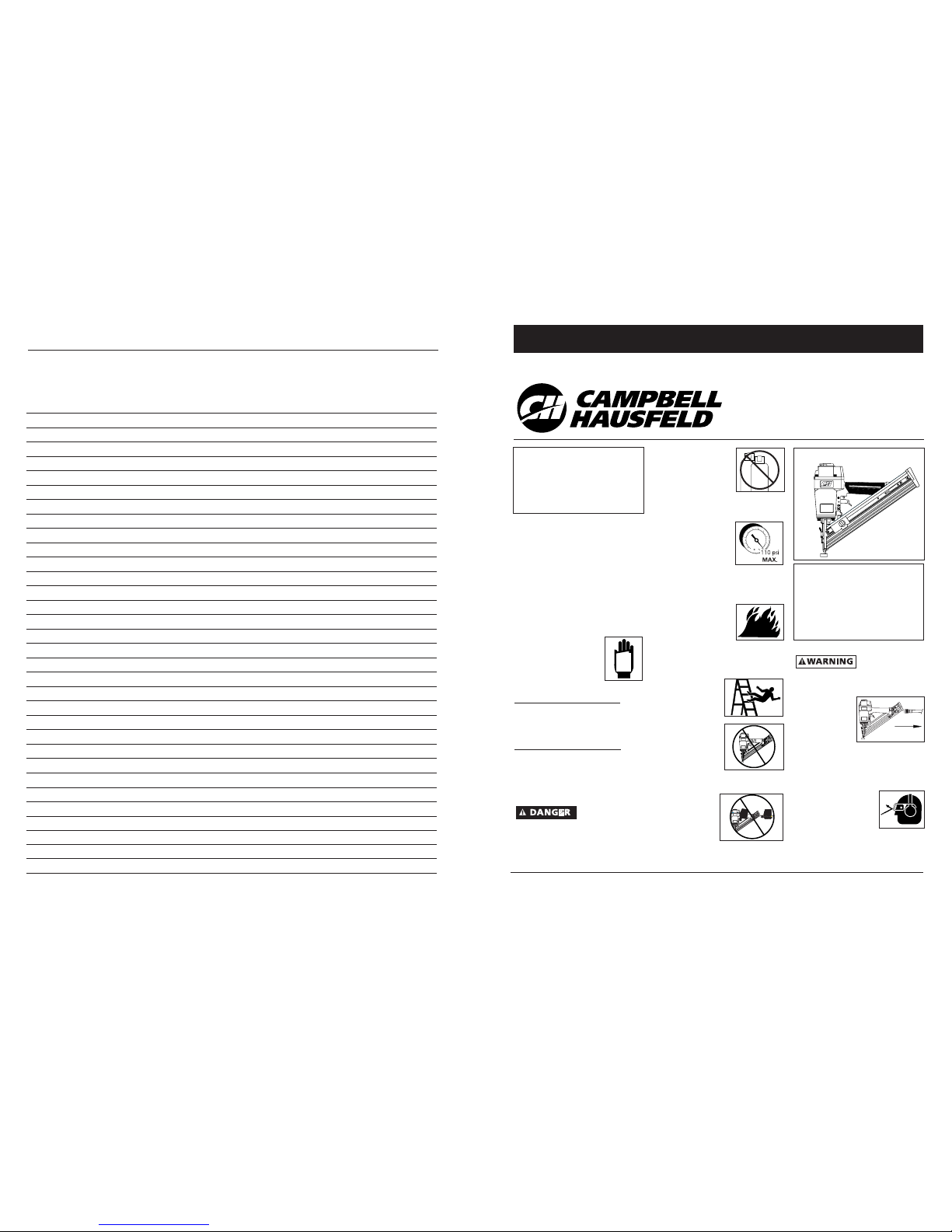
Description
This nailer is designed for decorative
trim, molding, window casings, furniture trim and picture frame assembly.
Features include: convenient rear loading
magazine which holds up to 100 nails,
no-mar tip, adjustable exhaust, single
cycle trigger, quick clear nose, and an
adjustable depth of drive mechanism.
MANUAL
O
CO
2
8-Sp
Modelo NB3565
Notas
Manual de Instrucciones
Page 2
2
● Do not use a
check valve or
any other
fitting which
allows air to
remain in the
nailer. Death or serious personal
injury could occur.
● Never place hands
or any other body
parts in the nail
discharge area of
the nailer. The
nailer might eject
a fastener and could result in death
or serious personal injury.
● Never carry the
nailer by the air
hose or pull the
hose to move the
nailer or a com-
pressor. Keep
hoses away from
heat, oil and sharp edges. Replace
any hose that is damaged, weak or
worn. Personal injury or tool dam-
age could occur.
●
Always assume the nailer contains
nails. Never use the nailer as a toy.
Do not engage in horseplay. Always
keep others at a safe distance from
the work area in case of accidental
discharge of nails. Never point the
nailer at anyone. Accidental trigger-
ing of the nailer could result in
death or serious
personal injury.
●
Do not drive a
nail on top of
other nails. The
nail could glance
and cause death or a serious punc-
ture wound.
● Do not operate
or allow anyone
else to operate
the nailer if any
warnings or
warning labels
are not legible.
Warnings or warning labels are locat-
ed on the nailer magazine and body.
● Never leave the nailer unattended or
connected to an air compressor when
not in use. Serious personal injury
can occur if someone picks up and
uses the nailer without knowing the
correct way to operate the nailer.
● Do not drop or throw the tool.
Dropping or throwing the tool can
result in damage that will make the
tool unusable or unsafe. If the tool
has been dropped or thrown, exam-
ine the tool closely for bent, cracked
or broken parts and air leaks. STOP
and repair before using or serious
injury could occur.
Caution indicates a
potentially haz-
ardous situation which, if not avoided,
MAY result in minor or moderate injury.
● Do not modify or alter the nailer or
any nailer parts. Do not use the nailer
if any shields or guards are removed
or altered. Do not use the nailer as a
hammer. Personal injury or tool
damage may occur.
●
Avoid long extended periods of work
with the nailer. Stop using the nailer
if you feel pain in hands or arms.
● Always check
that the Work
Contact
Element (WCE)
is operating
properly. A nail
could acciden-
tally be driven
if the WCE is
not working properly. Personal
injury may occur (See "Checking the
Work Contact Element" Section).
● Disconnect air supply and release
tension from the pusher before
attempting to clear jams because
fasteners can be ejected from the
front of the nailer. Personal injury
may occur.
Notice indicates
important infor-
mation, that if not followed, MAY
cause damage to equipment.
● Avoid using the nailer when the
magazine is empty. Accelerated
wear on the nailer may occur.
● Clean and check all air supply hoses
and fittings before connecting the
nailer to an air supply. Replace any
damaged or worn hoses or fittings.
Tool performance or durability may
be reduced.
● Air compressors providing air to the
nailer should follow the require-
ments established by the American
National Standards Institute
Standard B19.3-1991; Safety
Standard for Compressors for
Process Industries. Contact your air
compressor manufacturer for
information.
!
NOTICE
Model NB3565
Operating Instructions
!
WARNING
Quick Clear Latch
Rubber No-Mar Tip
Nail Discharge Area
Pin (Single Cycle)
Nail Loading Area
Warning Labels
Magazine
Trigger
Retaining Spring
Nail Pusher
Release Catch
Adjustable Direction
Exhaust Deflector
• REQUIRES: 1.8 SCFM with 10 nails
per minute @ 90 psi
• AIR INLET: 1/4” NPT
• NAIL SIZE RANGE: 1-1/2” to 2-1/2”
• MAGAZINE CAPACITY:
100 Nails per load, 15 or 14 gauge
• WEIGHT: 5 lbs., 6.5 oz.
• LENGTH: 14-1/4”
• HEIGHT: 12”
• MAXIMUM PRESSURE: 110 psi
• PRESSURE RANGE: 70 - 110 psi
Nailer Components And Specifications
7-Sp
Manual de Instrucciones
Modelo NB3565
!
WARNING
Garantía Limitada
1. DURACION: A partir de la fecha de compra por el comprador original tal como se especifica a continuación: Productos
Estándard- Un año, Productos Resistentes-Dos años, Productos Robustos- Tres años
2. QUIEN OTORGA ESTA GARANTIA (EL GARANTE: Campbell Hausfeld / A Scott Fetzer Company, 100 Production Drive,
Harrison, Ohio 45030, Telephone: (800) 543-6400
3. BENEFICIARIO DE ESTA GARANTIA (EL COMPRADOR): El comprador original (que no sea un revendedor) del producto
Campbell Hausfeld.
4. PRODUCTOS CUBIERTOS POR ESTA GARANTIA: Todos los compresores de aire portátiles Campbell Hausfeld, herramien-
tas u accesorios neumáticos suministrados o fabricados por el Garante.
5. COBERTURA DE LA GARANTIA: Los defectos de material y fabricación que ocurran dentro del periodo de validez de la
garantía.
6. LO QUE NO ESTA CUBIERTO POR ESTA GARANTIA:
A. LAS GARANTIAS IMPLICITAS, INCLUYENDO LAS GARANTIAS DE COMERCIALIDAD Y CONVENIENCIA PARA UN FIN PAR-
TICULAR, TAL COMO SE ESPECIFICA EN EL PARRAFO DE DURACION. Si este producto es empleado para uso comercial,
industrial o para renta, la garantía será aplicable por noventa (90) días a partir de la fecha de compra. En algunos
estados no se permiten limitaciones a la duración de las garantías implicitas, por lo tanto, en tal caso esta limitación
no es aplicable.
B. CUALQUIER PERDIDA DAÑO INCIDENTAL, INDIRECTO O CONSECUENTE QUE PUEDA RESULTAR DE UN DEFECTO,
FALLA O MALFUNCIONAMIENTO DEL PRODUCTO CAMBELL HAUSFELD. En algunos estados no se permite la exclusión
o limitación de daños incidentales o consecuentes, por lo tanto, en tal caso esta limitación o exclusión no es aplicable.
C. Cualquier falla que resulte de un accidente, abuso, negligencia o incumplimiento de las instrucciones de fun-
cionamiento y uso indicadas en el (los) manual(es) que se adjunta(n) al producto. Un accidente, abuso, negligencia o
incumplimiento de las instrucciones de funcionamiento y uso también incluirá la remoción o modificación de
cualquiera de los mecanismos de seguridad. Si tales mecanismos de seguridad son removidos o modificados, esta
garantía queda nula.
D. Los ajustes normales explicados en el(los) manual(es) que se adjunta(n) al producto
E. Los artículos o servicio normalmente requeridos para el mantenimiento del producto, tales como juntas tóricas,
resortes, topes, rejilla protectora, expulsador, etc. Estos artículos de desgaste normal se garantizan por un período de
noventa días solamente desda la fecha original de compra.
F. Los artículos o servicios normalmente requeridos para el mantenimiento del producto, tales como lubricantes, filtros y
empaques.
7. RESPONSABILIDADES DEL GARANTE BAJO ESTA GARANTIA: Reparar o reemplazar, como lo decida el Garante, los pro-
ductos o componentes defectuosos dentro del periodo de validez de la garantía.
8. RESPONSABILIDADES DEL COMPRADOR BAJO ESTA GARANTIA:
A. Entregar o enviar el producto o componente Campbell Hausfeld al Centro de Servicio autorizado Campbell Hausfeld
más cercano. Los gastos de flete, de haberlos, deben ser pagados por el comprador.
B. Tener cuidado al utilizar el producto, tal como se indica(n) en el (los) manual(es) del propietario.
9. CUANDO EFFECTUARA EL GARANTE LA REPARACION O REEMPLAZO CUBIERTO BAJO ESTA GARANTIA:
A. La reparación o reemplazo dependerá del flujo normal de trabajo del centro de servicio y de la disponibilidad de
repuestos.
B.
Si el comprador no recibe resultados satisfactorios en el Centro de Servicio a Clientes de Campbell Hausfeld. (Ver Párrafo 2).
Garantía limitada es válida sólo en los Estados Unidos y Canada y le otorga derechos legales específicos. Usted también
podría tener otros derechos que varían de un Estado a otro o de un país a otro.
Impreso en Taiwan
Page 3

3
Operating The Nailer
Read this manual and understand
all safety warnings and instruc-
tions before operating the nailer.
LUBRICATION
This nailer requires lubrication before
using the nailer for the first time and
before each use. If an inline oiler is
used, manual lubrication through the
air inlet is not required on a daily basis.
The work surface
can become dam-
aged by excessive lubrication. Proper
lubrication is the owner’s responsibil-
ity. Failure to lubricate the nailer prop-
erly will dramatically shorten the life
of the nailer and void your warranty.
1. Disconnect the
air supply from
the nailer to
add lubricant.
2. Turn the nailer
so the air inlet
is facing up.
Place 4-5 drops
of 30 W non-
detergent oil into air inlet. Do not
use detergent oils, oil additives, or
air tool oils. Air tool oils contain sol-
vents which will damage the nailer's
internal components.
3. After adding oil,
run nailer briefly.
Wipe off any
excess oil from
the cap exhaust.
!
NOTICE
Operational Modes
The NB3565 finish nailer may be operat-
ed in the “Single Cycle” or the “Bottom
Trip” mode. The
nailer comes deliv-
ered in the single
cycle mode. A pin
when in place in
the nailer allows
you to operate in the single cycle mode.
When the pin is removed, the nailer will
operate in the bottom trip mode.
Always know the
operational mode
of the nailer before using. Failure to
know the operational mode could
result in death or serious personal
injury.
SINGLE CYCLE MODE
This method is recommended when
precise nail placement is required. The
single cycle pin must be installed in the
nailer. This mode requires the trigger to
be pulled each
time a nail is
driven. The nail-
er can be actu-
ated by depress-
ing the WCE
against the work surface followed by
pulling the trigger. Or the nailer can be
actuated by pulling the trigger and
then depressing the WCE against the
work surface.
The trigger must be released to reset the
tool before another nail can be driven.
If the tool is in bottom trip mode
because the single cycle pin has previ-
ously been removed, reinstall the single
cycle pin to convert the tool back to sin-
gle cycle mode.
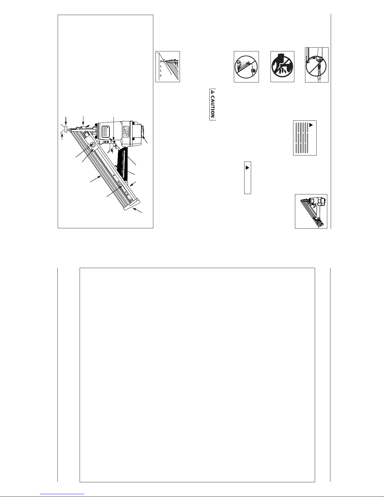
RECOMMENDED HOOKUP
The illustration below shows the
recommended hookup for the nailer.
1. The air com-
pressor must be
able to main-
tain a minimum
of 70 PSI when
the nailer is being used. An inade-
quate air supply can cause a loss of
power and inconsistent
driving.
2. An oiler can be
used to provide oil
circulation through
the nailer. A filter
can be used to
remove liquid and solid impurities
which can rust or “gum up” inter-
nal parts of the nailer.
3. Use 3/8” air
hoses with a
minimum
working pres-
sure of 150 PSI. Use 1/2” air hoses
for 50’ run or longer. For better
performance, install a 3/8” quick
plug (1/4” NPT threads) with an
inside diameter of .315” (8mm) on
the nailer and a 3/8” quick coupler
on the air hose.
4. Use a pressure regulator on the
compressor, with an operating pres-
sure of 0 - 125 PSI. A pressure regu-
lator is required to control the
operating pressure of the nailer
between 70 and 110 PSI.
Model NB3565
Operating Instructions
70 PSI
Min.
Single Cycle Pin
OIL
2
1
110 PSI
Max.
150 PSI WP
3/8” I.D.
Hay una fuga de aire en el
área de la válvula del gatillo
Hay una fuga de aire entre la
cubierta y la boquilla
Hay una fuga de aire entre la
cubierta y la tapa
La clavadora deja de clavar un
clavo
La clavadora funciona lenta-
mente o pierde su potencia
Hay clavos atascados en la
clavadora
Hay una fuga de aire en el
vástago de la válvula del gatillo
Los anillos en O de la cubierta de la válvula del
gatillo están dañados
Los tornillos de la cubierta están flojos
Los anillos en O están dañados
La defensa está dañada
Los tornillos están flojos
El empaque está dañado
La defensa está desgastada
La boquilla está sucia
La suciedad o daños evitan el desplazamiento
libre de los clavos o el mecanismo de impulso
en el cargador
El resorte del mecanismo de impulso está dañado
El flujo de aire hacia la clavadora es inadecuado
El anillo en O del pistón está desgastado o le
falta lubricación
Los anillos en O de la válvula del gatillo están
dañados
Hay fugas de aire
Hay una fuga en el empaque de la tapa
La clavadora no está bien lubricada
El resorte de la tapa del cilindro está roto
El orificio de salida de la tapa está obstruído
La guía del mecanismo de impulso está desgastada
Los clavos no son del tamaño adecuado.
Los clavos están doblados
Los tornillos del cargador o de la boquilla están flojos
El mecanismo de impulso está dañado
Los anillos en O o los sellos están dañados
Debe reemplazar los anillos en O & chequear el fun-
cionamiento del elemento de funcionamiento al contacto
Debe apretar los tornillos
Debe reemplazar los anillos en O
Debe reemplazar la defensa
Debe apretar los tornillos
Debe reemplazar el empaque
Debe reemplazar la defensa
Debe limpiar el canal del sistema de impulso
Debe limpiar el cargador
Debe reemplazar el resorte
Chequée las conexiones, la manguera o el compresor
Debe reemplazar los anillos en O. Lubríquelos.
Debe reemplazar los anillos en O
Debe apretar los tornillos y las conexiones
Debe reemplazar el empaque
Necesita lubricar la clavador
Debe reemplazar el resorte
Debe reemplazar las partes internas dañadas
Debe reemplazar la guía
Debe usar los clavos recomendados para esta clavadora
Reemplácelos con clavos en buenas condiciones
Debe apretar los tornillos
Debe reemplazar el mecanismo de impulse de clavos
Debe reemplazar los anillos en O o los sellos
Guía de Diagnóstico de Averías
Deje de usar la clavadora inmediatamente si alguno de los si guientes problemas ocurre.
repuestos. Podría resultado le heridas graves. Cualquier reparación o reemplazo de piezas los
debe hacer un técnico calificado personal de un centro autorizado de servicio.
!
ADVERTENCIA
Problema Causa Solución
6-Sp
Manual de Instrucciones
Modelo NB3565
Clavos
Estos clavos para acabado de Campbell Hausfeld los puede comprar en su tienda más cercana. Si necesita ayuda para encon-
trar un artículo, comuníquese al 1-800-543-6400. Los clavos de Campbell Hausfeld cumplen o exceden el estándar ASTM F1667
Calibre Clavos por Clavos por
Modelo # Longitud
del cuerpo
Acabado Cabeza Unión
línea Caja
FB354050 3,81 cm 15 Lisa Clavo acabado Cinta pegante mylar 100 4000
FB354550 4,44 cm 15 Lisa Clavo acabado Cinta pegante mylar 100 4000
FB355050 5,08 cm 15 Lisa Clavo acabado Cinta pegante mylar 100 4000
FB356550 6,35 cm 15 Lisa Clavo acabado Cinta pegante mylar 100 4000
FB356540 6,35 cm 14 Lisa Clavo acabado Cinta pegante mylar 100 4000
Información de intercambio
Los clavos usados con la clavadora para acabado NB3565 de Campbell Hausfeld también se pueden usar con las clavado-
ras Sears 18329, Porter Cable DA250, Senco SFN2B, SFN1 y SFN40.
Recommended Hookup
Quick
Plug
Quick
Coupler
Air
Hose
Quick Plug
(Optional)
Quick
Coupler
(Optional)
Oiler
Regulator
Filter
Page 4

BOTTOM TRIP MODE
This method is recommended when less
precise nail place-
ment is required.
The single cycle
pin must be
removed from the
nailer. Remove the
pin by removing the o-ring on one end
and pushing the pin out. Replace the o-
rings on the pin after removing the pin
from the nailer and keep the pin
assembly for later use.
Bottom trip opera-
tion requires the
trigger to be
pulled with the
nailer off the work
surface. Then, the nose of the nailer is
tapped against the work surface caus-
ing a nail to be driven.
Each time the
Work Contact
Element (WCE) is
depressed, a nail is
driven into the
work surface. Care should be taken
when using this method because a nail
will be driven when the WCE is
depressed by any surface.
To convert the tool back to single cycle
operation, reinstall the single cycle pin
and attach an o-ring to each end.
WORK CONTACT ELEMENT (WCE)
Check the opera-
tion of the Work
Contact Element (WCE) trip mecha-
nism before each use. The WCE must
move freely without binding through
its entire travel distance. The WCE
spring must return the WCE to its
fully extended position after being
depressed. Do not operate the nailer
if the WCE trip mechanism is not
operating properly. Personal injury
may occur.
1. Disconnect the
air supply from
the nailer.
LOADING THE NAILER
1. Always connect the tool to the air
supply before loading fasteners.
2. Pull nail pusher
mechanism back
until pusher
drops into slot
on magazine.
3. Insert one stick
of nails into rear
loading slot
while holding
tool down so
nails will slide
forward in mag-
azine. NOTE:
Make certain to
insert nail heads
into wide area
at top of magazines with nail points
down.
4. Push release tab on pusher mecha-
nism to disengage from slot. Allow
pusher to rest against nails. The
nailer is now loaded.
UNLOADING THE NAILER
1. Always unload all fasteners before
removing tool from service.
Unloading is the reverse of load-
ing, except always disconnect the
air hose before unloading.
2. Pull nail pusher
mechanism back
until pusher
drops into slot
on magazine.
3. Hold tool
upright so nails
will slide out of
magazine.
4. Push release tab
on pusher mech-
anism to disen-
gage from slot
and hold mech-
anism while sliding to front of mag-
azine.
2. Remove all nails
from the maga-
zine (see
Loading/
Unloading).
3.
Make sure the
trigger and work
contact element
(WCE) move
freely up and
down without sticking or binding.
4. Reconnect air
supply to the
nailer.
5. Depress the
Work Contact
Element (WCE)
against the
work surface
without pulling
the trigger. The nailer MUST NOT
OPERATE. Do not use the tool if it
operates without pulling the trig-
ger. Personal injury may result.
6. Remove the
nailer from the
work surface.
The Work
Contact
Element (WCE)
must return to its original down
position. The nailer MUST NOT
OPERATE. Do not use the tool if it
operates while lifted from the work
surface. Personal injury may result.
7. Pull the trig-
ger and
depress the
work contact
element
(WCE)
against the work surface. The nailer
MUST OPERATE.
8. Depress the
Work
Contact
Element
(WCE)
against the
work surface. Pull the trigger. The
nailer MUST OPERATE.
Model NB3565
Operating Instructions
4
2
1
1
2
Pin Out
CÓMO AJUSTAR LA PENETRACIÓN
DEL CLAVO
La NB3565 viene equipada con un
mecanismo clavador de profundidad
ajustable. Esto le permite al usuario
determinar a qué profundidad se va a
clavar en la superficie de trabajo.
1. Ajuste la presión de operación a
aquélla que usará con regularidad
para clavar los sujetadores. No exce-
da la presión de operación máxima
de la clavadora de 110 psi.
2.
A fin de
aumentar
la profun-
didad a la
cual se va
a clavar,
rote la
rueda a la
izquierda (en el sentido contrario a las
manillas del reloj). Para disminuir la
profundidad, rote la rueda a la
derecha (en el sentido de las manillas
del reloj). Los retenes cargados a
resorte sujetan la rueda en su lugar
después de cada ajuste.
3. Asegúrese que el
gatillo y el Elemento
de Contacto de
Trabajo se mueven
libremente hacia arri-
ba y hacia abajo sin
atascarse o pegarse después de cada
ajuste.
PARA AJUSTAR LA DIRECCION DEL
TUBO DE ESCAPE
La clavadora
NB3565 está
equipada con un
deflector ajustable
de la dirección del
tubo de escape.
Éste le permite al usuario cambiar la
dirección del tubo de escape.
Simplemente mueva el deflector hacia
la dirección deseada.
QUE HACER CUANDO LA CLAVADO-
RA TENGA UN CLAVO ATASCADO
1. Desconecte la
clavadora de la
fuente de sum-
inistro de aire.
2. Remueva todos
los clavos del
depósito (vea
Carga /
Descarga). De
lo contrario, los
clavos serán expulsados de la parte
delantera de la herramienta.
3. Abra el pestillo
tirándolo hacia
afuera y abajo.
El pestillo de
alambre se sal-
drá de los gan-
chos en la boquilla.
4. Ahora se
puede rotar la
puerta, dejan-
do el sujetador
atascado
expuesto.
5. Saque el clavo
atascado con
un alicate o
destornillador,
si es necesario.
6
Rote la puerta
hacia atrás a la
posición cerrada.
7. Extienda el
pestillo de
alambre y
colóquelo
sobre los gan-
chos de la
boquilla.
8. Cierre el pestil-
lo empujándo-
lo hacia aden-
tro hasta que
ajuste en su
posición.
9. Asegúrese que
el gatillo y el
Elemento de
Contacto de
Trabajo se
mueven libre-
mente, hacia arriba y hacia abajo
sin pegarse o atascarse.
Servicio Técnico
Si desea hacer alguna pregunta refer-
ente a la reparación u operación de las
clavadoras, sírvase llamar a nuestro
número especial, 1-800-543-6400. Si
llama desde Ohio o fuera de los
Estados Unidos continentales,
comuníquese con nosotros al
1-513-3678-1182.
Clavos et Repuestos
Use sola-
mente
sujetadores Campbell Hausfeld origi-
nales calibre 15 (o su equivalente) -
(vea la información sobre intercam-
bio de sujetadores). Use solamente
partes de repuesto Campbell
Hausfeld originales. Nunca substituya
las partes. No use partes modificadas
o partes que no den un rendimiento
equivalente al equipo original. El
rendimiento de las herramientas, la
seguridad y la duración pueden verse
reducidos. Cuando ordene partes de
repuesto o sujetadores, especifique
el número de la parte.
Para reparar la clavadora
Las reparaciones de la clavadora las
debe hacer SOLAMENTE un técnico cal-
ificado que tenga experiencia.
Para colocarle los sellos
Cada vez que repare una clavadora
deberá limpiarle y lubricarle las partes
internas. Le recomendamos que use
Parker O-lube o un lubricante equiva-
lente en todos los anillos en O. A cada
anillo en O se le debe dar un baño de
lubricante para anillos antes de insta-
larlos. Igualmente, deberá ponerle un
poco de aceite a todas las piezas que se
mueven y muñones. Finalmente,
después de haberla ensamblado y antes
de probar la herramienta deberá pon-
erle unas cuantas gotas de aceite sin
detergente 30W u otro aceite similar,
en las líneas de aire.
Modelo NB3565
5-Sp
Manual de Instrucciones
Rotate
Gire
Movement
!
ADVERTENCIA
COUNTER-
CLOCKWISE
CLOCKWISE
en el sentido
contrario a
las manillas
del reloj
en el sentido de
las manillas
del reloj
movemiento
movemiento
Movement
Nail Pusher
Mechanism
Release
tab
Nail Pusher
Mechanism
Slot
Page 5

ADJUSTING THE NAIL PENETRATION
The NB3565 is equipped with an adjustable
depth of drive feature. This allows the user
to determine how deep a fastener will be
driven into the work surface.
1. Adjust the operating pressure to a
pressure which will consistently
drive the fasteners. Do not exceed
the maximum operating pressure of
the nailer of 110 psi.
2.
To increase
depth of
drive, rotate
thumbwheel
to the left
(counter-
clockwise). To decrease depth of
drive, rotate thumbwheel to the
right (clockwise). Spring loaded
detents hold the thumbwheel in
place after each adjustment.
3. Make sure that the
trigger and work con-
tact element (WCE)
move freely up and
down without bind-
ing or sticking after
each adjustment.
ADJUSTING THE DIRECTION OF THE
EXHAUST
The NB3565 is
equipped with an
adjustable direc-
tion exhaust
deflector. This is
intended to allow the user to change
the direction of the exhaust. Simply
twist the deflector to any direction
desired.
CLEARING A JAM FROM THE NAILER
1. Disconnect the
air supply from
the nailer.
2. Remove all
nails from the
magazine (see
Loading/
Unloading).
Failure to do so will cause the nails
to eject from the front of the tool.
3. Undo latch by
pulling out and
down. The wire
latch will disen-
gage from the
hooks on the nose.
4. The door can
now be rotat-
ed, exposing
the jammed
fastener.
5. Remove the
jammed fasten-
er, using pliers
or a screwdriv-
er if required.
6 Rotate door
back into the
closed position.
7. Extend the
wire latch and
place over the
hooks on the
nose.
8. Close the latch
by pushing the
latch up and in
until the latch
snaps into
place.
9.
Make sure the
trigger and
work contact
element (WCE)
move freely up
and down with-
out sticking or binding.
Technical Support
Please call our Nailer Hotline at 1-800-
543-6400 with any questions regarding
the operation or repair of this nailer.
If calling from Ohio or outside of the
continental United States, please call,
1-513-367-1182.
Fastener And Replacement
Parts
Use only
genuine Campbell
Hausfeld 15 gauge fasteners (or
equivalent - see Fastener Interchange
Information). Use only genuine
Campbell Hausfeld replacement
parts. Never substitute parts. Do not
use modified parts or parts which
will not give equivalent performance
to the original equipment. Tool per-
formance, safety and durability could
be reduced. When ordering replace-
ment parts or fasteners, specify by
part number.
Nailer Repair
Nailer repairs must be performed by
qualified and experienced service
people ONLY.
Assembly Procedure For
Seals
When repairing a nailer, the internal
parts must be cleaned and lubricated.
Parker O-lube or equivalent must be
used on all o-rings. Each o-ring must be
coated with O-lube before assembling.
A small amount of oil must be used on
all moving surfaces and pivots. After
reassembling, a few drops of 30W non-
detergent oil or equivalent, must be
added through the air line before
testing.
Model NB3565
Operating Instructions
5
Movement
Rotate
ACTIVACION DE LA PARTE INFERIOR
Este método es
recomendable
cuando necesite
clavar con menos
presición. Deberá
sacarle el pasador
a la clavadora. Para sacarle el pasador,
sáquele el anillo en O en uno de los
extremos y empuje el pasador hacia
afuera. Colóquele los anillos en O al
pasador y guárdelos juntos para usarlos
posteriormente.
Para clavar con el
sistema de acti-
vación de la parte
inferior, debe
oprimir el gatillo
sin que la clavado-
ra esté en contacto con la superficie
donde vaya a clavar. Después, la
boquilla de la clavadora debe hacer
contacto con la superficie para que la
clavadora dispare el clavo.
Cada vez que el
elemento de con-
tacto se activa, la
clavadora dis-
parará un clavo.
Debe tener mucho
cuidado cuando esté clavando de esta
manera ya que la clavadora disparará
un clavo inmediatamente que el ele-
mento de contacto toque cualquier
superficie.
Para volver a usar la herramienta en el
ciclo sencillo, deberá colocarle el
pasador a la clavadora y un anillo en O
en cada extremo.
ELEMENTO DE CONTACTO
Chequée
el fun-
cionamiento del mecanismo del ele-
mento de contacto antes de cada uso.
El elemento de contacto se debe
desplazar libremente, sin pegarse, a lo
largo del área de desplazamiento. El
resorte del elemento de contacto debe
regresar el elemento de contacto a su
posición original totalmente extendido.
No use la clavadora si el mecanismo del
elemento de contacto no está funcio-
nando adecudamente. Podría ocasion-
arle heridas.
1. Desconecte la
clavadora de la
fuente de sum-
inistro de aire.
!
PRECAUCION
PARA CARGAR LA CLAVADORA
1. Siempre conecte la herramienta a la
fuente de suministro de aire antes de
cargarla.
2. Tire hacia atrás el
mecanismo impul-
sor de clavos hasta
que el impulsor
haya calzado en la
ranura del car-
gador.
3. Introduzca una
serie de clavos a
través del orificio
posterior mien-
tras sostiene la
herramienta
hacia abajo de
modo que los
clavos se deslicen
hacia adelante
en el cargador.
NOTA: Cerciórese de introducir la
cabeza del clavo en la parte ancha
superior con la punta hacia abajo.
4. Oprima la lengüeta del mecanismo
impulsor para desconectar el mecan-
ismo de la ranura. El impulsor debe
hacer contacto con los clavos. Ahora
la clavadora está cargada.
PARA DESCARGAR LA CLAVADORA
1. Siempre sáquele todos los clavos a la
clavadora antes de guardarla al termi-
nar de usarla. Para descargar la
unidad debe hacer lo contrario que se
hace para cargarla, excepto que siem-
pre debe desconectar la manguera
de aire antes de comenzar a descargar
la unidad.
2. Tire hacia atrás el
mecanismo impul-
sor de clavos hasta
que el impulsor
haya calzado en la
ranura del car-
gador.
3. Sostenga la her-
ramienta hacia
arriba de modo
que los clavos sal-
gan del cargador.
4. Oprima la
lengüeta del
mecanismo
impulsor para
desconectar el
mecanismo de la
ranura y empújelo hacia adelante.
2. Saque todos
los clavos del
cargador (Vea
la Sección
Carga-
Descarga).
3. Cerciórese de
que el gatillo y
el elemento de
contacto se
muevan libre-
mente en ambos sentidos sin atas-
carse o pegarse.
4.
Reconecte la
clavadora a la
fuente de sum-
inistro de aire.
5.
Presione el
Elemento de
Contacto de
Trabajo contra
la superficie de
trabajo sin apretar el gatillo. La
clavadora NO DEBE OPERAR. No use
la herramienta si opera sin apretar el
gatillo. Se pueden producir lesiones
personales.
6. Remueva la
clavadora de la
superficie de
trabajo. El
Elemento de
Contacto de
Trabajo tiene que volver a su posi-
ción original. La clavadora NO
DEBE OPERAR. No use la her-
ramienta si opera mientras está lev-
antada de la superficie de trabajo.
7. Apriete el
gatillo y pre-
sione el
Elemento de
Contacto de
Trabajo contra la superficie de tra-
bajo. La clavadora DEBE OPERAR.
8. Presione el
Elemento de
Contacto de
Trabajo con-
tra la super-
ficie de trabajo. Apriete el gatillo.
La clavadora DEBE OPERAR.
Modelo NB3565
Manual de Instrucciones
4-Sp
2
1
Pin Out
Clavija Fuera
Movimiento
1
2
COUNTER-
CLOCKWISE
CLOCKWISE
Movement
Nail Pusher
Mechanism
Lengüeta
Mecanismo
impulsor
del clavo
Ranura
Mecanismo
impulsor
del clavo
Page 6

cillo. Para operar de esta manera la
clavadora necesita que se le coloque un
pasador. Si le quita dicho pasador, la
clavadora funcionará sólo con el sis-
tema de activación de la parte inferior.
Siempre
cer-
ciórese de saber en que modo va a
operar la clavadora antes de comen-
zar a usarla. De lo contrario, le
podría ocasionar la muerte o heridas
graves.
CICLO SENCILLO
Este método es recomendado cuando
necesite clavar con precisión. Le debe
instalar a la clavadora el pasador para
ciclo sencillo.
Este sistema
requiere que
oprima el gatillo
cada vez que
vaya a clavar un
clavo. Para clavar el elemento de con-
tacto debe tocar la superficie de traba-
jo y el operador debe oprimir el gatil-
lo. Igualmente, puede oprimir el gatillo
primero y después hacer el contacto.
Debe soltar el gatillo antes de clavar
otro clavo.
Si la herramienta está en el ciclo de
activación de la parte inferior, porque
le han desconectado el pasador,
colóquele el pasador para usarla del
modo de ciclo sencillo.
!
ADVERTENCIA
6
Model NB3565
Operating Instructions
Air leaking at trigger valve
Air leaking between housing
and nose
Air leaking between housing
and cap
Nailer skips driving nail
Nailer runs slow or has loss of
power
Nails are jammed in nailer
Air leaking at trigger valve
stem
O-Rings in trigger valve housing are dam-
aged
Loose screws in housing
Damaged O-Rings
Damage to bumper
Loose screws
Damaged gasket
Worn bumper
Dirt in nose piece
Dirt or damage prevent nails or pusher from
moving freely in magazine
Damaged pusher spring
Inadequate air flow to nailer
Worn O-Ring on piston or lack of lubrication
Damaged O-Ring on trigger valve
Air leaks
Cap gasket leaking
Nailer not lubricated sufficiently
Broken spring in cylinder cap
Exhaust port in cap is blocked
Guide on driver is worn
Nails are not correct size
Nails are bent
Magazine or nose screws are loose
Driver is damaged
O-Rings or seals are damaged
Replace O-Rings. Check operation of Work Contact
Element (WCE)
Tighten screws
Replace O-Rings
Replace bumper
Tighten screws
Replace gasket
Replace bumper
Clean drive channel
Clean magazine
Replace spring
Check fitting, hose or compressor
Replace and lubricate O-Rings
Replace O-Rings
Tighten screws and fittings
Replace gasket
Lubricate nailer
Replace spring
Replace damaged internal parts
Replace guide
Use only recommended nails
Replace with undamaged nails
Tighten screws
Replace driver
Replace O-Rings or seals
Troubleshooting Guide
Stop using nailer immediately if any of the following problems occur. Serious
personal injury could result. Any repairs or replacements must be done by a
Qualified Service Person or Authorized Service Center.
Problem Cause Solution
Fasteners
The following Campbell Hausfeld finishing nails are available at local retail stores. If you need help locating any item,
call customer service at 1-800-543-6400. Campbell Hausfeld nails meet or exceed ASTM Standard F1667.
Shank Nails Per Nails Per
Model # Length
Gauge
Finish Head Collation
Stick Box
FB354050 1-1/2” 15 Gauge Smooth Finish Brad Mylar tape 100 4000
FB354550 1-3/4” 15 Gauge Smooth Finish Brad Mylar tape 100 4000
FB355050 2” 15 Gauge Smooth Finish Brad Mylar tape 100 4000
FB356550 2-1/2” 15 Gauge Smooth Finish Brad Mylar tape 100 4000
FB356540 2-1/2" 14Gauge Smooth Finish Brad Mylar tape 100 4000
Interchange Information
Nails used in the Campbell Hausfeld NB3565 Angle Finish Nailer will also work in Sears 18329, Porter Cable DA250, Senco
SFN2B, SFN1 and SFN40.
Cómo usar la clavadora
Lea este manual y comprenda todas
las medidas de seguridad e instruc-
ciones antes de utilizar la clavadora.
LUBRICACION
Esta clavadora requiere lubricación
antes de usarse por primera vez y antes
de cada uso. Si utiliza un lubricador
incorporado a la línea, no tendrá que
lubricarla manualmente a diario.
La super
ficie de
trabajo se podría dañar debido a la
lubricación excesiva. La lubricación
adecuada es la responsabilidad del
propietario. Si no lubrica la clavadora
adecuadamente, ésta se dañará rápida-
mente y la garantía se cancelaría.
1. Desconecte la
clavadora de la
fuente de sum-
inistro de aire
para lubricarla.
2. Gire la clavadora de
modo que la entrada
de aire quede miran-
do hacia arriba.
Agregue de 4 a 5
gotas de aceite no
detergente 30W en la entrada de
aire. No use aceites detergentes,
aditivos de aceite, ni aceites para
herramientas neumáticas. Los
aceites para herramientas neumáti-
cas contienen solventes que pueden
averiar los componentes internos de
la clavadora.
3. Después de agre-
gar aceite, haga
funcionar la
clavadora breve-
mente. Limpie
todo exceso de
aceite que salga
del escape de la tapa.
!
AVISO
Modos de Operación
La clavadora para acabado NB3565 se
puede operar de dos modos: “Ciclo
CONEXION RECOMENDADA
La ilustración de abajo le muestra la
conexión recomendada para la
clavadora.
1.
El compresor
de aire debe
tener la capaci-
dad de suminis-
trar un mínimo
de 4,83 bar
cuando la clavadora esté en uso. Si
el suministro de aire es inadecuado
podría haber pérdida de potencia y
falta de consistencia en el fun-
cionamiento.
2. Puede utilizar un
lubricador para
lubricar la clavado-
ra. Igualmente,
puede utilizar un
filtro para remover
las impurezas líquidas y sólidas que
podrían oxidar u obstruir las partes
internas de la clavadora.
3. Use
mangueras
de aire de
9,5 mm dis-
eñadas para
presiones mínimas de trabajo de
150 psi. Use mangueras de aire de
12,7 mm si la longitud de las mis-
mas es de 50’ ó más. Para un mejor
rendimiento, instalele a la clavado-
ra un conector rápido de 9,5 mm
(con roscas de 6,4 mm NPT) cuyo
diámetro interno sea de 0,315"
(8mm) y un acoplador rápido de 9,5
mm a la manguera de aire.
4. Use un regulador de presión (de 0-
8,62 bar) en el compresor. Se necesi-
ta un regulador de presión para
controlar la presión de operación
de la clavadora entre 4,83 y 7,58
bar.
3-Sp
Modelo NB3565
Manual de Instrucciones
Conexión Recomendada
Regulador
Filtro
Lubricador
Acoplador
rápido
(Opcional)
Manguera de
aire
Conector
rápido
(Opcional)
Acoplador
rápido
Conector
rápido
OIL
4,83 bar
Min.
7,58 bar
Max.
150 PSI WP
9,5 mm I.D.
2
1
aceite
Single Cycle Pin
pasador para
clavado sencillo
Sencillo” o
“Activación de la
parte inferior” . La
clavadora viene de
fábrica lista para fun-
cionar en el ciclo sen-
Page 7

Model NB3565
7
Operating Instructions
● No use una
válvula de
chequeo o
ninguna conex-
ión que permita
que el aire per-
manezca en la
clavadora. Se puede producir la
muerte o lesiones personales graves.
●
Nunca ponga las
manos ni ninguna
otra parte del cuer-
po en el área de
descarga de la
clavadora. Ésta
puede expulsar un
sujetador y producir
la muerte o lesiones personales graves.
●
Nunca cargue la
clavadora por la
manguera de aire
ni hale la manguera
para mover la
clavadora o el com-
presor de aire.
Mantenga las mangueras alejadas del
calor, aceite y objetos puntiagudos.
Reemplace cualquier manguera que
esté dañada, débil o desgastada. Ésto
podría ocasionar heridas o daños a la
herramienta
●
Siempre asuma que la clavadora está
cargada. Nunca la use como juguete.
Siempre mantenga a otros a una dis-
tancia segura en caso de que la
clavadora se dispare accidentalmente.
Nunca la apunte hacia personas. Si la
dispara accidentalmente podría oca-
sionarle la muerte o heridas graves.
● No clave un clavo
encima de otro. El
clavo podría
saltar y ocasion-
arle la muerte o
heridas graves.
2-Sp
● No opere la
clavadora ni per-
mita que otros la
operen si las eti-
quetas de adver-
tencia están ileg-
ibles. Éstas se
encuentran en el cargador o el cuerpo
de la clavadora.
● Nunca deje la clavadora desatendida
o conectada al compresor de aire si
no la va a usar. Si alguien sin experi-
encia comienza a usarla podría oca-
sionarle heridas graves.
● No deje que la herramienta se caiga
ni la tire. Ésto podría dañarla o con-
vertirla en algo peligroso de usar. En
caso de que la herramienta se haya
caido o la hayan tirado, revísela con
cuidado a ver si está doblada o rota,
si tiene alguna pieza dañada o tiene
fugas de aire. DEJE de trabajar y
repárela antes de usarla o podría
ocasionarle heridas graves.
Ésto le
indica
que hay una situación que PODRIA oca-
sionarle heridas no muy graves.
● No modifique o altere la clavadora o
ninguna de sus partes. No use la
clavadora si le faltan alguna de las
tapas protectoras o si éstas han sido
modificadas. No use la clavadora
como un martillo. Se pueden producir
lesiones personales o daños a la her-
ramienta.
● Evite trabajar con esta clavadora por
largos periodos. Deje de usar la
clavadora si siente dolor en las
manos o en los brazos.
!
PRECAUCION
●
Siempre revise
que el Elemento
de Contacto de
Trabajo esté
funcionando
correctamente.
Puede que se
clave un clavo por accidente si el
Elemento de Contacto de Trabajo no
está funcionando correctamente. Se
pueden producir lesiones personales
(vea la sección “Cómo Revisar el
Elemento de Contacto de Trabajo”).
●
Desconecte la fuente de suministro de
aire y elimine la tensión del disparador
antes de tratar de sacar cualquier clavo
atascado, ya que la clavadora podría
disparar un clavopor el frente. Ésto
podría ocasio-narle heridas.
Ésto le indica una
información impor-
tante, que de no seguirla, le PODRÍA oca-
sionar daños al equipo.
● Evite usar la clavadora cuando el
depósito está vacío. Ésto podría acel-
erar su desgasto.
● Limpie y chequée todas las
mangueras de suministro de aire y
conexiones antes de conectar la
clavadora al compresor. Reemplace
las mangueras y conexiones que
estén dañadas o desgastadas. El
rendimiento de la herramienta o su
durabilidad podrían reducirse.
●
Los compresores de aire usados para
suministrarle aire a la clavadora deben
cumplir los requerimientos estableci-
dos por la organización norteameri-
cana ANSI en el código B19.3-1981;
sobre seguridad y estándards para
compresores de aire industriales.
Contacte al fabricante de su compre-
sor de aire para mayor información.
Modelo NB3565
Manual de Instrucciones
Pestillo del
mecanismo de
despeje rápido
Punta de goma
(no deja marcas)
Resorte retenedor
Área de descarga
Pasador (Ciclo
Sensillo)
Gatillo
Area de carga
de los clavos
Cargador
Disparador
de clavos
Pestillo para abrir
Deflector Ajustable de la
Dirección del Tubo de Escape
• REQUIRE: 0,05 m
3
/min para clavar 10
clavos por minuto a 6,21 bar
• ENTRADA DE AIRE: 6,4 mm NPT
• RANGO DE LOS CLAVOS: 3,81 cm
a 6,35 cm
• CAPACIDAD DEL CARGADOR:
100 clavos por carga, calibre 15 o 14
• PESO: 2,27 kg, 184,3 g
• LONGITUD: 36,19 cm
• ALTURA: 30,48 cm
• PRESION MAXIMA: 7,58 bar
• RANGO DE LA PRESION: 4,83 -7,58
bar
Componentes y
Especificaciones de la
Clavadora
Etiquetas de advertencia
!
WARNING
!
ADVERTENCIA
Limited Warranty
1. DURATION: From the date of purchase by the original purchaser as follows: Standard Duty Products - One Year, Serious
Duty Products - Two Years, Extreme Duty Products - Three Years.
2. WHO GIVES THIS WARRANTY (WARRANTOR):
The Campbell Group/ A Scott Fetzer Company, 100 Production Drive, Harrison, Ohio, 45030, Telephone: (800) 543-6400.
3. WHO RECEIVES THIS WARRANTY (PURCHASER): The original purchaser (other than for purposes of resale) of the
Campbell Hausfeld product.
4. WHAT PRODUCTS ARE COVERED BY THIS WARRANTY: Any Campbell Hausfeld nailer.
5. WHAT IS COVERED UNDER THIS WARRANTY: Defects on material and workmanship which occur within the duration of
the warranty period.
6. WHAT IS NOT COVERED UNDER THIS WARRANTY:
A.Implied warranties, including those of merchantability and FITNESS FOR A PARTICULAR PURPOSE ARE LIMITED FROM
THE DATE OF ORIGINAL PURCHASE AS STATED IN THE DURATION. If this product is used for commercial, industrial or
rental purposes, the warranty will apply for ninety (90) days from the date of purchase. Some States do not allow limi-
tation on how long an implied warranty lasts, so the above limitations may not apply to you.
B.ANY INCIDENTAL, INDIRECT, OR CONSEQUENTIAL LOSS, DAMAGE, OR EXPENSE THAT MAY RESULT FROM ANY DEFECT,
FAILURE, OR MALFUNCTION OF THE CAMPBELL HAUSFELD PRODUCT. Some States do not allow the exclusion or limita-
tion of incidental or consequential damages, so the above limitation or exclusion may not apply to you.
C.Any failure that results from an accident, purchaser’s abuse, neglect or failure to operate products in accordance with
instructions provided in the owner’s manual(s) supplied with product. Accident, purchaser’s abuse, neglect or failure to
operate products in accordance with instructions shall also include the removal or alteration of any safety devices. If
such safety devices are removed or altered, this warranty is void.
D.Normal adjustments which are explained in the owner’s manual(s) provided with the product.
E. Items or service that are normally required to maintain the product, i.e. o-rings, springs, bumpers, debris shield, driver,
etc. These said normal wear items will be covered only for ninety days from the date of original purchase.
F. Items or service that are normally required to maintain the product, i.e. lubricants, filters and gaskets, etc.
7. RESPONSIBILITIES OF WARRANTOR UNDER THIS WARRANTY: Repair or replace, at Warrantor’s option, products or com-
ponents which are defective, have malfunctioned and/or failed to conform within duration of the warranty period.
8. RESPONSIBILITIES OF PURCHASER UNDER THIS WARRANTY:
A.Deliver or ship the Campbell Hausfeld product or component to the nearest Campbell Hausfeld Authorized Service
Center. Freight costs, if any, must be borne by the purchaser.
B.Use reasonable care in the operation and maintenance of the products as described in the owner’s manual(s).
9. WHEN WARRANTOR WILL PERFORM REPAIR OR REPLACEMENT UNDER THIS WARRANTY:
A.Repair or replacement will be scheduled and serviced according to the normal work flow at the servicing location, and
depending on the availability of replacement parts.
B.If the purchaser does not receive satisfactory results from the Authorized Service Center, the purchaser should contact
the Campbell Hausfeld Product Service Department (see paragraph 2).
Limited warranty applies in the U.S. and Canada only and gives you specific legal rights. You may also have other rights
which vary from state to state or country to country.
!
AVISO
Printed in Taiwan
Page 8

Operating Instructions
NB3565
Notes
8
Informaciones Generales de
Seguridad
Este manual contiene información sobre
seguridad, funcionamiento y manteimiento.
Lea este manual y cerciórese
de que comprende todas las
medidas de seguridad e
instrucciones antes de usar la
clavadora. Comuníquese con
un representante de
Campbell Hausfeld si tiene alguna pregunta.
RESPONSABILIDAD DEL OPERADOR:
Antes de operar la clavadora, lea y
asegúrese que comprende todas las
advertencias de seguridad y las etiquetas. Siga las instrucciones de operación
descritas en este manual.
RESPONSABILIDAD DEL EMPLEADOR:
Distribuya este manual de instrucciones
a todos los usuarios antes de permitirles usar la clavadora. Asegúrese que
todos los operadores lean, comprendan
y sigan todas las advertencias de
seguridad, las etiquetas y las instrucciones descritas en este manual.
Ésto le indica que hay una situación
inmediata que LE OCASIONARIA la
muerte o heridas de gravedad.
!
PELIGRO
●
No use ningún tipo de
gases inflamables u
oxigeno para operar la
clavadora. Use sólo aire
comprimido filtrado,
lubricado y regulado.
Si
se usa gas comprimido
en vez de aire comprimido, la clavadora podría explotar y producir la
muerte o lesiones personales graves.
●
No exceda la presión
máxima de trabajo de la
clavadora (110 psi) ya
que ésta no funcionará
adecuadamente. No use
una fuente de aire comprimido que pueda suministrar más de 200 psi. La clavadora
podría explotar y producir la muerte o
lesiones personales graves.
● Nunca limpie la
clavadora con gasolina
o ningún otro líquido
inflamable. Nunca use
la clavadora en la cercanías de líquidos o
gases inflamables. Una chispa podría
encender los vapores y ocasionar una
explosión que podría ocasionarle la
muerte o heridas graves.
● Siempre colóquese
en una posición
firme y balanceada
para usar o manipular la clavadora.
●
No modifique ni
deshabilite el
Elemento de
Contacto de Trabajo.
No amarre ni pegue
con cinta adhesiva el
Elemento de
Contacto de Trabajo ni el gatillo en una
posición oprimida. Se puede producir la
muerte o lesiones personales graves.
●
No toque el gatillo a
menos que se estén
clavando clavos.
Nunca haga arrancar
la línea de aire con
una clavadora ni
mueva la clavadora
cuando esté tocando el gatillo. La herramienta podría expulsar un sujetador y
producir la muerte o lesiones personales graves.
Manual de Instrucciones Modelo NB3565
Localice el número del modelo y el número de
serie en la herramienta, el depósito y la tapa, y
regístrelo a continuación:
Modelo No ______________________
Número de Serie ___________________
Conserve estos números
para referencia .
Ésto le
indica
que hay una situación que PODRIA ocasionarle la muerte o heridas graves.
●
Siempre
desconecte la
clavadora de la
tubería de aire
antes de despejar atascamientos, ajustar o dar servicio a la
clavadora, cuando se vuelva a cargar,
o cuando no se está usando. Siempre
vuelva a conectar la tubería de aire
ANTES de cargar los sujetadores. La
clavadora puede expulsar un sujetador y producir la muerte o lesiones
personales graves.
●
Protéjase la vista y los
oídos. Use anteojos de
seguridad Z87, con protección lateral y tápese
los oidos adecuadamente. Los patrones y los usuarios son
responsables de que tanto los opeerarios como otras personas en los alrededores se protegan adecuadamente. De
lo contrario podrían sufrir heridas oculares o sordera permanente shields.
!
ADVERTENCIA
BUILT TO LAST
TM
Clavadora Angular
para Acabado
Modelo NB3565
Sírvase leer y guardar estas instrucciones.Lea con cuidado antes de tratar de armar, instalar, manejar o darle servicio al producto descrito en
este manual. Protéjase Ud. y a los demás observando todas las reglas de seguridad. El no seguir las instrucciones podría resultar en heridas y/o
daños a su propiedad. Guarde este manual como referencia.
IN246201AV 4/98
Las clavadoras de Campbell Hausfeld Nailers cumplen o exceden los estándards de la Industria
establecidos en los códigos SNT-101-1993 de las organizaciones norteamericanas ANSI/ISANTA .
© 1998 Campbell Hausfeld.
Descripción
Esta clavadora está diseñada para trabajos de acabado, moldes interiores, bases,
paneles y ensamblaje e instalación de
gabinetes.
Entre las características se
incluyen: conveniente depósito que se
carga port la parte posterior y sujeta
hasta 100 clavos, punta que no se estropea, escape ajustable, gatillo de ciclo
único, boca de depeja rápido, y profundidad ajustable del mecanismo accionador.
Índice
Info. Generales de Seguridad . . . . .1-2
Especificaciones . . . . . . . . . . . . . . . . . .2
Modos de funcionamiento . . . . . . . . .3
Funcionamiento de la clavadora . . .3-5
Diagnóstico de averías . . . . . . . . . . . .6
Garantía . . . . . . . . . . . . . . . . . . . . . . . .7
MANUAL
O
CO
2
7,58 bar
Max.
Page 9

l’air comprimé filtré, lubrifié et réglé.
L’utilisation d’un gaz comprimé au
lieu de l’air comprimé peut faire
exploser la cloueuse et entraîner des
blessures graves ou mortelles.
● Ne pas dépasser la
pression de service
maximale de la
cloueuse (758 kPa). La
cloueuse ne fonctionnera pas correctement. Ne pas utiliser
une source d’air comprimé qui a une
capacité de plus que 1379 kPa. La
cloueuse pourrait exploser et causer
des blessures graves ou mortelles.
● Ne jamais utiliser de
l’essence ni les fluides
inflammables pour le
nettoyage de la
cloueuse. Ne jamais
utiliser la cloueuse
près d’un liquide ou gaz inflammable.
Une étincelle peut allumer les vapeurs
et causer une explosion qui peut résulter en perte de vie ou blessures graves
personnelles.
● Toujours bien
s’équilibrer pendant la manipulation ou l’utilisation
de la cloueuse.
● Ne jamais modifi-
er ou empêcher le
fonctionnement
du mécanisme de
déclenchement
par contact (WCE)
et ne jamais maintenir la gâchette enfoncée à l’aide
de ruban adhésif par exemple. Ceci
pourrait entraîner des blessures
graves ou mortelles.
● Ne toucher à la
gâchette qu’au
moment de poser
des clous. Ne
jamais actionner
la gâchette
durant le transport de la cloueuse ou durant le raccordement de celle-ci au tuyau d’air
comprimé. L’éjection accidentelle
d’un clou peut causer des blessures
graves ou mortelles.
Généralités Sur La Sécurité
Ce manuel contient des informations
concernant la sécurité, le fonctionnement et l’entretien.
Lire attentivement ce
manuel et comprendre tous
les avertissements de sécurité et les instructions avant
d’utiliser la cloueuse. Si
vous avez des questions,
contacter un représentant de Campbell
Hausfeld.
RESPONSABILITÉ DE L’UTILISATEUR
Avant d’utiliser cette cloueuse, prendre
connaissance de tous les avertissements
et des étiquettes concernant la sécurité.
Suivre les instructions données dans ce
manuel.
RESPONSABILITÉ DE L’EMPLOYEUR
Ce manuel d’instruction doit être mis à
la disposition de tous les utilisateurs
avant qu’ils ne se servent de la
cloueuse. S’assurer que tous les utilisateurs lisent et comprennent parfaitement les notices de sécurité, étiquettes
et instructions décrites dans ce manuel.
Danger
indique
une situation hasardeuse imminente
qui RÉSULTERA en perte de vie ou
blessures graves.
● Ne pas utiliser un gaz
inflammable ni
l’oxygène pour alimenter la cloueuse.
Utilisez seulement de
!
DANGER
Instructions D’Utilisation Modèle NB3565
Inscrire ci-dessous le numéro de modèle
et le numéro de série se trouvant sur
l’appareil et le magasin de chargement:
Nº du Modèle____________________
Nº de Série_______________________
Conserver ces numéros
comme référence.
Avertissment indique une situation
hasardeuse potentielle qui PEUT résulter en perte de vie ou blessures graves.
●
Toujours débrancher le tuyau d’air
comprimé de la
cloueuse avant de
dégager un clou
bloqué, de régler,
de réparer ou de transporter la cloueuse
ou lorsque celle-ci n’est pas en service.
Le raccordement du tuyau d’air comprimé
doit toujours s’effectuer AVANT le
chargement du magasin. L’éjection accidentelle d’un clou peut causer des
blessures graves ou mortelles.
●
Protéger vos yeux avec
des lunettes de sécurité
Z87 à écrans latéraux et
vos oreilles avec un protecteur auditif. Le
patron et l’utilisateur sont responsables
pour assurer que l’utilisateur et ceux à
proximité de la cloueuse portent
l’équipement de securite, sinon, il y a
risque de blessures graves oculaires ou
de dommage permanent a l’ouie. sécurité, sinon, il y a risque de blessures
graves oculaires l’équipement de sécurité, sinon, il y a risque de blessures
graves oculaires ou de dommage permanent à l’ouie. sécurité, sinon, il y a
risque de blessures graves oculaires ou
de dommage permanent à l’ouïe.
!
AVERTISSEMENT
BUILT TO LAST
TM
Cloueuse À Angle
Pour Finition
S’il vous plaît lire et conserver ces instructions. Lire attentivement avant de monter, installer, utiliser ou de procéder à l’entretien du produit
décrit. Se protéger ainsi que les autres en observant toutes les instructions de sécurité, sinon, il y a risque de blessure et/ou dégâts matériels!
Conserver ces instructions comme référence.
IN246201AV 4/98
Les Cloueuses Campbell Hausfeld conforment aux/ou dépassent les standards de l’American
National Standard/International Staple, Nail and Tool Association in ANSI/ISANTA SNT-101-1993.
© 1998 Campbell Hausfeld
Table Des Matières
Directives De Sécurité . . . . . . . . . . .1-2
Spécifications . . . . . . . . . . . . . . . . . . . .2
Modes De Fonctionnement . . . . . . . .3
Fonctionnement De La Cloueuse . .3-5
Guide De Dépannage . . . . . . . . . . . . .6
Garantie . . . . . . . . . . . . . . . . . . . . . . . .7
Description
Cette cloueuse est conçue pour boiseries,
moulures intérieures, plinthes, panneaux
et armoires.
Caractéristiques: chargement facile du magasin par l'arrière,
capacité de 100 clous, embout ne laissant
pas de marque, éjection réglable,
gâchette à un coup, buse à dégagement
rapide, réglage de pénétration des clous.
MANUAL
O
CO
2
Modèle NB3565
Instructions D’Utilisation
Notes
8-Fr
Modèle NB3565
758 kPa
Max.
Page 10

●
Ne pas utiliser
un clapet ni
autre raccord qui
permet que l’air
reste dans la
cloueuse.
Cela
peut entraîner
des blessures graves ou mortelles.
● Ne jamais poser
l’embout de
clouage sur la
main ou sur toute
autre partie du
corps. L’éjection
accidentelle d’un
clou peut causer des blessures
graves ou mortelles.
● Ne jamais trans-
porter la cloueuse
par le tuyau à air.
Ne jamais tirer sur
le tuyau pour
déplacer la
cloueuse ou le
compresseur. Garder le tuyau à air à
l’écart de la chaleur, l’huile et les
objets pointus. Remplacer les tuyaux
endommagés, faibles ou usés. Sinon,
il y a risque de blessures personnelles
ou de dommage à l’outil.
● Toujours présumer que la cloueuse con-
tient des clous. Ne jamais traiter la
cloueuse de jouet. Toujours tenir les
autres personnes à l’écart de l’endroit
de travaille en cas d’expulsion acciden-
telle. Ne jamais diriger la cloueuse vers
une autre personne. Le déclenchement
accidentel de la
cloueuse peut
causer la mort ou
blessures graves.
●
Ne jamais enfoncer
les clous un par
2-Fr
dessus l’autre. Le clou pourrait ricocher et
causer la mort ou une blessure grave de
perforation.
● Ne pas utiliser la
cloueuse/ni per-
mettre qu’une
autre personne
l’utilise si les
avertissements
ou les étiquettes d’avertissement
situés sur le chargeur et corps de la
cloueuse ne sont pas lisables.
● Ne jamais laisser la cloueuse sans sur-
veillance ni branchée à un com-
presseur si hors-service. Il y a risque
de blessures graves si la cloueuse est
utilisée par une personne qui ne con-
nait pas les instructions d’utilisation.
● Ne pas échapper ni jeter l’outil car ceci
peut causer du dommage le rendant
dangereux à utiliser. Si l’outil s’est fait
échappé ou jeté, l’examiner soigneuse-
ment afin de déterminer s’il est courbé,
fendu ou s’il y a des fuites ou pièces
détachées endommagées. ARRËTER et
réparer avant d’uitliser , sinon, il y a
risque de blessures graves.
Attention
indique
une situation hasardeuse potentielle
qui PEUT résulter en blessures.
● Ne pas modifier ni altérer la cloueuse
ou ces pièces. N’utilisez pas une
cloueuse si les écrans ou protecteurs
ont été enlevés ou altérés. Cela peut
entraîner des blessures ou endom-
mager l’appareil.
● Éviter d’utiliser la cloueuse pour une
période de temps prolongée. Cesser
d’utiliser la cloueuse si l’on ressent
des douleurs dans les mains ou dans
les bras.
!
ATTENTION
● Toujours vérifi-
er le bon fonc-
tionnement du
mécanisme de
déclenchement
par contact
(WCE).
L’éjection acci-
dentelle de clou
peut se produire
si ce mécanisme ne fonctionne pas
correctement et cela pourrait
entraîner des blessures. (Voir
“Vérification du mécanisme de
déclenchement par contact”).
● Pour éviter l’expulsion d’une
attache, débrancher la source d’air
et relâcher la tension du poussoir
avant de procéder au déblocage.
Sinon, il y a risque de blessures
graves.
Avis
indique
de l’information importante pour éviter
le dommage de l’équipement.
● Éviter d’utiliser la cloueuse lorsque
le chargeur est vide. Sinon, il y a
risque d’usure accéléré de l’outil.
● Nettoyer et vérifier tous les tuyaux
et raccords avant de brancher la
cloueuse au compresseur d’air.
Remplacer les tuyaux ou les raccords
endommagés ou usés, sinon, le ren-
dement et la durabilité de l’outil
seront affectés.
● Le compresseur d’air utilisé avec
cette cloueuse doit conformer aux
exigences établies par l’American
National Standards Institute
Standard B19.3-1981; Safety
Standard for Compressors for
Process Industries. Contacter le fab-
ricant du compresseur pour plus
d’informations.
!
AVIS
Modèle NB3565
Instructions D’Utilisation
!
AVERTISSEMENT
Loquet de
dégagement
rapide
Buse en
caoutchouc
non-gâchable
Endroit d’expulsion des clous
Goupille
(expulsion simple)
Gâchette
Endroit de
chargement de
clous
Chargeur
Ressort de
retenue
Poussoir de
clous
Arrêt de
elâchement
Déflecteur d’échappement
orientable
• EXIGE: 0,05 m
3
/min avec 10 clous
par minute à 621 kPa
• PRISE D’AIR: 1/4 po NPT
• TAILLES DE CLOUS: 1-1/2 po à
2-1/2 po
• CAPACITÉ DU CHARGEUR:
100 Clous par charge, calibre 15 ou
14
• POIDS: 2,27 kg, 184,3 g
• LONGUEUR: 14-1/4 po
• HAUTEUR: 12 po
• PRESSION MAXIMALE: 758 kPa
• GAMME DE PRESSION: 483 - 758
kPa
Pièces Détachées et
Spécifications de la
Cloueuse
Étiquettes
d’avertissement
Modèle NB3565
7-Fr
Instructions D’Utilisation
Garantie Limitée
1. DURÉE: À partir de la date d’achat par l’acheteur original - Produits À Service Standard - Un An, Produits À Service Sérieux -
Deux Ans, Produits À Service Extrême - Trois Ans.
2. GARANTIE ACCORDÉE PAR (GARANT): Campbell Hausfeld/Scott Fetzer Company, 100 Production Drive, Harrison, Ohio,
45030, Téléphone: (800) 543-6400
3. BÉNÉFICIAIRE DE CETTE GARANTIE (ACHETEUR): L’acheteur original (sauf en cas de revente) du produit Campbell Hausfeld.
4. PRODUITS COUVERTS PAR CETTE GARANTIE: N’importe quel compresseur d’air portatif, outil pneumatique ou accessoire
pneumatique supplémentaire Campbell Hausfeld qui est fourni par ou fabriqué par le Garant.
5. COUVERTURE DE LA PRÉSENTE GARANTIE: Défauts de matière et de fabrication qui se révèlent pendant la période de valid-
ité de la garantie.
6. LA PRÉSENTE GARANTIE NE COUVRE PAS:
A. Les garanties implicites, y compris celles de commercialisabilité et D’ADAPTION À UNE FONCTION PARTICULIÈRE SONT
LIMITÉES À PARTIR DE LA DATE D’ACHAT INITIALE TELLE QU’INDIQUÉE DANS LA SECTION DURÉE. Si ce compresseur d’air
est utilisé pour une fonction commerciale, industrielle ou pour la location, la durée de la garantie sera quatre-vingt-dix
(90) jours à compté de la date d’achat. Quelques Provinces (États) n’autorisent pas de limitations de durée pour les
garanties implicites. Les limitations précédentes peuvent donc ne pas s’appliquer.
B. TOUT DOMMAGE, PERTE OU DÉPENSE FORTUIT OU INDIRECT POUVANT RÉSULTER DE TOUT DÉFAUT, PANNE OU MAU-
VAIS FONCTIONNEMENT DU PRODUIT CAMPBELL HAUSFELD. Quelques Provinces (États) n’autorisent pas l’exclusion ni la
limitation des dommages fortuits ou indirects. La limitation ou exclusion précédente peut donc ne pas s’appliquer.
C. Toute défectuosité résultant d’un accident, d’une négligence ou d’une utilisation abusive ou non conforme au guide d’u-
tilisation qui accompagne le produit. Les accidents, l’abus de la part de l’acheteur, la négligence ou le manquement à
utiliser les produits conformément aux instructions comprend aussi l’enlèvement ou la modification de tout dispositif de
sécurité. Si de tels dispositifs sont enlevés ou modifiés, cette garantie est nulle.
D. Les réglages normaux décrits dans le guide d’utilisation qui accompagne le produit.
E. Articles ou services normaux pour l’entretien du produit, par ex.: joints toriques, ressorts, butées, protecteurs, mécanisme
d’entraînement, etc. De tels articles sujets à l’usure normale ne sont couverts que pour quatre-vingt-dix jours à compter de
la date d’achat original.
F. Articles ou services qui sont exigés pour l’entretien du produit; graisses, filtres et joints d’étanchéités par exemples.
7. RESPONSABILITÉS DU GARANT AUX TERMES DE CETTE GARANTIE: Réparation ou remplacement, au choix du Garant, des
produits ou pièces qui se sont révélés défectueux pendant la durée de validité de la garantie.
8. RESPONSABILITÉS DE L’ACHETEUR AUX TERMES DE CETTE GARANTIE:
A. Livraison ou expédition du produit ou de la pièce Campbell Hausfeld au Centre De Service Autorisé Campbell Hausfeld.
Taux de frais, si applicables, sont la responsabilité de l’acheteur.
B. Utilisation et entretien du produit avec un soin raisonable, ainsi que le décri(vent)t le(s) manuel(s) d’utilisation.
9. RÉPARATION OU REMPLACEMENT EFFECTUÉ PAR LE GARANT AUX TERMES DE LA PRÉSENTE GARANTIE:
A. La réparation ou le remplacement sera prévu et exécuté en fonction de la charge de travail dans le centre de service et
dépendra de la disponabilité des pièces de rechange.
B. Si l’acheteur n’est pas satisfait des services du Centre De Service Autorisé, l’acheteur devrait contacter le Département De
Service Campbell Hausfeld (se référer au paragraph 2).
Garantie limitée est valide dans les É.-U. et au Canada seulement et vous donne des droits judiciaires spécifiques. Vous pouvez
égalmement jouir d’autres droits qui varient d’un État à l’autre ou d’un pays à l’autre.
!
WARNING
Imprimé à Taiwan
Page 11

Utilisation de la Cloueuse
Lire attentivement ce manuel afin
de comprendre tous les avertissements de sécurité et instructions
avant d’utiliser la cloueuse.
GRAISSAGE
Cette cloueuse exige le graissage avant
son usage initial et avant chaque usage.
Si vous utilisez un graisseur en canalisation, le graissage manuel à travers la
prise d’air n’est pas exigé quotidiennement.
La sur
face de
travail peut être endommagée par le
graissage excessif. Le graissage correct
est la responsabilité de l’utilisateur.
Manque de graisser la cloueuse correctement peut raccourcir la durée de la
cloueuse et peut annuler votre garantie.
1. Débrancher la
source d’air de
la cloueuse
avant de
graisser.
2.
Tourner la cloueuse
de manière à ce que
la prise d’air comprimé soit dirigée
vers le haut.
Introduire 4 ou 5
gouttes d’huile non-détergente dans
la prise d’air comprimé. Ne pas utiliser d’huile détergente, d’additif à
huile ni d’huile pour outils à air comprimé. Ces dernières contiennent des
solvants qui peuvent endommager
les pièces intérieures de la cloueuse.
3. Après l’addition
d’huile, faire
fonctionner
brièvement la
cloueuse. Enlever
tout excès d’huile sortant par le
déflecteur d’échappement.
!
AVIS
Modèle NB3565
Modes D’Emploi
La cloueuse pour finition NB3565 peut
être utilisée soi dans le mode
“Expulsion
Simple” ou
“Déclenchement
Inférieur”. La
cloueuse est
livrée dans le
mode d’expulsion
simple. Une goupille en place dans la
cloueuse permet le fonctionnement de
mode expulsion simple. Si la goupille
est enlevée, la cloueuse fonctionne
dans le mode de déclenchement
inférieur.
Toujours
déterminer le mode d’opération avant d’utiliser
la cloueuse. Sinon, il y a risque de mort
ou blessures graves.
MÉTHODE D’EXPULSION SIMPLE
Cette méthode est recommandée pour
les travaux de précision. La goupille
!
AVERTISSEMENT
Instructions D’Utilisation
BRANCHEMENT RECOMMANDÉ
Le branchement recommandé est illustré ci-dessous.
1. Le compresseur
d’air doit conserver un minimum de 483
kPa pendant
l’utilisation de la cloueuse.
L’alimentation d’air insuffisante
peut réduire la puissance de la
cloueuse et peut affecter l’efficacité
de l’enfoncement.
2. Un graisseur
peut être utilisé
pour fournir la
circulation
d’huile à travers
la cloueuse. Un
filtre peut être utilisé pour enlever
les matières liquides et solides qui
peuvent encrasser les pièces
internes de la cloueuse.
3. Utiliser des
tuyaux d’air
de 9,5 mm
avec une pression de service
minimum de 1034 kPa. Utiliser les
tuyaux d’air de 12,7 mm pour 15 m
ou plus. Pour un meilleur rendement, installer un bouchon rapide
de 9,5mm avec (filets d’1/4 po NPT)
un diamètre intérieur de .315 po
(8mm) sur la cloueuse et un raccord
rapide de 9,5 mm sur le tuyau.
4. Utiliser un régulateur de pression
sur le compresseur avec une pression de service de 0 - 862 kPa. Un
régulateur de pression est indispensable pour maintenir la pression
de service de la cloueuse entre 483
et 758 kPa.
3-Fr
Single Cycle Pin
Goupille
d'expulsion
simple
483 kPa
Min.
OIL
758 kPa
Max.
150 PSI WP
9,5 mm I.D.
Modèle NB3565
Instructions D’Utilisation
6-Fr
Fuite d’air à l’endroit de la
soupape de la gâchette
Fuite d’air entre le carter et le nez
Fuite d’air entre le carter et le
capuchon
La cloueuse saute un clou
pendant l’expulsion
La cloueuse fonctionne
lentement ou a une perte de
puissance
Blocage des clous
Fuite d’air à la tige de soupape
de la gâchette
Joints torique endommagés dans le carter
de la soupape de la gâchette
Vis desserrées dans le carter
Joints torique endommagés
Amortisseur endommagé
Vis desserrées
Joint d’étanchéité endommagé
Amortisseur usé
Saleté dans la pièce du nez
Saleté ou dommage qui empêche le fonc-
tionnement libre des clous ou du poussoir
dans le chargeur
Ressort de poussoir endommagé
Circulation d’air insuffisante à la cloueuse
Joint torique du piston usé ou manque de
lubrification
Joint torique de la soupape de gâchette
endommagé
Fuites d’air
Fuite du joint étanchéité du capuchon
Graissage insuffisant de la cloueuse
Rupture du ressort du capuchon de cylindre
Orifice d’échappement du capuchon obstrué
Guide du chassoir usé
Clous de mauvaise taille
Clous courbés
Vis du chargeur ou nez dégagés
Chassoir endommagé
Joint toriques ou joints d’étanchéité
endommagés
Remplacer les joints toriques et vérifier lefonctionnement du mécanisme de déclenchement par contact
Serrer les vis
Remplacer les joints torique
Remplacer l’amortisseur
Serrer les vis
Remplacer le joint d’étanchéité
Remplacer l’amortisseur
Nettoyer la rainure du chassoir
Nettoyer le chargeur
Remplacer le ressort
Inspecter le raccord, tuyau ou le compresseur
Remplacer les joints torique. Graisser.
Remplacer les joints torique
Serrer les vis et raccords
Remplacer le joint d’étanchéité
Graisser la cloueuse
Remplacer le ressort
Remplacer les pièces internes endommagées
Remplacer le guide
Utiliser les clous de taille recommandée
Remplacer les clous
Serrer les vis
Remplacer le chassoir
Remplacer les joints toriques ou les joints
d’étanchéité
Guide De Dépannage
Cessez l’utilisation de la cloueuse immédiatement en cas des problèmes suivants, car il
résultat risque de blessures graves. Toutes réparations doivent être effectuées par un
Technicien Qualifié ou par un Centre De Service Autorisé.
!
AVERTISSEMENT
Problème Cause Solution
Attaches
Les clous pour finition Campbell Hausfeld sont disponibles aux magasins dans votre quartier. Pour de l’assistance, composer le 1-800-543-6400. Les clous. Les clous Campbell Hausfeld sont conformes ou supérieurs à la norme ASTM F1667.
Calibre de Clous par Clous par
Modèle Longueur la Tige Fini Tête Collation Rangée Boîte
FB354050 1-1/2 po 15 Lisse Étêté Ruban Mylar 100 4000
FB354550 1-3/4 po 15 Lisse Étêté Ruban Mylar 100 4000
FB355050 2 po 15 Lisse Étêté Ruban Mylar 100 4000
FB356550 2-1/2 po 15 Lisse Étêté Ruban Mylar 100 4000
FB356540 2-1/2 po 14 Lisse Étêté Ruban Mylar 100 4000
Interchangeabilité
Les clous utilisés dans la Cloueuse Pour Finition Campbell Hausfeld NB3565 conforment également au Sears 18329, au
Porter Cable DA250, au Senco SFN2B, SFN1 et SFN40.
Branchement Recommande
Bouchon
Rapide
Raccord
Rapide
Tuyau À Air
Raccord Rapide
(Optionnel)
Bouchon
Rapide
(Optionnel)
Graisseur
Régulateur
Filtre
Huile
2
1
d’expulsion simple doit être
installée dans la
cloueuse. La
gâchette doit
être tirée chaque
fois qu’un clous soit enfoncé. La
cloueuse peut être actionnée en
plaçant le mécanisme de déclenchement WCE contre la surface de travail
et ensuite en tirant sur la gâchette. La
cloueuse peut aussi être actionnée en
tirant sur la gâchette et ensuite en
plaçant le mécanisme de déclanchement WCE contre la surface de travail.
La gâchette doit être relâchée afin de
rajuster l’outil avant d’enfoncer un
autre clou.
Si l’outil est dans le mode de déclenchement inférieur (avec la goupille d’expulsion simple enlevée), installer à nouveau la goupille d’expulsion simple afin
de transformer l’outil.
Page 12

CHARGEMENT DE LA CLOUEUSE
1. Toujours connecter l’outil à la source
d’air avant de charger les attaches.
2. Tirer le mécanisme
de poussoir de
clous vers l’arrière
jusqu’à ce que le
poussoir tombe
dans la fente du
chargeur.
3. Introduire un rang
de clous dans l’ar-
rière de la fente
de charge en ten-
ant l’outil en bas
afin de permettre
que les clous glis-
sent vers l’avant
du chargeur.
REMARQUE:
S’assurer d’intro-
duire les têtes de clous dans l’endroit
large en haut du chargeur avec les
pointes de clous face en bas.
4. Pousser sur la patte de déclenche-
ment sur le mécanisme du poussoir
afin de le déclencher de la fente.
Permettre que le poussoir se repose
sur les clous. La cloueuse est main-
tenant chargée.
DÉCHARGEMENT DE LA CLOUEUSE
1. Toujours décharger toutes les attach-
es avant de mettre l’outil hors ser-
vice. La méthode de déchargement
est le contraire du chargement, mais
toujours déconnecter le tuyau à air
avant le déchargement.
MÉTHODE DE DÉCLENCHEMENT
INFÉRIEUR
Cette méthode est recommandée pour
les travaux moins
précis. La goupille
d’expulsion simple
doit être enlevée
de la cloueuse.
Pour enlever la
goupille, il est nécessaire d’enlever le
joint torique sur un bord et de pousser
la goupille hors de la cloueuse.
Remplacer les joints toriques sur la
goupille et conserver cet assemblage.
Dans cette méth-
ode, la gâchette
doit être tirée sans
placer le nez de la
cloueuse sur la sur-
face de travail.
Frapper le nez de la cloueuse sur la sur-
face de travail afin d’enfoncer un clou.
Un clou est enfoncé
chaque fois que le
mécanisme de
déclenchement par
contact (WCE) est
surbaissé. Prenez
précaution en utilisant cette méthode car
un clou est enfoncé chaque fois que le
mécanisme de déclenchement WCE soit
surbaissé par n’importe quelle surface.
Pour la transformation à la méthode d’ex-
pulsion simple; remplacer la goupille d’ex-
pulsion simple et fixer un joint torique à
chaque bout.
MÉCANISME DE DÉCLENCHEMENT-
PAR CONTACT (WCE)
Vérifier le
fonction
nement du mécanisme de déclenche-
ment par contact (WCE) avant chaque
usage. Le WCE doit fonctionner avec un
mouvement libre, sans restrictions. Le
ressort WCE doit se retourner au WCE à
sa position complètement allongée
après le surbaissement. Ne pas faire
fonctionner la cloueuse si le mécan-
isme de déclenchement WCE ne fonc-
tionne pas correctement. Ceci peut
résulter en blessures personnelles.
1. Débrancher la
source d’air de
la cloueuse.
!
ATTENTION
RÉGLAGE DE PÉNÉTRATION DES
CLOUS
Le modèle NB3565 est muni d’un
réglage de pénétration des clous. Ceci
permet de déterminer à quel pro-
fondeur les clous doivent être enfoncés.
1.
Régler la pression de
fonctionnement de
manière à ce que la
force d’éjection des
clous soit constante.
Ne pas dépasser la
pression de fonctionnement maxi-
mum de 110 psi.
2.
Pour augmenter la profondeur de
pénétration, tourner la molette vers
la gauche (sens anti-horaire). Pour
réduire la profondeur de pénétra-
tion, tourner la molette vers la droite
(sens horaire). Un mécanisme à
ressort maintient la molette en place
après chaque réglage.
3.
Après chaque réglage,
s’assurer que le mouve-
ment de la gâchette et
du mécanisme de
déclenchement par con-
tact (WCE) puisse s’ef-
fectuer vers le haut ou vers le bas
sans difficulté.
AJUSTEMENT DE LA DIRECTION
D’ÉCHAPPEMENT
Le modèle NB3565
est équippé d’un
déflecteur
d’échappement ori-
entable. Ceci permet
le changement de
direction de l’échappement. Orienter le
déflecteur à la position désirée.
DÉBLOCAGE DE LA CLOUEUSE
1. Débrancher la
cloueuse de la
source d’air.
2. Oter tous les clous
du chargeur (Voir
“Chargement /
Déchargement”).
Si cette précau-
tion n’est pas
prise, l’éjection accidentelle de clous
peut se produire.
3. Enlever le
loquet en le
retirant et le
baissant. Le
loquet en fil
s’enlevera des
crochets sur la pièce moulée du nez.
4. La porte peut
alors être
relevée, lais-
sant voir le
clou bloqué.
5. Enlever l’at-
tache grippée
en utilisant des
pinces ou un
tournevis si
nécessaire.
6 Rabaisser la
porte en posi-
tion fermée.
7. Allonger le
loquet en fil et
le placer sur
les crochets
situés sur la
pièce moulée
du nez.
8. Fermer le
loquet en
poussant celui-
ci vers le haut
et vers l’in-
térieur jusqu’à
ce qu’il s’enclenche en place.
9. S’assurer que
le mouvement
de la gâchette
et du mécan-
isme de
déclenche-
ment par contact (WCE) puisse s’ef-
fectuer vers le haut ou vers le bas
sans difficulté.
Support Technique
Pour tout renseignement sur le fonc-
tionnement ou la réparation de cette
cloueuse, veuillez utiliser notre numéro
d’assistance 1-800-543-6400. Pour les
appels de l'Ohio ou l'etranger, s'il vous
plaît appeler en PCV 1-513-367-1182.
Attaches et Pièces
de Rechange
N’utiliser
que des
clous Nº 15 de Campbell Hausfeld
(ou un équivalent - Voir la note
“Compatibilité avec d’autres
appareils”). Utiliser exclusivement
des pièces de rechange Campbell
Hausfeld. Ne jamais utiliser de
pièces modifiées ni de pièces qui
ne garantissent un fonctionnement
équivalent à celui des pièces d’o-
rigine. La performance, la sûreté et
la durabilité de l’appareil pour-
raient être compromises. Lors
d’une commande de pièces de
rechange ou de clous, préciser le
numéro de pièce.
Attaches et Réparation de la
Cloueuse
Les réparations doivent être effectuées
par des techniciens qualifiés SEULEMENT.
Méthode d’assemblage pour
les joints d’étanchéité
Les pièces internes doivent être ne
toyées et graissées pendant la répara-
ton d’une cloueuse. Utiliser le Parker O-
lube ou l’équivalent sur tous les joints
toriques. Chaque joint torique doit être
enrobé avec du O-lube avant l’assem-
blage. Utiliser un peu d’huile sur tous
les surfaces mouvantes et pivots. Après
le remontage, ajouter quelque gouttes
d’huile sans détergent 30W ou l’équiv-
alent à travers la canalisation d’air
avant de faire l’essai.
2. Enlever tous les
clous du
chargeur (Voir
Chargement-
Déchargement)
3. S’assurer que
la gâchette et
le mécanisme
de déclenche-
ment (WCE)
fonctionnent
avec un mouvement libre sans
restrictions.
4. Brancher à
nouveau la
source d’air à
la cloueuse.
5. Appuyer le
mécanisme de
déclenchement
par contact
(WCE) sur la
surface de tra-
vail sans actionner la gâchette. La
cloueuse NE DOIT PAS FONCTION-
NER. Si l’éjection d’un clou se pro-
duit sans que l’on actionne la
gâchette, ne pas utiliser cet
appareil. Il y a risque de blessures.
6.
Oter la
cloueuse de la
surface de tra-
vail. Le mécan-
isme de
déclenchement
par contact
(WCE) doit redescendre à sa position
initiale. La cloueuse NE DOIT PAS
FONCTIONNER. Si l’éjection d’un
clou se produit lorsqu’on relève la
cloueuse, ne pas utiliser celle-ci. Il y a
risque de blessures.
7. Actionner la
gâchette.
Appuyer le
mécanisme
de
déclenchement par contact (WCE)
sur la surface de travail. La cloueuse
DOIT FONCTIONNER.
8. Appuyer le
mécanisme
de
déclenche-
ment par contact (WCE) sur la sur-
face de travail. Actionner la
gâchette. La cloueuse DOIT FONC-
TIONNER.
Modèle NB3565
Instructions D’Utilisation
4-Fr
2
1
1
2
Pin Out
Mouve
ment
Modèle NB3565
5-Fr
Instructions D’Utilisation
Rotate
Tourner
!
AVERTISSEMENT
Goupille enlevée
Mouve
ment
Movemen
Mouve
ment
SENS
ANTI-HORAIRE
SENS
HORAIRE
Nail Pusher
Mechanism
Patte de
Déclench-
ement
Fente
2. Tirer le mécanisme
de poussoir de
clous vers l’arrière
jusqu’à ce que le
poussoir tombe
dans la fente du
chargeur.
3. Tenir l’outil
aplomb pour laiss-
er glisser les clous
du chargeur.
4. Pousser sur la
patte de
déclenchement
sur le mécanisme
du poussoir afin
de le déclencher
de la fente et tenir le mécanisme en
le glissant vers l’avant du chargeur.
Mécanisme de
Poussoir de
Clous
Mécanisme
de Poussoir
de Clous
 Loading...