


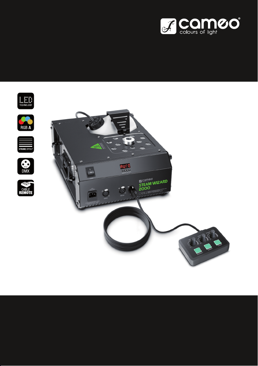
STEAM WIZARD 2000
STEAM WIZARD 2000
LED FOG MACHINE
CLSW2000
USER´S MANUAL
BEDIENUNGSANLEITUNG
MANUEL D`UTILISATION
MANUAL DE USUARIO
INSTRUKCJA OBSŁUGI
MANUALE D‘ USO

CONTENTS / INHALTSVERZEICHNIS / CONTENU / CONTENIDO / TREŚĆ / CONTENUTO
ENGLISH
PREVENTIVE MEASURES 3-4
INTRODUCTION 4
CONNECTIONS, OPERATING AND DISPLAY ELEMENTS 5
OPERATION 6
CABLE REMOTE CONTROL 6-7
INSTALLATION AND ASSEMBLY 7-8
DMX TECHNOLOGY 9
TECHNICAL DATA 10
MANUFACTURER´S DECLARATIONS 10
DMX CONTROL 55
DEUTSCH
SICHERHEITSHINWEISE 11-12
EINFÜHRUNG 12
ANSCHLÜSSE, BEDIEN- UND ANZEIGEELEMENTE 13
BEDIENUNG 14
KABEL-FERNBEDIENUNG 14-15
AUFSTELLUNG UND MONTAGE 15-16
DMX TECHNIK 17
TECHNISCHE DATEN 18
HERSTELLERERKLÄRUNGEN 18
DMX STEUERUNG 55
FRANCAIS
MESURES PRÉVENTIVES 19-20
INTRODUCTION 21
RACCORDEMENTS, ÉLÉMENTS DE COMMANDE ET D’AFFICHAGE
21-22
MODE D’EMPLOI 22
TÉLÉCOMMANDE FILAIRE 23
INSTALLATION ET MONTAGE 24-25
TECHNOLOGIE DMX 25-26
CARACTÉRISTIQUES TECHNIQUES 26
DECLARATIONS 27
PILOTAGE EN MODE DMX 55
ESPAÑOL
MEDIDAS DE SEGURIDAD 28-29
INTRODUCCIÓN 30
CONEXIONES, ELEMENTOS DE MANEJO Y ELEMENTOS DE VISUALI-
ZACIÓN 30-31
FUNCIONAMIENTO 31
MANDO A DISTANCIA POR CABLE 32
INSTALACIÓN Y MONTAJE 33-34
TECNOLOGÍA DMX 34-35
DATOS TÉCNICOS 35-36
DECLARACIÓN DEL FABRICANTE 36
CONTROL DMX 55
POLSKI
ŚRODKI OSTROŻNOŚCI 37-38
WPROWADZENIE 39
GNIAZDA, PANEL OBSŁUGI I WSKAŹNIKI 39-40
OBSŁUGA 40
PILOT PRZEWODOWY 41
USTAWIANIE I MONTAŻ 42-43
TECHNIKA DMX 43-44
DANE TECHNICZNE 44-45
DEKLARACJE PRODUCENTA 45
STEROWANIE DMX 55
ITALIANO
MISURE PRECAUZIONALI 46-47
INTRODUZIONE 48
RACCORDI, ELEMENTI DI COMANDO E DI VISUALIZZAZIONE 48-49
COMANDO 49
TELECOMANDO CON CAVO 50
INSTALLAZIONE E MONTAGGIO 51-52
TECNOLOGIA DMX 52-53
DATI TECNICI 53-54
DICHIARAZIONI DEL PRODUTTORE 54
CONTROLLO DMX 55

ITALIANOPOLSKIESPAÑOL
FRANCAISDEUTSCHENGLISH
3
DMX
ENGLISH
YOU‘VE MADE THE RIGHT CHOICE!
We have designed this product to operate reliably over many years. Please read this User‘s Manual carefully, so that you can begin making
optimum use of your Cameo Light product quickly. Learn more about Cameo Light on our website WWW.CAMEOLIGHT.COM.
PREVENTIVE MEASURES
1. Please read these instructions carefully.
2. Keep all information and instructions in a safe place.
3. Follow the instructions.
4. Observe all safety warnings. Never remove safety warnings or other information from the equipment.
5. Use the equipment only in the intended manner and for the intended purpose.
6. Use only sufficiently stable and compatible stands and/or mounts (for fixed installations). Make certain that wall mounts are properly installed and
secured. Make certain that the equipment is installed securely and cannot fall down.
7. During installation, observ e the applicable safety regulations for your country.
8. Never install and operate the equipment near radiators, heat registers, ovens or other sources of heat. Make certain that the equipment is
always installed so that is cooled sufficiently and cannot overheat.
9. Never place sources of ignition, e.g., burning candles, on the equipment.
10. Ventilation slits must not be blocked.
11. This appliance is designed exclusively for indoor use, do not use this equipment in the immediate vicinity of water (does not apply
to special outdoor equipment - in this case, observe the special instructions noted below). Do not expose this equipment to flammable
materials, fluids or gases.
12. Make certain that dripping or splashed water cannot enter the equipment. Do not place containers filled with liquids, such as vases or
drinking vessels, on the equipment.
13. Make certain that objects cannot fall into the device.
14. Use this equipment only with the accessories recommended and intended by the manufacturer.
15. Do not open or modify this equipment.
16. After connecting the equipment, check all cables in order to prevent damage or accidents, e.g., due to tripping hazards.
17. During transport, make certain that the equipment cannot fall down and possibly cause property damage and personal injuries.
18. If your equipment is no longer functioning properly, if fluids or objects have gotten inside the equipment or if it has been damaged in
anot her way, switch it off immediately and unplug it from the mains outlet (if it is a powered device). This equipment may only be repaired
by authorized, qualified personnel.
19. Clean the equipment using a dry cloth.
20. Comply with all applicable disposal laws in your country. During disposal of packaging, please separate plastic and paper/cardboard.
21. Plastic bags must be kept out of reach of children.
FOR EQUIPMENT THAT CONNECTS TO THE POWER MAINS:
22. CAUTION: If the power cord of the device is equipped with an earthing contact, then it must be connected to an outlet with a protective
ground. Never deactivate the protective ground of a power cord.
23. If the equipment has been exposed to strong fluctuations in temperature (for example, after transport), do not switch it on immediately.
Moisture and condensation could damage the equipment. Do not switch on the equipment until it has reached room temperature.
24. Before connecting the equipment to the power outlet, first verify that the mains voltage and frequency match the values specified on the
equipment. If the equipment has a voltage selection switch, connect the equipment to the power outlet only if the equipment values and the
mains power values match. If the included power cord or power adapter does not fit in your wall outlet, contact your electrician.
25. Do not step on the power cord. Make certain that the power cable does not become kinked, especially at the mains outlet and/or power
adapter and the equipment connector.
26. When connecting the equipment, make certain that the power cord or power adapter is always freely accessible. Always disconnect the
equipment from the power supply if the equipment is not in use or if you want to clean the equipment. Always unplug the power cord and
power adapter from the power outlet at the plug or adapter and not by pulling on the cord. Never touch the power cord and power adapter
with wet hands.
27. Whenever possible, avoid switching the equipment on and off in quick succession because otherwise this can shorten the useful life of
the equipment.
28. IMPORTANT INFORMATION: Replace fuses only with fuses of the same type and rating. If a fuse blows repeatedly, please contact an
authorised service centre.
29. To disconnect the equipment from the power mains completely, unplug the power cord or power adapter from the power outlet.
30. If your device is equipped with a Volex power connector, the mating Volex equipment connector must be unlocked before it can be re-
moved. However, this also means that the equipment can slide and fall down if the power cable is pulled, which can lead to personal injuries
and/or other damage. For this reason, always be careful when laying cables.
31. Unplug the power cord and power adapter from the power outlet if there is a risk of a lightning strike or before extended periods of disuse.
32. The device must only be installed in a voltage-free condition (disconnect the mains plug from the mains).
33. Dust and other debris inside the unit may cause damage. The unit should be regularly serviced or cleaned (no guarantee) depending on
ambient conditions (dust etc., nicotine, fog) by qualified personnel to prevent overheating and malfunction.
34. Please keep a distance of at least 0.5 m to any combustible materials.
35. Power cables to power multiple devices must have a cross-section of at least 1.5 mm². Within the EU, the cables must correspond to
H05VV-F, or similar. Suitable cables are offered by Adam Hall. With these cables, you can connect multiple devices via the power OUT con-
nection to the power IN connection of an additional device. Make sure that the total current consumption of all connected devices does not
exceed the specified value on all connected devices (label on the device). Make sure to keep power cable connections as short as possible.
4
DEUTSCHFRANCAIS
ESPAÑOL
ENGLISH
ITALIANO POLSKI
DMX
CAUTION:
To reduce the risk of electric shock, do not remove cover (or back). There are no user serviceable parts
inside. Maintenance and repairs should be exclusively carried out by qualified service personnel.
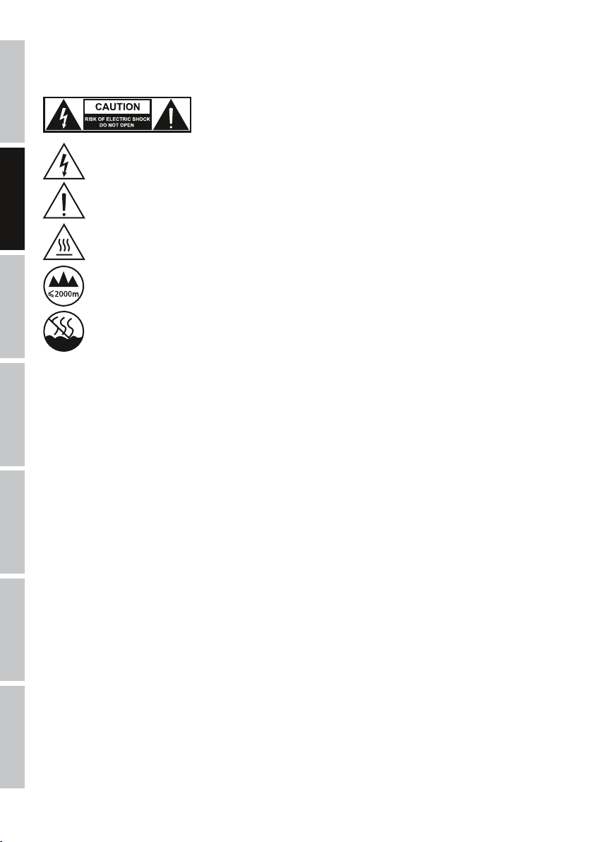
The warning triangle with lightning symbol indicates dangerous uninsulated voltage inside the unit, which may cause an
electrical shock.
The warning triangle with exclamation mark indicates important operating and maintenance instructions.
Warning! This symbol indicates a hot surface. Certain parts of the housing can become hot during operation. After use, wait for
a cool-down period of at least 10 minutes before handling or transporting the device.
Warning! This device is designed for use below 2000 metres in altitude.
Warning! This product is not intended for use in tropical climates.
CAUTION! HIGH VOLUMES IN AUDIO PRODUCTS!
This device is meant for professional use. Therefore, commercial use of this equipment is subject to the respectively applicable national accident
prevention rules and regulations. As a manufacturer, Adam Hall is obligated to notify you formally about the existence of potential health risks.
Hearing damage due to high volume and prolonged exposure: When in use, this product is capable of producing high sound-pressure levels (SPL)
that can lead to irreversible hearing damage in performers, employees, and audience members. For this reason, avoid prolonged exposure to
volumes in excess of 90 dB.
CAUTION! IMPORTANT INFORMATION REGARDING FOG MACHINES!
1. This product has been developed for professional use in the field of event technology and is not intended for use in the home!
2. Use only Cameo fog fluid (water-based) and never add flammable liquid to the container!
3. Switch off the fog machine and disconnect it from the power supply before filling the container!
4. Operate the fog machine only in well-ventilated rooms!
5. Do not leave the fog machine running unattended!
6. The fog outlet nozzle becomes very hot during operation. Do not touch the outlet nozzle during operation and maintain a minimum
distance of 50cm from it! Ensure that the device has cooled down completely before cleaning or transporting it!
7. The fog mist emitted is very hot! Never direct the outlet nozzle towards people or animals! RISK OF BURNING!
8. If the fog machine is installed overhead, ensure that people or animals are not allowed directly underneath it! RISK OF BURNING!
9. Never direct the fog outlet nozzle towards open flames or flammable materials!
INTRODUCTION
LED FOG MACHINE
CLSW2000
CONTROL FUNCTIONS
4-channel DMX control
Cable remote control
FEATURES
LED fog machine with 12 x 10 W 4-in-1 RGBA LEDs, pyrotechnic-similar effects, DMX-512 control, overheating protection and empty
canister warning, rubber feet, traverse installation at any angle, safety eyelets, cable remote control included, operating voltage 230 V AC /
50 Hz, power consumption 1200 W.
ITALIANOPOLSKIESPAÑOL
FRANCAISDEUTSCHENGLISH
5
DMX
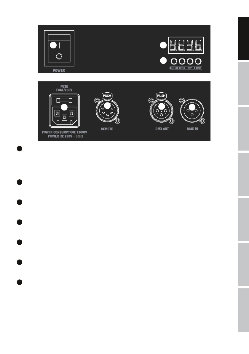
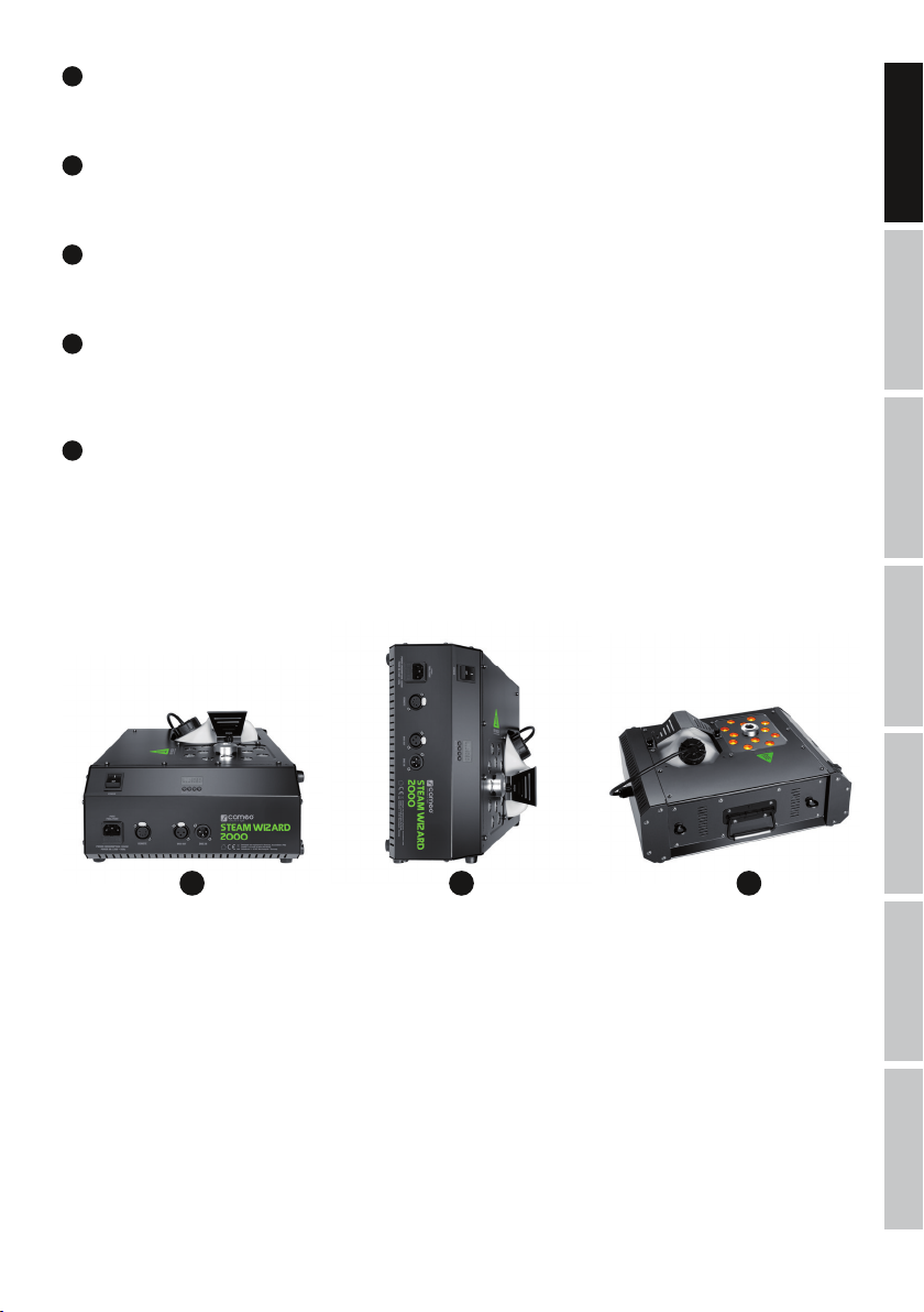
CONNECTIONS, OPERATING AND DISPLAY ELEMENTS
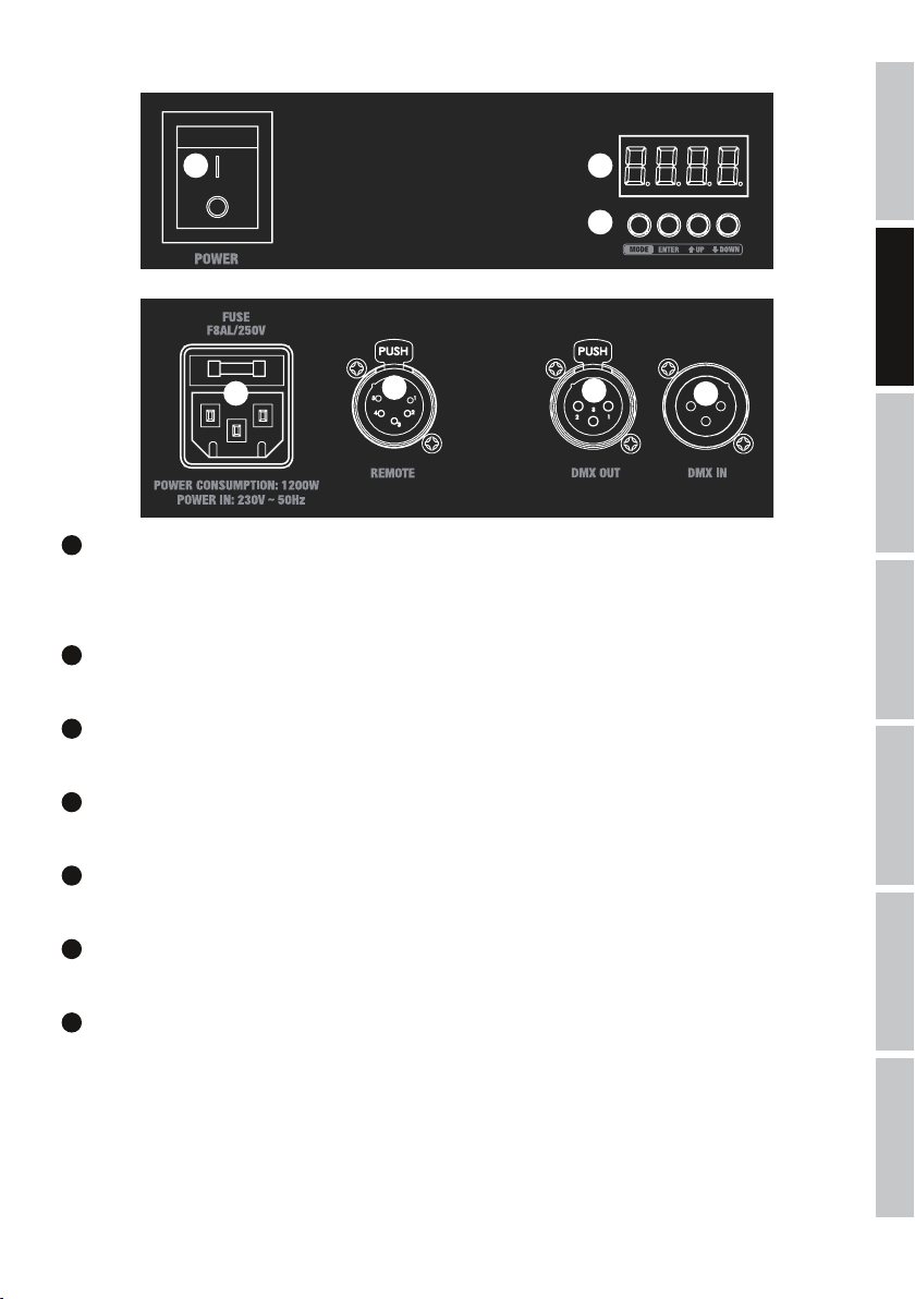
1
POWER IN
IEC mains socket with built-in fuse holder. A suitable power cable is included.
IMPORTANT:
Replace the fuse only with a fuse of the same type and of the same value according to the stamp on the device! In the event
of repeated fuse failure, please contact an authorised service centre.
2
POWER
On / Off switch for power supply to the device.
3
REMOTE
5-pin XLR socket for connection of the cable remote control (included).
4
DMX IN
Male 3-pin XLR socket for connection to a DMX control device (e.g. DMX console).
5
DMX OUT
Female 3-pin XLR socket for sending the DMX control signal.
6
LED DISPLAY
The four-digit LED display shows the operating status, mode and other system information.
7
CONTROL BUTTONS
MODE: Selection of menu items. Move up one level in the menu structure.
ENTER: Confirm value changes.
UP and DOWN: Changing DMX address and settings.
2 6
7
1
3
5
4
6
DEUTSCHFRANCAIS
ESPAÑOL
ENGLISH
ITALIANO POLSKI
DMX
OPERATION
Switch off the LED fog machine and disconnect it from the power supply before filling the container! Fill the container of the LED fog
machine only with Cameo fog fluid (preferably Cameo Fast Fluid) and close it carefully. The fog machine is ready for operation a few minutes
after switching on (approx. 5 minutes). It features a canister light (LED) and a 4-digit LED display to provide information on the operating
status. Display elements canister light and display are activated in the factory settings.
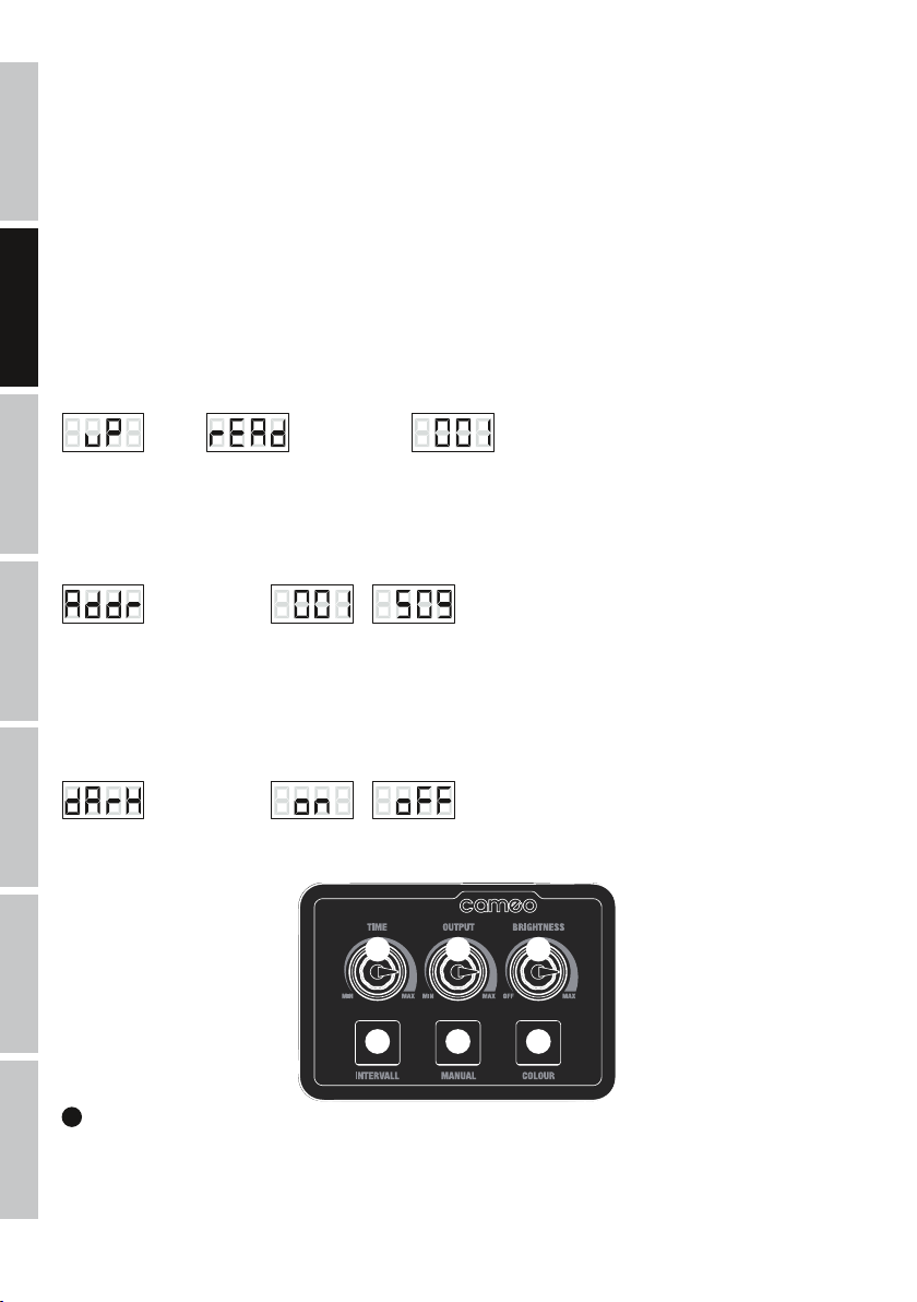
1. During warm-up phase of the evaporator, the canister is permanently lit up in red, the display shows "uP" and the device is not ready for
operation.
2. Whilst ready for operation, the canister is constantly lit blue, and depending upon settings, the display will show either "rEAd" (control via
cable remote control), or the currently configured DMX start address (control via DMX controller).
3. If the fog fluid in the container is all used up, the canister light will start to flash red after approximately 2 minutes, two minus symbols
will be shown in the display and the LED fog machine will switch to error mode. Switch off the unit and disconnect it from the mains. Fill the
container with fog fluid and switch the unit back on. Follow the same procedure if you notice that the fluid has all been used before the fog
machine switches to error mode.
If there is a DMX signal to the device, the DMX mode is activated automatically and the currently configured DMX start address will appear
in the display. The cable remote control is disabled in this case. If there is no DMX signal, the LED fog machine can be controlled with the
supplied cable remote control.
The evaporator is LED fog machine ready (ready).
Control via cable remote control.
LED fog machine ready,
DMX signal is present.
CONFIGURE DMX START ADDRESS
Press the MODE button repeatedly until "Addr" appears in the display. Now press ENTER and configure the DMX start address using the UP
and DOWN buttons as required (001 - 509). Confirm your entry with ENTER.
-> ENTER -> UP/DOWN
-
-> ENTER
<- MODE
ADJUSTMENT OF DISPLAY ELEMENTS
In some cases, canister lighting and LED display can have a disturbing effect and can therefore be switched off (the empty canister warning
is excluded and will be activated in the event of an error).
Press the MODE button repeatedly until the display shows "dArk", press ENTER and select the desired setting using the UP and DOWN buttons
(on = container lighting switched off, display switched off after approx. 15 seconds / oFF = container lighting and display permanently active).
Confirm your entry with ENTER.
-> ENTER -> UP/DOWN
/
-> ENTER
<- MODE
1
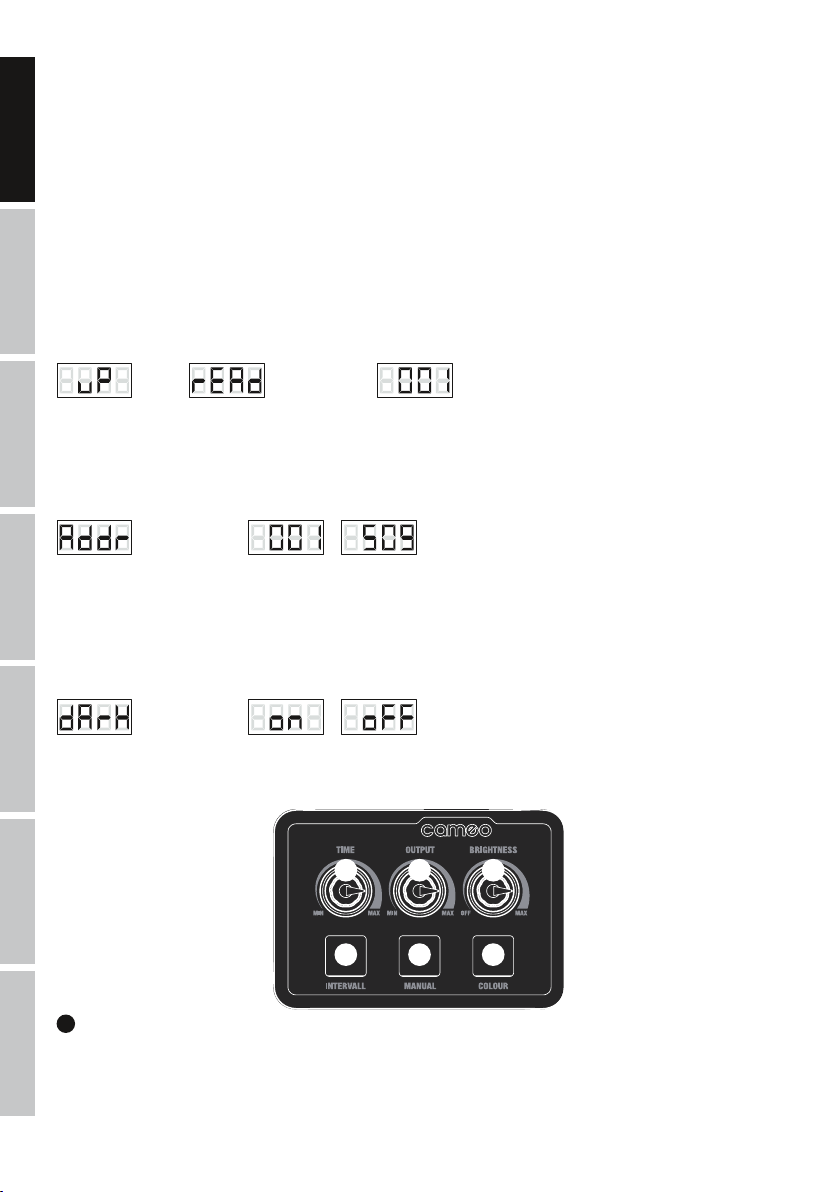
INTERVAL
Interval function for fog output and simultaneous illumination of LEDs. Press the button to start the interval function and again to quit. The
fog burst and LED illumination period is approximately 2 seconds. Configure the time interval between bursts with the TIME dial. If the
interval function is activated, the indicator LED on the button is lit. During fog bursts, “FoG” appears on the display.
CABLE REMOTE CONTROL
2 4 6
1 3 5
ITALIANOPOLSKIESPAÑOL
FRANCAISDEUTSCHENGLISH
7
DMX
2
TIME
Knob for adjustment of time between bursts of the interval function (all the way to the left = continuous bursts / 0 second interval, all the way to
the right = approx. 60 seconds interval). An integrated LED indicator lights up as soon as the heating-up phase of the evaporator is complete.
3
MANUAL
Button for manual triggering of the combined effect. Fog burst and LED illumination continues for as long as the button is pressed. When the
button is pressed the indicator LED in the button is lit. During fog bursts, “FoG” appears on the display.
4
OUTPUT
Knob to adjust the fog burst density quantity (all the way to the left = fog output disabled / 0%, all the way to the right = maximum fog
density / 100%). An integrated LED indicator lights up as soon as the heating-up phase of the evaporator is complete.
5
COLOUR
Button to adjust the LED light colour. Press and hold the button for approximately 1 second until the LEDs are turned on, then press briefly
and repeatedly to select the desired colour (14 colour presets and automatic colour change). The LEDs are lit for approx. 5 seconds, as is
the LED indicator in the button.
6
BRIGHTNESS
Knob to adjust brightness effect (all the way to the left = blackout / 0%, all the way to the right = maximum brightness / 100%). An integrated
LED indicator lights up as soon as the heating-up phase of the evaporator is complete.
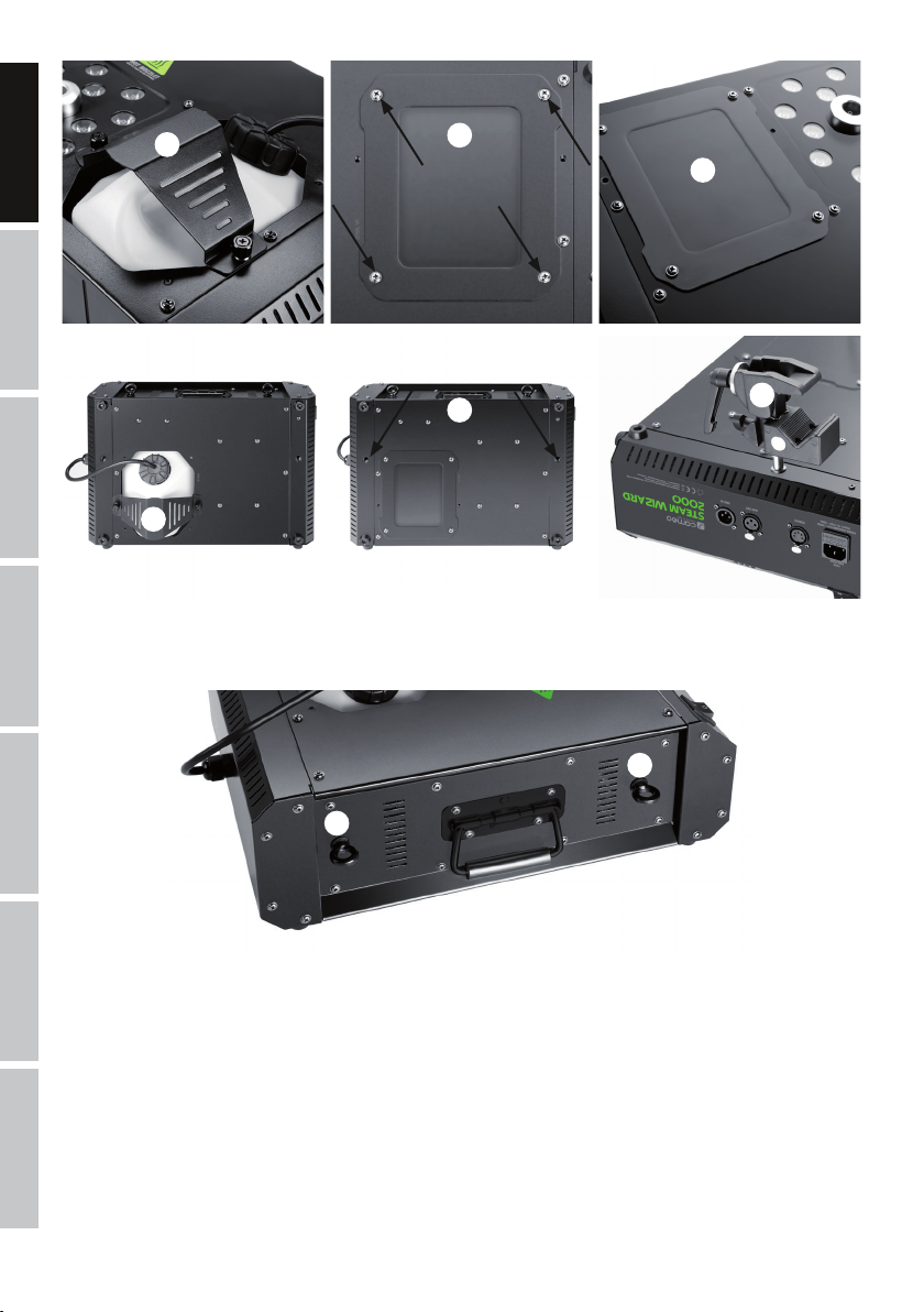
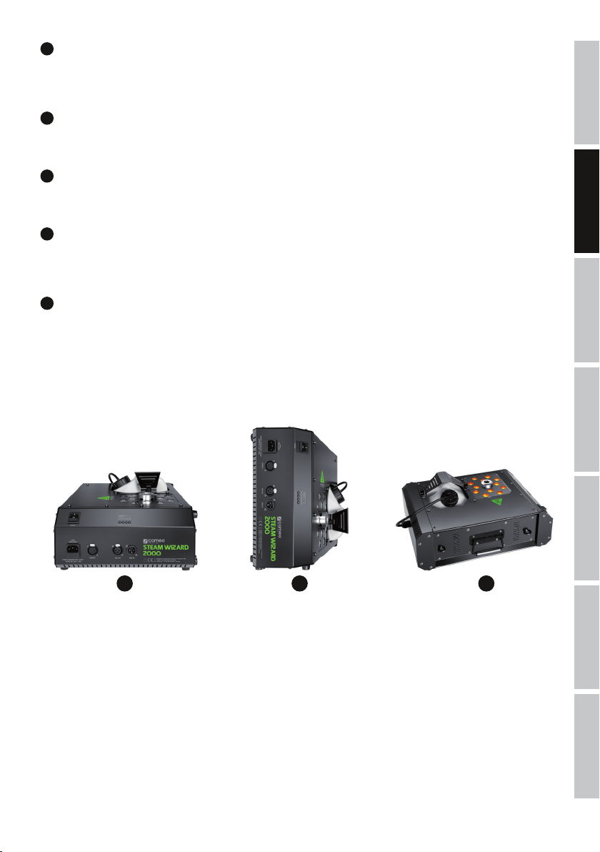
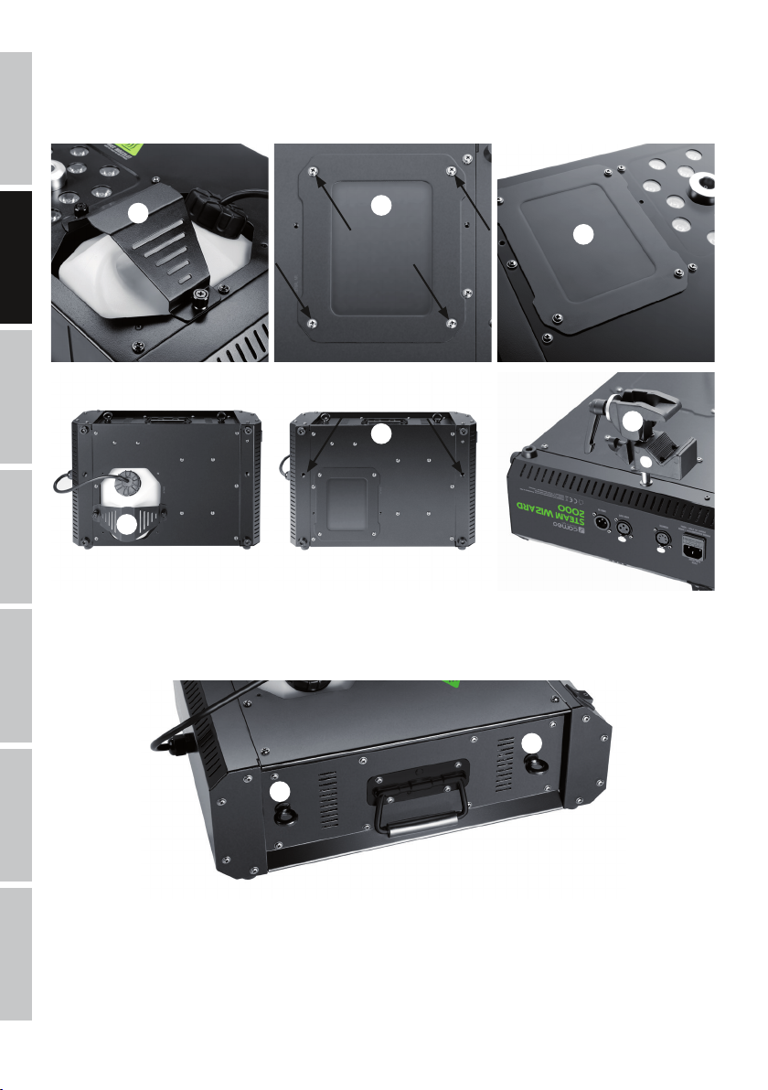
INSTALLATION
For installation on a level surface, the LED fog machine features four rubber feet on the base (Fig. A, vertical fog output) and on one side (Fig
B, horizontal fog output). For convenient transportation, a folding handle is located on the side of the housing (Fig. C).
A B C
Because the LED fog machine can be installed at any desired angle on a traverse, it features a top-or-bottom-loading canister tray. Load
the canister tray from the bottom if the LED fog machine is installed at an angle greater than 90°. To do this, remove the canister retaining
clamp (Fig. D), remove the canister and remove the
canister shelves from the bottom of the housing using a suitable tool (Fig. E, 4 screws, screwdriver PH2). Now install the canister shelves on
the top side of the housing in the designated position (Fig. F), place the canister in the canister tray and secure it with the canister retaining
clamp (Fig. G). Make sure that the canister is held in place firmly.
8
DEUTSCHFRANCAIS
ESPAÑOL
ENGLISH
ITALIANO POLSKI
DMX
D
F
E
G
I
H
For traverse installation, two M10 threads are located on the base of the housing (Fig. H) to receive the traverse mounting bolts. (Fig. I, not included).
Secure the device via the integrated safety eyelets (Fig. J) and appropriate securing cables (not included). IMPORTANT: Overhead installation must
only be carried out by qualified personnel. When installing, please refer to the points under “CAUTION! IMPORTANT INFORMATION REGARDING FOG
MACHINES!” in this manual.
J
J
ITALIANOPOLSKIESPAÑOL
FRANCAISDEUTSCHENGLISH
9
DMX
DMX TECHNOLOGY
DMX-512
DMX (Digital Multiplex) is the designation for a universal transmission protocol for
communications between corresponding devices and controllers. A DMX controller sends
DMX data to the connected DMX device(s). The DMX data is always transmitted as a serial
data stream that is forwarded from one connected device to the next via the "DMX IN" and
"DMX OUT" connectors (XLR plug-type connectors) that are found on every DMX-capable
device, provided the maximum number of devices does not exceed 32 units. The last device
in the chain needs to be equipped with a terminator (terminating resistor).
DMX CONNECTION
DMX is the common "language" via which a very wide range of types and models of equipment from various manufacturers can
be connected with one another and controlled via a central controller, provided that all of the devices and the controller are DMX
compatible. For optimum data transmission, it is necessary to keep the connecting cables between the individual devices as short as
possible. The order in which the devices are integrated in the DMX network has no influence on the addresses. Thus the device with
the DMX address 1 can be located at any position in the (serial) DMX chain: at the beginning, at the end or somewhere in the middle.
If the DMX address 1 is assigned to a device, the controller "knows" that it should send all data allocated to address 1 to this device
regardless of its position in the DMX network.
SERIAL CONNECTION OF MULTIPLE LIGHTS
1. Connect the male XLR connector (3-pin or 5-pin) of the DMX cable to the DMX output (female XLR socket) of the first DMX device
(e.g. DMX-Controller).
2. Connect the female 3-pin XLR connector of the DMX cable connected to the first projector to the DMX input (male 3-pin socket)
of the next DMX device. In the same way, connect the DMX output of this device to the DMX input of the next device and repeat until
all devices have been connected. Please note that as a rule, DMX devices are connected in series and connections cannot be shared
without active splitters. The maximum number of DMX devices in a DMX chain should not exceed 32 units.
The Adam Hall 3 STAR, 4 STAR, and 5 STAR product ranges include an extensive selection of suitable cables.
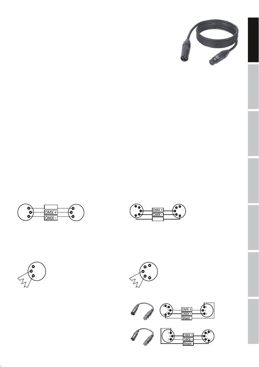
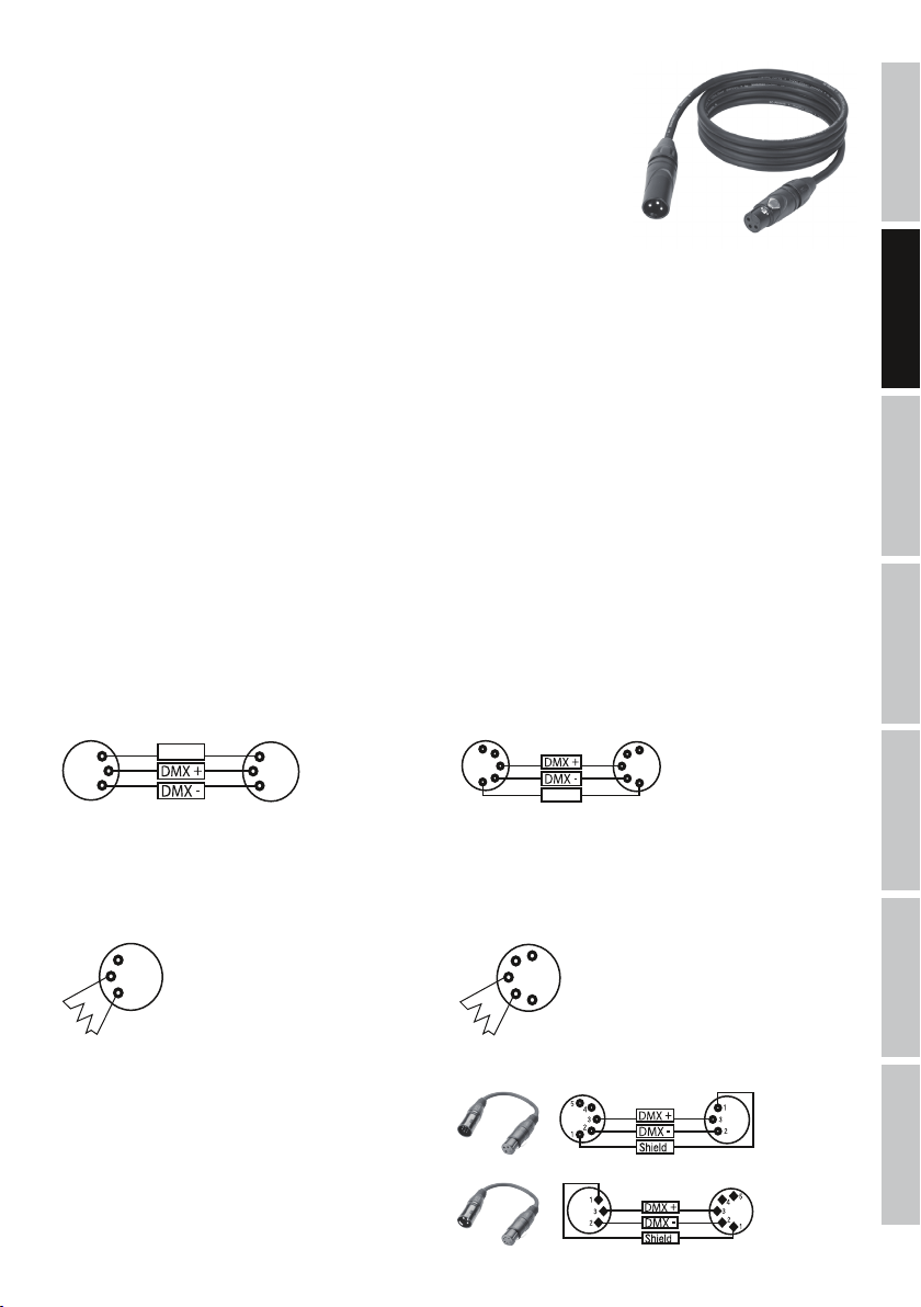
DMX CABLES
When fabricating your own cables, always observe the illustrations on this page. Never connect the shielding of the cable to the ground
contact of the plug, and always make certain that the shielding does not come into contact with the housing of the XLR plug. If the shielding
is connected to the ground, this can lead to short-circuiting and system malfunctions.
Pin Assignment
DMX cable with 3-pin XLR connectors: DMX cable with 5-pin XLR connectors (pin 4 and 5 are not used):
Shield
2
3
1
2
3
1
1
2
3
4
5
1
2
3
4
5
Shield
DMX TERMINATORS (TERMINATING RESISTORS)
To prevent system errors, the last device in a DMX chain needs to be equipped with a terminating resistor (120 ohm, 1/4 Watt).
3-pin XLR connector with a terminating resistor: K3DMXT3
5-pin XLR connector with a terminating resistor: K3DMXT5
Pin Assignment
3-pin XLR connector: 5-pin XLR connector:
2
3
1
1
2
3
4
5
DMX ADAPTER
The combination of DMX devices with 3-pin connectors and DMX devices with 5-pin connectors in a DMX chain is possible with suitable adapters.
Pin Assignment
DMX Adapter 5-pin XLR male to 3-pin XLR female: K3DGF0020
Pins 4 and 5 are not used.
Pin Assignment
DMX Adapter 3-pin XLR male to 5-pin XLR female: K3DHM0020
Pins 4 and 5 are not used.
10
DEUTSCHFRANCAIS
ESPAÑOL
ENGLISH
ITALIANO POLSKI
DMX
TECHNICAL DATA
Model name: CLSW2000
Product type: Effect fog machine
Type: Fog generator operating on evaporation principle combined with LED spotlights
Warm-up time: Approximately 5 minutes
Colour spectrum LED: RGBA
Number of LEDs: 12
LED type: 10 W 4-in-1
DMX input: 3-pin male XLR
DMX output: 3-pin female XLR
DMX mode: 4 Channel
DMX functions: fog density, dimmer, strobe, colour macros, colour change, colour blend
Cable remote control functions: fog density, dimmer, colour macros, colour change, intermittent function, manual
operation
Control: DMX512
Controls: mode, enter, up, down, cable remote control
Display elements: 4-digit LED display, canister light
Operating voltage: 230 V AC / 50 Hz
Power consumption: 1200 W
Overheating protection: Heating element with thermostat
Power connection: IEC input
Fuse: F8AL / 250 V (5 x 20 mm)
Ambient temperature (in operation): 5°C - 40°C
Relative air humidity: < 85%, non-condensing
Housing material: Metal
Housing colour: black
Dimensions (W x H x D): 455 x 197 x 318mm.
Weight (without canister): 8.3kg
Additional features: carrying handle, canister and cap with pressure compensation valve and suction hose
included, 2 x M10 threads, 2 x safety eyelets, installation at any angle, canister compart-
ment on the top or bottom, 8 rubber feet, cable remote control with 10m cable
MANUFACTURER´S DECLARATIONS
MANUFACTURER‘S WARRANTY & LIMITATIONS OF LIABILITY
You can find our current warranty conditions and limitations of liability at: http://www.adamhall.com/media/shop/downloads/documents/
manufacturersdeclarations.pdf. To request warranty service for a product, please contact Adam Hall GmbH, Daimler Straße 9, 61267 Neu
Anspach / Email: Info@adamhall.com / +49 (0)6081 / 9419-0.
CORRECT DISPOSAL OF THIS PRODUCT
(valid in the European Union and other European countries with a differentiated waste collection system)
This symbol on the product, or on its documents indicates that the device may not be treated as household waste. This is to avoid
environmental damage or personal injury due to uncontrolled waste disposal. Please dispose of this product separately from other waste
and have it recycled to promote sustainable economic activity. Household users should contact either the retailer where they purchased
this product, or their local government office, for details on where and how they can recycle this item in an environmentally friendly manner.
Business users should contact their supplier and check the terms and conditions of the purchase contract. This product should not be mixed
with other commercial waste for disposal.
CE Compliance
Adam Hall GmbH states that this product meets the following guidelines (where applicable):
R&TTE (1999/5/EC) or RED (2014/53/EU) from June 2017
Low voltage directive (2014/35/EU)
EMV directive (2014/30/EU)
RoHS (2011/65/EU)
The complete declaration of conformity can be found at www.adamhall.com.
Furthermore, you may also direct your enquiry to info@adamhall.com.

ITALIANOPOLSKIESPAÑOL
FRANCAISDEUTSCHENGLISH
11
DMX
DEUTSCH
SIE HABEN DIE RICHTIGE WAHL GETROFFEN!
Dieses Gerät wurde unter hohen Qualitätsanforderungen entwickelt und gefertigt, um viele Jahre einen reibungslosen Betrieb zu gewähr-
leisten. Bitte lesen Sie diese Bedienungsanleitung sorgfältig, damit Sie Ihr neues Produkt von Cameo Light schnell und optimal einsetzen
können. Weitere Informationen über Cameo Light erhalten Sie auf unserer Website WWW.CAMEOLIGHT.COM.
SICHERHEITSHINWEISE
1. Lesen Sie diese Anleitung bitte sorgfältig durch.
2. Bewahren Sie alle Informationen und Anleitungen an einem sicheren Ort auf.
3. Befolgen Sie die Anweisungen.
4. Beachten Sie alle Warnhinweise. Entfernen Sie keine Sicherheitshinweise oder andere Informationen vom Gerät.
5. Verwenden Sie das Gerät nur in der vorgesehenen Art und Weise.
6. Verwenden Sie ausschließlich stabile und passende Stative bzw. Befestigungen (bei Festinstallationen). Stellen Sie sicher, dass Wandhalterungen
ordnungsgemäß installiert und gesichert sind. Stellen Sie sicher, dass das Gerät sicher installiert ist und nicht herunterfallen kann.
7. Beachten Sie bei der Installation die für Ihr Land geltenden Sicherheitsvorschriften.
8. Installieren und betreiben Sie das Gerät nicht in der Nähe von Heizkörpern, Wärmespeichern, Öfen oder sonstigen Wärmequellen. Sorgen
Sie dafür, dass das Gerät immer so installiert ist, dass es ausreichend gekühlt wird und nicht überhitzen kann.
9. Platzieren Sie keine Zündquellen wie z.B. brennende Kerzen auf dem Gerät.
10. Lüftungsschlitze dürfen nicht blockiert werden.
11. Das Gerät wurde ausschließlich für die Verwendung in Innenräumen entwickelt, betreiben Sie das Gerät nicht in unmittelbarer Nähe von
Wasser (gilt nicht für spezielle Outdoor Geräte - beachten Sie in diesem Fall bitte die im Folgenden vermerkten Sonderhinweise). Bringen Sie
das Gerät nicht mit brennbaren Materialien, Flüssigkeiten oder Gasen in Berührung.
12. Sorgen Sie dafür, dass kein Tropf- oder Spritzwasser in das Gerät eindringen kann. Stellen Sie keine mit Flüssigkeit gefüllten Behältnisse
wie Vasen oder Trinkgefäße auf das Gerät.
13. Sorgen Sie dafür, dass keine Gegenstände in das Gerät fallen können.
14. Betreiben Sie das Gerät nur mit dem vom Hersteller empfohlenen und vorgesehenen Zubehör.
15. Öffnen Sie das Gerät nicht und verändern Sie es nicht.
16. Überprüfen Sie nach dem Anschluss des Geräts alle Kabelwege, um Schäden oder Unfälle, z. B. durch Stolperfallen zu vermeiden.
17. Achten Sie beim Transport darauf, dass das Gerät nicht herunterfallen und dabei möglicherweise Sach- und Personenschäden verursachen kann.
18. Wenn Ihr Gerät nicht mehr ordnungsgemäß funktioniert, Flüssigkeiten oder Gegenstände in das Geräteinnere gelangt sind, oder das Gerät
anderweitig beschädigt wurde, schalten Sie es sofort aus und trennen es von der Netzsteckdose (sofern es sich um ein aktives Gerät handelt).
Dieses Gerät darf nur von autorisiertem Fachpersonal repariert werden.
19. Verwenden Sie zur Reinigung des Geräts ein trockenes Tuch.
20. Beachten Sie alle in Ihrem Land geltenden Entsorgungsgesetze. Trennen Sie bei der Entsorgung der Verpackung bitte Kunststoff und
Papier bzw. Kartonagen voneinander.
21. Kunststoffbeutel müssen außer Reichweite von Kindern aufbewahrt werden.
BEI GERÄTEN MIT NETZANSCHLUSS:
22. ACHTUNG: Wenn das Netzkabel des Geräts mit einem Schutzkontakt ausgestattet ist, muss es an einer Steckdose mit Schutzleiter
angeschlossen werden. Deaktivieren Sie niemals den Schutzleiter eines Netzkabels.
23. Schalten Sie das Gerät nicht sofort ein, wenn es starken Temperaturschwankungen ausgesetzt war (beispielsweise nach dem Transport).
Feuchtigkeit und Kondensat könnten das Gerät beschädigen. Schalten Sie das Gerät erst ein, wenn es Zimmertemperatur erreicht hat.
24. Bevor Sie das Gerät an die Steckdose anschließen, prüfen Sie zuerst, ob die Spannung und die Frequenz des Stromnetzes mit den auf
dem Gerät angegebenen Werten übereinstimmen. Verfügt das Gerät über einen Spannungswahlschalter, schließen Sie das Gerät nur an die
Steckdose an, wenn die Gerätewerte mit den Werten des Stromnetzes übereinstimmen. Wenn das mitgelieferte Netzkabel bzw. der mitgelie-
ferte Netzadapter nicht in Ihre Netzsteckdose passt, wenden Sie sich an Ihren Elektriker.
25. Treten Sie nicht auf das Netzkabel. Sorgen Sie dafür, dass spannungsführende Kabel speziell an der Netzbuchse bzw. am Netzadapter
und der Gerätebuchse nicht geknickt werden.
26. Achten Sie bei der Verkabelung des Geräts immer darauf, dass das Netzkabel bzw. der Netzadapter stets frei zugänglich ist. Trennen Sie
das Gerät stets von der Stromzuführung, wenn das Gerät nicht benutzt wird, oder Sie das Gerät reinigen möchten. Ziehen Sie Netzkabel und
Netzadapter immer am Stecker bzw. am Adapter und nicht am Kabel aus der Steckdose. Berühren Sie Netzkabel und Netzadapter niemals
mit nassen Händen.
27. Schalten Sie das Gerät möglichst nicht schnell hintereinander ein und aus, da sonst die Lebensdauer des Geräts beeinträchtigt werden könnte.
28. WICHTIGER HINWEIS: Ersetzen Sie Sicherungen ausschließlich durch Sicherungen des gleichen Typs und Wertes. Sollte eine Sicherung
wiederholt auslösen, wenden Sie sich bitte an ein autorisiertes Servicezentrum.
29. Um das Gerät vollständig vom Stromnetz zu trennen, entfernen Sie das Netzkabel bzw. den Netzadapter aus der Steckdose.
30. Wenn Ihr Gerät mit einem Volex-Netzanschluss bestückt ist, muss der passende Volex-Gerätestecker entsperrt werden, bevor er entfernt
werden kann. Das bedeutet aber auch, dass das Gerät durch ein Ziehen am Netzkabel verrutschen und herunterfallen kann, wodurch Perso-
nen verletzt werden und/oder andere Schäden auftreten können. Verlegen Sie Ihre Kabel daher immer sorgfältig.
31. Entfernen Sie Netzkabel und Netzadapter aus der Steckdose bei Gefahr eines Blitzschlags oder wenn Sie das Gerät länger nicht verwenden.
32. Das Gerät darf nur im spannungsfreien Zustand (Trennung des Netzsteckers vom Stromnetz) installiert werden.
33. Staub und andere Ablagerungen im Inneren des Geräts können es beschädigen. Das Gerät sollte je nach Umgebungsbedingungen
(Staub, Nikotin, Nebel etc.) regelmäßig von qualifiziertem Fachpersonal gewartet bzw. gesäubert werden (keine Garantieleistung),
um Überhitzung und Fehlfunktionen zu vermeiden.
34. Der Abstand zu brennbaren Materialien muss mindestens 0,5 m betragen.
35. Netzleitungen zur Spannungsversorgung mehrerer Geräte müssen mindestens 1,5 mm² Aderquerschnitt aufweisen. In der EU müssen
12
DEUTSCHFRANCAIS
ESPAÑOL
ENGLISH
ITALIANO POLSKI
DMX
die Leitungen H05VV-F, oder gleichartig, entsprechen. Geeignete Leitungen werden von Adam Hall angeboten. Mit diesen Leitungen können
Sie mehrere Geräte über den Power out Anschluss mit dem Power IN Anschluss eines weiteren Gerätes verbinden. Beachten Sie, dass die
gesamte Stromaufnahme aller angeschlossenen Geräte den vorgegebenen Wert nicht überschreitet (Aufdruck auf dem Gerät). Achten Sie
darauf, Netzleitungen so kurz wie möglich zu halten.
ACHTUNG
Entfernen Sie niemals die Abdeckung, da sonst das Risiko eines elektrischen Schlages besteht. Im
Inneren des Geräts befinden sich keine Teile, die vom Bediener repariert oder gewartet werden können.
Lassen Sie Wartung und Reparaturen ausschließlich von qualifiziertem Servicepersonal durchführen.
Das gleichseitige Dreieck mit Blitzsymbol warnt vor nichtisolierten, gefährlichen Spannungen im Geräteinneren, die einen
elektrischen Schlag verursachen können.
Das gleichseitige Dreieck mit Ausrufungszeichen kennzeichnet wichtige Bedienungs- und Wartungshinweise.
Warnung! Dieses Symbol kennzeichnet heiße Oberflächen. Während des Betriebs können bestimmte Teile des Gehäuses heiß
werden. Berühren oder transportieren Sie das Gerät nach einem Einsatz erst nach einer Abkühlzeit von mindestens 10 Minuten.
Warnung! Dieses Gerät ist für eine Nutzung bis zu einer Höhe von maximal 2000 Metern über dem Meeresspiegel bestimmt.
Warnung! Dieses Gerät ist nicht für den Einsatz in tropischen Klimazonen bestimmt.
VORSICHT! WICHTIGE HINWEISE IN BEZUG AUF LICHT-PRODUKTE!
1. Das Produkt ist für den professionellen Einsatz im Bereich der Veranstaltungstechnik entwickelt worden und ist nicht für die Raumbeleuchtung in
Haushalten geeignet.
2. Blicken Sie niemals, auch nicht kurzzeitig, direkt in den Lichtstrahl.
3. Blicken Sie niemals mit optischen Geräten wie Vergrößerungsgläsern in den Lichtstrahl.
4. Stroboskopeffekte können unter Umständen bei empfindlichen Menschen epileptische Anfälle auslösen! Epilepsiekranke Menschen
sollten daher unbedingt Orte meiden, an denen Stroboskope eingesetzt werden.
VORSICHT! WICHTIGE HINWEISE IN BEZUG AUF NEBELMASCHINEN!
1. Das Produkt ist für den professionellen Einsatz im Bereich der Veranstaltungstechnik entwickelt worden und ist nicht für den Betrieb in
Haushalten geeignet!
2. Verwenden Sie ausschließlich Cameo Nebelfluid (wasserbasierend) und füllen Sie niemals brennbare Flüssigkeiten in den Kanister!
3. Schalten Sie die Nebelmaschine aus und trennen sie vom Netz, bevor Sie den Kanister befüllen!
4. Betreiben Sie die Nebelmaschine ausschließlich in gut belüfteten Räumen!
5. Betreiben Sie die Nebelmaschine niemals unbeaufsichtigt!
6. Die Nebelaustrittsdüse wird im Betrieb sehr heiß. Berühren Sie die Austrittsdüse nicht während des Betriebs und halten einen Mindestabstand
von 50cm ein! Stellen Sie vor dem Reinigen und Transportieren sicher, dass das Gerät vollständig abgekühlt ist!
7. Der austretende Nebel ist sehr heiß! Richten Sie die Austrittsdüse niemals auf Personen und Tiere! VERBRENNUNGSGEFAHR!
8. Achten Sie darauf, dass sich Personen und Tiere bei der Überkopfmontage nicht direkt unterhalb von Nebelmaschinen aufhalten dürfen!
VERBRENNUNGSGEFAHR!
9. Richten Sie die Nebelaustrittsdüse niemals auf offene Flammen und brennbare Materialien!
EINFÜHRUNG
LED NEBELMASCHINE
CLSW2000
STEUERUNGSFUNKTIONEN
4-Kanal DMX-Steuerung
Kabel-Fernbedienung
EIGENSCHAFTEN
LED Nebelmaschine mit 12 x 10W 4in1 RGBA LEDs, Effekt ähnlich Pyrotechnik, DMX-512 Steuerung, Überhitzungsschutz und Warnung bei
leerem Kanister, Gummifüße, Traversenmontage in beliebigem Winkel, Safety Schraubösen, Kabel-Fernbedienung inklusive, Betriebsspannung
230V AC / 50Hz, Leistungsaufnahme 1200W.
ITALIANOPOLSKIESPAÑOL
FRANCAISDEUTSCHENGLISH
13
DMX
ANSCHLÜSSE, BEDIEN- UND ANZEIGEELEMENTE
1
POWER IN
IEC Netzbuchse mit integriertem Sicherungshalter. Ein geeignetes Netzkabel befindet sich im Lieferumfang.
WICHTIGER HINWEIS: Ersetzen Sie die Sicherung ausschließlich durch eine Sicherung des gleichen Typs und mit gleichen Werten entsprechend
des Aufdrucks auf dem Gerät! Sollte die Sicherung wiederholt auslösen, wenden Sie sich bitte an ein autorisiertes Servicezentrum.
2
POWER
Ein- / Ausschalter für die Spannungszufuhr des Geräts.
3
REMOTE
5-polige XLR-Buchse zum Anschließen der Kabel-Fernbedienung (im Lieferumfang).
4
DMX IN
Männliche 3-Pol XLR-Buchse zum Anschließen eines DMX-Kontrollgeräts (z.B. DMX-Pult).
5
DMX OUT
Weibliche 3-Pol XLR-Buchse zum Weiterleiten des DMX-Steuersignals.
6
LED DISPLAY
Das vierstellige LED-Display zeigt den Betriebszustand, die Betriebsart und weitere Systeminformationen an.
7
BEDIENTASTER
MODE: Auswahl der Menüpunkte. In der Menüstruktur eine Ebene höher gelangen.
ENTER: Bestätigen von Wertänderungen.
UP und DOWN: Ändern von DMX-Adresse und Einstellungen.
2 6
7
1
3
5
4
14
DEUTSCHFRANCAIS
ESPAÑOL
ENGLISH
ITALIANO POLSKI
DMX
BEDIENUNG
Schalten Sie die LED-Nebelmaschine aus und trennen sie stets vom Netz, bevor Sie den Kanister befüllen. Befüllen Sie den Kanister der
LED-Nebelmaschine ausschließlich mit Cameo Nebelfluid (vorzugsweise Cameo Fast Fluid) und verschließen ihn sorgfältig. Wenige Minuten
nach dem Einschalten ist die LED-Nebelmaschine betriebsbereit (ca. 5 Minuten). Sie verfügt über eine Kanisterbeleuchtung (LED) und das
4-stellige LED-Display, die über den Betriebszustand Auskunft geben. In der Einstellung ab Werk sind die Anzeigeelemente Kanisterbeleuchtung
und Display aktiviert:
1. Während der Aufheizphase des Verdampfers leuchtet der Kanister permanent rot, im Display wird „uP“ angezeigt und das Gerät ist nicht
betriebsbereit.
2. Während der Betriebsbereitschaft leuchtet der Kanister permanent blau, im Display wird, je nach Ansteuerung, „rEAd“ (Ansteuerung via
Kabel-Fernbedienung), oder die aktuell eingestellte DMX-Startadresse angezeigt (Ansteuerung via DMX-Controller).
3. Ist das Nebelfluid im Kanister verbraucht, fängt die Kanisterbeleuchtung nach ca. 2 Minuten an rot zu blinken, im Display blinken zwei
Minuszeichen und die LED-Nebelmaschine wechselt in den Fehlermodus. Schalten Sie das Gerät aus und trennen es vom
Netz, befüllen den Kanister mit Nebelfluid und schalten das Gerät wieder ein. Gehen Sie in gleicher Weise vor, falls Sie bevor
die Nebelmaschine in den Fehlermodus wechselt, bemerken, dass das Nebelfluid verbraucht ist.
Liegt ein DMX-Signal am Gerät an, wird automatisch die DMX-Betriebsart aktiviert und die aktuell eingestellte DMX-Startadresse wird im
Display angezeigt. Die Steuerung via Kabel-Fernbedienung ist in diesem Fall deaktiviert. Liegt kein DMX-Signal an, kann die Steuerung der
LED-Nebelmaschine durch die mitgelieferte Kabel-Fernbedienung erfolgen.
Verdampfer wird aufgeheizt. LED-Nebelmaschine betriebsbereit (ready).
Steuerung via Kabel-Fernbedienung.
LED-Nebelmaschine betriebsbereit,
DMX-Signal liegt an.
DMX-STARTADRESSE EINSTELLEN
Drücken Sie den MODE-Taster so oft, bis im Display „Addr“ angezeigt wird. Drücken Sie nun auf ENTER und stellen die DMX-Startadresse
mit Hilfe der Taster UP und DOWN wunschgemäß ein (001 - 509). Bestätigen Sie die Eingabe mit ENTER.
-> ENTER -> UP/DOWN
-
-> ENTER
<- MODE
ANZEIGEELEMENTE EINSTELLEN
In einigen Fällen können Kanisterbeleuchtung und LED-Display störend wirken und sind daher abschaltbar (die Warnmeldung bei verbrauchtem
Nebelfluid ist davon ausgeschlossen und wird im Fehlerfall zwingend aktiviert).
Drücken Sie den MODE-Taster so oft, bis im Display „dArK“ angezeigt wird, drücken auf ENTER und wählen die gewünschte Einstellung mit
Hilfe der Taster UP und DOWN aus (on = Kanisterbeleuchtung abgeschaltet, Displayabschaltung nach ca. 15 Sekunden / oFF = Kanisterbe-
leuchtung und Display permanent aktiv). Bestätigen Sie die Eingabe mit ENTER.
-> ENTER -> UP/DOWN
/
-> ENTER
<- MODE
1
INTERVALL
Intervall-Funktion für Nebelausstoß und gleichzeitigem Aufleuchten der LEDs. Drücken Sie auf den Taster, um die Intervall-Funktion zu starten
und nochmals, um sie zu beenden. Die Dauer des Nebelausstoßes und das Aufleuchten der LEDs beträgt circa 2 Sekunden, stellen Sie die
Zeitspanne zwischen zwei Ausstößen mit Hilfe des Reglers TIME stufenlos ein. Wenn die Intervall-Funktion aktiviert ist, leuchtet die Anzeige-LED
im Taster. Während des Nebelausstoßes wird „FoG“ im Display angezeigt.
KABEL-FERNBEDIENUNG
2 4 6
1 3 5
ITALIANOPOLSKIESPAÑOL
FRANCAISDEUTSCHENGLISH
15
DMX
2
TIME
Regler zum Einstellen der Zeitdauer zwischen zwei Ausstößen für die Intervall-Funktion (Linksanschlag = permanenter Ausstoß / 0
Sekunden Zeitspanne, Rechtsanschlag = ca. 60 Sekunden Zeitspanne). Eine integrierte Anzeige-LED leuchtet, sobald die Aufheizphase des
Verdampfers abgeschlossen ist.
3
MANUAL
Taster für das manuelle Auslösen des Kombi-Effekts. Die Dauer von Nebelausstoß und Aufleuchten der LEDs entspricht der Haltedauer. Beim
Drücken des Tasters leuchtet die Anzeige-LED im Taster. Während des Nebelausstoßes wird „FoG“ im Display angezeigt.
4
OUTPUT
Regler zum Einstellen der Nebelausstoßmenge (Linksanschlag = Nebelausstoß deaktiviert / 0%, Rechtsanschlag = maximale Nebelmenge /
100%). Eine integrierte Anzeige-LED leuchtet, sobald die Aufheizphase des Verdampfers abgeschlossen ist.
5
COLOUR
Taster zum Einstellen der Leuchtfarbe der LEDs. Drücken und halten Sie den Taster für die Dauer von circa 1 Sekunde bis die LEDs eingeschaltet
werden, drücken Sie nun wiederholt kurz, um die Farbe nach Wunsch zu ändern (14 Farb-Presets + automatischer Farbwechsel). Die LEDs leuchten
für die Dauer von circa 5 Sekunden, ebenso die Anzeige-LED im Taster.
6
BRIGHTNESS
Regler zum Einstellen der Effekt-Helligkeit (Linksanschlag = Blackout / 0%, Rechtsanschlag = maximale Helligkeit / 100%). Eine integrierte
Anzeige-LED leuchtet, sobald die Aufheizphase des Verdampfers abgeschlossen ist.
AUFSTELLUNG UND MONTAGE
Für die Aufstellung auf ebener Fläche verfügt die LED-Nebelmaschine über je vier Gummifüße auf der Unterseite (Abb. A, Nebelausstoß
senkrecht nach oben) und auf einem schmalen Seitenteil (Abb. B, horizontaler Nebelausstoß). Für den bequemen Transport befindet sich ein
Klappgriff auf einer schmalen Gehäuseseite (Abb. C).
A B C
16
DEUTSCHFRANCAIS
ESPAÑOL
ENGLISH
ITALIANO POLSKI
DMX
Da die LED-Nebelmaschine in jedem beliebigen Winkel an einer Traverse montiert werden kann, besitzt sie ein Kanisterfach, das von
Ober- und Unterseite bestückt werden kann. Bestücken Sie das Kanisterfach von der Unterseite, falls die LED-Nebelmaschine um mehr als
90° geneigt montiert wird. Demontieren Sie hierzu den Kanisterhaltebügel (Abb. D), entnehmen den Kanister und entfernen den
Kanisterfachboden von der Unterseite des Gehäuses mit Hilfe eines geeigneten Werkzeugs (Abb. E, 4 Schrauben, Schraubendreher PH2).
Montieren Sie nun den Kanisterfachboden auf der Oberseite des Gehäuses an der dafür vorgesehenen Stelle (Abb. F), setzen den Kanister in
das Kanisterfach und sichern ihn mit Hilfe des Kanisterhaltebügels (Abb. G). Achten Sie auf festen Halt.
D
F
E
G
I
H
Für die Traversenmontage befinden sich auf der Unterseite des Gehäuses zwei M10 Gewinde (Abb. H) zum Anbringen der Traversenklemmen
(Abb. I, nicht im Lieferumfang). Sichern Sie das Gerät an den integrierten Sicherungsösen (Abb. J) mit Hilfe geeigneter Sicherungsseile (nicht im
Lieferumfang). WICHTIGE HINWEISE: Überkopfmontage darf nur von dafür ausgebildetem Personal durchgeführt werden! Achten Sie bei
Aufstellung und Montage auf die Anmerkungen unter Punkt „VORSICHT! WICHTIGE HINWEISE IN BEZUG AUF NEBELMASCHINEN!“ in dieser Anleitung.
J
J
ITALIANOPOLSKIESPAÑOL
FRANCAISDEUTSCHENGLISH
17
DMX
DMX TECHNIK
DMX-512
DMX (Digital Multiplex) ist die Bezeichnung für ein universelles Übertragungsprotokoll für
die Kommunikation zwischen entsprechenden Geräten und Controllern. Ein DMX-Controller
sendet DMX-Daten an das/die angeschlossene(n) DMX-Gerät(e). Die DMX-Datenübertragung
erfolgt stets als serieller Datenstrom, der über die an jedem DMX-fähigen Gerät vorhandenen
DMX IN- und DMX OUT-Anschlüsse (XLR-Steckverbinder) von einem angeschlossenen
Gerät an das nächste weitergeleitet wird, wobei die maximale Anzahl der Geräte 32 nicht
überschreiten darf. Das letzte Gerät der Kette ist mit einem Abschlussstecker (Terminator) zu
bestücken.
DMX-VERBINDUNG:
DMX ist die gemeinsame "Sprache", über die sich die unterschiedlichsten Gerätetypen und Modelle verschiedener Hersteller
miteinander verkoppeln und über einen zentralen Controller steuern lassen, sofern sämtliche Geräte und der Controller DMX-
kompatibel sind. Für eine optimale Datenübertragung ist es erforderlich, die Verbindungskabel zwischen den einzelnen Geräten so
kurz wie möglich zu halten. Die Reihenfolge, in der die Geräte in das DMX-Netzwerk eingebunden sind, hat keinen Einfluss auf die
Adressierung. So kann sich das Gerät mit der DMX-Adresse 1 an einer beliebigen Position in der (seriellen) DMX-Kette befinden, am
Anfang, am Ende oder irgendwo in der Mitte. Wird einem Gerät die DMX-Adresse 1 zugewiesen, "weiß" der Controller, dass er alle
der Adresse 1 zugeordneten Daten an dieses Gerät senden soll, ungeachtet seiner Position im DMX-Verbund.
SERIELLE VERKOPPLUNG MEHRERER SCHEINWERFER
1. Verbinden Sie den männlichen XLR-Stecker (3-Pol oder 5-Pol) des DMX-Kabels mit dem DMX-Ausgang (weibliche XLR-Buchse)
des ersten DMX-Geräts (z.B. DMX-Controller).
2. Verbinden Sie den weibliche XLR-Stecker des an den ersten Scheinwerfer angeschlossenen DMX-Kabels mit dem DMX-Eingang
(männliche XLR-Buchse) des nächsten DMX-Geräts. Verbinden Sie den DMX-Ausgang dieses Geräts in der gleichen Weise mit dem
DMX-Eingang des nächsten Geräts und so weiter. Bitte beachten Sie, dass DMX-Geräte grundsätzlich seriell verschaltet werden und
die Verbindungen nicht ohne aktiven Splitter geteilt werden können. Die maximale Anzahl der DMX-Geräte einer DMX-Kette darf 32
nicht überschreiten.
Eine umfangreiche Auswahl geeigneter DMX-Kabel finden Sie in den Adam Hall Produktlinien 3 STAR, 4 STAR und 5 STAR.
DMX-KABEL:
Beachten Sie bei der Anfertigung eigener Kabel unbedingt die Abbildungen auf dieser Seite. Verbinden Sie auf keinen Fall die Abschirmung
des Kabels mit dem Massekontakt des Steckers, und achten Sie darauf, dass die Abschirmung nicht mit dem XLR-Steckergehäuse in
Kontakt kommt. Hat die Abschirmung Massekontakt, kann dies zu Systemfehlern führen.
Steckerbelegung:
DMX-Kabel mit 3-Pol XLR-Steckern: DMX-Kabel mit 5-Pol XLR-Steckern (Pin 4 und 5 sind nicht belegt.):
Shield
2
3
1
2
3
1
1
2
3
4
5
1
2
3
4
5
Shield
DMX-ABSCHLUSSSTECKER (TERMINATOR):
Um Systemfehler zu vermeiden, ist das letzte Gerät einer DMX-Kette mit einem Abschlusswiderstand zu bestücken (120 Ohm, 1/4 Watt).
3-Pol XLR-Stecker mit Abschlusswiderstand: K3DMXT3
5-Pol XLR-Stecker mit Abschlusswiderstand: K3DMXT5
Steckerbelegung:
3-Pol XLR-Stecker: 5-Pol XLR-Stecker:
2
3
1
1
2
3
4
5
DMX-ADAPTER:
Die Kombination von DMX-Geräten mit 3-Pol Anschlüssen und DMX-Geräten mit 5-Pol Anschlüssen in einer DMX-Kette ist mit Hilfe von
Adaptern ebenso möglich.
Steckerbelegung
DMX-Adapter 5-Pol XLR male auf 3-Pol XLR female: K3DGF0020
Pin 4 und 5 sind nicht belegt.
Steckerbelegung
DMX-Adapter 3-Pol XLR male auf 5-Pol XLR female: K3DHM0020
Pin 4 und 5 sind nicht belegt.
 Loading...