


USER´S MANUAL
BEDIENUNGSANLEITUNG
MANUEL D`UTILISATION
MANUAL DE USUARIO
INSTRUKCJA OBSŁUGI
MANUALE D‘ USO
NANOSPOT 300
MINI MOVING HEAD 30 W WITH IR REMOTE CLNS300
CONTENTS / INHALTSVERZEICHNIS / CONTENU / CONTENIDO / TREŚĆ / CONTENUTO
ENGLISH |
|
ESPAÑOL |
|
PREVENTIVE MEASURES |
3-4 |
MEDIDAS DE SEGURIDAD |
31-32 |
INTRODUCTION |
|
INTRODUCCIÓN |
|
CONNECTIONS, CONTROLS AND INDICATORS |
|
CONEXIONES, CONTROLES E INDICADORES |
|
OPERATION |
|
OPERACIÓN |
|
IR REMOTE CONTROL |
|
MANDO A DISTANCIA POR INFRARROJOS |
|
SETTING UP AND MOUNTING |
|
INSTALACIÓN Y MONTAJE |
|
TECHNICAL SPECIFICATIONS |
|
CARACTERÍSTICAS TÉCNICAS |
|
MANUFACTURER’S DECLARATIONS |
|
DECLARACIÓN DEL FABRICANTE |
|
DMX CONTROL |
|
CONTROL DMX |
|
DEUTSCH |
POLSKI |
|
SICHERHEITSHINWEISE |
ŚRODKI OSTROŻNOŚCI |
40-41 |
EINFÜHRUNG |
WSTĘP |
|
ANSCHLÜSSE, BEDIENUND ANZEIGEELEMENTE |
ZŁĄCZA, ELEMENTY OBSŁUGI I WSKAŹNIKI |
|
BEDIENUNG |
OBSŁUGA |
|
IR FERNBEDIENUNG |
PILOT NA PODCZERWIEŃ |
|
AUFSTELLUNG UND MONTAGE |
USTAWIENIE I MONTAŻ |
|
TECHNISCHE DATEN |
DANE TECHNICZNE |
|
HERSTELLERERKLÄRUNGEN |
DEKLARACJE PRODUCENTA |
|
DMX STEUERUNG |
STEROWANIE DMX |
|
FRANCAIS |
ITALIANO |
|
MESURES PRÉVENTIVES |
22-23 MISURE PRECAUZIONALI |
50-51 |
INTRODUCTION |
INDICAZIONI SULLA SICUREZZA |
|
CONNECTEURS, CONTRÔLES ET INDICATEURS |
INTRODUZIONE |
|
UTILISATION |
CONNESSIONI, ELEMENTI DI COMANDO E VISUALIZZAZIONE |
|
TÉLÉCOMMANDE INFRAROUGE |
UTILIZZO |
|
MISE EN PLACE ET MONTAGE |
TELECOMANDO A INFRAROSSI |
|
CARACTÉRISTIQUES TECHNIQUES |
INSTALLAZIONE E MONTAGGIO |
|
PRÉCISIONS FABRICANT |
DATI TECNICI |
|
PILOTAGE DMX |
DICHIARAZIONI DEL FABBRICANTE |
|
|
CONTROLLO DMX |
|

ENGLISH
YOU‘VE MADE THE RIGHT CHOICE!
We have designed this product to operate reliably over many years. Please read this User‘s Manual carefully, so that you can begin making optimum use of your Cameo Light product quickly. Learn more about Cameo Light on our website WWW.CAMEOLIGHT.COM.
PREVENTIVE MEASURES
1.Please read these instructions carefully.
2.Keep all information and instructions in a safe place.
3.Follow the instructions.
4.Observe all safety warnings. Never remove safety warnings or other information from the equipment.
5.Use the equipment only in the intended manner and for the intended purpose.
6.Use only sufficiently stable and compatible stands and/or mounts (for fixed installations). Make certain that wall mounts are properly installed and secured. Make certain that the equipment is installed securely and cannot fall down.
7.During installation, observ e the applicable safety regulations for your country.
8.Never install and operate the equipment near radiators, heat registers, ovens or other sources of heat. Make certain that the equipment is always installed so that is cooled sufficiently and cannot overheat.
9.Never place sources of ignition, e.g., burning candles, on the equipment.
10.Ventilation slits must not be blocked.
11.This appliance is designed exclusively for indoor use, do not use this equipment in the immediate vicinity of water (does not apply
to special outdoor equipment - in this case, observe the special instructions noted below). Do not expose this equipment to flammable materials, fluids or gases.
12.Make certain that dripping or splashed water cannot enter the equipment. Do not place containers filled with liquids, such as vases or drinking vessels, on the equipment.
13.Make certain that objects cannot fall into the device.
14.Use this equipment only with the accessories recommended and intended by the manufacturer.
15.Do not open or modify this equipment.
16.After connecting the equipment, check all cables in order to prevent damage or accidents, e.g., due to tripping hazards.
17.During transport, make certain that the equipment cannot fall down and possibly cause property damage and personal injuries.
18.If your equipment is no longer functioning properly, if fluids or objects have gotten inside the equipment or if it has been damaged in anot her way, switch it off immediately and unplug it from the mains outlet (if it is a powered device). This equipment may only be repaired by authorized, qualified personnel.
19.Clean the equipment using a dry cloth.
20.Comply with all applicable disposal laws in your country. During disposal of packaging, please separate plastic and paper/cardboard.
21.Plastic bags must be kept out of reach of children.
FOR EQUIPMENT THAT CONNECTS TO THE POWER MAINS:
22.CAUTION: If the power cord of the device is equipped with an earthing contact, then it must be connected to an outlet with a protective ground. Never deactivate the protective ground of a power cord.
23.If the equipment has been exposed to strong fluctuations in temperature (for example, after transport), do not switch it on immediately. Moisture and condensation could damage the equipment. Do not switch on the equipment until it has reached room temperature.
24.Before connecting the equipment to the power outlet, first verify that the mains voltage and frequency match the values specified on the equipment. If the equipment has a voltage selection switch, connect the equipment to the power outlet only if the equipment values and the mains power values match. If the included power cord or power adapter does not fit in your wall outlet, contact your electrician.
25.Do not step on the power cord. Make certain that the power cable does not become kinked, especially at the mains outlet and/or power adapter and the equipment connector.
26.When connecting the equipment, make certain that the power cord or power adapter is always freely accessible. Always disconnect the equipment from the power supply if the equipment is not in use or if you want to clean the equipment. Always unplug the power cord and power adapter from the power outlet at the plug or adapter and not by pulling on the cord. Never touch the power cord and power adapter with wet hands.
27.Whenever possible, avoid switching the equipment on and off in quick succession because otherwise this can shorten the useful life of the equipment.
28.IMPORTANT INFORMATION: Replace fuses only with fuses of the same type and rating. If a fuse blows repeatedly, please contact an authorised service centre.
29.To disconnect the equipment from the power mains completely, unplug the power cord or power adapter from the power outlet.
30.If your device is equipped with a Volex power connector, the mating Volex equipment connector must be unlocked before it can be removed. However, this also means that the equipment can slide and fall down if the power cable is pulled, which can lead to personal injuries and/or other damage. For this reason, always be careful when laying cables.
31.Unplug the power cord and power adapter from the power outlet if there is a risk of a lightning strike or before extended periods of disuse.
32.The device must only be installed in a voltage-free condition (disconnect the mains plug from the mains).
33.Dust and other debris inside the unit may cause damage. The unit should be regularly serviced or cleaned (no guarantee) depending on ambient conditions (dust etc., nicotine, fog) by qualified personnel to prevent overheating and malfunction.
34.Please keep a distance of at least 0.5 m to any combustible materials.
35.Power cables to power multiple devices must have a cross-section of at least 1.5 mm². Within the EU, the cables must correspond to H05VV-F, or similar. Suitable cables are offered by Adam Hall. With these cables, you can connect multiple devices via the power OUT connection to the power IN connection of an additional device. Make sure that the total current consumption of all connected devices does not exceed the specified value on all connected devices (label on the device). Make sure to keep power cable connections as short as possible. 3
ENGLISH
FRANCAIS DEUTSCH
ESPAÑOL
POLSKI
ITALIANO
DMX
ENGLISH
FRANCAIS DEUTSCH
ESPAÑOL
POLSKI
ITALIANO
DMX
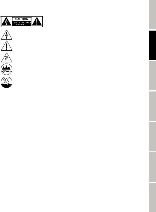
CAUTION:
To reduce the risk of electric shock, do not remove cover (or back). There are no user serviceable parts inside. Maintenance and repairs should be exclusively carried out by qualified service personnel.
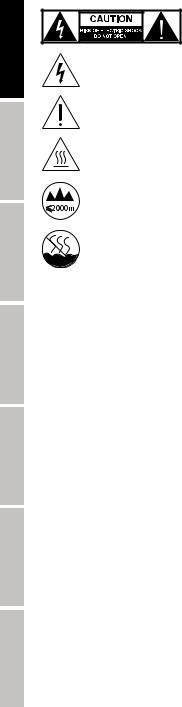
The warning triangle with lightning symbol indicates dangerous uninsulated voltage inside the unit, which may cause an electrical shock.
The warning triangle with exclamation mark indicates important operating and maintenance instructions.
Warning! This symbol indicates a hot surface. Certain parts of the housing can become hot during operation. After use, wait for a cool-down period of at least 10 minutes before handling or transporting the device.
Warning! This device is designed for use below 2000 metres in altitude.
Warning! This product is not intended for use in tropical climates.
CAUTION! HIGH VOLUMES IN AUDIO PRODUCTS!
This device is meant for professional use. Therefore, commercial use of this equipment is subject to the respectively applicable national accident prevention rules and regulations. As a manufacturer, Adam Hall is obligated to notify you formally about the existence of potential health risks. Hearing damage due to high volume and prolonged exposure: When in use, this product is capable of producing high sound-pressure levels (SPL) that can lead to irreversible hearing damage in performers, employees, and audience members. For this reason, avoid prolonged exposure to volumes in excess of 90 dB.
INTRODUCTION
MINI MOVING HEAD 30W
CLNS300
CONTROL FUNCTIONS
5-channel, 9-channel, 11-channel DMX control IR remote control
Master / Slave mode Standalone Function
FEATURES
Mini Moving Head with 30 W CW LED, Colour wheel with 7 colours plus open, Gobo wheel with 7 gobos plus open, 540° PAN and 230° TILT movement, 3 DMX modes, DMX 512 control, Master/Slave operation, Standalone programs, Music control via built-in microphone, universal mounting options, rubber feet, safety eyelet and 1 omega bracket included, operating voltage 100 - 240 V AC / 50 - 60 Hz, power consumption 100 W.
OPERATION
The Cameo NANOSPOT300 is a DMX 512 controllable Mini LED Moving Head and can be operated as Standalone device, in Master/Slave mode, via IR remote control and Music control.
4
CONNECTIONS, CONTROLS AND INDICATORS
ENGLISH
2 |
3 |
1 |
4 |
DEUTSCH
8
5
 7 6
7 6
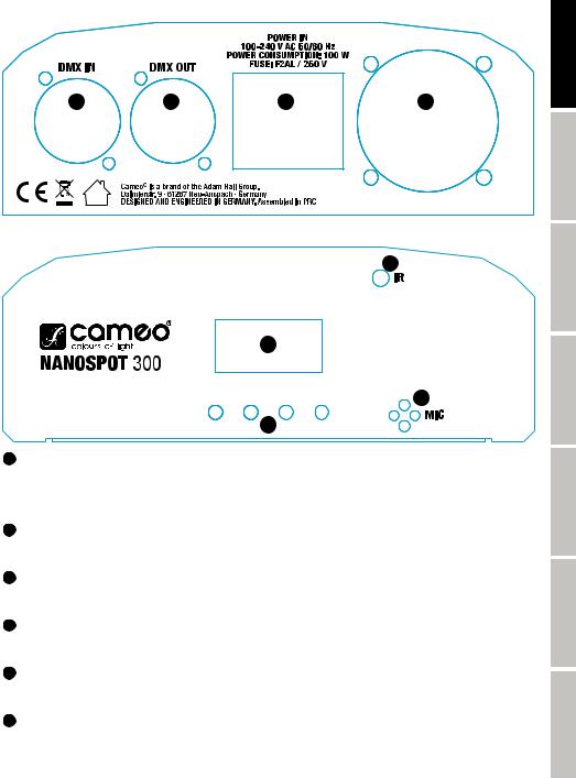
1 POWER IN
IEC power socket with built-in fuse holder. An appropriate power cord is included in the delivery.
IMPORTANT INFORMATION: Always replace the fuse only with a fuse of the same type with the same rating (printed on the device). If the fuse blows repeatedly, please contact an authorised service centre.
2 DMX IN
3-pin male XLR socket for connection of a DMX controller (e.g. DMX console).
3 DMX OUT
3-pin female XLR socket for looping through the DMX control signal.
4 HOUSING FAN
To prevent overheating of the device, make sure that the fan is not covered and that air can circulate freely.
5 LED DISPLAY
The four-digit LED display indicates the operating mode and other system information.
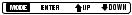
6 CONTROL BUTTONS
MODE: To access a higher level in the menu structure and return to the main display. ENTER: Confirm program selection and value changes.
UP and DOWN: Selecting an operating mode, system settings and programs, e.g. changing the program speed and DMX address.
FRANCAIS
ESPAÑOL
POLSKI
ITALIANO
DMX
5
ENGLISH
FRANCAIS DEUTSCH
ESPAÑOL
POLSKI
ITALIANO
DMX
7 MIC
Microphone for music control mode.
8 INFRARED SENSOR
In order to easily control the Moving Head via the supplied remote control, be sure to position the infrared interface of the remote control in direct visual contact, at a maximum distance of 5 m from the infrared interface of the spotlight.
NOTE: The lens for focussing the projection at different distances is located in the projection head of the Moving Head. The knurled frame provides for a better grip (clockwise rotation = remote range, counter-clockwise rotation = close range).
OPERATION
When the spotlight is properly connected to the mains, the motors are reset (Display = “InIt”). Within a few seconds, the spotlight is ready for use and changes to the mode that was previously selected.
SELECTING THE DMX STARTING ADDRESS AND DMX MODE
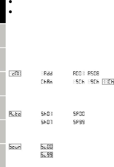
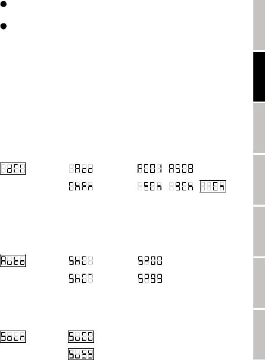
Press the MODE button repeatedly until “dMX”, “PrEF”, “SLAV”, “Soun”, or “Auto” appears on the display. Now use the UP and DOWN buttons to select the “dMX” menu item and confirm by pressing ENTER. “Add” now appears on the display and by pressing ENTER once more, you can select the DMX start address as desired using the UP and DOWN switches (A001 - A508). After confirming with ENTER, “SAVE” is briefly shown on the display. To set the DMX operating mode, select the menu item “dMX”, press ENTER and then use the UP and DOWN buttons to select the menu item “ChAn”. Press ENTER and use the UP and DOWN buttons to select the desired DMX mode (5Ch, 9Ch, 11Ch). After confirming with ENTER, “SAVE” is briefly shown on the display. The synchronous control of multiple spotlights (same model) through
a DMX control unit (e.g. DMX console) can be achieved by assigning the spotlights to an identical DMX start address and DMX mode and connecting them using DMX cables.
-> ENTER -> |
|
-> ENTER -> |
|
– |
|
|
UP/DOWN |
|
UP/DOWN |
|
|
|
|
<- MODE |
|
<- MODE |
|
|
|
|
|
|
-> ENTER -> |
|
/ |
|
/ |
|
|
|
|
|||
|
|
UP/DOWN |
|
|
||
|
|
<- MODE |
|
|
|
|
AUTOMATIC CONTROL MODE (AUTO)
Select one of the 7 different Auto programs (Sh01 - Sh07) and their speed (SP00 - SP99). Press the MODE button repeatedly until “dMX”, “PrEF”, “SLAV”, “Soun”, or “Auto” appears on the display. Now use the UP and DOWN buttons to select the “Auto” menu item and confirm by pressing ENTER (“SAVE” is briefly displayed on the display). Press twice on ENTER, then use the UP and DOWN buttons to select one of the 7 Auto programs (the last 2 digits of the display will flash). After confirming with ENTER, “SAVE” is briefly shown on the display. Now the activated program will be shown on the display and you can use the UP and DOWN buttons to select the desired speed in the menu item. Now, press ENTER (the last two digits on the display will flash) and using the UP and DOWN buttons, select the speed from SP00 to SP99. After confirming with ENTER, “SAVE” is briefly displayed on the display.
-> ENTER -> |
|
-> ENTER -> |
UP/DOWN |
|
UP/DOWN |
|
|
ENTER |
|
<- MODE |
|
<- MODE |
UP/DOWN |
|
|
– |
|
|
– |
|
|
|
|
|
MUSIC CONTROL (SOUND)
Select the Music control mode, to control the Moving Head via the built-in microphone (bass pulses). Press the MODE button repeatedly until “dMX”, “PrEF”, “SLAV”, “Soun”, or “Auto” appears on the display. Now use the UP and DOWN buttons to select the “Soun” menu item and confirm by pressing ENTER (“SAVE” is briefly displayed on the display). Press ENTER again to select the sensitivity with which the spotlight responds to sounds (Su00 - Su99). After confirming with ENTER, “SAVE” is briefly shown on the display.
-> ENTER -> UP/DOWN
<- MODE
–
SLAVE MODE
Press the MODE button repeatedly until “dMX”, “PrEF”, “SLAV”, “Soun”, or “Auto” appears on the display. Use the UP and DOWN buttons to select the “SLAV” menu item and confirm by pressing ENTER. Use the UP and DOWN buttons to select “YES” and confirm by pressing ENTER
6
(“SAVE” is briefly displayed on the display). Connect the slave and the master unit (same model) with a DMX cable and activate one of the standalone modes on the master unit. Now the slave unit follows the master unit.
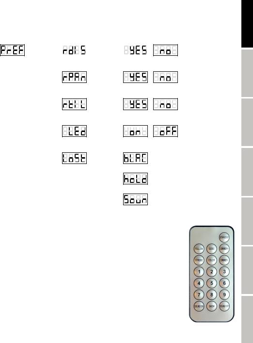
SYSTEM SETTINGS
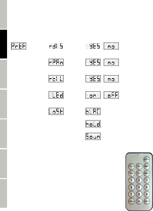
To adjust system settings, press the MODE button repeatedly until “dMX”, “PrEF”, “SLAV”, “Soun”, or “Auto” appears on the display. Use the UP and DOWN buttons to select the “PrEF” menu item and confirm by pressing ENTER. You can now select and adjust one of the following menu items using the UP and DOWN buttons (confirm with ENTER, exit with MODE):
-> ENTER -> |
|
-> ENTER -> |
UP/DOWN |
|
/ |
UP/DOWN |
|
|
|
||
<- MODE |
|
<- MODE |
|
|
|
YES = LED display Is rotated by180° (overhead mounting)
-> ENTER ->
UP/DOWN /
<- MODE
YES = reversal of
PAN direction
-> ENTER ->
UP/DOWN /
<- MODE
YES = reversal of
TILT direction
-> ENTER -> 


 UP/DOWN /
<- MODE
on = display always on off = display goes off after
approx. 20 seconds of inactivity
-> ENTER ->
UP/DOWN
<- MODE
With this menu item, you can define which operating mode should be enabled when in the DMX mode,
the DMX signal is interrupted.
(blackout)
(last command)
(Music control)
IR REMOTE CONTROL
In order to easily control the Moving Head via the supplied remote control, be sure to position the infrared interface of the remote control in direct visual contact, at a maximum distance of 5 m from the infrared interface of the spotlight and follow the sequence of operations (1. “STAND BY”, 2. “FULL ON”).
STAND BY
Press on “STAND BY”, to control the Moving Head in the IR remote control mode. The LED display now shows “StoP” and the head moves in the upright position.
FULL ON
After the Moving Head has been brought into the IR remote control mode (see section “STAND BY”), press “FULL ON” to switch on the LED illumination.
ENGLISH
FRANCAIS DEUTSCH
ESPAÑOL
POLSKI
ITALIANO
DMX
7

ENGLISH
FRANCAIS DEUTSCH
ESPAÑOL
POLSKI
ITALIANO
DMX
GOBO
As soon as you press on “GOBO”, one of the 7 gobos plus open can now be selected using the number keys 1 to 8 (1 = open).
COLOR
As soon as you press on “COLOR”, one of the 7 colour filters plus open can now be selected using the number keys 1 to 8 (1 = open).
STROBE
To activate the stroboscope effect, press on “STROBE” and then select the speed of the strobe using the number keys 1 to 9 (1 = strobe disabled, 2 = slowest flash frequency, 9 = fastest flash frequency).
DIMMER+
Increase the brightness level by pressing “DIMMER+”.
DIMMER-
Decrease the brightness level by pressing “DIMMER-”.
1 - 9
The number keys 1 to 9 are used to select the different gobos, colour filters, strobe speed and internal programs.
SOUND ON
While one of the 7 internal show programs is selected, the Music control mode can be activated by pressing “SOUND ON”. Now the selected program is controlled via the built-in microphone and follows the beat of the music (bass pulses).
SOUND OFF
Press “SOUND OFF” to disable the Music control mode.
SHOW
Press “SHOW” to activate one of the 7 different Show programs using the number keys 1 to 7.
Press “STAND BY” to disable the IR remote control mode. The spotlight now changes to the mode that was previously selected.
SETTING UP AND MOUNTING
Thanks to the integrated rubber feet, the spotlight can be placed in a suitable location on the stage floor etc.
Mounting on a truss is performed with the help of the supplied omega mounting bracket; secure the device with a suitable safety rope to
the safety screw eye. Fix both firmly onto the base plate of the spotlight, suitable screws are included in the delivery. NOTE: Overhead installation should only be carried out by trained personnel.
8
DMX TECHNOLOGY
DMX-512
DMX (Digital Multiplex) is the designation for a universal transmission protocol for communications between corresponding devices and controllers. A DMX controller sends DMX data to the connected DMX device(s). The DMX data is always transmitted as a serial data stream that is forwarded from one connected device to the next via the "DMX IN" and "DMX OUT" connectors (XLR plug-type connectors) that are found on every DMX-capable device, provided the maximum number of devices does not exceed 32 units. The last device in the chain needs to be equipped with a terminator (terminating resistor).
DMX CONNECTION
DMX is the common "language" via which a very wide range of types and models of equipment from various manufacturers can be connected with one another and controlled via a central controller, provided that all of the devices and the controller are DMX
compatible. For optimum data transmission, it is necessary to keep the connecting cables between the individual devices as short as possible. The order in which the devices are integrated in the DMX network has no influence on the addresses. Thus the device with the DMX address 1 can be located at any position in the (serial) DMX chain: at the beginning, at the end or somewhere in the middle. If the DMX address 1 is assigned to a device, the controller "knows" that it should send all data allocated to address 1 to this device regardless of its position in the DMX network.
SERIAL CONNECTION OF MULTIPLE LIGHTS
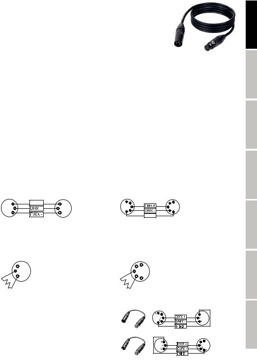
1.Connect the male XLR connector (3-pin or 5-pin) of the DMX cable to the DMX output (female XLR socket) of the first DMX device (e.g. DMX-Controller).
2.Connect the female 3-pin XLR connector of the DMX cable connected to the first projector to the DMX input (male 3-pin socket) of the next DMX device. In the same way, connect the DMX output of this device to the DMX input of the next device and repeat until all devices have been connected. Please note that as a rule, DMX devices are connected in series and connections cannot be shared without active splitters. The maximum number of DMX devices in a DMX chain should not exceed 32 units.
The Adam Hall 3 STAR, 4 STAR, and 5 STAR product ranges include an extensive selection of suitable cables.
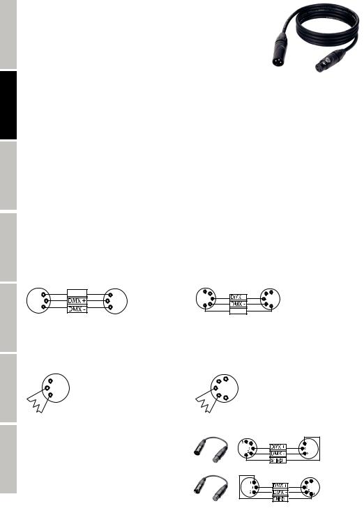
DMX CABLES
When fabricating your own cables, always observe the illustrations on this page. Never connect the shielding of the cable to the ground contact of the plug, and always make certain that the shielding does not come into contact with the housing of the XLR plug. If the shielding is connected to the ground, this can lead to short-circuiting and system malfunctions.
Pin Assignment |
|
|
|
|
|
|
DMX cable with 3-pin XLR connectors: |
DMX cable with 5-pin XLR connectors (pin 4 and 5 are not used): |
|||||
1 |
Shield |
1 |
5 |
4 |
4 |
5 |
3 |
|
3 |
|
3 |
3 |
|
|
1 |
2 |
2 |
|
||
2 |
|
2 |
1 |
|||
|
|
|
|
|
Shield |
|
DMX TERMINATORS (TERMINATING RESISTORS)
To prevent system errors, the last device in a DMX chain needs to be equipped with a terminating resistor (120 ohm, 1/4 Watt). 3-pin XLR connector with a terminating resistor: K3DMXT3
5-pin XLR connector with a terminating resistor: K3DMXT5
Pin Assignment |
|
|
|
3-pin XLR connector: |
5-pin XLR connector: |
||
|
1 |
4 |
5 |
3 |
|
|
|
2 |
32 |
1 |
|
|
|
|
|
DMX ADAPTER
The combination of DMX devices with 3-pin connectors and DMX devices with 5-pin connectors in a DMX chain is possible with suitable adapters.
Pin Assignment
DMX Adapter 5-pin XLR male to 3-pin XLR female: K3DGF0020
Pins 4 and 5 are not used.
Pin Assignment
DMX Adapter 3-pin XLR male to 5-pin XLR female: K3DHM0020
Pins 4 and 5 are not used.
9
ENGLISH
FRANCAIS DEUTSCH
ESPAÑOL
POLSKI
ITALIANO
DMX
ENGLISH
FRANCAIS DEUTSCH
ESPAÑOL
POLSKI
ITALIANO
DMX
TECHNICAL SPECIFICATIONS
Model Name: |
CLNS300 |
Product Type: |
LED moving head |
Type: |
spot |
Colour Spectrum: |
W |
Number of LEDs: |
1 |
LED Type: |
30 W |
Beam Angle: |
13° |
DMX Input: |
3-pin XLR male |
DMX Output: |
3-pin XLR female |
DMX Mode: |
5-channel, 9-channel, 11-channel |
DMX Functions: |
Pan/Tilt, Pan/Tilt fine, Colour Wheel, Gobo Wheel, Motor Speed, Auto Programs, Music |
|
Control, Stroboscope, Dimmer |
Standalone Functions: |
Auto Programs, Music Control, Master/Slave mode |
Control: |
DMX512, IR remote control |
Controls: |
Mode, Enter, Up, Down |
Indicators: |
4-digit LED display |
PAN Angle: |
540° |
TILT Angle: |
230° |
Operating Voltage: |
100 - 240 V AC / 50 - 60 Hz |
Power Consumption: |
100 W |
Light Output: |
650 lm |
Illuminance (@ 1 m): |
24,500 lx |
Power Connector: |
IEC power socket |
Fuse: |
F2AL / 250 V fuse (5 x 20 mm). |
Temperature (during operation): |
0°C - 40°C |
Relative Humidity: |
< 85% non-condensing |
Housing Material: |
metal, ABS |
Housing Colour: |
black |
Housing Cooling: |
fan |
Dimensions (W x H x D, excluding bracket): |
165 x 280 x 155 mm |
Weight: |
3 kg |
Other Features: |
power cable, IR remote control, safety screw eye and omega mounting bracket |
|
included |
10
MANUFACTURER´S DECLARATIONS
MANUFACTURER‘S WARRANTY & LIMITATIONS OF LIABILITY
You can find our current warranty conditions and limitations of liability at: http://www.adamhall.com/media/shop/downloads/documents/ manufacturersdeclarations.pdf. To request warranty service for a product, please contact Adam Hall GmbH, Daimler Straße 9, 61267 Neu Anspach / Email: Info@adamhall.com / +49 (0)6081 / 9419-0.
CORRECT DISPOSAL OF THIS PRODUCT
(valid in the European Union and other European countries with a differentiated waste collection system)
 This symbol on the product, or on its documents indicates that the device may not be treated as household waste. This is to avoid environmental damage or personal injury due to uncontrolled waste disposal. Please dispose of this product separately from other waste and have it recycled to promote sustainable economic activity. Household users should contact either the retailer where they purchased this product, or their local government office, for details on where and how they can recycle this item in an environmentally friendly manner. Business users should contact their supplier and check the terms and conditions of the purchase contract. This product should not be mixed with other commercial waste for disposal.
CE Compliance
Adam Hall GmbH states that this product meets the following guidelines (where applicable): R&TTE (1999/5/EC) or RED (2014/53/EU) from June 2017
Low voltage directive (2014/35/EU) EMV directive (2014/30/EU)
RoHS (2011/65/EU)
The complete declaration of conformity can be found at www.adamhall.com. Furthermore, you may also direct your enquiry to info@adamhall.com.
ENGLISH
FRANCAIS DEUTSCH
ESPAÑOL
POLSKI
ITALIANO
DMX
11

ENGLISH
FRANCAIS DEUTSCH
ESPAÑOL
POLSKI
ITALIANO
DMX
DEUTSCH
SIE HABEN DIE RICHTIGE WAHL GETROFFEN!
Dieses Gerät wurde unter hohen Qualitätsanforderungen entwickelt und gefertigt, um viele Jahre einen reibungslosen Betrieb zu gewährleisten. Bitte lesen Sie diese Bedienungsanleitung sorgfältig, damit Sie Ihr neues Produkt von Cameo Light schnell und optimal einsetzen können. Weitere Informationen über Cameo Light erhalten Sie auf unserer Website WWW.CAMEOLIGHT.COM.
SICHERHEITSHINWEISE
1.Lesen Sie diese Anleitung bitte sorgfältig durch.
2.Bewahren Sie alle Informationen und Anleitungen an einem sicheren Ort auf.
3.Befolgen Sie die Anweisungen.
4.Beachten Sie alle Warnhinweise. Entfernen Sie keine Sicherheitshinweise oder andere Informationen vom Gerät.
5.Verwenden Sie das Gerät nur in der vorgesehenen Art und Weise.
6.Verwenden Sie ausschließlich stabile und passende Stative bzw. Befestigungen (bei Festinstallationen). Stellen Sie sicher, dass Wandhalterungen ordnungsgemäß installiert und gesichert sind. Stellen Sie sicher, dass das Gerät sicher installiert ist und nicht herunterfallen kann.
7.Beachten Sie bei der Installation die für Ihr Land geltenden Sicherheitsvorschriften.
8.Installieren und betreiben Sie das Gerät nicht in der Nähe von Heizkörpern, Wärmespeichern, Öfen oder sonstigen Wärmequellen. Sorgen Sie dafür, dass das Gerät immer so installiert ist, dass es ausreichend gekühlt wird und nicht überhitzen kann.
9.Platzieren Sie keine Zündquellen wie z.B. brennende Kerzen auf dem Gerät.
10.Lüftungsschlitze dürfen nicht blockiert werden.
11.Das Gerät wurde ausschließlich für die Verwendung in Innenräumen entwickelt, betreiben Sie das Gerät nicht in unmittelbarer Nähe von Wasser (gilt nicht für spezielle Outdoor Geräte - beachten Sie in diesem Fall bitte die im Folgenden vermerkten Sonderhinweise). Bringen Sie das Gerät nicht mit brennbaren Materialien, Flüssigkeiten oder Gasen in Berührung.
12.Sorgen Sie dafür, dass kein Tropfoder Spritzwasser in das Gerät eindringen kann. Stellen Sie keine mit Flüssigkeit gefüllten Behältnisse wie Vasen oder Trinkgefäße auf das Gerät.
13.Sorgen Sie dafür, dass keine Gegenstände in das Gerät fallen können.
14.Betreiben Sie das Gerät nur mit dem vom Hersteller empfohlenen und vorgesehenen Zubehör.
15.Öffnen Sie das Gerät nicht und verändern Sie es nicht.
16.Überprüfen Sie nach dem Anschluss des Geräts alle Kabelwege, um Schäden oder Unfälle, z. B. durch Stolperfallen zu vermeiden.
17.Achten Sie beim Transport darauf, dass das Gerät nicht herunterfallen und dabei möglicherweise Sachund Personenschäden verursachen kann.
18.Wenn Ihr Gerät nicht mehr ordnungsgemäß funktioniert, Flüssigkeiten oder Gegenstände in das Geräteinnere gelangt sind, oder das Gerät anderweitig beschädigt wurde, schalten Sie es sofort aus und trennen es von der Netzsteckdose (sofern es sich um ein aktives Gerät handelt). Dieses Gerät darf nur von autorisiertem Fachpersonal repariert werden.
19.Verwenden Sie zur Reinigung des Geräts ein trockenes Tuch.
20.Beachten Sie alle in Ihrem Land geltenden Entsorgungsgesetze. Trennen Sie bei der Entsorgung der Verpackung bitte Kunststoff und Papier bzw. Kartonagen voneinander.
21.Kunststoffbeutel müssen außer Reichweite von Kindern aufbewahrt werden.
BEI GERÄTEN MIT NETZANSCHLUSS:
22.ACHTUNG: Wenn das Netzkabel des Geräts mit einem Schutzkontakt ausgestattet ist, muss es an einer Steckdose mit Schutzleiter angeschlossen werden. Deaktivieren Sie niemals den Schutzleiter eines Netzkabels.
23.Schalten Sie das Gerät nicht sofort ein, wenn es starken Temperaturschwankungen ausgesetzt war (beispielsweise nach dem Transport). Feuchtigkeit und Kondensat könnten das Gerät beschädigen. Schalten Sie das Gerät erst ein, wenn es Zimmertemperatur erreicht hat.
24.Bevor Sie das Gerät an die Steckdose anschließen, prüfen Sie zuerst, ob die Spannung und die Frequenz des Stromnetzes mit den auf dem Gerät angegebenen Werten übereinstimmen. Verfügt das Gerät über einen Spannungswahlschalter, schließen Sie das Gerät nur an die Steckdose an, wenn die Gerätewerte mit den Werten des Stromnetzes übereinstimmen. Wenn das mitgelieferte Netzkabel bzw. der mitgelieferte Netzadapter nicht in Ihre Netzsteckdose passt, wenden Sie sich an Ihren Elektriker.
25.Treten Sie nicht auf das Netzkabel. Sorgen Sie dafür, dass spannungsführende Kabel speziell an der Netzbuchse bzw. am Netzadapter und der Gerätebuchse nicht geknickt werden.
26.Achten Sie bei der Verkabelung des Geräts immer darauf, dass das Netzkabel bzw. der Netzadapter stets frei zugänglich ist. Trennen Sie das Gerät stets von der Stromzuführung, wenn das Gerät nicht benutzt wird, oder Sie das Gerät reinigen möchten. Ziehen Sie Netzkabel und Netzadapter immer am Stecker bzw. am Adapter und nicht am Kabel aus der Steckdose. Berühren Sie Netzkabel und Netzadapter niemals mit nassen Händen.
27.Schalten Sie das Gerät möglichst nicht schnell hintereinander ein und aus, da sonst die Lebensdauer des Geräts beeinträchtigt werden könnte.
28.WICHTIGER HINWEIS: Ersetzen Sie Sicherungen ausschließlich durch Sicherungen des gleichen Typs und Wertes. Sollte eine Sicherung wiederholt auslösen, wenden Sie sich bitte an ein autorisiertes Servicezentrum.
29.Um das Gerät vollständig vom Stromnetz zu trennen, entfernen Sie das Netzkabel bzw. den Netzadapter aus der Steckdose.
30.Wenn Ihr Gerät mit einem Volex-Netzanschluss bestückt ist, muss der passende Volex-Gerätestecker entsperrt werden, bevor er entfernt werden kann. Das bedeutet aber auch, dass das Gerät durch ein Ziehen am Netzkabel verrutschen und herunterfallen kann, wodurch Personen verletzt werden und/oder andere Schäden auftreten können. Verlegen Sie Ihre Kabel daher immer sorgfältig.
31.Entfernen Sie Netzkabel und Netzadapter aus der Steckdose bei Gefahr eines Blitzschlags oder wenn Sie das Gerät länger nicht verwenden.
32.Das Gerät darf nur im spannungsfreien Zustand (Trennung des Netzsteckers vom Stromnetz) installiert werden.
33.Staub und andere Ablagerungen im Inneren des Geräts können es beschädigen. Das Gerät sollte je nach Umgebungsbedingungen (Staub, Nikotin, Nebel etc.) regelmäßig von qualifiziertem Fachpersonal gewartet bzw. gesäubert werden (keine Garantieleistung), um Überhitzung und Fehlfunktionen zu vermeiden.
34.Der Abstand zu brennbaren Materialien muss mindestens 0,5 m betragen.
1235. Netzleitungen zur Spannungsversorgung mehrerer Geräte müssen mindestens 1,5 mm² Aderquerschnitt aufweisen. In der EU müssen
die Leitungen H05VV-F, oder gleichartig, entsprechen. Geeignete Leitungen werden von Adam Hall angeboten. Mit diesen Leitungen können Sie mehrere Geräte über den Power out Anschluss mit dem Power IN Anschluss eines weiteren Gerätes verbinden. Beachten Sie, dass die gesamte Stromaufnahme aller angeschlossenen Geräte den vorgegebenen Wert nicht überschreitet (Aufdruck auf dem Gerät). Achten Sie darauf, Netzleitungen so kurz wie möglich zu halten.
ACHTUNG
Entfernen Sie niemals die Abdeckung, da sonst das Risiko eines elektrischen Schlages besteht. Im

 Inneren des Geräts befinden sich keine Teile, die vom Bediener repariert oder gewartet werden können.
  Lassen Sie Wartung und Reparaturen ausschließlich von qualifiziertem Servicepersonal durchführen.
Das gleichseitige Dreieck mit Blitzsymbol warnt vor nichtisolierten, gefährlichen Spannungen im Geräteinneren, die einen elektrischen Schlag verursachen können.
Das gleichseitige Dreieck mit Ausrufungszeichen kennzeichnet wichtige Bedienungsund Wartungshinweise.
Warnung! Dieses Symbol kennzeichnet heiße Oberflächen. Während des Betriebs können bestimmte Teile des Gehäuses heiß werden. Berühren oder transportieren Sie das Gerät nach einem Einsatz erst nach einer Abkühlzeit von mindestens 10 Minuten.
Warnung! Dieses Gerät ist für eine Nutzung bis zu einer Höhe von maximal 2000 Metern über dem Meeresspiegel bestimmt.
Warnung! Dieses Gerät ist nicht für den Einsatz in tropischen Klimazonen bestimmt.
VORSICHT! WICHTIGE HINWEISE IN BEZUG AUF LICHT-PRODUKTE!
1.Das Produkt ist für den professionellen Einsatz im Bereich der Veranstaltungstechnik entwickelt worden und ist nicht für die Raumbeleuchtung in Haushalten geeignet.
2.Blicken Sie niemals, auch nicht kurzzeitig, direkt in den Lichtstrahl.
3.Blicken Sie niemals mit optischen Geräten wie Vergrößerungsgläsern in den Lichtstrahl.
4.Stroboskopeffekte können unter Umständen bei empfindlichen Menschen epileptische Anfälle auslösen! Epilepsiekranke Menschen sollten daher unbedingt Orte meiden, an denen Stroboskope eingesetzt werden.
EINFÜHRUNG
MINI MOVING HEAD 30W
CLNS300
STEUERUNGSFUNKTIONEN
5-Kanal, 9-Kanal, 11-Kanal DMX-Steuerung
IR-Fernbedienung
Master / Slave Betrieb
Standalone Funktion
EIGENSCHAFTEN
Mini Moving Head mit 30W CW LED, Farbrad mit 7 Farben plus offen, Goborad mit 7 Gobos plus offen, 540° PAN und 230° TILT Bewegung, 3 DMX-Modi, DMX-512 Steuerung, Master / Slave Betrieb, Standalone Programme, Musiksteuerung über eingebautes Mikrofon, Universelle Montagemöglichkeiten, Gummifüße, Safety Schrauböse und 1 Omega-Bügel inklusive, Betriebsspannung 100V - 240V AC / 50 - 60Hz, Leistungsaufnahme 100W.
BEDIENUNG
Der Cameo NANOSPOT300 ist ein DMX-512-steuerbarer Mini LED Moving Head und läßt sich als Standalone-Gerät, im Master / Slave-Betrieb, per IR-Fernbedienung und Musiksteuerung betreiben.
ENGLISH
FRANCAIS DEUTSCH
ESPAÑOL
POLSKI
ITALIANO
DMX
13

ANSCHLÜSSE, BEDIENUND ANZEIGEELEMENTE
ENGLISH
2 |
3 |
1 |
4 |
DEUTSCH
FRANCAIS
8
ESPAÑOL
POLSKI
ITALIANO
DMX
5
7
6
1 POWER IN
IEC Netzbuchse mit integriertem Sicherungshalter. Ein geeignetes Netzkabel befindet sich im Lieferumfang.
WICHTIGER HINWEIS: Ersetzen Sie die Sicherung ausschließlich durch eine Sicherung des gleichen Typs und mit gleichen Werten entsprechend des Aufdrucks auf dem Gerät! Sollte die Sicherung wiederholt auslösen, wenden Sie sich bitte an ein autorisiertes Servicezentrum.
2 DMX IN
Männliche 3-Pol XLR-Buchse zum Anschließen eines DMX-Kontrollgeräts (z.B. DMX-Pult).
3 DMX OUT
Weibliche 3-Pol XLR-Buchse zum Weiterleiten des DMX-Steuersignals.
4 GEHÄUSELÜFTER
Um Überhitzung des Geräts zu vermeiden, achten Sie darauf, dass der Lüfter nicht abgedeckt wird und Luft ungehindert zirkulieren kann.
5 LED DISPLAY
Das vierstellige LED-Display zeigt die Betriebsart und weitere Systeminformationen an.
6 BEDIENTASTEN
MODE: In der Menüstruktur eine Ebene höher gelangen, bis zur Hauptanzeige. ENTER: Bestätigen von Programmauswahl und Wertänderungen.
UP und DOWN: Auswahl einer Betriebsart, von Systemeinstellungen und Programmen, z.B. ändern von Programmgeschwindigkeit und 14DMX-Adresse.
7 MIC
Mikrofon für die Betriebsart Musiksteuerung.
8 INFRAROTSENSOR
Um den Moving Head bequem über die mitgelieferte IR-Fernbedienung steuern zu können, achten Sie darauf, die Infrarot-Schnittstelle der Fernbedienung in direktem Sichtkontakt in einem Abstand von bis zu ca. 5m zur Infrarot-Schnittstelle des Scheinwerfers zu positionieren.
HINWEIS: Im Projektionskopf des Moving Heads befindet sich die Linse zum Fokussieren der Projektion in unterschiedlichen Entfernungen. Für eine verbesserte Griffigkeit sorgt eine gerändelte Fassung (Drehung im Uhrzeigersinn = Fernbereich, Drehung gegen den Uhrzeigersinn = Nahbereich).
BEDIENUNG
Sobald der Scheinwerfer korrekt am Stromnetz angeschlossen ist, erfolgt das Zurücksetzen der Motoren (Display = „InIt“). Nach wenigen Sekunden ist der Scheinwerfer betriebsbereit und wechselt in die Betriebsart, die zuvor angewählt war.
DMX-STARTADRESSE UND DMX-BETRIEBSART EINSTELLEN
Drücken Sie die MODE-Taste so oft, bis im Display einer der Menüpunkte „dMX“, „PrEF“, „SLAV“, „Soun“, oder „Auto“ angezeigt wird. Wählen Sie nun mit Hilfe der Tasten UP und DOWN den Menüpunkt „dMX“ aus und drücken auf ENTER. Im Display wird jetzt „Add“ angezeigt und Sie können durch nochmaliges Drücken auf ENTER die DMX-Startadresse anzeigen lassen und sie mit Hilfe der Tasten UP und DOWN wunschgemäß einstellen (A001 - A508). Nach dem Bestätigen mit ENTER wird im Display für kurze Zeit „SAVE“ angezeigt. Die DMX-Betriebsart stellen Sie ein, indem Sie den Menüpunkt „dMX“ auswählen, auf ENTER drücken und nun mit UP und DOWN den Menüpunkt „ChAn“ auswählen. Drücken Sie auf ENTER und wählen nun mit Hilfe der Tasten UP und DOWN die gewünschte DMX-Betriebsart aus (5Ch, 9Ch, 11Ch). Nach dem Bestätigen mit ENTER wird im Display für kurze Zeit „SAVE“ angezeigt. Die synchrone Ansteuerung mehrerer Scheinwerfer des gleichen Modells durch ein DMX-Steuergerät (z.B. DMX-Pult) erreichen Sie, indem Sie die Scheinwerfer auf eine identische DMX-Startadresse und die gleiche DMX-Betriebsart einstellen und mit Hilfe von DMX-Kabeln verbinden.
-> ENTER -> |
|
-> ENTER -> |
|
– |
|
|
UP/DOWN |
|
UP/DOWN |
|
|
|
|
<- MODE |
|
<- MODE |
|
|
|
|
|
|
-> ENTER -> |
|
/ |
|
/ |
|
|
|
|
|||
|
|
UP/DOWN |
|
|
||
|
|
<- MODE |
|
|
|
|
AUTOMATISCHE STEUERUNG (AUTO)
Wählen Sie eines der 7 verschiedenen Auto-Programme (Sh01 - Sh07) und deren Laufgeschwindigkeit aus (SP00 - SP99). Drücken Sie die MODE-Taste so oft, bis im Display einer der Menüpunkte „dMX“, „PrEF“, „SLAV“, „Soun“, oder „Auto“ angezeigt wird. Wählen Sie nun mit Hilfe der Tasten UP und DOWN den Menüpunkt „Auto“ aus und drücken auf ENTER (im Display wird für kurze Zeit „SAVE“ angezeigt). Drücken Sie zwei mal auf ENTER, um nun mit Hilfe der Tasten UP und DOWN aus den 7 Auto-Programmen wählen zu können (die letzten 2 Ziffern des Displays blinken). Nach dem Bestätigen mit ENTER wird im Display für kurze Zeit „SAVE“ angezeigt. Nun wird im Display das aktivierte Programm angezeigt und Sie können mit Hilfe der Tasten UP und DOWN den Menüpunkt für die Laufgeschwindigkeit auswählen. Drücken Sie auf ENTER (die letzten 2 Ziffern des Displays blinken) und stellen die Geschwindigkeit mit Hilfe der Tasten UP und DOWN von SP00 bis SP99 ein. Nach dem Bestätigen mit ENTER, wird im Display für kurze Zeit „SAVE“ angezeigt.
-> ENTER -> |
|
-> ENTER -> |
UP/DOWN |
|
UP/DOWN |
|
|
ENTER |
|
<- MODE |
|
<- MODE |
UP/DOWN |
|
|
– |
|
|
– |
|
|
|
|
|
MUSIKSTEUERUNG (SOUND)
Wählen Sie die Betriebsart Musiksteuerung, um den Moving Head über das integrierte Mikrofon steuern zu lassen (Bassimpulse). Drücken Sie die MODE-Taste so oft, bis im Display einer der Menüpunkte „dMX“, „PrEF“, „SLAV“, „Soun“, oder „Auto“ angezeigt wird. Wählen
Sie nun mit Hilfe der Tasten UP und DOWN den Menüpunkt „Soun“ aus und drücken auf ENTER (im Display wird für kurze Zeit „SAVE“ angezeigt). Drücken Sie abermals auf ENTER, um die Empfindlichkeit, mit der der Scheinwerfer auf Geräusche reagieren soll, wunschgemäß einzustellen (Su00 - Su99). Nach dem Bestätigen mit ENTER wird im Display für kurze Zeit „SAVE“ angezeigt.
-> ENTER -> UP/DOWN
<- MODE
–
ENGLISH
FRANCAIS DEUTSCH
ESPAÑOL
POLSKI
ITALIANO
DMX
15
ENGLISH
FRANCAIS DEUTSCH
ESPAÑOL
POLSKI
ITALIANO
DMX
SLAVE-BETRIEB
Drücken Sie die MODE-Taste so oft, bis im Display einer der Menüpunkte „dMX“, „PrEF“, „SLAV“, „Soun“, oder „Auto“ angezeigt wird. Wählen Sie mit Hilfe der Tasten UP und DOWN den Menüpunkt „SLAV“ aus und drücken auf ENTER. Nutzen Sie die Tasten UP und DOWN um nun „YES“ auszuwählen und bestätigen mit ENTER (im Display wird für kurze Zeit „SAVE“ angezeigt). Verbinden Sie die Slaveund die Master-Einheit (gleiches Modell) mit Hilfe eines DMX-Kabels und aktivieren in der Master-Einheit eine der Standalone Betriebsarten. Nun folgt die Slave-Einheit der Master-Einheit.
SYSTEMEINSTELLUNGEN
Um Systemeinstellungen vornehmen zu können, drücken Sie die MODE-Taste so oft, bis im Display einer der Menüpunkte „dMX“, „PrEF“, „SLAV“, „Soun“, oder „Auto“ angezeigt wird. Wählen Sie mit Hilfe der Tasten UP und DOWN den Menüpunkt „PrEF“ aus und drücken auf ENTER. Sie können nun mit Hilfe der UP und DOWN Tasten einen der folgenden Menüpunkte auswählen und bearbeiten (bestätigen mit ENTER, verlassen mit MODE):
-> ENTER -> |
|
-> ENTER -> |
UP/DOWN |
|
/ |
UP/DOWN |
|
|
|
||
<- MODE |
|
<- MODE |
|
|
|
YES = Display-Anzeige wird um 180° gedreht (Überkopf-Montage)
-> ENTER ->
UP/DOWN /
<- MODE
YES = Umkehrung der
PAN Bewegungsrichtung
-> ENTER ->
UP/DOWN /
<- MODE
YES = Umkehrung der
TILT Bewegungsrichtung
-> ENTER -> 


 UP/DOWN /
<- MODE
on = Display permanent an off = Display erlischt nach
ca. 20 Sekunden Inaktivität
-> ENTER ->
UP/DOWN
<- MODE
Mit Hilfe dieses Menüpunktes definieren Sie, welcher Betriebszustand aktiviert werden soll, wenn in der DMX-Betriebsart das DMX-Signal unterbrochen wird.
(blackout)
(letzter DMX-Befehl)
(Musiksteuerung)
IR FERNBEDIENUNG
Um den Moving Head bequem über die mitgelieferte IR-Fernbedienung steuern zu können, achten Sie darauf, die Infrarot-Schnittstelle der Fernbedienung in direktem Sichtkontakt in einem Abstand von bis zu ca. 5m zur Infrarot-Schnittstelle des Scheinwerfers zu positionieren und befolgen bitte die Reihenfolge der Bedienschritte (1. „STAND BY“, 2. „FULL ON“).
STAND BY
Drücken Sie auf „STAND BY“, um den Moving Head in die Betriebsart IR-Fernsteuerung zu bringen. Das LED-Display zeigt nun „StoP“ und der Kopf bewegt sich in die aufrechte Position.
FULL ON
Nachdem der Moving Head in die Betriebsart IR-Fernsteuerung gebracht wurde (siehe Punkt „STAND BY“), drücken Sie auf „FULL ON“, um die Beleuchtungs-LED einzuschalten.
16

GOBO
Sobald Sie auf „GOBO“ drücken, kann nun eines der 7 Gobos plus offen mit Hilfe der Nummerntasten 1 bis 8 ausgewählt werden (1 = offen).
COLOR
Drücken Sie auf „COLOR“, um einen der 7 Farbfilter plus offen mit Hilfe der Nummerntasten 1 bis 8 auszuwählen (1 = offen).
STROBE
Zum aktivieren des Stroboskop-Effekts drücken Sie auf „STROBE“ und wählen dann mit Hilfe der Nummerntasten 1 bis 9 die Stroboskop-Geschwindigkeit aus (1 = Stroboskop deaktiviert, 2 = langsamste Blitzfrequenz, 9 = schnellste Blitzfrequenz).
DIMMER+
Erhöhen Sie die Helligkeit, indem Sie auf „DIMMER+“ drücken.
DIMMER-
Verringern Sie die Helligkeit, indem Sie auf „DIMMER-“ drücken.
1 - 9
Die Nummerntasten 1 bis 9 dienen dazu, die verschiedenen Gobos, die Farbfilter, die Stroboskop-Geschwindigkeit und die internen Programme auszuwählen.
SOUND ON
Während eines der 7 internen Show-Programme ausgewählt ist, kann durch Drücken auf „SOUND ON“ die Betriebsart Musiksteuerung aktiviert werden. Das ausgewählte Programm wird nun über das eingebaute Mikrofon gesteuert und folgt dem Takt der Musik (Bassimpulse).
SOUND OFF
Zum Deaktivieren der Betriebsart Musiksteuerung, drücken Sie auf „SOUND OFF“.
SHOW
Drücken Sie auf „SHOW“, um eines der 7 verschiedenen Show-Programme mit Hilfe der Nummerntasten 1 bis 7 zu aktivieren.
Zum Verlassen der Betriebsart IR-Fernbedienung, drücken Sie abermals auf „STAND BY“. Der Scheinwerfer wechselt nun in die Betriebsart, die zuvor aktiviert war.
AUFSTELLUNG UND MONTAGE
Dank der integrierten Gummifüße kann der Scheinwerfer an einer geeigneten Stelle auf den Bühnenboden etc. gestellt werden.
Die Montage an einer Traverse erfolgt mit Hilfe des mitgelieferten Omega-Bügels, sichern Sie das Gerät mit einem geeigneten Sicherungsseil an der Safety Schrauböse. Befestigen Sie Beides fest an der Bodenplatte des Scheinwerfers, geeignete Schrauben befinden sich im Lieferumfang. Hinweis: Überkopfmontage darf nur von dafür ausgebildetem Personal durchgeführt werden.
ENGLISH
FRANCAIS DEUTSCH
ESPAÑOL
POLSKI
ITALIANO
DMX
17
ENGLISH
FRANCAIS DEUTSCH
ESPAÑOL
POLSKI
ITALIANO
DMX
DMX TECHNIK
DMX-512
DMX (Digital Multiplex) ist die Bezeichnung für ein universelles Übertragungsprotokoll für die Kommunikation zwischen entsprechenden Geräten und Controllern. Ein DMX-Controller sendet DMX-Daten an das/die angeschlossene(n) DMX-Gerät(e). Die DMX-Datenübertragung
erfolgt stets als serieller Datenstrom, der über die an jedem DMX-fähigen Gerät vorhandenen DMX INund DMX OUT-Anschlüsse (XLR-Steckverbinder) von einem angeschlossenen
Gerät an das nächste weitergeleitet wird, wobei die maximale Anzahl der Geräte 32 nicht überschreiten darf. Das letzte Gerät der Kette ist mit einem Abschlussstecker (Terminator) zu bestücken.
DMX-VERBINDUNG:
DMX ist die gemeinsame "Sprache", über die sich die unterschiedlichsten Gerätetypen und Modelle verschiedener Hersteller miteinander verkoppeln und über einen zentralen Controller steuern lassen, sofern sämtliche Geräte und der Controller DMXkompatibel sind. Für eine optimale Datenübertragung ist es erforderlich, die Verbindungskabel zwischen den einzelnen Geräten so kurz wie möglich zu halten. Die Reihenfolge, in der die Geräte in das DMX-Netzwerk eingebunden sind, hat keinen Einfluss auf die Adressierung. So kann sich das Gerät mit der DMX-Adresse 1 an einer beliebigen Position in der (seriellen) DMX-Kette befinden, am Anfang, am Ende oder irgendwo in der Mitte. Wird einem Gerät die DMX-Adresse 1 zugewiesen, "weiß" der Controller, dass er alle der Adresse 1 zugeordneten Daten an dieses Gerät senden soll, ungeachtet seiner Position im DMX-Verbund.
SERIELLE VERKOPPLUNG MEHRERER SCHEINWERFER
1.Verbinden Sie den männlichen XLR-Stecker (3-Pol oder 5-Pol) des DMX-Kabels mit dem DMX-Ausgang (weibliche XLR-Buchse) des ersten DMX-Geräts (z.B. DMX-Controller).
2.Verbinden Sie den weibliche XLR-Stecker des an den ersten Scheinwerfer angeschlossenen DMX-Kabels mit dem DMX-Eingang (männliche XLR-Buchse) des nächsten DMX-Geräts. Verbinden Sie den DMX-Ausgang dieses Geräts in der gleichen Weise mit dem DMX-Eingang des nächsten Geräts und so weiter. Bitte beachten Sie, dass DMX-Geräte grundsätzlich seriell verschaltet werden und die Verbindungen nicht ohne aktiven Splitter geteilt werden können. Die maximale Anzahl der DMX-Geräte einer DMX-Kette darf 32 nicht überschreiten.
Eine umfangreiche Auswahl geeigneter DMX-Kabel finden Sie in den Adam Hall Produktlinien 3 STAR, 4 STAR und 5 STAR.
DMX-KABEL:
Beachten Sie bei der Anfertigung eigener Kabel unbedingt die Abbildungen auf dieser Seite. Verbinden Sie auf keinen Fall die Abschirmung des Kabels mit dem Massekontakt des Steckers, und achten Sie darauf, dass die Abschirmung nicht mit dem XLR-Steckergehäuse in Kontakt kommt. Hat die Abschirmung Massekontakt, kann dies zu Systemfehlern führen.
Steckerbelegung: |
|
|
|
|
|
|
DMX-Kabel mit 3-Pol XLR-Steckern: |
DMX-Kabel mit 5-Pol XLR-Steckern (Pin 4 und 5 sind nicht belegt.): |
|||||
1 |
Shield |
1 |
5 |
4 |
4 |
5 |
|
3 |
3 |
|
3 |
3 |
|
|
1 |
2 |
2 |
|
||
2 |
|
2 |
1 |
|||
|
|
|
|
|
Shield |
|
DMX-ABSCHLUSSSTECKER (TERMINATOR):
Um Systemfehler zu vermeiden, ist das letzte Gerät einer DMX-Kette mit einem Abschlusswiderstand zu bestücken (120 Ohm, 1/4 Watt). 3-Pol XLR-Stecker mit Abschlusswiderstand: K3DMXT3
5-Pol XLR-Stecker mit Abschlusswiderstand: K3DMXT5
Steckerbelegung: |
|
|
|
3-Pol XLR-Stecker: |
5-Pol XLR-Stecker: |
||
|
1 |
4 |
5 |
3 |
|
|
|
2 |
32 |
1 |
|
|
|
|
|
DMX-ADAPTER:
Die Kombination von DMX-Geräten mit 3-Pol Anschlüssen und DMX-Geräten mit 5-Pol Anschlüssen in einer DMX-Kette ist mit Hilfe von Adaptern ebenso möglich.
Steckerbelegung
DMX-Adapter 5-Pol XLR male auf 3-Pol XLR female: K3DGF0020
Pin 4 und 5 sind nicht belegt.
Steckerbelegung
DMX-Adapter 3-Pol XLR male auf 5-Pol XLR female: K3DHM0020
Pin 4 und 5 sind nicht belegt.
18
 Loading...