


USER´S MANUAL
BEDIENUNGSANLEITUNG
MANUEL D`UTILISATION
MANUAL DE USUARIO
INSTRUKCJA OBSŁUGI
MANUALE D‘ USO
D. FORCE 3000 RGB LASER
CLLDFORCE3000RGB

ENGLISH
FRANCAIS DEUTSCH
ESPAÑOL
POLSKI
ITALIANO
CONTENTS / INHALTSVERZEICHNIS / CONTENU / CONTENIDO / TREŚĆ / CONTENUTO
ENGLISH
SAFETY INFORMATION |
3-5 |
INTRODUCTION |
5 |
CONNECTIONS, OPERATING AND DISPLAY ELEMENTS |
5-7 |
LASER BEAM ADJUSTMENT |
7 |
INSTALLATION AND MOUNTING |
8 |
OPTIONAL ACCESSORIES |
8 |
TECHNICAL DATA |
8-9 |
MANUFACTURER’S DECLARATIONS |
9 |
DEUTSCH
SICHERHEITSHINWEISE |
10-12 |
EINFÜHRUNG |
12 |
ANSCHLÜSSE, BEDIENUND ANZEIGEELEMENTE |
12-14 |
LASERSTRAHL-JUSTIERUNG |
14 |
AUFSTELLUNG UND MONTAGE |
15 |
OPTIONALES ZUBEHÖR |
15 |
TECHNISCHE DATEN |
15-16 |
HERSTELLERERKLÄRUNGEN16 |
|
FRANCAIS
CONSIGNES DE SÉCURITÉ |
17-19 |
INTRODUCTION |
19 |
RACCORDEMENTS, ÉLÉMENTS DE COMMANDE ET |
|
D’AFFICHAGE |
19-21 |
RÉGLAGE DES FAISCEAUX LASER |
21 |
INSTALLATION ET MONTAGE |
22 |
ACCESSOIRES DISPONIBLES EN OPTION |
22 |
CARACTÉRISTIQUES TECHNIQUES |
22-23 |
DÉCLARATIONS DU FABRICANT |
23 |
ESPAÑOL
INSTRUCCIONES DE SEGURIDAD |
24-26 |
INTRODUCCIÓN |
26 |
CONEXIONES, ELEMENTOS DE MANEJO Y ELEMENTOS |
|
DE VISUALIZACIÓN |
26-28 |
AJUSTE DEL RAYO LÁSER |
29 |
INSTALACIÓN Y MONTAJE |
29 |
ACCESORIOS OPCIONALES |
30 |
DATOS TÉCNICOS |
30 |
DECLARACIONES DEL FABRICANTE |
31 |
POLSKI
ZASADY BEZPIECZEŃSTWA |
32-34 |
WPROWADZENIE |
34 |
PRZYŁĄCZA, ELEMENTY OBSŁUGOWE I WSKAŹNIKI |
34-36 |
REGULACJA WIĄZKI LASEROWEJ |
37 |
USTAWIANIE I MONTAŻ |
37 |
OPCJONALNE AKCESORIA |
38 |
DANE TECHNICZNE |
38-39 |
OŚWIADCZENIA PRODUCENTA |
39 |
ITALIANO
INDICAZIONI SULLA SICUREZZA |
40-42 |
INTRODUZIONE |
42 |
RACCORDI, ELEMENTI DI COMANDO E DI VISUALIZZAZIONE 42-44 |
|
REGOLAZIONE FASCIO LASER |
45 |
INSTALLAZIONE E MONTAGGIO |
45 |
ACCESSORI OPZIONALI |
46 |
DATI TECNICI |
46 |
DICHIARAZIONI DEL PRODUTTORE |
47 |

ENGLISH
YOU‘VE MADE THE RIGHT CHOICE!
We have designed this product to operate reliably over many years. Please read this User‘s Manual carefully, so that you can begin making optimum use of your Cameo Light product quickly. Learn more about Cameo Light on our website WWW.CAMEOLIGHT.COM.
PREVENTIVE MEASURES
1.Please read these instructions carefully.
2.Keep all information and instructions in a safe place.
3.Follow the instructions.
4.Observe all safety warnings. Never remove safety warnings or other information from the equipment.
5.Use the equipment only in the intended manner and for the intended purpose.
6.Use only sufficiently stable and compatible stands and/or mounts (for fixed installations). Make certain that wall mounts are properly installed and secured. Make certain that the equipment is installed securely and cannot fall down.
7.During installation, observ e the applicable safety regulations for your country.
8.Never install and operate the equipment near radiators, heat registers, ovens or other sources of heat. Make certain that the equipment is always installed so that is cooled sufficiently and cannot overheat.
9.Never place sources of ignition, e.g., burning candles, on the equipment.
10.Ventilation slits must not be blocked.
11.This appliance is designed exclusively for indoor use, do not use this equipment in the immediate vicinity of water (does not apply
to special outdoor equipment - in this case, observe the special instructions noted below). Do not expose this equipment to flammable materials, fluids or gases.
12.Make certain that dripping or splashed water cannot enter the equipment. Do not place containers filled with liquids, such as vases or drinking vessels, on the equipment.
13.Make certain that objects cannot fall into the device.
14.Use this equipment only with the accessories recommended and intended by the manufacturer.
15.Do not open or modify this equipment.
16.After connecting the equipment, check all cables in order to prevent damage or accidents, e.g., due to tripping hazards.
17.During transport, make certain that the equipment cannot fall down and possibly cause property damage and personal injuries.
18.If your equipment is no longer functioning properly, if fluids or objects have gotten inside the equipment or if it has been damaged in anot her way, switch it off immediately and unplug it from the mains outlet (if it is a powered device). This equipment may only be repaired by authorized, qualified personnel.
19.Clean the equipment using a dry cloth.
20.Comply with all applicable disposal laws in your country. During disposal of packaging, please separate plastic and paper/cardboard.
21.Plastic bags must be kept out of reach of children.
FOR EQUIPMENT THAT CONNECTS TO THE POWER MAINS:
22.CAUTION: If the power cord of the device is equipped with an earthing contact, then it must be connected to an outlet with a protective ground. Never deactivate the protective ground of a power cord.
23.If the equipment has been exposed to strong fluctuations in temperature (for example, after transport), do not switch it on immediately. Moisture and condensation could damage the equipment. Do not switch on the equipment until it has reached room temperature.
24.Before connecting the equipment to the power outlet, first verify that the mains voltage and frequency match the values specified on the equipment. If the equipment has a voltage selection switch, connect the equipment to the power outlet only if the equipment values and the mains power values match. If the included power cord or power adapter does not fit in your wall outlet, contact your electrician.
25.Do not step on the power cord. Make certain that the power cable does not become kinked, especially at the mains outlet and/or power adapter and the equipment connector.
26.When connecting the equipment, make certain that the power cord or power adapter is always freely accessible. Always disconnect the equipment from the power supply if the equipment is not in use or if you want to clean the equipment. Always unplug the power cord and power adapter from the power outlet at the plug or adapter and not by pulling on the cord. Never touch the power cord and power adapter with wet hands.
27.Whenever possible, avoid switching the equipment on and off in quick succession because otherwise this can shorten the useful life of the equipment.
28.IMPORTANT INFORMATION: Replace fuses only with fuses of the same type and rating. If a fuse blows repeatedly, please contact an authorised service centre.
29.To disconnect the equipment from the power mains completely, unplug the power cord or power adapter from the power outlet.
30.If your device is equipped with a Volex power connector, the mating Volex equipment connector must be unlocked before it can be removed. However, this also means that the equipment can slide and fall down if the power cable is pulled, which can lead to personal injuries and/or other damage. For this reason, always be careful when laying cables.
31.Unplug the power cord and power adapter from the power outlet if there is a risk of a lightning strike or before extended periods of disuse.
32.The device must only be installed in a voltage-free condition (disconnect the mains plug from the mains).
33.Dust and other debris inside the unit may cause damage. The unit should be regularly serviced or cleaned (no guarantee) depending on ambient conditions (dust etc., nicotine, fog) by qualified personnel to prevent overheating and malfunction.
34.Please keep a distance of at least 0.5 m to any combustible materials.
35.Power cables to power multiple devices must have a cross-section of at least 1.5 mm². Within the EU, the cables must correspond to H05VV-F, or similar. Suitable cables are offered by Adam Hall. With these cables, you can connect multiple devices via the power OUT connection to the power IN connection of an additional device. Make sure that the total current consumption of all connected devices does not exceed the specified value on all connected devices (label on the device). Make sure to keep power cable connections as short as possible. 3
ENGLISH
FRANCAIS DEUTSCH
ESPAÑOL
POLSKI
ITALIANO
ENGLISH
FRANCAIS DEUTSCH
ESPAÑOL
POLSKI
ITALIANO
CAUTION:
To reduce the risk of electric shock, do not remove cover (or back). There are no user serviceable parts inside. Maintenance and repairs should be exclusively carried out by qualified service personnel.
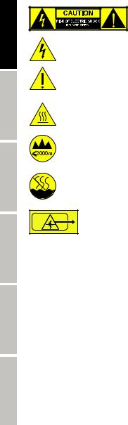
The warning triangle with lightning symbol indicates dangerous uninsulated voltage inside the unit, which may cause an electrical shock.
The warning triangle with exclamation mark indicates important operating and maintenance instructions.
The housing surface of the spotlight can heat up to temperatures as high as 70 °C in regular use. Ensure that it is not possible to come into contact with the housing unintentionally. Always allow sufficient time for the lamp to cool down before dismantling, carrying out maintenance work or charging etc.
Warning! This device is designed for use below 2000 metres in altitude.
Warning! This product is not intended for use in tropical climates.
Warning! The warning sign with the laser symbol indicates the laser emission aperture on the device.
DO NOT look directly into the laser beam. Risk of injury and blinding!
Do not expose yourself to the laser beam!
CAUTION! IMPORTANT INFORMATION ABOUT LIGHTING PRODUCTS!
1.The product has been developed for professional use in the field of event technology and is not suitable as household lighting.
2.Do not stare, even temporarily, directly into the light beam.
3.Do not look at the beam directly with optical instruments such as magnifiers.
4.Stroboscope effects may cause epileptic seizures in sensitive people! People with epilepsy should definitely avoid places where strobes are used.
CAUTION! IMPORTANT INFORMATION ABOUT LASER PRODUCTS!
1.The product has been developed for professional use in the field of event technology and is not suitable as household lighting.
2.This device includes a laser, the laser class is marked on the case and in the technical data and is in
accordance with the classification in compliance with EN 60825-1.
3.Under no circumstances should you look into the exiting laser beam. Risk of injury and blindness!
4.Avoid exposure to the laser beam. The laser beam can cause burns.
5.In this context, exercise extreme caution when using optical instruments (for example, magnifying glass, camera, binoculars, etc.)!
6.If installed incorrectly, or operated improperly, laser radiation may pose a fire and explosion hazard. Therefore, the device should only be operated by trained personnel.
7.In some countries, the installation or the operation of lasers is subject to approval. Please contact your local authority.
8.Appointing a laser safety officer for the installation is always advisable and even mandatory in some countries. Please observe your country-specific safety regulations and guidelines for the operation of a laser device.
9.The required safety distances between the device and the public at the site, or maximum permitted radiation values (MPR) must always be determined and their compliance with MPR limit values (country-specific) controlled by trained, qualified personnel.
10.Even if the laser diode is not illuminated, harmful radiation to the eye may be present. When unplugging the appliance, always disconnect all poles from the mains, when not in use.
11.Make sure that unauthorised people cannot operate the device, lock the lock switch and remove the associated key.
12.If the device has an interlock connector (from laser class 3B), it must be installed so that an emergency shutdown is possible at any time.
13.Before operating the device, the laser emission window must be checked for foreign objects (dust, dirt, nicotine deposits etc.), condensation, droplets of liquid and damage such as scratches and cracks. If the window is not in perfect condition, laser beams could be deflected in an uncontrolled manner. If this is the case, the show laser must not be used. Clean the laser emission window regularly and in the event of damage, have it replaced by an authorised service centre. The laser emission window must be in perfect condition to ensure safe operation of the show laser.
4
NOTE: This equipment has been tested and found to comply with the limits for a Class B digital device, pursuant to Part 15 of the FCC Rules. These limits are designed to provide reasonable protection against harmful interference in a residential installation. This equipment generates, uses and can radiate radio frequency energy and, if not installed and used in accordance with the instructions, may cause harmful interference to radio communications. However, there is no guarantee that interference will not occur in a particular installation. If this equipment does cause harmful interference to radio or television reception, which can be determined by turning the equipment off and on, the user is encouraged to try to correct the interference by one or more of the following measures:
-Reorient or relocate the receiving antenna.
-Increase the separation between the equipment and receiver.
-Connect the equipment into an outlet on a circuit different from that to which the receiver is connected.
-Consult the dealer or an experienced radio/TV technician for help.
INTRODUCTION
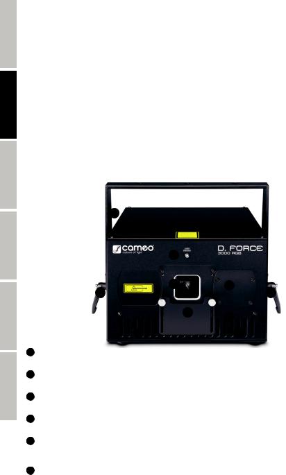
PROFESSIONAL SHOW LASER WITH R, G AND B DIODE LASERS
CLLDFORCE3000RGB
CONTROL FUNCTIONS:
ILDA
FEATURES:
Professional show laser. Dust-proof aluminium casing for minimum maintenance. 30 kpps high-speed galvo scanner @ 8° ILDA. Analogue modulation for up to 16 million colour shades. Precise beams with extremely low divergence for razor-sharp projections. Control via ILDA. Scan Fail Safety system with deactivation function (prevents emission of a dangerous spot beam). Neutrik powerCON mains input and output. Low-noise fan for controlled operating temperature. Operating voltage
100–240 V AC Power consumption 110 W.
CONNECTIONS, OPERATING AND DISPLAY ELEMENTS
|
1 |
|
|
|
4 |
|
|
|
3 |
|
6 |
|
2 |
|
2 |
|
|
5 |
7 |
|
|
|
|
|
8 |
|
8 |
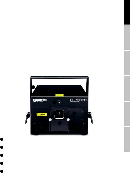
1 |
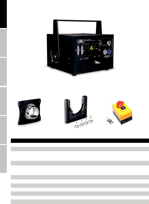
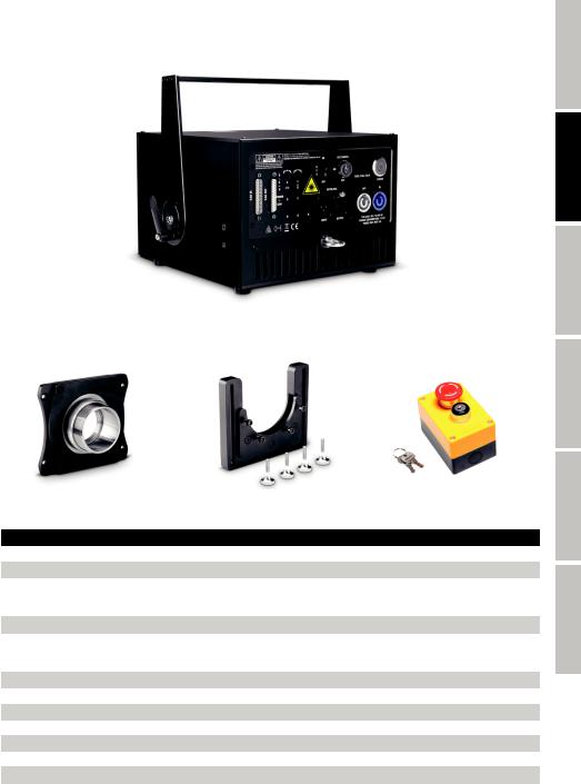
MOUNTING BRACKET |
|
|
Mounting bracket with attachment holes. |
|
|
|
2 |
CLAMP |
|
|
Clamp with angle-adjustable lever to clamp the mounting bracket. |
|
|
|
3 LASER EMISSION WINDOW
DO NOT look directly into the laser beam! Risk of injury and blinding!
4 LASER EMISSION
The LED indicator lights up as soon as a laser beam is emitted from the laser emission window.
5 COVER PANEL
Adjustable cover panel with knurled screws to limit the output range of the laser as required. Check the cover panel regularly to make sure it is in the correct position and take care to ensure that the position cannot change even if the device is exposed to heavy vibrations.
ENGLISH
FRANCAIS DEUTSCH
ESPAÑOL
POLSKI
ITALIANO
5
ENGLISH
FRANCAIS DEUTSCH
6 ADJUSTMENT COMPARTMENT
Loosen the four screws in the metal lid of the adjustment compartment using the 2 mm hex tool provided and remove the lid. Use the hex tool attached inside the adjustment compartment (1.5 mm) to adjust the laser beams R, G and B. For details of how to adjust the laser beams, see under LASER BEAM ADJUSTMENT in these instructions.
7 VENTILATION SLIT
Take care to ensure that the ventilation slits at the front and back are not covered and that air can circulate freely. Check the four internal fans regularly to ensure they are working correctly (visual check from the back) and have the device serviced by an authorised service centre at regular intervals.
8 RUBBER FEET
On the bottom of the device are four rubber feet for non-slip set-up on a suitable surface.
18
15 |
13 |
10 |
11 |
20
16 |
17 |
14 |
12 9
19
ESPAÑOL
POLSKI
ITALIANO
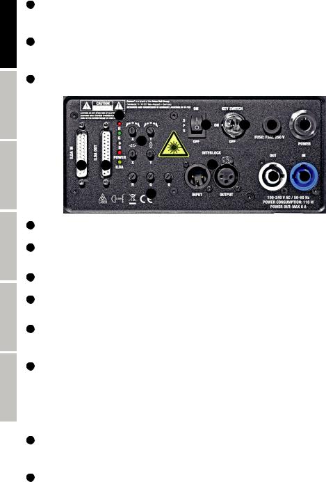
9 POWER IN
Neutrik powerCON mains input socket Operating voltage 100–240 V AC/50–60 Hz. Use the power cable provided.
10 FUSE HOLDER
Fuse holder for a 5 x 20 mm fine-wire fuse. Replace the fuse only with a fuse of the same type and of the same value according to the stamp on the device! In the event of repeated fuse failure, please contact an authorised service centre.
11 POWER
On/off switch for power supply to the device.
12 POWER OUT
Neutrik powerCON mains output socket for power supply to other CAMEO LIGHT products. Ensure that the total current consumption of all connected devices does not exceed the value specified on the device in amperes (A).
13 KEY SWITCH ON/OFF
Lock switch for switching the integrated laser on and off. The laser is deactivated in the OFF position and activated in the ON position. Two keys are included. In order to ensure the device cannot be operated by unauthorised persons, lock the switch and remove the key!
14 INTERLOCK
The interlock connection allows an emergency stop system to be set up so as to be able to switch off any connected effect lasers directly by remote control in the event of a hazard. Cameo D. FORCE lasers can only be operated if the interlock circuit is closed: when the emergency off switch is activated, a contact is opened, breaking the circuit.
INPUT: Male 3-pin XLR socket to connect the optionally available CAMEO emergency off switch with an XLR socket; use a commonly available microphone or DMX cable for this purpose. If the emergency off switch is not used, the bridging plug supplied has to be plugged into the interlock socket in order to be able to activate the laser. The bridging plug is for service purposes only and may not be used at events with an audience!
OUTPUT: Female 3-pin XLR socket to connect compatible laser products to the interlock emergency off system.
15 SFS ON/OFF
The Scan Fail Safety system prevents emission of a dangerous spot beam and should therefore be switched on at all times. Only deactivate the Scan Fail Safety system in exceptional cases (e.g. when adjusting the laser) and only if absolute care has been taken to ensure that persons, animals and combustible materials will not be hit by laser beams (also take care of mirrors and other reflecting materials)!
16 ILDA IN
ILDA input with 25-pin D-sub connector for computer control. ILDA software for show programming is not included.
6
17 ILDA OUT
25-pin D-sub connector to send the ILDA control signal.
18 DISPLAY LEDs
The display LEDs R, G and B light up as soon as the relevant laser beams leave the laser emission window. The POWER LED lights up as soon as the device is correctly connected to the mains and switched on.
The ILDA LED lights up as soon as an ILDA interface is connected at ILDA IN.
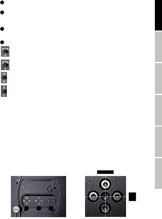
19 BRIGHTNESS REGULATOR R/G/B
Use the brightness regulator to set the brightness of lasers R, G and B as required (far left = laser dimmed to zero, far right = laser at maximum brightness).
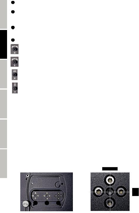
20 SET LASER PROJECTION
Horizontal rotation of projection, continuously variable from 0° to 180°.
Vertical rotation of projection, continuously variable from 0° to 180°.
Shift projection on the horizontal plane.
Shift projection on the vertical plane.
ENGLISH
FRANCAIS DEUTSCH
IMPORTANT
The lasers are ready to use approximately 10 seconds after switching on the device. When the lasers are activated using the lock switch and the emergency off switch, it likewise takes approximately 10 seconds before they are ready to use.
LASER BEAM ADJUSTMENT
Environmental factors such as bumps during transport, vibrations and temperature fluctuations etc. can lead to unintentional alterations to the alignment of the laser beams. They then have to be readjusted so as to ensure a consistent colour mixture and correct positioning of the laser projections. After removing the metal lid of the adjustment compartment using a 2 mm hex tool, use the hex tool attached inside the adjustment compartment (1.5 mm) to adjust the laser beams R, G and B.
Slightly loosen the adjustment screws (not the central attachment screw) required to adjust the relevant plane (vertical/horizontal). Use the horizontally arranged adjustment screws to correct the projection position of the laser on the vertical plane and the vertically arranged adjustment screws for positioning on the horizontal plane. One of the two adjustment screws always has to be loosened before the other adjustment screw can be tightened. The order in which this is carried out depends on the desired change in direction.
Start by adjusting the blue laser (B), generate a spot beam, move the regulators for shifting the projection on the horizontal and vertical plane (see Point 20) into the central position (snap-in point). Then adjust the laser beam so that it falls on the centre of the deflection mirror of the lower galvo scanner. Now select a circle or cross as a projection image and a distance from the projection surface of at least two metres (the greater the distance, the greater the degree of precision) and bring green (G) and red (R) successively into line with blue so that the projections of the laser beams are perfectly aligned to create a uniform colour mixture. Ensure that all adjustment and attachment screws are tightened after adjustment is complete, then carefully close the adjustment compartment again.
left – right
up
–
down
R G B
ESPAÑOL
POLSKI
ITALIANO
7
ENGLISH
FRANCAIS DEUTSCH
ESPAÑOL
POLSKI
ITALIANO
INSTALLATION AND MOUNTING
Thanks to its rubber feet, the device can be placed in a suitable position on a level surface. Mounting to a traverse is possible using the adjustable mounting bracket and a suitable traverse clamp (not supplied). Ensure a secure connection and attach the device to the safety eyelet (A) using a suitable safety cable.
Important: Overhead installation may only be carried out by qualified personnel.
A
OPTIONAL ACCESSORIES
CLLDFORCEAPDSL |
CLLDFORCEAPSSL |
CLLEKSXLR |
Adapter for Pangolin DiscoScan™ 2.0 lens |
Adapter for Pangolin Safety Scan lenses |
Emergency off switch with 3-pin XLR socket |
(similar to image)
TECHNICAL DATA
Article number: |
CLLDFORCE3000RGB |
Product type: |
Effects spotlight |
Type: |
Laser spotlight |
Colour spectrum: |
Red 638 nm |
|
Green 520 nm |
|
Blue 445 nm |
No. of diodes: |
1 x red, 1 x green, 1 x blue |
Diode types: |
Red 700 mW (laser diode) |
|
Green 800 mW (laser diode) |
|
Blue 1900 mW (laser diode) |
Stepper motors X/Y: |
30 kpps @ 8° ILDA |
Dispersion: |
50° |
Laser class: |
4 |
Beam data: |
≤ 4 x 2 mm/≤ 1 mrad |
Laser shutdown (safety function): |
Lock switch, interlock connector 3-pin XLR IN & OUT |
ILDA input: |
25-pin D-SUB connection, male |
ILDA output: |
25-pin D-SUB connection, female |
8
Operating controls: |
R, G, B, 4 regulators for laser projection, SFS ON/OFF, lock switch, on/off switch |
Display elements: |
6 indicator LEDs, illuminated on/off switch |
Power supply connection: |
Neutrik powerCON input and output. |
Maximum power out load rating: |
6 A |
Operating voltage: |
100–240 V AC, 50–60 Hz |
Power consumption: |
110 W |
Fuse: |
F3AL/250 V |
Ambient temperature (for operation): |
10°C–40°C |
Relative air humidity: |
10%–70%, non-condensing |
Housing material: |
Metal |
Housing colour: |
Black |
Housing cooling: |
Fan |
Dimensions (B x H x D, not incl. bracket): |
238 x 175 x 246 mm. |
Weight: |
7.9 kg |
Additional features: |
Power cable, adjustable mounting bracket, safety eyelet, bridging plug, two keys for lock |
|
switch included. 1.5 mm and 2 mm hex tool included Emergency off switch optional. Adapter |
|
for Pangolin DiscoScan™ 2.0 lens and adapter for Pangolin Safety Scan lenses optional |
MANUFACTURER´S DECLARATIONS
MANUFACTURER‘S WARRANTY & LIMITATIONS OF LIABILITY
You can find our current warranty conditions and limitations of liability at: https://cdn-shop.adamhall.com/media/pdf/Manufacturers-Decla- rations-CAMEO_DE_EN_ES_FR.pdf. To request warranty service for a product, please contact Adam Hall GmbH, Daimler Straße 9,
61267 Neu Anspach / Email: Info@adamhall.com / +49 (0)6081 / 9419-0.
CORRECT DISPOSAL OF THIS PRODUCT
(valid in the European Union and other European countries with a differentiated waste collection system)
 This symbol on the product, or on its documents indicates that the device may not be treated as household waste. This is to avoid environmental damage or personal injury due to uncontrolled waste disposal. Please dispose of this product separately from other waste and have it recycled to promote sustainable economic activity. Household users should contact either the retailer where they purchased this product, or their local government office, for details on where and how they can recycle this item in an environmentally friendly manner. Business users should contact their supplier and check the terms and conditions of the purchase contract. This product should not be mixed with other commercial waste for disposal.
FCC STATEMENT
This device complies with Part 15 of the FCC Rules. Operation is subject to the following two conditions:
(1)This device may not cause harmful interference, and
(2)This device must accept any interference received, including interference that may cause undesired operation
CE Compliance
Adam Hall GmbH states that this product meets the following guidelines (where applicable):
R&TTE (1999/5/EC) or RED (2014/53/EU) from June 2017
Low voltage directive (2014/35/EU)
EMV directive (2014/30/EU)
RoHS (2011/65/EU)
The complete declaration of conformity can be found at www.adamhall.com.
Furthermore, you may also direct your enquiry to info@adamhall.com.
ENGLISH
FRANCAIS DEUTSCH
ESPAÑOL
POLSKI
ITALIANO
9

ENGLISH
FRANCAIS DEUTSCH
ESPAÑOL
POLSKI
ITALIANO
DEUTSCH
SIE HABEN DIE RICHTIGE WAHL GETROFFEN!
Dieses Gerät wurde unter hohen Qualitätsanforderungen entwickelt und gefertigt, um viele Jahre einen reibungslosen Betrieb zu gewährleisten. Bitte lesen Sie diese Bedienungsanleitung sorgfältig, damit Sie Ihr neues Produkt von Cameo Light schnell und optimal einsetzen können. Weitere Informationen über Cameo Light erhalten Sie auf unserer Website WWW.CAMEOLIGHT.COM.
SICHERHEITSHINWEISE
1.Lesen Sie diese Anleitung bitte sorgfältig durch.
2.Bewahren Sie alle Informationen und Anleitungen an einem sicheren Ort auf.
3.Befolgen Sie die Anweisungen.
4.Beachten Sie alle Warnhinweise. Entfernen Sie keine Sicherheitshinweise oder andere Informationen vom Gerät.
5.Verwenden Sie das Gerät nur in der vorgesehenen Art und Weise.
6.Verwenden Sie ausschließlich stabile und passende Stative bzw. Befestigungen (bei Festinstallationen). Stellen Sie sicher, dass Wandhalterungen ordnungsgemäß installiert und gesichert sind. Stellen Sie sicher, dass das Gerät sicher installiert ist und nicht herunterfallen kann.
7.Beachten Sie bei der Installation die für Ihr Land geltenden Sicherheitsvorschriften.
8.Installieren und betreiben Sie das Gerät nicht in der Nähe von Heizkörpern, Wärmespeichern, Öfen oder sonstigen Wärmequellen. Sorgen Sie dafür, dass das Gerät immer so installiert ist, dass es ausreichend gekühlt wird und nicht überhitzen kann.
9.Platzieren Sie keine Zündquellen wie z.B. brennende Kerzen auf dem Gerät.
10.Lüftungsschlitze dürfen nicht blockiert werden.
11.Halten Sie einen Mindestabstand von 20 cm seitlich und oberhalb des Geräts ein.
12.Betreiben Sie das Gerät nicht in unmittelbarer Nähe von Wasser. Bringen Sie das Gerät nicht mit brennbaren Materialien, Flüssigkeiten oder Gasen in Berührung. Direkte Sonneneinstrahlung vermeiden!
13.Sorgen Sie dafür, dass kein Tropfoder Spritzwasser in das Gerät eindringen kann. Stellen Sie keine mit Flüssigkeit gefüllten Behältnisse wie Vasen oder Trinkgefäße auf das Gerät.
14.Sorgen Sie dafür, dass keine Gegenstände in das Gerät fallen können.
15.Betreiben Sie das Gerät nur mit dem vom Hersteller empfohlenen und vorgesehenen Zubehör.
16.Öffnen Sie das Gerät nicht und verändern Sie es nicht.
17.Überprüfen Sie nach dem Anschluss des Geräts alle Kabelwege, um Schäden oder Unfälle, z. B. durch Stolperfallen zu vermeiden.
18.Achten Sie beim Transport darauf, dass das Gerät nicht herunterfallen und dabei möglicherweise Sachund Personenschäden verursachen kann.
19.Wenn Ihr Gerät nicht mehr ordnungsgemäß funktioniert, Flüssigkeiten oder Gegenstände in das Geräteinnere gelangt sind, oder das Gerät anderweitig beschädigt wurde, schalten Sie es sofort aus und trennen es von der Netzsteckdose (sofern es sich um ein aktives Gerät handelt). Dieses Gerät darf nur von autorisiertem Fachpersonal repariert werden.
20.Verwenden Sie zur Reinigung des Geräts ein trockenes Tuch.
21.Beachten Sie alle in Ihrem Land geltenden Entsorgungsgesetze. Trennen Sie bei der Entsorgung der Verpackung bitte Kunststoff und Papier bzw. Kartonagen voneinander.
22.Kunststoffbeutel müssen außer Reichweite von Kindern aufbewahrt werden.
23.Sämtliche vom Benutzer vorgenommenen Änderungen und Modifikationen, denen die für die Einhaltung der Richtlinien verantwortliche Partei nicht ausdrücklich zugestimmt hat, können zum Entzug der Betriebserlaubnis für das Gerät führen.
BEI GERÄTEN MIT NETZANSCHLUSS:
24.ACHTUNG: Wenn das Netzkabel des Geräts mit einem Schutzkontakt ausgestattet ist, muss es an einer Steckdose mit Schutzleiter angeschlossen werden. Deaktivieren Sie niemals den Schutzleiter eines Netzkabels.
25.Schalten Sie das Gerät nicht sofort ein, wenn es starken Temperaturschwankungen ausgesetzt war (beispielsweise nach dem Transport). Feuchtigkeit und Kondensat könnten das Gerät beschädigen. Schalten Sie das Gerät erst ein, wenn es Zimmertemperatur erreicht hat.
26.Bevor Sie das Gerät an die Steckdose anschließen, prüfen Sie zuerst, ob die Spannung und die Frequenz des Stromnetzes mit den auf dem Gerät angegebenen Werten übereinstimmen. Verfügt das Gerät über einen Spannungswahlschalter, schließen Sie das Gerät nur an die Steckdose an, wenn die Gerätewerte mit den Werten des Stromnetzes übereinstimmen. Wenn das mitgelieferte Netzkabel bzw. der mitgelieferte Netzadapter nicht in Ihre Netzsteckdose passt, wenden Sie sich an Ihren Elektriker.
27.Treten Sie nicht auf das Netzkabel. Sorgen Sie dafür, dass spannungsführende Kabel speziell an der Netzbuchse bzw. am Netzadapter und der Gerätebuchse nicht geknickt werden.
28.Achten Sie bei der Verkabelung des Geräts immer darauf, dass das Netzkabel bzw. der Netzadapter stets frei zugänglich ist. Trennen Sie das Gerät stets von der Stromzuführung, wenn das Gerät nicht benutzt wird, oder Sie das Gerät reinigen möchten. Ziehen Sie Netzkabel und Netzadapter immer am Stecker bzw. am Adapter und nicht am Kabel aus der Steckdose. Berühren Sie Netzkabel und Netzadapter niemals mit nassen Händen.
29.Schalten Sie das Gerät möglichst nicht schnell hintereinander ein und aus, da sonst die Lebensdauer des Geräts beeinträchtigt werden könnte.
30.WICHTIGER HINWEIS: Ersetzen Sie Sicherungen ausschließlich durch Sicherungen des gleichen Typs und Wertes. Sollte eine Sicherung wiederholt auslösen, wenden Sie sich bitte an ein autorisiertes Servicezentrum.
31.Um das Gerät vollständig vom Stromnetz zu trennen, entfernen Sie das Netzkabel bzw. den Netzadapter aus der Steckdose.
32.Wenn Ihr Gerät mit einem Volex-Netzanschluss bestückt ist, muss der passende Volex-Gerätestecker entsperrt werden, bevor er entfernt werden kann. Das bedeutet aber auch, dass das Gerät durch ein Ziehen am Netzkabel verrutschen und herunterfallen kann, wodurch Personen verletzt werden und/oder andere Schäden auftreten können. Verlegen Sie Ihre Kabel daher immer sorgfältig.
33.Entfernen Sie Netzkabel und Netzadapter aus der Steckdose bei Gefahr eines Blitzschlags oder wenn Sie das Gerät länger nicht verwenden.
34.Das Gerät darf nur im spannungsfreien Zustand (Trennung des Netzsteckers vom Stromnetz) installiert werden.
35.Staub und andere Ablagerungen im Inneren des Geräts können es beschädigen. Das Gerät sollte je nach Umgebungsbedingungen (Staub, Nikotin, Nebel etc.) regelmäßig von qualifiziertem Fachpersonal gewartet bzw. gesäubert werden (keine Garantieleistung),
10um Überhitzung und Fehlfunktionen zu vermeiden.
36.Der Abstand zu brennbaren Materialien muss mindestens 0,5 m betragen.
37.Netzleitungen zur Spannungsversorgung mehrerer Geräte müssen mindestens 1,5 mm² Aderquerschnitt aufweisen. In der EU müssen die Leitungen H05VV-F, oder gleichartig, entsprechen. Geeignete Leitungen werden von Adam Hall angeboten. Mit diesen Leitungen können Sie mehrere Geräte über den Power out Anschluss mit dem Power IN Anschluss eines weiteren Gerätes verbinden. Beachten Sie, dass die gesamte Stromaufnahme aller angeschlossenen Geräte den vorgegebenen Wert nicht überschreitet (Aufdruck auf dem Gerät). Achten Sie darauf, Netzleitungen so kurz wie möglich zu halten.
ACHTUNG
Entfernen Sie niemals die Abdeckung, da sonst das Risiko eines elektrischen Schlages besteht. Im

 Inneren des Geräts befinden sich keine Teile, die vom Bediener repariert oder gewartet werden können.
  Lassen Sie Wartung und Reparaturen ausschließlich von qualifiziertem Servicepersonal durchführen.
Das gleichseitige Dreieck mit Blitzsymbol warnt vor nichtisolierten, gefährlichen Spannungen im Geräteinneren, die einen elektrischen Schlag verursachen können.
Das gleichseitige Dreieck mit Ausrufungszeichen kennzeichnet wichtige Bedienungsund Wartungshinweise.
Warnung! Dieses Symbol kennzeichnet heiße Oberflächen. Während des Betriebs können bestimmte Teile des Gehäuses heiß werden. Berühren oder transportieren Sie das Gerät nach einem Einsatz erst nach einer Abkühlzeit von mindestens 10 Minuten.
Warnung! Dieses Gerät ist für eine Nutzung bis zu einer Höhe von maximal 2000 Metern über dem Meeresspiegel bestimmt.
Warnung! Dieses Gerät ist nicht für den Einsatz in tropischen Klimazonen bestimmt.
Warnung! Das Warnzeichen mit dem Lasersymbol kennzeichnet die Laseraustrittsöffnung am Gerät.
Unter keinen Umständen in den austretenden Laserstrahl blicken. Verletzungsund Erblindungsgefahr!
Nicht dem Laserstrahl aussetzen!
VORSICHT! WICHTIGE HINWEISE IN BEZUG AUF LICHT-PRODUKTE!
1.Das Produkt ist für den professionellen Einsatz im Bereich der Veranstaltungstechnik entwickelt worden und ist nicht für die Raumbeleuchtung in Haushalten geeignet.
2.Blicken Sie niemals, auch nicht kurzzeitig, direkt in den Lichtstrahl.
3.Blicken Sie niemals mit optischen Geräten wie Vergrößerungsgläsern in den Lichtstrahl.
4.Stroboskopeffekte können unter Umständen bei empfindlichen Menschen epileptische Anfälle auslösen! Epilepsiekranke Menschen sollten daher unbedingt Orte meiden, an denen Stroboskopeffekte eingesetzt werden.
VORSICHT! WICHTIGE HINWEISE IN BEZUG AUF LASER-PRODUKTE!
1.Das Produkt ist für den professionellen Einsatz im Bereich der Veranstaltungstechnik entwickelt worden und ist nicht für die Raumbeleuchtung in Haushalten geeignet.
2.Dieses Gerät beinhaltet einen Laser der auf dem Gehäuse und in den technischen Daten gekennzeichneten Laserklasse entsprechend der Klassifizierung nach EN 60825-1.
3.Unter keinen Umständen in den austretenden Laserstrahl blicken. Verletzungsund Erblindungsgefahr!
4.Nicht dem Laserstrahl aussetzen. Der Laserstrahl kann Verbrennungen hervorrufen.
5.In diesem Zusammenhang auch erhöhte Vorsicht bei Verwendung optischer Instrumente (z.B. Vergrößerungsglas, Fotoapparat, Fernglas etc.)!
6.Bei falscher Installation, bzw. Anwendung kann Laserstrahlung eine Feuerund Explosionsgefahr darstellen. Daher sollte die Inbetriebnahme nur von geschultem Fachpersonal erfolgen.
7.In einigen Ländern ist die Installation bzw. das Betreiben von Lasern genehmigungspflichtig. Bitte wenden Sie sich an Ihre zuständige Behörde.
8.Einen Laserschutzbeauftragten für die Inbetriebnahme zu bestellen ist immer ratsam und in einigen Ländern sogar vorgeschrieben. Bitte beachten Sie Ihre länderspezifischen Sicherheitsbestimmungen und Richtlinien für den Betrieb des Lasergeräts.
9.Die am Betriebsort geforderten Sicherheitsabstände zwischen Gerät und Publikum, bzw. maximal zulässige Bestrahlungswerte (MZB) müssen immer von geschultem Fachpersonal ermittelt und deren Einhaltung kontrolliert werden (MZB Grenzwerte länderspezifisch).
10.Auch wenn die Laserdiode augenscheinlich nicht leuchtet, kann für das Auge schädliche Strahlung austreten. Trennen Sie daher das Gerät stets allpolig vom Stromnetz, wenn es nicht verwendet werden soll.
11.Stellen sie sicher, dass unbefugte Personen das Gerät nicht in Betrieb nehmen können, verriegeln Sie hierzu den Schloss-Schalter und entfernen den dazugehörigen Schlüssel.
12.Wenn das Gerät über einen Interlock Anschluss verfügt (ab Laser-Klasse 3B), muss es so installiert werden, dass eine Not-Abschaltung jederzeit möglich ist.
ENGLISH
FRANCAIS DEUTSCH
ESPAÑOL
POLSKI
ITALIANO
11
ENGLISH
13. Das Laseraustrittsfenster muss vor jeder Inbetriebnahme des Geräts auf Verunreinigung (Staub, Schmutz, Nikotinablagerungen usw.), Kondenswasserbildung, Tropfen von Flüssigkeiten und Beschädigungen wie Kratzer und Risse überprüft werden. Wenn sich das Fenster nicht in einem einwandfreiem Zustand befindet, können Laserstrahlen unkontrolliert abgelenkt werden. In diesem Fall darf der Show-Laser nicht in Betrieb genommen werden. Reinigen Sie das Laseraustrittsfenster regelmäßig und lassen das Fenster im Fall einer Beschädigung von einem autorisierten Servicezentrum austauschen. Nur wenn sich das Laseraustrittsfenster in einem einwandfreiem Zustand befindet, ist ein sicherer Betrieb des Show-Lasers möglich.
EINFÜHRUNG
FRANCAIS DEUTSCH
PROFESSIONELLER SHOW-LASER MIT R, G UND B DIODEN-LASERN
CLLDFORCE3000RGB
STEUERUNGSFUNKTIONEN:
ILDA
EIGENSCHAFTEN:
Professioneller Show-Laser. Staubdichtes Aluminiumgehäuse für minimalen Wartungsaufwand. 30 Kpps HochgeschwindigkeitsGalvoscanner @ 8° ILDA. Analoge Modulation für bis zu 16 Millionen Farbschattierungen. Präzise Strahlen mit extrem geringer Divergenz für messerscharfe Projektionen. Steuerung über ILDA. Abschaltbares Scan Fail Safety-System (verhindert das Austreten eines gefährlichen Punktstrahls). Neutrik powerCON Netzeinund Ausgang. Geräuscharmer Lüfter für kontrollierte Betriebstemperatur. Betriebsspannung 100V - 240V AC. Leistungsaufnahme 110W.
ANSCHLÜSSE, BEDIENUND ANZEIGEELEMENTE
1
ESPAÑOL |
4 |
|
|
|
|
|
|
|
3 |
|
6 |
POLSKI |
2 |
|
2 |
|
5 |
7 |
|
|
|
|
|
|
8 |
|
8 |
1 MONTAGEBÜGEL
Montagebügel mit Befestigungslöchern.
ITALIANO
2 KLEMMHEBEL
Klemmhebel mit winkelverstellbarem Hebel zum Festklemmen des Montagebügels.
3 LASERAUSTRITTSFENSTER
Unter keinen Umständen in den austretenden Laserstrahl blicken! Verletzungsund Erblindungsgefahr!
4 LASER EMISSION
Die Anzeige-LED leuchtet, sobald ein Laserstrahl aus dem Laseraustrittsfenster austritt.
5 ABDECKPLATTE
Verstellbare Abdeckplatte mit Rändelschrauben um den Ausgabebereich des Lasers bei Bedarf zu begrenzen. Kontrollieren Sie regelmäßig die Abdeckplatte auf korrekte Position und achten darauf, dass sich ihre Position selbst bei starken Vibrationen nicht verändern kann.
6 JUSTIERFACH
Lösen Sie die vier Schrauben im Metalldeckel des Justierfachs mit Hilfe des mitgelieferten 2mm Sechskantwerkzeugs und entnehmen den Deckel. Um die Laserstrahlen R, G und B zu justieren, nutzen Sie das im Justierfach angebrachte Sechskantwerkzeug (1,5 mm). Eine
12Anleitung für die Justierung der Laserstrahlen finden Sie in dieser Anleitung unter LASERSTRAHL-JUSTIERUNG.

7 LÜFTUNGSSCHLITZE
Achten Sie darauf, dass die Lüftungsschlitze auf Vorderund Rückseite nicht abgedeckt werden und Luft ungehindert zirkulieren kann. Überprüfen Sie die 4 internen Lüfter regelmäßig auf korrekte Funktion (Sichtprüfung von der Rückseite) und lassen das Gerät von einem autorisierten Servicezentrum in regelmäßigen Abständen warten.
8 GUMMIFÜSSE
Auf der Unterseite des Geräts befinden sich vier Gummifüße für die rutschfreie Aufstellung auf einer geeigneten Fläche.
|
18 |
|
|
|
|
15 |
13 |
10 |
11 |
|
20 |
|
|
|
16 |
17 |
14 |
|
|
|
|
|
12 |
9 |
|
19 |
|
|
|
9 POWER IN
Neutrik powerCON Netzeingangsbuchse. Betriebsspannung 100 - 240V AC / 50 - 60Hz. Anschluss mit Hilfe des mitgelieferten Netzkabels.
10 SICHERUNGSHALTER
Sicherungshalter für eine 5 x 20mm Feinsicherung. Ersetzen Sie die Sicherung ausschließlich durch eine Sicherung des gleichen Typs und mit gleichen Werten entsprechend des Aufdrucks auf dem Gerät! Sollte die Sicherung wiederholt auslösen, wenden Sie sich bitte an ein autorisiertes Servicezentrum.
11 POWER
Ein- / Ausschalter für die Spannungszufuhr des Geräts.
12 POWER OUT
Neutrik powerCON Netzausgangsbuchse für die Netzversorgung weiterer CAMEO LIGHT Produkte. Achten Sie darauf, dass die gesamte Stromaufnahme aller angeschlossenen Geräte den auf dem Gerät in Ampere (A) angegebenen Wert nicht überschreitet.
13 KEY SWITCH ON / OFF
Schloss-Schalter zum Einund Ausschalten der integrierten Laser. In Position OFF sind die Laser deaktiviert, in Position ON aktiviert. Zwei Schlüssel sind im Lieferumfang enthalten. Stellen Sie sicher, dass unbefugte Personen das Gerät nicht in Betrieb nehmen können, verriegeln Sie hierzu den Schloss-Schalter und entfernen den dazugehörigen Schlüssel!
14 INTERLOCK
Der Interlock-Anschluss dient der Einrichtung eines Not-Aus-Systems, um im Falle einer Gefahrensituation angeschlossene Effekt-Laser unmittelbar ferngesteuert abschalten zu können. Cameo D. FORCE Laser können nur bei geschlossenem Interlock-Schaltkreis in Betrieb genommen werden, beim Betätigen des Not-Aus-Schalters wird ein Kontakt geöffnet und der Schaltkreis somit unterbrochen.
INPUT: Männliche 3-Pol XLR-Buchse zum Anschließen des optional erhältlichen CAMEO Not-Aus-Schalters mit XLR-Buchse, verwenden Sie hierzu ein handelsübliches Mikrofonoder DMX-Kabel. Wird der Not-Aus-Schalter nicht verwendet, muss der mitgelieferte Brückenstecker an der Interlock-Buchse angeschlossen sein, um den Laser aktivieren zu können. Der Brückenstecker dient ausschließlich
Servicezwecken und darf bei Veranstaltungen mit Publikum nicht verwendet werden!
OUTPUT: Weibliche 3-Pol XLR-Buchse zum Anschließen kompatibler Laser-Produkte an das Interlock Not-Aus-System.
15 SFS ON / OFF
Das Scan Fail Safety-System verhindert das Austreten eines gefährlichen Punktstrahls und sollte daher permanent eingeschaltet sein. Schalten Sie das Scan Fail Safety-System nur in Ausnahmefällen aus (z.B. Laser Justierung) und auch nur dann, wenn absolut sichergestellt ist, dass Personen, Tiere und brennbare Materialien nicht von Laserstrahlen getroffen werden können (Spiegel und andere reflektierende Materialien beachten)!
16 ILDA IN
ILDA-Eingang mit 25-poligem D-Sub-Verbinder für die Computer-Steuerung. Eine ILDA-Software für die Show-Programmierung ist nicht im Lieferumfang enthalten.
ENGLISH
FRANCAIS DEUTSCH
ESPAÑOL
POLSKI
ITALIANO
13
ENGLISH
FRANCAIS DEUTSCH
17 ILDA OUT
25-poliger D-Sub-Verbinder zum Weiterleiten des ILDA-Steuersignals.
18 ANZEIGE LEDS
Die Anzeige-LEDs R, G und B leuchten, sobald die entsprechenden Laserstrahlen das Laseraustrittsfenster verlassen. Die POWER-LED leuchtet, sobald das Gerät korrekt am Stromnetz angeschlossen und eingeschaltet ist.
Die ILDA-LED leuchtet, sobald ein ILDA-Interface am ILDA IN Anschluss angeschlossen ist.
19 HELLIGKEITSSTELLER R / G / B
Nutzen Sie die Helligkeitssteller, um die Helligkeit der Laser R, G und B nach Wunsch einzustellen (Linksanschlag = Laser auf null gedimmt, Rechtsanschlag = Laser mit maximaler Helligkeit).
20 EINSTELLEN DER LASER-PROJEKTION
Horizontale Drehung der Projektion, stufenlos von 0° bis 180°.
Vertikale Drehung der Projektion, stufenlos von 0° bis 180°.
Verschieben der Projektion auf der horizontalen Ebene.
ESPAÑOL
Verschieben der Projektion auf der vertikalen Ebene.
HINWEIS
Die Laser sind circa 10 Sekunden nach dem Einschalten des Geräts einsatzbereit. Nach dem Aktivieren der Laser mit Hilfe des Schloss-Schalters und des Not-Aus-Schalters dauert es ebenso circa 10 Sekunden, bis die Laser einsatzbereit sind.
LASERSTRAHL-JUSTIERUNG
POLSKI
ITALIANO
Durch äußere Einflüsse, wie Stöße beim Transport, Vibration und Temperaturschwankungen usw. ist es möglich, dass die Ausrichtung der Laserstrahlen ungewollt verändert wird und somit neu justiert werden muss, um eine einheitliche Farbmischung und Position der LaserProjektionen zu gewährleisten. Nachdem Sie den Metalldeckel des Justierfachs mit Hilfe eines 2 mm Sechskantwerkzeugs entfernt haben, nutzen Sie das im Justierfach angebrachte Sechskantwerkzeug (1,5 mm), um die Laserstrahlen R, G und B zu justieren.
Lösen Sie nur die Stellschrauben leicht (nicht die zentrale Befestigungsschraube), die für die Justierung auf der entsprechenden Ebene (vertikal / horizontal) benötigt werden. Korrigieren Sie mit Hilfe der waagerecht angeordneten Stellschrauben die Projektionsposition des Lasers auf vertikaler Ebene und die senkrecht angeordneten Stellschrauben auf horizontaler Ebene. Eine der beiden Stellschrauben
muss immer zuerst gelöst werden, bevor die andere Stellschraube angezogen werden kann. Die Reihenfolge hängt von der gewünschten Richtungskorrektur ab.
Beginnen Sie bei der Justierung mit dem blauen Laser (B), erzeugen einen Punktstrahl, bringen die Regler zum Verschieben der Projektion auf horizontaler und vertikaler Ebene (siehe Punkt 20) in Mittelstellung (Rastpunkt) und justieren den Laserstrahl so, dass er in der
Mitte des Umlenkspiegels des unteren Galvo-Scanners auftrifft. Wählen Sie nun als Projektionsmotiv einen Kreis oder ein Kreuz, eine Distanz zur Projektionsfläche von mindestens 2 Metern (je größer die Distanz, desto größer die Präzision) und gleichen Grün (G) und Rot (R) nacheinander mit Blau ab, in der Art, dass beim Justieren die Projektionen der Laserstrahlen perfekt übereinanderliegen und eine einheitliche Farbmischung entsteht. Stellen Sie sicher, dass nach der Justierung alle Stellund zentralen Befestigungsschrauben festgezogen sind und verschließen das Justierfach wieder sorgfältig.
hoch
-
runter
R G B
14
AUFSTELLUNG UND MONTAGE
Dank der Gummifüße auf der Unterseite kann das Gerät an einer geeigneten Stelle auf eine ebene Fläche gestellt werden. Die Montage an einer Traverse erfolgt mit Hilfe des verstellbaren Montagebügels und einer geeigneten Traversenklemme (nicht im Lieferumfang enthalten). Sorgen Sie für eine feste Verbindung und sichern Sie das Gerät mit einem geeigneten Sicherungsseil an der Sicherungsöse (A).
Wichtiger Hinweis: Überkopfmontage darf nur von dafür ausgebildetem Personal durchgeführt werden.
ENGLISH
DEUTSCH
A
OPTIONALES ZUBEHÖR
CLLDFORCEAPDSL |
CLLDFORCEAPSSL |
CLLEKSXLR |
Adapter für Pangolin DiscoScan™ 2.0 Linse |
Adapter für Pangolin Safety Scan Linsen |
Not-Aus-Schalter mit 3-Pol XLR-Buchse |
FRANCAIS
ESPAÑOL
TECHNISCHE DATEN
(Abbildung ähnlich)
POLSKI
Artikelnummer: |
CLLDFORCE3000RGB |
Produktart: |
Effekt-Strahler |
Typ: |
Laser-Strahler |
Farbspektrum: |
Rot 638 nm |
|
Grün 520 nm |
|
Blau 445 nm |
Dioden Anzahl: |
1x Rot, 1x Grün, 1x Blau |
Dioden Typ: |
Rot 700 mW (Laser Diode) |
|
Grün 800 mW (Laser Diode) |
|
Blau 1900 mW (Laser Diode) |
Schrittmotoren X / Y: |
30 kpps @ 8° ILDA |
Abstrahlwinkel: |
50° |
Laserklasse: |
4 |
Strahldaten: |
≤ 4 x 2 mm / ≤ 1 mrad |
Laser Abschaltung (Sicherheitsfunktion): |
Schloss-Schalter, Interlock-Anschluss 3-Pol XLR IN & OUT |
ILDA-Eingang: |
25-Pin D-SUB Anschluss männlich |
ILDA Ausgang: |
25-Pin D-SUB Anschluss weiblich |
Bedienelemente: |
R, G, B, 4 Regler für Laser-Projektion, SFS ON / OFF, Schloss-Schalter, Ein- / Aus-Schalter |
ITALIANO
15
 Loading...