


USER´S MANUAL
BEDIENUNGSANLEITUNG
MANUEL D´UTILISATION
MANUAL DE USUARIO
INSTRUKCJA OBSŁUGI
MANUALE D´USO
AURO SPOT Z 300
CLASZ300
CONTENTS / INHALTSVERZEICHNIS / CONTENU / CONTENIDO / TREŚĆ / CONTENUTO
ENGLISH |
|
ESPAÑOL |
|
|
PREVENTIVE MEASURES |
3-4 |
MEDIDAS DE SEGURIDAD |
45-46 |
|
INTRODUCTION |
5 |
INTRODUCCIÓN |
47 |
|
CONNECTIONS, CONTROLS, AND DISPLAY ELEMENTS |
5-6 |
CONEXIONES, ELEMENTOS DE MANEJO Y ELEMENTOS |
|
|
OPERATION |
6-12 |
DE VISUALIZACIÓN |
47-48 |
|
SETUP AND INSTALLATION |
13 |
MANEJO |
48-54 |
|
DMX TECHNOLOGY |
14 |
INSTALACIÓN Y MONTAJE |
55 |
|
TECHNICAL SPECIFICATIONS |
15 |
TECNOLOGÍA DMX |
56 |
|
MANUFACTURER'S DECLARATIONS |
16 |
DATOS TÉCNICOS |
57 |
|
DMX CONTROL |
87-92 |
DECLARACIONES DEL FABRICANTE |
58 |
|
DEUTSCH |
|
CONTROL DMX |
87-92 |
|
|
JĘZYK POLSKI |
|
||
SICHERHEITSHINWEISE |
17-18 |
|
||
EINFÜHRUNG |
19 |
ŚRODKI OSTROŻNOŚCI |
59-60 |
|
ANSCHLÜSSE, BEDIENUND ANZEIGEELEMENTE |
19-20 |
WPROWADZENIE |
61 |
|
BEDIENUNG |
20-26 |
PRZYŁĄCZA, ELEMENTY OBSŁUGI I WSKAŹNIKI |
61-62 |
|
AUFSTELLUNG UND MONTAGE |
27 |
OBSŁUGA |
62-68 |
|
DMX TECHNIK |
28 |
USTAWIANIE I MONTAŻ |
69 |
|
TECHNISCHE DATEN |
29 |
TECHNIKA DMX |
70 |
|
HERSTELLERERKLÄRUNGEN |
30 |
DANE TECHNICZNE |
71 |
|
DMX STEUERUNG |
87-92 |
OŚWIADCZENIA PRODUCENTA |
72 |
|
FRANÇAIS |
|
STEROWANIE DMX |
87-92 |
|
|
ITALIANO |
|
||
MESURES PRÉVENTIVES |
31-32 |
|
||
INTRODUCTION |
33 |
MISURE PRECAUZIONALI |
73-74 |
|
RACCORDEMENTS, ÉLÉMENTS DE COMMANDE ET |
|
|||
|
INTRODUZIONE |
75 |
||
D’AFFICHAGE |
33-34 |
|||
CONNESSIONI, ELEMENTI DI COMANDO E |
|
|||
UTILISATION |
34-40 |
|
||
DI VISUALIZZAZIONE |
75-76 |
|||
INSTALLATION ET MONTAGE |
41 |
|||
UTILIZZO |
76-82 |
|||
TECHNOLOGIE DMX |
42 |
|||
INSTALLAZIONE E MONTAGGIO |
83 |
|||
DONNÉES TECHNIQUES |
43 |
|||
TECNOLOGIA DMX |
84 |
|||
DÉCLARATIONS DU FABRICANT |
44 |
|||
DATI TECNICI |
85 |
|||
PILOTAGE DMX |
87-92 |
|||
DICHIARAZIONI DEL PRODUTTORE |
86 |
|||
|
|
|||
|
|
CONTROLLO DMX |
87-92 |

ENGLISH
YOU‘VE MADE THE RIGHT CHOICE!
We have designed this product to operate reliably over many years. Please read this User‘s Manual carefully, so that you can begin making optimum use of your Cameo Light product quickly. Learn more about Cameo Light on our website WWW.CAMEOLIGHT.COM.
PREVENTIVE MEASURES
1.Please read these instructions carefully.
2.Keep all information and instructions in a safe place.
3.Follow the instructions.
4.Observe all safety warnings. Never remove safety warnings or other information from the equipment.
5.Use the equipment only in the intended manner and for the intended purpose.
6.Use only sufficiently stable and compatible stands and/or mounts (for fixed installations). Make certain that wall mounts are properly installed and secured. Make certain that the equipment is installed securely and cannot fall down.
7.During installation, observ e the applicable safety regulations for your country.
8.Never install and operate the equipment near radiators, heat registers, ovens or other sources of heat. Make certain that the equipment is always installed so that is cooled sufficiently and cannot overheat.
9.Never place sources of ignition, e.g., burning candles, on the equipment.
10.Ventilation slits must not be blocked.
11.This appliance is designed exclusively for indoor use, do not use this equipment in the immediate vicinity of water (does not apply
to special outdoor equipment - in this case, observe the special instructions noted below). Do not expose this equipment to flammable materials, fluids or gases.
12.Make certain that dripping or splashed water cannot enter the equipment. Do not place containers filled with liquids, such as vases or drinking vessels, on the equipment.
13.Make certain that objects cannot fall into the device.
14.Use this equipment only with the accessories recommended and intended by the manufacturer.
15.Do not open or modify this equipment.
16.After connecting the equipment, check all cables in order to prevent damage or accidents, e.g., due to tripping hazards.
17.During transport, make certain that the equipment cannot fall down and possibly cause property damage and personal injuries.
18.If your equipment is no longer functioning properly, if fluids or objects have gotten inside the equipment or if it has been damaged in anot her way, switch it off immediately and unplug it from the mains outlet (if it is a powered device). This equipment may only be repaired by authorized, qualified personnel.
19.Clean the equipment using a dry cloth.
20.Comply with all applicable disposal laws in your country. During disposal of packaging, please separate plastic and paper/cardboard.
21.Plastic bags must be kept out of reach of children.
FOR EQUIPMENT THAT CONNECTS TO THE POWER MAINS:
22. CAUTION: If the power cord of the device is equipped with an earthing contact, then it must be connected to an outlet with a protective ground. Never deactivate the protective ground of a power cord.
23. If the equipment has been exposed to strong fluctuations in temperature (for example, after transport), do not switch it on immediately. Moisture and condensation could damage the equipment. Do not switch on the equipment until it has reached room temperature.
24. Before connecting the equipment to the power outlet, first verify that the mains voltage and frequency match the values specified on the equipment. If the equipment has a voltage selection switch, connect the equipment to the power outlet only if the equipment values and the mains power values match. If the included power cord or power adapter does not fit in your wall outlet, contact your electrician.
25. Do not step on the power cord. Make certain that the power cable does not become kinked, especially at the mains outlet and/or power adapter and the equipment connector.
26. When connecting the equipment, make certain that the power cord or power adapter is always freely accessible. Always disconnect the equipment from the power supply if the equipment is not in use or if you want to clean the equipment. Always unplug the power cord and power adapter from the power outlet at the plug or adapter and not by pulling on the cord. Never touch the power cord and power adapter with wet hands.
27. Whenever possible, avoid switching the equipment on and off in quick succession because otherwise this can shorten the useful life of the equipment.
28. IMPORTANT INFORMATION: Replace fuses only with fuses of the same type and rating. If a fuse blows repeatedly, please contact an authorised service centre.
29. To disconnect the equipment from the power mains completely, unplug the power cord or power adapter from the power outlet.
30. If your device is equipped with a Volex power connector, the mating Volex equipment connector must be unlocked before it can be removed. However, this also means that the equipment can slide and fall down if the power cable is pulled, which can lead to personal injuries and/or other damage. For this reason, always be careful when laying cables.
31. Unplug the power cord and power adapter from the power outlet if there is a risk of a lightning strike or before extended periods of disuse. 32. The device must only be installed in a voltage-free condition (disconnect the mains plug from the mains).
33. Dust and other debris inside the unit may cause damage. The unit should be regularly serviced or cleaned (no guarantee) depending on ambient conditions (dust etc., nicotine, fog) by qualified personnel to prevent overheating and malfunction.
34. Please keep a distance of at least 0.5 m to any combustible materials.
35. Power cables to power multiple devices must have a cross-section of at least 1.5 mm². Within the EU, the cables must correspond to H05VV-F, or similar. Suitable cables are offered by Adam Hall. With these cables, you can connect multiple devices via the power OUT connection to the power IN connection of an additional device. Make sure that the total current consumption of all connected devices does not
exceed the specified value on all connected devices (label on the device). Make sure to keep power cable connections as short as possible.
3
ENGLISH
FRANCAIS DEUTSCH
ESPAÑOL
POLSKI
ITALIANO
DMX
ENGLISH
FRANCAIS DEUTSCH
ESPAÑOL
POLSKI
ITALIANO
DMX
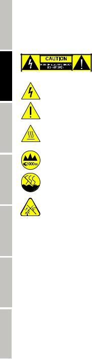
CAUTION:
To reduce the risk of electric shock, do not remove cover (or back). There are no user serviceable parts inside. Maintenance and repairs should be exclusively carried out by qualified service
personnel.
The warning triangle with lightning symbol indicates dangerous uninsulated voltage inside the unit, which may cause an electrical shock.
The warning triangle with exclamation mark indicates important operating and maintenance instructions.
Warning! This symbol indicates a hot surface. Certain parts of the housing can become hot during operation. After use, wait for a cool-down period of at least 10 minutes before handling or transporting the device.
Warning! This device is designed for use below 2000 metres in altitude.
Warning! This product is not intended for use in tropical climates.
Caution! Intense LED light source! Risk of eye damage. Do not look into the light source.
CAUTION! IMPORTANT INFORMATION ABOUT LIGHTING PRODUCTS!
1.The product has been developed for professional use in the field of event technology and is not suitable as household lighting.
2.Do not stare, even temporarily, directly into the light beam.
3.Do not look at the beam directly with optical instruments such as magnifiers.
4.Stroboscope effects may cause epileptic seizures in sensitive people! People with epilepsy should definitely avoid places where strobes are used.
4
INTRODUCTION
LED MOVING HEAD AURO SPOT ZOOM 300
CLASZ300
CONTROL FUNCTIONS:
17-channel and 20-channel DMX control Master/Slave mode
Stand-alone functions:
PROPERTIES:
LED moving head with 200 W LED. Color wheel and two gobo wheels. Zoom function. Focus. Frost filter. Two prisms. Two DMX modes. DMX512 control. Master/Slave mode. Stand-alone functions. Two omega mounting brackets included. Operating voltage: 100V–240 V AC / 50–60 Hz. Power consumption: 320 W.
The spotlight complies with the RDM standard (Remote Device Management). This device manager allows the user to request the status of and configure RDM end devices via an RDM-capable controller.
CONNECTIONS, CONTROLS, AND DISPLAY ELEMENTS
ENGLISH
DEUTSCH
1 |
4 |
5 |
|
3 |
|
|
6 |
7 |
FRANCAIS
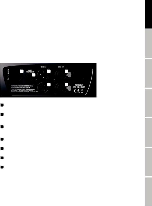
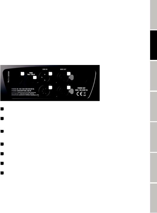
1 POWER IN
Neutrik powerCON mains input socket. Operating voltage: 100–240 V AC / 50–60 Hz. A suitable power cable is included in delivery.
2 POWER OUT
Neutrik powerCON mains output socket. Serves to provide power to additional CAMEO spotlights. Ensure that the total power consumption of all devices connected to the device does not exceed the given ampere (A) value.
3 FUSE HOLDER
IMPORTANT NOTE: Exclusively replace the fuse with a fuse of the same type and values. If a fuse trips repeatedly, please contact an authorized service center.
4 DMX IN
Male three-pin XLR connector to connect a DMX control device (e.g. DMX console).
5 DMX OUT
Female three-pin XLR connector to transmit the DMX control signal.
6 DMX IN
Male five-pin XLR connector to connect a DMX control device (e.g. DMX console).
7 DMX OUT
Female five-pin XLR connector to transmit the DMX control signal.
ESPAÑOL
POLSKI
ITALIANO
DMX
5
ENGLISH
FRANCAIS DEUTSCH
ESPAÑOL
POLSKI
ITALIANO
DMX
8 |
9 |
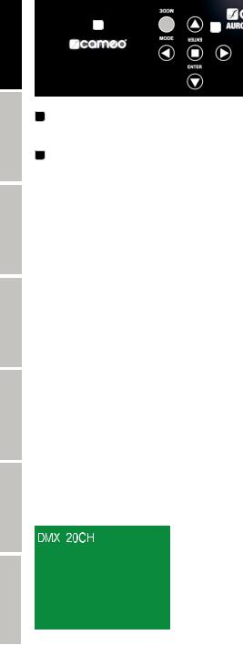
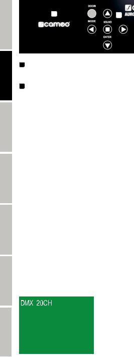
8 BACKLIT LC DISPLAY
Displays the currently activated operating mode, the options menu, and other system information. The display automatically switches to the main screen after approx. one minute of inactivity.
9 CONTROL KEYS
MODE
You can access the options menu by pressing MODE. Pressing it again will return you to the main screen. If you press the MODE button without having first pressed ENTER to confirm a value or status change, the previously confirmed value or status shall be restored.
 AND
AND  ARROW KEYS
Select the individual menu options in the options menu (DMX address, operating mode, etc.) and in the sub-menus.
ENTER
Pressing ENTER will take you to the menu level where you can change values and access one of the submenus. You can also confirm value adjustments by pressing ENTER.
 AND
AND  ARROW KEYS
Allows you to change the value of a menu option, such as the DMX address, as desired.
BATTERY-POWERED DISPLAY
The battery-powered display allows you to change settings even when the device is not connected to a power supply. Press and hold MODE for approx. 4 seconds to do so. The spotlight’s DMX unit will not activate in this case. This means that the display will show that there is no DMX signal present, even if a DMX signal is present in the DMX input.
OPERATION
NOTE
When the spotlight is correctly connected to the power, the following message is displayed during the boot process and the motor reset process: “Software Update Please Wait...” (only for service purposes) and the Cameo logo appears in the display. The spotlight is ready after this process, and the operating mode that was previously selected will activate.
MAIN SCREEN DMX MODE
The DMX mode (DMX 17CH, 20CH) is shown in the display’s top row, and the DMX start address is clearly displayed in the middle. As soon as the DMX signal is interrupted, the display’s background color changes to red and “No DMX” is shown. If the DMX signal is restored, the display returns to the main screen. The display can also be rotated 180° by pressing the key.
key.
6
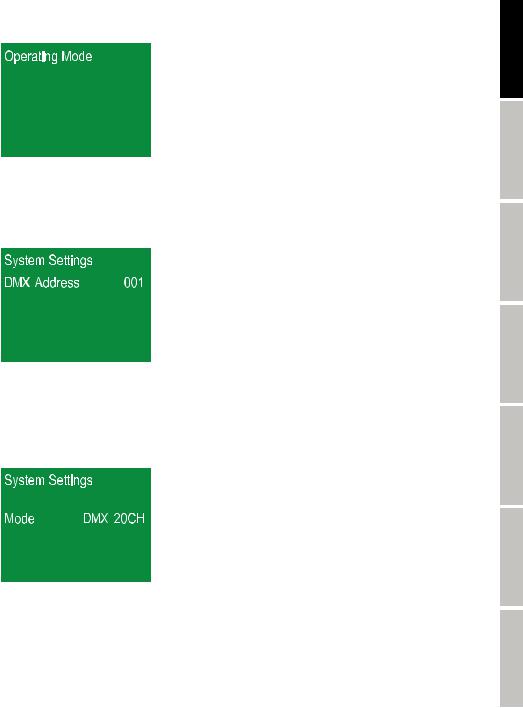
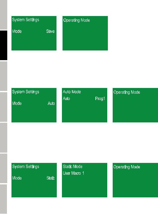
MAIN SCREEN STAND-ALONE MODE
“Operating Mode” is shown in the display’s top row, and the stand-alone operating mode (e.g. Static User Macro 1) is clearly displayed in the middle. The display can also be rotated 180° by pressing the key.
key.
SETTING THE DMX START ADDRESS (DMX Address)
You can access the options menu (System Settings) by pressing MODE. Using the and
and arrow keys, now select the “DMX Address” menu option (dark background) and confirm with ENTER. The three digits indicating the DMX start address will change red. You can then use the
 and
and arrow keys to select the desired DMX start address (hold down the arrow keys to quickly change the value). Confirm the process with ENTER and press MODE to return to the main screen.
SETTING THE OPERATING MODE (Mode)
You can access the options menu (System Settings) by pressing MODE. Using the and
and arrow keys, now select the “Mode” menu option (dark background) and confirm with ENTER. The symbols indicating the operating mode (e.g. DMX 20CH) will change red. You can then use the
 and
and keys to select the desired operating mode. Confirm the process with ENTER and press MODE (repeatedly, if necessary) to return to the main screen.
Operating modes: DMX 17CH, DMX 20CH, Slave, Auto, Static.
ENGLISH
FRANCAIS DEUTSCH
ESPAÑOL
POLSKI
ITALIANO
DMX OPERATING MODE (DMX)
Two different DMX operating modes are available: 17-channel and 20-channel (DMX 17CH, 20CH). The DMX operating modes can be selected as previously described in the section “SETTING THE OPERATING MODE”. DMX tables and channel assignments can be found in these instructions under the section “DMX CONTROL”.
DMX
7
ENGLISH
FRANCAIS DEUTSCH
ESPAÑOL
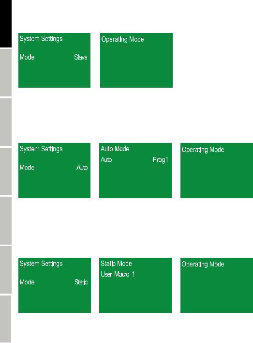
SLAVE MODE (Slave)
The Slave mode can be selected as previously described in the section “SETTING THE OPERATING MODE”. Connect the slave and master unit (same model, same software version) using a DMX cable (Master DMX OUT – Slave DMX IN), and activate one of the stand-alone modes (Auto or Static) on the master unit. The slave unit will now follow the master unit.
AUTO MODE (Prog1–Prog4)
The four different Auto programs each consist of a sequence of hard-coded processes for changing the color, gobo, movement, etc. The Auto mode can be selected as previously described in the section “SETTING THE OPERATING MODE”. After confirming the selection with ENTER, use and
and to select the “Auto” menu option and confirm with ENTER. Now use
 and
and to select one of the four Auto programs (Prog1– Prog4) and then confirm with ENTER. Use
  and
and to select the “Auto Speed” menu option to configure the desired program operating speed. Press ENTER and then use
 and
and to select a value between 000 and 100 (000 = minimum, 100 = maximum speed). Confirm with ENTER and then press MODE three times to return to the main screen.
POLSKI
ITALIANO
DMX
STATIC MODE (Static)
As with a DMX control device, the Static mode makes it possible to configure all functions, such as Pan, Tilt, Color Wheel, Gobo Wheel, and Strobe, with values between 000 and 255 directly on the device. This allows the user to create individual scenes without needing an
additional DMX controller. Four user macros are available for creating individual settings (User Macro 1–4). The Static mode can be selected as previously described in the section “SETTING THE OPERATING MODE”. After you have confirmed the entry with ENTER, select one of the four available macros and then confirm with ENTER. Now you can use the and
and control keys to select functions and effects (see Static list). Press ENTER. Now use
 and
and to select the value (hold down the arrow keys to quickly change the values). Always confirm entries with ENTER. After you’ve configured all the functions and effects as desired, press MODE four times to return to the main screen.
8
Static
Pan |
|
000 |
- |
255 |
0% to 100% |
|
Tilt |
|
000 |
- |
255 |
0% to 100% |
|
Dimmer |
000 |
- |
255 |
0% to 100% |
||
|
|
000 |
- |
005 |
Strobe open |
|
|
|
006 |
- |
010 |
Strobe closed |
|
|
|
011 |
- |
033 |
Pulse random, slow -> fast |
|
|
|
034 |
- |
056 |
Ramp up random, slow -> fast |
|
Strobe |
(multifunctional strobe) |
057 |
- |
079 |
Ramp down random, slow -> fast |
|
|
|
080 |
- |
102 |
Random strobe effect, slow -> fast |
|
|
|
103 |
- |
127 |
Strobe break effect, 5s…..1s (short burst with break) |
|
|
|
128 |
- |
250 |
Strobe slow -> fast <1Hz - 20Hz |
|
|
|
251 |
- |
255 |
Strobe open |
|
|
|
000 |
- |
005 |
Open |
|
|
|
006 |
- |
011 |
Deep Red |
|
|
|
012 |
- |
017 |
Medium Blue |
|
|
|
018 |
- |
023 |
Deep Green |
|
|
|
024 |
- |
029 |
Yellow |
|
Color |
(Color Wheel) |
030 |
- |
035 |
Lavender |
|
036 |
- |
041 |
Amber/Deep Orange |
|||
|
|
|||||
|
|
042 |
- |
047 |
CTO 3200K |
|
|
|
048 |
- |
053 |
Congo Blue |
|
|
|
054 |
- |
192 |
Color Wheel position 0 - 360° |
|
|
|
193 |
- |
223 |
Color Wheel rotation slow -> fast, fwd |
|
|
|
224 |
- |
224 |
Color Wheel rotation stop |
|
|
|
225 |
- |
255 |
Color Wheel rotation fast -> slow, bwd |
|
|
|
000 |
- |
005 |
Open |
|
|
|
006 |
- |
020 |
Gobo 1 |
|
|
|
021 |
- |
035 |
Gobo 2 |
|
|
|
036 |
- |
050 |
Gobo 3 |
|
|
|
051 |
- |
065 |
Gobo 4 |
|
|
|
066 |
- |
080 |
Gobo 5 |
|
|
|
081 |
- |
095 |
Gobo 6 |
|
|
|
096 |
- |
110 |
Gobo 1 shake (slow-fast) |
|
Gobo 1 |
(Gobo Wheel 1) |
111 |
- |
125 |
Gobo 2 shake (slow-fast) |
|
|
|
126 |
- |
140 |
Gobo 3 shake (slow-fast) |
|
|
|
141 |
- |
155 |
Gobo 4 shake (slow-fast) |
|
|
|
156 |
- |
170 |
Gobo 5 shake (slow-fast) |
|
|
|
171 |
- |
185 |
Gobo 6 shake (slow-fast) |
|
|
|
186 |
- |
192 |
Open |
|
|
|
193 |
- |
223 |
Gobo Wheel rotation slow -> fast, fwd |
|
|
|
224 |
- |
224 |
Gobo Wheel rotation stop |
|
|
|
225 |
- |
255 |
Gobo Wheel rotation fast -> slow, bwd |
|
|
|
000 |
- |
005 |
Gobo rotation off |
|
|
|
006 |
- |
127 |
Gobo position 0° ... 540° |
|
Gobo 1 Rot (Gobo 1 rotation) |
128 |
- |
191 |
Gobo rotation slow -> fast, fwd |
||
|
|
192 |
- |
192 |
Gobo rotation stop |
|
|
|
193 |
- |
255 |
Gobo rotation fast -> slow, bwd |
|
ENGLISH
FRANCAIS DEUTSCH
ESPAÑOL
POLSKI
ITALIANO
DMX
9

ENGLISH
FRANCAIS DEUTSCH
ESPAÑOL
POLSKI
ITALIANO
DMX
|
|
|
000 |
- |
005 |
Open |
|
|
|
|
006 |
- |
020 |
Gobo 1 |
|
|
|
|
021 |
- |
035 |
Gobo 2 |
|
|
|
|
036 |
- |
050 |
Gobo 3 |
|
|
|
|
051 |
- |
065 |
Gobo 4 |
|
|
|
|
066 |
- |
080 |
Gobo 5 |
|
|
|
|
081 |
- |
095 |
Gobo 6 |
|
|
|
|
096 |
- |
110 |
Gobo 1 shake slow -> fast |
|
Gobo 2 |
(Gobo Wheel 2) |
111 |
- |
125 |
Gobo 2 shake slow -> fast |
||
|
|
|
126 |
- |
140 |
Gobo 3 shake slow -> fast |
|
|
|
|
141 |
- |
155 |
Gobo 4 shake slow -> fast |
|
|
|
|
156 |
- |
170 |
Gobo 5 shake slow -> fast |
|
|
|
|
171 |
- |
185 |
Gobo 6 shake slow -> fast |
|
|
|
|
186 |
- |
192 |
Open |
|
|
|
|
193 |
- |
223 |
Gobo Wheel rotation slow -> fast, fwd |
|
|
|
|
224 |
- |
224 |
Gobo Wheel rotation stop |
|
|
|
|
225 |
- |
255 |
Gobo Wheel rotation fast -> slow, bwd |
|
Zoom |
|
|
000 |
- |
255 |
Narrow -> wide |
|
Focus |
|
|
000 |
- |
255 |
0% to 100% |
|
|
|
|
000 |
- |
005 |
Prism off (open) |
|
Prism |
(prism selection) |
006 |
- |
127 |
Prism 1 circle |
||
|
|
|
128 |
- |
255 |
Prism 2 linear |
|
|
|
|
000 |
- |
005 |
Prism rotation off |
|
|
|
|
006 |
- |
127 |
Prism position 0 ... 540° |
|
Prism Rot |
(prism rotation) |
128 |
- |
191 |
Prism rotation slow -> fast, fwd |
||
|
|
|
192 |
- |
192 |
Prism rotation stop |
|
|
|
|
193 |
- |
255 |
Prism rotation fast -> slow, bwd |
|
Frost |
|
|
000 |
- |
005 |
No frost |
|
|
|
006 |
- |
255 |
0% to 100% |
||
|
|
|
|||||
|
|
|
000 |
- |
005 |
Off |
|
|
|
|
006 |
- |
040 |
Pan small -> large |
|
|
|
|
041 |
- |
075 |
Tilt small -> large |
|
P/T Macro |
(Pan/Tilt auto movement) |
076 |
- |
110 |
Pan/Tilt small -> large |
||
111 |
- |
145 |
Pan/Tilt (invers) small -> large |
||||
|
|
|
|||||
|
|
|
146 |
- |
180 |
Circle small -> large |
|
|
|
|
181 |
- |
215 |
Circle (invers) small -> large |
|
|
|
|
216 |
- |
255 |
Random small -> large |
|
P/T Speed |
(Pan/Tilt auto movement speed) |
000 |
- |
255 |
Pan/Tilt fast -> slow |
||
10
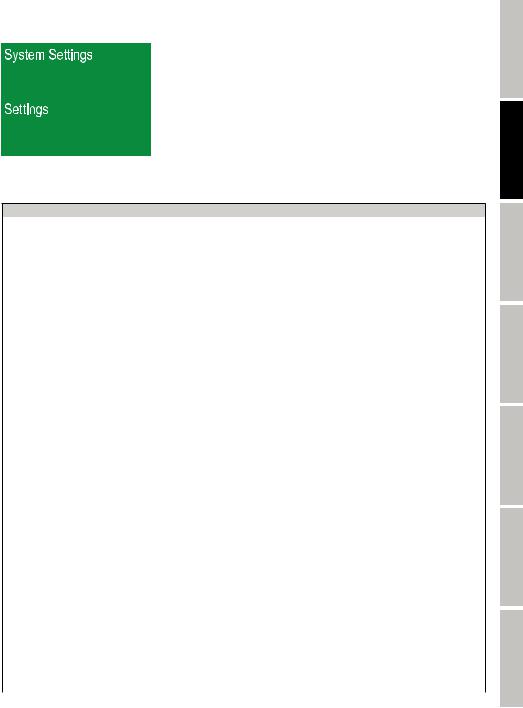
DEVICE SETTINGS (Settings)
You can access the options menu by pressing MODE. Using the and
and control keys, now select the “Settings” menu option (dark background) and confirm with ENTER.
This will take you to the sub-menu for setting the following sub-menu options (select using and
and , confirm with ENTER, change the value or status using
 and
and , and confirm with ENTER):
Settings (bold = factory setting)
Display |
= |
Flip Display |
Off |
Display does not rotate |
|
Rev |
On |
Display rotates by 180° (e.g. when installed overhead) |
|||
|
|
||||
|
|
|
Off |
Deactivates after approx. 30 seconds of inactivity |
|
Display |
= |
Display Backlight |
|
||
|
|
||||
|
|
|
On |
Permanently on |
|
DMX Fail |
= |
Operating mode for DMX |
Hold |
Last command is kept |
|
signal interruption |
Blackout |
Activates blackout |
|||
|
|
||||
|
|
|
Linear |
Light intensity increases linearly with DMX value |
|
|
|
|
“Exp |
Light intensity can be finely adjusted at lower DMX values and |
|
|
|
|
(exponential)” |
broadly adjusted at higher DMX values |
|
DimCurve |
= |
Dimmer Curve |
“Log |
Light intensity can be broadly adjusted at lower DMX values |
|
|
|
|
(logarithmic)” |
and finely adjusted at higher DMX values |
|
|
|
|
S-curve |
Light intensity can be finely adjusted at lower and higher DMX |
|
|
|
|
values and broadly adjusted at medium DMX values |
||
|
|
|
|
||
Pan Angle |
= |
Pan Angle |
540 |
Pan angle 540° |
|
630 |
Pan angle 630° |
||||
|
|
|
|||
Pan Rev |
= |
Pan Reverse |
Off |
Pan movement direction does not reverse |
|
On |
Pan movement direction reverses |
||||
|
|
|
|||
Tilt Rev |
= |
Tilt Reverse |
Off |
Tilt movement direction does not reverse |
|
On |
Tilt movement direction reverses |
||||
|
|
|
|||
|
|
|
800 Hz / 1200 |
Sets the LED PWM frequency |
|
PWM freq |
= |
LED PWM Frequency |
Hz / 2000 Hz / |
|
|
3600 Hz / 12 kHz / |
|
||||
|
|
|
|
||
|
|
|
25 kHz |
|
|
Fan |
= |
Sets fan control |
Auto |
Automatic fan control |
|
Silent |
Extra quiet fan with reduced brightness, if required |
||||
|
|
|
|||
Feedback |
= |
Position correction |
On |
Automatic position correction activated |
|
Off |
Automatic position correction deactivated |
||||
|
|
|
|||
Mov |
= |
Automatic blackout when |
Off |
No blackout when head moves |
|
Blackout |
head moves |
On |
Blackout when head moves |
||
|
|||||
|
|
|
Off |
Stops the function test |
|
Test |
= |
Function test |
On |
Step-by-step function test of the LED and all motors (pan, tilt, |
|
|
|
|
gobo, etc.) |
||
|
|
|
|
||
Factory |
= |
Reset to factory settings |
Reset? |
Reset to factory settings: |
|
Reset |
Confirm with ENTER, cancel with MODE |
||||
|
|
|
|||
|
|
|
Pan&Tilt |
Reset the pan and tilt motors |
|
Reset |
= |
Reset the motors |
Head |
Reset all head motors (color wheel, gobo well, prism, etc.) |
|
|
|||||
|
|
|
|
|
|
|
|
|
All |
Reset all motors |
ENGLISH
FRANCAIS DEUTSCH
ESPAÑOL
POLSKI
ITALIANO
DMX
11
ENGLISH
FRANCAIS DEUTSCH
ESPAÑOL
POLSKI
ITALIANO
DMX
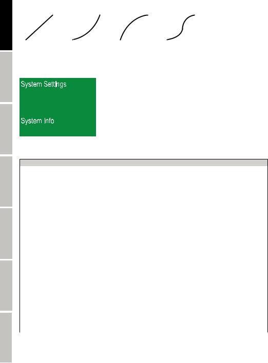
Dimmer curves |
|
|
|
|
|
|
|
|
|
|
|
|
|
|
|
|
|
|
|||||
|
|
Linear |
|
Exponential |
|
Logarithmic |
|
|
S-curve |
||||||||||||||
|
|
|
|
|
|
|
|
|
|
|
|
|
|
|
|
|
|
|
|
|
|
|
|
Light intensity |
|
|
|
|
|
Light intensity |
|
|
|
|
|
Light intensity |
|
|
|
|
|
Light intensity |
|
|
|
|
|
|
|
|
|
|
|
|
|
|
|
|
|
|
|
|
|
|
|
|
|
||||
|
|
|
|
|
|
|
|
|
|
|
|
|
|
|
|||||||||
|
|
|
|
|
|
|
|
|
|
|
|
|
|
|
|||||||||
|
|
|
|
|
|
|
|
|
|
|
|
|
|
|
|||||||||
|
|
|
|
|
|
|
|
|
|
|
|
|
|
|
|||||||||
|
|
|
|
|
|
|
|
|
|
|
|
|
|
|
|
|
|
|
|
||||
|
DMX value |
|
DMX value |
|
DMX value |
|
DMX value |
||||||||||||||||
SYSTEM INFORMATION (System info)
You can access the options menu by pressing MODE. Using the and
and control keys, now select the “System Info” menu option (dark background) and confirm with ENTER.
This will take you to the sub-menu for displaying the device information (select using and
and , press ENTER to display information):
System Info
|
|
|
1U: |
Vx.xx |
|
Firmware |
= |
Displays the device firmware |
2U: |
Vx.xx |
|
|
|
|
3U: |
Vx.xx |
|
Tempera- |
|
|
LED Temp |
xxx°C/°F |
|
= |
Temperature display |
|
Celsius |
||
ture |
Temp Unit |
||||
|
|
Fahrenheit |
|||
|
|
|
|
||
Fan |
= |
Speed display |
Fan1: |
xxxx RPM |
|
Fan2: |
xxxx RPM |
||||
|
|
|
|||
|
|
|
Total: |
Displays the total operating time in hours and minutes |
|
Time Info |
= |
Displays operating time |
Current: |
Displays the current operating time in hours and minutes |
|
|
|
|
Last: |
Displays the last operating time in hours and minutes |
|
|
|
|
PAN |
Solution: Reset Pan&Tilt |
|
|
|
|
TILT |
Solution: Reset Pan&Tilt |
|
|
|
|
Gobo Wheel 1 |
Solution: Reset head. If necessary, check that it is secured |
|
|
|
|
and positioned properly |
||
|
|
|
|
||
|
|
Functional error display |
Gobo Wheel 1 Rot |
Solution: Reset head. If necessary, check that it is secured |
|
|
|
and positioned properly |
|||
|
|
If it is not possible to |
|
||
|
|
Gobo Wheel 2. |
Solution: Reset head |
||
|
|
eliminate a functional error |
|||
Error Info |
= |
by resetting or restarting, the |
Color Wheel |
Solution: Reset head |
|
|
|
faulty unit must be repaired |
Focus |
Solution: Reset head |
|
|
|
by an authorized service |
Zoom |
Solution: Reset head |
|
|
|
center. |
|||
|
|
Prism Red |
Solution: Reset head |
||
|
|
|
|||
|
|
|
Fan 1 |
Solution: Restart |
|
|
|
|
Fan 2 |
Solution: Restart |
|
|
|
|
Temperature |
Solution: Allow to cool, restart if necessary. Check maximum |
|
|
|
|
ambient temperature (40°C) |
||
|
|
|
|
12
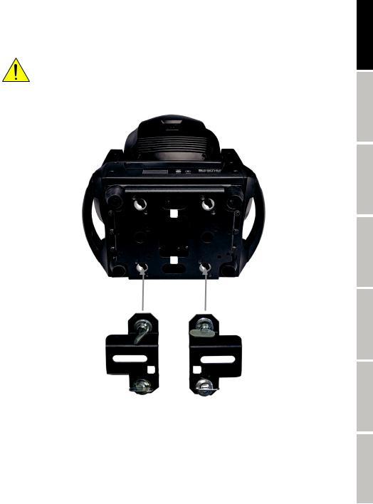
SETUP AND INSTALLATION
The integrated rubber feet allow the spotlight to be placed in a suitable position on a level surface. Install on a crossbeam using two omega brackets that are attached to the bottom of the device’s base (A). Two omega brackets are included in the scope of delivery; suitable crossbeam clamps are available as needed. Make sure that the spotlight is firmly attached and secure it to one of the designated locations
(B) with a suitable safety cable.
Important safety information:Overhead installation requires extensive experience, which includes calculating the limit values of the working load, of the installation material to be used, and regularly conducting safety inspections of all installation materials and spotlights. If you do not have these qualifications, do not attempt to carry out the installation yourself; contact a professional company.
B
B
ENGLISH
FRANCAIS DEUTSCH
ESPAÑOL
POLSKI
A A
ITALIANO
DMX
13
ENGLISH
FRANCAIS DEUTSCH
ESPAÑOL
POLSKI
ITALIANO
DMX
DMX TECHNOLOGY
DMX-512
DMX (Digital Multiplex) is the designation for a universal transmission protocol for communications between corresponding devices and controllers. A DMX controller sends DMX data to the connected DMX device(s). The DMX data is always transmitted as a serial data stream that is forwarded from one connected device to the next via the "DMX IN" and "DMX OUT" connectors (XLR plug-type connectors) that are found on every DMX-capable device, provided the maximum number of devices does not exceed 32 units. The last device in the chain needs to be equipped with a terminator (terminating resistor).
DMX CONNECTION
DMX is the common "language" via which a very wide range of types and models of equipment from various manufacturers can be connected with one another and controlled via a central controller, provided that all of the devices and the controller are DMX
compatible. For optimum data transmission, it is necessary to keep the connecting cables between the individual devices as short as possible. The order in which the devices are integrated in the DMX network has no influence on the addresses. Thus the device with the DMX address 1 can be located at any position in the (serial) DMX chain: at the beginning, at the end or somewhere in the middle. If the DMX address 1 is assigned to a device, the controller "knows" that it should send all data allocated to address 1 to this device regardless of its position in the DMX network.
SERIAL CONNECTION OF MULTIPLE LIGHTS
1.Connect the male XLR connector (3-pin or 5-pin) of the DMX cable to the DMX output (female XLR socket) of the first DMX device (e.g. DMX-Controller).
2.Connect the female 3-pin XLR connector of the DMX cable connected to the first projector to the DMX input (male 3-pin socket) of the next DMX device. In the same way, connect the DMX output of this device to the DMX input of the next device and repeat until all devices have been connected. Please note that as a rule, DMX devices are connected in series and connections cannot be shared without active splitters. The maximum number of DMX devices in a DMX chain should not exceed 32 units.
The Adam Hall 3 STAR, 4 STAR, and 5 STAR product ranges include an extensive selection of suitable cables.
DMX CABLES
When fabricating your own cables, always observe the illustrations on this page. Never connect the shielding of the cable to the ground contact of the plug, and always make certain that the shielding does not come into contact with the housing of the XLR plug. If the shielding is connected to the ground, this can lead to short-circuiting and system malfunctions.
Pin Assignment |
|
|
|
|
|
|
DMX cable with 3-pin XLR connectors: |
DMX cable with 5-pin XLR connectors (pin 4 and 5 are not used): |
|||||
1 |
Shield |
1 |
5 |
4 |
4 |
5 |
3 |
|
3 |
|
3 |
3 |
|
|
1 |
2 |
2 |
|
||
2 |
|
2 |
1 |
|||
|
|
|
|
|
Shield |
|
DMX TERMINATORS (TERMINATING RESISTORS)
To prevent system errors, the last device in a DMX chain needs to be equipped with a terminating resistor (120 ohm, 1/4 Watt). 3-pin XLR connector with a terminating resistor: K3DMXT3
5-pin XLR connector with a terminating resistor: K3DMXT5
Pin Assignment |
|
|
|
3-pin XLR connector: |
5-pin XLR connector: |
||
|
1 |
4 |
5 |
3 |
|
|
|
2 |
32 |
1 |
|
|
|
|
|
DMX ADAPTER
The combination of DMX devices with 3-pin connectors and DMX devices with 5-pin connectors in a DMX chain is possible with suitable adapters.
Pin Assignment
DMX Adapter 5-pin XLR male to 3-pin XLR female: K3DGF0020
Pins 4 and 5 are not used.
Pin Assignment
DMX Adapter 3-pin XLR male to 5-pin XLR female: K3DHM0020
Pins 4 and 5 are not used.
14
TECHNICAL SPECIFICATIONS
Article number: |
CLASZ300 |
Product type: |
LED moving light |
Type: |
Moving head |
LED color spectrum: |
Cold white 19500 K |
Number of LEDs: |
1 |
LED type: |
200 W |
Number of colors: |
8+ open and continuously adjustable color wheel positions |
Number of gobos: |
6 fixed + 6 rotating and indexable + open |
Refresh rate: |
800 Hz; 1200 Hz; 2000 Hz; 3600 Hz; 12 kHz; 25 kHz |
Beam angle: |
10°–20° |
DMX input: |
3-pin XLR male |
|
5-pin XLR male |
DMX output: |
3-pin XLR female |
|
5-pin XLR female |
DMX mode: |
17-channel, 20-channel |
DMX functions: |
Pan/Tilt, Slight Pan/Tilt, Dimmer, Strobe, Color Wheel, Fixed Gobo Wheel, Rotating Gobo Wheel, |
|
Shaking Gobo, 2 x Prisms, Focus, Frost, Zoom, Moving Macro, Auto Programs, Device Settings |
Stand-alone functions: |
Auto Program, User Macros, Master/Slave Mode |
Controller: |
DMX512, RDM-enabled |
Pan angle: |
540°/630° |
Tilt angle: |
270° |
Control elements: |
Mode, Enter, four arrow keys |
Display elements: |
Backlit color LC display, battery-powered to configure system settings without being connected to |
|
power (automatic battery recharging) |
Operating voltage: |
100–240V AC / 50–60 Hz |
Power consumption: |
320 W |
Illuminance (@ 1 m): |
162000 lx |
Luminous flux: |
7500 lm |
Power supply connection: |
Neutrik powerCON in and out (max. output current 9 A) |
Fuse: |
T4AL / 250 V (0.2 x 0.8 inches) |
Ambient temperature (running): |
32°F–104°F |
Relative humidity: |
< 85%, non-condensing |
Housing material: |
Metal, ABS |
Housing color: |
Black |
Housing cooling: |
Temperature-controlled fans |
Dimensions (W x H x D, without |
11.1 x 18.5 x 73.2 inches |
mounting bracket): |
|
Weight: |
25 lbs |
Additional features: |
1 m power cord with Neutrik powerCON plug |
|
and two omega mounting brackets included in delivery, one exchangeable gobo wheel |
ENGLISH
FRANCAIS DEUTSCH
ESPAÑOL
POLSKI
ITALIANO
DMX
15

ENGLISH
FRANCAIS DEUTSCH
ESPAÑOL
POLSKI
ITALIANO
DMX
MANUFACTURER´S DECLARATIONS
MANUFACTURER‘S WARRANTY & LIMITATIONS OF LIABILITY
You can find our current warranty conditions and limitations of liability at: https://cdn-shop.adamhall.com/media/pdf/MANUFACTU- RERS-DECLARATIONS_CAMEO.pdf. To request warranty service for a product, please contact Adam Hall GmbH, Adam-Hall-Str. 1, 61267 Neu Anspach / Email: Info@adamhall.com / +49 (0)6081 / 9419-0.
CORRECT DISPOSAL OF THIS PRODUCT
(valid in the European Union and other European countries with a differentiated waste collection system)
 This symbol on the product, or on its documents indicates that the device may not be treated as household waste. This is to avoid environmental damage or personal injury due to uncontrolled waste disposal. Please dispose of this product separately from other waste and have it recycled to promote sustainable economic activity. Household users should contact either the retailer where they purchased this product, or their local government office, for details on where and how they can recycle this item in an environmentally friendly manner. Business users should contact their supplier and check the terms and conditions of the purchase contract. This product should not be mixed with other commercial waste for disposal.
FCC STATEMENT
This device complies with Part 15 of the FCC Rules. Operation is subject to the following two conditions:
(1)This device may not cause harmful interference, and
(2)This device must accept any interference received, including interference that may cause undesired operation
CE Compliance
Adam Hall GmbH states that this product meets the following guidelines (where applicable):
R&TTE (1999/5/EC) or RED (2014/53/EU) from June 2017
Low voltage directive (2014/35/EU)
EMV directive (2014/30/EU)
RoHS (2011/65/EU)
The complete declaration of conformity can be found at www.adamhall.com.
Furthermore, you may also direct your enquiry to info@adamhall.com.
16

DEUTSCH
SIE HABEN DIE RICHTIGE WAHL GETROFFEN!
Dieses Gerät wurde unter hohen Qualitätsanforderungen entwickelt und gefertigt, um viele Jahre einen reibungslosen Betrieb zu gewährleisten. Bitte lesen Sie diese Bedienungsanleitung sorgfältig, damit Sie Ihr neues Produkt von Cameo Light schnell und optimal einsetzen können. Weitere Informationen über Cameo Light erhalten Sie auf unserer Website WWW.CAMEOLIGHT.COM.
SICHERHEITSHINWEISE
1.Lesen Sie diese Anleitung bitte sorgfältig durch.
2.Bewahren Sie alle Informationen und Anleitungen an einem sicheren Ort auf.
3.Befolgen Sie die Anweisungen.
4.Beachten Sie alle Warnhinweise. Entfernen Sie keine Sicherheitshinweise oder andere Informationen vom Gerät.
5.Verwenden Sie das Gerät nur in der vorgesehenen Art und Weise.
6.Verwenden Sie ausschließlich stabile und passende Stative bzw. Befestigungen (bei Festinstallationen). Stellen Sie sicher,
dass Wandhalterungen ordnungsgemäß installiert und gesichert sind. Stellen Sie sicher, dass das Gerät sicher installiert ist und nicht herunterfallen kann.
7.Beachten Sie bei der Installation die für Ihr Land geltenden Sicherheitsvorschriften.
8.Installieren und betreiben Sie das Gerät nicht in der Nähe von Heizkörpern, Wärmespeichern, Öfen oder sonstigen Wärmequellen. Sorgen Sie dafür, dass das Gerät immer so installiert ist, dass es ausreichend gekühlt wird und nicht überhitzen kann.
9.Platzieren Sie keine Zündquellen wie z.B. brennende Kerzen auf dem Gerät.
10.Lüftungsschlitze dürfen nicht blockiert werden.
11.Das Gerät wurde ausschließlich für die Verwendung in Innenräumen entwickelt, betreiben Sie das Gerät nicht in unmittelbarer Nähe von Wasser (gilt nicht für spezielle Outdoor Geräte - beachten Sie in diesem Fall bitte die im Folgenden vermerkten Sonderhinweise). Bringen Sie das Gerät nicht mit brennbaren Materialien, Flüssigkeiten oder Gasen in Berührung.
12.Sorgen Sie dafür, dass kein Tropfoder Spritzwasser in das Gerät eindringen kann. Stellen Sie keine mit Flüssigkeit gefüllten Behältnisse wie Vasen oder Trinkgefäße auf das Gerät.
13.Sorgen Sie dafür, dass keine Gegenstände in das Gerät fallen können.
14.Betreiben Sie das Gerät nur mit dem vom Hersteller empfohlenen und vorgesehenen Zubehör.
15.Öffnen Sie das Gerät nicht und verändern Sie es nicht.
16.Überprüfen Sie nach dem Anschluss des Geräts alle Kabelwege, um Schäden oder Unfälle, z. B. durch Stolperfallen zu vermeiden.
17.Achten Sie beim Transport darauf, dass das Gerät nicht herunterfallen und dabei möglicherweise Sachund Personenschäden verursachen kann.
18.Wenn Ihr Gerät nicht mehr ordnungsgemäß funktioniert, Flüssigkeiten oder Gegenstände in das Geräteinnere gelangt sind, oder das Gerät anderweitig beschädigt wurde, schalten Sie es sofort aus und trennen es von der Netzsteckdose (sofern es sich um ein aktives Gerät handelt). Dieses Gerät darf nur von autorisiertem Fachpersonal repariert werden.
19.Verwenden Sie zur Reinigung des Geräts ein trockenes Tuch.
20.Beachten Sie alle in Ihrem Land geltenden Entsorgungsgesetze. Trennen Sie bei der Entsorgung der Verpackung bitte Kunststoff und Papier bzw. Kartonagen voneinander.
21.Kunststoffbeutel müssen außer Reichweite von Kindern aufbewahrt werden.
BEI GERÄTEN MIT NETZANSCHLUSS:
22.ACHTUNG: Wenn das Netzkabel des Geräts mit einem Schutzkontakt ausgestattet ist, muss es an einer Steckdose mit Schutzleiter angeschlossen werden. Deaktivieren Sie niemals den Schutzleiter eines Netzkabels.
23.Schalten Sie das Gerät nicht sofort ein, wenn es starken Temperaturschwankungen ausgesetzt war (beispielsweise nach dem Transport). Feuchtigkeit und Kondensat könnten das Gerät beschädigen. Schalten Sie das Gerät erst ein, wenn es Zimmertemperatur erreicht hat.
24.Bevor Sie das Gerät an die Steckdose anschließen, prüfen Sie zuerst, ob die Spannung und die Frequenz des Stromnetzes mit den auf dem Gerät angegebenen Werten übereinstimmen. Verfügt das Gerät über einen Spannungswahlschalter, schließen Sie das Gerät nur an die Steckdose an, wenn die Gerätewerte mit den Werten des Stromnetzes übereinstimmen. Wenn das mitgelieferte Netzkabel bzw. der mitgelieferte Netzadapter nicht in Ihre Netzsteckdose passt, wenden Sie sich an Ihren Elektriker.
25.Treten Sie nicht auf das Netzkabel. Sorgen Sie dafür, dass spannungsführende Kabel speziell an der Netzbuchse bzw. am Netzadapter und der Gerätebuchse nicht geknickt werden.
26.Achten Sie bei der Verkabelung des Geräts immer darauf, dass das Netzkabel bzw. der Netzadapter stets frei zugänglich ist. Trennen Sie das Gerät stets von der Stromzuführung, wenn das Gerät nicht benutzt wird, oder Sie das Gerät reinigen möchten. Ziehen Sie Netzkabel und Netzadapter immer am Stecker bzw. am Adapter und nicht am Kabel aus der Steckdose. Berühren Sie Netzkabel und Netzadapter niemals mit nassen Händen.
27.Schalten Sie das Gerät möglichst nicht schnell hintereinander ein und aus, da sonst die Lebensdauer des Geräts beeinträchtigt werden könnte.
28.WICHTIGER HINWEIS: Ersetzen Sie Sicherungen ausschließlich durch Sicherungen des gleichen Typs und Wertes. Sollte eine Sicherung wiederholt auslösen, wenden Sie sich bitte an ein autorisiertes Servicezentrum.
29.Um das Gerät vollständig vom Stromnetz zu trennen, entfernen Sie das Netzkabel bzw. den Netzadapter aus der Steckdose.
30.Wenn Ihr Gerät mit einem Volex-Netzanschluss bestückt ist, muss der passende Volex-Gerätestecker entsperrt werden, bevor er entfernt werden kann. Das bedeutet aber auch, dass das Gerät durch ein Ziehen am Netzkabel verrutschen und herunterfallen kann, wodurch Personen verletzt werden und/oder andere Schäden auftreten können. Verlegen Sie Ihre Kabel daher immer sorgfältig.
31.Entfernen Sie Netzkabel und Netzadapter aus der Steckdose bei Gefahr eines Blitzschlags oder wenn Sie das Gerät länger nicht verwenden.
32.Das Gerät darf nur im spannungsfreien Zustand (Trennung des Netzsteckers vom Stromnetz) installiert werden.
ENGLISH
FRANCAIS DEUTSCH
ESPAÑOL
POLSKI
ITALIANO
DMX
17
ENGLISH
FRANCAIS DEUTSCH
ESPAÑOL
POLSKI
ITALIANO
DMX
33.Staub und andere Ablagerungen im Inneren des Geräts können es beschädigen. Das Gerät sollte je nach Umgebungsbedingungen (Staub, Nikotin, Nebel etc.) regelmäßig von qualifiziertem Fachpersonal gewartet bzw. gesäubert werden (keine Garantieleistung), um Überhitzung und Fehlfunktionen zu vermeiden.
34.Der Abstand zu brennbaren Materialien muss mindestens 0,5 m betragen.
35.Netzleitungen zur Spannungsversorgung mehrerer Geräte müssen mindestens 1,5 mm² Aderquerschnitt aufweisen. In der EU müssen die Leitungen H05VV-F, oder gleichartig, entsprechen. Geeignete Leitungen werden von Adam Hall angeboten. Mit diesen Leitungen können Sie mehrere Geräte über den Power out Anschluss mit dem Power IN Anschluss eines weiteren Gerätes verbinden. Beachten Sie, dass die gesamte Stromaufnahme aller angeschlossenen Geräte den vorgegebenen Wert nicht überschreitet (Aufdruck auf dem Gerät). Achten Sie darauf, Netzleitungen so kurz wie möglich zu halten.
ACHTUNG
Entfernen Sie niemals die Abdeckung, da sonst das Risiko eines elektrischen Schlages besteht.

 Im Inneren des Geräts befinden sich keine Teile, die vom Bediener repariert oder gewartet werden
  können. Lassen Sie Wartung und Reparaturen ausschließlich von qualifiziertem Servicepersonal durchführen.
Das gleichseitige Dreieck mit Blitzsymbol warnt vor nichtisolierten, gefährlichen Spannungen im Geräteinneren, die einen elektrischen Schlag verursachen können.
Das gleichseitige Dreieck mit Ausrufungszeichen kennzeichnet wichtige Bedienungsund Wartungshinweise.
Warnung! Dieses Symbol kennzeichnet heiße Oberflächen. Während des Betriebs können bestimmte Teile des Gehäuses heiß werden. Berühren oder transportieren Sie das Gerät nach einem Einsatz erst nach einer Abkühlzeit von mindestens 10 Minuten.
Warnung! Dieses Gerät ist für eine Nutzung bis zu einer Höhe von maximal 2000 Metern über dem Meeresspiegel bestimmt.
Warnung! Dieses Gerät ist nicht für den Einsatz in tropischen Klimazonen bestimmt.
Vorsicht! Intensive LED Lichtquelle! Gefahr der Augenschädigung. Nicht in die Lichtquelle blicken.
VORSICHT! WICHTIGE HINWEISE IN BEZUG AUF LICHT-PRODUKTE!
1.Das Produkt ist für den professionellen Einsatz im Bereich der Veranstaltungstechnik entwickelt worden und ist nicht für die Raumbeleuchtung in Haushalten geeignet.
2.Blicken Sie niemals, auch nicht kurzzeitig, direkt in den Lichtstrahl.
3.Blicken Sie niemals mit optischen Geräten wie Vergrößerungsgläsern in den Lichtstrahl.
4.Stroboskopeffekte können unter Umständen bei empfindlichen Menschen epileptische Anfälle auslösen! Epilepsiekranke Menschen sollten daher unbedingt Orte meiden, an denen Stroboskopeffekte eingesetzt werden.
18
EINFÜHRUNG
LED MOVING HEAD AURO SPOT ZOOM 300
CLASZ300
STEUERUNGSFUNKTIONEN:
17-Kanal und 20-Kanal DMX-Steuerung Master / Slave Betrieb
Stand-Alone Funktionen
EIGENSCHAFTEN:
LED Moving Head mit einer 200W LED. Farbrad und 2 Goboräder. Zoom-Funktion. Fokus. Frost-Filter. 2 Prismen. 2 DMX-Modi. DMX-512 Steuerung. Master / Slave Betrieb. Stand-Alone Funktionen. 2 Omega-Brackets inklusive. Betriebsspannung 100V - 240V AC / 50 - 60Hz. Leistungsaufnahme 320W.
Der Scheinwerfer verfügt über den RDM-Standard (Remote Device Management). Diese Gerätefernverwaltung ermöglicht die Statusabfrage und Konfiguration von RDM-Endgeräten über einen RDM-fähigen Controller.
ANSCHLÜSSE, BEDIENUND ANZEIGEELEMENTE
ENGLISH
DEUTSCH
1 |
4 |
5 |
|
3 |
|
|
6 |
7 |
FRANCAIS
1 POWER IN
Neutrik powerCON Netzeingangsbuchse. Betriebsspannung 100 - 240V AC / 50 - 60Hz. Ein geeignetes Netzkabel befindet sich im Lieferumfang.
2 POWER OUT
Neutrik powerCON Netzausgangsbuchse. Dient der Netzversorgung weiterer CAMEO Scheinwerfer. Achten Sie darauf, dass die gesamte Stromaufnahme aller angeschlossenen Geräte den auf dem Gerät in Ampere (A) angegebenen Wert nicht überschreitet.
3 SICHERUNGSHALTER
WICHTIGER HINWEIS: Ersetzen Sie die Sicherung ausschließlich durch eine Sicherung des gleichen Typs und mit gleichen Werten. Sollte die Sicherung wiederholt auslösen, wenden Sie sich bitte an ein autorisiertes Servicezentrum.
4 DMX IN
Männliche 3-Pol XLR-Buchse zum Anschließen eines DMX-Kontrollgeräts (z.B. DMX-Pult).
5 DMX OUT
Weibliche 3-Pol XLR-Buchse zum Weiterleiten des DMX-Steuersignals.
6 DMX IN
Männliche 5-Pol XLR-Buchse zum Anschließen eines DMX-Kontrollgeräts (z.B. DMX-Pult).
7 DMX OUT
Weibliche 5-Pol XLR-Buchse zum Weiterleiten des DMX-Steuersignals.
ESPAÑOL
POLSKI
ITALIANO
DMX
19
ENGLISH
8 |
9 |
FRANCAIS DEUTSCH
ESPAÑOL
POLSKI
ITALIANO
DMX
8 BELEUCHTETES LC-DISPLAY
Zeigt den aktuell aktivierten Betriebsmodus, das Auswahlmenü und weitere Systeminformationen an. Nach circa 1 Minute Inaktivität wechselt die Anzeige im Display automatisch zur Hauptanzeige.
9 BEDIENTASTEN
MODE
Durch Drücken der MODE-Taste gelangen Sie in das Auswahlmenü. Durch wiederholtes Drücken gelangen Sie zurück zur Hauptanzeige. Wenn Sie die MODE-Taste betätigen, ohne eine Wertbzw. Statusänderung durch Drücken auf ENTER zu bestätigen, wird der zuvor bestätigte Wert bzw. Status wiederhergestellt.
PFEILTASTEN  UND
UND 
Auswählen der einzelnen Menüpunkte im Auswahlmenü für Systemeinstellungen (DMX-Adresse, Betriebsart usw.) und in den Untermenüs.
ENTER
Durch Drücken der ENTER-Taste gelangen Sie auf die Menüebene um Wertänderungen vornehmen zu können und um eines der Untermenüs zu erreichen. Wertänderungen bestätigen Sie ebenfalls durch Drücken der ENTER-Taste.
PFEILTASTEN  UND
UND 
Ermöglichen es, den Wert in einem Menüpunkt, wie z.B. die DMX-Adresse, wunschgemäß zu verändern.
BATTERIEGESPEISTES DISPLAY
Selbst wenn das Gerät nicht am Stromnetz angeschlossen ist, können Dank des batteriegespeisten Displays Systemeinstellungen netzunabhängig vorgenommen werden. Drücken und halten Sie hierfür die MODE-Taste für eine Dauer von circa 4 Sekunden. Die DMX-Einheit des Scheinwerfers wird in diesem Fall nicht aktiviert. Aus diesem Grund wird, auch wenn ein DMX-Signal am DMX-Eingang anliegt, im Display angezeigt, dass kein DMX-Signal anliegt.
BEDIENUNG
HINWEISE
Sobald der Scheinwerfer korrekt am Stromnetz angeschlossen ist, werden während des Startvorgangs und des Motoren-Resets nacheinander „Software Update Please Wait...“ (nur für Servicezwecke) und das CAMEO Logo im Display angezeigt. Nach diesem Vorgang ist der Scheinwerfer betriebsbereit und die Betriebsart, die zuvor angewählt war, wird aktiviert.
HAUPTANZEIGE DMX BETRIEBSART
In der oberen Zeile des Displays wird der DMX Modus (DMX 17CH, 20CH) und gut sichtbar in der Mitte die DMX-Startadresse angezeigt. Sobald das DMX-Signal unterbrochen wird, wechselt die Hintergrundfarbe des Displays auf Rot und „No DMX“ wird angezeigt, liegt das DMX-Signal wieder an, wechselt das Display wieder zur Hauptanzeige. Die Display-Anzeige kann um 180° gedreht werden, indem Sie die „Pfeil nach rechts“-Taste betätigen.
20
HAUPTANZEIGE STANDALONE BETRIEBSART
In der oberen Zeile des Displays wird „Operating Mode“ und gut sichtbar in der Mitte die Standalone Betriebsart angezeigt (im Beispiel Static User Macro 1). Die Display-Anzeige kann um 180° gedreht werden, indem Sie die „Pfeil nach rechts“-Taste betätigen.
DMX-STARTADRESSE EINSTELLEN (DMX Address)
Durch Drücken der MODE-Taste gelangen Sie in das Auswahlmenü (System Settings). Mit Hilfe der Pfeiltasten und
und wählen Sie nun den Menüpunkt „DMX Address“ aus (dunkel hinterlegt) und bestätigen mit ENTER. Die 3 Ziffern, die die DMX-Startadresse anzeigen, wechseln ihre Farbe auf Rot und Sie können mit Hilfe der Pfeiltasten
 und
und die gewünschte DMX-Startadresse einstellen (Pfeiltasten gedrückt halten für schnelle Wertänderung). Bestätigen Sie den Vorgang mit ENTER und drücken die MODE-Taste, um zur Hauptanzeige zurückzugelangen.
BETRIEBSART EINSTELLEN (Mode)
Durch Drücken der MODE-Taste gelangen Sie in das Auswahlmenü (System Settings). Mit Hilfe der Pfeiltasten und
und wählen Sie nun den Menüpunkt „Mode“ aus (dunkel hinterlegt) und bestätigen mit ENTER. Die Zeichen, die die Betriebsart anzeigen (im Beispiel DMX 20CH), wechseln ihre Farbe auf Rot und Sie können jetzt mit Hilfe der Tasten
 und
und die gewünschte Betriebsart auswählen. Bestätigen Sie den Vorgang mit ENTER und drücken ggf. mehrfach die MODE-Taste, um zur Hauptanzeige zurückzugelangen.
Betriebsarten: DMX 17CH, DMX 20CH, Slave, Auto, Static.
DMX-BETRIEBSART (DMX)
Zwei verschiedene DMX-Betriebsarten stehen zur Auswahl: 17-Kanal und 20-Kanal (DMX 17CH, 20CH). Die Auswahl der DMX-Betriebsarten erfolgt wie zuvor unter Punkt BETRIEBSART EINSTELLEN beschrieben. DMX-Tabellen mit den Kanalbelegungen finden Sie in dieser Anleitung unter DMX STEUERUNG.
ENGLISH
FRANCAIS DEUTSCH
ESPAÑOL
POLSKI
ITALIANO
DMX
21
ENGLISH
FRANCAIS DEUTSCH
ESPAÑOL
SLAVE-BETRIEB (Slave)
Die Auswahl der Slave-Betriebsart erfolgt wie zuvor unter Punkt BETRIEBSART EINSTELLEN beschrieben. Verbinden Sie die Slaveund die Master-Einheit (gleiches Modell, gleicher Softwarestand) mit Hilfe eines DMX-Kabels (Master DMX OUT - Slave DMX IN) und aktivieren in der Master-Einheit eine der Stand-Alone Betriebsarten Auto oder Static. Nun folgt die Slave-Einheit der Master-Einheit.
AUTO-BETRIEBSART (Prog1 - Prog4)
Die vier verschiedenen Auto-Programme bestehen jeweils aus einer Abfolge fest programmierter Farbwechsel-, Gobowechselund Bewegungsabläufen, etc.. Die Auswahl der Auto-Betriebsart erfolgt wie zuvor unter Punkt BETRIEBSART EINSTELLEN beschrieben. Nachdem Sie die Auswahl mit ENTER bestätigt haben, wählen Sie mit Hilfe von und
und den Menüpunkt „Auto“ aus und bestätigen mit ENTER. Wählen Sie nun mit Hilfe von
 und
und eines der vier Auto-Programme aus (Prog1 - Prog4) und bestätigen mit ENTER. Um die Programm-Lauf- geschwindigkeit wunschgemäß einzustellen, wählen Sie jetzt mit Hilfe von
 und
und den Menüpunkt „Auto Speed“ aus. Drücken Sie auf ENTER und stellen einen Wert von 000 bis 100 mit Hilfe von
 und
und ein (000 = minimale, 100 = maximale Geschwindigkeit). Bestätigen Sie mit ENTER und drücken 3x auf MODE, um zur Hauptanzeige zurückzugelangen.
POLSKI
ITALIANO
DMX
STATISCHER MODUS (Static)
Der statische Modus ermöglicht es, ähnlich wie mit einem DMX-Steuergerät, alle Funktionen und Effekte, wie z.B. Pan, Tilt, Farb-, Goborad und Stroboskop, direkt am Gerät mit Werten von 000 bis 255 einzustellen. Somit kann eine individuelle Szene erstellt werden, ohne einen zusätzlichen DMX-Controller zu benötigen. Vier Benutzermakros stehen für individuelle Einstellungen zur Verfügung (User Macro 1 - 4). Die Auswahl der Betriebsart Static erfolgt wie zuvor unter Punkt BETRIEBSART EINSTELLEN beschrieben. Nachdem Sie mit ENTER bestätigt haben, wählen Sie eines der vier verfügbaren Makros zum Bearbeiten aus und bestätigen mit ENTER. Nun können die Funktionen und Effekte mit Hilfe der Bedienfelder und
und angewählt werden (siehe Liste Static). Drücken Sie auf ENTER. Der Wert kann jetzt mit Hilfe von
 und
und verändert werden (Pfeiltasten gedrückt halten für schnelle Wertänderung). Bestätigen Sie Eingaben immer mit ENTER. Nachdem alle Funktionen und Effekte wunschgemäß eingestellt wurden, drücken Sie 4x auf MODE, um zurück zur Hauptanzeige zu gelangen.
22
Static
Pan |
|
000 |
- |
255 |
0% to 100% |
|
Tilt |
|
000 |
- |
255 |
0% to 100% |
|
Dimmer |
000 |
- |
255 |
0% to 100% |
||
|
|
000 |
- |
005 |
Strobe open |
|
|
|
006 |
- |
010 |
Strobe closed |
|
|
|
011 |
- |
033 |
Pulse random, slow -> fast |
|
|
|
034 |
- |
056 |
Ramp up random, slow -> fast |
|
Strobe |
(multifunctional strobe) |
057 |
- |
079 |
Ramp down random, slow -> fast |
|
|
|
080 |
- |
102 |
Random strobe effect, slow -> fast |
|
|
|
103 |
- |
127 |
Strobe break effect, 5s…..1s (short burst with break) |
|
|
|
128 |
- |
250 |
Strobe slow -> fast <1Hz - 20Hz |
|
|
|
251 |
- |
255 |
Strobe open |
|
|
|
000 |
- |
005 |
Open |
|
|
|
006 |
- |
011 |
Deep Red |
|
|
|
012 |
- |
017 |
Medium Blue |
|
|
|
018 |
- |
023 |
Deep Green |
|
|
|
024 |
- |
029 |
Yellow |
|
Color |
(Color Wheel) |
030 |
- |
035 |
Lavender |
|
036 |
- |
041 |
Amber/Deep Orange |
|||
|
|
|||||
|
|
042 |
- |
047 |
CTO 3200K |
|
|
|
048 |
- |
053 |
Congo Blue |
|
|
|
054 |
- |
192 |
Color Wheel position 0 - 360° |
|
|
|
193 |
- |
223 |
Color Wheel rotation slow -> fast, fwd |
|
|
|
224 |
- |
224 |
Color Wheel rotation stop |
|
|
|
225 |
- |
255 |
Color Wheel rotation fast -> slow, bwd |
|
|
|
000 |
- |
005 |
Open |
|
|
|
006 |
- |
020 |
Gobo 1 |
|
|
|
021 |
- |
035 |
Gobo 2 |
|
|
|
036 |
- |
050 |
Gobo 3 |
|
|
|
051 |
- |
065 |
Gobo 4 |
|
|
|
066 |
- |
080 |
Gobo 5 |
|
|
|
081 |
- |
095 |
Gobo 6 |
|
|
|
096 |
- |
110 |
Gobo 1 shake (slow-fast) |
|
Gobo 1 |
(Gobo Wheel 1) |
111 |
- |
125 |
Gobo 2 shake (slow-fast) |
|
|
|
126 |
- |
140 |
Gobo 3 shake (slow-fast) |
|
|
|
141 |
- |
155 |
Gobo 4 shake (slow-fast) |
|
|
|
156 |
- |
170 |
Gobo 5 shake (slow-fast) |
|
|
|
171 |
- |
185 |
Gobo 6 shake (slow-fast) |
|
|
|
186 |
- |
192 |
Open |
|
|
|
193 |
- |
223 |
Gobo Wheel rotation slow -> fast, fwd |
|
|
|
224 |
- |
224 |
Gobo Wheel rotation stop |
|
|
|
225 |
- |
255 |
Gobo Wheel rotation fast -> slow, bwd |
|
|
|
000 |
- |
005 |
Gobo rotation off |
|
|
|
006 |
- |
127 |
Gobo position 0° ... 540° |
|
Gobo 1 Rot (Gobo 1 rotation) |
128 |
- |
191 |
Gobo rotation slow -> fast, fwd |
||
|
|
192 |
- |
192 |
Gobo rotation stop |
|
|
|
193 |
- |
255 |
Gobo rotation fast -> slow, bwd |
|
ENGLISH
FRANCAIS DEUTSCH
ESPAÑOL
POLSKI
ITALIANO
DMX
23

ENGLISH
FRANCAIS DEUTSCH
ESPAÑOL
POLSKI
ITALIANO
DMX
|
|
|
000 |
- |
005 |
Open |
|
|
|
|
006 |
- |
020 |
Gobo 1 |
|
|
|
|
021 |
- |
035 |
Gobo 2 |
|
|
|
|
036 |
- |
050 |
Gobo 3 |
|
|
|
|
051 |
- |
065 |
Gobo 4 |
|
|
|
|
066 |
- |
080 |
Gobo 5 |
|
|
|
|
081 |
- |
095 |
Gobo 6 |
|
|
|
|
096 |
- |
110 |
Gobo 1 shake slow -> fast |
|
Gobo 2 |
(Gobo Wheel 2) |
111 |
- |
125 |
Gobo 2 shake slow -> fast |
||
|
|
|
126 |
- |
140 |
Gobo 3 shake slow -> fast |
|
|
|
|
141 |
- |
155 |
Gobo 4 shake slow -> fast |
|
|
|
|
156 |
- |
170 |
Gobo 5 shake slow -> fast |
|
|
|
|
171 |
- |
185 |
Gobo 6 shake slow -> fast |
|
|
|
|
186 |
- |
192 |
Open |
|
|
|
|
193 |
- |
223 |
Gobo Wheel rotation slow -> fast, fwd |
|
|
|
|
224 |
- |
224 |
Gobo Wheel rotation stop |
|
|
|
|
225 |
- |
255 |
Gobo Wheel rotation fast -> slow, bwd |
|
Zoom |
|
|
000 |
- |
255 |
Narrow -> wide |
|
Focus |
|
|
000 |
- |
255 |
0% to 100% |
|
|
|
|
000 |
- |
005 |
Prism off (open) |
|
Prism |
(prism selection) |
006 |
- |
127 |
Prism 1 circle |
||
|
|
|
128 |
- |
255 |
Prism 2 linear |
|
|
|
|
000 |
- |
005 |
Prism rotation off |
|
|
|
|
006 |
- |
127 |
Prism position 0 ... 540° |
|
Prism Rot |
(prism rotation) |
128 |
- |
191 |
Prism rotation slow -> fast, fwd |
||
|
|
|
192 |
- |
192 |
Prism rotation stop |
|
|
|
|
193 |
- |
255 |
Prism rotation fast -> slow, bwd |
|
Frost |
|
|
000 |
- |
005 |
No frost |
|
|
|
006 |
- |
255 |
0% to 100% |
||
|
|
|
|||||
|
|
|
000 |
- |
005 |
Off |
|
|
|
|
006 |
- |
040 |
Pan small -> large |
|
|
|
|
041 |
- |
075 |
Tilt small -> large |
|
P/T Macro |
(Pan/Tilt auto movement) |
076 |
- |
110 |
Pan/Tilt small -> large |
||
111 |
- |
145 |
Pan/Tilt (invers) small -> large |
||||
|
|
|
|||||
|
|
|
146 |
- |
180 |
Circle small -> large |
|
|
|
|
181 |
- |
215 |
Circle (invers) small -> large |
|
|
|
|
216 |
- |
255 |
Random small -> large |
|
P/T Speed |
(Pan/Tilt auto movement speed) |
000 |
- |
255 |
Pan/Tilt fast -> slow |
||
24
GERÄTEEINSTELLUNGEN (Settings)
Durch Drücken auf MODE gelangen Sie in das Auswahlmenü. Mit Hilfe der Bedienfelder und
und wählen Sie nun den Menü-Punkt „Settings“ aus (dunkel hinterlegt) und bestätigen mit ENTER.
Daraufhin gelangen Sie in das Untermenü zum Einstellen folgender Untermenü-Punkte (Auswählen mit und
und , bestätigen mit ENTER, Wert bzw. Status ändern mit
 und
und , bestätigen mit ENTER):
Settings (Fettdruck = Werkseinstellung)
Display |
= |
Flip Display |
Off |
Keine Drehung der Display-Anzeige |
|
Rev |
On |
Drehung der Display-Anzeige um 180° (z.B. Kopfübermontage) |
|||
|
|
||||
|
|
|
Off |
Deaktivierung nach ca. 30 Sekunden Inaktivität |
|
Display |
= |
Display-Beleuchtung |
|
||
|
|
||||
|
|
|
On |
Permanent an |
|
DMX Fail |
= |
Betriebszustand bei DMX |
Hold |
Letzter Befehl wird gehalten |
|
Signal Unterbrechung |
Blackout |
Aktiviert Blackout |
|||
|
|
||||
|
|
|
Linear |
Die Lichtintensität steigt linear mit dem DMX-Wert an |
|
|
|
|
Exp |
Die Lichtintensität lässt sich im unteren DMX-Wertbereich fein |
|
|
|
|
(exponentiell) |
und im oberen DMX-Wertbereich grob einstellen |
|
DimCurve |
= |
Dimmerkurve |
Log |
Die Lichtintensität lässt sich im unteren DMX-Wertbereich |
|
(logarithmisch) |
grob und im oberen DMX-Wertbereich fein einstellen |
||||
|
|
|
|||
|
|
|
|
Die Lichtintensität lässt sich im unteren und oberen |
|
|
|
|
S-Curve |
DMX-Wertbereich fein und im mittleren DMX-Wertbereich |
|
|
|
|
|
grob einstellen |
|
Pan Angle |
= |
Pan Winkel |
540 |
Pan Winkel 540° |
|
630 |
Pan Winkel 630° |
||||
|
|
|
|||
Pan Rev |
= |
Pan Reverse |
Off |
Keine Umkehrung der Pan Bewegungsrichtung |
|
On |
Umkehrung der Pan Bewegungsrichtung |
||||
|
|
|
|||
Tilt Rev |
= |
Tilt Reverse |
Off |
Keine Umkehrung der Tilt Bewegungsrichtung |
|
On |
Umkehrung der Tilt Bewegungsrichtung |
||||
|
|
|
|||
|
|
|
800Hz / 1200Hz / |
Einstellen der LED PWM Frequenz |
|
PWM freq |
= |
LED PWM Frequenz |
2000Hz / 3600Hz/ |
|
|
|
|
|
12kHz / 25kHz |
|
|
Fan |
= |
Einstellen der Lüftersteuerung |
Auto |
Automatische Lüftersteuerung |
|
Silent |
Extra leiser Lüfter bei reduzierter Helligkeit, falls erforderlich |
||||
|
|
|
|||
Feedback |
= |
Positionskorrektur |
On |
Automatische Positionskorrektur aktiviert |
|
Off |
Automatische Positionskorrektur deaktiviert |
||||
|
|
|
|||
Mov |
= |
Automatischer Blackout bei |
Off |
Kein Blackout bei Kopfbewegung |
|
Blackout |
Kopfbewegung |
On |
Blackout bei Kopfbewegung |
||
|
|||||
|
|
|
Off |
Stopp des Funktionstests |
|
Test |
= |
Funktionstest |
On |
Schrittweiser Funktionstest der LED und aller Motoren (Pan, |
|
|
|
|
Tilt, Gobo…) |
||
|
|
|
|
||
Factory |
= |
Zurücksetzen auf Werksein- |
Reset? |
Zurücksetzen auf Werkseinstellungen: |
|
Reset |
stellungen |
bestätigen mit ENTER, abbrechen mit MODE |
|||
|
|
||||
|
|
|
Pan&Tilt |
Zurücksetzen der Pan & Tilt Motoren |
|
Reset |
= |
Zurücksetzen der Motoren |
Head |
Zurücksetzen aller Kopf-Motoren (Farbrad, Goborad, Prisma…) |
|
|
|||||
|
|
|
|
|
|
|
|
|
All |
Zurücksetzen aller Motoren |
ENGLISH
FRANCAIS DEUTSCH
ESPAÑOL
POLSKI
ITALIANO
DMX
25
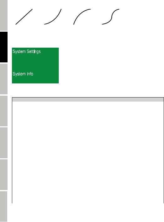
ENGLISH
FRANCAIS DEUTSCH
ESPAÑOL
POLSKI
ITALIANO
DMX
Dimmerkurven |
|
|
|
|
|
|
|
|
|
|
|
|
|
|
|
|
|
|
|||||
|
|
linear |
|
exponentiell |
|
logarithmisch |
|
|
S-Kurve |
||||||||||||||
|
|
|
|
|
Lichtintensität |
|
|
|
|
|
|
|
|
|
|
|
|
|
|
|
|
|
|
Lichtintensität |
|
|
|
|
|
|
|
|
|
|
Lichtintensität |
|
|
|
|
|
Lichtintensität |
|
|
|
|
|
|
|
|
|
|
|
|
|
|
|
|
|
|
|
|
|
|
|
|
|
|
||||
|
|
|
|
|
|
|
|
|
|
|
|
|
|
|
|||||||||
|
|
|
|
|
|
|
|
|
|
|
|
|
|
|
|||||||||
|
|
|
|
|
|
|
|
|
|
|
|
|
|
|
|||||||||
|
|
|
|
|
|
|
|
|
|
|
|
|
|
|
|||||||||
|
|
|
|
|
|
|
|
|
|
|
|
|
|
|
|
|
|
|
|
||||
|
DMX-Wert |
|
DMX-Wert |
|
DMX-Wert |
|
DMX-Wert |
||||||||||||||||
GERÄTEINFORMATIONEN (System Info)
Durch Drücken auf MODE gelangen Sie in das Auswahlmenü. Mit Hilfe der Bedienfelder und
und wählen Sie nun den Menü-Punkt „System Info“ aus (dunkel hinterlegt) und bestätigen mit ENTER.
Daraufhin gelangen Sie in das Untermenü zum Anzeigen der Geräteinformationen (Auswählen mit und
und , Information anzeigen lassen mit ENTER):
System Info
|
|
|
1U: |
Vx.xx |
|
Firmware |
= |
Anzeige der Geräte-Firmware |
2U: |
Vx.xx |
|
|
|
|
3U: |
Vx.xx |
|
Tempera- |
|
|
LED Temp |
xxx°C/F |
|
= |
Temperaturanzeige |
|
Celsius |
||
ture |
Temp Unit |
||||
|
|
Fahrenheit |
|||
|
|
|
|
||
Fan |
= |
Drehzahlanzeige |
Fan1: |
xxxxRPM |
|
Fan2: |
xxxxRPM |
||||
|
|
|
|||
|
|
|
Total: |
Anzeige der Gesamtbetriebszeit in Stunden und Minuten |
|
Time Info |
= |
Betriebszeitanzeige |
Current: |
Anzeige der aktuellen Betriebszeit in Stunden und Minuten |
|
|
|
|
Last: |
Anzeige der vorherigen Betriebszeit in Stunden und Minuten |
|
|
|
|
PAN |
Lösung: Reset Pan&Tilt |
|
|
|
|
TILT |
Lösung: Reset Pan&Tilt |
|
|
|
|
Gobowheel 1 |
Lösung: Reset Head. Evtl. korrekten Sitz und Position |
|
|
|
|
überprüfen |
||
|
|
|
|
||
|
|
"Funktionsfehleranzeige |
Gobowheel 1 Rot |
Lösung: Reset Head. Evtl. korrekten Sitz und Position |
|
|
|
überprüfen |
|||
|
|
Falls sich ein Funktionsfehler |
|
||
|
|
Gobowheel 2 |
Lösung: Reset Head |
||
|
|
durch einen Reset oder |
|||
Error Info |
= |
Neustart nicht beheben lässt, |
Colorwheel |
Lösung: Reset Head |
|
|
|
muss die defekte Einheit von |
Focus |
Lösung: Reset Head |
|
|
|
einem autorisierten Service- |
Zoom |
Lösung: Reset Head |
|
|
|
zentrum repariert werden." |
|||
|
|
Prism Rot |
Lösung: Reset Head |
||
|
|
|
|||
|
|
|
Fan 1 |
Lösung: Neustart |
|
|
|
|
Fan 2 |
Lösung: Neustart |
|
|
|
|
Temperature |
Lösung: Abkülen lassen, evtl. Neustart. Maximale Umge- |
|
|
|
|
bungstemperatur überprüfen (40°C) |
||
|
|
|
|
26
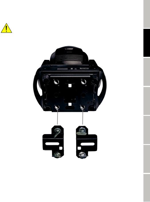
AUFSTELLUNG UND MONTAGE
Dank der integrierten Gummifüße kann der Scheinwerfer an einer geeigneten Stelle auf eine ebene Fläche gestellt werden. Die Montage an einer Traverse erfolgt mit Hilfe zweier Omega-Bügel, die an der Unterseite der Gerätebasis befestigt werden (A). Zwei Omega-Bügel sind im Lieferumfang enthalten, geeignete Traversenklemmen sind optional erhältlich. Sorgen Sie für feste Verbindungen und sichern Sie den Scheinwerfer mit einem geeigneten Sicherungsseil an einer der dafür vorgesehenen Stellen (B).
Wichtige Sicherheitshinweise: Überkopfmontage erfordert umfassende Erfahrung, einschließlich der Berechnung der Grenzwerte für die Arbeitslast, des verwendeten Installationsmaterials und der regelmäßigen Sicherheitsüberprüfung aller Installationsmaterialien und Scheinwerfer. Wenn Sie diese Qualifikationen nicht haben, versuchen Sie nicht, eine Installation selbst durchzuführen, sondern nutzen Sie die Hilfe von professionellen Unternehmen.
B
B
ENGLISH
FRANCAIS DEUTSCH
ESPAÑOL
POLSKI
A A
ITALIANO
DMX
27
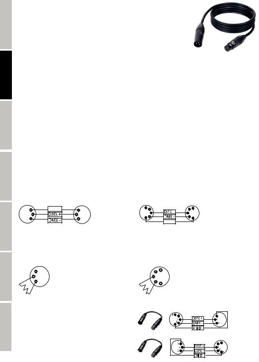
ENGLISH
FRANCAIS DEUTSCH
ESPAÑOL
POLSKI
ITALIANO
DMX
DMX TECHNIK
DMX-512
DMX (Digital Multiplex) ist die Bezeichnung für ein universelles Übertragungsprotokoll für die Kommunikation zwischen entsprechenden Geräten und Controllern. Ein DMX-Controller sendet DMX-Daten an das/die angeschlossene(n) DMX-Gerät(e). Die DMX-Datenübertragung
erfolgt stets als serieller Datenstrom, der über die an jedem DMX-fähigen Gerät vorhandenen DMX INund DMX OUT-Anschlüsse (XLR-Steckverbinder) von einem angeschlossenen
Gerät an das nächste weitergeleitet wird, wobei die maximale Anzahl der Geräte 32 nicht überschreiten darf. Das letzte Gerät der Kette ist mit einem Abschlussstecker (Terminator) zu bestücken.
DMX-VERBINDUNG:
DMX ist die gemeinsame "Sprache", über die sich die unterschiedlichsten Gerätetypen und Modelle verschiedener Hersteller miteinander verkoppeln und über einen zentralen Controller steuern lassen, sofern sämtliche Geräte und der Controller DMXkompatibel sind. Für eine optimale Datenübertragung ist es erforderlich, die Verbindungskabel zwischen den einzelnen Geräten so kurz wie möglich zu halten. Die Reihenfolge, in der die Geräte in das DMX-Netzwerk eingebunden sind, hat keinen Einfluss auf die Adressierung. So kann sich das Gerät mit der DMX-Adresse 1 an einer beliebigen Position in der (seriellen) DMX-Kette befinden, am Anfang, am Ende oder irgendwo in der Mitte. Wird einem Gerät die DMX-Adresse 1 zugewiesen, "weiß" der Controller, dass er alle der Adresse 1 zugeordneten Daten an dieses Gerät senden soll, ungeachtet seiner Position im DMX-Verbund.
SERIELLE VERKOPPLUNG MEHRERER SCHEINWERFER
1.Verbinden Sie den männlichen XLR-Stecker (3-Pol oder 5-Pol) des DMX-Kabels mit dem DMX-Ausgang (weibliche XLR-Buchse) des ersten DMX-Geräts (z.B. DMX-Controller).
2.Verbinden Sie den weibliche XLR-Stecker des an den ersten Scheinwerfer angeschlossenen DMX-Kabels mit dem DMX-Eingang (männliche XLR-Buchse) des nächsten DMX-Geräts. Verbinden Sie den DMX-Ausgang dieses Geräts in der gleichen Weise mit dem DMX-Eingang des nächsten Geräts und so weiter. Bitte beachten Sie, dass DMX-Geräte grundsätzlich seriell verschaltet werden und die Verbindungen nicht ohne aktiven Splitter geteilt werden können. Die maximale Anzahl der DMX-Geräte einer DMX-Kette darf 32 nicht überschreiten.
Eine umfangreiche Auswahl geeigneter DMX-Kabel finden Sie in den Adam Hall Produktlinien 3 STAR, 4 STAR und 5 STAR.
DMX-KABEL:
Beachten Sie bei der Anfertigung eigener Kabel unbedingt die Abbildungen auf dieser Seite. Verbinden Sie auf keinen Fall die Abschirmung des Kabels mit dem Massekontakt des Steckers, und achten Sie darauf, dass die Abschirmung nicht mit dem XLR-Steckergehäuse in Kontakt kommt. Hat die Abschirmung Massekontakt, kann dies zu Systemfehlern führen.
Steckerbelegung: |
|
|
|
|
|
|
DMX-Kabel mit 3-Pol XLR-Steckern: |
DMX-Kabel mit 5-Pol XLR-Steckern (Pin 4 und 5 sind nicht belegt.): |
|||||
1 |
Shield |
1 |
5 |
4 |
4 |
5 |
|
3 |
3 |
|
3 |
3 |
|
|
1 |
2 |
2 |
|
||
2 |
|
2 |
1 |
|||
|
|
|
|
|
Shield |
|
DMX-ABSCHLUSSSTECKER (TERMINATOR):
Um Systemfehler zu vermeiden, ist das letzte Gerät einer DMX-Kette mit einem Abschlusswiderstand zu bestücken (120 Ohm, 1/4 Watt). 3-Pol XLR-Stecker mit Abschlusswiderstand: K3DMXT3
5-Pol XLR-Stecker mit Abschlusswiderstand: K3DMXT5
Steckerbelegung: |
|
|
|
3-Pol XLR-Stecker: |
5-Pol XLR-Stecker: |
||
|
1 |
4 |
5 |
3 |
|
|
|
2 |
32 |
1 |
|
|
|
|
|
DMX-ADAPTER:
Die Kombination von DMX-Geräten mit 3-Pol Anschlüssen und DMX-Geräten mit 5-Pol Anschlüssen in einer DMX-Kette ist mit Hilfe von Adaptern ebenso möglich.
Steckerbelegung
DMX-Adapter 5-Pol XLR male auf 3-Pol XLR female: K3DGF0020
Pin 4 und 5 sind nicht belegt.
Steckerbelegung
DMX-Adapter 3-Pol XLR male auf 5-Pol XLR female: K3DHM0020
Pin 4 und 5 sind nicht belegt.
28
TECHNISCHE DATEN
Artikelnummer: |
CLASZ300 |
Produktart: |
LED Moving Light |
Typ: |
Moving Head |
Farbspektrum LED: |
Kaltweiß 19500K |
LED Anzahl: |
1 |
LED Typ: |
200W |
Anzahl Farben: |
8 + offen und stufenlosen Farbradpositierung |
Anzahl Gobos: |
6 fix + 6 rotierbar & indizierbar + offen |
Wiederholrate: |
800 Hz; 1200 Hz; 2000 Hz; 3600 Hz; 12 kHz; 25 kHz |
Abstrahlwinkel: |
10° - 20° |
DMX-Eingang: |
3-Pol XLR männlich |
|
5-Pol XLR männlich |
DMX-Ausgang: |
3-Pol XLR weiblich |
|
5-Pol XLR weiblich |
DMX-Modus: |
17-Kanal, 20-Kanal |
DMX Funktionen: |
Pan/Tilt, Pan/Tilt fein, Dimmer, Stroboskop, Farbrad, Goborad fix, Goborad rotierend, Gobo Rotation, |
|
Gobo Shake, 2 x Prisma, Fokus, Frost, Zoom, Bewegungsmakro, Auto Programme, Geräteeinstel- |
|
lungen |
Stand-Alone Funktionen: |
Auto Programm, Benutzer Makros, Master/Slave-Betrieb |
Steuerung: |
DMX512, RDM enabled |
Pan Winkel: |
540° / 630° |
Tilt Winkel: |
270° |
Bedienelemente: |
Mode, Enter, 4x Pfeiltasten |
Anzeigeelemente: |
Beleuchtetes Farb-LC-Display, Batteriespeisung für netzunabhängige Systemeinstellungen (autom- |
|
atisch wiederaufladender Akku) |
Betriebsspannung: |
100 - 240 V AC / 50 - 60 Hz |
Leistungsaufnahme: |
320 W |
Beleuchtungsstärke (@ 1m): |
162000 lx |
Lichtstrom: |
7500 lm |
Stromversorgungsanschluss: |
Neutrik powerCON Einund Ausgang (Max. Ausgangsstrom 9A) |
Sicherung: |
T4AL 250V (5 x 20mm) |
Umgebungstemperatur (in Betrieb): |
0°C - 40°C |
Relative Luftfeuchtigkeit: |
< 85%, nicht kondensierend |
Gehäusematerial: |
Metall, ABS |
Gehäusefarbe: |
Schwarz |
Gehäusekühlung: |
Temperaturgesteuerte Lüfter |
Abmessungen (B x H x T, ohne |
282 x 469 x 186mm |
Montagebügel): |
|
Gewicht: |
11,3 kg |
Weitere Eigenschaften: |
1m Netzkabel mit Neutrik powerCON-Stecker |
|
und 2 x Omega-Montagebügel im Lieferumfang, Gobos Goborad 1 austauschbar |
ENGLISH
FRANCAIS DEUTSCH
ESPAÑOL
POLSKI
ITALIANO
DMX
29
 Loading...