

Page 1
azur 540A/640A
Integrated amplifier / HIFI-Verstärker / Amplificateur intégré / Amplificador integrado / Amplificatore
integrato / Geïntegreerde versterker / Integreret forstærker / Встроенный усилитель
User’s manual / Bedienungsanleitung / Mode d'emploi / Manual del usuario / Manuale per l'utente /
Gebruikershandleiding / Brugermanual / Руководство для пользователя
Page 2

2
Thank yyou ffor ppurchasing tthis CCambridge AAudio aazur sseries aamplifier. IIt
is tthe rresult oof oour mmost eext
ensive eever rresearch aand ddevelopment
program iin oover tthree ddecades oof pproducing hhigh qquality aaudio pproducts.
We hhope tthat yyou wwill aappreciate tthe rresults aand eenjoy mmany yyears oof
listening ppleasure.
About tthis aamplifier
The design of any purist audio amplifier is mainly centred on two main
areas, the Power Supply and the driver stage's ability to drive the output
stage effectively. We at Cambridge Audio have researched the best
possible ways to achieve the highest performance in these areas, at a
sensible price. The Azur 540A/640A topology uses the same tried and
tested output devices that Cambridge Audio have used in previous
award winning amplifier models, but many hours of research have gone
into the study and development of the preceding stages. This driver
circuitry is essentially a matched differential input pair, loaded by a
current mirror and driven from a transient compensated current source
driving a high beta cascoded voltage gain stage. The thermally
compensated output stage is setup to inherently give optimum Class AB
conditions (for greatly reduced cross over distortion caused by dynamic
heating of the output dies). In addition the topology includes a further
improvement to the driver stage consisting of a pure class-A follower to
isolate the voltage amplifier transistors from the difficult loading of the
output transistors. This increased current drive to the output stage
combined with a novel transient feed forward circuit doubles the slew
rate to 40V/uS.
Due to critically refined circuit board layouts, careful component
placement and short signal paths the stability of these amplifiers is
extremely high which allows the compensation components to be
reduced in size. This has the effect of reducing distortion, increasing
dynamics and allowing the bandwidth to be opened up to a massive
80kHz, ideal for the new 'better than CD' high bandwidth sources such
as DVD-Audio and Super Audio CD.
The performance of any amplifier is limited by the dynamic abilities of its
power supply, and f or this reason Cambridge Azur amplifiers incorporat e
many features, including a low flux toroidal transformer, paralleling of
the reservoir capacitors and careful use of bypass capacitors, to allow
the instantaneous clean delivery of charge whenever it is needed. This
ensures an open and natural sound being reproduced and ensures a
positive response to any dynamics or sudden transients in the signal
being reproduced.
Particular attention has also been paid to the quality of the passive
components which have been carefully chosen for their sonic benefits.
The Azur 640A in addition uses high grade Polypropylene signal bypass
capacitors to improve signal flow and dynamics.
The Cambridge Audio Azur 540A and 640A amplifiers also incorporate
tone controls, which may be switched out of circuit in 'direct' mode for
the shortest and therefore purest signal path. Other features include
24k gold plated phono sockets, dual tape loops, pre amp output, a
headphone socket and a secondary set of high level loudspeaker
terminals.
An important feature which has been included as standard on both the
540A and 640A is the new innovative Cambridge Audio designed CAP5
protection system. This consists of a microprocessor which constantly
monitors the amplifier providing comprehensive protection against a
variety of possible faults. This has been achieved without adding any
active circuitry into the signal path to degrade the sound or the dynamic
abilities of the amplifier.
INTRODUCTION
Page 3

540A/640A Integrated amplifier
3
Cambridge Audio has built up an extensive knowledge base due to
meticulous listening and tweaking. This attention to detail results in
amplifiers that are totally convincing in the reproduction of both tonal
colour and dynamic contrast, deliver a vibrant and fluid performance
with music of all types and are extremely musically involving.
To get the absolute best from this equipment we would encourage you
to use only high quality source components. Of course we particularly
recommend tuners and digital equipment from the Cambridge Audio
range, all of which have been designed to the same exacting standards
as our amplifiers. Many types of loudspeakers were used in the
development of these amplifiers to ensure maximum compatibility with
a wide variety of designs.
Interconnects and speaker cables are also something that shouldn't be
overlooked. Please do not compromise your system's performance by
using poor quality cables to connect source components to your
amplifier or the amplifiers output to your loudspeakers. A system is only
as good as its weakest link. For this reason we do not include cheap
"freebie" cables with any of our products. Your dealer can supply good
quality Cambridge Audio interconnects and Mordaunt Short/Gale
loudspeaker cables that will make a noticeable improvement to the
sound quality of your system.
Now wwe iinvite yyou tto ssit bback, rrelax aand eenjoy!
Matthew Bramble
Technical Director
Introduction.................................................................................................2
Safety precautions......................................................................................4
Installation...................................................................................................5
Rear panel connections .............................................................................6
Connecting.................................................................................................. 8
Operating instructions..............................................................................10
CAP5 - Five way protection system...........................................................12
Troubleshooting.........................................................................................14
Specifications............................................................................................14
Limited warranty.......................................................................................15
CONTENTS
Page 4
4
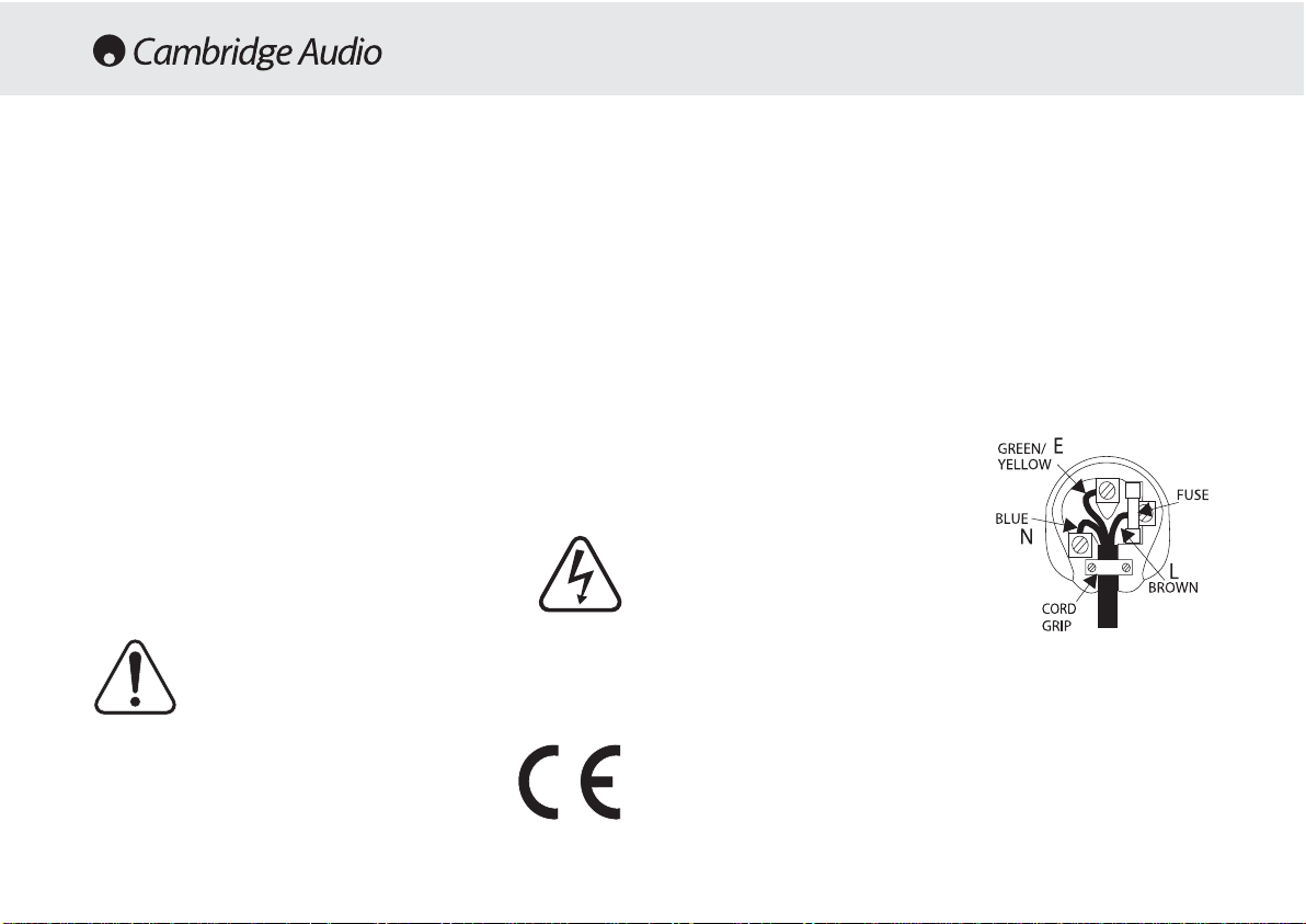
Plug ffitting iinstructions ((UK only)
The cord supplied with this appliance is factory fitted with a 13A mains plug fitted
with a 3A fuse inside. If it is necessary to change the fuse, it is important that a 3A
one is used. If the plug needs to be changed because it is not suitable for your
socket, or becomes damaged, it should be cut off and an appropriate plug fitted
following the wiring instructions below. The plug must then be disposed of safely,
as insertion into a 13A socket is likely to cause an electrical hazard. Should it be
necessary to fit a 3-pin BS mains plug to the power cord the wires should be fitted
as shown in this diagram. The colours of the wires in the mains lead of this
appliance may not correspond with the coloured markings identifying the
terminals in your plug. Connect them as follows:-
The wire which is coloured BLUE must be
connected to the terminal which is marked
with the letter 'N' or coloured BLACK.
The wire which is coloured BROWN must be
connected to the terminal which is marked
with the letter 'L' or coloured RED
The wire which is coloured GREEN/YELLOW
must be connected to the terminal which is
marked with the letter 'E' or coloured
GREEN.
If your model does not have an earth wire,
then disregard this instruction.
If a 13 Amp (BS 1363) plug is used, a 3 Amp fuse must be fitted, or if any other
type of plug is used a 3 Amp or 5 Amp fuse must be fitted, either in the plug or
adaptor, or on the distribution board.
Checking tthe ppower ssupply rrating
For your own safety please read the following instructions carefully before
attempting to connect this unit to the mains.
Check that the rear of your unit indicates the correct supply voltage. If your mains
supply voltage is different, consult your dealer.
This unit is designed to operate only on the supply voltage and type that is
indicated on the rear panel of the unit. Connecting to other power sources may
damage the unit.
This equipment must be switched to Standby mode when not in use, unplugged if
not used for long periods of time, and must not be used unless correctly earthed.
To reduce the risk of electric shock, do not remov e the unit's co v er (or back). There
are no user serviceable parts inside. Refer servicing to qualified service personnel.
If the power cord is fitted with a moulded mains plug the unit must not be used if
the plastic fuse carrier is not in place. Should you lose the fuse carrier the correct
part must be reordered from your Cambridge Audio dealer.
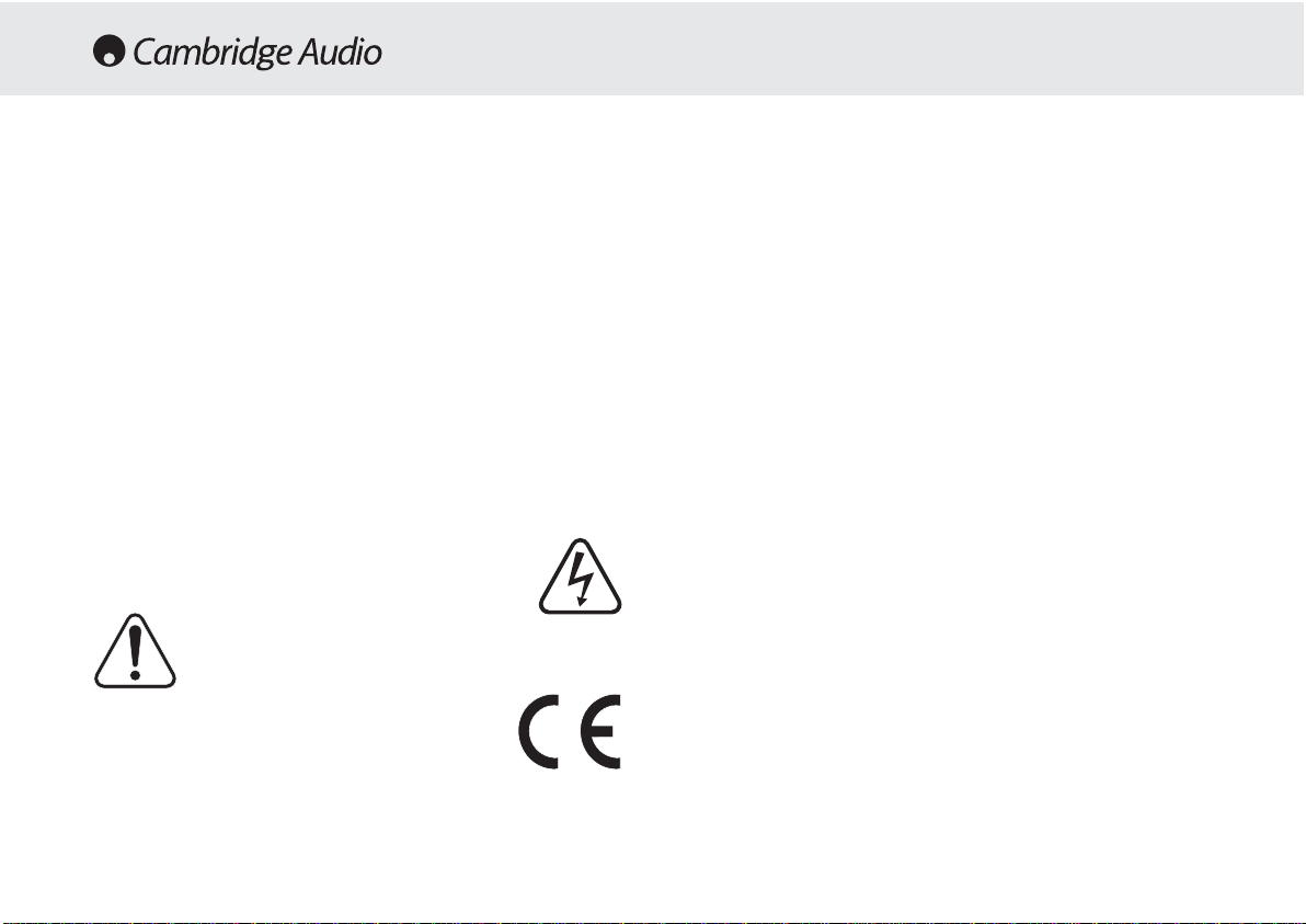
The lightning flash with the arrowhead symbol within an equilateral
triangle is intended to alert the user to the presence of uninsulated
'dangerous voltage' within the product's enclosure that may be of
sufficient magnitude to constitute a risk of electric shock to
persons.
The exclamation point within an equilateral triangle is intended to
alert the user to the presence of important operating and
maintenance instructions in the service literature relevant to this
appliance.
This product complies with European Low Voltage (73/23/EEC)
and Electromagnetic Compatibility (89/336/EEC) Directives
when used and installed according to this instruction manual. For
continued compliance only Cambridge Audio accessories should
be used with this product and servicing must be referred to
qualified service personnel.
SAFETY PRECAUTIONS
Page 5

540A/640A Integrated amplifier
5
Please take a moment to read these notes before installing your
amplifier, they will enable you to get the best performance and prolong
the life of the product.
The unit requires ventilation above and below. Do not situate it on a rug
or other soft surface and do not obstruct the air inlet and outlet grilles
on the underside and top cover. Do not place in an enclosed area such
as a bookcase or in a cabinet.
This unit must not be exposed to dripping or splashing water or other
liquids. No objects filled with liquid, such as vases, shall be placed on
the unit. In the event, switch off immediately, disconnect fr om the mains
supply and contact your dealer for advice.
Ensure that small objects do not fall through any ventilation grille. If this
happens, switch off immediately, disconnect from the mains supply and
contact your dealer for advice.
Do not route the power cable so that it can be walked upon or damaged
by other items near it.
Electronic audio components have a running in period of around a week
(if used several hours per day). This will allow the new components to
settle down, the sonic properties will improve over this time.
It is recommended that when bi-amping, the same type power amplifiers
are used.
This amplifier has been designed to be left in Standby mode when not
in use, this will increase the life of the amplifier (this is true with all
electronic equipment). If you do not intend to use this unit for a long
period of time, unplug it from the mains socket.
To clean the unit, wipe its case with a moist, lint-free cloth. Do not use
any cleaning fluids containing alcohol, ammonia or abrasives. Do not
spray an aerosol at or near the amplifier.
These units are not user serviceable, never attempt to repair,
disassemble or reconstruct the unit if there seems to be a problem. A
serious electric shock could result if this precautionary measure is
ignored. In the event of a problem or failure, please contact your dealer.
This unit should be installed on a sturdy, level surface. Due to stray
magnetic fields turntables should not be located nearby due to
interference.
INSTALLATION
Page 6
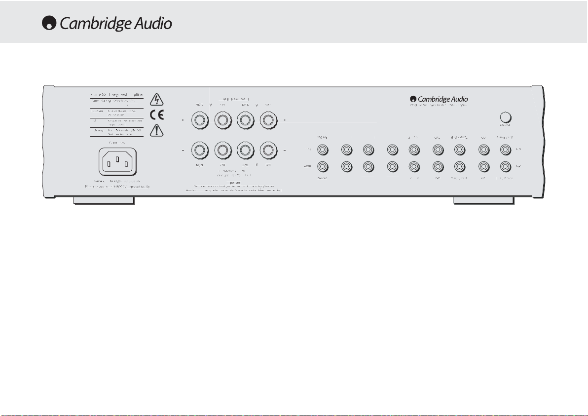
6
AC power ssocket
Once you have completed all connections to the amplifier, plug the AC
Power Cable into an appropriate mains socket. The amplifier is now
ready for use.
Loudspeaker cconnections
The 540A and 640A have two sets of Loudspeaker terminals on the rear
panel, speakers A and B. Speakers A are the main speaker terminals,
speakers B are the secondary switchable speaker terminals. Connect
the wires from your left channel loudspeaker to the LEFT + & - terminals,
and likewise the wires from the right channel loudspeaker to the RIGHT
+ & - terminals. In each case the red terminal is the positive output, and
the black terminal is the negative input. Care should be taken to ensure
no stray strands of wire are shorting speaker outputs together. Please
Note: TThis aamplifier hhas bbeen ddesigned ffor uuse wwith lloudspeakers tthat
have aa nnominal iimpedance oof bbe
tween 44 aand 88 oohms.
Please eensure tthat tthe sspeaker tterminals hhave bbeen ttightened
adequately tto pprovide a
a ggood eelectrical cconnection. IIt iis ppossible ffor tthe
sound qquality tto bbe aaffected iif tthe sscrew tterminals aare lloose.
Pre aamp oouts
Connect these sockets to the inputs on an external Power Amplifier(s).
Tape mmon
These sockets can be connected to a tape deck or to the analog sock ets
on a MiniDisc or CD recorder. Connect an interconnect cable from the
recorder's Line Out sockets to the amplifier's Tape Monitor sockets. This
T
2
T
R
2
M
:
P
Pre-Out
I
Impedance 4 - 8 ohms
L
Loudspeaker Terminals
Important
P
Please ensure that loudspeaker terminals are fully tightened
Veuillez s'assurer que les bornes de l'enceinte sont entierement serreesVeuillez s'assurer que les bornes de l'enceinte sont entierement serrees
I
Impedance 4 - 8 ohms
R
Right
L
Left
R
Right
L
Left
Left
R
Right
L
Left
R
Right
B
B
A
A
AV / MD
T
Tuner / DAB
o
Aux / Phono
P
Pre-Out
AV / MD
DVDDVD
Tuner / DAB
C
CD
A
Aux / Phono
R
Right
L
Left
RightRight
L
Left
d
Ground
w
k
www.cambridge-audio.co.uk
M
Manufactured in an
I
2
ISO9002
approved facility
P
C
Power AC
D
Designed and Engineered in London, England
R
k
Risk of electric shock
D
n
Do not open
C
Caution
Risque de choc electrique
Ne pas ouvrir
Vorm offnen des geratesVorm offnen des gerates
N
Netzstecker ziehen
Achtung
a
r
azur 640A Integrated Amplifier
Power Rating:
230V AC 50Hz
230V AC 50Hz
REAR PANEL CONNECTIONS
zur 640A Integrated Amplifie
Power Rating:
ax Power Consumption
isk of electric shoc
aution
o not ope
Avis
Risque de choc electrique
Ne pas ouvrir
Achtung
etzstecker ziehen
ower A
ww.cambridge-audio.co.u
anufactured in an
SO900
615W
approved facility
ight
ight
A
oudspeaker Terminals
lease ensure that loudspeaker terminals are fully tightened
eft
eft
mpedance 4 - 8 ohms
Important
mpedance 4 - 8 ohms
ight
ight
Left
eft
esigned and Engineered in London, England
Groun
re-Out
ape In
ec Out 1
eft
ape InRec Out 1Rec Out
re-Out
AV / MD
Rec Out
AV / MD
uner / DAB
Tuner / DAB
D
CDCDAux / Phon
ux / Phono
eft
ight
Page 7

540A/640A Integrated amplifier
7
monitor doubles up as the standard tape/recording medium input.
Note: WWhen cconnecting aa ssource ccomponent tthat hhas bboth aan iinput aand
output ii.e. aa ttape rrecorder, tthe o
output oof wwhich sshould aalways bbe
connected tto tthe TTape MMon iinput. TThis wwill eeliminate hhowlround iif tthe
wrong iinput cchannel iis sselected.
Tape oout
These sockets can be connected to a tape deck or to the analog sock ets
on a MiniDisc or CD recorder. Connect an interconnect cable from the
Tape Out sockets of this amplifier to the recorder's Line In. Please note
that this unit has two tape loops which have identical outputs.
CD/Tuner/DVD/AV/MD iinput ssockets
These inputs are suitable for any 'line level' source equipment such as
CD players, DAB or FM/AM tuners etc.
Aux/Phono iinput ssockets
Connect any 'line level' source equipment t o these sockets i.e. CD player
or DAB tuner. Alternatively this particular input can be converted to a
dedicated turntable if desired although to do this a Cambridge Audio
PM01 Phono Module must be fitted. Please contact your Cambridge
Audio dealer who can supply and install a phono stage to your amplifier.
These iinputs aare ffor aanalog aaudio ssignals oonly. TThey sshould nnot bbe
connected tto tthe ddigital ooutput oo
f aa CCD pplayer oor aany oother ddigital ddevice.
Ground cconnection
If you are connecting a turntable to your amplifier then its ground wire
should be attached to this point
Page 8
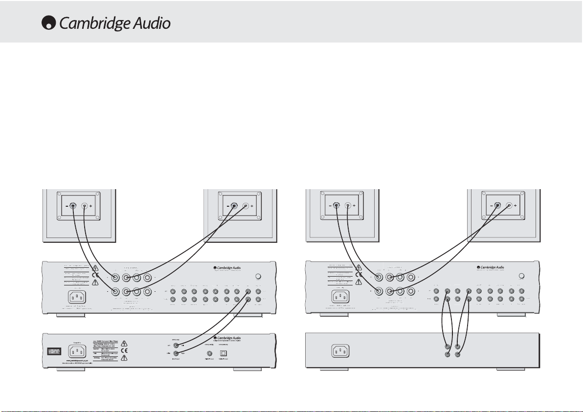
8
When designing our amplifiers we have tried to include features that
allow you to connect your system in various ways. The inclusion of
features such as PRE-OUT and SPEAKER B connections mean that you
can configure your system depending on your requirements. The
following diagrams are designed to make connection easy.
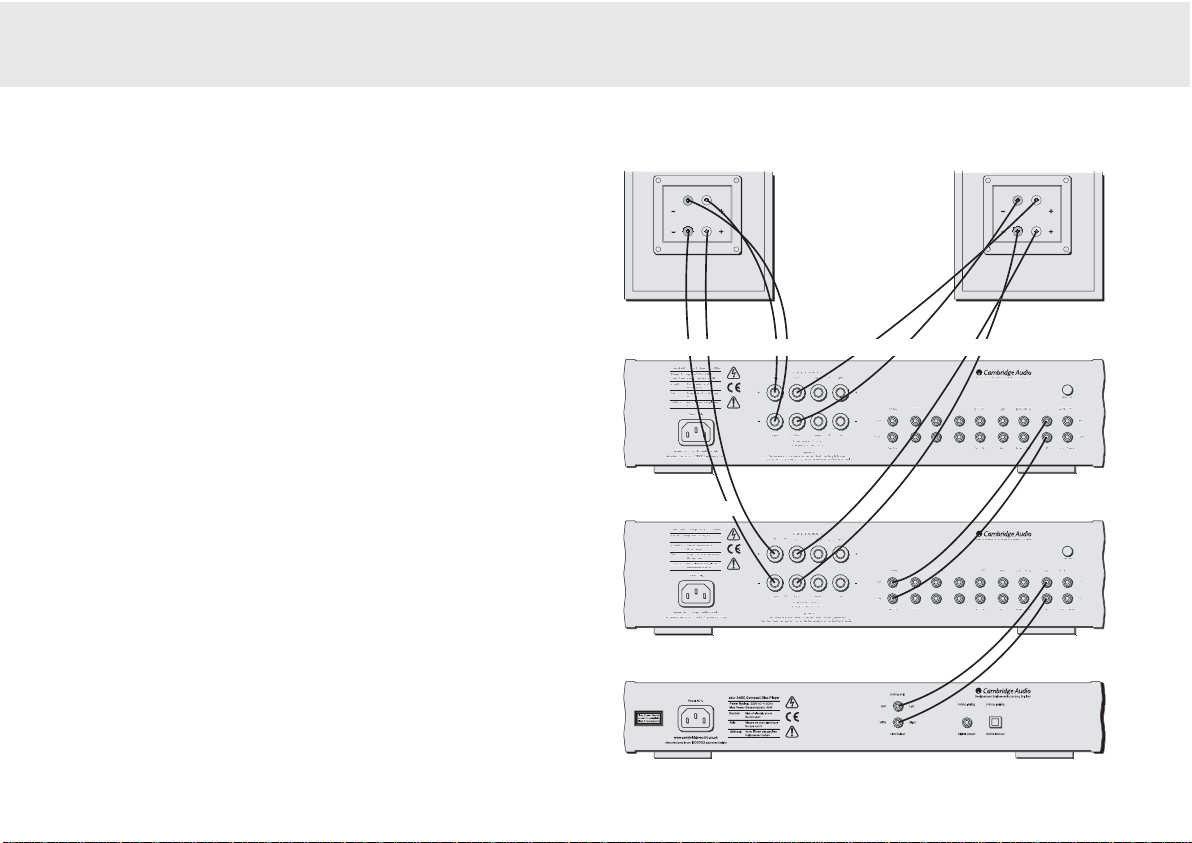
Basic cconnection
The following diagram shows the basic connection of your amplifier to a
CD player and a pair of loudspeakers.
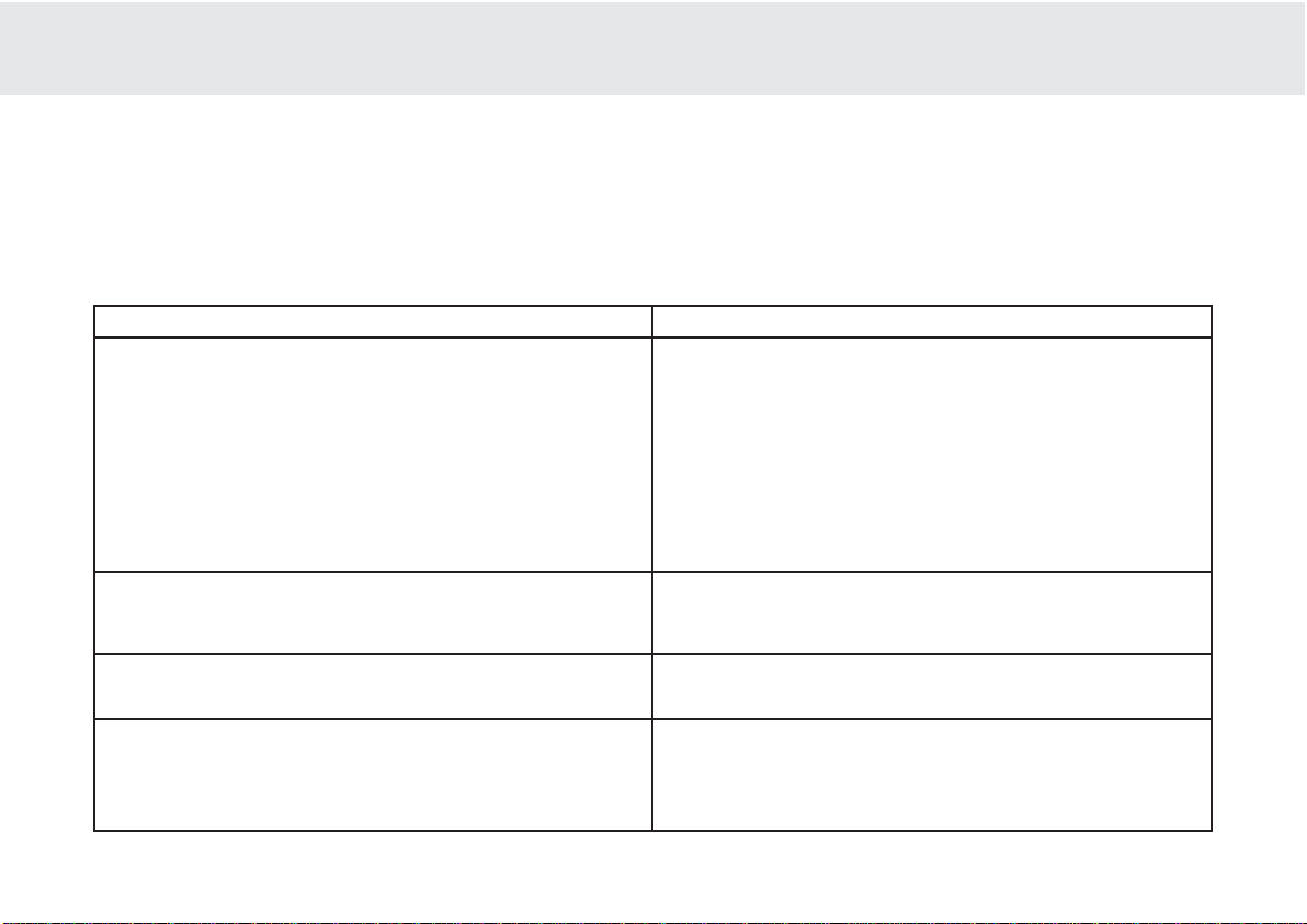
Tape cconnection
The following diagram shows how to connect the amplifier to a tape
recorder or other source with a record and monitor connection.
Please note that either of the tape loop outputs can be used (as they are
both the same).
CONNECTING
M
:
t
Pre-Out
Impedance 4 - 8 ohms
Loudspeaker Terminals
Important
P
Please ensure that loudspeaker terminals are fully tightened
Veuillez s'assurer que les bornes de l'enceinte sont entierement serrees
Veuillez s'assurer que les bornes de l'enceinte sont entierement serrees
Impedance 4 - 8 ohms
R
Right
Left
R
Right
Left
Left
L
Left
Righ
Right
L
Left
Right
B
B
A
R
1
Rec Out 1
R
2
Rec Out 2
T
n
Tape In
AV / MD
Tuner / DAB
CD
A
o
Aux / Phono
P
Pre-Out
R
RecOut 1
R
2
RecOut 2
T
n
Tape In
AV / MD
AV / MD
DVD
DVD
Tuner / DAB
CDCD
Aux / Phono
R
Right
Left
Left
R
Right
L
Left
G
d
Ground
w
www.cambridge-audio.co.uk
M
Manufactured in an
2
ISO9002
y
approved facility
P
Power AC
D
d
Designed and Engineered in London, England
R
Risk of electric shock
D
n
Do not open
Caution
Caution
e
Risque de choc electrique
Ne p
Ne pas ouvrir
Avis
Vorm offnen des gerates
Vorm offnen des gerates
N
n
Netzstecker ziehen
Ach
g
Achtung
a
azur 640A Integrated Amplifier
Power Rating:
230V AC 50Hz
230V AC 50Hz
T
1
R
2
T
R
2
M
:
tPre-Out
Impedance 4 - 8 ohms
Loudspeaker Terminals
Important
P
Please ensure that loudspeaker terminals are fully tightened
Veuillez s'assurer que les bornes de l'enceinte sont entierement serrees
Veuillez s'assurer que les bornes de l'enceinte sont entierement serrees
Impedance 4 - 8 ohms
R
Right
Left
R
Right
Left
Left
L
Left
Righ
Right
L
Left
Right
B
B
A
A
AV / MD
Tuner / DAB
CD
A
o
Aux / Phono
P
Pre-Out
AV / MD
AV / MD
DVD
DVD
Tuner / DAB
CDCD
Aux / Phono
R
Right
Left
Left
R
Right
L
Left
G
d
Ground
w
www.cambridge-audio.co.uk
M
Manufactured in an
2
ISO9002
y
approved facility
P
Power AC
D
d
Designed and Engineered in London, England
R
Risk of electric shock
D
n
Do not open
Caution
Caution
e
Risque de choc electrique
Ne p
Ne pas ouvrir
Avis
Vorm offnen des gerates
Vorm offnen des gerates
N
n
Netzstecker ziehen
Ach
g
Achtung
a
azur 640A Integrated Amplifier
Power Rating:
230V AC 50Hz
230V AC 50Hz
Rec InRec Out
Tape // MMD Player
zur 640A Integrated Amplifier
Power Rating:
ax Power Consumption
isk of electric shock
o not ope
Risque de choc electriqu
as ouvrir
tun
etzstecker ziehe
ower AC
ww.cambridge-audio.co.uk
anufactured in an
ISO900
615W
approved facilit
Impedance 4 - 8 ohms
eft
Right
A
t
ight
Left
ight
Impedance 4 - 8 ohms
Loudspeaker Terminals
Important
lease ensure that loudspeaker terminals are fully tightened
eft
re-Out
eft
ight
ec Out
Pre-Ou
esigned and Engineered in London, Englan
ec Out 1
ape I
ec Out
ec Out
ape I
AV / MD
roun
Tuner / DAB
Aux / Phono
Tuner / DAB
ight
CD
ux / Phon
zur 640A Integrated Amplifier
Power Rating:
ax Power Consumption
615W
isk of electric shock
o not ope
Risque de choc electriqu
as ouvrir
tun
etzstecker ziehe
ower AC
ww.cambridge-audio.co.uk
anufactured in an
ISO900
approved facilit
Impedance 4 - 8 ohms
eft
Right
t
ight
Left
ight
Impedance 4 - 8 ohms
Loudspeaker Terminals
Important
lease ensure that loudspeaker terminals are fully tightened
eft
re-Out
eft
ight
ape In
Pre-Ou
ape In 1
ec Out 1
ec Out 1Rec Out
esigned and Engineered in London, Englan
Rec Out
AV / MD
roun
Tuner / DAB
Aux / Phono
Tuner / DAB
ight
CD
ux / Phon
Page 9
540A/640A Integrated amplifier
9
Bi-aamping
The azur amplifiers are equipped with PRE-OUT sockets. If your
loudspeakers have two sets of terminals then it is possible to bi-amp
your system using a further power amplifier. Bi-amping uses two
amplifiers to drive the bass and treble units in the loudspeakers
independently, resulting in even greater clarity coupled with improved
control and dynamics. An example of a bi-amp setup is illustrated in the
diagram adjacent.
Please note that if using a second azur amplifier as the slave amplifier,
any line input can be used to connect from the master’s Pre-Out.
Using SSpeaker BB connections
The Speaker B connections on the back of the amplifier allow a second
set of speakers to be used, which could be for another room.
2
R
1
R
2
M
n
:
W
P
Pre-Out
I
Impedance 4 - 8 ohms
L
Loudspeaker Terminals
Important
P
Please ensure that loudspeaker terminals are fully tightened
Veuillez s'assurer que les bornes de l'enceinte sont entierement serrees
Veuillez s'assurer que les bornes de l'enceinte sont entierement serrees
I
s
Impedance 4 - 8 ohms
R
Right
L
Right
L
Left
Right
Right
Left
Right
Right
B
B
A
A
AV / MD
B
Tuner / DAB
CDCD
o
Aux / Phono
P
Pre-Out
AV / MD
AV / MD
DVD
DVD
Tuner / DAB
CDCD
o
Aux / Phono
t
Right
Left
R
Right
L
Left
d
Ground
w
www.cambridge-audio.co.uk
M
Manufactured in an
I
2
ISO9002
y
approved facility
P
C
Power AC
D
Designed and Engineered in London, England
R
D
Do not open
Caution
Caution
e
Risque de choc electrique
Ne p
Ne pas ouvrir
Avis
Avis
Vorm offnen des gerates
Vorm offnen des gerates
N
Netzstecker ziehen
g
Achtung
r
azur 640A Integrated Amplifier
Power Rating:
230V AC 50Hz
230V AC 50Hz
Rec Out 1
R
2
T
n
Rec Out 1
Rec Out 2
P
Pre-Out
Imp
Impedance 4 - 8 ohms
L
Loudspeaker Terminals
Important
P
Please ensure that loudspeaker terminals are fully tightened
Veuillez s'assurer que les bornes de l'enceinte sont entierement serrees
Veuillez s'assurer que les bornes de l'enceinte sont entierement serrees
Imp
s
Impedance 4 - 8 ohms
Righ
Right
L
Right
L
Left
B
t
Right
Left
Right
Right
B
B
A
AV / MD
B
Tuner / DAB
CDCD
o
Aux / Phono
P
Pre-Out
AV / MD
DVD
DVD
T
DAB
Tuner / DAB
CDCD
A
o
Aux / Phono
t
Right
R
Right
L
Left
d
Ground
w
www.cambridge-audio.co.uk
M
Manufactured in an
I
2
ISO9002
approved facility
P
C
D
Designed and Engineered in London, England
R
D
Do not open
C
n
Caution
e
Risque de choc electrique
Ne pas ouvrir
Avis
Avis
Vorm offnen des gerates
Vorm offnen des gerates
N
Netzstecker ziehen
g
Achtung
r
azur 640A Integrated Amplifier
Power Rating:
230V AC 50Hz
230V AC 50Hz
M
n
Max Power Consumption
:
:
W
615W
Master aamplifier
Slave aamplifier
- if using an integrated amplifier, volume must be set to full
CD player
Bass Bass
Treble Treble
azur 640A Integrated Amplifie
Power Rating:
ax Power Consumptio
615
isk of electric shock
autio
o not open
Risque de choc electriqu
Ne pas ouvrir
Achtun
etzstecker ziehen
ower A
ww.cambridge-audio.co.uk
anufactured in an
SO900
approved facility
azur 640A Integrated Amplifie
Power Rating:
ax Power Consumptio
615
isk of electric shock
o not open
Risque de choc electriqu
as ouvrir
Achtun
etzstecker ziehen
ower A
ww.cambridge-audio.co.uk
anufactured in an
SO900
approved facilit
edance 4 - 8 ohm
Left
A
A
eftRight
edance 4 - 8 ohms
oudspeaker Terminals
Important
Left
eftRight
mpedance 4 - 8 ohms
oudspeaker Terminals
Important
mpedance 4 - 8 ohm
eft
re-Out
eft
ight
Left
eft
Left
eft
ight
re-Out
re-Out
re-Out
Tape In
Tape InRec Out 1Rec Out
esigned and Engineered in London, England
ec Out
ec Out
ec Out
AV / MD
AV / MD
esigned and Engineered in London, England
AV / MD
ape I
Tape In
Righ
t
lease ensure that loudspeaker terminals are fully tightened
ight
lease ensure that loudspeaker terminals are fully tightened
Groun
uner /
ux / Phon
Left
Tuner / DA
Tuner / DA
Righ
Aux / Phon
Groun
Tuner / DAB
Aux / Phon
Left
Righ
Aux / Phon
Page 10
10
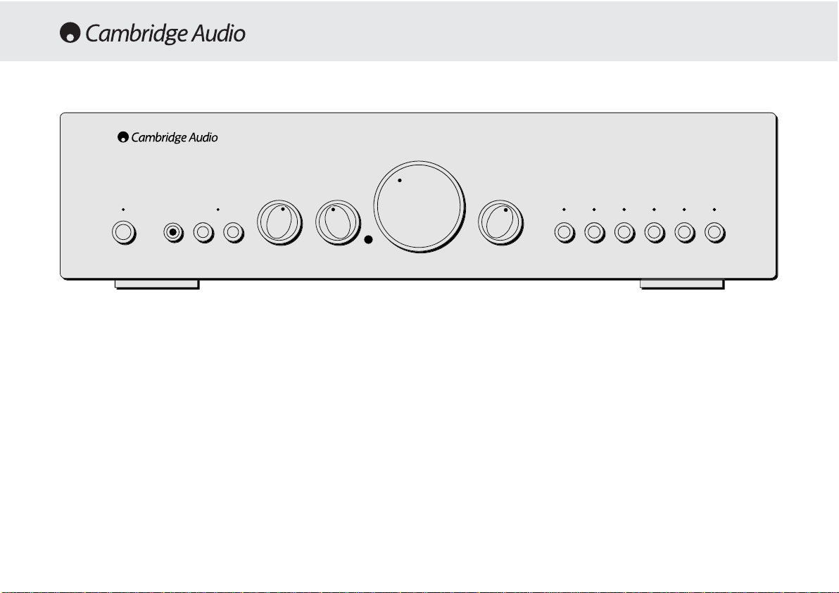
Standby/On
Switches the unit between Standby mode (indicated by dim power LED)
and On (indicated by bright power LED). Standby is a low power mode
where the power consumption is less than 10 Watts. The unit should be
left in standby when not in use.
Headphone ssocket
Allows for the connection of headphones with a ¼" Jack plug connector.
When the headphones are connected the loudspeaker relay is released
switching off the output to the loudspeakers (Speakers A and B).
Speaker BB oon/off
Enables/disables the secondary set of speaker terminals on the back
panel. This can be used for listening to an extra set of speakers in
another room.
Please note that care should be taken when selecting if two
loudspeakers are going to be used on each channel. If the combined
resistance measured on the speaker terminals is too low the amplifier
may not switch out of standby mode until a suitable load resistance is
detected. For more information please see section on CAP5 protection
system.
Note - WWhen uusing ttwo ppairs oof sspeakers eeach ppair sshould bbe rrated aat
least 66 oohms ((or hhigher). 44 oohm
sspeakers aare nnot rrecommended wwhen
using mmore tthan oone ppair.
Direct
This control gives the audio signal a more direct path to the power
amplifier stage of your amplifier, bypassing the tone control circuits for
the purest possible sound quality.
OPERATING INSTRUCTIONS
Volume
azur 640A
Integrated Amplifier
TrebleBass
Standby / On
Protection
Direct
Speaker BPhones
Balance
Aux / Phono
CD
DVD
Tape Mon
AV / MDTuner / DAB
Page 11

540A/640A Integrated amplifier
11
Bass aand ttreble ttone ccontrols
These controls allow subtle adjustments to the tonal balance of the
sound. In the central position these controls have no effect. These
controls only modify the sound through your loudspeakers and the PreOut sockets (where featured), they do not affect the signals sent thr ough
the Tape Out connections. With a well produced CD and a good system
the tone controls are unnecessary and can be switched out. If the
musical recording is of poor quality and/or the
loudspeakers/surroundings are lacking it may be necessary to adjust
the tone controls to compensate.
Volume
The Volume control increases/decreases the lev el of the sound fr om the
outputs of the amplifier. This control affects the le vel of the Loudspeak er
output, the pre amp output and the headphone output. It does not affect
the Tape Out Connections.
It is advisable to turn the Volume control fully anti-clockwise before
switching the amplifier on.
Balance
This control allows you to adjust the relative output levels of the left and
right channels. In the central position the output from each channel is
equal. This control only modifies the sound through your loudspeakers
and the Pre-Out sockets (where featured), it does not affect the signals
sent through the Tape Out connections.
Input sselection ppush bbuttons
Push the appropriate input selection button to select the source
component that you wish to listen to. The signal selected is also fed to
the Tape Out sockets so that it may be recorded. The input should not
be changed whilst recording, although the recorded signal can be
checked using the tape input Tape monitor.
Tape mmonitor sselection bbutton
This control lets you listen to the output signal from a tape recorder or
signal processor connected to the amplifier's Tape monitor sockets.
When Tape monitor is selected, the source component chosen by the
input selection push buttons continues to be routed to the Tape Out
sockets for recording or processing.
Remote ccontrol ooperation/features
This Amplifier is supplied with a system remote control that operates
both this amplifier and the Cambridge Azur CD players. The functions
relevant to the amplifier are as follows:
Power -
Switches the amplifier between Standby mode and On mode.
Mute -
Mutes the audio (indicated by the input LEDflashing).
Volume ++/-
- The volume buttons increase and decrease the Volume of
the amplifier output.
Input sselect -
The five input select buttons and the Tape monitor select
button are used to change the input source.
Page 12

12
If the Loudspeaker impedance is low the temperature of the amplifier
may rise faster as the amplifier is working harder. If the amplifier is
mounted in a cabinet or the ventilation slots are obstructed the over
temperature detection may activate/reactivate after a short listening
time.
Short ccircuit ddetection
During power up from standby or during input channel selection CAP5
performs a check on the Loudspeaker terminals to see if a short across
the terminals has been accidentally introduced. If the resistance
measured across the Loudspeaker terminals is too low the unit will stay
in Standby mode until the fault has been removed and Power up is reattempted.
DC ddetection
CAP5 offers Loudspeaker protection if the output of the amplifier goes
to DC because of some internal fault. This is a rare fault although it
could just save those expensive Loudspeakers.
If the amplifier is switched out of standby when the input signal to the
amplifier is too high (with the current volume setting) the CAP5 system
will detect this and reduce the volume to a suitable level.
Overvoltage/overcurrent ddetection
CAP5 offers V/I protection by constantly monitoring the output
transistors to keep them working inside their Safe Operating Area (SOA).
The SOA is a set of limits given by the output transistor manufacturer to
ensure reliability. Many amplifier designers include V/I limiting in the
Cambridge Audio has developed a proprietry protection system to
ensure reliability and a long life to its amplifiers. This protection system
comprises of five main protection methods:
Intelligent cclipping ddetection
CAP5 has the ability to detect when the amplifier starts to clip or
overdrive its output, which can damage Loudspeakers, the amplifier
power supply and most importantly degrade the sound. When CAP5
detects clipping the volume will be automatically nudged down until
CAP5 detects an undistorted* output (*the volume is nudged down until
the distortion is less than 2% which listening tests have shown is
difficult to hear).
It is possible to disable only this feature by holding down the Standby
button during power up (whilst plugging the unit into the mains power).
The unit will indicate this by flashing the protection LED for several
seconds. Disabling the clipping detection is not advised as this feature
has been added to protect the amplifier.
Over ttemperature ddetection
CAP5 includes temperature detection which constantly monitors the
heat generated by the output transistors. When the monitored
temperature reaches a high level (suitably within the limits of the output
devices) the amplifier will automatically switch into a fault mode
(indicated by double flashing of the protection LED). The unit should
ideally be left for 15 minutes in this state to cool down adequately. If the
unit has not fully cooled down then the temperature may reach the limit
soon after the amplifier is powered up.
CAP5 - FIVE WAY PROTECTION SYSTEM
Page 13
540A/640A Integrated amplifier
13
signal path which can degrade the signal by compressing dynamics. The
CAP5 system operates outside the signal path and when triggered shuts
down the amp rather than limits the size of the signal passing through
the amp (signal compression). V/I protects the amplifier against short
circuits on the speaker terminals during use.
CAP5 has detected that the resistance on the Loudspeaker terminals is
too low. Check to see if there is a short circuit between the Loudspeaker
terminals.
Note: If the indication remains the same and multiple Loudspeakers are
being used on each Loudspeaker output then please remove a pair and
retry. If too many Loudspeakers are connected to any amplifier causing
the Load resistance to drop too low the amplifier will overheat. CAP5 will
detect this situation.
If the indication remains the same with only one set of loudspeakers
connected then there could possibly be a fault with one or both of the
loudspeakers.
CAP5 has detected a user related fault, the internal temperature of the
output transistors has reached the over temperature limit. The unit is not
damaged although it should be left for 15 minutes to cool down before
being switched out of standby.
CAP5 has detected a user related fault, there maybe a short circuit
between the loudspeaker terminals. Please check all Loudspeaker
connections before attempting to switch unit out of standby
CAP5 has detected a fault which requires the unit to be serviced. DC has
been detected on the output of the amplifier which could damage the
speakers. The amplifier is now unusable. Please switch off and contact
dealer.
Protection LED flashes for 4 seconds when unit attempts to come out of
Standby mode.
Unit has switched off during operation. Protection LED constantly
ddoouubbllee
ffllaasshheess..
Unit has switched off during operation. Protection LED constantly
ffllaasshheess
oonn aanndd ooffff iinn bbuurrssttss ooff 44
.
Unit has switched off during operation. Protection LED is
oonn wwiitthh aa bbrriieeff
ooffff ffllaasshh
.
Indication
Fault/Remedy
Page 14

14
There iis nno ppower
Ensure the AC power cord is connected securely.
Ensure the plug is fully inserted into the wall socket and is switched on.
Check fuse in the mains plug or adaptor
There iis nno ssound
Make sure the unit is not in Standby mode
Check that source component is properly connected
Check that 'TAPE MON' is not switched on (unless tape input is req uired)
Check that your speakers are properly connected
If using Speaker B terminals check they are switched on
If channel LED is flashing turn mute off
There iis nno ssound oon oone cchannel
Ensure that balance control is in the correct position
Check speaker connections
Check interconnects
There iis aa lloud bbuzz oor hhum
Check turntable or tone arm for ground and connection lead fault
Ensure no interconnects are loose or defective
Ensure that your tape deck/turntable is not too close to the amplifier
Unable tto mmake oor pplay ttape rrecordings
Check that TAPE MON and TAPE OUT have been connected correctly
There iis wweak bbass oor ddiffused sstereo iimaging
Ensure that speakers are not wired out of phase
Will nnot sswitch oout oof sstandby - pprotection LLED flashing
Please see section on CAP5 protection system
Protection LLED flashing
Please see section on CAP5 protection system (page 12)
TROUBLESHOOTING
Power OOutput
Max PPower
Consumption
Standby PPower
Consumption
THD (unweighted)
Freq RResponse
(-33dB)
S tto NN RRatio
(unweighted)
Slew RRate
(into 88ΩΩ)
Dimensions
(HxWxD)
mm
inches
Weight
kg
Lbs
SPECIFICATIONS
540A 640A
100W (into 4Ω)
65W (into 8Ω)
615W
6W
1kHz < 0.005%
20kHz < 0.07%
4Hz - 80kHz
92dB
50V/uS
100 x 430 x 310
3.9 x 16.9 x 12.2
7
15.4
75W (into 4Ω)
50W (into 8Ω)
515W
6W
1kHz < 0.009%
20kHz < 0.09%
5Hz - 50kHz
92dB
30V/uS
100 x 430 x 310
3.9 x 16.9 x 12.2
7
15.4
Page 15

540A/640A Integrated amplifier
15
Cambridge Audio warrants this product to be free from defects in
materials and workmanship (subject to the terms set forth below).
Cambridge Audio will repair or replace (at Cambridge Audio's option) this
product or any defective parts in this product. W arranty periods may v ary
from country to country. If in doubt consult your dealer and ensure that
you retain proof of purchase.
To obtain warranty service, please contact the Cambridge Audio
authorised dealer from which you purchased this product. If your dealer
is not equipped to perform the repair of your Cambridge Audio product,
it can be returned by your dealer to Cambridge Audio or an authorised
Cambridge Audio service agent. You will need to ship this product in
either its original packaging or packaging affording an equal degree of
protection.
Proof of purchase in the form of a bill of sale or receipted invoice, which
is evidence that this product is within the warranty period, must be
presented to obtain warranty service.
This Warranty is invalid if (a) the factory-applied serial number has been
altered or removed from this product or (b) this product was not
purchased from a Cambridge Audio authorised dealer. You may call
Cambridge Audio or your local country Cambridge Audio distributor to
confirm that you have an unaltered serial number and/or you pur chased
from a Cambridge Audio authorised dealer.
This Warranty does not cover cosmetic damage or damage due to acts
of God, accident, misuse, abuse, negligence, commercial use, or
modification of, or to any part of, the product. This Warranty does not
cover damage due to improper operation, maintenance or installation,
or attempted repair by anyone other than Cambridge Audio or a
Cambridge Audio dealer, or authorised service agent which is authorised
to do Cambridge Audio warranty work. Any unauthorised repairs will void
this Warranty. This Warranty does not cover products sold AS IS or WITH
ALL FAULTS.
REPAIRS OR REPLACEMENTS AS PROVIDED UNDER THIS WARRANTY
ARE THE EXCLUSIVE REMEDY OF THE CONSUMER. CAMBRIDGE AUDIO
SHALL NOT BE LIABLE FOR ANY INCIDENTAL OR CONSEQUENTIAL
DAMAGES FOR BREACH OF ANY EXPRESS OR IMPLIED WARRANTY IN
THIS PRODUCT. EXCEPT TO THE EXTENT PROHIBITED BY LAW, THIS
WARRANTY IS EXCLUSIVE AND IN LIEU OF ALL OTHER EXPRESS AND
IMPLIED WARRANTIES WHATSOEVER INCLUDING, BUT NOT LIMITED TO,
THE WARRANTY OF MERCHANTABILITY AND FITNESS FOR A PRACTICAL
PURPOSE.
Some countries and US states do not allow the exclusion or limitation of
incidental or consequential damages or implied warranties so the above
exclusions may not apply to you. This Warranty gives you specific legal
rights, and you may have other statutory rights, which vary from state to
state or country to country.
LIMITED WARRANTY
Page 16

16
Vielen DDank, ddass SSie ssich ffür ddie AAnschaffung eeines CCambridge AAudio-
Verstärkers aaus dder AAzur-SSerie e
entschieden hhaben. DDieses GGerät iist ddas
Resultat uunserer bbis hheute aaufwendigsten FForschung uund EEntwicklung.
Wir wwünschen IIhnen mmit ddiesem EErgebnis llangjährige FFreude.
Einige DDetails
Planung und Entwicklung jedes puristischen Hifi-Verstärker-Konzepts
konzentriert sich im Wesentlichen auf zwei Baugruppen, die
Stromversorgung und eine möglichst effiziente Treiberstufe
(Vorverstärker) zur Ansteuerung der Leistungstransistoren, also der
eigentlichen Endstufe. Dem Cambridge Audio Entwickler-Team ist es
gelungen, in diesen beiden wichtigen Bereichen die bestmögliche
Lösung zu finden, um technisch Machbares in einem bisher nicht
dagewesenen Preis-/Leistungsverhältnis zu realisieren. Die bewährten
Leistungstransistoren der Verstärker Azur 540A / 640A kamen schon in
den äußerst erfolgreichen Vorgänger-Modellen zum Einsatz. Die
vorgeschalteten Verstärker-Stufen wurden jedoch komplett neu
entwickelt.
Auf Grund des überaus durchdachten Layouts, sorgfältig plazierter
Bauteile und kurzer Signalwege ergibt sich eine extrem hohe Stabilität
der Verstärkerschaltung. Kompensationsschaltungen können somit auf
ein Minimum reduziert werden. Verzerrungen können drastisch
reduziert werden. Dynamik und auch die Bandbreite von 80 kHz (!) wünschenswert für die hochauflösenden Formate wie DVD-Audio und
SACD - werden den Anforderungen neuer Medien gerecht.
Der Klang und die Performance eines Hifi-Verstärkers werden sehr oft
durch eine begrenzte Dynamik der Stromversorgung limitiert. Kräftige
Ringkern-Transformatoren, parallel geschaltete Speicherkondensatoren
sowie Bypass-Kondensatoren garantieren jederzeit eine saubere,
dynamische Stromversorgung. Dies wiederum ermöglicht ein
kraftvolles, dynamisches Klangbild voller natürlicher Details und Fülle.
Besondere Aufmerksamkeit wurde der Auswahl passiver Bauteile
gewidmet, welche insbesondere nach klanglichen Kriterien ausgewählt
wurden. Im Azur 640A kommen zudem spezielle PolypropylenKondensatoren zum Einsatz, insbesondere an klanglich sensiblen
Punkten im Signalweg.
Hifi-Puristen können das Klangregelnetzwerk des Azur 540A / 640A bei
Bedarf komplett überbrücken. Es wird somit vollständig aus dem
Signalweg entfernt. Der Anschluß eines Kopfhörers ist ebenfalls
möglich. Er wird direkt aus der kraftvollen Endstufe gespeist.
Eine neu entwickelte innovative Schutzschaltung, das Cambridge Audio
CAP5 System , schützt die Verstärker Azur 540A / 640A vor einer
Vielzahl möglicherweise auftretenden Defekte oder Fehlbedienungen.
Dies geschieht durch prozessorgesteuerte Überwachung, ohne
zusätzliche aktive Bauteile im Signalweg.
All unser Wissen und langjährige Erfahrung haben wir in die neue Azur
Generation einfließen lassen. Mit viel Liebe zum Detail entstanden HifiVerstärker, die klanglich wegen ihrer hohen Auflösung und Dynamik
überzeugen. Sie begeistern durch eine lebhafte, fließende Darbietung
jeder Art von Musik. Diese Verstärker beziehen den Hörer ins
Klanggeschehen voll ein!
Um das musikalische Potential dieses Gerätes voll ausschöpfen zu
können, empfehlen wir sehr, bei der Auswahl der übrigen Komponenten
Ihrer Stereoanlage auf ebenso hohe Qualität zu achten. Natürlich raten
EINLEITUNG
Page 17

540A/640A HIFI-Verstärker
17
wir zu den weiteren Komponenten unserer Cambridge Audio Azur-Line.
Denn diese sind auf demselben hohen Niveau wie Ihr neuer Verstärker
entwickelt worden.
Darüber hinaus sollten Sie auf eine hochwertige Verkabelung Ihrer
Geräte und Lautsprecher achten. Die Verwendung minderwertiger
Verbindungs- und Lautsprecherkabel limitiert die klanglichen
Fähigkeiten Ihres Wiedergabesystems, welches immer nur so gut sein
kann, wie sein schwächstes Glied in der Kette. Aus diesem Grund legen
wir unseren Geräten keine "Billig-Beipack-Kabel" bei. Ihr Händler bietet
Ihnen Cambridge Audio Kabel, die garantieren, dass Ihre Hifi-Anlage ihr
ganzes Potential entfaltet.
Nun lladen wwir SSie eein, ssich zzurückzulehnen uund MMusik eentspannt zzu
genießen!
Matthew Bramble
Technical Director
Einleitung...................................................................................................16
Sicherheitshinweise..................................................................................18
Installation................................................................................................ 19
Anschlüsse auf der Geräterückseite.......................................................20
Hilfe zum Anschluß Ihrer Komponenten..................................................22
Bedienungshinweise.................................................................................24
CAP5 - Schutzschaltung............................................................................26
Problembehandlung.................................................................................28
Technische Daten..................................................................................... 28
Haftungsbeschränkung........................................................................... 29
INHALT
Page 18
18
Überprüfung dder NNetzspannung
Zu Ihrer eigenen Sicherheit bitten wir Sie, die folgenden Hinweise
sorgfältig zu lesen, bevor Sie dieses Gerät mit dem Stromnetz
verbinden.
Stellen Sie sicher, dass die Netzspannungsangabe auf der
Geräterückseite mit der Höhe der Netzspannung vor Ort übereinstimmt.
Nur bei Übereinstimmung ist ein fehlerfreier, sicherer Betrieb
gewährleistet. Der Anschluss an abweichende Netzspannungen als am
Gerät angegeben kann zu erheblichen Beschädigungen führen.
Wird das Gerät über einen längeren Zeitraum nicht benutzt, so sollte es
vom Stromnetz getrennt werden. Verwenden Sie zum Anschluss nur das
beiliegende Netzkabel oder andere hochwertige Kabel mit
Erdungskontakt! Der Kontakt mit der Netzspannung ist
lebensgefährlich! Öffnen Sie niemals das Gehäuse, sondern überlassen
Sie dieses qualifiziertem Servicepersonal.
Dieses Zeichen warnt vor nicht isolierten Bereichen. Bei
unqualifizierter Lightning flash Handhabung besteht die
Gefahr eines elektrischen Schlags.
Wichtige Hinweise sind im Folgenden mit diesem Zeichen
gekennzeichnet:
Dieses Gerät entspricht den europäischen
Standards für Sicherheit (73/23/EEC) und
elektromagnetischer Verträglichkeit (89/336/EEC),
sofern alle Hinweise in dieser Anleitung beachtet
werden. Aus diesem Grunde dürfen bei eventuellen
Reparaturen nur Originalersatzteile von Cambridge Audio
verwendet werden. Bei Nichtbeachtung und/oder Modifikationen
jeglicher Art erlischt jeder Gewährleistungsanspruch!
SICHERHEITSHINWEISE
Page 19

540A/640A HIFI-Verstärker
19
Bitte nehmen Sie sich einen Moment Zeit, um die folgenden Hinweise zu
lesen, bevor Sie Ihren Azur Verstärker anschließen. Dies wird Ihnen
ermöglichen, sichere Betriebsbedingungen zu schaffen, sowie ein
Optimum an Klang und Leistung zu gewährleisten.
Stellen Sie den Verstärker auf eine feste, ebene Standfläche. Das Gerät
benötigt eine ausreichende Belüftung. Stellen Sie es deshalb nicht auf
einen Teppich oder eine andere weiche Unterlage, und verdecken Sie
nicht die Lüftungsschlitze. Stellen Sie das Gerät nicht in ein
geschlossenes Fach oder in einen geschlossenen Schrank.
Schützen Sie das Gerät vor jeglichem Kontakt mit Wasser oder anderen
Flüssigkeiten. Stellen Sie sicher, daß keine kleineren Gegenstände in
die Belüftungsschlitze fallen können. Sollte solch ein Fall trotzdem
einmal eintreten, schalten Sie bitte das Gerät sofort aus! Ziehen Sie den
Stecker, und fragen Sie gegebenenfalls ihren Händler um Rat.
Verlegen Sie das Netzkabel sorgfältig! Vermeiden Sie, daß andere
Gegenstände oder Geräte darauf stehen oder es beschädigen können.
Da das Netzteil des Verstärkers ein leichtes Magnetfeld erzeugt, sollte
ein eventuell angeschlossener Plattenspieler nicht in unmittelbarer
Nähe stehen.
Wie alle audiophilen Hifi-Produkte benötigt auch Ihr Azur Verstärker eine
gewisse Einspielzeit. Abhängig von der täglichen Betriebsdauer beträgt
diese ca. 1-2 Wochen. Kondensatoren und einige aktive Bauteile
benötigen diese Zeit der "Formatierung", um ihr volles Klangpotential zu
erreichen.
Die Verstärker Azur 540A / 640A können in Betriebspausen, in denen
keine Musik gehört wird, in den Standby Modus geschaltet werden.
Sollte der Verstärker jedoch für längere Zeit nicht benutzt werden,
empfehlen wir die komplette Trennung vom Stromnetz durch
Herausziehen des Netzsteckers aus der Steckdose.
Zur Reinigung des Azur Verstärkers verwenden Sie bitte ein leicht
feuchtes, Fussel freies Tuch. Benutzen Sie niemals aggressive
Reinigungsmittel welche z.B. Alkohol, Ammoniak oder Scheuermittel
enthalten. Benutzen Sie auch keine Sprays am V erstärk er , oder in seiner
Nähe.
Es befinden sich keinerlei Einstellungsmöglichkeiten im Inneren des
Gerätes, welche durch den Benutzer verändert werden können, um die
Wiedergabe in irgendeiner Weise zu beeinflussen! Ein eventuell
notwendiger Eingriff in das Gerät sollte ausschließlich autorisiertem
Fachpersonal vorbehalten sein. Versuchen Sie niemals das Gerät zu
öffnen. Der Kontakt mit der Netzspannung ist lebensgefährlich! Bei
Auftauchen eines Problems oder Fehlers wenden Sie sich bitte zuerst an
Ihren Händler.
INSTALLATION
Page 20

20
230-2240Volt AAnschluß
Bevor Sie den Verstärker mittels des beiliegenden Netzkabels mit dem
Stromnetz verbinden, stellen Sie bitte zunächst alle Verbindungen zu
weiteren Hifi Geräten und den Lautsprechern her. Nach Einstecken des
Netzkabels sollten Sie einen kurzen "Systemcheck" vornehmen. Dabei
werden alle Anzeigen auf der Gerätefront kurz aufleuchten.
Abschließend geht der Verstärker in den Standby Modus und ist nun
betriebsbereit.
Lautsprecher AAnschlüsse
Auf der Rückseite der Azur 540A / 640A Verstärker befinden sich die
Lautsprecher-Anschlüsse A und B. Gruppe A ist die HauptlautsprecherGruppe und nicht schaltbar. Gruppe B ist mit einem entsprechenden
Schalter an der Gerätefront zu- oder abschaltbar. Verbinden Sie nun die
Lautsprecherkabel entsprechend der Zuordnung zu Ihren
Lautsprechern mit den Terminals Right (Rechts) + & - und Left (Links) +
& - der Lautsprechergruppe A und/oder B. Achten Sie bitte besonders
auf gute und feste Verbindungen, und stellen Sie sicher das kein
Kurzschluß zwischen + & - bzw. von den Anschlüssen zur
Geräterückwand entstehen kann. Gute Lautsprecherkabel und
Kontakte verbessern den Klang und die Leistungsfähigkeit Ihres
Verstärkers!
Achtung: DDie AAzur 5540A // 6640A VVerstärker ssind ffür LLautsprecher-
Impedanzen vvon 44-88 OOhm aausgelegt. E
Entsprechende HHinweise bbefinden
sich iin dder RRegel aauf ddem AAnschlußfeld IIhrer LLautsprecher. IIm
Zweifelsfall zziehen SSie bbitte IIhren HHändler zzu RRate.
Achtung: AAlle iim FFolgenden bbeschriebenen AAnschlüsse ssind a
analoge EEin-
bzw. AAusgänge uund ddürfen nnie mmit ddigitalen AAus- bbzw. EEingängen
verschiedener GGeräte vverbunden wwerden!
T
2
T
R
2
M
:
P
Pre-Out
I
Impedance 4 - 8 ohms
L
Loudspeaker Terminals
Important
P
Please ensure that loudspeaker terminals are fully tightened
Veuillez s'assurer que les bornes de l'enceinte sont entierement serreesVeuillez s'assurer que les bornes de l'enceinte sont entierement serrees
I
Impedance 4 - 8 ohms
R
Right
L
Left
R
Right
L
Left
Left
R
Right
L
Left
R
Right
B
B
A
A
AV / MD
T
Tuner / DAB
o
Aux / Phono
P
Pre-Out
AV / MD
DVDDVD
Tuner / DAB
C
CD
A
Aux / Phono
R
Right
L
Left
RightRight
L
Left
d
Ground
w
k
www.cambridge-audio.co.uk
M
Manufactured in an
I
2
ISO9002
approved facility
P
C
Power AC
D
Designed and Engineered in London, England
R
k
Risk of electric shock
D
n
Do not open
C
Caution
Risque de choc electrique
Ne pas ouvrir
Vorm offnen des geratesVorm offnen des gerates
N
Netzstecker ziehen
Achtung
a
r
azur 640A Integrated Amplifier
Power Rating:
230V AC 50Hz
230V AC 50Hz
ANSCHLÜSSE AUF DER GERÄTERÜCKSEITE
zur 640A Integrated Amplifie
Power Rating:
ax Power Consumption
isk of electric shoc
aution
o not ope
Avis
Risque de choc electrique
Ne pas ouvrir
Achtung
etzstecker ziehen
ower A
ww.cambridge-audio.co.u
anufactured in an
SO900
615W
approved facility
ight
ight
A
oudspeaker Terminals
lease ensure that loudspeaker terminals are fully tightened
eft
eft
mpedance 4 - 8 ohms
Important
mpedance 4 - 8 ohms
ight
ight
Left
eft
esigned and Engineered in London, England
Groun
re-Out
ape In
ec Out 1
eft
ape InRec Out 1Rec Out
re-Out
AV / MD
Rec Out
AV / MD
uner / DAB
Tuner / DAB
D
CDCDAux / Phon
ux / Phono
eft
ight
Page 21

540A/640A HIFI-Verstärker
21
Pre OOut
Lautstärke geregelter Vorverstärker-Ausgang, zum Anschluß externer
Endstufen oder aktiver Subwoofer und aktiver Lautsprecher (Seite 9).
Tape IIn
Eingang zum Anschluß eines Kassettenrecorders oder ähnlicher
Aufzeichnungsgeräte mit analogem Hochpegelausgang (Seite 8).
Rec OOut 11 // 22
Ausgänge zum Anschluß beliebiger analoger Aufzeichnungsgeräte
(Kassettenrecorder, Tonbandgerät) oder digitaler Geräte (MiniDisc, CD
Recorder) mit analogem Eingang. Beide Ausgänge liefern das gleiche
Signal (Seite 8).
CD, TTuner/DAB, DDVD, AAV/MD
Verschiedene Hochpegel Eingänge, welche mit den entsprechend
genannten Geräten oder anderen Hochpegel Quellen verbunden werden
können.
Aux/Phono
Im Auslieferungszustand ist dieses ein weiterer Eingang für eine
beliebige Hochpegel-Quelle wie z.B. einen CD- Player, einen Tuner oder
ein ähnliches Gerät. Alternativ kann hier ein analoger Plattenspieler mit
M/M (Moving Magnet) System angeschlossen werden, sofern das
entsprechende Cambridge Audio Phonomodul PM01 installiert wurde.
Der Einbau kann bei Bedarf von Ihrem Händler vorgenommen werden.
Ground
Ein eventuell vorhandenes separates Massekabel eines Plattenspielers
kann hier mit dem Chassis des Verstärkers verbunden werden.
Page 22

22
Die Azur Verstärker 540A / 640A bieten vielfältigen
Anschlussmöglichkeiten, Ihr Audio-System zu installieren. Mit den
folgenden Grafiken möchten wir Ihnen beim Anschluss Ihrer Geräte
behilflich sein.
Standard VVerbindungen
Die Grafik zeigt den Anschluß eines CD-Players und des linken und
rechten Lautsprechers an die Lautsprecher Gruppe A.
Anschluß eeines AAufzeichnungsgerätes
Diese Grafik zeigt den möglichen Anschluß eines Kassettenrecorders
oder eines Aufzeichnungsgerätes mit analogen Ein- und Ausgängen.
HILFE ZUM ANSCHLUß IHRER KOMPONENTEN
M
:
t
Pre-Out
Impedance 4 - 8 ohms
Loudspeaker Terminals
Important
P
Please ensure that loudspeaker terminals are fully tightened
Veuillez s'assurer que les bornes de l'enceinte sont entierement serrees
Veuillez s'assurer que les bornes de l'enceinte sont entierement serrees
Impedance 4 - 8 ohms
R
Right
Left
R
Right
Left
Left
L
Left
Righ
Right
L
Left
Right
B
B
A
R
1
Rec Out 1
R
2
Rec Out 2
T
n
Tape In
AV / MD
Tuner / DAB
CD
A
o
Aux / Phono
P
Pre-Out
R
RecOut 1
R
2
RecOut 2
T
n
Tape In
AV / MD
AV / MD
DVD
DVD
Tuner / DAB
CDCD
Aux / Phono
R
Right
Left
Left
R
Right
L
Left
G
d
Ground
w
www.cambridge-audio.co.uk
M
Manufactured in an
2
ISO9002
y
approved facility
P
Power AC
D
d
Designed and Engineered in London, England
R
Risk of electric shock
D
n
Do not open
Caution
Caution
e
Risque de choc electrique
Ne p
Ne pas ouvrir
Avis
Vorm offnen des gerates
Vorm offnen des gerates
N
n
Netzstecker ziehen
Ach
g
Achtung
a
azur 640A Integrated Amplifier
Power Rating:
230V AC 50Hz
230V AC 50Hz
T
1
R
2
T
R
2
M
:
tPre-Out
Impedance 4 - 8 ohms
Loudspeaker Terminals
Important
P
Please ensure that loudspeaker terminals are fully tightened
Veuillez s'assurer que les bornes de l'enceinte sont entierement serrees
Veuillez s'assurer que les bornes de l'enceinte sont entierement serrees
Impedance 4 - 8 ohms
R
Right
Left
R
Right
Left
Left
L
Left
Righ
Right
L
Left
Right
B
B
A
A
AV / MD
Tuner / DAB
CD
A
o
Aux / Phono
P
Pre-Out
AV / MD
AV / MD
DVD
DVD
Tuner / DAB
CDCD
Aux / Phono
R
Right
Left
Left
R
Right
L
Left
G
d
Ground
w
www.cambridge-audio.co.uk
M
Manufactured in an
2
ISO9002
y
approved facility
P
Power AC
D
d
Designed and Engineered in London, England
R
Risk of electric shock
D
n
Do not open
Caution
Caution
e
Risque de choc electrique
Ne p
Ne pas ouvrir
Avis
Vorm offnen des gerates
Vorm offnen des gerates
N
n
Netzstecker ziehen
Ach
g
Achtung
a
azur 640A Integrated Amplifier
Power Rating:
230V AC 50Hz
230V AC 50Hz
Rec InRec Out
Tape // MMD-SSpieler
zur 640A Integrated Amplifier
Power Rating:
ax Power Consumption
isk of electric shock
o not ope
Risque de choc electriqu
as ouvrir
tun
etzstecker ziehe
ower AC
ww.cambridge-audio.co.uk
anufactured in an
ISO900
615W
approved facilit
Impedance 4 - 8 ohms
eft
Right
A
t
ight
Left
ight
Impedance 4 - 8 ohms
Loudspeaker Terminals
Important
lease ensure that loudspeaker terminals are fully tightened
eft
re-Out
eft
ight
ec Out
Pre-Ou
esigned and Engineered in London, Englan
ec Out 1
ape I
ec Out
ec Out
ape I
AV / MD
roun
Tuner / DAB
Aux / Phono
Tuner / DAB
ight
CD
ux / Phon
zur 640A Integrated Amplifier
Power Rating:
ax Power Consumption
615W
isk of electric shock
o not ope
Risque de choc electriqu
as ouvrir
tun
etzstecker ziehe
ower AC
ww.cambridge-audio.co.uk
anufactured in an
ISO900
approved facilit
Impedance 4 - 8 ohms
eft
Right
t
ight
Left
ight
Impedance 4 - 8 ohms
Loudspeaker Terminals
Important
lease ensure that loudspeaker terminals are fully tightened
eft
re-Out
eft
ight
ape In
Pre-Ou
ape In 1
ec Out 1
ec Out 1Rec Out
esigned and Engineered in London, Englan
Rec Out
AV / MD
roun
Tuner / DAB
Aux / Phono
Tuner / DAB
ight
CD
ux / Phon
Page 23

540A/640A HIFI-Verstärker
23
"Bi-aamping"
Ein mögliches Anschlußschema für sogenanntes "Bi-amping", die
getrennte Ansteuerung von Bass- und Mittel/Hochton-Bereich, zeigt die
Grafik auf dieser Seite. Diese Variante sorgt in der Regel für eine
bessere Dynamik und Auflösung. Voraussetzung ist ein entsprechender
Anschluß an Ihren Lautsprechern zur Auftrennung der Frequenzweiche.
Es müssen zwei Verstärker eingesetzt werden. Ihr Fachhändler wird Sie
bei Bedarf Print graphic for Bi-amping diesbezüglich beraten.
Lautsprecher GGruppe ‚‚B'
Möchten Sie gelegentlich ein zusätzliches Lautsprecherpaar
hinzuschalten, zum Beispiel in einem anderen Raum, so können Sie
dieses an die Gruppe B anschließen. Es kann jedoch nur das gleiche
Programm gehört werden, welches über die Hautlautsprecher der
Gruppe A wiedergegeben wird.
Getrennte Ansteuerung mit unterschiedlichem Programm ist nicht
möglich.
2
R
1
R
2
M
n
:
W
P
Pre-Out
I
Impedance 4 - 8 ohms
L
Loudspeaker Terminals
Important
P
Please ensure that loudspeaker terminals are fully tightened
Veuillez s'assurer que les bornes de l'enceinte sont entierement serrees
Veuillez s'assurer que les bornes de l'enceinte sont entierement serrees
I
s
Impedance 4 - 8 ohms
R
Right
L
Right
L
Left
Right
Right
Left
Right
Right
B
B
A
A
AV / MD
B
Tuner / DAB
CDCD
o
Aux / Phono
P
Pre-Out
AV / MD
AV / MD
DVD
DVD
Tuner / DAB
CDCD
o
Aux / Phono
t
Right
Left
R
Right
L
Left
d
Ground
w
www.cambridge-audio.co.uk
M
Manufactured in an
I
2
ISO9002
y
approved facility
P
C
Power AC
D
Designed and Engineered in London, England
R
D
Do not open
Caution
Caution
e
Risque de choc electrique
Ne p
Ne pas ouvrir
Avis
Avis
Vorm offnen des gerates
Vorm offnen des gerates
N
Netzstecker ziehen
g
Achtung
r
azur 640A Integrated Amplifier
Power Rating:
230V AC 50Hz
230V AC 50Hz
Rec Out 1
R
2
T
n
Rec Out 1
Rec Out 2
P
Pre-Out
Imp
Impedance 4 - 8 ohms
L
Loudspeaker Terminals
Important
P
Please ensure that loudspeaker terminals are fully tightened
Veuillez s'assurer que les bornes de l'enceinte sont entierement serrees
Veuillez s'assurer que les bornes de l'enceinte sont entierement serrees
Imp
s
Impedance 4 - 8 ohms
Righ
Right
L
Right
L
Left
B
t
Right
Left
Right
Right
B
B
A
AV / MD
B
Tuner / DAB
CDCD
o
Aux / Phono
P
Pre-Out
AV / MD
DVD
DVD
T
DAB
Tuner / DAB
CDCD
A
o
Aux / Phono
t
Right
R
Right
L
Left
d
Ground
w
www.cambridge-audio.co.uk
M
Manufactured in an
I
2
ISO9002
approved facility
P
C
D
Designed and Engineered in London, England
R
D
Do not open
C
n
Caution
e
Risque de choc electrique
Ne pas ouvrir
Avis
Avis
Vorm offnen des gerates
Vorm offnen des gerates
N
Netzstecker ziehen
g
Achtung
r
azur 640A Integrated Amplifier
Power Rating:
230V AC 50Hz
230V AC 50Hz
M
n
Max Power Consumption
:
:
W
615W
Hauptverstärker
Slave-VVerstärker
- bei Verwendung eines integrierten Verstärkers muss die
Lautstärke auf die höchste Stufe eingestellt werden
CD-SSpieler
Bass Bass
Treble Treble
azur 640A Integrated Amplifie
Power Rating:
ax Power Consumptio
isk of electric shock
autio
o not open
Risque de choc electriqu
Ne pas ouvrir
Achtun
etzstecker ziehen
ower A
ww.cambridge-audio.co.uk
anufactured in an
SO900
615
approved facility
edance 4 - 8 ohm
Left
A
Righ
t
eftRight
A
edance 4 - 8 ohms
oudspeaker Terminals
Important
lease ensure that loudspeaker terminals are fully tightened
eft
Left
azur 640A Integrated Amplifie
Power Rating:
ax Power Consumptio
isk of electric shock
o not open
Risque de choc electriqu
as ouvrir
Achtun
etzstecker ziehen
ower A
ww.cambridge-audio.co.uk
anufactured in an
SO900
615
approved facilit
mpedance 4 - 8 ohm
Left
ight
eftRight
mpedance 4 - 8 ohms
oudspeaker Terminals
Important
lease ensure that loudspeaker terminals are fully tightened
eft
Left
eft
ight
eft
ight
re-Out
re-Out
re-Out
re-Out
ape I
Tape In
Tape In
ec Out
Tape InRec Out 1Rec Out
ec Out
ec Out
esigned and Engineered in London, England
AV / MD
AV / MD
esigned and Engineered in London, England
AV / MD
Groun
uner /
ux / Phon
Left
Tuner / DA
Tuner / DA
Righ
Aux / Phon
Groun
Tuner / DAB
Aux / Phon
Left
Righ
Aux / Phon
Page 24
24
Standby/On
Mit dieser Taste schalten Sie das Gerät von der Bereitschaftsfunktion
(Standby) in die Betriebsfunktion (On) und umgekehrt. Im Standby
Modus leuchtet die blaue Betriebsanzeige mit verminderter Helligkeit.
Kopfhörer BBuchse ((Phones)
An diese Buchse kann jeder passive Stereo- oder Mono-Kopfhörer mit
6.3mm Klinkenstecker angeschlossen werden. Die angeschlossenen
Lautsprecher (Gruppe A und B !) werden dadurch automatisch
abgeschaltet.
Lautsprecher GGruppe ‚‚B'
Über die Taste Speaker B können die an Lautsprecher Gruppe B
angeschlossenen Lautsprecher ein- bzw. ausgeschaltet werden, zum
Beispiel zur gelegentlichen Beschallung eines anderen Raumes.
Hierbei ist zu beachten, dass die Gesamtimpedanz der Lautsprecher pro
Kanal nicht unter 4 Ohm sinken darf! Andernfalls kann es passieren,
dass die CAP5 Schutzschaltung das Gerät abschaltet, bzw. das
Einschalten aus dem Standby Modus nicht möglich ist. Bei Anschluß von
zwei Lautsprechern pro Kanal, also Gruppe A und B, sollte daher die
Impedanz jedes einzelnen Lautsprechers mindestens 8 Ohm betragen.
‚Direct' TTaste
Mit der Taste Direct ist es möglich, die Klangregelung zu überbrücken,
und somit vollständig aus dem Signalweg zu entfernen. Bei Wiedergabe
sorgfältig produzierter Aufnahmen und einer guten Abstimmung Ihres
Hifi-Systems ist eine Klangregelung selten notwendig.
BEDIENUNGSHINWEISE
Volume
azur 640A
Integrated Amplifier
TrebleBass
Standby / On
Protection
Direct
Speaker BPhones
Balance
Aux / Phono
CD
DVD
Tape Mon
AV / MDTuner / DAB
Page 25

540A/640A HIFI-Verstärker
25
Klangregelung
Die Azur 540A / 640A Verstärker besitzen getrennte Regler für Bässe
(Bass) und Höhen (Trebble), um das Klangbild bei Bedarf anzupassen.
In Mittelstellung befinden sich diese in "neutraler" Position, ohne
Einwirkung auf den Klang. Die Klangregelung hat keinerlei Einfluß auf
die Rec Out 1/2 Ausgänge, sondern wirkt nur auf die Pre Out Buchsen
und die Lautsprecher, bzw. auf den Kopfhörer-Ausgang.
Lautstärke EEinstellung
Der Volume Regler verändert sowohl die Lautstärke für die
angeschlossenen Lautsprecher, den Kopfhörer, als auch den
Ausgangspegel an den Pre Out Buchsen. Er hat keinen Einfluß auf die
Rec Out 1/2 Ausgänge.
Bitte drehen Sie den Regler immer gegen den Uhrzeigersinn auf "Null",
bevor Sie den Verstärk er aus dem Standby Modus einschalt en oder eine
der Eingangswahl Taste betätigen.
Balance EEinstellung
Mit dem Balance Einsteller haben Sie die Möglichkeit, das LautstärkeVerhältnis zwischen dem linken und rechten Kanal zu verändern, um so
eine Anpassung an schwierige örtliche Bedingungen vorzunehmen. Der
Regler hat keinerlei Einfluß auf die Rec Out 1/2 Ausgänge.
Eingangswahlschalter
Mit den Eingangswahltasten wählen Sie die entsprechende Tonquelle,
die Sie hören möchten. Das laufende Musikprogramm kann gleichzeitig
über die Rec Out 1/2 Buchsen an ein Aufnahmegerät weitergeleitet
werden. Dem entsprechend darf während einer Aufnahme nicht auf
eine andere Tonquelle umgeschaltet werden!
Tape MMonitor
Über die Tape Monitor-Taste kann bei einem Aufnahmegerät mit
Hinterbandkontrolle eine laufende Aufnahme abgehört und kontrolliert
werden. Durch Ein- und Ausschalten der Tape Monitor Funktion können
Sie Original und Aufnahme vergleichen.
Gegebenenfalls können Sie über diese Taste auch einen
Signalprozessor "einschleifen".
Infrarot FFernbedienung
Die zum Lieferumfang gehörende Fernbedienung steuert die
wichtigsten Funktionen der Azur 540A/ 640A Verstärker.
Power -
Mit dieser Taste schalten Sie das Gerät von der
Bereitschaftsfunktion (Standby) in die Betriebsfunktion (On) und
umgekehrt. Im Standby-Modus leuchtet die blaue Betriebsanzeige mit
verminderter Helligkeit.
Mute -
Stummschaltung. Die Eingangswahl Anzeige blinkt, bis die
Funktion durch erneutes Drücken der Mute Taste aufgehoben wird.
Volume ++/-
- Fernsteuerung des Lautstärke-Reglers.
Des Weiteren kann über die entsprechend gekennzeichnet en Tasten die
Eingangswahl und die Tape Monitor Funktion gesteuert werden.
Page 26

26
Überwachung dder LLautsprecherausgänge
Bei jedem Einschalten des Verstärkers aus dem Standby Modus
kontrolliert CAP5 die Lautsprecherausgänge bezüglich möglicher
entstandener Kurzschlüsse. Wird ein Kurzschluß oder ein zu
niederohmiger Lautsprecher erkannt, verbleibt der Verstärker im
Standby Modus. Erst nach Beseitigung des Fehlers ist das Einschalten
des Gerätes möglich.
Erkennung vvon GGleichspannung
CAP5 erkennt eine für Lautsprecher gefährliche Gleichspannung an den
Lautsprecherausgängen. Wird dies durch einen Fehler in der Endstufe
verursacht, schaltet CAP5 den Verstärker ab.
Gleichspannungsanteile können jedoch auch durch ein übersteuertes
oder verzerrtes Eingangssignal entstehen. Wird dies nach Einschalten
aus dem Standby Modus erkannt, wird zunächst die Lautstärke
heruntergeregelt.
Schutz ggegen ÜÜberspannung uund ÜÜberlastung
Durch umfassende Überwachung der Leistungsendstufe gewährleistet
CAP5 sichere und konstante Arbeitsbedingungen für die
Leistungstransistoren. Oft liegen Kontroll- und Regelschaltungen im
Signalweg und begrenzen das Nutzsignal im Falle eines auftretenden
Fehlers oder Problems. Nicht so beim CAP5 System !
Das Monitorsystem befindet sich nicht im Signalweg. Bei einem
kritischen Betriebszustand wird der Verstärker deshalb abgeschaltet.
Cambridge Audio hat für die Azur 540A / 640A Verstärker spezielle
Schutzschaltungen entwickelt, das CAP5-System. Es handelt sich im
Wesentlichen um 5 Funktionen zur Absicherung gegen mögliche
Defekte, Überlastungen oder Fehlbedienung:
Intelligentes SSystem zzur EErkennung vvon VVerzerrungen
CAP5 erkennt Verzerrungen durch Überlastung oder Übersteuerung der
Endstufe, sogenannte Clipping-Effekte, die den Klang erheblich
beeinträchtigen und zu Beschädigungen der Lautsprecher und Teilen
des Verstärkers führen können. CAP5 reduziert in so einem Fall
automatisch die Lautstärke so weit, bis ein unverzerrtes Signal erkannt
wird, bzw. die Verzerrungen unter 2% abfallen. Dieser Wert hat sich bei
ausgiebigen Hörtests als unkritisch erwiesen.
Schutz ggegen ÜÜberhitzung
CAP5 erkennt eine mögliche Überhitzung der Endstufen durch
konstante Überwachung der Kühlkörper-Temperatur. Erreicht die
Temperatur einen für die Endstufentransistoren kritischen Wert,
schaltet der Verstärker in einen Fehler-Modus, erkennbar durch
doppeltes Blinken der Protection LED. Unter normalen Bedingungen
können Sie den Verstärker nach ca. 15 Minuten wieder in Betrieb
nehmen.
Wird der Verstärker über einen längeren Zeitraum stark belastet, oder
mit niederohmigen Lautsprechern betrieben, ist unbedingt auf
genügend Freiraum zur Wärmeableitung zu achten, andernfalls wird die
Schutzschaltung sehr früh und entsprechend häufig ansprechen!
CAP5 - SCHUTZSCHALTUNG
Page 27
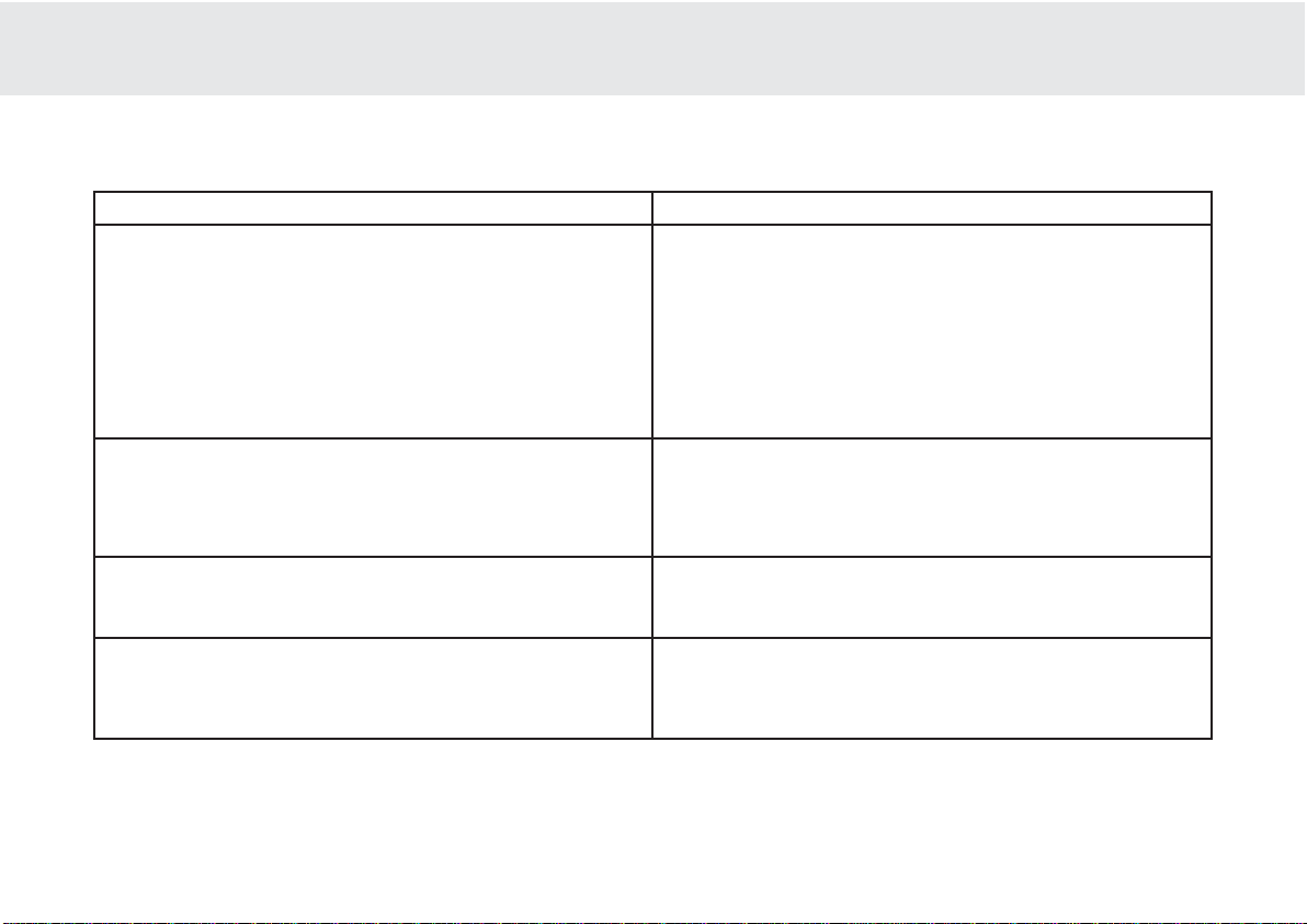
540A/640A HIFI-Verstärker
27
CAP5 hat eine zu geringe Impedanz am Lautsprecherausgang erkannt.
Überprüfen Sie die Lautsprecherterminals und Kabelverbindungen auf
mögliche Kurzschlüsse und beseitigen Sie diese ggfls.
Ist kein Kurzschluß vorhanden, liegt es möglicherweise daran, dass zu
niederohmige Lautsprecher angeschlossen sind, bzw. die
Gesamtimpedanz aus Gruppe A und Gruppe B zu niedrig ist. Entfernen
Sie deshalb ein Boxenpaar.
Sollte auch dann das Einschalten nicht möglich sein, ist eventuell das
verbliebene Boxenpaar zu niederohmig oder es liegt ein Def ekt an einem
oder beiden Lautsprechern vor.
CAP5 hat einen von Außen, bzw. durch den Benutzer v erursachten Fehler
oder eine Überlastung erkannt. Die Betriebstemperatur der Endstufe hat
einen kritischen Wert erreicht. In der Regel liegt kein Defekt im Gerät vor,
es sollte jedoch für entsprechende Abkühlung gesorgt werden. Unter
normalen Betriebsbedingungen kann der Verstärker nach ca. 15
Minuten wieder eingeschaltet werden.
CAP5 hat einen von außen, bzw. durch den Benutzer verursachten F ehler
erkannt. Möglicherweise liegt ein Kurzschluß an den
Lautsprecherausgängen vor. Überprüfen Sie alle Anschlüsse, Kabel und
Lautsprecher und beseitigen Sie die Ursache.
CAP5 hat einen internen Fehler am Gerät erkannt. Es wurde eine hohe
Gleichspannung am Lautsprecherausgang festgestellt, welche die
Lautsprecher gefährden könnte. Das Gerät ist nicht weiter benutzbar.
Trennen Sie das Gerät von Stromnetz und wenden Sie sich an Ihren
Händler oder die zuständige Servicestelle um den Fehler zu heben.
Die Protection LED blinkt für 4 Sekunden während der Verstärker
versucht aus dem Standby Modus einzuschalten.
Das Gerät hat während des Betriebes abgeschaltet. Die Protection LED
bblliinnkktt ffoorrttwwäähhrreenndd iinn ddooppppeelltteenn IInntteerrvvaalllleenn
.
Das Gerät hat während des Betriebes abgeschaltet. Die Protection LED
bblliinnkktt ffoorrttwwäähhrreenndd iinn 44 ffaacchheenn IInntteerrvvaalll
leenn
.
Das Gerät hat während des Betriebes abgeschaltet. Die Protection LED
iisstt aann uunndd ffllaacckkeerrtt mmiitt hhoohheerr FFrreeqquueennzz
.
Anzeige
Fehler // AAbhilfe
Page 28

28
Das GGerät iist oohne SStrom
Kontrollieren Sie den korrekten und festen Sitz des Netzkabels in der
Steckdose und am Gerät.
Überprüfen Sie die Funktion der Steckdose, eventuell durch Anschluß einer
Lampe oder eines anderen Gerätes.
Kein TTon üüber ddie LLautsprecher
Möglicherweise befindet sich der Verstärker noch im Standby Modus.
Schalten Sie ihn ein.
Überprüfen Sie alle Verbindungen zu den anderen Geräten und die
Lautsprecheranschlüsse.
Eventuell ist die Tape Monit or- Funktion eingeschaltet. Schalten Sie diese ab,
es sei denn, Sie möchten das Programm eines angeschlossenen Recorders
wiedergeben.
Blinkt die LED der Eingangswahl? Schalten Sie die Mute-Funktion mit der
Fernbedienung ab.
Kein TTon aauf eeinem KKanal
Überprüfen Sie alle Verbindungen zu den anderen Geräten und die
Lautsprecheranschlüsse.
Stellen Sie den Balance Regler in die Mittelposition.
Laute SStörgeräusche ooder BBrummen iin dden LLautsprechern
Überprüfen Sie verschiedene Tonquellen bezüglich der Störungen. Tritt das
Problem nur bei einer Quelle auf (z.B. CD-Player), oder sind die Störungen nur
auf einem Kanal zu hören, dann ist eventuell ein Verbindungskabel defekt.
Sind die Störungen auf beiden Kanälen zu hören, handelt es sich meistens
um Einstreuungen, verursacht durch externe Geräte oder kritische
Kabelführung.
Es kkönnen kkeine AAufnahmen ggemacht wwerden
Überprüfen Sie die Verbindungen zu den Tape In & Rec Out 1/2 Buchsen.
Diffuses KKlangbild // EEingeschränkte SStereo PPerspektive
Möglicherweise ist bei einer oder beiden Lautsprecherverbindungen die
Polung vertauscht. Kontrollieren Sie den korrekten Anschluß von + & - .
Der VVerstärker lläßt ssich nnicht aaus ddem SStandby MModus
einschalten
Beachten Sie die Hinweise zum CAP5 System auf den Seiten 12 u. 13.
PROBLEMBEHANDLUNG
Ausgangsleistung
Max.
Leistungsaufnahme
Standby
Leistungsaufnahme
THD
(ungewichtet)
Frequenzverhalten
(-33dB)
Rauschabstand
(ungewichtet)
Anstiegsgeschwindigkeit
(Slew RRate) ((an 88W ΩΩ)
Abmessungen
(HxBxT)
mm
Zoll
Gewicht
kg
Lbs
TECHNISCHE DATEN
540A 640A
100W (an 4Ω)
65W (an 8Ω)
615W
6W
1kHz < 0,005%
20kHz < 0,07%
4Hz - 80kHz
92dB
50V/uS
100 x 430 x 310
3,9 x 16,9 x 12,2
7
15,4
75W (an 4Ω)
50W (an 8Ω)
515W
6W
1kHz < 0,009%
20kHz < 0,09%
5Hz - 50kHz
92dB
30V/uS
100 x 430 x 310
3,9 x 16,9 x 12,2
7
15,4
Page 29

540A/640A HIFI-Verstärker
29
Cambridge Audio garantiert Ihnen, dass dieses Produkt keine Materialund Herstellungsfehler (wie im Folgenden näher erläutert) aufweist.
Cambridge Audio repariert oder ersetzt (nach der freien Entscheidung
von Cambridge Audio) dieses Produkt oder ein eventuelles defektes Teil
in diesem Produkt. Die Garantiedauer kann in den einzelnen Ländern
unterschiedlich sein. Wenn Sie Fragen zu der Garantie haben, wenden
Sie sich bitte an Ihren Händler. Bewahren Sie den Kaufnachweis immer
auf.
Wenn Sie Garantieleistungen in Anspruch nehmen möchten, wenden
Sie sich bitte an den von Cambridge Audio autorisierten Händler, bei
dem Sie das Produkt gekauft haben. Sollte dieser Händler nicht in der
Lage sein, Ihr Cambridge Audio-Produkt zu reparieren, kann dieser das
Produkt an Cambridge Audio oder eine autorisierte Cambridge AudioKundendienststelle zurücksenden. Das Produkt muss entweder in der
Originalverpackung oder einer Verpackung, die einen gleichwertigen
Schutz bietet, versandt werden.
Sie müssen einen Kaufnachweis in Form einer Kaufurkunde oder einer
quittierten Rechnung vorlegen, wenn Sie einen Anspruch auf
Garantieleistungen geltend machen. Aus diesem Kaufnachweis muss
abzulesen sein, dass sich das Produkt im Garantiezeitraum befindet.
Diese Garantie wird ungültig, wenn (a) die bei der Herstellung
angebrachte Seriennummer bei diesem Produkt geändert oder entfernt
wurde oder (b) dieses Produkt nicht bei einem von Cambridge Audio
autorisierten Händler gekauft wurde. Wenden Sie sich an Cambridge
Audio oder den lokalen Cambridge Audio-Vertrieb in Ihrem eigenen
Land, um sicher zu stellen, dass Ihre Seriennummer nicht geändert
wurde und/oder dass Sie bei einem von Cambridge Audio autorisierten
Händler gekauft haben.
Die Garantie gilt nicht für kosmetische Schäden oder Schäden durch
höhere Gewalt, Unfälle, unsachgemäße Behandlung, Unachtsamkeit,
kommerziellen Einsatz oder durch Änderungen des Produkts bzw. von
Teilen des Produkts. Diese Garantie umfasst keine Schäden durch
unsachgemäßen Betrieb, unsachgemäße Wartung oder Installation
oder durch Reparaturen, die von anderen Personen als von Cambridge
Audio oder einem Cambridge Audio-Händler oder einem autorisierten
Kundendienstmitarbeiter, der von Cambridge Audio für das Ausführen
von Garantieleistungen befugt ist, vorgenommen werden. Durch jede
nicht autorisierte Reparatur wird diese Garantie unwirksam. Diese
Garantie gilt nicht für Produkte, die verkauft werden AS IS (WIE SIE
SIND) oder WITH ALL FAULTS (MIT ALLEN FEHLERN).
DIE HAFTUNGSANSPRÜCHE DES BENUTZERS BESCHRÄNKEN SICH AUF
DIE IN DIESER GARANTIE ENTHALTENEN REPARATUREN ODER
ERSATZLEISTUNGEN. CAMBRIDGE AUDIO HAFTET NICHT FÜR
ZUFÄLLIGE ODER FOLGESCHÄDEN DURCH DIE VERLETZUNG
IRGENDEINER AUSDRÜCKLICHEN ODER IMPLIZITEN GARANTIE BEI
DIESEM PRODUKT. A UßER DORT, WO DIES GESETZLICH UNTERSAGT IST,
IST DIESE GARANTIE EXKLUSIV UND TRITT SIE AN DIE STELLE ALLER
ANDEREN AUSDRÜCKLICHEN ODER IMPLIZITEN GARANTIEN, WELCHER
ART AUCH IMMER, EINSCHLIEßLICH, ABER NICHT BESCHRÄNKT AUF,
VERKAUFSGARANTIE UND FUNKTIONSGARANTIE FÜR EINEN
PRAKTISCHEN ZWECK.
Einige Länder und US-Staaten erlauben keinen Ausschluss oder keine
Beschränkung von zufälligen oder Folgeschäden bzw. impliziten
Garantien, so dass die oben genannten Ausschlüsse für Sie eventuell
nicht gelten. Diese Garantie erteilt Ihnen spezifische gesetzliche Rechte;
es ist auch möglich, dass Sie andere Rechtsansprüche haben, die in
jedem Staat und jedem Land anders aussehen können.
HAFTUNGSBESCHRÄNKUNG
Page 30

30
Merci dd'avoir aacheté ccet aamplificateur CCambridge AAudio dde lla ggamme
Azur. CCet aamplificateur eest lle ppro
duit dde ll'un dde nnos pprogrammes dde
recherche eet dde ddéveloppement lles pplus aambitieux ddepuis qque nnous
fabriquons ddes pproduits aaudio dde hhaute qqualité, ssoit ddepuis pplus dde 330
ans. NNous eespérons qque vvous aapprécierez sses rrésultats eet qque vvous
pourrez pprofiter llongtemps dde sses qqualités ssonores eexceptionnelles.
A ppropos dde ccet aamplificateur
Le processus de conception d'un ampli audio haute qualité nécessite que l'on
porte une attention particulière à deux éléments principaux : l'alimentation
électrique et la capacité de l'étage d'excitation à fournir un étage de sortie
efficace. A Cambridge Audio, nos travaux de recherche ont toujours eu pour but
d'atteindre le meilleur niveau de performance dans ces domaines, à un prix
abordable. La topologie de l'Azur 540A/640A utilise les mêmes périphériques de
sortie testés et approuvés utilisés par Cambridge Audio dans ses anciens modèles
primés d'amplificateurs, avec de nombreuses heures de recherche et de
développement consacrées aux étages précédents. Les circuits de l'amplificateur
sont essentiellement composés d'une paire d'entrées pour courant en rapport
géométrique chargées par un miroir de courant et excitées par une source de
courant transitoire compensé, pilotant un étage de gain en tension en cascade
(béta élevé). L'étage de sortie compensé thermiquement a été réglé pour donner
des conditions optimales de classe AB (pour une distorsion de croisement
grandement réduite causée par le réchauffement dynamique en cas de panne de
la sortie). De plus, la topologie inclut une amélioration supplémentaire de l'étage
d'excitation : un montage suiveur de classe A conçu pour isoler les transistors de
l'amplificateur de tension de la lourde charge des transistors de sortie. Cette
augmentation de l'excitation de l'étage de sortie, combinée à un nouveau circuit
avant à régime transitoire, permet de doubler la vitesse de balayage à 40V/uS.
Grâce à une topologie intelligente des cartes de circuits imprimés, à un placement
judicieux des composants et à des chemins de signaux très courts, nos
amplificateurs offrent une stabilité exceptionnelle, ce qui permet de diminuer la
taille des composants de compensation. Ceci permet de diminuer les effets de
distorsion, d'augmenter la dynamique et d'obtenir une bande passante très
importante (80kHz), un avantage idéal pour les sources à bande passante élevée
'meilleures que les CD', comme les DVD-Audio et les Super Audio CD.
Tout amplificateur v oit ses performances limitées par les aptitudes dynamiques de
son alimentation électrique. Pour cette raison, les amplificateurs de la gamme
Cambridge Azur incorporent un grand nombre de caractéristiques, notamment un
transformateur toroïdal à faible flux, une mise en parallèle des condensateurs
réservoirs et l'utilisation judicieuse des condensateurs de dérivation, afin de
permettre un rendu propre de la charge aux moments les plus opportuns. On
obtient ainsi la reproduction d'un son ouvert et naturel, tout en assurant une
réponse positive en cas de changement soudain du signal reproduit.
Nous avons également porté une attention particulière à la qualité des
composants passifs, qui ont été soigneusement sélectionnés pour leurs
avantages sonores. De plus, l'Azur 640A utilise des condensateurs de dérivation
de signaux en polypropylène haute qualité afin d'améliorer le traitement
dynamique et la circulation des signaux.
Les amplificateurs Cambridge Audio Azur 540A et 640A offrent également des
commandes de tonalité pouvant être déconnectées d'un circuit en mode 'direct'
pour un trajet du signal le plus court et donc le plus pur. Parmi les autres
caractéristiques de ces amplificateurs, on notera des prises phono plaqué or 24k,
des boucles doubles pour magnétophone, une sortie préampli, une prise pour le
casque et une série secondaire de terminaux haut-parleurs haut niveau.
Une nouvelle caractéristique est offerte en standard sur le 540A et le 640A: le
système novateur de protection CAP5 conçu par Cambridge Audio. Ce système est
composé d'un microprocesseur de contrôle continu de l'amplificateur, fournissant
ainsi une protection générale contre toute une gamme de défauts possibles. Le
système a été obtenu sans l'ajout de circuits actifs supplémentaires dans le trajet
du signal, permettant ainsi de ne pas altérer les qualités sonores ou les aptitudes
dynamiques de l'amplificateur.
Après de longues heures d'écoute et de peaufinage, Cambridge Audio dispose
désormais de connaissances très vastes et très pointues. Cette attention aux
INTRODUCTION
Page 31

540A/640A Amplificateur intégré
31
détails a permis de créer des amplificateurs offrant une reproduction vraiment
convaincante de la couleur tonale et du contraste dynamique, pour des
performances vivantes et fluides, quel que soit le style de musique écouté.
Pour maximiser les performances de cet appareil, nous vous recommandons de
n'utiliser que des composants source de haute qualité. Bien entendu, nous
recommandons en particulier les tuners et les équipements numériques de la
gamme Cambridge Audio, ceux-ci ayant été fabriqué en respectant des normes de
qualité tout aussi élevées que nos amplificateurs. Un grand nombre de hautparleurs ont été utilisés lors du développement de nos amplificateurs afin
d'assurer une compatibilité maximale avec une grande variété de modèles.
Les câbles d'interconnexion et de raccord aux haut-parleurs sont également très
importants. Evitez de compromettre les performances de votre système en
utilisant des câbles de qualité inférieure pour connecter les composants sources
à votre amplificateur ou les sorties de votre amplificateur à vos haut-parleurs. Ne
laissez pas un maillon faible compromettre la qualité d'ensemble de votre
système. Pour cette raison, nous n'incluons pas des câbles bon marché en
'cadeau' et ce quel que soient nos produits. Votre revendeur peut vous fournir des
câbles d'interconnexion Cambridge Audio et des câbles pour haut-parleurs
Mordaunt Short/Gale de bonne qualité. Ceux-ci vous permettront d'améliorer
sensiblement la qualité sonore de votre système.
VVoouuss nn''aavveezz mmaaiinntteennaanntt pplluuss qquu''àà vvoouuss ddéétteennddrree eett àà aapppprréécciieerr llaa qquuaalliittéé ddee nnooss
pprroodduuiittss !!
Matthew Bramble
Technical Director
Introduction...............................................................................................30
Consignes de sécurité .............................................................................32
Remarques sur l'installation.....................................................................33
Connexions Panneau arrière ..................................................................34
Schémas de connexion............................................................................36
Mode d'emploi.......................................................................................... 38
CAP5 - Systeme de protection a 5 voies.................................................40
Dépannage............................................................................................... 42
Spécifications techniques ......................................................................42
Garantie limitée....................................................................................... 43
SOMMAIRE
Page 32

32
Vérification dde lla ppuissance dde ll'alimentation
Pour votre propre sécurité, veuillez lire attentivement les présentes instructions
avant de raccorder cet appareil au secteur.
Vérifiez la tension d'alimentation à l'arrière de l'appareil. Si la tension de
l'alimentation secteur n'est pas identique, contactez votre revendeur.
Cet appareil est conçu pour fonctionner exclusivement avec une alimentation en
courant électrique correspondant aux caractéristiques de tension et de type
indiquées sur le panneau arrière. Toute autre alimentation en courant peut
endommager l'appareil.
Cet appareil doit être éteint s'il n'est pas utilisé. En outre, il ne doit être utilisé que
s'il est raccordé à la terre. Afin de réduire le risque de choc électrique, n'ouvrez pas
l'appareil (capot ou panneau arrière). L'appareil ne contient aucune pièce
nécessitant l'intervention de l'utilisateur. Pour toute réparation, adressez-vous à
un technicien-réparateur qualifié. Si le cordon d'alimentation est muni d'une fiche
moulée, l'appareil ne doit être utilisé que si le porte-fusible en plastique est en
place. Si vous perdez le porte-fusible, vous devrez commander la pièce adéquate
auprès de votre revendeur Cambridge Audio.
Le symbole de l'éclair terminé par une tête de flèche à l'intérieur d'un
triangle est destiné à avertir l'utilisateur de la présence de " tensions
dangereuses " sans isolation dans le boîtier de l'appareil, qui
peuvent être suffisamment élevées pour constituer un risque de
choc électrique pour les personnes.
Le point d'exclamation à l'intérieur d'un triangle est destiné à avertir
l'utilisateur de la présence d'instructions d'utilisation ou d'entretien
importantes dans la documentation fournie avec cet appareil.
Ce produit est conforme aux directives européennes relatives à la
basse tension (73/23/EEC) et à la compatibilité
électromagnétique (89/336/EEC) dans le cadre d'une utilisation
et une installation conformes à ce mode d'emploi. Par respect
des normes de conformité, seuls les accessoires Cambridge
Audio doivent être utilisés avec ce produit. Pour tout entretien ou
toute réparation, veuillez vous référer à un technicien qualifié.
CONSIGNES DE SÉCURITÉ
Page 33

540A/640A Amplificateur intégré
33
Veuillez prendre quelques minutes pour lire ces notes avant d'installer
votre amplificateur. Vous pourrez ainsi obtenir des performances
optimales et prolonger la vie de votre produit.
Il est nécessaire de laisser un espace de ventilation au-dessus et en
dessous de l'amplificateur. N'installez pas l'amplificat eur sur un tapis ou
sur une surface non dure et n'obstruez pas l'entrée d'air et les grilles de
ventilation situées en dessous et sur le couvercle de l'amplificateur. Ne
mettez pas l'amplificateur dans un espace clos comme une bibliothèque
ou un meuble de rangement fermé.
Ne laissez jamais l'amplificateur en contact avec de l'eau ou avec tout
autre liquide et faites attention à ce que de petits objets ne tombent pas
à travers la grille de ventilation. Si c'était le cas, éteignez
immédiatement l'appareil, débranchez l'alimentation principale et
contactez votre revendeur pour lui demander conseil.
Ne mettez pas le cordon d'alimentation à un endroit où on risque de
marcher dessus ou là où d'autres objets risquent de l'endommager.
Les composants électroniques audio ont une période de rodage
d'environ une semaine (pour une utilisation de plusieurs heures par
semaine). Ceci permet aux nouveaux composants de se mettre en
place, les propriétés sonores s'améliorant au fil du temps.
En cas de bi-amplification, nous vous recommandons d'utiliser des
amplificateurs de puissance de même type.
Cet amplificateur a été conçu pour être laissé en mode Veille lorsqu'il
n'est pas utilisé. Ceci permet d'augmenter la durée de vie de votre
appareil (et s'applique d'ailleurs à tout autre équipement électronique).
Si vous ne comptez pas utiliser cet amplificateur pendant une période
de temps prolongée, éteignez-le et débranchez la prise de l'alimentation
principale.
Pour nettoyer l'amplificateur, utilisez un chiffon légèrement humidifié et
qui ne peluche pas pour nettoyer le boîtier. N'utilisez pas de liquides de
nettoyage contenant de l'alcool ou de l'ammoniac, ni de produits
abrasifs. N'utilisez pas de vaporisateur sur l'amplificateur , ni à pr oximité.
L'entretien de ces amplificateurs n'est pas destiné aux utilisateurs.
N'essayez jamais de réparer, de démonter ou de remonter l'appareil si
celui-ci semble présenter un problème. Si cette consigne de sécurité
n'est pas respectée, vous risqueriez de vous exposer à un choc
électrique grave. En cas de problème ou de panne, veuillez contacter
votre revendeur.
Cet appareil doit être installé sur une surface stable et plane. En raison
de la création de champs magnétiques rayonnés, les platines tournedisques ne doivent pas être installées à proximité pour éviter toute
interférence.
INSTALLATION
Page 34

34
Prise dde ccourant aalternatif
Après avoir effectué toutes les connexions à l'am plificateur, branchez la prise
de courant alternatif à une prise d'alimentation adéquate. L'amplificateur est
désormais prêt à être utilisé.
Connexions hhaut-pparleurs
Le 540A et le 640A sont équipés de deux séries de bornes Haut-parleurs :
Haut-parleur A et B (Speaker A et Speaker B). Le Haut-parleur A est la borne
de haut-parleurs principale, Haut-parleur B la borne secondaire et
commutable. Connectez les fils de votre haut-parleur gauche aux bornes
LEFT + & -. Procédez de même avec les fils de votre haut-parleur droit aux
bornes RIGHT + & -. Dans chacun des cas, la borne rouge correspond à la
sortie positive, la borne noire à l'entrée négative. On prendra soin à ce que
des fils non raccordés ne fassent pas court-circuit avec les sorties des hautparleurs.
NB :: CCet aamplificateur aa éété cconçu ppour êêtre uutilisé aavec ddes hhaut-pparleurs
d'une iimpédance nnominale
ccomprise eentre 44 eet 88 oohms.
Veuillez vvous aassurer qque lles bbornes ddes hhaut-pparleurs oont bbien éété
resser
rées aafin dde ffournir uune cconnexion éélectrique aadéquate. LLa qqualité
sonore sse ttrouve pparfois aaffectée ssi lles bbornes àà vvis nne ssont ppas bbien vvissées.
Sorties ppre-aamplificateur
Connectez ces prises aux entrées d'un/de plusieurs amplificateur(s) de
puissance externe(s).
TAPE mmon ((Moniteur CCASSETTE)
Ces prises peuvent être connectées à une platine de magnétophone ou aux
prises analogiques d'un enregistreur de CD ou de MiniDiscs. Connectez un
T
2
T
R
2
M
:
P
Pre-Out
I
Impedance 4 - 8 ohms
L
Loudspeaker Terminals
Important
P
Please ensure that loudspeaker terminals are fully tightened
Veuillez s'assurer que les bornes de l'enceinte sont entierement serreesVeuillez s'assurer que les bornes de l'enceinte sont entierement serrees
I
Impedance 4 - 8 ohms
R
Right
L
Left
R
Right
L
Left
Left
R
Right
L
Left
R
Right
B
B
A
A
AV / MD
T
Tuner / DAB
o
Aux / Phono
P
Pre-Out
AV / MD
DVDDVD
Tuner / DAB
C
CD
A
Aux / Phono
R
Right
L
Left
RightRight
L
Left
d
Ground
w
k
www.cambridge-audio.co.uk
M
Manufactured in an
I
2
ISO9002
approved facility
P
C
Power AC
D
Designed and Engineered in London, England
R
k
Risk of electric shock
D
n
Do not open
C
Caution
Risque de choc electrique
Ne pas ouvrir
Vorm offnen des geratesVorm offnen des gerates
N
Netzstecker ziehen
Achtung
a
r
azur 640A Integrated Amplifier
Power Rating:
230V AC 50Hz
230V AC 50Hz
CONNEXIONS PANNEAU ARRIÈRE
zur 640A Integrated Amplifie
Power Rating:
ax Power Consumption
isk of electric shoc
aution
o not ope
Avis
Risque de choc electrique
Ne pas ouvrir
Achtung
etzstecker ziehen
ower A
ww.cambridge-audio.co.u
anufactured in an
SO900
615W
approved facility
ight
ight
A
oudspeaker Terminals
lease ensure that loudspeaker terminals are fully tightened
eft
eft
mpedance 4 - 8 ohms
Important
mpedance 4 - 8 ohms
ight
ight
Left
eft
esigned and Engineered in London, England
Groun
re-Out
ape In
ec Out 1
eft
ape InRec Out 1Rec Out
re-Out
AV / MD
Rec Out
AV / MD
uner / DAB
Tuner / DAB
D
CDCDAux / Phon
ux / Phono
eft
ight
Page 35

540A/640A Amplificateur intégré
35
câble d'interconnexion des prises LINE OUT (sortie haut-niveau) de
l'enregistreur aux prises TAPE MONitor de l'amplificateur. Ce moniteur sert
également d'entrée standard cassette/enregistreur.
NB :: LLorsque vvous cconnectez uun ccomposant ssource ééquipé dd'une eentrée eet
d'une ssortie ((c'est-àà-ddire uun
mmagnétophone), lla ssortie dde ccelui-cci ddoit ttoujours
être cconnectée àà ll'entrée TTAPE MMON. CCeci ppermet dd'
éviter ttout aaccrochage
acoustique aau ccas ooù lla mmauvaise vvoie dd'entrée sserait ssélectionnée.
Tape oout ((Sortie ccassette)
Ces prises peuvent être connectées à un magnétophone ou aux prises
analogiques d'un enregistreur de CD ou de MiniDiscs. Connectez un câble
d'interconnexion des prises TAPE OUT (sortie cassette) de cet amplificateur à
l'entrée LINE IN de l'enregistreur. Veuillez noter que cet amplificateur est
équipé de deux boucles magnétophone avec des sorties identiques.
Prises dd'entrée CCD/Tuner/DVD/AV/MD
Ces entrées peuvent être utilisées pour tout équipement source de 'niveau
de ligne' comme les lecteurs CD, DAB, les tuners FM/AM, etc.
Prises dd'entrée AAUX/PHONO
Connectez à ces prises tout équipement source de 'niveau de ligne', par ex.
lecteur CD ou tuner DAB. Cette entrée bien précise peut également être
convertie si nécessaire pour un tourne-disque dédié. A cette fin, l'installation
d'un module Phono PM01 Cambridge Audio est cependant nécessaire.
Veuillez contacter votre revendeur Cambridge Audio qui pourra vous fournir
un étage phono pour votre amplificateur et vous l'installer.
NB :: CCes eentrées ssont ddestinées aaux ssignaux aaudio aanalogiques uuniquement.
Elles nne ddoivent ppas êêtre c
connectées àà uune ssortie nnumérique dd'un llecteur dde
CD, nni àà ttout aautre aappareil nnumérique.
Ground cconnection ((Terre)
Si vous connectez un tourne-disque à votre amplificateur, connectez son fil
de terre à cette borne.
Page 36

36
Lorsque nous avons conçu nos amplificateurs, nous avons essayé
d'inclure des caractéristiques vous permettant de connecter votre
système de différentes façons. Avec des connexions comme PRE-OUT
(pré-sortie) et SPEAKER B (haut-parleur B), vous pourrez configurer
votre amplificateur en fonction de vos besoins. Les schémas des pages
suivantes ont été conçus pour vous faciliter ces connexions.
Connexions dde bbase
Ce schéma indique les connexions de base à effectuer entre votre
amplificateur et un lecteur de CD et une paire de haut-parleurs.
Connexions aa uun mmagnetophone
Ce schéma indique les connexions à effectuer pour relier votre
amplificateur à un enregistreur de cassettes ou à une autre source
équipée d'une connexion pour l'enregistrement et le réglage. Veuillez
noter qu'il est possible d'utiliser l'une ou l'autre des deux sorties
magnétophone (celles-ci étant les mêmes).
CONNEXIONS
M
:
t
Pre-Out
Impedance 4 - 8 ohms
Loudspeaker Terminals
Important
P
Please ensure that loudspeaker terminals are fully tightened
Veuillez s'assurer que les bornes de l'enceinte sont entierement serrees
Veuillez s'assurer que les bornes de l'enceinte sont entierement serrees
Impedance 4 - 8 ohms
R
Right
Left
R
Right
Left
Left
L
Left
Righ
Right
L
Left
Right
B
B
A
R
1
Rec Out 1
R
2
Rec Out 2
T
n
Tape In
AV / MD
Tuner / DAB
CD
A
o
Aux / Phono
P
Pre-Out
R
RecOut 1
R
2
RecOut 2
T
n
Tape In
AV / MD
AV / MD
DVD
DVD
Tuner / DAB
CDCD
Aux / Phono
R
Right
Left
Left
R
Right
L
Left
G
d
Ground
w
www.cambridge-audio.co.uk
M
Manufactured in an
2
ISO9002
y
approved facility
P
Power AC
D
d
Designed and Engineered in London, England
R
Risk of electric shock
D
n
Do not open
Caution
Caution
e
Risque de choc electrique
Ne p
Ne pas ouvrir
Avis
Vorm offnen des gerates
Vorm offnen des gerates
N
n
Netzstecker ziehen
Ach
g
Achtung
a
azur 640A Integrated Amplifier
Power Rating:
230V AC 50Hz
230V AC 50Hz
T
1
R
2
T
R
2
M
:
tPre-Out
Impedance 4 - 8 ohms
Loudspeaker Terminals
Important
P
Please ensure that loudspeaker terminals are fully tightened
Veuillez s'assurer que les bornes de l'enceinte sont entierement serrees
Veuillez s'assurer que les bornes de l'enceinte sont entierement serrees
Impedance 4 - 8 ohms
R
Right
Left
R
Right
Left
Left
L
Left
Righ
Right
L
Left
Right
B
B
A
A
AV / MD
Tuner / DAB
CD
A
o
Aux / Phono
P
Pre-Out
AV / MD
AV / MD
DVD
DVD
Tuner / DAB
CDCD
Aux / Phono
R
Right
Left
Left
R
Right
L
Left
G
d
Ground
w
www.cambridge-audio.co.uk
M
Manufactured in an
2
ISO9002
y
approved facility
P
Power AC
D
d
Designed and Engineered in London, England
R
Risk of electric shock
D
n
Do not open
Caution
Caution
e
Risque de choc electrique
Ne p
Ne pas ouvrir
Avis
Vorm offnen des gerates
Vorm offnen des gerates
N
n
Netzstecker ziehen
Ach
g
Achtung
a
azur 640A Integrated Amplifier
Power Rating:
230V AC 50Hz
230V AC 50Hz
Rec InRec Out
Platine ccassette // MMD
zur 640A Integrated Amplifier
Power Rating:
ax Power Consumption
isk of electric shock
o not ope
Risque de choc electriqu
as ouvrir
tun
etzstecker ziehe
ower AC
ww.cambridge-audio.co.uk
anufactured in an
ISO900
615W
approved facilit
Impedance 4 - 8 ohms
eft
Right
A
t
ight
Left
ight
Impedance 4 - 8 ohms
Loudspeaker Terminals
Important
lease ensure that loudspeaker terminals are fully tightened
eft
re-Out
eft
ight
ec Out
Pre-Ou
esigned and Engineered in London, Englan
ec Out 1
ape I
ec Out
ec Out
ape I
AV / MD
roun
Tuner / DAB
Aux / Phono
Tuner / DAB
ight
CD
ux / Phon
zur 640A Integrated Amplifier
Power Rating:
ax Power Consumption
615W
isk of electric shock
o not ope
Risque de choc electriqu
as ouvrir
tun
etzstecker ziehe
ower AC
ww.cambridge-audio.co.uk
anufactured in an
ISO900
approved facilit
Impedance 4 - 8 ohms
eft
Right
t
ight
Left
ight
Impedance 4 - 8 ohms
Loudspeaker Terminals
Important
lease ensure that loudspeaker terminals are fully tightened
eft
re-Out
eft
ight
ape In
Pre-Ou
ape In 1
ec Out 1
ec Out 1Rec Out
esigned and Engineered in London, Englan
Rec Out
AV / MD
roun
Tuner / DAB
Aux / Phono
Tuner / DAB
ight
CD
ux / Phon
Page 37

540A/640A Amplificateur intégré
37
Bi-aamplification
Si votre amplificateur est équipé de prises PRE-OUT et que vos hautparleurs possèdent deux séries de bornes, il est alors possible de biamplifier votre système à l'aide d'un autre amplificateur de puissance
(voir figures 4, 6 & 7). La bi-amplification utilise deux amplificateurs
pour faire passer indépendamment les graves et les aigus dans les
haut-parleurs. Ceci permet d'obtenir un son encore mieux défini et
d'améliorer les possibilités de réglage et de dynamique du système.
Utilisation ddes cconnexions SSpeaker BB ((haut-pparleur BB)
Les connexions SPEAKER B à l'arrière de l'amplificateur permettent
d'utiliser une deuxième paire d'enceintes, à placer si vous le désirez
dans une autre pièce.
2
R
1
R
2
M
n
:
W
P
Pre-Out
I
Impedance 4 - 8 ohms
L
Loudspeaker Terminals
Important
P
Please ensure that loudspeaker terminals are fully tightened
Veuillez s'assurer que les bornes de l'enceinte sont entierement serrees
Veuillez s'assurer que les bornes de l'enceinte sont entierement serrees
I
s
Impedance 4 - 8 ohms
R
Right
L
Right
L
Left
Right
Right
Left
Right
Right
B
B
A
A
AV / MD
B
Tuner / DAB
CDCD
o
Aux / Phono
P
Pre-Out
AV / MD
AV / MD
DVD
DVD
Tuner / DAB
CDCD
o
Aux / Phono
t
Right
Left
R
Right
L
Left
d
Ground
w
www.cambridge-audio.co.uk
M
Manufactured in an
I
2
ISO9002
y
approved facility
P
C
Power AC
D
Designed and Engineered in London, England
R
D
Do not open
Caution
Caution
e
Risque de choc electrique
Ne p
Ne pas ouvrir
Avis
Avis
Vorm offnen des gerates
Vorm offnen des gerates
N
Netzstecker ziehen
g
Achtung
r
azur 640A Integrated Amplifier
Power Rating:
230V AC 50Hz
230V AC 50Hz
Rec Out 1
R
2
T
n
Rec Out 1
Rec Out 2
P
Pre-Out
Imp
Impedance 4 - 8 ohms
L
Loudspeaker Terminals
Important
P
Please ensure that loudspeaker terminals are fully tightened
Veuillez s'assurer que les bornes de l'enceinte sont entierement serrees
Veuillez s'assurer que les bornes de l'enceinte sont entierement serrees
Imp
s
Impedance 4 - 8 ohms
Righ
Right
L
Right
L
Left
B
t
Right
Left
Right
Right
B
B
A
AV / MD
B
Tuner / DAB
CDCD
o
Aux / Phono
P
Pre-Out
AV / MD
DVD
DVD
T
DAB
Tuner / DAB
CDCD
A
o
Aux / Phono
t
Right
R
Right
L
Left
d
Ground
w
www.cambridge-audio.co.uk
M
Manufactured in an
I
2
ISO9002
approved facility
P
C
D
Designed and Engineered in London, England
R
D
Do not open
C
n
Caution
e
Risque de choc electrique
Ne pas ouvrir
Avis
Avis
Vorm offnen des gerates
Vorm offnen des gerates
N
Netzstecker ziehen
g
Achtung
r
azur 640A Integrated Amplifier
Power Rating:
230V AC 50Hz
230V AC 50Hz
M
n
Max Power Consumption
:
:
W
615W
Amplificateur mmaître
Amplificateur eesclave
- s'il s'agit d'un amplificateur intégré, le volume doit être au maximum
Lecteur dde CCD
Graves Graves
Aiguës Aiguës
azur 640A Integrated Amplifie
Power Rating:
ax Power Consumptio
615
isk of electric shock
autio
o not open
Risque de choc electriqu
Ne pas ouvrir
Achtun
etzstecker ziehen
ower A
ww.cambridge-audio.co.uk
anufactured in an
SO900
approved facility
azur 640A Integrated Amplifie
Power Rating:
ax Power Consumptio
615
isk of electric shock
o not open
Risque de choc electriqu
as ouvrir
Achtun
etzstecker ziehen
ower A
ww.cambridge-audio.co.uk
anufactured in an
SO900
approved facilit
edance 4 - 8 ohm
Left
A
A
oudspeaker Terminals
mpedance 4 - 8 ohms
oudspeaker Terminals
eftRight
edance 4 - 8 ohms
Important
Left
eftRight
Important
mpedance 4 - 8 ohm
eft
re-Out
eft
ight
Left
eft
Left
eft
ight
re-Out
re-Out
re-Out
Tape In
Tape InRec Out 1Rec Out
esigned and Engineered in London, England
ec Out
ec Out
ec Out
AV / MD
AV / MD
esigned and Engineered in London, England
AV / MD
ape I
Tape In
Groun
uner /
ux / Phon
Left
Tuner / DA
Tuner / DA
Righ
Aux / Phon
Groun
Tuner / DAB
Aux / Phon
Left
Righ
Aux / Phon
Righ
t
lease ensure that loudspeaker terminals are fully tightened
ight
lease ensure that loudspeaker terminals are fully tightened
Page 38

38
Veuillez vvous rréférer aau sschéma aaccompagnant vvotre CCertificat ddu
propriétaire.
Standby ((Veille)
Cette commande permet de faire passer votre amplificateur du mode
Veille au mode Marche (ON).
Prise ppour lle ccasque
Ceci vous permet de connecter un casque équipé d'une prise ¼".
Lorsque le casque est connecté, le relais haut-parleurs déconnecte la
sortie aux haut-parleurs (Speaker A et Speaker B).
Speaker BB oon/off ((Haut-pparleur BB mmarche/arrêt)
Cette commande permet d'activer/de désactiver la deuxième paire de
bornes pour haut-parleurs située sur le panneau arrière. Cette paire de
bornes peut être utilisée pour installer une deuxième paire de hautparleurs dans une autre pièce.
NB : Prendre les précautions nécessaires lors de la sélection de deux
haut-parleurs pour chaque voie. Si la résistance combinée mesurée sur
les bornes des haut-parleurs n'est pas assez importante, l'amplificateur
risque de rester en mode veille jusqu'à ce que la résistance de charge
suffisante soit détectée. Pour tout complément d'informations, veuillez
vous référer au chapitre sur le système de protection CAP5.
Si vvous uutilisez ddeux ppaires dde hhaut-pparleurs, vvérifiez qque cchaque ppaire
a aau mmoins uune iimpédance d
de 66 oohms ((ou pplus). LLes hhaut-pparleurs dde 44
ohms nne ssont ppas rrecommandés llors dde ll'utilisation dde pplusieurs ppaires
de hhaut-pparleurs.
Direct
Cette commande donne au signal audio un chemin plus direct vers
l'amplificateur de puissance, en évitant les circuits de réglage de la
tonalité, pour une qualité du son encore plus pure.
MODE D'EMPLOI
Volume
azur 640A
Integrated Amplifier
TrebleBass
Standby / On
Protection
Direct
Speaker BPhones
Balance
Aux / Phono
CD
DVD
Tape Mon
AV / MDTuner / DAB
Page 39

540A/640A Amplificateur intégré
39
Commandes dde rreglage dde lla ttonalite ggrave && aaigue
Ces commandes permettent d'effectuer des ajustements très fins à la
balance de tonalité du son. En position centrale, ces commandes n'ont
aucun effet. Ces commandes ne font que modifier le son à travers vos
haut-parleurs et les prises PRE-OUT (si elles sont utilisées). Elles
n'affectent pas les signaux envoyés à travers les connexions TAPE OUT
(sortie magnétophone). Avec un bon système et un CD bien produit, ces
commandes de réglage de la tonalité ne sont pas nécessaires et peuvent
être éteintes. Si l'enregistrement musical est de mauvaise qualité et/ou les
haut-parleurs/l'environnement ne sont pas optimaux, il est parfois
nécessaire d'ajuster ces commandes pour compenser ces imperfections.
Capteur iinfrarouge
Ce capteur reçoit les signaux infra-rouges de la télécommande.
Volume
Le contrôle du volume permet d'augmenter/de diminuer l'intensité sonore
des sorties de l'amplificateur. Cette commande affecte les niveaux de sortie
Haut-parleur, Pré-ampli et Casque. Elle n'affecte pas les conne xions Tape Out
(sortie magnétophone).
NB : Il est recommandé de tourner entièrement le bouton de commande du
VOLUME dans le sens contraire des aiguilles d'une montre avant d'allumer
l'amplificateur.
Balance
Cette commande permet d'équilibrer les niveaux de sortie relative des voies
droite et gauche. En position centrale, la sortie est égale pour chaque voie.
Cette commande ne fait que modifier le son émis par vos haut-parleurs et les
prises PRE-OUT (si cela s'applique). Elle n'affecte pas les signaux envoyés par
les connexions TAPE OUT (sortie magnétophone).
Boutons ppoussoirs dde sselection dd'entree
Appuyez sur les boutons-poussoirs de sélection d'entrée appropriés pour
sélectionner la/les source(s) que vous désirez écouter. Le signal sélectionné
est également transmis aux prises TAPE OUT (sortie magnétophone) de
façon à pouvoir l'enregistrer. L'entrée ne doit pas être modifiée lors de
l'enregistrement. Cependant, il est possible de vérifier le signal enregistré en
utilisant le bouton d'entrée TAPE MONITOR de contrôle du magnétophone.
Bouton dde ssélection TTAPE MMONITOR ((Contrôle ddu
magnétophone)
Ce bouton vous permet d'écouter le signal de sortie d'un magnétophone ou
d'un processeur audio connecté aux prises TAPE MON de cet amplificateur.
En sélectionnant TAPE MON, la source sélectionnée par le bouton-poussoir
de sélection d'entrée continue à être dirigée vers les prises TAPE OUT pour
l'enregistrement ou le traitement audio.
Caractéristiques/mode dd'emploi dde lla ttélécommande
Cet amplificateur est fourni avec une télécommande q ui permet de contrôler
à la fois cet amplificateur et les lecteurs CD Cambridge Azur. Les fonctions
correspondant à cet amplificateur sont les suivantes :
Power ((Alimentation) -
Permet de faire passer votre amplificateur du mode
Standby (veille) au mode On (marche). La diode lumineuse bleue
correspondant au mode veille sur le panneau avant de l'amplificateur
indique que cet appareil est en mode Veille.
Mute ((Sourdine) -
Ce bouton permet de mettre l'audio en sourdine. En mode
Sourdine, la diode lumineuse clignote.
Volume ++/-
- Ces boutons de volume permettent de monter ou de baisser le
volume de la sortie de l'amplificateur.
Channel SSelect ((Sélection ddu ccanal) -
Les cinq boutons de sélection du canal
et le bouton de sélection Tape Monitor servent à modifier l'entrée utilisée.
Page 40

40
NB : Si l'impédance des haut-parleurs est trop basse, la température de
l'amplificateur risque d'augmenter plus rapidement, l'amplificateur ay ant une charge
plus importante. Si l'amplificateur est placé à l'intérieur d'un meuble fermé ou si les
fentes de ventilation sont obstruées, la fonction de détection de température
excessive risque de s'activer/se désactiver après un temps d'écoute assez court.
Détection dde ccourt-ccircuit
A l'allumage à partir du mode veille ou à la sélection du canal d'entrée, le CAP5
effectue une vérification sur les bornes des haut-parleurs pour déterminer si un
court-circuit a été introduit de façon accidentelle. Si la résistance mesurée aux
bornes des haut-parleurs est trop faible, l'amplificateur reste alors en mode Veille
jusqu'à ce que ce défaut soit corrigé et que l'amplificateur soit remis sous tension.
Détection CCC
Le système CAP5 offre une protection des haut-parleurs si la sortie de
l'amplificateur passe en courant continu en raison d'un défaut interne. C'est un
défaut très rare, mais cette protection pourrait éviter que des haut-parleurs très
onéreux ne soient endommagés. Le système CAP5 contrôle constamment la
différence entre le signal d'entrée et le signal de sortie. Si celle-ci passe
soudainement à un niveau très élevé, le relais Haut-parleurs est alors coupé en
quelques microsecondes.
NB : si vous mettez l'amplificateur du mode Veille au mode Mar che et que le signal
d'entrée à l'amplificateur est trop élevé (avec le réglage de volume actuel), le
système CAP5 détecte automatiquement ce problème et réduit le volume à un
niveau convenable.
Détection dde ssurvoltage/surintensité
CAP5 offre une protection V/I en contrôlant constamment les transistors de sortie de
façon à ce qu'ils fonctionnent dans leurs limites de sécurité. Les limites de sécurité
d'un transistor de sortie sont fournies par son fabricant afin d'assurer sa fiabilité. Un
Cambridge Audio a développé son propre système de protection afin d'assurer la
fiabilité et la longévité de ses amplificateurs. Ce système de protection comprend
cinq méthodes principales de protection :
Détection iintelligente dde ll'écrêtage
Le système CAP5 a la capacité de détecter si l'amplificateur commence à écrêter
ou à surcharger sa sortie. Ce défaut risque d'endommager les haut-parleurs et
l'alimentation électrique de l'amplificateur (ce qui réduit de façon substantielle la
durée de vie de cet appareil) et, défaut plus important, risque d'endommager la
qualité du son. Lorsque le CAP5 détecte un écrêtage, le volume est baissé
légèrement de manière automatique jusqu'à ce que le CAP5 détecte une sortie
non distordue* (*le volume est baissé jusqu'à ce que la distorsion soit inférieure
à 2%, des tests d'écoute ayant révélé qu'à cette valeur, la distorsion était difficile
à entendre).
NB : Vous pouvez désactiver cette fonction en maintenant le bouton Standby
(Veille) enfoncé lors de l'allumage (lorsque le cordon d'alimentation de l'appareil
est raccordé à l'alimentation principale). Pour indiquer que cette fonction est
désactivée, la diode lumineuse de protection clignote pendant plusieurs
secondes. Il n'est cependant pas recommandé de désactiver cette fonction, celleci ayant été ajoutée pour protéger l'amplificateur.
Détection dde ttempérature eexcessive
Le système CAP5 offre également un contrôle continu de la chaleur générée par
les transistors de sortie. Si la température contrôlée atteint un niveau excessif
(dans la limite des périphériques de sortie), l'amplificateur passe
automatiquement en mode de défaillance (avec double clignotement de la diode
de protection). Dans l'idéal, laisser l'appareil refroidir pendant 15 minutes pour lui
permettre de revenir à une température adéquate. Si l'appareil n'a pas bien
refroidi, la limite de température risque d'être rapidement atteinte après le
rallumage de l'amplificateur.
CAP5 - SYSTEME DE PROTECTION A 5 V OIES
Page 41

540A/640A Amplificateur intégré
41
grand nombre de fabricants d'amplificateurs incluent ces limitations V/I dans le
chemin du signal, ce qui dégrade parfois le signal en comprimant le traitement
dynamique. Le système CAP5 fonctionne en dehors du chemin du signal. Une fois
activé, il éteint l'ampli au lieu de limiter la taille du signal passant à travers l'ampli
(compression du signal). La protection V/I permet de protéger l'amplificateur contre
tout court-circuit des bornes des haut-parleurs pendant leur utilisation.
Le système CAP5 a détecté que la résistance aux bornes des haut-parleurs est
trop basse. Vérifiez qu'il n'y a pas de court-circuit entre les bornes des hautparleurs.
NB : Si le problème persiste et que plusieurs haut-parleurs sont utilisés sur
chaque sortie Haut-parleurs, veuillez retirer une paire de haut-parleurs et
réessayer. Si trop de haut-parleurs sont connectés à un amplificateur, la
résistance de charge baisse à un niveau trop bas et l'amplificateur surchauffe. Le
système CAP5 détecte ce problème.
NB : Si le problème subsiste avec une seule paire de haut-parleurs connectés, il
y a peut-être un défaut avec l'un des haut-parleurs (ou les deux).
Le CAP5 a détecté un problème lié à l'utilisateur, la température interne des
transistors de sortie ont atteint la limite de température excessive. L'appareil
n'est pas endommagé mais il devrait être laissé en mode veille pendant 15
minutes pour le laisser refroidire avant de le rallumer.
Le CAP5 a détecté un problème lié à l'utilisateur. Il y a peut-être un court-circuit
entre les bornes des haut-parleurs. Veuillez vérifier toutes les connexions des
haut-parleurs avant d'essayer de rallumer l'amplificateur.
Le CAP5 a détecté un problème qui nécessite une révision par le service aprèsvente. Un courant continu (CC) a été détecté à la sortie de l'amplificateur. Celui-ci
risque d'endommager les haut-parleurs, l'amplificateur ne peut désormais plus
être utilisé. Veuillez éteindre l'amplificateur et contacter votre revendeur.
Les diodes lumineuses de protection clignotent pendant 4 secondes lorsque
l'appareil essaie de sortir du mode Veille.
L'appareil s'est éteint pendant son utilisation. La diode lumineuse de protection
cclliiggnnoottee rraappiiddeemmeenntt ddeeuuxx ffooiiss ddee ssuuiittee
et constamment.
L'appareil s'est éteint pendant son utilisation. La diode de protection
cclliiggnnoottee
ccoonnssttaammmmeenntt ppaarr sséérriiee ddee 44 cclliiggnno
otteemmeennttss
.
L'appareil s'est éteint pendant son utilisation. La diode de protection LED reste
aalllluummééee aavveecc uunn cclliiggnnootteemmeenntt bbrreeff
.
Problème
Panne/Solution
Page 42

42
Il nn'y aa ppas dd'alimentation
Vérifiez que le cordon d'alimentation en courant alternatif est bien raccordé à l'ampli.
Assurez-vous que la prise est bien enfoncée dans la prise d'alimentation électrique.
Vérifiez le fusible de la fiche secteur ou de l'adaptateur.
Il nn'y aa ppas dde sson
Assurez-vous que l'amplificateur n'est pas en mode Veille.
Vérifiez que le composant source est bien connecté.
Vérifiez que 'TAPE MON' n'est pas allumé (sauf si vous désirez une entrée cassette).
Vérifiez que vos haut-parleurs sont bien connectés.
Si vous utilisez les bornes Speaker B (Haut-parleur B), vérifiez qu'elles sont bien allumées.
Si la diode du canal clignote, désactivez le mode sourdine.
Il nn'y aa ppas dde sson ssur uun ccanal
Vérifiez que le contrôle de la balance est dans la bonne position.
Vérifiez les connexions aux haut-parleurs.
Vérifiez les interconnexions.
Il yy aa uun bbourdonnement oou uun rronflement ttrès ffort
Vérifiez le tourne-disque et le bras de lecture pour vous assurer qu'il n'y a pas de
défaut de mise à la terre ou du cordon d'alimentation.
Vérifiez que les interconnexions sont bien connectées et ne sont pas défectueuses.
Vérifiez que votre magnétophone/tourne-disque n'a pas été placé trop près de l'amplificat eur.
Impossible dde ffaire ddes eenregistrements dde ccassette oou
d'écouter uune ccassette
Vérifiez que TAPE MON et TAPE OUT ont été connectés correctement.
Les ggraves ssont ffaibles oou ll'image sstéréophonique eest ddiffuse
Vérifiez que les haut-parleurs ne sont pas déphasés.
Le sson eest ddeforme
Vérifiez que les commandes de volume/tonalité n'ont pas été réglées à un niveau trop élevé.
L'amplificateur rreste ttoujours een mmode vveille - lla ddiode dde
protection cclignote
Veuillez vous référer à la partie consacrée au système de protection CAP5.
La ddiode dde pprotection cclignote
Veuillez vous référer à la partie consacrée au système de protection CAP5.
GUIDE DE DEPANNAGE
Puissance dde ssortie
Consommation
électrique mmaximale
Consommation
électrique een vveille
Distorsion hharmoniq
ue
totale
(non ppondérée)
Réponse een ffréquence
(-33 ddB)
Rapport ssignal-bbruit
(non ppondéré)
Vitesse dde bbalayage dde lla
tension dde ssortie
(en 88 ΩΩ)
Dimensions
(H xx LL xx PP)
mm
pouces
Poids
kg
livres
CARACTERISTIQUES TECHNIQUES
540A 640A
100 W (en 4 Ω)
65 W (en 8 Ω
615 W
6 W
1 kHz < 0,005 %
20 kHz < 0,07 %
4 Hz - 80 kHz
92 dB
50 V/uS
100 x 430 x 310
3,9 x 16,9 x 12,2
7
15,4
75 W (en 4 Ω)
75 W (en 4 Ω)
515 W
6 W
1 kHz < 0,009 %
20 kHz < 0,09 %
5 Hz - 50 kHz
92 dB
30 V/uS
100 x 430 x 310
3,9 x 16,9 x 12,2
7
15,4
Page 43

540A/640A Amplificateur intégré
43
Cambridge Audio garantit ce produit contre tout défaut de matériau et
de main-d'œuvre (dans les conditions stipulées ci-dessous). Cambridge
Audio peut décider de réparer ou de remplacer (à sa propre discrétion)
ce produit ou toute pièce défectueuse de ce produit. La période de
garantie peut varier selon le pays. En cas de doute, adressez-vous à
votre revendeur. Veillez à toujours conserver la preuve d'achat de cet
appareil.
Pour une réparation sous garantie, veuillez contacter le revendeur
Cambridge Audio agréé chez qui vous avez acheté ce produit. Si votre
revendeur ne peut procéder lui-même à la réparation de votre produit
Cambridge Audio, ce dernier pourra être envoyé par votre revendeur à
Cambridge Audio ou à un service après-vente Cambridge Audio agréé.
Le cas échéant, vous devrez expédier ce produit dans son emballage
d'origine ou dans un emballage offrant un degré de protection
équivalent.
Une preuve d'achat telle qu'une facture attestant que le produit est
couvert par une garantie valable doit être présentée pour tout recours à
la garantie.
Cette garantie est annulée si (a) le numéro de série d'usine a été
modifié ou supprimé de ce produit ou (b) ce produit n'a pas été acheté
auprès d'un revendeur Cambridge Audio agréé. Pour confirmer que le
numéro de série n'a pas été modifié ou que ce produit a été acheté
auprès d'un revendeur Cambridge Audio agréé, vous pouvez appeler
Cambridge Audio ou le distributeur Cambridge Audio de votre pays.
Cette garantie ne couvre pas les dommages esthétiques ou les
dommages dus ou faisant suite à des cas de force majeure, à un
accident, à un usage impropre ou abusif, à la négligence, à un usage
commercial ou à une modification d'une partie quelconque du produit.
Cette garantie ne couvre pas les dommages dus ou faisant suite à une
utilisation, à un entretien ou à une installation inappropriés ou à une
réparation opérée ou tentée par une personne quelconque étrangère à
Cambridge Audio ou qui n'est pas revendeur Cambridge Audio ou
technicien agréé, autorisé à effectuer des travaux d'entretien et de
réparation sous garantie pour Cambridge Audio. Toute réparation non
autorisée annule cette garantie. Cette garantie ne couvre pas les
produits vendus " EN L'ÉTAT " ou " WITH ALL FAULTS ".
LES RÉPARATIONS OU REMPLACEMENTS EFFECTUÉS DANS LE CADRE
DE CETTE GARANTIE CONSTITUENT LE RECOURS EXCLUSIF DU
CONSOMMATEUR. CAMBRIDGE AUDIO DÉCLINE TOUTE
RESPONSABILITÉ POUR TOUT DOMMAGE ACCESSOIRE OU INDIRECT DE
LA RUPTURE DE TOUTE GARANTIE EXPRESSE OU IMPLICITE
CONCERNANT CE PRODUIT. SAUF DANS LA MESURE PRÉVUE PAR LA
LOI, CETTE GARANTIE EXCLUT TOUTE AUTRE GARANTIE EXPRESSE OU
IMPLICITE DE QUELQUE SORTE QUE CE SOIT, Y COMPRIS, SANS
LIMITATION, LA GARANTIE RELATIVE À L'APTITUDE DU PRODUIT À ÊTRE
COMMERCIALISÉ ET À ÊTRE UTILISÉ DANS UNE APPLICATION
PARTICULIÈRE.
Certains pays et États des États-Unis n'autorisent pas l'exclusion ou la
limitation des dommages accessoires ou indirects ou les exclusions de
garanties implicites. Par conséquent, les limitations ou exclusions cidessus peuvent ne pas s'appliquer. Cette garantie vous accorde des
droits légaux spécifiques, outre d'autres droits qui varient d'État à État
ou de pays à pays.
GARANTIE LIMITÉE
Page 44

44
Le aagradecemos hhaber aadquirido eeste aamplificador dde lla sserie AAzur dde
Cambridge AAudio. EEs eel rresultado
dde nnuestro pprograma mmás eextenso dde
investigación yy ddesarrollo hhasta lla ffecha ttras ttres ddecenios ffabricando
productos dde aaudio dde ggran ccalidad. CConfiamos een qque aapreciará llos
resultados yy ddisfrutará dde mmuchos aaños eescucha pplacentera.
Acerca dde eeste aamplificador
El diseño de cualquier amplificador de audio purista se centra
principalmente en dos áreas fundamentales: la fuente de energía y la
capacidad de la fase del explorador para impulsar eficazmente la fase de
salida. En Cambridge Audio hemos investigado las mejores formas posibles
de obtener el mayor rendimiento en estas áreas a un precio razonable. La
topología de 540A/640A Azur usa los mismos dispositivos de salida
probados y comprobados que Cambridge Audio ha utilizado en modelos
anteriores de amplificadores galardonados, pero se han empleado muchas
horas de investigación en estudiar y desarrollar las fases precedentes. El
circuitaje del explorador es fundamentalmente un par de entrada diferencial
adaptado, cargado por un espejo de corriente e impulsado a partir de una
fuente de corriente compensada transitoria que impulsa una fase de
amplificación del voltaje alto en cascada beta. La fase de salida
compensada térmicamente se configura para aportar inherentemente
condiciones de clase AB óptimas (para una gran reducción de distorsión de
transición mediante calentamiento dinámico de las matrices de salida).
Además, la topología incluye otra mejora de la fase del explorador que
consiste en un engranaje impulsado puro de clase A para aislar los
transistores de amplificador de voltaje de la carga difícil de los transistores
de salida. El impulso de corriente aumentado de la fase de salida,
combinado con un circuito de acción directa de alimentación transitoria
nuevo, dobla la velocidad de salto hasta 40 V/uS.
Debido a los planos de recorrido del cuadro de circuitos muy refinados, la
colocación cuidadosa de los componentes y las cortas trayectorias de señal,
la estabilidad de estos amplificadores es extremadamente alta, lo que
permite que se pueda reducir el tamaño de los componentes de
compensación. Esto tiene el efecto de reducir la distorsión, incrementando
la dinámica y permitiendo que se abra el ancho de banda hasta un enorme
80 kHz, ideal para las nuevas fuentes de ancho de banda grande "mejores
que el CD" como DVD-Audio y Super Audio CD.
El rendimiento de cualquier amplificador se ve limitado por las capacidades
dinámicas de su fuente de potencia y es por este motivo que los
amplificadores Azur de Cambridge incorporan muchas características,
incluyendo un transformador toroidal de flujo bajo, paralelismo de los
condensadores de cubeta y uso cuidadoso de los condensadores de
derivación, para permitir la entrega limpia instantánea de carga siempre que
se necesite. Esto asegura que se reproduzca un sonido abierto y natural, así
como una respuesta positiva a cualquier dinámica o transitorios súbitos de
la señal en reproducción.
También se ha prestado una atención particular a la calidad de los
componentes pasivos, que se han elegido cuidadosamente por sus ventajas
acústicas. Además, el 640A Azur utiliza condensadores de derivación de
señal de polipropileno de alto grado para mejorar el flujo y la dinámica de la
señal.
Los amplificadores 540A y 640A Azur de Cambridge Audio también
incorporan controles de tono, que se pueden desactivar del circuito en modo
"directo" para la trayectoria de señal más corta y, consecuentemente, más
pura. Otras características incluyen enchufes hembra fonográficos
enchapados en oro de 24 quilates, bucles de cinta doble, salida de
preamplificador, una toma de auricular y un conjunto secundario de
terminales de altavoz de alto nivel.
Una característica importante que se ha incluido de serie en ambos modelos
540A y 640A es el nuevo sistema innovador de protección CAP5 diseñado
por Cambridge Audio. Éste consiste en un microprocesador que controla
constantemente el amplificador, proporcionando una amplia protección
contra una serie de fallos posibles. Esto se ha logrado sin añadir ningún
circuitaje activo a la trayectoria de señal que degrade el sonido o las
capacidades dinámicas del amplificador.
INTRODUCCIÓN
Page 45

540A/640A Amplificador integrado
45
Cambridge Audio ha creado una extensa base de conocimiento gracias a su
escuchar y retocar meticulosos. Esta atención al detalle da como resultado
amplificadores que son totalmente convincentes en la reproducción tanto
del color tonal como del contraste dinámico, aportando un rendimiento
vibrante y fluido con música de todo tipo de un enorme centramiento
musical.
Para obtener lo mejor absoluto de este equipo le animaríamos a utilizar
solamente los componentes fuente de mayor calidad. Por supuesto,
recomendamos particualrmente sintonizadores y equipo digital de la gama
de Cambridge Audio, todos los cuales se han diseñado con los mismos
estándares exigentes que nuestros amplificadores. Para el desarrollo de
estos amplificadores se utilizaron muchos tipos de altavoces con el fin de
asegurar la máxima compatibilidad con una amplia gama de diseños.
Los interconectores y los cables de los altavoces también son cosas que no
se deben pasar por alto. Rogamos que no ponga en compromiso el
rendimiento del sistema al utilizar cables de baja calidad para conectar
componentes fuente al amplificador o la salida de los amplificadores a los
altavoces. Cualquier sistema es sólo tan bueno como su componente de
peor calidad. Por esta razón, no incluimos cables baratos gratis con ninguna
de nuestros productos. El vendedor le puede proporcionar interconectores
de buena calidad de Cambridge Audio y cables de altavoz de Mordaunt
Short-Gale, que mejorarán ostensiblemente la calidad de sonido del sistema.
¡Ahora lle iinvitamos aa qque sse ssiente, sse rrelaje yy ddisfrute!
Matthew Bramble
Technical Director
Introducción .............................................................................................44
Precauciones de seguridad .....................................................................46
Notas acerca de la instalación.................................................................47
Conexiones del panel trasero..................................................................48
Conexión....................................................................................................50
Instrucciones de funcionamiento............................................................ 52
CAP5 - Sistema de protección de audio de 5 vías.................................54
Resolución de fallos..................................................................................56
Especificaciones.......................................................................................56
Garantía limitada......................................................................................57
ÍNDICE
Page 46

46
Comprobación dde llas ccaracterísticas dde lla ffuente dde
alimentación
Por su propia seguridad le rogamos que lea atentamente las instrucciones
siguientes antes de intentar conectar esta unidad a la red.
Compruebe que la parte trasera de la unidad indique la tensión de alimentación
correcta. Si la tensión de la alimentación de red es diferente, consulte con el
concesionario.
Esta unidad está diseñada para funcionar solamente con la tensión y el tipo de
alimentación indicados en la parte trasera del panel de la unidad. Si se conecta a
otras fuentes de alimentación se podría dañar la unidad.
Este equipo se deberá desconectar cuando no esté en uso y no se debe utilizar a
no ser que esté puesto a tierra correctamente. Para reducir el riesgo de descargas
eléctricas, no quite la tapa de la unidad (ni la parte trasera). Dentro no hay piezas
que pueda reparar el usuario. Consulte con el personal cualificado para realizar
reparaciones. Si el cable de corriente incorpora un enchufe moldeado, no se debe
usar la unidad si el portafusibles de plástico no está en su lugar. Si perdiese el
portafusibles, deberá pedir la pieza correcta al concesionario de Cambridge Audio.
El símbolo de rayo con la cabeza de flecha dentro del triángulo
equilátero tiene por misión alertar al usuario de la presencia de
"tensión peligrosa" sin aislar en el alojamiento del producto, que
podría tener la magnitud suficiente para constituir un riesgo de
descarga eléctrica a las personas.
El punto de exclamación en el triángulo equilátero tiene por misión
alertar al usuario de la presencia de instrucciones importantes de
funcionamiento y mantenimiento en el folleto de servicio del
aparato.
Este producto cumple con las directivas europeas de Baja Tensión
(73/23/EEC) y de Compatibilidad Electromagnética
(89/336/EEC) cuando se utiliza e instala de acuerdo a este
manual de instrucciones. Para un cumplimiento continuado, sólo
se deberán utilizar accesorios de Cambridge Audio con este
producto y el servicio se deberá encargar a personal de servicio
cualificado.
PRECAUCIONES DE SEGURIDAD
Page 47

540A/640A Amplificador integrado
47
Se ruega que dedique unos momentos a leer estas notas antes de
instalar el amplificador, ya que esto hará posible que obtenga el mejor
rendimiento y prolongue la duración del producto.
Esta unidad se deberá instalar sobre una superficie resistente y
uniforme. Debido a los campos magnéticos, los tocadiscos no se
deberían situar cerca debido a las interferencias.
La unidad necesita ventilación por arriba y por abajo. No la coloque
sobre una alfombra u otra superficie blanda y no obstruya las entradas
de aire ni las parrillas de salida de las partes inferior y superior.No la
coloque en un área cerrada, como una estantería o un armario.
Nunca se deberá permitir que esta unidad entre en contacto con agua
u otro líquido y asegure que no penetran objetos pequeños a través de
la rejilla de ventilación. En cualquier caso, desenchufe el aparato
inmediatamente de la red y póngase en contacto con el vendedor para
obtener consejo.
No tienda el cable de corriente de manera que se pueda pisar o dañar
por otros artículos cercanos al mismo.
Los componentes electrónicos de audio tienen un período de rodaje de
una semana aproximadamente (si se utiliza el aparato varias horas al
día). Esto permitirá que los nuevos componentes se asienten y las
propiedades sónicas mejorarán durante este tiempo.
Se recomienda que cuando se usen dos amplificadores, éstos sean de
la misma potencia.
Este amplificador se ha diseñado para dejarlo en modo de Espera
cuando no esté en uso. Esto prolongará el tiempo de duración del
amplificador (esto sucede con todo el equipo electrónico). Si no tiene la
intención de utilizar la unidad durante un largo período de tiempo,
apágela y desenchúfela de la red.
Para limpiar la unidad frote la caja con un paño húmedo carente de lino.
No utilice ningún fluido que contenga alcohol, amoníaco o abrasivos. No
rocíe con aerosol el amplificador ni cerca del mismo.
Estas unidades no son mantenibles por el usuario. No intente nunca
reparar, desmontar o reconstruir la unidad en caso de problemas. Si se
ignora esta medida de precaución podría ocasionarse una descarga
eléctrica fuerte. En caso de problema o fallo, rogamos que se ponga en
contacto con el vendedor.
INSTALACIÓN
Page 48

48
Tomacorriente dde CCA
Una vez que haya completado todas las conexiones del amplificador,
enchufe el cable de corriente CA a una toma de red apropiada. Ahora ya
puede utilizar el amplificador.
Conexiones dde aaltavoces
El 540A y el 640A tienen dos conjuntos de terminales de altavoz en el panel
trasero: altavoces A y B. El conjunto de altavoz A son los terminales de
altavoz principales y el conjunto B los terminales de altavoz conmutables
secundarios. Conecte los hilos del altavoz del canal izquierdo a los
terminales LEFT [izquierda] + y -; del mismo modo, los hilos del altavoz del
canal derecho a los terminales RIGHT [derecho]+ y -. En cada caso, el
terminal rojo es la salida positiva y el terminal negro es la entrada negativa.
Se deberá tener cuidado de asegurar que ningún filamento suelto de hilo
forme un cortocircuito entre las salidas de altavoz.
Se rruega ttener een ccuenta qque: EEste aamplificador sse hha ddiseñado ppara uutilizar
con aaltavoces qque ttenga
n uuna iimpedancia nnominal dde eentre 44 yy 88 oohmios.
Se rruega aasegurar qque llos tterminales dde aaltavoz sse hhan
aapretado
adecuadamente ppara pproporcionar uuna bbuena cconexión eeléctrica. EEs pposible
que lla ccalidad dde ssonido sse vvea aafectada ssi llos tterminales dde ttornillo eestán
sueltos.
Salidas ppre aamp [[preamplificación]
Conecte estos enchufes a las entradas de un(os) amplificador(es) de
potencia externos.
Tape mmon [[monitor dde ccinta]
Estos enchufes se pueden conectar a una platina magnetofónica o a los
enchufes analógicos de un reproductor de MiniDisc o de CD. Conecte un
T
2
T
R
2
M
:
P
Pre-Out
I
Impedance 4 - 8 ohms
L
Loudspeaker Terminals
Important
P
Please ensure that loudspeaker terminals are fully tightened
Veuillez s'assurer que les bornes de l'enceinte sont entierement serreesVeuillez s'assurer que les bornes de l'enceinte sont entierement serrees
I
Impedance 4 - 8 ohms
R
Right
L
Left
R
Right
L
Left
Left
R
Right
L
Left
R
Right
B
B
A
A
AV / MD
T
Tuner / DAB
o
Aux / Phono
P
Pre-Out
AV / MD
DVDDVD
Tuner / DAB
C
CD
A
Aux / Phono
R
Right
L
Left
RightRight
L
Left
d
Ground
w
k
www.cambridge-audio.co.uk
M
Manufactured in an
I
2
ISO9002
approved facility
P
C
Power AC
D
Designed and Engineered in London, England
R
k
Risk of electric shock
D
n
Do not open
C
Caution
Risque de choc electrique
Ne pas ouvrir
Vorm offnen des geratesVorm offnen des gerates
N
Netzstecker ziehen
Achtung
a
r
azur 640A Integrated Amplifier
Power Rating:
230V AC 50Hz
230V AC 50Hz
CONEXIONES DEL PANEL TRASERO
zur 640A Integrated Amplifie
Power Rating:
ax Power Consumption
isk of electric shoc
aution
o not ope
Avis
Risque de choc electrique
Ne pas ouvrir
Achtung
etzstecker ziehen
ower A
ww.cambridge-audio.co.u
anufactured in an
SO900
615W
approved facility
ight
ight
A
oudspeaker Terminals
lease ensure that loudspeaker terminals are fully tightened
eft
eft
mpedance 4 - 8 ohms
Important
mpedance 4 - 8 ohms
ight
ight
Left
eft
esigned and Engineered in London, England
Groun
re-Out
ape In
ec Out 1
eft
ape InRec Out 1Rec Out
re-Out
AV / MD
Rec Out
AV / MD
uner / DAB
Tuner / DAB
D
CDCDAux / Phon
ux / Phono
eft
ight
Page 49

540A/640A Amplificador integrado
49
cable de interconexión de los enchufes de LINE OUT [SALIDA DE LÍNEA] de la
grabadora a los enchufes del MONITOR DE CINTA de amplificador. Este
monitor hace las veces de una entrada media de cinta/grabación estándar.
Nota: CCuando sse cconecta uun ccomponente ffuente qque ttiene ttanto eentrada
como ssalida, pp. eej., uuna ggrabad
ora dde ccinta, lla ssalida ddel mmismo ssiempre sse
debería cconectar aa lla eentrada TTAPE MMON. EEsto eeliminará zzu
mbidos ssi sse
selecciona eel ccanal dde eentrada eequivocado.
Tape oout [[Salida dde ccinta]
Estos enchufes se pueden conectar a una platina magnetofónica o a los
enchufes analógicos de un reproductor de MiniDisc o de CD. Conecte un
cable de interconexión de los enchufes de TAPE OUT del amplificador a LINE
IN [ENTRADA DE LÍNEA] de la grabadora. Se ruega tener en cuenta que esta
unidad tiene dos bucles de cinta con salidas idénticas.
Enchufes dde eentrada dde CCD/Tuner[sintonizador]/DVD/AV/MD
Estas entradas son aptas para cualquier equipo fuente de "nivel de línea"
como reproductores de CD, sintonizadores DAB o FM/AM, etc.
Enchufes dde eentrada AAux/Phono
Conecte cualquier equipo fuente de "nivel de línea" a estos enchufes, es
decir, reproductor de CD o sintonizador DAB. Alternativamente, esta entrada
en particular se puede convertir a un tocadiscos dedicado si así se desea,
aunque para hacer esto se debe instalar un módulo fonográfico PM01 de
Cambridge Audio. Rogamos que se ponga en contacto con el concesionario
de Cambridge Audio que puede suministrar e instalar una fase fonográfica
en su amplificador.
Nota: EEstas eentradas sson ssolamente ppara sseñales dde aaudio aanalógicas. NNo
se ddeberían cconectar aa lla ssa
lida ddigital dde uun rreproductor dde CCD nni aa nningún
otro ddispositivo ddigital.
Conexión aa ttierra
Si va a conectar un tocadiscos al amplificador, entonces el hilo de puesta a
tierra del mismo se debería conectar a este punto
Page 50

50
Al diseñar nuestros amplificadores, hemos intentado incluir funciones
que le permitan conectar el sistema de varias maneras. La
incorporación de funciones como las conexiones PRE-OUT [SALIDA PRE]
y SPEAKER B [ALTAV OZ B] significan q ue puede configurar el sistema de
acuerdo a sus requisitos. Los diagramas de las próximas páginas están
diseñados para facilitar la conexión.
Conexión bbásica
El diagrama siguiente muestra la conexión básica del amplificador a un
reproductor de CD y un par de altavoces.
Conexión dde ccinta
Het onderstaande diagram geeft aan hoe u de versterker moet
aansluiten op een taperecorder of ander apparaat met een opname- en
afspeelfunctie.
El siguiente diagrama muestra cómo conectar el amplificador a una
grabadora de cinta u otra fuente con una conexión de grabación y
monitor. Se ruega tener en cuenta que se puede utilizar cualquiera de
las salidas de cinta (ya que son iguales).
CONEXIÓN
M
:
t
Pre-Out
Impedance 4 - 8 ohms
Loudspeaker Terminals
Important
P
Please ensure that loudspeaker terminals are fully tightened
Veuillez s'assurer que les bornes de l'enceinte sont entierement serrees
Veuillez s'assurer que les bornes de l'enceinte sont entierement serrees
Impedance 4 - 8 ohms
R
Right
Left
R
Right
Left
Left
L
Left
Righ
Right
L
Left
Right
B
B
A
R
1
Rec Out 1
R
2
Rec Out 2
T
n
Tape In
AV / MD
Tuner / DAB
CD
A
o
Aux / Phono
P
Pre-Out
R
RecOut 1
R
2
RecOut 2
T
n
Tape In
AV / MD
AV / MD
DVD
DVD
Tuner / DAB
CDCD
Aux / Phono
R
Right
Left
Left
R
Right
L
Left
G
d
Ground
w
www.cambridge-audio.co.uk
M
Manufactured in an
2
ISO9002
y
approved facility
P
Power AC
D
d
Designed and Engineered in London, England
R
Risk of electric shock
D
n
Do not open
Caution
Caution
e
Risque de choc electrique
Ne p
Ne pas ouvrir
Avis
Vorm offnen des gerates
Vorm offnen des gerates
N
n
Netzstecker ziehen
Ach
g
Achtung
a
azur 640A Integrated Amplifier
Power Rating:
230V AC 50Hz
230V AC 50Hz
T
1
R
2
T
R
2
M
:
tPre-Out
Impedance 4 - 8 ohms
Loudspeaker Terminals
Important
P
Please ensure that loudspeaker terminals are fully tightened
Veuillez s'assurer que les bornes de l'enceinte sont entierement serrees
Veuillez s'assurer que les bornes de l'enceinte sont entierement serrees
Impedance 4 - 8 ohms
R
Right
Left
R
Right
Left
Left
L
Left
Righ
Right
L
Left
Right
B
B
A
A
AV / MD
Tuner / DAB
CD
A
o
Aux / Phono
P
Pre-Out
AV / MD
AV / MD
DVD
DVD
Tuner / DAB
CDCD
Aux / Phono
R
Right
Left
Left
R
Right
L
Left
G
d
Ground
w
www.cambridge-audio.co.uk
M
Manufactured in an
2
ISO9002
y
approved facility
P
Power AC
D
d
Designed and Engineered in London, England
R
Risk of electric shock
D
n
Do not open
Caution
Caution
e
Risque de choc electrique
Ne p
Ne pas ouvrir
Avis
Vorm offnen des gerates
Vorm offnen des gerates
N
n
Netzstecker ziehen
Ach
g
Achtung
a
azur 640A Integrated Amplifier
Power Rating:
230V AC 50Hz
230V AC 50Hz
Rec InRec Out
Reproductor dde ccinta // MMD ((MiniDisk)
zur 640A Integrated Amplifier
Power Rating:
ax Power Consumption
isk of electric shock
o not ope
Risque de choc electriqu
as ouvrir
tun
etzstecker ziehe
ower AC
ww.cambridge-audio.co.uk
anufactured in an
ISO900
615W
approved facilit
Impedance 4 - 8 ohms
eft
Right
A
t
ight
Left
ight
Impedance 4 - 8 ohms
Loudspeaker Terminals
Important
lease ensure that loudspeaker terminals are fully tightened
eft
re-Out
eft
ight
ec Out
Pre-Ou
esigned and Engineered in London, Englan
ec Out 1
ape I
ec Out
ec Out
ape I
AV / MD
roun
Tuner / DAB
Aux / Phono
Tuner / DAB
ight
CD
ux / Phon
zur 640A Integrated Amplifier
Power Rating:
ax Power Consumption
615W
isk of electric shock
o not ope
Risque de choc electriqu
as ouvrir
tun
etzstecker ziehe
ower AC
ww.cambridge-audio.co.uk
anufactured in an
ISO900
approved facilit
Impedance 4 - 8 ohms
eft
Right
t
ight
Left
ight
Impedance 4 - 8 ohms
Loudspeaker Terminals
Important
lease ensure that loudspeaker terminals are fully tightened
eft
re-Out
eft
ight
ape In
Pre-Ou
ape In 1
ec Out 1
ec Out 1Rec Out
esigned and Engineered in London, Englan
Rec Out
AV / MD
roun
Tuner / DAB
Aux / Phono
Tuner / DAB
ight
CD
ux / Phon
Page 51

540A/640A Amplificador integrado
51
Biamplificación
Si su amplificador está equipado con enchufes PRE-OUT y los altavoces
tienen dos conjuntos de terminales, entonces es posible biamplificar el
sistema usando otro amplificador de potencia (véanse las ilustraciones
4, 6 y 7). La biamplificación utiliza dos amplificadores para impulsar las
unidades de bajo y agudo de los altavoces de manera independiente, lo
que da como resultado una mayor claridad además de mejorar el
control y la dinámica.
Please note that if using a second azur amplifier as the slave amplifier,
any line input can be used to connect from the master’s Pre-Out.
Uso dde llas cconexiones ddel AAltavoz BB
Las conexiones de SPEAKER B de la parte trasera del amplificador
permiten la utilización de un segundo conjunto de altavoces, que se
podría usar para otra habitación.
2
R
1
R
2
M
n
:
W
P
Pre-Out
I
Impedance 4 - 8 ohms
L
Loudspeaker Terminals
Important
P
Please ensure that loudspeaker terminals are fully tightened
Veuillez s'assurer que les bornes de l'enceinte sont entierement serrees
Veuillez s'assurer que les bornes de l'enceinte sont entierement serrees
I
s
Impedance 4 - 8 ohms
R
Right
L
Right
L
Left
Right
Right
Left
Right
Right
B
B
A
A
AV / MD
B
Tuner / DAB
CDCD
o
Aux / Phono
P
Pre-Out
AV / MD
AV / MD
DVD
DVD
Tuner / DAB
CDCD
o
Aux / Phono
t
Right
Left
R
Right
L
Left
d
Ground
w
www.cambridge-audio.co.uk
M
Manufactured in an
I
2
ISO9002
y
approved facility
P
C
Power AC
D
Designed and Engineered in London, England
R
D
Do not open
Caution
Caution
e
Risque de choc electrique
Ne p
Ne pas ouvrir
Avis
Avis
Vorm offnen des gerates
Vorm offnen des gerates
N
Netzstecker ziehen
g
Achtung
r
azur 640A Integrated Amplifier
Power Rating:
230V AC 50Hz
230V AC 50Hz
Rec Out 1
R
2
T
n
Rec Out 1
Rec Out 2
P
Pre-Out
Imp
Impedance 4 - 8 ohms
L
Loudspeaker Terminals
Important
P
Please ensure that loudspeaker terminals are fully tightened
Veuillez s'assurer que les bornes de l'enceinte sont entierement serrees
Veuillez s'assurer que les bornes de l'enceinte sont entierement serrees
Imp
s
Impedance 4 - 8 ohms
Righ
Right
L
Right
L
Left
B
t
Right
Left
Right
Right
B
B
A
AV / MD
B
Tuner / DAB
CDCD
o
Aux / Phono
P
Pre-Out
AV / MD
DVD
DVD
T
DAB
Tuner / DAB
CDCD
A
o
Aux / Phono
t
Right
R
Right
L
Left
d
Ground
w
www.cambridge-audio.co.uk
M
Manufactured in an
I
2
ISO9002
approved facility
P
C
D
Designed and Engineered in London, England
R
D
Do not open
C
n
Caution
e
Risque de choc electrique
Ne pas ouvrir
Avis
Avis
Vorm offnen des gerates
Vorm offnen des gerates
N
Netzstecker ziehen
g
Achtung
r
azur 640A Integrated Amplifier
Power Rating:
230V AC 50Hz
230V AC 50Hz
M
n
Max Power Consumption
:
:
W
615W
Amplificador pprincipal
Amplificador aauxiliar
- si se utiliza un amplificador integrado, el volumen debe ajustarse al máximo
Reproductor dde CCD
Graves Graves
Agudos Agudos
azur 640A Integrated Amplifie
Power Rating:
ax Power Consumptio
autio
Risque de choc electriqu
Ne pas ouvrir
Achtun
ww.cambridge-audio.co.uk
anufactured in an
615
isk of electric shock
o not open
etzstecker ziehen
ower A
SO900
approved facility
azur 640A Integrated Amplifie
Power Rating:
ax Power Consumptio
615
isk of electric shock
o not open
Risque de choc electriqu
as ouvrir
Achtun
etzstecker ziehen
ower A
ww.cambridge-audio.co.uk
anufactured in an
SO900
approved facilit
edance 4 - 8 ohm
Left
A
A
oudspeaker Terminals
mpedance 4 - 8 ohms
oudspeaker Terminals
eftRight
edance 4 - 8 ohms
Important
Left
eftRight
Important
mpedance 4 - 8 ohm
eft
re-Out
eft
ight
Left
re-Out
eft
re-Out
eft
ight
Left
re-Out
Righ
t
lease ensure that loudspeaker terminals are fully tightened
ight
lease ensure that loudspeaker terminals are fully tightened
ape I
Tape In
Tape In
ec Out
Tape InRec Out 1Rec Out
ec Out
ec Out
esigned and Engineered in London, England
AV / MD
AV / MD
esigned and Engineered in London, England
AV / MD
Groun
uner /
ux / Phon
Left
Tuner / DA
Tuner / DA
Righ
Aux / Phon
Groun
Tuner / DAB
Aux / Phon
Left
Righ
Aux / Phon
Page 52

52
Consúltese eel ddiagrama ddel ccertificado dde ppropiedad aadjunto.
Standby [[En eespera]
Este control conmuta la unidad de modo en espera a Encendido.
Enchufe dde hheadphone [[Auricular]
Esto permite la conexión de altavoces con una clavija de conexión de ¼
de pulgada. Cuando se conectan los auriculares, el relé de altavoz se
libera conmutando la salida a los altavoces (altavoces A y B).
On/off [[Encendido/apagado] dde AAltavoz BB
Este control activa/desactiva el conjunto secundario de terminales de
altavoz del panel trasero. Se puede utilizar para escuchar un conjunto
extra de altavoces en otra habitación.
Nota: Se deberá tener cuidado cuando se seleccione si los dos
altavoces se van a utilizar en cada canal. Si la resistencia combinada
medida de los terminales de los altavoces es demasiado baja, el
amplificador podría no salir del estado En espera hasta que detecte una
resistencia de carga adecuada. Para más información, rogamos
consultar la sección del sistema de protección CAP5.
Cuando sse uutilicen ddos ppares dde aaltavoces, ccada ppar ddebería ttener uuna
capacidad mmínima dde 66 oohmios
((o ssuperior): nno sse rrecomiendan
altavoces dde 44 oohmios ccuando sse uutilizan mmás dde uun ppar.
Direct
Este control da a la señal de audio una trayectoria más directa hasta la
fase del amplificador de potencia, circunvalando los circuitos de control
de tono para la calidad de sonido más pura posible.
INSTRUCCIONES DE FUNCIONAMIENTO
Volume
azur 640A
Integrated Amplifier
TrebleBass
Standby / On
Protection
Direct
Speaker BPhones
Balance
Aux / Phono
CD
DVD
Tape Mon
AV / MDTuner / DAB
Page 53

540A/640A Amplificador integrado
53
Controles dde ttono dde bbass [[bajos] yy ttreble [[agudos]
Estos controles permiten hacer ajustes sutiles al balance tonal del
sonido. En la posición central, estos controles no tienen efecto. Estos
controles solamente modifican el sonido a través de los altavoces y de
los enchufes PRE-OUT (si presentes), no afectan las señales enviadas a
través de las conexiones T APE OUT. Con un CD bien producido y un buen
sistema, los controles de tono son innecesarios y se pueden
desconectar. Si la grabación musical es de poca calidad y/o los
altavoces/alrededores no son buenos, podría ser necesario ajustar los
controles de tono para compensar.
Sensor rremoto
Este sensor recibe las señales infrarrojas de la unidad del mando a
distancia.
Volumen
El control de volumen aumenta/aminora el nivel del sonido de las
salidas del amplificador. Este control afecta el nivel de salida del
altavoz, la salida de preamplificación y la salida del auricular. No afecta
las conexiones de salida de cinta.
Nota: Se aconseja girar el control de VOLUMEN hasta el tope izquierdo
antes de encender el amplificador.
Balance
Este control le permite ajustar los niveles de salida relativos de los
canales izquierdo y derecho. En la posición central, la salida de cada
canal es la misma. Este control solamente modifica el sonido a través
de los altavoces y los enchufes de PRE-OUT (si presentes): no afecta las
señales enviadas a través de las conexiones de TAPE OUT.
Botones ppulsadores dde sselección dde eentrada
Pulse el botón de selección de entrada apropiado para seleccionar el
componente fuente que desea escuchar. La señal seleccionada
también se alimenta a los enchufes de TAPE OUT, de manera que se
puede grabar. La entrada no se debería cambiar mientras se graba,
aunque se puede comprobar la señal grabada utilizando el MONITOR
DE CINTA de la entrada de cinta.
Botón dde sselección dde mmonitor dde ccinta
Este control le permite escuchar la señal de salida de una grabadora de
cinta o de un procesador de señal conectado a los enchufes TAPE MON
del amplificador. Cuando se selecciona T APE MON, el com ponente fuente
elegido por los botones pulsadores de selección de entrada se continúa
encaminando a los enchufes de TAPE OUT para grabar o procesar.
Operaciones/características ddel mmando aa ddistancia
Este amplificador se suministra con un mando a distancia del sistema
que opera tanto este amplificador como los reproductores de CD Azur
de Cambridge. Las funciones relevantes al amplificador son las que
siguen:
Power
[Energía]: Conmuta el amplificador entre los modos de En espera
y Encendido. El DEL azul de En espera del panel frontal del amplificador
indica que la unidad se encuentra en estado de En espera.
Mute
[Sin sonido]: Este botón ensordece el audio. El modo de sin sonido
se indica por el DEL de canal destellando.
Volumen ++/-::
Los botones de volumen aumentan y aminoran el volumen
de salida del amplificador.
Selección dde ccanal
: Los cinco botones de selecciona canal y el botón de
seleccionar el monitor de cinta se utilizan para cambiar la fuente de
entrada.
Page 54

54
obstruidas, la detección de exceso de temperatura puede activarse/desactivarse
tras un período corto de funcionamiento.
Detección dde ccortocircuito
Durante la energización desde el estado En espera o durante la selección de canal
de entrada, el CAP5 realiza una comprobación de los terminales de altavoz para
ver si se ha ocasionado accidentalmente un cortocircuito entre los terminales. Si
la resistencia medida en los terminales de altavoz es demasiado baja, la unidad
permanecerá en modo En espera hasta que se haya solucionado el fallo y se
vuelva a intentar energizar.
Detección dde CCC
CAP5 ofrece protección de altavoces si la salida del amplificador pasa a CC debido
a algún fallo interno. Esto es un fallo raro, aunque podría salvar altavoces caros.
CAP5 controla constantemente la diferencia entre la señal de entrada y la señal
de salida. Si dicha diferencia sube repentinamente a un nivel alto, el relé de
altavoz se desconectará en cuestión de microsegundos. Nota: Si el amplificador
sale del estado de En espera cuando la señal que va al amplificador es demasiado
alta (con la fijación de volumen actual), el sistema CAP5 detectará esto y reducirá
el volumen a un nivel apto.
Opmerking: als de versterker uit de stand-bystand wordt gehaald terwijl het
inputsignaal naar de versterker te hoog is (bij het op dat moment ingestelde
volume), dan zal het CAP5-systeem dit detecteren en het volume terugbrengen
naar een geschikt niveau.
Detección dde ssobrevoltaje/sobrecorriente
CAP5 ofrece protección I/V controlando constantement e los transistores de salida
para mantenerlos en los márgenes de funcionamiento seguro. El área de
funcionamiento seguro es un conjunto de límites dados por el fabricante de los
transistores de salida para asegurar la fiabilidad. Muchos diseñadores de
Cambridge Audio ha desarrollado un sistema de protección pr opio para asegurar la
fiabilidad y larga duración de sus amplificadores. Este sistema de protección
comprende cinco métodos principales de protección:
Detección iinteligente dde llimitaciones
CAP5 tiene la capacidad de detectar cuando el amplificador comienza a limitar o
a sobrepasar su salida. Este fallo puede dañar los altavoces, el suministro de
alimentación del amplificador (lo que puede acortar sustancialmente el tiempo de
duración del amplificador) y, lo que es más importante, degradar el sonido.
Cuando CAP5 detecta limitaciones, el volumen se repondrá automáticamente
hasta que el CAP5 detecte una salida sin distorsión* (*el volumen se repone
hasta que la distorsión sea inferior al 2%, que las pruebas de escuchar han
mostrado que resulta difícil de oír).
Nota: Sólo es posible desactivar esta función sosteniendo pulsado el botón de En
espera durante la energización (mientras se enchufa la unidad a la corriente de
red). La unidad indicará esto mediante un destello del DEL de protección durante
varios segundos. No se recomienda desactivar la detección de limitaciones, ya
que esta función se ha añadido para proteger el amplificador.
Detección dde eexceso dde ttemperatura
CAP5 incluye detección de temperatura que controla constantemente el calor
generado por los transistores de salida. Cuando la temperatura controlada
alcanza un nivel elevado (apto dentro de los límites de los dispositivos de salida)
el amplificador conmutará automáticamente a un modo de fallo (lo que se indica
mediante un destello doble del DEL de protección). La unidad se debería dejar
idealmente 15 minutos en este estado para enfriarse adecuadamente. Si la
unidad no se enfría totalmente, entonces la temperatura podría alcanzar pr ont o el
límite poco después de la energización del amplificador.
Nota: Si la impedancia del altavoz es baja, el temperatura del amplificador podría
elevarse más rápidamente ya que el amplificador operaría con más esfuerzo. Si el
amplificador se monta en un armario o si las ranuras de ventilación están
CAP5: SISTEMA DE PROTECCIÓN
DE AUDIO DE 5 VÍAS
Page 55

540A/640A Amplificador integrado
55
amplificadores incluyen limitación I/V en la trayectoria de señal, que puede
degradar la señal comprimiendo la dinámica. El sistema CAP5 opera fuera de la
trayectoria de señal y cuando se dispara cierra el amplificador antes que limitar el
tamaño de la señal que pasa a través del amplificador (compresión de señal). V/I
protege el amplificador contra cortocircuitos en los terminales de altavoz durante
el uso.
CAP5 ha detectado que la resistencia de los terminales de altavoz es demasiado
baja. Compruebe si hay un cortocircuito entre los terminales de altavoz.
Nota: Si la indicación permanece igual y se utilizan varios altavoces en cada
salida de altavoz, entonces remuévase un par e inténtese de nuevo. Si hay
muchos altavoces conectados a cualquier amplificador y causan que la
resistencia de carga descienda demasiado, el amplificador se recalentará. CAP5
detectará esta situación.
Note: Si permanece la indicación con un sólo conjunto de altavoces conectados,
entonces podría ser posible que hubiera un fallo en uno o en los dos altavoces.
CAP5 ha detectado un fallo relacionado con el usuario: la temperatura interna de
los transistores de salida ha llegado al límite superior de temperatura. La unidad
no está dañada, aunque se debería dejar enfriar durante 15 minutos antes de
salir del estado En espera.
CAP5 ha detectado un fallo relacionado con el usuario: podría haber un
cortocircuito entre los terminales de altavoz. Compruebe todas las cone xiones de
los altavoces antes de intentar sacar la unidad del estado de En espera.
CAP5 ha detectado un fallo que requiere que se haga un servicio a la unidad. Se
ha detectado CC en la salida del amplificador, lo que podría dañar los altavoces y
el amplificador ahora no se puede utilizar. Desconéctelo y póngase en contacto
con el vendedor.
El DEL de protección destella durante 4 segundos cuando la unidad intenta salir
del modo En espera.
La unidad se ha desconectado mientras funcionaba. El DEL de protección
ddeesstteellllaa ddoobbllee
constantemente.
La unidad se ha desconectado mientras funcionaba. El DEL de protección
ddeesstteellllaa eenn aannddaannaaddaass ddee 44
.
La unidad se ha desconectado mientras funcionaba. El DEL de protección
ssee
eenncciieennddee ccoonn uunn ddeesstteelllloo bbrreevvee
.
Indicación
Fallo/Remedio
Page 56

56
No hhay eenergía
Asegure que el cordón de corriente CA esté bien conectado.
Asegure que el enchufe esté bien metido en la toma de pared.
Compruebe el fusible del enchufe o del adaptador.
No hhay ssonido
Asegure que la unidad no esté en modo de En espera.
Compruebe que el componente fuente esté bien conectado.
Compruebe que no esté encendido "TAPE MON" (a no ser que se requiera entrada
de cinta).
Compruebe que los altavoces estén bien conectados.
Si se utilizan los terminales del altavoz B, asegure que estén encendidos.
Si destella el DEL de canal, apague el botón de Sin sonido.
No hhay ssonido een uun ccanal
Asegure que el control de balance esté en la posición correcta.
Compruebe las conexiones de altavoz.
Compruebe las interconexiones.
Hay uun zzumbido oo uun rruido ssordo aaltos
Compruebe el tocadiscos o el brazo de tono para ver si hay algún fallo en el
conductor de la conexión a tierra.
Asegure que no haya interconexiones sueltas o defectuosas.
Asegure que la platina de cinta/el tocadiscos no estén muy cerca del amplificador .
Incapacidad dde hhacer ggrabaciones oo rreproducciones dde ccinta
Compruebe que se hayan conectado correctamente TAPE MON y TAPE OUT.
Hay uun bbajo ddébil oo uuna fformación dde iimágenes eestéreo ddifusa
Asegure que los altavoces no estén fuera de fase.
Sonido ddistorsionado
Asegure que los controles de volumen/tono no estén demasiado altos.
El aamplificador nno ssale dde een eespera: eel ddel dde pprotección ddestella
Se ruega ver la sección del sistema de protección CAP5.
Del dde pprotección ddestella
Se ruega ver la sección del sistema de protección CAP5.
GUÍA DE RESOLUCIÓN DE FALLOS
Potencia dde ssalida
Potencia mmáxima
Consumo
Potencia een eespera
Consumo
DAT
(sin pponderar)
Respuesta een ffrecuencia
(-33dB)
Relación SS/R
(sin pponderar)
Tiempo dde ssubida
(en 88ΩΩ)
Dimensiones
(Alt. xx AAncho xx FFondo)
mm
pulgadas
Peso
kg
Lb
ESPECIFICACIONES
540A 640A
100W (en 4Ω)
65W (en 8Ω)
615W
6W
1kHz < 0,005%
20kHz < 0,07%
4Hz - 80kHz
92dB
50V/uS
100 x 430 x 310
3,9 x 16,9 x 12,2
7
15,4
75W (en 4Ω)
50W (en 8Ω)
515W
6W
1kHz < 0,009%
20kHz < 0,09%
5Hz - 50kHz
92dB
30V/uS
100 x 430 x 310
3,9 x 16,9 x 12,2
7
15,4
Page 57

540A/640A Amplificador integrado
57
Cambridge Audio garantiza que este producto está libre de defectos de
material y de fabricación (garantía sujeta a las condiciones establecidas
a continuación). Cambridge Audio reparará o sustituirá (a elección de
Cambridge Audio) este producto o cualquier pieza defectuosa del
mismo. Los periodos de garantía pueden ser distintos en cada país. En
caso de dudas, póngase consulte a su concesionario y asegúrese de
guardar el documento acreditativo de la compra.
Para obtener asistencia relacionada con esta garantía, le rogamos que
se ponga en contacto con el concesionario autorizado de Cambridge
Audio en el que adquirió este producto. Si su concesionario no está
equipado para efectuar la reparación del producto de Cambridge A udio,
este concesionario puede devolverlo a Cambridge Audio o a un centro
de servicio autorizado de Cambridge Audio. Será necesario enviar este
producto dentro de su embalaje original o en un embalaje que
proporcione el mismo grado de protección.
Para recibir el servicio asociado a la garantía es necesario presentar el
documento acreditativo de la compra, en la forma del documento de
compraventa o la factura con el sello de pago, que demuestra que el
producto se encuentra dentro del periodo de garantía.
Esta garantía no es válida si (a) se ha alterado el número de serie
asignado en fábrica o se ha eliminado del producto o (b) no se compró
este producto en un concesionario autorizado de Cambridge Audio.
Puede llamar a Cambridge Audio o al distribuidor local de Cambridge
Audio en su país para confirmar que dispone de un número de serie no
alterado y/o que el producto se ha adquirido en un concesionario
autorizado de Cambridge Audio.
Esta garantía no cubre los daños superficiales, los daños causados por
fuerza mayor, accidente, uso indebido, abuso, negligencia, uso
comercial o modificación del producto o de cualquiera de sus piezas.
Esta garantía no cubre los daños debidos a la utilización,
mantenimiento o instalación indebidos, al intento de reparación por
parte de cualquier persona o entidad distintos de Cambridge Audio o un
concesionario suyo, o de un centro de servicio autorizado para llevar a
cabo trabajos asociados a la garantía de Cambridge Audio. Cualquier
reparación no autorizada anulará esta garantía. Esta garantía no cubre
los productos vendidos "TAL CUAL" o "CON TODOS LOS DEFECTOS".
LAS REPARACIONES O LAS SUSTITUCIONES TAL COMO SE ESTABLECEN
EN ESTA GARANTÍA SON EL RECURSO ÚNICO Y EXCLUSIVO DEL
CONSUMIDOR. CAMBRIDGE AUDIO NO SE HACE RESPONSABLE DE
NINGÚN DAÑO INCIDENTAL O EMERGENTE POR EL INCUMPLIMIENTO
DE CUALQUIER GARANTÍA EXPRESA O IMPLÍCITA SOBRE ESTE
PRODUCTO. EXCEPTO HASTA EL GRADO PROHIBIDO POR LA LEY, ESTA
GARANTÍA ES EXCLUSIVA Y SUSTITUYE A CUALQUIER OTRA GARANTÍA
EXPRESA O IMPLÍCITA DE CUALQUIER TIPO, INCLUSIVE, PERO NO
LIMITADA A, LA GARANTÍA DE COMERCIALIZACIÓN O ADECUACIÓN A UN
PROPÓSITO PRÁCTICO DETERMINADO.
Algunos países y estados de los Estados Unidos no permiten la
exclusión o limitación de los daños incidentales o emergentes o de las
garantías implícitas, por lo que es posible que las exclusiones citadas
más arriba no sean aplicables para Usted. Esta garantía le otorga
derechos legales específicos y es posible que tenga otros derechos
legales que pueden ser distintos en función del estado o país.
GARANTÍA LIMITADA
Page 58

58
Grazie pper aaver aacquistato qquesto aamplificatore ddella sserie CCambridge
Audio AAzur. ÈÈ iil rrisultato ddel n
nostro pprogramma ddi rricerca ee ssviluppo ppiù
vasto iin ssenso aassoluto nnegli uultimi 330 aanni ddi pproduzione ddi pprodotti
audio ddi qqualità. SSperiamo cche nne aapprezziate ii rrisultati ee cche vvi ddia mmolti
anni ddi ppiacere dd'ascolto.
Dati ssu qquesto aamplificatore
Il design di qualsiasi amplificatore audio purista è centrato principalmente in
due aree principali, l'alimentazione e l'abilità dello stadio driver di pilotare in
modo efficiente lo stadio di uscita. A Cambridge Audio abbiamo effettuato la
ricerca sui modi migliori possibili per ottenere la massima performance in
queste aree, a prezzi sensibili. La topologia dell'Azur 540A/640A impiega gli
stessi dispositivi di uscita collaudati e provati che Cambridge Audio ha
utilizzato in modelli di amplificatori precedenti affermati, ma molte ore di
ricerca sono state dedicate allo studio e allo sviluppo degli stadi precedenti.
La circuiteria dei driver è essenzialmente composta da una coppia d'input
differenziale, caricata da uno specchio di corrente e azionata da una fonte di
corrente compensata transitoria che conduce uno stadio di guadagno di
tensione beta cascode elevato. Lo stadio di uscita termicamente
compensato è impostato per fornire intrinsicamente le condizioni di Classe
AB ottimali (per distorsione crossover considerevolmente ridotta causata dal
riscaldamento dinamico se l'uscita si spegne). Inoltre la topologia include un
ulteriore miglioramento dello stadio driver che consiste in un follower puro di
classe-A per isolare i transistori dell'amplificatore di tensione dal
caricamento difficile dei transistori di uscita. Questa corrente di comando
maggiore allo stadio di uscita, combinata con un innovativo circuito di
avanzamento transitorio, raddoppia la slew rate a 40V/uS.
Grazie ai layout dei circuiti criticamente raffinati, alla posizione attenta dei
componenti e ai brevi percorsi dei segnali, la stabilità di questi amplificatori
è estremamente elevata, e consente la riduzione delle dimensioni dei
componenti di compensazione, con conseguente riduzione della distorsione,
aumento della dinamica e apertura della larghezza di banda al livello
elevatissimo di 80 kHz, ideale per le nuove sorgenti ad alta larghezza di
banda 'migliori dei CD', come DVD-Audio e Super Audio CD.
La performance di qualsiasi amplificatore è limitata dalle abilità dinamiche
della sua alimentazione, e per questo motivo gli amplificatori Cambridge Azur
sono dotati di diverse funzionalità, che comprendono tra l'altro un
trasformatore toroidale a basso flusso, parallelizzazione dei condensatori
"reservoir" e attento uso di condensatori di bypass, per consentire la fornitura
pulita istantanea della carica ogniqualvolta sia richiesta. In questo modo
viene riprodotto un suono aperto e naturale e viene assicurata una risposta
positiva a qualsiasi dinamica o improvvisa oscillazione transitoria nel
segnale riprodotto.
Particolare attenzione è stata inoltre riservata alla qualità dei componenti
passivi che sono stati attentamente selezionati per le loro qualità acustiche.
L'Azur 640A utilizza inoltre condensatori di bypass di segnale in polipropilene
con alto grado di purezza per migliorare il flusso e la dinamica del segnale.
Gli amplificatori Cambridge Audio Azur 540A e 640A sono inoltre dotati di
controlli di tono, che possono essere esclusi dal circuito in modo 'diretto' per
il percorso di segnale più breve e quindi più puro. Altre funzionalità
comprendono prese fono placcate in oro a 24 carati, doppi tape loop, uscita
pre amp, una presa per cuffia e un gruppo secondario di terminali per
altoparlanti di alto livello.
Una funzionalità importante che è stata inclusa di serie sia nel modello 540A
che nel 640A è il nuovo sistema di protezione CAP5 innovativo progettato da
Cambridge Audio, che comprende un microprocessore che monitorizza
costantemente l'amplificatore, fornendo la protezione generale da diversi
guasti possibili. Questo è stato ottenuto senza l'aggiunta di qualsiasi
circuiteria attiva nel percorso del segnale per degradare il suono o le abilità
dinamiche dell'amplificatore.
INTRODUZIONE
Page 59

540A/640A Amplificatore integrato
59
Cambridge Audio ha consolidato una vasta base di conoscenza con
meticoloso ascolto e tweaking. Questa attenzione ai particolari genera
amplificatori totalmente convincenti nella riproduzione sia del colore tonale
che del contrasto dinamico, che forniscono una performance vibrante e
fluida con musica di tutti i tipi e sono musicalmente straordinariamente
coinvolgenti.
Per ottenere il meglio assoluto da questa apparecchiatura vi incoraggiamo
ad utilizzare solo componenti sorgente di alta qualità. Naturalmente
consigliamo in particolare radio e apparecchi digitali della gamma
Cambridge Audio, tutti progettati secondo gli stessi standard di altissimo
livello dei nostri amplificatori. Molti tipi di altoparlante sono stati impiegati
nello sviluppo di questi amplificatori per garantire la massima compatibilità
con un'ampia gamma di modelli.
I cavi d'interconnessione e dei diffusori sono un altro elemento da non
sottovalutare. Non compromettere la performance del sistema utilizzando
cavi di qualità scadente per collegare i componenti sorgente all'amplificat ore
o l'uscita degli amplificatori ai diffusori. Un sistema vale solo tanto quanto il
suo anello più debole. Per questo motivo non includiamo con le nostre unità
cavi gratuiti economici. Il vostro rivenditore potrà fornirvi cavi
d'interconnessione Cambridge Audio di ottima qualità e cavi per altoparlanti
Mordaunt Short/Gale che miglioreranno considerevolmente la qualità
acustica del vostro sistema.
Non cci rresta cche iinvitarvi aa ssedervi, rrilassarvi ee ddivertirvi!
Matthew Bramble
Technical Director
Introduzione..............................................................................................58
Precauzioni di sicurezza ..........................................................................60
Installazione..............................................................................................61
Collegamento quadro posteriore...... ......................................................62
Collegamento............................................................................................64
Istruzioni per il funzionamento................................................................66
CAP5 - Sistema di protezione a 5 vie......................................................68
Risoluzione dei problemi......................................................................... 70
Specifiche ................................................................................................70
Limiti di garanzia.......................................................................................71
INDICE
Page 60

60
Controllo ddella ttensione ddi aalimentazione
Per motivi di sicurezza leggere attentamente le seguenti istruzioni prima di
effettuare il collegamento di questo apparecchio alla rete di alimentazione.
Controllare che la parte posteriore dell'apparecchio indichi la corretta tensione di
alimentazione. Se la tensione di rete è diversa, consultare il proprio rivenditore.
Questo apparecchio è studiato per funzionare solo con la tensione ed il tipo di
alimentazione indicato dietro l'unità. Il collegamento ad altre fonti di alimentazione
può danneggiare l'unità.
Spegnere questo apparecchio quando non è in uso e non usarlo se non è
correttamente messo a terra. Per ridurre il rischio di scossa elettrica, non
rimuovere il coperchio (o il retro) dell'unità. L'unità non contiene parti riparabili. Per
la manutenzione rivolgersi a personale tecnico qualificato. Se il cavo di
alimentazione è dotato di spina sagomata, l'unità non deve essere utilizzata se il
portafusibile non è in posizione. In caso di perdita del portafusibile sarà
necessario riordinare la parte corretta al rivenditore Cambridge Audio.
Il lampo con il simbolo della freccia all'interno di un triangolo equilatero
è volto ad allertare l'utente sulla presenza di tensione non isolata
all'interno del prodotto, la quale può essere sufficientemente
elevata da presentare rischio di scossa elettrica per le persone.
Il punto esclamativo all'interno di un triangolo equilatero è volto ad
allertare l'utente sulla presenza di importanti istruzioni relative al
funzionamento e alla manutenzione (interventi di assistenza
tecnica) nella documentazione di accompagnamento
all'apparecchio.
Questo prodotto è conforme alle Direttive eur opee Bassa t ensione
(73/23/CEE) e sulla Compatibilità elettromagnetica
(89/336/CEE) quando utilizzato ed installato secondo le
istruzioni di questo manuale. Per la continuata conformità
utilizzare soltanto accessori Cambridge Audio con questo prodott o
e far effettuare la manutenzione soltanto da personale qualificato
addetto alla manutenzione.
PRECAUZIONI DI SICUREZZA
Page 61

540A/640A Amplificatore integrato
61
Soffermarsi un attimo a leggere queste note prima di installare
l'amplificatore; in questo modo sarà possibile ottenere la migliore
prestazione e prolungare la durata del prodotto.
Installare l'unità su qualsiasi superficie solida e piana. A causa di campi
magnetici dispersi, non mettere l'unità vicino a turntable per non
causare interferenze.
L'unità deve essere ventilata in alto e in basso. Non metterla su
moquette o altre superfici morbide e non ostruire le griglie di entrata e
uscita dell'aria sul coperchio superiore e nel lato inferiore. Non mettere
l'unità in un'area racchiusa, come scaffali o armadi.
Non consentire mai che questa unità venga a contatto con l'acqua o altri
liquidi, e accertarsi che piccoli oggetti non cadano attraverso le griglie di
ventilazione. Se questo accade, spegnere l'unità immediatamente,
scollegarla dalla presa di corrente e consultare il proprio fornitore.
Non disporre il cavo di alimentazione in modo tale che sia possibile
camminarvi sopra o possa essere danneggiato da altri articoli che si
trovano nelle vicinanze.
I componenti audio elettronici hanno un periodo di rodaggio di circa una
settimana (se utilizzati diverse ore al giorno). Questo consente la
stabilizzazione dei nuovi componenti, e le proprietà acustiche
migliorano in questo periodo.
Questo amplificatore è stato progettato per essere in Standby quando
non è in uso; questo aumenta la vita dell'amplificatore (questo è il caso
con tutti gli apparecchi elettronici). Se non si intende usare questa unità
per un periodo di tempo lungo, spegnerla e togliere la spina dalla presa
di corrente.
Quando si effettua il bi-amping, usare amplificatori di potenza dello
stesso tipo.
Pulire l'unità con un panno umido non peloso. Non usare liquidi
detergenti contenenti alcool, ammoniaca o abrasivi. Non spruzzare
aerosol sull'amplificatore o vicino a questo.
Questo prodotto non contiene elementi riparabili dall'utente; in caso di
apparente malfunzionamento non tentare mai di riparare, smontare o
ricostruire l'unità. In caso di mancato rispetto di questa precauzione si
può ricevere una scossa elettrica seria. Nel caso di un problema o di un
guasto, rivolgersi al proprio rivenditore.
INSTALLAZIONE
Page 62

62
Presa ddi ccorrente CCA
Dopo aver completato tutti i collegamenti all'amplificatore, inserire il cavo di
rete CA in una presa di corrente. L'amplificatore è ora pronto per l'uso.
Collegamenti ddegli aaltoparlanti
Il 540A e 640A sono dotati di due set di terminali per altoparlanti sul quadro
posteriore, A e B. Speaker A sono i terminali principali per gli altoparlanti,
Speaker B sono i terminali per altoparlanti commutabili secondari. Collegare
i fili dall'altoparlante del canale sinistro ai terminali LEFT + e - , e i fili
dall'altoparlante del canale destro nei terminali RIGHT + e - . In ciascun caso
il terminale rosso è l'uscita positiva e il terminale nero è l'entrata negativa.
Prestare attenzione e controllare che nessun filamento staccato del filo
metta in cortocircuito le uscite degli altoparlanti.
NB: QQuesto aamplificatore èè sstato pprogettato pper ll'uso ccon aaltoparlanti ccon
impedenza nnominale ddi 44-88
oohm.
Controllare cche ii tterminali ddegli aaltoparlanti ssiano ccorrettamente cchiusi pper
fornire uun bbuon ccol
legamento eelettrico. LLa qqualità ddel ssuono ppuò eessere
affetta sse ii tterminali aa vvite nnon ssono ccorrettamente cchiusi.
Pre aamp oout
Collegate queste prese alle entrate su un amplificatore di potenza esterno.
Tape mmon
Queste prese possono essere collegate ad un deck a cassette o alle prese
analogiche su un registratore CD o MiniDisc. Collegare un cavo
d'interconnessione dalle prese LINE OUT del registratore alle prese TAPE
T
2
T
R
2
M
:
P
Pre-Out
I
Impedance 4 - 8 ohms
L
Loudspeaker Terminals
Important
P
Please ensure that loudspeaker terminals are fully tightened
Veuillez s'assurer que les bornes de l'enceinte sont entierement serreesVeuillez s'assurer que les bornes de l'enceinte sont entierement serrees
I
Impedance 4 - 8 ohms
R
Right
L
Left
R
Right
L
Left
Left
R
Right
L
Left
R
Right
B
B
A
A
AV / MD
T
Tuner / DAB
o
Aux / Phono
P
Pre-Out
AV / MD
DVDDVD
Tuner / DAB
C
CD
A
Aux / Phono
R
Right
L
Left
RightRight
L
Left
d
Ground
w
k
www.cambridge-audio.co.uk
M
Manufactured in an
I
2
ISO9002
approved facility
P
C
Power AC
D
Designed and Engineered in London, England
R
k
Risk of electric shock
D
n
Do not open
C
Caution
Risque de choc electrique
Ne pas ouvrir
Vorm offnen des geratesVorm offnen des gerates
N
Netzstecker ziehen
Achtung
a
r
azur 640A Integrated Amplifier
Power Rating:
230V AC 50Hz
230V AC 50Hz
COLLEGAMENTO
QUADRO POSTERIORE
zur 640A Integrated Amplifie
Power Rating:
ax Power Consumption
aution
Avis
Achtung
ww.cambridge-audio.co.u
anufactured in an
615W
isk of electric shoc
o not ope
Risque de choc electrique
Ne pas ouvrir
etzstecker ziehen
ower A
SO900
approved facility
mpedance 4 - 8 ohms
eft
eft
mpedance 4 - 8 ohms
Important
ight
ight
ight
ight
A
oudspeaker Terminals
lease ensure that loudspeaker terminals are fully tightened
Left
re-Out
ape In
ec Out 1
eft
eft
ape InRec Out 1Rec Out
re-Out
esigned and Engineered in London, England
AV / MD
Rec Out
AV / MD
uner / DAB
Tuner / DAB
Groun
D
CDCDAux / Phon
ux / Phono
eft
ight
Page 63

540A/640A Amplificatore integrato
63
MONITOR dell'amplificatore. Questo monitor funge anche da input per
registratori a nastro standard.
NB: QQuando ssi ccollega uun ccomponente ssorgente ddotato ssia ddi eentrata cche ddi
uscita, ccome uun rregistrato
re aa nnastro, lla ccui uuscita ddovrebbe eessere ssempre
collegata aall'entrata TTAPE MMON. QQuesto eelimina ll'how
lround ((feedback) sse
viene sselezionato iil ccanale ddi eentrata eerrato.
Tape oout
Queste prese possono essere collegate ad un deck a cassette o alle prese
analogiche su un registratore CD o MiniDisc. Collegare un cavo
d'interconnessione dalle prese TAPE OUT di questo amplificatore a LINE IN
del registratore. Notare che questa unità è dotata di due tape loop con uscite
identiche.
Prese eentrata CCD/RADIO/DVD/AV/MD
Queste entrate sono idonee per qualsiasi apparecchio sorgente 'di livello di
linea' come lettori di CD, DAB o radio FM/AM ecc.
Prese eentrata AAux/Phono
Collegare qualsiasi apparecchio sorgente di 'livello di linea' a queste prese,
come lettore di CD o radio DAB. Alternativamente, se richiesto, questa
entrata particolare può essere convertita in un turntable dedicato, anche se
per farlo si deve montare un Cambridge Audio PM01 Phono Module.
Contattare il proprio rivenditore Cambridge Audio che può fornire e installare
uno stadio fono nell'amplificatore.
NB: QQueste eentrate ssono ssoltanto pper ssegnali aaudio aanalogici. NNon
dovrebbero eessere ccollegate aall'us
cita ddigitale ddi uun llettore ddi CCD oo aa
qualsiasi aaltro ddispositivo ddigitale.
Collegamento aa tterra
Se si collega un turntable all'amplificatore il relativo cavo di messa a terra
deve essere collegato a questo punto.
Page 64

64
Nella progettazione dei nostri amplificatori abbiamo cercato di includere
funzionalità che consentono il collegamento del sistema in vari modi.
Grazie all'inclusione di funzionalità, come le connessioni PRE-OUT e
SPEAKER B il sistema può essere configurato secondo le esigenze. I
diagrammi nelle prossime pagine sono studiati per facilitare la
connessione.
Collegamento bbase
Il seguente diagramma mostra il collegamento di base dell'amplificatore
ad un lettore di CD e una coppia di altoparlanti.
Collegamento ttape
Il seguente diagramma mostra come collegare l'amplificatore ad un
registratore per nastri o un'altra sorgente con un collegamento Record
e Monitor.
Notare che si può usare una delle uscite tape loop (perché sono uguali).
COLLEGAMENTO
M
:
t
Pre-Out
Impedance 4 - 8 ohms
Loudspeaker Terminals
Important
P
Please ensure that loudspeaker terminals are fully tightened
Veuillez s'assurer que les bornes de l'enceinte sont entierement serrees
Veuillez s'assurer que les bornes de l'enceinte sont entierement serrees
Impedance 4 - 8 ohms
R
Right
Left
R
Right
Left
Left
L
Left
Righ
Right
L
Left
Right
B
B
A
R
1
Rec Out 1
R
2
Rec Out 2
T
n
Tape In
AV / MD
Tuner / DAB
CD
A
o
Aux / Phono
P
Pre-Out
R
RecOut 1
R
2
RecOut 2
T
n
Tape In
AV / MD
AV / MD
DVD
DVD
Tuner / DAB
CDCD
Aux / Phono
R
Right
Left
Left
R
Right
L
Left
G
d
Ground
w
www.cambridge-audio.co.uk
M
Manufactured in an
2
ISO9002
y
approved facility
P
Power AC
D
d
Designed and Engineered in London, England
R
Risk of electric shock
D
n
Do not open
Caution
Caution
e
Risque de choc electrique
Ne p
Ne pas ouvrir
Avis
Vorm offnen des gerates
Vorm offnen des gerates
N
n
Netzstecker ziehen
Ach
g
Achtung
a
azur 640A Integrated Amplifier
Power Rating:
230V AC 50Hz
230V AC 50Hz
T
1
R
2
T
R
2
M
:
tPre-Out
Impedance 4 - 8 ohms
Loudspeaker Terminals
Important
P
Please ensure that loudspeaker terminals are fully tightened
Veuillez s'assurer que les bornes de l'enceinte sont entierement serrees
Veuillez s'assurer que les bornes de l'enceinte sont entierement serrees
Impedance 4 - 8 ohms
R
Right
Left
R
Right
Left
Left
L
Left
Righ
Right
L
Left
Right
B
B
A
A
AV / MD
Tuner / DAB
CD
A
o
Aux / Phono
P
Pre-Out
AV / MD
AV / MD
DVD
DVD
Tuner / DAB
CDCD
Aux / Phono
R
Right
Left
Left
R
Right
L
Left
G
d
Ground
w
www.cambridge-audio.co.uk
M
Manufactured in an
2
ISO9002
y
approved facility
P
Power AC
D
d
Designed and Engineered in London, England
R
Risk of electric shock
D
n
Do not open
Caution
Caution
e
Risque de choc electrique
Ne p
Ne pas ouvrir
Avis
Vorm offnen des gerates
Vorm offnen des gerates
N
n
Netzstecker ziehen
Ach
g
Achtung
a
azur 640A Integrated Amplifier
Power Rating:
230V AC 50Hz
230V AC 50Hz
Rec InRec Out
Nastro // LLettore MMD
zur 640A Integrated Amplifier
Power Rating:
ax Power Consumption
isk of electric shock
o not ope
Risque de choc electriqu
as ouvrir
tun
etzstecker ziehe
ower AC
ww.cambridge-audio.co.uk
anufactured in an
ISO900
615W
approved facilit
Impedance 4 - 8 ohms
eft
Right
A
t
ight
Left
ight
Impedance 4 - 8 ohms
Loudspeaker Terminals
Important
lease ensure that loudspeaker terminals are fully tightened
eft
re-Out
eft
ight
ec Out
Pre-Ou
esigned and Engineered in London, Englan
ec Out 1
ape I
ec Out
ec Out
ape I
AV / MD
roun
Tuner / DAB
Aux / Phono
Tuner / DAB
ight
CD
ux / Phon
zur 640A Integrated Amplifier
Power Rating:
ax Power Consumption
615W
isk of electric shock
o not ope
Risque de choc electriqu
as ouvrir
tun
etzstecker ziehe
ower AC
ww.cambridge-audio.co.uk
anufactured in an
ISO900
approved facilit
Impedance 4 - 8 ohms
eft
Right
t
ight
Left
ight
Impedance 4 - 8 ohms
Loudspeaker Terminals
Important
lease ensure that loudspeaker terminals are fully tightened
eft
re-Out
eft
ight
ape In
Pre-Ou
ape In 1
ec Out 1
ec Out 1Rec Out
esigned and Engineered in London, Englan
Rec Out
AV / MD
roun
Tuner / DAB
Aux / Phono
Tuner / DAB
ight
CD
ux / Phon
Page 65

540A/640A Amplificatore integrato
65
Bi-aamping
Se l'amplificatore è dotato di prese PRE-OUT e gli altoparlanti hanno due
set di terminali, è possibile collegare in bi-amp il sistema usando un
ulteriore amplificatore di potenza (cfr. Figure 4, 6 e 7). Il bi-amping
impiega due amplificatori per azionare le unità Bass e Treble
indipendentemente negli altoparlanti, con il risultato di una chiarezza
ancora superiore unita migliore controllo e dinamica.
Please note that if using a second azur amplifier as the slave amplifier,
any line input can be used to connect from the master’s Pre-Out.
Uso ddei ccollegamenti SSpeaker BB
I collegamenti SPEAKER B dietro l'amplificatore consentono l'uso di un
secondo gruppo di altoparlanti, che potrebbero trovarsi in un'altra
stanza.
2
R
1
R
2
M
n
:
W
P
Pre-Out
I
Impedance 4 - 8 ohms
L
Loudspeaker Terminals
Important
P
Please ensure that loudspeaker terminals are fully tightened
Veuillez s'assurer que les bornes de l'enceinte sont entierement serrees
Veuillez s'assurer que les bornes de l'enceinte sont entierement serrees
I
s
Impedance 4 - 8 ohms
R
Right
L
Right
L
Left
Right
Right
Left
Right
Right
B
B
A
A
AV / MD
B
Tuner / DAB
CDCD
o
Aux / Phono
P
Pre-Out
AV / MD
AV / MD
DVD
DVD
Tuner / DAB
CDCD
o
Aux / Phono
t
Right
Left
R
Right
L
Left
d
Ground
w
www.cambridge-audio.co.uk
M
Manufactured in an
I
2
ISO9002
y
approved facility
P
C
Power AC
D
Designed and Engineered in London, England
R
D
Do not open
Caution
Caution
e
Risque de choc electrique
Ne p
Ne pas ouvrir
Avis
Avis
Vorm offnen des gerates
Vorm offnen des gerates
N
Netzstecker ziehen
g
Achtung
r
azur 640A Integrated Amplifier
Power Rating:
230V AC 50Hz
230V AC 50Hz
Rec Out 1
R
2
T
n
Rec Out 1
Rec Out 2
P
Pre-Out
Imp
Impedance 4 - 8 ohms
L
Loudspeaker Terminals
Important
P
Please ensure that loudspeaker terminals are fully tightened
Veuillez s'assurer que les bornes de l'enceinte sont entierement serrees
Veuillez s'assurer que les bornes de l'enceinte sont entierement serrees
Imp
s
Impedance 4 - 8 ohms
Righ
Right
L
Right
L
Left
B
t
Right
Left
Right
Right
B
B
A
AV / MD
B
Tuner / DAB
CDCD
o
Aux / Phono
P
Pre-Out
AV / MD
DVD
DVD
T
DAB
Tuner / DAB
CDCD
A
o
Aux / Phono
t
Right
R
Right
L
Left
d
Ground
w
www.cambridge-audio.co.uk
M
Manufactured in an
I
2
ISO9002
approved facility
P
C
D
Designed and Engineered in London, England
R
D
Do not open
C
n
Caution
e
Risque de choc electrique
Ne pas ouvrir
Avis
Avis
Vorm offnen des gerates
Vorm offnen des gerates
N
Netzstecker ziehen
g
Achtung
r
azur 640A Integrated Amplifier
Power Rating:
230V AC 50Hz
230V AC 50Hz
M
n
Max Power Consumption
:
:
W
615W
Amplificatore mmaster
Amplificatore sslave
- (se si utilizza un amplificatore integrato, occorre regolare il volume al massimo)
Lettore CCD
Bassi Bassi
Acuti Acuti
azur 640A Integrated Amplifie
Power Rating:
ax Power Consumptio
autio
Achtun
ww.cambridge-audio.co.uk
anufactured in an
615
isk of electric shock
o not open
Risque de choc electriqu
Ne pas ouvrir
etzstecker ziehen
ower A
SO900
approved facility
azur 640A Integrated Amplifie
Power Rating:
ax Power Consumptio
615
isk of electric shock
o not open
Risque de choc electriqu
as ouvrir
Achtun
etzstecker ziehen
ower A
ww.cambridge-audio.co.uk
anufactured in an
SO900
approved facilit
edance 4 - 8 ohm
Left
A
A
oudspeaker Terminals
mpedance 4 - 8 ohms
oudspeaker Terminals
eftRight
edance 4 - 8 ohms
Important
Left
eftRight
Important
mpedance 4 - 8 ohm
eft
re-Out
eft
ight
Left
re-Out
eft
re-Out
eft
ight
Left
re-Out
Righ
t
lease ensure that loudspeaker terminals are fully tightened
ight
lease ensure that loudspeaker terminals are fully tightened
ape I
Tape In
Tape In
ec Out
Tape InRec Out 1Rec Out
ec Out
ec Out
esigned and Engineered in London, England
AV / MD
AV / MD
esigned and Engineered in London, England
AV / MD
Groun
uner /
ux / Phon
Left
Tuner / DA
Tuner / DA
Righ
Aux / Phon
Groun
Tuner / DAB
Aux / Phon
Left
Righ
Aux / Phon
Page 66

66
Vedere iil ddiagramma nnel ccertificato ddel pproprietario aallegato.
Standby
Questo comando accende l'unità dal modo in Standby a ON.
Presa ccuffie
Questa consente il collegamento delle cuffie con un connettore Jack
di ¼". Quando le cuffie sono collegate, il relè degli altoparlanti viene
rilasciato spegnendo l'uscita agli altoparlanti (Altoparlanti A e B).
Speaker BB oon/off
Questo controllo abilita/disabilita il set secondario di terminali degli
altoparlanti sul quadro posteriore. Può essere utilizzato per l'ascolto da
un set addizionale di altoparlanti in un'altra stanza.
NB: Prestare attenzione quando si selezionano due altoparlanti da
utilizzare su ciascun canale. Se la resistenza combinata misurata sui
terminali degli altoparlanti è troppo bassa, l'amplificatore può non
spegnersi dal modo Standby fino a quando non viene rilevata una
resistenza di carico idonea. Per ulteriori informazioni vedere la sezione
sul sistema di protezione CAP5.
Quando ssi uutilizzano ddue ccoppie ddi aaltoparlanti, cciascuna ccoppia ddeve
avere uuna ppotenza nnominale dd
i aalmeno 66 oohm ((o ssuperiore); ggli
altoparlanti ddi 44 oohm ssono ssconsigliati qquando ssi uusa ppiù ddi uuna ccoppia.
Direct
Questo controllo fornisce al segnale audio un percorso più diretto allo
stadio dell'amplificatore di potenza dell'amplificatore, bipassando i
circuiti di controllo di tono per la qualità sonora più pura possibile.
ISTRUZIONI PER IL FUNZIONAMENTO
Volume
azur 640A
Integrated Amplifier
TrebleBass
Standby / On
Protection
Direct
Speaker BPhones
Balance
Aux / Phono
CD
DVD
Tape Mon
AV / MDTuner / DAB
Page 67

540A/640A Amplificatore integrato
67
Comandi ttono bbass ee ttreble
Questi controlli consentono di affinare la regolazione del bilanciamento
tonale del suono. Nella posizione centrale questi controlli non hanno
alcun effetto. Essi modificano solo il suono attraverso gli altoparlanti e
le prese PRE-OUT (dove montate), non influiscono sui segnali inviati
tramite i collegamenti TAPE OUT. Con un CD prodotto bene e un ottimo
sistema, i controlli di tono non sono necessari e possono essere esclusi.
Se la registrazione musicale è di qualità scadente e/o gli
altoparlanti/altoparlanti surround non sono presenti può essere
necessario regolare i controlli di tono per compensare.
Sensore ttelecomando
Questo sensore riceve i segnali infrarossi dall'unità del telecomando.
Volume
Il controllo di Volume aumenta/riduce il livello sonoro dalle uscite
dell'amplificatore. Questo comando modifica il livello dell'uscita degli
altoparlanti, l'uscita pre amp e l'uscita delle cuffie. Non modifica i
collegamenti Tape Out.
NB: È consigliato girare il controllo di VOLUME totalmente in senso
antiorario prima di accendere l'amplificatore.
Balance
Questo controllo permette di regolare i relativi livelli di uscita dei canali
di sinistra e di destra. Nella posizione centrale l'uscita per ciascun
canale è uguale. Questo controllo modifica solo il suono attraverso gli
altoparlanti e le prese PRE-OUT (dove montate); non modifica i segnali
inviati attraverso i collegamenti TAPE OUT.
Pulsanti sselezione eentrata
Spingere il pulsante di selezione di entrata appropriato per selezionare
il componente sorgente che si vuole ascoltare. Il segnale selezionato è
inoltre alimentato alle prese TAPE OUT così che possa essere registrato.
L'entrata non dovrebbe essere modificata durante la registrazione,
anche se il segnale registrato può essere controllato utilizzando il TAPE
MONITOR di entrata del nastro.
Pulsante sselezione ttape mmonitor
Questo controllo permette di ascoltare il segnale di uscita da un
registratore a nastro o elaboratore di segnale collegato alle prese TAPE
MON dell'amplificatore. Quando TAPE MON è selezionat o, il component e
sorgente selezionato dai pulsanti di selezione di entrata continua ad
essere indirizzato alle prese TAPE OUT per la registrazione o
l'elaborazione.
Funzioni/funzionamento ddel ttelecomando
Questo amplificatore è fornito con un t elecomando di sist ema che attiv a
sia questo amplificatore che i lettori di CD Cambridge Azur. Le funzioni
rilevanti all'amplificatore sono le seguenti:
Power -
Accende l'amplificatore fra il modo Standby e il modo On. Il LED
blu di Standby sul quadro anteriore dell'amplificatore indica che l'unità
è in Standby.
Mute -
Questo pulsante silenzia l'audio. Il modo Mute è indicato dal
canale LED lampeggiante.
Volume ++/-
- Il pulsante del volume aumenta e riduce il volume
dell'uscita dell'amplificatore.
Channel SSelect -
I cinque pulsanti di selezione del canale e il pulsante di
selezione Tape Monitor sono usati per modificare la sorgente d'entrata.
Page 68

68
NB: Se l'impedenza dell'altoparlante è bassa, la temperatura dell'amplificatore
può salire più rapidamente perché l'amplificatore lavora maggiormente. Se
l'amplificatore è montato in un armadio o le aperture di ventilazione sono
ostruite, il rilevamento di sovratemperatura può essere attivato/riattivato dopo
un breve tempo di ascolto.
Rilevamento ddi ccortocircuito
Durante l'accensione da Standby o durante la selezione del canale di
entrata, il CAP5 effettua un controllo dei terminali degli altoparlanti per
vedere se un corto sui terminali è stato introdotto accidentalmente. Se la
resistenza misurata sui terminali degli altoparlanti è troppo bassa l'unità
rimane in modo Standby fino a quando il guasto non è stato rimosso e si
tenta nuovamente l'accensione.
Rilevamento CCC
Il sistema CAP5 offre la protezione degli altoparlanti se l'uscita
dell'amplificatore va a CC a causa di qualche guasto interno. Questo è un
guasto raro, ma il rilevamento sarebbe utilissimo per salvaguardare gli
altoparlanti costosi. Il sistema CAP5 monitorizza continuamente la differenza
fra il segnale di entrata e il segnale di uscita, se questo improvvisamente
salta ad un livello alto il relè dell'altoparlante si spegne entro microsecondi.
NB: se l'amplificatore è disattivato dal modo Standby, quando il segnale di
entrata all'amplificatore è troppo alto (con la regolazione di volume attuale)
il sistema CAP5 lo rileva e riduce il volume ad un livello idoneo
.
Rilevamento ssovratensione/sovracorrente
Il sistema CAP5 offre la protezione V/I monitorizzando costantemente i
transistori di uscita per tenerli in funzione all'interno della loro area sicura di
funzionamento (SAO). Questa è costituita da una serie di limiti stabiliti dal
produttore del transistore di uscita per assicurare l'affidabilità. Molti
progettatori di amplificatori comprendono il limite V/I nel percorso del
Cambridge Audio ha sviluppato un sistema di protezione brevettato per
assicurare l'affidabilità e la lunga durata dei suoi amplificatori. Il sistema
comprende cinque metodi principali di protezione:
Rilevamento iintelligente ddi cclipping
CAP5 ha l'abilità di rilevare quando l'amplificatore inizia la distorsione da
clipping o l'overdrive (sovraccarico) del suo output. Questo guasto può
danneggiare gli altoparlanti, l'alimentazione degli amplificatori (che può
accorciare sostanzialmente la vita dell'amplificatore) e, fatto più importante,
degradare il suono. Quando il CAP5 rileva il clipping, il volume viene
automaticamente ridotto fino a quando il CAP5 rileva un'uscita senza
distorsione* (*il volume viene ridotto fino a quando la distorsione è meno del
2%, che i test di ascolto hanno dimostrato è difficile da sentire).
NB: È possibile disabilitare soltanto questa funzionalità tenendo premuto il
pulsante Standby durante l'accensione (mentre si inserisce la spina
dell'unità nella presa di corrente). L'unità indica questo facendo lampeggiare
il LED di protezione per diversi secondi. È sconsigliato disabilitare il
rilevamento di clipping perché questa funzionalità è stata aggiunta per
proteggere l'amplificatore.
Rilevamento ssovratemperatura
Il sistema CAP5 comprende il rilevamento della temperatura che monitorizza
costantemente il calore generato dai transistori di uscita. Quando la
temperatura monitorizzata raggiunge un livello elevato (idoneo entro i limiti
dei dispositivi di uscita), l'amplificatore si accende automaticamente in una
modalità di guasto (indicato dal doppio lampeggio del LED di protezione).
L'unità dovrebbe essere idealmente lasciata per 15 minuti in questo stato
per raffreddarsi adeguatamente. Se l'unità non si è raffreddata
completamente, la temperatura può raggiungere il limite subito dopo
l'accensione dell'alimentatore.
CAP5 - SISTEMA DI PROTEZIONE A 5 VIE
Page 69

540A/640A Amplificatore integrato
69
segnale che può degradare il segnale comprimendo la dinamica. Il sistema
CPA5 funziona all'esterno del percorso del segnale e quando viene attivato
chiude l'amp invece che limitare le dimensioni del segnale che passa
attraverso l'amp (compressione segnale). Il limitatore V/I protegge
l'amplificatore da cortocircuiti sui terminali dell'altoparlante durante l'uso.
Il sistema CAP5 ha rilevato che la resistenza sui terminali dell'altoparlante è
troppo bassa. Controllare per vedere se è presente un cortocircuito fra i terminali
dell'altoparlante.
NB: Se l'indicazione permane e gli altoparlanti multipli sono usati su ciascuna
uscita di altoparlante, rimuovere una coppia e riprovare. Se troppi altoparlanti
sono collegati a qualsiasi amplificatore che fa scendere eccessivamente la
resistenza del carico, l'amplificatore si surriscalda. Il CAP5 rileva questa
situazione.
NB: Se l'indicazione permane con un solo set di altoparlanti collegati potrebbe
esservi un guasto in uno o in entrambi gli altoparlanti.
Il sistema CAP5 ha rilevato un guasto correlato all'utente; la temperatura interna
dei transistori di uscita ha raggiunto il limite di sovratemperatura. L'unità non è
danneggiata anche se dovrebbe essere raffreddata per 15 minuti prima di essere
disattivata dal modo Standby.
Il sistema CAP5 ha rilevato un guasto correlato all'ut ente; potrebbe essere present e
un cortocircuito fra i terminali degli altoparlanti. Controllare tutti i collegamenti
degli altoparlanti prima di tentare di disattivare l'unità dal modo Standby.
Il sistema CAP5 ha rilevato un guasto che richiede la manutenzione dell'unità. È
presente CC rilevata nell'uscita dell'amplificatore che potrebbe danneggiare gli
altoparlanti e l'amplificatore è adesso inutilizzabile. Spegnere e contattare il
rivenditore.
Il LED di protezione lampeggia per 4 secondi quando l'unità tenta di uscire dal
modo Standby.
L'unità si è spenta durante il funzionamento. Il LED di protezione
pprroodduuccee uunn
ddooppppiioo llaammppeeggggiioo
costante.
L'unità si è spenta durante il funzionamento. Il LED di protezione
llaammppeeggggiiaa
continuamente
aacccceennddeennddoossii ee ssppeeggnneennddoossii iinn sseerriiee ddii 44
.
L'unità si è spenta durante il funzionamento. Il LED di protezione è
aa
cccceessoo ccoonn uunn
bbrreevvee llaammppeeggggiioo ddii ssppeeggnniimmeennttoo
.
Indicazione
Guasto/Rimedio
Page 70

70
Assenza ddi eenergia
Accertarsi che il cavo di alimentazione CA sia correttamente collegato.
Accertarsi che la spina sia inserita nella presa di corrente e che questa sia accesa.
Controllare il fusibile nella spina o nell'adattatore.
Assenza ddi ssuono
Accertarsi che l'unità non sia in modo Standby.
Controllare che il componente sorgente sia correttamente collegato.
Controllare che 'TAPE MON' non sia acceso (a meno che sia richiesto il tape in put).
Controllare che gli altoparlanti siano correttamente collegati.
Se si usano i terminali Speaker B controllare che siano accesi.
Se il LED del canale lampeggia spegnere Mute.
Assenza ddi ssuono ssu uun ccanale
Assicurarsi che il controllo di bilanciamento sia nella posizione corretta.
Controllare i collegamenti degli altoparlanti.
Controllare i cavi d'interconnessione
Si ssente uun rronzio fforte
Controllare il turntable o il braccio del giradischi (tone arm) per guasti di cavi di
messa a terra o collegamento.
Accertarsi che nessun cavo d'interconnessione sia allentato o difettoso.
Accertarsi che il deck a cassette/turntable non sia troppo vicino all'amplificatore.
Non èè ppossible eeffettuare oo lleggere rregistrazioni ssu nnastro
Controllare che TAPE MON e TAPE OUT siano stati collegati nel modo corretto.
Il bbass èè ddebole oo ll'imaging sstereo èè ddiffuso
Accertarsi che gli altoparlanti non siano collegati fuori fase.
Il ssuono èè ddeformato
Accertarsi che i comandi di volume/tono non siano regolati troppo alti.
L'amplificatore rrimane iin sstandby - lled pprotezione llampeggia
Vedere la sezione sul sistema di protezione CAP5.
Le pprotezione llampeggia
Vedere la sezione sul sistema di protezione CAP5.
RISOLUZIONE DEI PROBLEMI
Uscita ddi ppotenza
Consumo eenergetico
massimo
Consumo eenergetico
in sstandby
Distorsione aarmonica
(THD, nnon pponderata)
Risposta iin ffrequenza
(-33 ddB)
Rapporto SS/R
(non pponderato)
Velocità ddi vvariazione
(in 88 ΩΩ)
Dimensioni
(A xx LL xx PP)
mm
pollici
Peso
kg
libbre
DATI TECNICI
540A 640A
100 W (in 4 Ω)
65 W (in 8 Ω)
615 W
6 W
1 kHz < 0,005 %
20 kHz < 0,07 %
4 Hz - 80 kHz
92 dB
50 V/uS
100 x 430 x 310
3,9 x 16,9 x 12,2
7
15,4
75 W (in 4 Ω)
50 W (in 8 Ω)
515 W
6 W
1 kHz < 0,009 %
20 kHz < 0,09 %
5 Hz - 50 kHz
92 dB
30 V/uS
100 x 430 x 310
3,9 x 16,9 x 12,2
7
15,4
Page 71

540A/640A Amplificatore integrato
71
Cambridge Audio garantisce che questo prodotto sia privo di difetti
relativamente al materiale e alla lavorazione (soggetti ai termini sotto
indicati). Cambridge Audio riparerà o sostituirà (a discrezione di
Cambridge Audio) questo prodotto o ogni parte difettosa presente in
questo prodotto. I periodi di garanzia variano da paese a paese. In caso
di dubbi, contattare il rivenditore ed assicurarsi di conservare la prova
d'acquisto.
Per ottenere l'assistenza in garanzia, contattare il rivendit ore autorizzat o
Cambridge Audio da cui è stato acquistato questo prodotto. Se il
rivenditore non è in grado di effettuare la riparazione del prodotto
Cambridge Audio, è possibile restituire il prodotto tramite il riv enditore a
Cambridge Audio o ad un centro autorizzato all'assistenza tecnica
Cambridge Audio. Sarà necessario spedire il prodotto nel suo
imballaggio originale o in un imballaggio che consenta una protezione di
pari grado.
Per ottenere l'assistenza in garanzia, è necessario conservare la prova
d'acquisto sotto forma di scontrino di vendita o di fattura, a
dimostrazione che questo prodotto è nel periodo di garanzia.
Tale garanzia non è valida se (a) il numero di serie applicato in fabbrica
è stato rimosso dal prodotto o se (b) questo prodotto non è stato
acquistato presso un rivenditore autorizzato Cambridge Audio. È
possibile contattare Cambridge Audio o il distributore Cambridge Audio
locale per confermare che il numero di serie non è stato manomesso
e/o che si è acquistato il prodotto presso un rivenditore autorizzato
Cambridge Audio.
Questa garanzia non copre danni estetici o danni dovuti a casi di forza
maggiore, incidenti, uso improprio, uso eccessivo, omissione, uso
commerciale o manomissione di qualsiasi parte del prodotto. Questa
garanzia non copre danni dovuti a funzionamento, manutenzione o
installazione inadeguati o a tentativi di riparazione da parte di personale
che non sia Cambridge Audio o del rivenditore Cambridge Audio, o di un
centro di assistenza autorizzato agli interventi in garanzia Cambridge
Audio. Eventuali riparazioni non autorizzate annulleranno questa
garanzia. La garanzia non copre i prodotti venduti COSÌ COME SONO o
CON OGNI DIFETTO.
LA RIPARAZIONE O LA SOSTITUZIONE SECONDO QUANTO PREVISTO IN
VIRTÙ DI QUESTA GARANZIA È IL RIMEDIO ESCLUSIVO
DELL'ACQUIRENTE. CAMBRIDGE AUDIO NON SARÀ RESPONSABILE DEI
DANNI INDIRETTI PER VIOLAZIONE DI QUALSIASI GARANZIA ESPRESSA
O IMPLICITA DI QUESTO PRODOTTO. SALVO NEI CASI DIVERSAMENTE
PREVISTI DALLA LEGGE, QUESTA GARANZIA È ESCLUSIVA E IN VECE DI
TUTTE LE ALTRE GARANZIE ESPRESSE O IMPLICITE DEL CASO INCLUSA,
MA SENZA ALCUN LIMITE, LA GARANZIA DI COMMERCIABILITÀ ED
IDONEITÀ PER UN PARTICOLARE SCOPO.
Poiché alcuni paesi e Stati americani non consentono l'esclusione o la
limitazione di danni diretti o indiretti o le garanzie implicite le suddette
esclusioni non potrebbero applicarsi al caso specifico. Questa garanzia
conferisce specifici diritti legali, ed è possibile godere di altri diritti, che
variano da Stato a Stato o da paese a paese.
LIMITI DI GARANZIA
Page 72

72
Tak ffordi ddu hhar kkøbt een fforstærker ffra CCambridge AAudio's AAzur-sserie.
Denne aafspiller eer rresultatet aa
f ddet mmest oomfattende fforsknings- oog
udviklingsprogram, vvi hhar ggennemgået, ii dde 33 åårtier vvi hhar aarbejdet mmed
produktionen aaf kkvalitetslydprodukter. VVi hhåber, ddu vvil ssætte ppris ppå
afspilleren, oog aat ddu ffår gglæde aaf aat llytte ttil dden ii mmange åår ffremover.
Om ddenne fforstærker
Enhver puristisk lydforstærkers design koncentrerer sig hovedsageligt om to
nøgleområder, dvs. strømforsyningen og drivertrinnets evne til at drive
udgangstrinnet effektivt. Hos Cambridge Audio har vi forsket i de bedst mulige
måder, hvorpå vi kan opnå den bedste ydeevne på disse områder til en
fornuftig pris. Topologien for Azur 540A/640A anvender samme afprøvede og
testede udgangsenheder, som Cambridge Audio har anvendt til tidligere
prisvindere indenfor forstærkere, men der er brugt mange forskningstimer på
undersøgelse og udvikling af de forudgående trin. Driverkredsløbet er i alt
væsentligt et tilpasset differentialindgangspar, der oplades af et strømspejl og
drives fra en transient kompenseret strømkilde, som driver et højbeta,
kaskadekoblet spændingsforstærkningstrin. Det temperaturkompenserede
udgangstrin er i sagens natur indstillet til at give optimale klasse AB-forhold (for
stærk nedsættelse af overgangsforvrængning, der forårsages af dynamisk
opvarmning, hvis udgangen fader). Derudover omfatter topologien en
yderligere forbedring af drivertrinnet, nemlig en ren klasse A follower, der
isolerer spændingsforstærkerens transistorer fra udgangstransistorernes
vanskelige belastning. Denne øgede strømstyring til udgangstrinnet er
kombineret med et nyt transient feed-forward-kredsløb og forhøjer slew rate til
det dobbelte, nemlig 40V/uS.
Disse forstærkere er overordentligt stabile på grund af printkortenes
afgørende raffinerede indretning samt omhyggelig placering af komponenter
og kort signalbane, hvilket gør det muligt at reducere størrelsen på
kompensationskomponenterne. Forvrængningen reduceres hermed,
dynamikken øges, og der gives mulighed for, at båndbredden kan åbnes til
hele 80 kHz, hvilket er perfekt for de nye 'bedre end CD' kilder med stor
båndbredde, som f.eks. DVD-Audio og Super Audio CD.
En forstærkers ydeevne begrænses af, hvor dynamisk apparatets
strømforsyning er, og Cambridge Azur forstærkeren indeholder af den grund
mange funktioner, herunder en lavfluks toroidal transformer, parallelkobling
af filterkondensatorer og omhyggelig brug af afkoblingskondensatorer, og
giver derfor en øjeblikkelig, ren tilførsel af ladning efter behov. Dette sikrer,
at der produceres en åben og naturlig lyd samtidig med at der opnås positiv
respons på enhver form for dynamik eller pludselig indsvingning i det
gengivne signal.
Vi har desuden især været opmærksomme på kvaliteten af passive
komponenter, der er omhyggeligt udvalgt på grund af deres akustiske
fordele. Azur 640A anvender derudover signalomløbskondensatorer i
polypropylen af god kvalitet, hvilket forbedrer signalflow og dynamik.
Cambridge Audio's Azur-forstærkere 540A og 640A omfatter desuden
tonekontrol, som kan kobles ud af kredsløbet i 'direkte'-funktionen for at
opnå den korteste og derfor reneste signalbane. Apparatet omfatter
derudover 24 karats guldbelagte phonostik, dobbelt båndoptagerudtag,
forstærkerudgang, stik til hovedtelefon samt et sekundært sæt klemmer til
højniveau højttalere.
Det nye, nyskabende CAP5 beskyttelsessyst em, der er designet af Cambridge
Audio, er som en vigtig funktion medtaget som standard på både 540A og
640A. Systemet består af en microprocessor, der konstant overvåger
forstærkeren og giver omfattende beskyttelse mod en hel række eventuelle
fejl. Man har opnået dette uden at tilføje et aktivt kredsløb i signalbanen, der
kan forringe lyden eller dynamikken fra forstærkeren.
Cambridge Audio har opbygget en omfattende vidensbasis ved omhyggeligt
at lytte og trimme. Vi har sat fokus på enkelthederne, hvilet betyder, at
forstærkeren er helt overbevisende i såvel klangfarve som dynamisk
INDLEDNING
Page 73

540A/640A Integreret forstærk er
73
kontrast, den giver en levende og flydende reproduktion af musik af alle arter
og er derfor yderst involverende rent musikalsk.
Vi anbefaler, at der for at få det bedste ud af udstyret kun anvendes
kildekomponenter af høj kvalitet. Vi anbefaler naturligvis især tunere og
digitalt udstyr fra Cambridge Audio, der alle er designet efter samme
krævende standarder som vore forstærkere. Vi har anvendt mange
forskellige typer højttalere til udviklingen af disse forstærker for at sikre
størst mulig kompatibilitet med en lang række forskellige design.
Det er heller ikke nogen god idé at overse forbindelses- og højttalerledninger.
Gå ikke på kompromis med dit anlægs præstation ved at bruge ledninger af
dårlig kvalitet til at koble kildekomponenter til forstærkeren eller
forstærkerens udgang til højttalerne. Et anlæg er ikke bedre end det
svageste led. Af den årsag leveres ingen af vore produkter med dårlige,
"gratis" ledninger. Din forhandler kan levere Cambridge Audio
forbindelseskabler af god kvalitet samt Mordaunt Short/Gale
højttalerledninger, der vil forbedre dit anlægs lydkvalitet
bemærkelsesværdigt.
Nu sskal ddu bblot llæne ddig ttilbage, sslappe aaf oog nnyde mmusikken!
Matthew Bramble
Technical Director
Indledning .................................................................................................72
Sikkerhedsforanstaltninger...................................................................... 74
Installering.................................................................................................75
Tilslutninger på bagpanel .........................................................................76
Sådan tilslutter du.....................................................................................78
Betjeningsvejledning................................................................................80
CAP5 - 5-vejs beskyttelsessystem............................................................82
Fejlfinding..................................................................................................84
Specifikationer..........................................................................................84
Begrænset garanti.................................................................................... 85
INDHOLD
Page 74

74
Kontrol aaf nnetspændingen
Af hensyn til din egen sikkerhed bør du gennemlæse instruktionerne nøje, inden
denne enhed tilsluttes forsyningsnettet.
Kontrollér, at den korrekte netspænding er angivet på bagsiden af enheden.
Kontakt din forhandler , hvis den viste netspænding ikk e svarer til f orsyningsnettets
spænding.
Denne enhed er konstrueret til kun at kunne fungere med den netspænding og
forsyningstype, der er angivet på enhedens bagpanel. Hvis enheden tilsluttes
andre strømforsyningskilder, kan den blive beskadiget.
Dette udstyr skal slukkes, når det ikke er i brug, og må ikke anvendes, medmindre
det er korrekt jordforbundet. For at forebygge risikoen for elektrisk stød må
enhedens dæksel (eller bagpanel) ikke fjernes. Der findes ingen dele inden i
enheden, som brugeren kan reparere. Reparationer skal overlades til uddannede
reparatører. Hvis ledningen er forsynet med et formstøbt netstik, må enheden ikke
anvendes, hvis sikringsholderen af plast ikke er sat på. Hvis du har mistet
sikringsholderen, skal en tilsvarende bestilles hos din forhandler af Cambridge
Audio-produkter.
Lynet med pilehovedet i den ligesidede trekant skal advare brugeren
om uisoleret 'farlig spænding' inden i produktets indkapsling, som
kan være tilstrækkelig stor til at udgøre en risiko for elektrisk stød.
Udråbstegnet i den ligesidede trekant skal gøre brugeren
opmærksom på vigtige betjenings- og vedligeholdelsesinstruktioner
i de håndbøger, der hører til apparatet.
Dette produkt overholder lavspændingsdirektivet (73/23/EØF) og
EMC-direktivet (89/336/EØF), når det anvendes og installeres i
overensstemmelse med denne manual. Hvis disse direktiver
fortsat skal overholdes, må der kun anvendes tilbehør fra
Cambridge Audio sammen med dette produkt, og reparationer
skal overlades til uddannede reparatører.
SIKKERHEDSFORANSTALTNINGER
Page 75

540A/640A Integreret forstærk er
75
Du bedes bruge et par minutter på at læse følgende, inden du installerer
din forstærker. Det vil hjælpe dig til at få den bedste ydelse ud af
produktet og vil forlænge produktets levetid.
Dette apparat skal installeres på en stabil, lige flade. På grund af
interferens fra spredte magnetiske felter, bør der ikke placeres
grammofoner i nærheden.
Der kræves ventilation til apparatet både ovenfra og nedefra. Må ikke
anbringes på tæppe eller anden blød overflade, og luftindtags- eller udtagsrister på undersiden og ovenpå dækslet må ikke blokeres. Må
ikke anbringes i et lukket område, som f.eks. en bogkasse eller et skab.
Apparatet må ikke komme i berøring med vand eller andre væsker. Sørg
ligeledes for, at der ikke falder små genstande igennem
ventilationsristen. I tilfælde heraf slukkes der straks for apparatet,
hvorefter det kobles fra strømforsyningen og forhandleren kontaktes.
Strømkablet må ikke placeres på et sted, hvor der trædes på kablet,
eller hvor det kan beskadiges af andre genstande i nærheden.
Der er en indkøringsperiode på ca. en uge for elektroniske
lydkomponenter (hvis de bruges flere timer om dagen). Dette giver
mulighed for, at nye komponenter kan falde til. I løbet af denne tid
forbedres de akustiske egenskaber.
Det anbefales, at der i forbindelse med bi-amping anvendes
effektforstærkere af samme type.
Forstærkeren er designet til at være i standby, når den ikke er i brug.
Dette forlænger forstærkerens levetid (dette gælder for alt elektronisk
udstyr). Hvis du ikke har til hensigt at anvende apparatet i en længere
periode, sættes det på standby, og stikket trækkes ud af stikkontakten.
Apparatet rengøres ved at aftørre huset med en fugtig, fnugfri klud. Der
må ikke anvendes rengøringsvæsker, der indeholder sprit,
salmiakspiritus eller slibemidler. Der må ikke sprøjtes med aerosol på
eller i nærheden af forstærkeren.
Apparaterne kan ikke efterses af brugeren, og du bedes afstå fra at
forsøge reparation, demontering eller ombygning heraf, hvis du har
problemer. Hvis denne sikkerhedsforanstaltning ignoreres, kan det
medføre alvorligt elektrisk stød. I tilfælde af problemer eller svigt bedes
du kontakte forhandleren.
INSTALLERING
Page 76

76
Tilslutning ttil vvekselstrøm
Når du har sluttet samtlige forbindelser til forstærkeren, sættes
vekselstrømskablet i stikkontakten. Forstærkeren er nu klar til brug.
Højttalertilslutninger
540A og 640A har to sæt højttalerklemmer på bagpanelet, højttalersæt A og
B. Højttalersæt A er klemmer til hovedhøjttalerne, mens højttalersæt B er
klemmer til de sekundære, omstillelige højttalere. Forbind ledningerne fra
venstre kanals højttalere til VENSTRE + & - klemmerne, og på samme vis
ledningerne fra højre kanals højttalere til HØJRE + & - klemmerne. I begge
tilfælde er den røde klemme den positive udgang og den sorte klemme den
negative indgang. Der udvises forsigtighed, således at spredte ledningstråde
ikke kortslutter højttalerudgangen.
Bemærk vvenligst: FForstærkeren eer ddesignet ttil bbrug mmed hhøjttalere mmed een
nominel iimpedans ppå mmellem 4
4 oog 88 oohm.
Sørg ffor, aat hhøjttalerklemmerne eer sstrammet ttilstrækkeligt ttil aat ggive een ggod,
elektrisk ffo
rbindelse. LLydkvaliteten kkan ppåvirkes, hhvis sskrueklemmerne eer
løse.
Forstærkerudgange
Disse tilslutninger forbindes til indgangene på (en) ekstern
effektforstærker(e).
Bånd mmon
Disse tilslutninger kan forbindes til en båndoptager eller til de analoge
tilslutninger på en MiniDisk eller CD-optager. Et forbindelseskabel forbindes
T
2
T
R
2
M
:
P
Pre-Out
I
Impedance 4 - 8 ohms
L
Loudspeaker Terminals
Important
P
Please ensure that loudspeaker terminals are fully tightened
Veuillez s'assurer que les bornes de l'enceinte sont entierement serreesVeuillez s'assurer que les bornes de l'enceinte sont entierement serrees
I
Impedance 4 - 8 ohms
R
Right
L
Left
R
Right
L
Left
Left
R
Right
L
Left
R
Right
B
B
A
A
AV / MD
T
Tuner / DAB
o
Aux / Phono
P
Pre-Out
AV / MD
DVDDVD
Tuner / DAB
C
CD
A
Aux / Phono
R
Right
L
Left
RightRight
L
Left
d
Ground
w
k
www.cambridge-audio.co.uk
M
Manufactured in an
I
2
ISO9002
approved facility
P
C
Power AC
D
Designed and Engineered in London, England
R
k
Risk of electric shock
D
n
Do not open
C
Caution
Risque de choc electrique
Ne pas ouvrir
Vorm offnen des geratesVorm offnen des gerates
N
Netzstecker ziehen
Achtung
a
r
azur 640A Integrated Amplifier
Power Rating:
230V AC 50Hz
230V AC 50Hz
TILSLUTNINGER PÅ BAGPANEL
zur 640A Integrated Amplifie
Power Rating:
ax Power Consumption
isk of electric shoc
aution
o not ope
Avis
Risque de choc electrique
Ne pas ouvrir
Achtung
etzstecker ziehen
ower A
ww.cambridge-audio.co.u
anufactured in an
SO900
615W
approved facility
ight
ight
A
oudspeaker Terminals
lease ensure that loudspeaker terminals are fully tightened
eft
eft
mpedance 4 - 8 ohms
Important
mpedance 4 - 8 ohms
ight
ight
Left
eft
esigned and Engineered in London, England
Groun
re-Out
ape In
ec Out 1
eft
ape InRec Out 1Rec Out
re-Out
AV / MD
Rec Out
AV / MD
uner / DAB
Tuner / DAB
D
CDCDAux / Phon
ux / Phono
eft
ight
Page 77

540A/640A Integreret forstærk er
77
fra optagerens tilslutning LINIE UD til forstærkerens tilslutning BÅND
MONitor. Denne monitor virker desuden som indgang for et standard
bånd/optagelsesmedium.
Bemærk: NNår dder ttilsluttes een kkildekomponent, dder hhar bbåde iindgang oog
udgang, ff.eks. een bbåndoptager,
sskal uudgangen aaltid ttilsluttes iindgangen
BÅND MMON. DDermed uundgås aakustisk ttilbagekoblingshyl, ssåfremt
dden
forkerte iindgangskanal vvælges.
Bånd uud
Disse tilslutninger kan forbindes til en båndoptager eller til de analoge
tilslutninger på en MiniDisc eller CD-optager. Et forbindelseskabel forbindes
fra forstærkerens tilslutning BÅND UD til optagerens LINIE IND. Bemærk
venligst, at dette apparat har to båndoptagerudtag med identiske udgange.
Indgangsstik ttil CCD/Tuner/DVD/AV/MD
Indgangene egner sig til alt kildeudstyr på 'linieudgangsniveau', som f.eks.
CD-afspillere, DAB- eller FM/AM-tunere osv.
Indgangsstik ttil AAux/Phono
Alt kildeudstyr på 'linieudgangsniveau' forbindes til disse tilslutninger, dvs.
CD-afspiller eller DAB-tuner. Alternativt kan denne særlige indgang om
ønsket omdannes til en dedikeret grammofon, hvilket kræver, at der er et
Cambridge Audio PM01-phonomodul monteret. Du bedes venligst kontakte
din Cambridge Audio forhandler, der kan levere og installere et phonotrin på
din forstærker.
Bemærk: DDisse iindgange eer kkun ttil aanaloge llydsignaler. DDe mmå iikke fforbindes
til een ddigital uudgang ppå
een CCD-aafspiller eeller nnoget aandet ddigitalt aapparat.
Jordforbindelse
Hvis du forbinder en grammofon til din forstærker, skal jordledningen
fastgøres til dette punkt.
Page 78

78
Vi har forsøgt at designe vore forstærkere, så de omfatt er funktioner , der
giver dig mulighed for at tilslutte dit system på forskellige måder.
Funktioner som FOR-UD- og HØJTT ALER B-tilslutninger betyder, at du kan
konfigurere dit system alt efter behov. Diagrammerne på de
efterfølgende sider er udformet til at gøre tilslutning lettere.
Grundlæggende ttilslutning
Følgende diagram viser den grundlæggende tilslutning af din forstærker
til en CD-afspiller og et par højttalere.
Båndtilslutning
Følgende diagram viser, hvordan forstærkeren sluttes til en
båndoptager eller en anden kilde med en optage- og
monitorforbindelse.
Bemærk venligst, at både det ene og det andet båndoptagerudtag kan
bruges (de er ens).
SÅDAN TILSLUTTER DU
M
:
t
Pre-Out
Impedance 4 - 8 ohms
Loudspeaker Terminals
Important
P
Please ensure that loudspeaker terminals are fully tightened
Veuillez s'assurer que les bornes de l'enceinte sont entierement serrees
Veuillez s'assurer que les bornes de l'enceinte sont entierement serrees
Impedance 4 - 8 ohms
R
Right
Left
R
Right
Left
Left
L
Left
Righ
Right
L
Left
Right
B
B
A
R
1
Rec Out 1
R
2
Rec Out 2
T
n
Tape In
AV / MD
Tuner / DAB
CD
A
o
Aux / Phono
P
Pre-Out
R
RecOut 1
R
2
RecOut 2
T
n
Tape In
AV / MD
AV / MD
DVD
DVD
Tuner / DAB
CDCD
Aux / Phono
R
Right
Left
Left
R
Right
L
Left
G
d
Ground
w
www.cambridge-audio.co.uk
M
Manufactured in an
2
ISO9002
y
approved facility
P
Power AC
D
d
Designed and Engineered in London, England
R
Risk of electric shock
D
n
Do not open
Caution
Caution
e
Risque de choc electrique
Ne p
Ne pas ouvrir
Avis
Vorm offnen des gerates
Vorm offnen des gerates
N
n
Netzstecker ziehen
Ach
g
Achtung
a
azur 640A Integrated Amplifier
Power Rating:
230V AC 50Hz
230V AC 50Hz
T
1
R
2
T
R
2
M
:
tPre-Out
Impedance 4 - 8 ohms
Loudspeaker Terminals
Important
P
Please ensure that loudspeaker terminals are fully tightened
Veuillez s'assurer que les bornes de l'enceinte sont entierement serrees
Veuillez s'assurer que les bornes de l'enceinte sont entierement serrees
Impedance 4 - 8 ohms
R
Right
Left
R
Right
Left
Left
L
Left
Righ
Right
L
Left
Right
B
B
A
A
AV / MD
Tuner / DAB
CD
A
o
Aux / Phono
P
Pre-Out
AV / MD
AV / MD
DVD
DVD
Tuner / DAB
CDCD
Aux / Phono
R
Right
Left
Left
R
Right
L
Left
G
d
Ground
w
www.cambridge-audio.co.uk
M
Manufactured in an
2
ISO9002
y
approved facility
P
Power AC
D
d
Designed and Engineered in London, England
R
Risk of electric shock
D
n
Do not open
Caution
Caution
e
Risque de choc electrique
Ne p
Ne pas ouvrir
Avis
Vorm offnen des gerates
Vorm offnen des gerates
N
n
Netzstecker ziehen
Ach
g
Achtung
a
azur 640A Integrated Amplifier
Power Rating:
230V AC 50Hz
230V AC 50Hz
Rec InRec Out
Bånd-//md-aafspiller
zur 640A Integrated Amplifier
Power Rating:
ax Power Consumption
isk of electric shock
o not ope
Risque de choc electriqu
as ouvrir
tun
etzstecker ziehe
ower AC
ww.cambridge-audio.co.uk
anufactured in an
ISO900
615W
approved facilit
Impedance 4 - 8 ohms
eft
Right
A
t
ight
Left
ight
Impedance 4 - 8 ohms
Loudspeaker Terminals
Important
lease ensure that loudspeaker terminals are fully tightened
eft
re-Out
eft
ight
ec Out
Pre-Ou
esigned and Engineered in London, Englan
ec Out 1
ape I
ec Out
ec Out
ape I
AV / MD
roun
Tuner / DAB
Aux / Phono
Tuner / DAB
ight
CD
ux / Phon
zur 640A Integrated Amplifier
Power Rating:
ax Power Consumption
615W
isk of electric shock
o not ope
Risque de choc electriqu
as ouvrir
tun
etzstecker ziehe
ower AC
ww.cambridge-audio.co.uk
anufactured in an
ISO900
approved facilit
Impedance 4 - 8 ohms
eft
Right
t
ight
Left
ight
Impedance 4 - 8 ohms
Loudspeaker Terminals
Important
lease ensure that loudspeaker terminals are fully tightened
eft
re-Out
eft
ight
ape In
Pre-Ou
ape In 1
ec Out 1
ec Out 1Rec Out
esigned and Engineered in London, Englan
Rec Out
AV / MD
roun
Tuner / DAB
Aux / Phono
Tuner / DAB
ight
CD
ux / Phon
Page 79

2
R
1
R
2
M
n
:
W
P
Pre-Out
I
Impedance 4 - 8 ohms
L
Loudspeaker Terminals
Important
P
Please ensure that loudspeaker terminals are fully tightened
Veuillez s'assurer que les bornes de l'enceinte sont entierement serrees
Veuillez s'assurer que les bornes de l'enceinte sont entierement serrees
I
s
Impedance 4 - 8 ohms
R
Right
L
Right
L
Left
Right
Right
Left
Right
Right
B
B
A
A
AV / MD
B
Tuner / DAB
CDCD
o
Aux / Phono
P
Pre-Out
AV / MD
AV / MD
DVD
DVD
Tuner / DAB
CDCD
o
Aux / Phono
t
Right
Left
R
Right
L
Left
d
Ground
w
www.cambridge-audio.co.uk
M
Manufactured in an
I
2
ISO9002
y
approved facility
P
C
Power AC
D
Designed and Engineered in London, England
R
D
Do not open
Caution
Caution
e
Risque de choc electrique
Ne p
Ne pas ouvrir
Avis
Avis
Vorm offnen des gerates
Vorm offnen des gerates
N
Netzstecker ziehen
g
Achtung
r
azur 640A Integrated Amplifier
Power Rating:
230V AC 50Hz
230V AC 50Hz
Rec Out 1
R
2
T
n
Rec Out 1
Rec Out 2
P
Pre-Out
Imp
Impedance 4 - 8 ohms
L
Loudspeaker Terminals
Important
P
Please ensure that loudspeaker terminals are fully tightened
Veuillez s'assurer que les bornes de l'enceinte sont entierement serrees
Veuillez s'assurer que les bornes de l'enceinte sont entierement serrees
Imp
s
Impedance 4 - 8 ohms
Righ
Right
L
Right
L
Left
B
t
Right
Left
Right
Right
B
B
A
AV / MD
B
Tuner / DAB
CDCD
o
Aux / Phono
P
Pre-Out
AV / MD
DVD
DVD
T
DAB
Tuner / DAB
CDCD
A
o
Aux / Phono
t
Right
R
Right
L
Left
d
Ground
w
www.cambridge-audio.co.uk
M
Manufactured in an
I
2
ISO9002
approved facility
P
C
D
Designed and Engineered in London, England
R
D
Do not open
C
n
Caution
e
Risque de choc electrique
Ne pas ouvrir
Avis
Avis
Vorm offnen des gerates
Vorm offnen des gerates
N
Netzstecker ziehen
g
Achtung
r
azur 640A Integrated Amplifier
Power Rating:
230V AC 50Hz
230V AC 50Hz
M
n
Max Power Consumption
:
:
W
615W
540A/640A Integreret forstærk er
79
Bi-aamping
Hvis din forstærker er forsynet med tilslutning FOR-UD, og dine
højttalere har to sæt klemmer, er det muligt at foretage bi-amping af
anlægget ved brug af endnu en effektforstærker (se figur 4, 6 & 7). Ved
bi-amping anvendes to forstærkere til at drive bas og diskantenhederne
i højttalerne separat. Dette giver endnu bedre klarhed og bedre styring
og dynamik.
Sådan bbruger ddu ttilslutningen HHøjttaler BB
Tilslutningen HØJTTALER B på bagsiden af forstærkeren gør det muligt
at anvende et sekundært sæt højttalere, evt. i et andet rum.
Hovedforstærker
SSllaavveeffoorrssttæærrkkeerr
- Hvis en integreret forstærker anvendes, skal lydstyrk en indstilles på højeste niveau.
Cd-aafspiller
Bas Bas
Diskant Diskant
azur 640A Integrated Amplifie
Power Rating:
ax Power Consumptio
615
isk of electric shock
autio
o not open
Risque de choc electriqu
Ne pas ouvrir
Achtun
etzstecker ziehen
ower A
ww.cambridge-audio.co.uk
anufactured in an
SO900
approved facility
azur 640A Integrated Amplifie
Power Rating:
ax Power Consumptio
615
isk of electric shock
o not open
Risque de choc electriqu
as ouvrir
Achtun
etzstecker ziehen
ower A
ww.cambridge-audio.co.uk
anufactured in an
SO900
approved facilit
edance 4 - 8 ohm
Left
A
A
oudspeaker Terminals
mpedance 4 - 8 ohms
oudspeaker Terminals
eftRight
edance 4 - 8 ohms
Important
Left
eftRight
Important
mpedance 4 - 8 ohm
eft
re-Out
eft
ight
Left
eft
Left
eft
ight
re-Out
re-Out
re-Out
Tape In
Tape InRec Out 1Rec Out
esigned and Engineered in London, England
uner /
ec Out
ec Out
ec Out
AV / MD
AV / MD
esigned and Engineered in London, England
AV / MD
Tuner / DA
Tuner / DAB
Tuner / DA
ape I
Tape In
Righ
t
lease ensure that loudspeaker terminals are fully tightened
ight
lease ensure that loudspeaker terminals are fully tightened
Groun
ux / Phon
Left
Righ
Aux / Phon
Groun
Aux / Phon
Left
Righ
Aux / Phon
Page 80

80
Der hhenvises ttil ddiagrammet ppå mmedfølgende eejerbevis.
Standby
Denne betjeningsknap slår apparatet over fra standby til TÆND.
Tilslutning ttil hhovedtelefon
Denne tilslutning gør det muligt at tilslutte hovedtelefoner med et ¼"
jackstik. Når hovedtelefonerne er sluttet til, udløses højttalerrelæet, og
der slukkes derved for udgangen til højttalerne.
Højttaler BB ttænd/sluk
Denne kontrol aktiverer/deaktiverer de sek undære højttalerklemmer på
bagpanelet. De kan anvendes, hvis man vil lytte til et ekstra sæt
højttalere i et andet rum.
Bemærk: Der skal udvises forsigtighed, når du vælger, om der skal
anvendes to højttalere på hver kanal. Hvis den samlede modstand, der
måles på højttalerklemmerne, er for lav, vil forstærkeren muligvis ikke
skifte fra standby, indtil der påvises en passende belastningsmodstand.
Der henvises til afsnittet om CAP5 beskyttelsessystemet for yderligere
oplysninger.
Når der anvendes to par højttalere, skal hvert par være mindst 6 ohm
(eller mere), 4 ohms højttalere kan ikke anbefales, når der anvendes
mere end et par.
Direkte
Denne kontrol giver lydsignalet en mere direkte bane til din forstærkers
effektforstærkningstrin, idet den bypasser tonekontrolkredsløbet for at
opnå den renest mulige lydkvalitet.
BETJENINGSVEJLEDNING
Volume
azur 640A
Integrated Amplifier
TrebleBass
Standby / On
Protection
Direct
Speaker BPhones
Balance
Aux / Phono
CD
DVD
Tape Mon
AV / MDTuner / DAB
Page 81

540A/640A Integreret forstærk er
81
Bas && DDiskant
Disse kontroller gør det muligt at foretage finjustering af lydens
tonebalance. Disse kontroller har ingen virkning, hvis de står i
midterstilling. Kontrollerne modificerer kun lyden gennem dine
højttalere og tilslutningerne FOR-UD (hvor disse forefindes). De påvirker
ikke de signaler, der sendes gennem tilslutningen BÅND UD. Med en
velproduceret CD og et godt anlæg, er tonekontrol unødvendig, og kan
slås fra. Hvis en musikindspilning er af dårlig kvalitet, og/eller der
mangler højttalere/surrounds, kan det være nødvendigt at justere
tonekontrollerne for at kompensere herfor.
Fjernbetjeningssensor
Denne sensor modtager infrarøde signaler fra fjernbetjeningsenheden.
Volumen
Volumenkontrollen øger/sænker lydniveauet fra forstærkerens
udgange. Denne kontrol påvirker højttalerudgangsniveauet,
forforstærkerens udgang og hovedtelefonudgangen. Den påvirker ikke
tilslutningen Bånd ud.
Bemærk: Det anbefales at dreje VOLUMEN-kontrollen helt mod uret,
inden der tændes for forstærkeren.
Balance
Denne kontrol giver dig mulighed for at just ere det relative udgangsniv eau
fra venstre og højre kanaler. I midterstilling er udgangen den samme fra
begge kanaler. Denne kontrol modificerer kun lyden gennem dine
højttalere og tilslutningerne FOR-UD (hvor disse forefindes). Den påvirker
ikke de signaler, der sendes gennem tilslutningen BÅND UD.
Trykknapper ffor iindgangsvalg
Tryk på den korrekte knap for indgangsvalg for at vælge den
kildekomponent, du ønsker at lytte til. Det valgte signal fødes ligeledes
til tilslutningerne BÅND UD, således at det kan optages. Indgangen må
ikke ændres under optagelsen, men det optagede signal kan
kontrolleres ved hjælp af båndindgangen BÅND MONITOR.
Knap ffor vvalg aaf bbåndmonitor
Denne kontrol gør det muligt for dig at lytte til udgangssignalet fra en
båndoptager eller en signalprocessor, der er tilsluttet forstærkerens
kontakt BÅND MON. Når BÅND MON er valgt, ledes den
kildekomponent, der vælges ved tryk på knappen valg af indgang,
fortsat til tilslutningen BÅND UD for at blive optaget eller bearbejdet.
Betjeningsfunktioner ffor ffjernbetjening
Denne forstærker leveres med en fjernbetjening til anlægget, der
betjener både forstærkeren og Cambridge Azurs CD-afspilleren. De
funktioner, der gælder for forstærkeren er følgende:
Afbryder -
Forstærkeren skifter mellem standby og tænd. Den blå
standby-lampe på forstærkerens frontpanel angiver, at apparatet er i
standby.
Dæmper -
Denne knap dæmper lyden. Funktionen dæmper angives ved,
at kanalens lampe blinker.
Volumen ++/-
- Volumenknappen øger og sænker forstærkerudgangens
volumen.
Vælg kkanal -
De fem knapper til vælg kanal og til vælg båndmonitor
anvendes til at ændre indgangskilden.
Page 82

82
Påvisning aaf kkortslutning
Mens apparatet starter op fra standby, eller mens der vælges kanaler, kontrollerer
CAP5 højttalerklemmerne for at se, om der ved et uheld er sket en kortslutning
over klemmerne. Hvis modstanden målt over højttalerklemmerne er for lav,
forbliver apparatet i standby, indtil fejlen er korrigeret, og opstart forsøges igen.
Påvisning aaf jjævnstrøm
CAP5 giver beskyttelse af højttalerne, hvis forstærkerudgangen går over til DC på
grund af en indvendig fejl. Denne fejl vises sjældent, men kan eventuelt redde de
dyre højttalere. CAP5 overvåger konstant forskellen mellem indgangssignalet og
udgangssignalet. Hvis det pludselig springer til et højt niveau, slår højttalerrelæet
fra i løbet af et mikrosekund.
Bemærk: hvis forstærkeren er slået fra standby, når indgangssignalet til
forstærkeren er for højt (med den aktuelle volumenindstilling), påvises dette af
CAP5-systemet, der sænker volumen til et passende niveau.
Påvisning aaf ooverspænding/overstrøm
CAP5 giver V/I-beskyttelse ved konstant overvågning af udgangstransistorerne, så
de konstant arbejder indenfor det for dem sikre arbejdsområde. Det sikre
arbejdsområde er et sæt grænser, som producenten af udgangstransistorer giver
for at sikre pålidelighed. Mange forstærkerdesignere medtager V/I-begrænsning i
signalbanen, hvilket kan forringe signalet ved at undertrykke dynamikken. CAP5systemet arbejder udenfor signalbanen, og lukker, når det udløses, for
forstærkeren i stedet for at begrænse størrelsen på det signal, der passerer
gennem forstærkeren (undertrykkelse af signal). V/I beskytter forstærkeren mod
kortslutning på højttalerklemmerne under brugen.
Cambridge Audio har udviklet et navnebeskyttet beskyttelsessystem, der sk al sikre,
at deres forstærkere er pålidelige og har en lang levetid. Dette beskyttelsessystem
består af fem hovedbeskyttelsesmetoder:
Intelligent ppåvisning aaf cclipping
CAP5 kan påvise, når forstærkeren begynder clipping eller overstyring af
udgangen. Denne fejl kan beskadige højttalere, forstærkerens strømforsyning
(hvilket kan forkorte forstærkerens levetid betydeligt) og fremfor alt forringe lyden.
Når CAP5 påviser clipping, skrues der automatisk ned for volumen, indtil CAP5
påviser udgang uden forvrængning* (*volumen skrues ned til forvrængningen er
mindre end de 2%, som lyttetests viser er vanskelige at høre).
Bemærk: Denne funktion alene kan deaktiveres ved at holde standby-knappen
nede under opstart (mens apparatet tilsluttes strømforsyningsnettet). Dette
angives ved, at apparatets beskyttelseslampe blinker i adskillige sekunder. Det
kan ikke anbefales at deaktivere påvisning af clipping, da denne funktion er tilføjet
for at beskytte forstærkeren.
Påvisning aaf ooverophedning
CAP5 omfatter temperaturpåvisning, der konstant overvåger, hvor meget varme
udgangstransistorerne danner. Når den overvågne temperatur når et højt niveau
(tilpas indenfor udgangsenhedernes grænser), skifter forstærkeren automatisk
over til en fejlfunktion (der angives ved, at beskyttelseslampen blinker dobbelt).
Apparatet skal helst stå i 15 minutter for at køle tilstrækkeligt ned. Hvis apparatet
ikke er afkølet helt, kan temperaturen blive for høj meget hurtigt, efter at
forstærkeren startes op igen.
Bemærk: Hvis højttalerimpedansen er lav, kan forstærkerens temperatur stige
hurtigere, idet forstærkeren arbejder mere. Hvis forstærkeren er monteret i et
skab, eller ventilationsrillerne blokeres, kan det aktivere/reaktivere påvisning af
overophedning efter kort tids lytning.
CAP5 - 5-VEJS BESKYTTELSESSYSTEM
Page 83

540A/640A Integreret forstærk er
83
CAP5 har påvist, at modstanden på højttalerklemmerne er for lav. Kontroller, om
der er sket en kortslutning mellem højttalerklemmerne.
Bemærk: Hvis indikationen stadig er den samme, og der anvendes flere
højttalere på hver enkelt højttalerudgang, bedes du fjerne et par og prøve igen.
Hvis der er sluttet for mange højttalere til en forstærker, vil
belastningsmodstanden falde for meget, og forstærkeren vil blive overophedet.
CAP5 påviser denne situation.
Bemærk: Hvis indikationen stadig er den samme med kun ét sæt højttalere
tilsluttet, kan der eventuelt være en fejl ved en eller begge højttalere.
CAP5 har påvist en brugerrelateret fejl. Udgangstransistorernes indvendige
temperatur har nået grænsen for overophedning. Apparatet er ikke beskadiget,
selvom det bør stå i 15 minutter for at afkøle, inden det slås fra standby.
CAP5 har påvist en brugerrelateret fejl. Der kan være sket en kortslutning mellem
højttalerklemmerne. Kontroller venligst samtlige højttalerforbindelser, inden du
forsøger at slå apparatet fra standby.
CAP5 har påvist en fejl, der kræver at apparatet skal efterses. Der er påvist DC på
forstærkerudgangen, hvilket kan beskadige højttalerne, og forstærkeren er nu
ubrugelig. Sluk venligst og kontakt forhandleren.
Beskyttelseslampen blinker i 4 sekunder, mens apparatet forsøger at komme ud
af standby.
Apparatet lukkes ned under driften. Beskyttelseslampen blinker konstant i
ddoobbbbeellttbblliinnkk
.
Apparatet lukkes ned under driften. Beskyttelseslampen blinker k onstant og
mmeedd
mmeelllleemmrruumm 44 bblliinnkk aadd ggaannggeenn
.
Apparatet lukkes ned under driften. Beskyttelseslampen er
ttæænnddtt oogg sslluukkkkeerr mmeedd
eett kkoorrtt bblliinnkk
.
Indikation
Fejl/Afhjælpning
Page 84

84
Der eer iingen sstrøm
Sørg for, at vekselstrømsledningen er sikkert tilsluttet.
Sørg for, at stikket går helt ind i stikkontakten, og at der er tændt for kontakten.
Kontroller sikringen i stik eller adapter.
Der eer iingen llyd
Sørg for, at apparatet ikke står i standby.
Kontroller, at kildekomponenten er korrekt forbundet.
Kontroller , at der ikke er tændt f or 'BÅND MON' (med mindre der kræv es båndindgang).
Kontroller, at højttalerne er korrekt forbundet.
Hvis du bruger højttalerklemmer B, skal du kontrollere, at der er tændt for dem.
Hvis kanallampen blinker, skal dæmper slås fra.
Der eer iingen llyd ppå dden eene kkanal
Sørg for, at balancen er korrekt indstillet.
Kontroller højttalerforbindelser.
Kontroller forbindelsesledninger.
Der eer een hhøj ssummen eeller bbrummen
Kontroller grammofon eller tonearm for fejl i jord--og forbindelsesledning.
Sørg for, at ingen af forbindelsesledningerne er løse eller defekte.
Sørg for, at din båndoptager/grammofon ikke står for tæt på forstærkeren.
Kan iikke ooptage eeller sspille bbånd
Kontroller, at BÅND MON og BÅND UD er korrekt forbundet.
Der eer ssvag bbas eeller ddiffus sstereoimaging
Sørg for, at højttalerne ikke er forbundet ude af fase.
Lyden eer fforvrænget
Sørg for, at volumen/tonekontrol ikke er indstillet for højt.
Forstærkeren vvil iikke sslå oover ffra sstandby -
beskyttelseslampen bblinker
Se venligst afsnittet om CAP5-beskyttelsessystemet.
Beskyttelseslampen bblinker
Se venligst afsnittet om CAP5-beskyttelsessystemet.
FEJLFINDINGSVEJLEDNING
Afgivet eeffekt
Maks.
strømforbrug
Strømforbrug ii
standby
THD
(uvægtet)
Frekvensgang
(-33dB)
Signal/støjforhold
(uvægtet)
Drejefrekvens
(ind ii 88 ΩΩ)
Dimensioner
(H xx BB xx DD)
mm
tommer
Vægt
kg
engelske ppund
SPECIFIKATIONER
540A 640A
100W (ind i 4Ω)
65W (ind i 8Ω)
615 W
6 W
1 kHz < 0,005%
20 kHz < 0,07%
4 Hz - 80 kHz
92 dB
50 V/uS
100 x 430 x 310
3,9 x 16,9 x 12,2
7
15,4
75W (ind i 4Ω)
50W (ind i 8Ω)
515 W
6 W
1 kHz < 0,009%
20 kHz < 0,09%
5 Hz - 50 kHz
92 dB
30 V/uS
100 x 430 x 310
3,9 x 16,9 x 12,2
7
15,4
Page 85

540A/640A Integreret forstærk er
85
Cambridge Audio garanterer, at dette produkt er fri for defekter i
materialer og udførelse (med forbehold af nedenstående betingelser).
Cambridge Audio vil reparere eller udskifte dette produkt eller
eventuelle defekte dele i produktet (efter Cambridge Audios valg).
Garantiperioden kan variere fra land til land. Kontakt din forhandler,
hvis du er i tvivl, og sørg for at gemme købskvitteringen.
Kontakt venligst den autoriserede forhandler af Cambridge Audioprodukter, som dette produkt er købt hos, hvis der er behov for service
under garantien. Hvis din forhandler ikke er i stand til at reparere dit
Cambridge Audio-produkt, kan det indsendes af din forhandler til
Cambridge Audio eller en autoriseret servicerepræsentant for
Cambridge Audio. Dette produkt skal indsendes i enten den originale
indpakning eller en indpakning, der giver en tilsvarende beskyttelse.
Købskvittering i form af en salgsaftale eller kvitteret faktura, som viser,
at garantiperioden endnu er gældende, skal fremvises for at opnå
service inden for garantien.
Denne garanti er ugyldig, hvis (a) det fra fabrikkens side trykte
serienummer er ændret eller fjernet fra dette produkt, eller hvis (b) dette
produkt ikke er købt hos en autoriseret forhandler af Cambridge Audioprodukter . Du kan kontakte Cambridge Audio eller den lokale distributør
af Cambridge Audio-produkter for at kontrollere, om serienummeret er
uændret og/eller om produktet er købt hos en autoriseret forhandler af
Cambridge Audio-produkter.
Denne garanti dækker ikke kosmetisk e skader eller skader, som skyldes
force majeure, uheld, fejlagtig anvendelse, misbrug, uagtsomhed,
kommerciel anvendelse eller ændring af produktet eller dele af
produktet. Denne garanti dækker ikke skader, der er en følge af forkert
anvendelse, vedligeholdelse eller installation eller forsøg på reparation,
som udføres af andre end Cambridge Audio, en forhandler af Cambridge
Audio-produkter eller en autoriseret servicerepræsentant, som er
autoriseret til at udføre servicearbejde under Cambridge Audios garanti.
Enhver reparation, der udføres af uautoriserede personer, gør denne
garanti ugyldig. Denne garanti dækker ikke produkter, der er solgt SOM
BESET eller MED ALLE FEJL.
REPARATIONER ELLER UDSKIFTNING I MEDFØR AF DENNE GARANTI ER
FORBRUGERENS ENESTE RETSMIDDEL. CAMBRIDGE AUDIO ER IKKE
ERSTATNINGSPLIGTIG I FORBINDELSE MED HÆNDELIGE SKADER
ELLER FØLGESKADER ELLER BRUD PÅ UDTRYKKELIGE ELLER
UNDERFORSTÅEDE GARANTIER FOR DETTE PRODUKT. BORTSET FRA
DET OMFANG, DET FORBYDES VED LOV, ER DENNE GARANTI
EKSKLUSIV OG TRÆDER I STEDET FOR ALLE ANDRE UDTR YKKELIGE OG
UNDERFORSTÅEDE GARANTIER AF ENHVER ART, HERUNDER - MEN
IKKE BEGRÆNSET TIL - GARANTIER FOR SALGBARHED OG EGNETHED
TIL ET SÆRLIGT FORMÅL.
I nogle lande tillader retspraksis ikke udelukkelse eller begrænsning i
forbindelse med hændelige skader og/eller følgeskader eller
udelukkelse af underforståede garantier, hvorfor ovenstående
udelukkelser muligvis ikke gælder i dit land. Denne garanti giver dig
særlige juridiske rettigheder, og du kan desuden have andre
lovmæssige rettigheder, som varierer fra land til land.
BEGRÆNSET GARANTI
Page 86

86
Hartelijk vvoor dde aaanschaf vvan ddeze vversterker uuit hhet AAzur-pprogramma
van CCambridge AAudio. DDit pproduc
t iis hhet rresultaat vvan hhet mmeest
uitgebreide oonderzoeks- een oontwikkelingsprogramma ddat wwe hhebben
uitgevoerd ssinds wwe 330 jjaar ggeleden zzijn bbegonnen mmet hhet pproduceren
van hhoogwaardige ggeluidsapparatuur. WWe hhopen ddat uu ttevreden bbent
met hhet rresultaat een wwe wwensen uu nnog vvele jjaren lluisterplezier ttoe.
Over ddeze vversterker
Het ontwerp van elke pure geluidsversterker is doorgaans geënt op twee
dingen, te weten de voeding en het vermogen van de stuurtrap om het
geluidssignaal op effectieve wijze door te geven. Wij van Cambridge Audio
hebben onderzoek gedaan naar manieren om op deze vlakken de beste
prestaties tegen de meest gunstige prijs te bieden. De topologie van de Azur
540A/640A maakt gebruikt van dezelfde beproefde outputapparatuur die
door Cambridge Audio in eerdere bekroonde versterkermodellen is gebruikt,
maar daarnaast is er veel tijd gestoken in onderzoek naar en ontwikkeling van
de daaraan voorafgaande stappen. Het stuurcircuit is in feite niet meer dan
een aangepast invoerdifferentieel dat wordt aangedreven door een
spanningsspiegel van een gecompenseerde overgangsstroom die een hoog
bèta-cascadevoltage genereert. Het warmtegecompenseerde outputstadium
zorgt voor optimale AB-klasse condities (voor een sterk verminderde ruis als
gevolg van de dynamische warmteontwikkeling wanneer het geluidssignaal
wegvalt). Daarnaast bevat de topologie ver dere verbeteringen v an de stuurtrap,
te weten een pure A-klasse oplanger waarmee de spanningsversterkende
transistors worden geïsoleerd van het lastige laden van de outputtransistors.
Deze verhoogde stroomstuwing naar de outputtrap, in combinatie met een
vernieuwd overgangsstroomcircuit, verdubbelt het zwenkniveau tot 40V/uS.
Als gevolg van de zeer verfijnde printplaatlay-out, de zorgvuldige plaatsing
van de onderdelen en de korte signaalpaden is de stabiliteit van deze
versterkers zeer hoog waardoor de onderdelen kleiner konden worden
gemaakt. Het resultaat hiervan is verminderde storing, verhoogde dynamiek
en een bandbreedte die kan oplopen tot een onvoorst elbare 80kHz, hetgeen
ideaal is voor de nieuwe, hoge 'beter dan cd'-bandbreedtes zoals dvd-audio
en superaudio-cd's.
De prestaties van elke versterker worden beperkt door de dynamische
mogelijkheden van de voedingsbron en om die reden zijn de versterkers van
Cambridge Azur uitgerust met een groot aantal functies, waaronder een lageflux toroïde-transformator, parallellisatie van de reservoircondensators en
zorgvuldig gebruik van de shuntcondensator, zodat er op elk gewenst
moment direct spanning kan worden geleverd. Hierdoor wordt er een open
en natuurlijk klinkend geluid geproduceerd en wordt er positief gereageerd
op eventuele dynamische of plotseling optredende overgangsstroom.
Er is met name aandacht besteed aan de kwaliteit van de passieve
onderdelen die speciaal zijn geselecteerd vanwege hun sonische
eigenschappen. De Azur 640A maakt daarnaast gebruik van hoogwaardige
signaalomleidingscondensators (van polypropyleen) die de signaalstroom en
-dynamiek nog verder verbeteren.
Daarnaast beschikken de Azur 540A en 640A versterkers van Cambridge
Audio over toonregelaars die in de 'directe' stand kunnen worden omzeild
voor het kortste en daardoor meest pure signaalpad. Tevens hebben de
apparaten 24-karaats vergulde phono-aansluitingen, dubbele tapeloops, een
voorversterkeruitgang, een koptelefoonaansluiting en een hoogwaardige
aansluiting voor een tweede set luidsprekers.
Een andere belangrijke functie die standaard op zowel de 540A en de 640A
is gemonteerd, is het nieuwe, innovatieve, door Cambridge Audio ontworpen
'CAP5'-beschermingssysteem. Dit systeem bestaat uit een chip die de
werking van de versterker continu in de gaten houdt en vergaande
bescherming biedt tegen een groot aantal verschillende fouten. Dit wordt
gerealiseerd zonder dat er extra printplaten in het signaalpad hoeven te
worden geplaatst (die het geluid of de dynamische functies van de versterker
negatief beïnvloeden).
INLEIDING
Page 87

540A/640A Geïntegreerde v ersterker
87
Cambridge Audio heeft een uitgebreide kennisdatabase opgebouwd die is
gebaseerd op zorgvuldig luisteren en opnieuw afstellen. Dit oog voor detail
heeft geresulteerd in een versterker die toonkleur en dynamisch contrast op
een volledig overtuigende manier reproduceert en alle soorten muziek op
een levendige en vloeiende manier weergeeft.
Om absoluut het beste uit deze apparatuur te halen, zouden we u willen
adviseren om alleen hoogwaardige brononderdelen te gebruiken. Natuurlijk
bevelen we met name tuners en digitale apparatuur van Cambridge Audio
aan omdat die allemaal precies zijn afgesteld op onze versterkers. We
hebben bij de ontwikkeling van deze versterkers ook vele verschillende
luidsprekers getest om ervoor te zorgen dat ze maximaal compatibel zijn met
een groot aantal verschillende ontwerpen.
Daarnaast is het van belang om aandacht te schenken aan verbindingen en
luidsprekerkabels. Doe geen concessies aan de kwaliteit van uw systeem
door gebruik te maken van slechte kabels voor de aansluiting van
randapparatuur of luidsprekers. Een systeem is slechts zo goed als de
zwakste schakel. Om die reden treft u bij onze producten geen goedkope
gratis kabels aan. Uw leverancier kan goede aansluitkabels van Cambridge
Audio leveren alsmede luidsprekerkabels van Mordaunt Short/Gale
waarmee het geluid van uw systeem aanzienlijk wordt verbeterd.
En ddan iis hhet nnu ttijd oom llekker tte ggaan zzitten, oontspannen een ggenieten!
Matthew Bramble
Technical Director
Inleiding ....................................................................................................86
Veiligheidsvoorschriften...........................................................................88
Installatie...................................................................................................89
Achterpaneelaansluitingen......................................................................90
Aansluiting.................................................................................................92
Bedieningsinstructies...............................................................................94
CAP5 - 5-wegsbeschermingssysteem......................................................96
Probleemoplossing...................................................................................98
Specificaties..............................................................................................98
Beperkte garantie.....................................................................................99
INHOUD
Page 88

88
De sstroomspanning ccontroleren
Neem voor uw eigen veiligheid de volgende instructies aandachtig door alvorens het
apparaat aan te sluiten op de netstroom.
Controleer of op de achterkant van het apparaat de juiste stroomspanning staat
aangegeven. Is de spanning van uw netstroom anders, raadpleeg dan uw leverancier.
Dit apparaat is uitsluitend geschikt voor de stroomspanning en het stroomtype zoals
aangegeven op de achterkant van het apparaat. Bij aansluiting op andere
stroombronnen kan het apparaat beschadigd raken.
Wanneer dit apparaat niet in gebruik is, dient het te worden uitgeschakeld en het mag
uitsluitend worden gebruikt wanneer het correct geaard is. Verwijder de kap (of de
achterkant) van het apparaat niet, om het risico van een elektrische schok te
verminderen. Het apparaat bevat van binnen geen door de gebruiker vervangbare
onderdelen. Laat service en reparatie over aan bevoegd onderhoudspersoneel. Als het
stroomsnoer is voorzien van een gegoten netstekker, dient het apparaat niet te worden
gebruikt wanneer de plastic zekeringhouder niet op zijn plaats is. Mocht u de plastic
houder kwijtraken, bestel het correcte onderdeel dan bij uw Cambridge Audioleverancier.
Het symbool van de bliksemflits met de pijlpunt in het driehoekje is bedoeld
om de gebruiker te waarschuwen voor de aanwezigheid van nietgeïsoleerde 'gevaarlijke spanning' binnen de behuizing van het product,
die sterk genoeg kan zijn om voor personen een gevaar voor elektrische
schokken te vormen.
Het uitroepteken in het driehoekje is bedoeld om de gebruiker te
waarschuwen voor de aanwezigheid van belangrijke bedienings- en
onderhoudsinstructies in de onderhoudsdocumentatie die van
toepassing is op dit apparaat.
Dit product voldoet aan de Europese richtlijnen voor laagspannning
(73/23/EEC) en elektromagnetische compatibiliteit (89/336/EEC)
wanneer het wordt geïnstalleerd en gebruikt in overeenstemming met
deze handleiding. Om verdere conformiteit te garanderen, dienen voor
dit product alleen accessoires van Cambridge Audio te worden gebruikt
en dienen service- en reparatiewerkzaamheden te worden overgelaten
aan bevoegd servicepersoneel.
VEILIGHEIDSVOORSCHRIFTEN
Page 89

540A/640A Geïntegreerde v ersterker
89
Neem de tijd om de volgende instructies door te lezen voordat u uw
versterker installeert. U bent dan verzekerd van de beste weergave en
de langste levensduur.
Het apparaat dient te worden geplaatst op een stevige, rechte
ondergrond. Als gevolg van magnetische lekvelden dienen er geen
platenspelers in de buurt te worden geplaatst aangezien dat tot storing
kan leiden.
Het apparaat dient van boven en onder goed te zijn geventileerd. Plaats
het niet op een kleed of andere zachte ondergrond en blokkeer de
ventilatieopeningen aan de boven- en onderkant niet. Plaats het
apparaat ook niet in een omsloten omgeving zoals een (boeken)kast.
Voorkom dat het apparaat in aanraking komt met water of andere
vloeistoffen en zorg ervoor dat er geen kleine voorwerpen door de
ventilatieopeningen vallen. Als een van beide onverhoopt toch mocht
gebeuren, dient u het apparaat direct van de netspanning te halen en
contact op te nemen met uw leverancier voor advies.
Leg het stroomsnoer niet zodanig neer dat er mensen op kunnen
trappen of dat het beschadigd kan raken.
Elektronische onderdelen in geluidsapparatuur hebben een
'inwerkperiode' van ongeveer een week (ervan uitgaande dat ze een
aantal uur per dag worden gebruikt). Pas daarna zijn de nieuwe
onderdelen 'ingewerkt' en komen de sonische eigenschappen volledig
tot hun recht.
Het is raadzaam om bij dubbele versterking eindversterkers met
hetzelfde vermogen te gebruiken.
Deze versterker is ontworpen om stand-by te staan als hij niet wordt
gebruikt; hierdoor wordt de levensduur van het apparaat verlengd
(hetgeen overigens geldt voor alle elektronische apparatuur). Als u het
apparaat gedurende langere tijd niet gaat gebruiken, dient u het uit te
schakelen en de stekker uit het stopcontact te halen.
Gebruik voor het schoonmaken een vochtige, niet-pluizende doek.
Gebruik geen schoonmaakmiddelen die alcohol, ammonium of
schuurmiddel bevatten. Maak in de buurt van de versterker geen
gebruik van spuitbussen.
Het apparaat is niet geschikt voor onderhoud door de gebruiker . Probeer
de versterker dus niet te repareren, uit elkaar t e halen en w eer in elk aar
te zetten als er zich een probleem voordoet. Er bestaat kans op ernstige
elektrische schokken als u zich hier niet aan houdt. In geval van
problemen dient u contact op te nemen met uw leverancier.
INSTALLATIE
Page 90

90
AC sstroomaansluiting
Als alle benodigde versterkeraansluitingen eenmaal tot stand zijn gebracht,
dient u de stekker van het AC-stroomsnoer in een daarvoor geschikt
stopcontact te steken. Het apparaat is nu klaar voor gebruik.
Luidsprekeraansluiting
De 540A en 640A hebben aan de achterkant aansluitingen voor twee
luidsprekersets, te weten SPEAKER A en SPEAKER B. A is de aansluiting van
de hoofdluidsprekers en B is de aansluiting voor de tweede, verwisselbare
luidsprekerset. Sluit de draden van de luidspreker voor het linkerkanaal aan
op LEFT + & en de draden voor de luidspreker voor het rechterkanaal op
RIGHT + &. In beide gevallen is de rode aansluiting de positieve uitgang en
de zwarte de negatieve. U dient er op te letten dat er geen draadvezeltjes uit
de aansluiting steken die contact maken met de uitgang van de andere
luidspreker omdat er dan kortsluiting in het geluidssignaal ontstaat.
Opmerking: DDeze vversterker iis oontworpen vvoor ggebruik mmet lluidsprekers mmet
een nnominale wweerstand vvan
ttussen dde 44 een 88 OOhm.
Zorg eervoor ddat dde lluidsprekeraansluitingen ggoed zzijn aaangedraaid zzodat eer
een gg
oede eelektrische vverbinding oontstaat. DDe ggeluidskwaliteit kkan nnegatief
worden bbeïnvloed aals ddit nniet hhet ggeval iis.
Pre aamp oouts
Verbind deze aansluitingen met de ingangen van een of meerdere externe
eindversterkers.
Tape mmon
Deze aansluitingen kunnen worden verbonden met een cassettedeck of met
de analoge aansluiting van een MiniDisc of een cd-recorder. Sluit een
T
2
T
R
2
M
:
P
Pre-Out
I
Impedance 4 - 8 ohms
L
Loudspeaker Terminals
Important
P
Please ensure that loudspeaker terminals are fully tightened
Veuillez s'assurer que les bornes de l'enceinte sont entierement serreesVeuillez s'assurer que les bornes de l'enceinte sont entierement serrees
I
Impedance 4 - 8 ohms
R
Right
L
Left
R
Right
L
Left
Left
R
Right
L
Left
R
Right
B
B
A
A
AV / MD
T
Tuner / DAB
o
Aux / Phono
P
Pre-Out
AV / MD
DVDDVD
Tuner / DAB
C
CD
A
Aux / Phono
R
Right
L
Left
RightRight
L
Left
d
Ground
w
k
www.cambridge-audio.co.uk
M
Manufactured in an
I
2
ISO9002
approved facility
P
C
Power AC
D
Designed and Engineered in London, England
R
k
Risk of electric shock
D
n
Do not open
C
Caution
Risque de choc electrique
Ne pas ouvrir
Vorm offnen des geratesVorm offnen des gerates
N
Netzstecker ziehen
Achtung
a
r
azur 640A Integrated Amplifier
Power Rating:
230V AC 50Hz
230V AC 50Hz
ACHTERPANEELAANSLUITINGEN
zur 640A Integrated Amplifie
Power Rating:
ax Power Consumption
isk of electric shoc
aution
o not ope
Avis
Risque de choc electrique
Ne pas ouvrir
Achtung
etzstecker ziehen
ower A
ww.cambridge-audio.co.u
anufactured in an
SO900
615W
approved facility
ight
ight
A
oudspeaker Terminals
lease ensure that loudspeaker terminals are fully tightened
eft
eft
mpedance 4 - 8 ohms
Important
mpedance 4 - 8 ohms
ight
ight
Left
eft
esigned and Engineered in London, England
Groun
re-Out
ape In
ec Out 1
eft
ape InRec Out 1Rec Out
re-Out
AV / MD
Rec Out
AV / MD
uner / DAB
Tuner / DAB
D
CDCDAux / Phon
ux / Phono
eft
ight
Page 91

540A/640A Geïntegreerde v ersterker
91
tussenkabel aan van de LINE OUT van de recorder op de TAPE MONitor van
de versterker. Op die manier creëert u een tweede uitgang voor een
tape/opnameapparaat.
Opmerking: AAls uu eeen bbronapparaat aaansluit ddat zzowel eeen iin- aals eeen
uitgang hheeft, zzoals eeen ttaperec
order, ddient dde uuitgang ddaarvan aaltijd oop dde
'TAPE MMON'-iingang tte wworden aaangesloten. OOp ddie mmanier wwo
rdt rrondzingen
voorkomen aals hhet vverkeerde iingangskanaal iis ggeselecteerd.
Tape oout
Deze aansluitingen kunnen worden verbonden met een cassettedeck of met
de analoge aansluiting van een MiniDisc of een cd-recorder. Sluit een
tussenkabel aan van de TAPE OUT van de versterker op de LINE IN van de
recorder. Opmerking: dit apparaat heeft twee tapeloops die een identieke
uitgang hebben.
CD/Tuner/DVD/AV/MD-iingangen
Deze ingangen zijn geschikt voor elk willekeurig 'line level'-apparaat zoals cdspelers, DAB of AM/FM-tuners enz.
Aux/Phono-iingangen
Op deze ingangen kunt u elk willekeurig 'line level'-apparaat aansluit en, zoals
een cd-spelers of DAB-tuner Daarnaast kan deze ingang worden gebruikt
voor een toegewijde platenspeler, hoewel er dan wel een 'PM01'-phonomodule van Cambridge Audio dient te worden geïnstalleerd. Neem contact
op met uw 'Cambridge Audio'-leverancier voor aanschaf en installatie van
een phono-module op uw versterker.
Opmerking: DDeze iingangen zzijn aalleen ggeschikt vvoor aanaloge ggeluidssignalen.
Ze ddienen nniet tte wworden
ggebruikt vvoor dde ddigitale ooutput vvan eeen ccd-sspeler
of aander ddigitaal aapparaat.
Aarding
Als u een platenspeler op uw versterker aansluit, dient hier de aardedraad op
te worden aangesloten.
Page 92

92
Onze versterkers zijn zodanig ontworpen dat er verschillende
aansluitmogelijkheden zijn. Functies zoals PRE-OUT en SPEAKER B
geven u de mogelijkheid om het systeem aan uw eigen wensen aan te
passen. De diagrammen op de volgende pagina's zijn bedoeld om de
aansluiting te vergemakkelijken.
Standaardaansluiting
Het onderstaande diagram toont de standaardaansluiting van uw
versterker voor een cd-speler en een luidsprekerset.
Tapeaansluiting
Het onderstaande diagram geeft aan hoe u de versterker moet
aansluiten op een taperecorder of ander apparaat met een opname- en
afspeelfunctie.
Opmerking: beide tapeloopuitgangen kunnen worden gebruikt (omdat
ze identiek zijn).
AANSLUITING
M
:
t
Pre-Out
Impedance 4 - 8 ohms
Loudspeaker Terminals
Important
P
Please ensure that loudspeaker terminals are fully tightened
Veuillez s'assurer que les bornes de l'enceinte sont entierement serrees
Veuillez s'assurer que les bornes de l'enceinte sont entierement serrees
Impedance 4 - 8 ohms
R
Right
Left
R
Right
Left
Left
L
Left
Righ
Right
L
Left
Right
B
B
A
R
1
Rec Out 1
R
2
Rec Out 2
T
n
Tape In
AV / MD
Tuner / DAB
CD
A
o
Aux / Phono
P
Pre-Out
R
RecOut 1
R
2
RecOut 2
T
n
Tape In
AV / MD
AV / MD
DVD
DVD
Tuner / DAB
CDCD
Aux / Phono
R
Right
Left
Left
R
Right
L
Left
G
d
Ground
w
www.cambridge-audio.co.uk
M
Manufactured in an
2
ISO9002
y
approved facility
P
Power AC
D
d
Designed and Engineered in London, England
R
Risk of electric shock
D
n
Do not open
Caution
Caution
e
Risque de choc electrique
Ne p
Ne pas ouvrir
Avis
Vorm offnen des gerates
Vorm offnen des gerates
N
n
Netzstecker ziehen
Ach
g
Achtung
a
azur 640A Integrated Amplifier
Power Rating:
230V AC 50Hz
230V AC 50Hz
T
1
R
2
T
R
2
M
:
tPre-Out
Impedance 4 - 8 ohms
Loudspeaker Terminals
Important
P
Please ensure that loudspeaker terminals are fully tightened
Veuillez s'assurer que les bornes de l'enceinte sont entierement serrees
Veuillez s'assurer que les bornes de l'enceinte sont entierement serrees
Impedance 4 - 8 ohms
R
Right
Left
R
Right
Left
Left
L
Left
Righ
Right
L
Left
Right
B
B
A
A
AV / MD
Tuner / DAB
CD
A
o
Aux / Phono
P
Pre-Out
AV / MD
AV / MD
DVD
DVD
Tuner / DAB
CDCD
Aux / Phono
R
Right
Left
Left
R
Right
L
Left
G
d
Ground
w
www.cambridge-audio.co.uk
M
Manufactured in an
2
ISO9002
y
approved facility
P
Power AC
D
d
Designed and Engineered in London, England
R
Risk of electric shock
D
n
Do not open
Caution
Caution
e
Risque de choc electrique
Ne p
Ne pas ouvrir
Avis
Vorm offnen des gerates
Vorm offnen des gerates
N
n
Netzstecker ziehen
Ach
g
Achtung
a
azur 640A Integrated Amplifier
Power Rating:
230V AC 50Hz
230V AC 50Hz
Rec InRec Out
Cassette/MD-sspeler
zur 640A Integrated Amplifier
Power Rating:
ax Power Consumption
isk of electric shock
o not ope
Risque de choc electriqu
as ouvrir
tun
etzstecker ziehe
ower AC
ww.cambridge-audio.co.uk
anufactured in an
ISO900
615W
approved facilit
Impedance 4 - 8 ohms
eft
Right
A
t
ight
Left
ight
Impedance 4 - 8 ohms
Loudspeaker Terminals
Important
lease ensure that loudspeaker terminals are fully tightened
eft
re-Out
eft
ight
ec Out
Pre-Ou
esigned and Engineered in London, Englan
ec Out 1
ape I
ec Out
ec Out
ape I
AV / MD
roun
Tuner / DAB
Aux / Phono
Tuner / DAB
ight
CD
ux / Phon
zur 640A Integrated Amplifier
Power Rating:
ax Power Consumption
615W
isk of electric shock
o not ope
Risque de choc electriqu
as ouvrir
tun
etzstecker ziehe
ower AC
ww.cambridge-audio.co.uk
anufactured in an
ISO900
approved facilit
Impedance 4 - 8 ohms
eft
Right
t
ight
Left
ight
Impedance 4 - 8 ohms
Loudspeaker Terminals
Important
lease ensure that loudspeaker terminals are fully tightened
eft
re-Out
eft
ight
ape In
Pre-Ou
ape In 1
ec Out 1
ec Out 1Rec Out
esigned and Engineered in London, Englan
Rec Out
AV / MD
roun
Tuner / DAB
Aux / Phono
Tuner / DAB
ight
CD
ux / Phon
Page 93

2
R
1
R
2
M
n
:
W
P
Pre-Out
I
Impedance 4 - 8 ohms
L
Loudspeaker Terminals
Important
P
Please ensure that loudspeaker terminals are fully tightened
Veuillez s'assurer que les bornes de l'enceinte sont entierement serrees
Veuillez s'assurer que les bornes de l'enceinte sont entierement serrees
I
s
Impedance 4 - 8 ohms
R
Right
L
Right
L
Left
Right
Right
Left
Right
Right
B
B
A
A
AV / MD
B
Tuner / DAB
CDCD
o
Aux / Phono
P
Pre-Out
AV / MD
AV / MD
DVD
DVD
Tuner / DAB
CDCD
o
Aux / Phono
t
Right
Left
R
Right
L
Left
d
Ground
w
www.cambridge-audio.co.uk
M
Manufactured in an
I
2
ISO9002
y
approved facility
P
C
Power AC
D
Designed and Engineered in London, England
R
D
Do not open
Caution
Caution
e
Risque de choc electrique
Ne p
Ne pas ouvrir
Avis
Avis
Vorm offnen des gerates
Vorm offnen des gerates
N
Netzstecker ziehen
g
Achtung
r
azur 640A Integrated Amplifier
Power Rating:
230V AC 50Hz
230V AC 50Hz
Rec Out 1
R
2
T
n
Rec Out 1
Rec Out 2
P
Pre-Out
Imp
Impedance 4 - 8 ohms
L
Loudspeaker Terminals
Important
P
Please ensure that loudspeaker terminals are fully tightened
Veuillez s'assurer que les bornes de l'enceinte sont entierement serrees
Veuillez s'assurer que les bornes de l'enceinte sont entierement serrees
Imp
s
Impedance 4 - 8 ohms
Righ
Right
L
Right
L
Left
B
t
Right
Left
Right
Right
B
B
A
AV / MD
B
Tuner / DAB
CDCD
o
Aux / Phono
P
Pre-Out
AV / MD
DVD
DVD
T
DAB
Tuner / DAB
CDCD
A
o
Aux / Phono
t
Right
R
Right
L
Left
d
Ground
w
www.cambridge-audio.co.uk
M
Manufactured in an
I
2
ISO9002
approved facility
P
C
D
Designed and Engineered in London, England
R
D
Do not open
C
n
Caution
e
Risque de choc electrique
Ne pas ouvrir
Avis
Avis
Vorm offnen des gerates
Vorm offnen des gerates
N
Netzstecker ziehen
g
Achtung
r
azur 640A Integrated Amplifier
Power Rating:
230V AC 50Hz
230V AC 50Hz
M
n
Max Power Consumption
:
:
W
615W
540A/640A Geïntegreerde v ersterker
93
Bi-aamping
Als uw versterker is uitgerust met een 'PRE-OUT'-aansluiting en uw
luidsprekers twee aansluitterminals hebben, is het mogelijk om het
systeem dubbel te versterken middels aansluiting van een
eindversterker (zie figuur 4, 6 & 7). Bij dubbele versterking worden de
bassen en tweeters in uw luidspreker onafhankelijk van elk aar gestuur d
waardoor er een nog helderder geluid ontstaat en nog betere
geluidsregeling mogelijk wordt.
Please note that if using a second azur amplifier as the slave amplifier,
any line input can be used to connect from the master’s Pre-Out.
Gebruik vvan dde ''Speaker BB'-aaansluiting
De 'SPEAKER B'-aansluiting op de achterkant van de versterker maakt
het mogelijk om een tweede set luidsprekers aan te sluiten die
bijvoorbeeld in een andere kamer kunnen wordt geplaatst.
Hoofdversterker
Servoversterker
- bij gebruik van een geïntegreerde versterker moet het volume op vol worden gezet
CD-sspeler
Lage tonen Lage tonen
Hoge tonen Hoge tonen
azur 640A Integrated Amplifie
Power Rating:
ax Power Consumptio
615
isk of electric shock
autio
o not open
Risque de choc electriqu
Ne pas ouvrir
Achtun
etzstecker ziehen
ower A
ww.cambridge-audio.co.uk
anufactured in an
SO900
approved facility
azur 640A Integrated Amplifie
Power Rating:
ax Power Consumptio
615
isk of electric shock
o not open
Risque de choc electriqu
as ouvrir
Achtun
etzstecker ziehen
ower A
ww.cambridge-audio.co.uk
anufactured in an
SO900
approved facilit
edance 4 - 8 ohm
Left
A
A
oudspeaker Terminals
mpedance 4 - 8 ohms
oudspeaker Terminals
eftRight
edance 4 - 8 ohms
Important
Left
eftRight
Important
mpedance 4 - 8 ohm
eft
re-Out
eft
ight
Left
eft
Left
eft
ight
re-Out
re-Out
re-Out
Tape In
Tape InRec Out 1Rec Out
esigned and Engineered in London, England
ec Out
ec Out
ec Out
AV / MD
AV / MD
esigned and Engineered in London, England
AV / MD
ape I
Tape In
Groun
uner /
ux / Phon
Left
Tuner / DA
Tuner / DA
Righ
Aux / Phon
Groun
Tuner / DAB
Aux / Phon
Left
Righ
Aux / Phon
Righ
t
lease ensure that loudspeaker terminals are fully tightened
ight
lease ensure that loudspeaker terminals are fully tightened
Page 94

94
Zie ddiagram oop hhet bbijbehorende EEigendomscertificaat.
Stand-bby
Met deze knop schakelt u het apparaat van Stand-by naar AAN.
Koptelefoonsaansluiting
Hier kunt u een koptelefoon op aansluiten met een ¼"koptelefoonstekker. Als de koptelefoon is aangesloten, wordt het
luidsprekerrelais geactiveerd waardoor het signaal naar de luidsprekers
(A en B) wordt onderbroken.
Speaker BB aaan/uit
Met deze knop schakelt u de tweede luidsprekerset aan of uit. Deze
knop kan worden gebruikt als u een tweede set luidsprekers in een
andere kamer hebt staan.
Opmerking: U dient voorzichtig te zijn als u twee luidsprekers op elk
kanaal aansluit. Als de gecombineerde weerstand op de
luidsprekeraansluiting te laag is, kan het gebeuren dat de versterker
niet uit de stand-bystand springt totdat er voldoende weerstand wordt
ontdekt. Zie voor meer informatie het hoofdstuk over het 'CAP5'beschermingssysteem.
Als uu ttwee lluidsprekersets ggebruikt, ddient eelk ppaar eeen wweerstand vvan
minimaal 66 OOhm oof mmeer tte hhe
bben. AAls uu mmeer ddan ééén ppaar ggebruikt,
zijn lluidsprekers vvan 44 OOhm nniet aaan tte rraden.
Direct
Met deze knop wordt het pad van het geluidssignaal naar de
eindversterkertrap van uw versterker meer direct en worden de
toonregelingscircuits omzeild voor de meest pure geluidsweergave.
BEDIENINGSINSTRUCTIES
Volume
azur 640A
Integrated Amplifier
TrebleBass
Standby / On
Protection
Direct
Speaker BPhones
Balance
Aux / Phono
CD
DVD
Tape Mon
AV / MDTuner / DAB
Page 95

540A/640A Geïntegreerde v ersterker
95
Regeling vvan dde bbas && ttreble
Met deze knoppen kunt u subtiele wijzigingen aan de toonbalans van
het geluid maken. Als de knoppen in de middenpositie staan, hebben ze
geen effect. De knoppen wijzigen alleen het geluid dat via uw
luidsprekers en de 'PRE-OUT'-aansluiting (indien aanwezig) wordt
weergegeven. Ze hebben geen effect op signalen die via de 'TAPE OUT'aansluiting worden verstuurd. Als u gebruikmaakt van een
goedgeproduceerde cd en een goed systeem, hoeft u de toonregelaars
eigenlijk niet te gebruiken en kunnen ze worden uitgeschakeld. Indien
de opname van slechte kwaliteit is en/of de luidsprekers/omge ving voor
slechte weergave zorgen, kan het nodig zijn om ter compensatie de
tonen te regelen.
Afstandsbedieningssensor
Deze sensor ontvangt het infrarode signaal van de afstandsbediening.
Volume
Met de volumeregelaar kunt u het geluidsniveau harder of zachter
zetten. Deze regelaar regelt het geluidssignaal van de luidsprekers, de
voorversterker en de koptelefoon. De knop heeft geen invloed op de
'TAPE OUT'-aansluiting.
Opmerking: Het is raadzaam om de volumeknop volledig tegen de
wijzers van de klok in te draaien voordat u de versterker aanzet.
Balans
Met deze knop kunt u het relatieve geluidsniveau van het linker- en
rechterkanaal regelen. In de middenpositie is het geluidsniveau uit elk
kanaal gelijk. Deze knop wijzigt alleen het geluid dat via uw luidsprekers en
de 'PRE-OUT'-aansluiting (indien aanwezig) wordt weergegeven en heeft
geen effect op signalen die via de 'TAPE OUT'-aansluiting wor den v erstuur d.
Drukknoppen vvoor bbronapparaatselectie
Druk op de gewenste knop om het bronapparaat te select eren w aarnaar
u wilt luisteren. Het geselecteerde signaal wordt tevens naar de 'TAPE
OUT'-aansluiting geleid zodat het kan worden opgenomen. Er dient
tijdens het opnemen niet van bronapparaat te worden ge wisseld. U kunt
tijdens het opnemen wel het opgenomen signaal controleren met de
functie TAPE MONITOR.
Selectieknop vvoor ttape mmonitor
Met deze knop kunt u luisteren naar het uitgaande signaal van een
taperecorder of signaalprocessor die is aangesloten op de 'TAPE MON'aansluiting van uw versterker. Als u TAPE MON selecteert, wordt het
signaal van het bronapparaat dat met de selectieknoppen is
geselecteerd doorgelust naar de 'TAPE OUT'-aansluiting zodat het kan
worden opgenomen of verwerkt.
Werking/functies vvan dde aafstandsbediening
Deze versterker is voorzien van een afstandsbedieningsysteem dat ook
geschikt is voor de cd-spelers uit het Azur-aanbod van Cambridge Audio.
De voor de versterker relevante functies zijn:
Power -
schakelt de versterker van Aan naar Stand-by en omgekeerd.
Het blauwe stand-bylampje aan de voorkant van de verst erk er geeft aan
dat het apparaat in de stand-bystand staat.
Mute -
met deze knop wordt het geluidssignaal gedempt. Dit wordt
aangegeven door een knipperend kanaallampje.
Volume ++/-
- met de volumeknop wordt het geluidssignaal harder of
zachter gezet.
Channel SSelect -
de vijf kanaalselectieknoppen en de knop 'Tape
Monitor' worden gebruikt om van bronapparaat te wijzigen.
Page 96

96
Opmerking: Als de luidsprekerweerstand laag is, kan de temperatuur van de
versterker sneller stijgen omdat de versterker dan harder moet werken. Als de
versterker in een kast wordt gemonteerd of als de ventilatieopeningen worden
geblokkeerd, kan de oververhittingsdetectie al na korte tijd worden geactiveerd.
Kortsluitingsdetectie
Tijdens het aanzetten vanuit stand-by of tijdens de bronapparaatselectie voert
CAP5 een check van de luidsprekeraansluitingen uit om te controleren of de
draden per ongeluk met elkaar in aanraking komen. Als de weerstand die in de
luidsprekeraansluiting wordt gemeten te laag is, blijft het apparaat in de standbystand staan totdat het probleem is verholpen.
DC-ddetectie
CAP5 biedt luidsprekerbescherming als het versterkersignaal naar DC
overschakelt als gevolg van een of andere inwendige fout. Hoewel dit vrijwel nooit
gebeurt, is het toch een extra bescherming voor die dure luidsprekers. CAP5 houdt
continu het verschil tussen het in- en uitgangssignaal in de gaten. Als dit verschil
plotseling heel groot wordt, wordt het luidsprekerrelais binnen enkele
microseconden geactiveerd.
Opmerking: als de versterker uit de stand-bystand wordt gehaald terwijl het
inputsignaal naar de versterker te hoog is (bij het op dat moment ingestelde
volume), dan zal het CAP5-systeem dit detecteren en het volume terugbrengen
naar een geschikt niveau.
Overvoltage/Overspanningsdetectie
CAP5 biedt V/I-bescherming door constant te controleren of de outputtransistors
nog wel binnen de vastgestelde tolerantiewaarden voor veilige werking opereren.
Deze waarden zijn door de fabrikant gestelde grenzen waarbinnen de
outputtransistors moeten werken voor betrouwbare werking. Veel
versterkerontwerpers nemen V/I-begrenzing op in het signaalpad, waardoor de
Cambridge Audio heeft een eigen beschermingssysteem ontwikkeld om de
betrouwbaarheid van de versterkers te v erhogen en de levensduur t e verlengen. Dit
beschermingssysteem bestaat uit vijf beschermingsmethoden.
Intelligente vvervormingsdetectie
CAP5 kan vaststellen of de versterker tegen z'n maximum vermogen aanzit of
begint te vervormen. Hierdoor kunnen de luidsprekers en de voeding beschadigen
(waardoor de levensduur van het apparaat aanzienlijk wor dt bekort). Ook wordt de
geluidskwaliteit hierdoor negatief beïnvloed. Als CAP5 vervorming detecteert,
wordt het volume automatisch naar beneden bijgesteld tot het signaal weer
onvervormd* is (* het volume wordt naar beneden bijgesteld t otdat de v ervorming
minder dan 2% bedraagt, een niveau dat volgens luistertests moeilijk of niet
hoorbaar is).
Opmerking: Het is mogelijk om deze functie uit te schakelen door tijdens het
inschakelen de stand-byknop ingedrukt te houden (terwijl u het apparaat op de
netspanning aansluit). Het apparaat geeft aan dat dit is gelukt door het
beschermingslampje een aantal seconden te laten knipperen. Uitschakeling van
de vervormingsdetectie is echter niet raadzaam omdat de versterker dan niet
meer beschermd is.
Oververhittingsdetectie
CAP5 bevat een temperatuurdetectiesysteem dat de warmte die wordt
gegenereerd door de outputtransistors constant in de gaten houdt. Als de gemeten
temperatuur een te hoog niveau bereikt (dat nog wel binnen de grenzen van
outputapparatuur ligt), schakelt de versterker automatisch over op de foutstand
(hetgeen wordt aangegeven door een knipperend beschermingslampje). Het
apparaat dient in dat geval eigenlijk 15 minuten in deze stand te blijven staan om
voldoende af te koelen. Als het apparaat niet voldoende is afgekoeld, kan de
temperatuur snel na het opnieuw aanzetten van de versterk er weer dezelfde grens
bereiken.
CAP5 - 5-WEGS BESCHERMINGSSYSTEEM
Page 97

540A/640A Geïntegreerde v ersterker
97
geluidsweergave negatief kan worden beïnvloed als gevolg van dynamische
compressie. Het CAP5-systeem werkt buiten het signaalpad om en als het systeem
wordt geactiveerd, wordt de versterker uitgeschakeld i.p.v. dat de omvang van het
signaal wordt beperkt (signaalcompressie). V/I beschermt de versterker tijdens
gebruik tegen kortsluiting in de luidsprekeraansluitingen.
CAP5 heeft gedetecteerd dat de weerstand in de luidsprekeraansluitingen te laag
is. Controleer of er kortsluiting is tussen de luidsprekeraansluitingen.
Opmerking: Als de indicatie niet verdwijnt en er gebruik wordt gemaakt van
meerdere luidsprekers op elke luidsprekeraansluiting, dient u één set
luidsprekers te ontkoppelen en het opnieuw te proberen. Als er teveel
luidsprekers op de versterker staan aangesloten, gaat de belastingsweerstand
naar beneden waardoor de versterker zal oververhitten. CAP5 zal dit detecteren.
Opmerking: Als de indicatie ook bij één set luidsprekers niet verdwijnt, kan er iets
mis zijn met een of beide luidsprekers.
CAP5 heeft een gebruikersgerelateerde fout ontdekt; de inwendige temperatuur
van de outputtransistor heeft de oververhittingsgrens bereikt. Het apparaat is
niet beschadigd maar dient 15 minuten af te koelen alvorens het uit de standbystand te halen.
CAP5 heeft een gebruikersgerelateerde fout ontdekt. Er kan kortsluiting zijn
ontstaan in de luidsprekeraansluitingen. Controleer alle luidsprekeraansluitingen
voordat u het apparaat uit de stand-bystand probeert te halen.
CAP5 heeft een fout ontdekt die om verder onderhoud vraagt. Er is DC
gedetecteerd in het outputsignaal van de versterker hetgeen de luidsprekers kan
beschadigen. Het apparaat is momenteel niet bruikbaar. Schakel de v erst erk er uit
en neem contact op met uw leverancier.
Het beschermingslampje knippert 4 seconden terwijl het apparaat uit de standbystand probeert te komen.
Apparaat schakelt tijdens gebruik uit. Het beschermingslampje
kknniippppeerrtt
continu
dduubbbbeell
.
Apparaat schakelt tijdens gebruik uit. Het beschermingslampje
kknniippppeerrtt
continu
44 mmaaaall aaaann eenn uuiitt
.
Apparaat schakelt tijdens gebruik uit. Het beschermingslampje is
aaaann eenn kknniippppeerrtt
aaff eenn ttooee kkoorrtt
.
Indicatie
Fout/Oplossing
Page 98

98
Het aapparaat kkrijgt ggeen sstroom
Controleer of het stroomsnoer goed in het apparaat zit.
Controleer of de stekker goed in het stopcontact zit (en dat het stopcontact aan staat).
Controleer de zekering in de stekker of de adapter.
Het aapparaat pproduceert ggeen ggeluid
Controleer of het apparaat niet in de stand-bystand staat.
Controleer of het bronapparaat goed is aangesloten.
Controleer of de knop 'TAPE MON' niet is ingedrukt.
Controleer of uw luidsprekers goed zijn aangesloten.
Controleer of u de B-luidsprekers hebt geselecteerd als u van een tweede set
luidsprekers gebruikmaakt.
Schakel indien het kanaallampje brandt de functie Mute uit.
Er iis oop ééén kkanaal ggeen ggeluid
Controleer of de balansknop in de juiste positie staat.
Controleer de luidsprekeraansluitingen.
Controleer de onderlinge verbindingen.
Er iis eeen lluid ggebrom
Controleer of de platenspeler (of de pick-uparm) goed is geaard en aangesloten.
Controleer of er geen losse of defecte verbindingen zijn.
Controleer of uw tapedeck/platenspeler niet te dicht bij de versterker staan.
Kan ggeen ttapeopnames mmaken/afspelen
Controleer dat 'TAPE MON' en 'TAPE OUT' goed met elkaar zijn verbonden.
De bbas- oof sstereoweergave iis vverstrooid
Controleer of de luidsprekers wel in fase zijn aangesloten.
Het ggeluid kklinkt vvervormd
Controleer of het volume of de toonregelaars niet te hoog staan afgesteld.
De vversterker kkomt nniet uuit dde sstand-bbystand -
het bbeschermingslampje kknippert
Zie hoofdstuk over het CAP5-beschermingssysteem.
Het bbeschermingslampje kknippert
Zie hoofdstuk over het CAP5-beschermingssysteem.
PROBLEEMOPLOSSING
Uitgangsvermogen
Max. sstroom-
verbruik
Stroomverbruik
stand-bby
THD
(ongewogen)
Freq.respons
(-33dB)
S-NN-vverhouding
(ongewogen)
Slew rrate
(stijgsnelheid) ((naar 88ΩΩ)
Afmetingen
(hxbxd)
mm
inch
Gewicht
kg
lbs
SPECIFICATIES
540A 640A
100W (naar 4Ω)
65W (naar 8Ω)
615W
6W
1kHz < 0,005%
20kHz < 0,07%
4Hz - 80kHz
92dB
50V/uS
100 x 430 x 310
3,9 x 16,9 x 12,2
7
15,4
75W (naar 4Ω)
50W (naar 8Ω)
515W
6W
1kHz < 0,009%
20kHz < 0,09%
5Hz - 50kHz
92dB
30V/uS
100 x 430 x 310
3,9 x 16,9 x 12,2
7
15,4
Page 99

540A/640A Geïntegreerde v ersterker
99
Cambridge Audio garandeert dat dit product vrij is van defecten in
materialen en uitvoering (onderworpen aan de hieronder uiteengezette
bepalingen). Cambridge Audio zal dit product of eventuele defecte
onderdelen in dit product repareren of vervangen (naar keuze van
Cambridge Audio). Garantieperiodes kunnen van land tot land
verschillen. Raadpleeg bij twijfel uw leverancier en bewaar altijd uw
aankoopbewijs.
Als u service wilt tijdens de garantieperiode, neem dan contact op met
de geautoriseerde Cambridge Audio-leverancier waar u dit product hebt
aangeschaft. Als uw leverancier niet in staat is de reparatie van uw
Cambridge Audio-product uit te voeren, kan het door uw leverancier
worden doorgestuurd naar Cambridge Audio of naar een geautoriseer de
servicevertegenwoordiger van Cambridge Audio. U dient dit product te
verzenden in zijn oorspronkelijke verpakking of in een verpakking die
een gelijke mate van bescherming biedt.
Om in aanmerking te komen voor service tijdens de garantieperiode,
dient u een aankoopbewijs te overleggen in de vorm van een
verkoopnota of een ontvangen factuur, die het bewijs vormt dat dit
product binnen de garantieperiode valt.
Deze Garantie is ongeldig indien (a) het in de fabriek aangebrachte
serienummer is veranderd of is verwijderd van dit product of (b) dit
product niet is aangeschaft bij een geautoriseerde Cambridge Audioleverancier. U kunt Cambridge Audio of de distributeur van Cambridge
Audio in uw land bellen om te controleren of u een ongewijzigd
serienummer hebt en/of dit product is aangeschaft bij een
geautoriseerde Cambridge Audio-leverancier.
Deze Garantie dekt geen cosmetische schade of schade ontstaan door
overmacht, ongelukken, verkeerd gebruik, misbruik, nalatigheid,
commercieel gebruik of modificatie van het product of enig onderdeel
ervan. Deze Garantie dekt geen schade ontstaan door onjuiste
bediening, onderhoud of installatie, of pogingen tot reparatie door ieder
ander dan Cambridge Audio of een Cambridge Audio-leverancier, of een
geautoriseerde servicevertegenwoordiger die toestemming heeft om
garantiewerkzaamheden te verrichten voor Cambridge Audio. Elke
reparatie waarvoor geen toestemming is gegeven, maakt deze Garantie
ongeldig. Deze Garantie dekt geen producten die zijn verkocht ALS
ZODANIG of MET ALLE GEBREKEN.
REPARATIES OF VERVANGINGEN ZOALS UITGEVOERD OP GROND VAN
DEZE GARANTIE, VORMEN HET EXCLUSIEVE RECHTSMIDDEL VAN DE
CONSUMENT. CAMBRIDGE AUDIO IS NIET AANSPRAKELIJK VOOR ENIGE
INCIDENTELE SCHADE OF GEVOLGSCHADE BIJ SCHENDING VAN ENIGE
EXPLICIETE OF IMPLICIETE GARANTIE IN DIT PRODUCT. UITGEZONDERD
VOOR ZOVER DIT BIJ WET VERBODEN IS, IS DEZE GARANTIE EXCLUSIEF
EN VERVANGT DEZE ALLE ANDERE GARANTIES, UITDRUKKELIJK OF
IMPLICIET, WAARONDER MAAR NIET UITSLUITEND DE GARANTIE VAN
VERKOOPBAARHEID EN GESCHIKTHEID VOOR EEN BEPAALD DOEL.
In sommige landen en in bepaalde staten van de V.S. is de uitsluiting of
beperking van incidentele schade of gevolgschade of impliciete
garanties, zodat de bovengenoemde uitsluitingen mogelijk niet voor u
gelden. Deze Garantie geeft u specifieke wettelijke rechten en u hebt
mogelijk nog andere wettelijke rechten die van staat tot staat of van
land tot land kunnen verschillen.
BEPERKTE GARANTIE
Page 100

100
Мы благодарим Вас за покупку этого аудио усилителя серии Azur
фирмы Cambridge Audio. Он является результатом нашей наиболее
интенсивной в течение трех десятилетий научноисследовательской и производственной программы по созданию
высококачественных звуковых изделий. Мы надеемся, что Вы
оцените ее результаты и будете многие годы получать
удовольствие при прослушивании.
Об этом усилителе
Разработка любого аудио усилителя с чистым звуком, главным образом,
сосредоточена на двух главных областях: блок электропитания и
способность эффективного управления выходной ступенью. Мы, в
фирме Cambridge Audio, разработали наилучшие из возможных способов
достижения самых высоких эксплуатационных качеств в этих областях
при разумной цене. Топологическая схема серии Azur 540A/640A
использует те же самые проверенные и испытанные устройства выпуска
компании Cambridge Audio, которые применялись в предыдущих,
отмеченных наградами моделях усилителей, но все же на исследование
и развитие предшествующих вариантов было затрачено много часов
исследований. Схема этого оконечного усилителя - это, по существу,
согласованная дифференциальная входная пара, нагруженная токовым
зеркалом и управляемая от источника тока с компенсацией в
переходном процессе, и управляющая затем каскодной ступенью
усиления напряжения с высоким коэффициентом передачи.
Температурно-компенсированная выходная ступень настроена так,
чтобы обеспечить оптимальный режим класса AB (для резкого
уменьшения поперечного искажения, вызванного динамическим
нагревом выходных элементов). Помимо совершенствования топологии,
в задающий каскад введено дальнейшее усовершенствование,
состоящее в использовании чистого повторителя класса A для изоляции
транзисторов усилителя напряжения от интенсивной нагрузки выходных
транзисторов. Эта возросшая подача тока к выходной ступени, в
комбинации с новой схемой прямого действия с ускорением переходного
процесса, удваивает скорость нарастания выходного напряжения до
40В/uS.
Благодаря существенно усовершенствованной печатной плате,
тщательному расположению компонентов и сокращению длины
проводников, стабильность этих усилителей исключительно высока, что
позволило уменьшить размеры компенсирующих компонентов. Это
привело к уменьшению искажений, улучшению динамики и расширению
полосы пропускания вплоть до 80кГц, что представляет собой
идеальное решение для новых, 'лучших, чем компакт-диски'
широкополосных носителей типа аудио DVD-диски и супер-аудио
компакт-диски.
Эффективность любого усилителя ограничена динамическими
возможностями его блока питания, и по этой причине усилители серии
Cambridge Azur содержат многие усовершенствования, включая
тороидальный трансформатор с пониженным потоком, параллельное
размещение корпусов конденсаторов и осмотрительное использование
блокировочных конденсаторов, что при необходимости обеспечивает
мгновенную подачу энергии. Это гарантирует воспроизведение богатого
и естественного звука и обеспечивает быструю реакцию на любые
динамичные или резкие переходы в воспроизводимом сигнале.
Особое внимание было также уделено качеству пассивных компонентов,
которые были тщательно выбраны с учетом их преимуществ для
звуковоспроизведения. Вдобавок к этому, для улучшения передачи
сигнала и динамики в серии Azur 640A используются
высококачественные сигнальные шунтирующие конденсаторы на
основе полипропилена.
Усилители 540A и 640A серии Azur компании Cambridge Audio также
имеют тональные регуляторы, которые могут быть исключены из цепи в
'прямом' режиме для создания самого короткого и поэтому самого
чистого пути для сигнала. К другим особенностям относятся звуковые
разъемы с покрытием из 24-каратного золота, сдвоенные ленточные
проводники, выход предварительного усилителя, разъем для наушников
и вторичный набор разъемов для динамиков высшего уровня.
Важная особенность, которая была включена как стандарт в оба
усилителя 540A и 640A, - это новаторская защитная система CAP5,
разработанная компанией Cambridge Audio. Она состоит из
микропроцессора, который постоянно следит за усилителем,
ВВЕДЕНИЕ
 Loading...