

Page 1

azur 540R V2.0
AV receiver / AV-Receiver / Intégré audio-vidéo / Receptor de audio/vídeo /
Ricevitore AV / AV-receiver / AV-receiver /
Аудиовизуальный (АВ) приемник
User’s manual / Bedienungsanleitung / Mode d'emploi / Manual del usuario /
Manuale per l'utente / Gebruikershandleiding / Brugermanual /
Руководство для пользователя
Page 2

2 Azur AV receiver
English .........................................................................................................2
Deutsch .....................................................................................................32
Français.....................................................................................................62
Español......................................................................................................92
Italiano ....................................................................................................122
Nederlands..............................................................................................152
Dansk ......................................................................................................182
Русский....................................................................................................212
Introduction .................................................................................................3
Limited warranty ........................................................................................4
Safety precautions .....................................................................................5
Important safety instructions ....................................................................6
Front panel connections ............................................................................8
Rear panel connections ...........................................................................10
Remote control ........................................................................................12
Surround Sound modes ...........................................................................14
Loudspeaker positioning .........................................................................15
Loudspeaker connections .......................................................................16
Audio connections ...................................................................................17
Video connections ....................................................................................17
Digital connections ..................................................................................18
6.1 Direct In .. ...........................................................................................18
6.1 Preamp Out .......................................................................................19
Front Input connections ...........................................................................19
Aerial connections ....................................................................................20
On-screen display (OSD) ..........................................................................20
OSD menus ...............................................................................................21
Surround Sound setup .............................................................................22
Operating instructions..............................................................................26
Custom installation use ...........................................................................28
Reset/Back-up memory ...........................................................................28
Troubleshooting .......................................................................................29
Technical Specifications ..........................................................................30
CONTENTS
Page 3

In addition, the 540R V2.0 also carries a 6.1 channel analogue input.
This feature allows for the connection of a DVD Audio or SACD player
equipped with a 5.1/6.1 output. This means that the 540R V2.0 is fully
equipped to make the most of these exciting new music formats.
As well as the full complement of audio inputs, the 540R V2.0 also
performs Composite, S-Video and Component Video switching. This
means that the 540R V2.0 can be used as a hub to route video signals
in addition to the audio ones.
All this proprietary engineering is housed within our low resonance,
acoustically damped chassis. An Azur Navigator remote control is also
provided, giving full remote control of your AV receiver in an attractive
and easy to use handset.
Your 540R V2.0 can only be as good as the system it is connected to.
Please do not compromise on your speakers or cabling. Naturally we
particularly recommend DVD/CD players or other source equipment
from the Cambridge Audio Azur range, which have been designed to the
same exacting standards as our receivers. Your dealer can also supply
excellent quality Cambridge Audio interconnects to ensure your system
realises its full potential.
Thanks for taking the time to read this manual, we do recommend you
keep it for future reference.
Matthew Bramble
Technical Director
540R V2.0 AV receiver
Azur AV receiver 3
Thank yyou ffor ppurchasing tthis CCambridge AAudio AAzur rrange AAV rreceiver.
This 5540R vversion 22 iis ppart oof oour ccommitment tto tthe oon-ggoing
development oof tthe AAzur rrange. WWe hhope tthat yyou wwill aappreciate tthe
results aand eenjoy mmany yyears oof llistening ppleasure ffrom iit.
About tthe 5540R VV2.0
The 540R V2.0 is designed to maximise multi-channel performance
without compromising on stereo reproduction. As such, the six 80W
discrete amplifiers are kept as separate as possible from the processing
and input stages. An oversized power supply ensures that the 540R
V2.0 can maintain a high power output into even difficult speaker loads
to ensure a powerful and effortless sound.
For this V2.0 model we have fitted an improved volume control IC, larger
PSU capacitors and made various improvements to the circuitry further
elevating the sound quality of the unit. The Video switching has also
been completely re-designed to give higher bandwidth compatible with
HDTV and the unit now features full On Screen Display.
A full range of digital and analog inputs are fitted to the 540R V2.0.
Digital inputs allow for the connection of suitably equipped DVD players,
satellite boxes and games consoles for decoding into stereo or digital
surround formats. Conventional analog stereo inputs allow the
connection of CD players and the like to ensure the best possible stereo
reproduction. The 540R V2.0 is also capable of decoding analog stereo
sources in Dolby Pro Logic
®
II and DTS Neo:6, for a convincing and
effective surround experience from an analog source. This ensures
sources such as analog televisions and VCRs can also make full use of
the 540R V2.0's surround capabilities.
INTRODUCTION
Page 4

4 Azur AV receiver
Cambridge Audio warrants this product to be free from defects in
materials and workmanship (subject to the terms set forth below).
Cambridge Audio will repair or replace (at Cambridge Audio's option) this
product or any defective parts in this product. Warranty periods may vary
from country to country. If in doubt consult your dealer and ensure that
you retain proof of purchase.
To obtain warranty service, please contact the Cambridge Audio
authorised dealer from which you purchased this product. If your dealer
is not equipped to perform the repair of your Cambridge Audio product,
it can be returned by your dealer to Cambridge Audio or an authorised
Cambridge Audio service agent. You will need to ship this product in
either its original packaging or packaging affording an equal degree of
protection.
Proof of purchase in the form of a bill of sale or receipted invoice, which
is evidence that this product is within the warranty period, must be
presented to obtain warranty service.
This Warranty is invalid if (a) the factory-applied serial number has been
altered or removed from this product or (b) this product was not
purchased from a Cambridge Audio authorised dealer. You may call
Cambridge Audio or your local country Cambridge Audio distributor to
confirm that you have an unaltered serial number and/or you purchased
from a Cambridge Audio authorised dealer.
This Warranty does not cover cosmetic damage or damage due to acts
of God, accident, misuse, abuse, negligence, commercial use, or
modification of, or to any part of, the product. This Warranty does not
cover damage due to improper operation, maintenance or installation,
or attempted repair by anyone other than Cambridge Audio or a
Cambridge Audio dealer, or authorised service agent which is authorised
to do Cambridge Audio warranty work. Any unauthorised repairs will void
this Warranty. This Warranty does not cover products sold AS IS or WITH
ALL FAULTS.
REPAIRS OR REPLACEMENTS AS PROVIDED UNDER THIS WARRANTY
ARE THE EXCLUSIVE REMEDY OF THE CONSUMER. CAMBRIDGE AUDIO
SHALL NOT BE LIABLE FOR ANY INCIDENTAL OR CONSEQUENTIAL
DAMAGES FOR BREACH OF ANY EXPRESS OR IMPLIED WARRANTY IN
THIS PRODUCT. EXCEPT TO THE EXTENT PROHIBITED BY LAW, THIS
WARRANTY IS EXCLUSIVE AND IN LIEU OF ALL OTHER EXPRESS AND
IMPLIED WARRANTIES WHATSOEVER INCLUDING, BUT NOT LIMITED TO,
THE WARRANTY OF MERCHANTABILITY AND FITNESS FOR A PRACTICAL
PURPOSE.
Some countries and US states do not allow the exclusion or limitation of
incidental or consequential damages or implied warranties so the above
exclusions may not apply to you. This Warranty gives you specific legal
rights, and you may have other statutory rights, which vary from state to
state or country to country.
LIMITED WARRANTY
Page 5
540R V2.0 AV receiver
Azur AV receiver 5
Checking the Power Supply Rating
For your own safety please read the following instructions carefully before attempting
to connect this unit to the mains.
Check that the rear of your unit indicates the correct supply voltage. If your mains
supply voltage is different, consult your dealer.
This unit is designed to operate only on the supply voltage and type that is
indicated on the rear panel of the unit. Connecting to other power sources may
damage the unit.
This equipment must be switched off when not in use and must not be used unless
correctly earthed. To reduce the risk of electric shock, do not remove the unit's
cover (or back). There are no user serviceable parts inside. Refer servicing to
qualified service personnel. If the power cord is fitted with a moulded mains plug
the unit must not be used if the plastic fuse carrier is not in place. Should you lose
the fuse carrier the correct part must be reordered from your Cambridge Audio
dealer.
The lightning flash with the arrowhead symbol within an equilateral
triangle is intended to alert the user to the presence of un-insulated
‘dangerous voltage’ within the product’s enclosure that may be of
sufficient magnitude to constitute a risk of electric shock to
persons.
The exclamation point within an equilateral triangle is intended to
alert the user to the presence of important operating and
maintenance instructions in the service literature relevant to this
appliance.
This product complies with European Low Voltage (73/23/ EEC)
and Electromagnetic Compatibility (89/336 /EEC) Directives
when used and installed according to this instruction manual. For
continued compliance only Cambridge Audio accessories should
be used with this product and servicing must be referred to
qualified service personnel.
The crossed-out wheeled bin is the European Union symbol for
indicating separate collection for electrical and electronic
equipment. This product contains electrical and electronic
equipment which should be reused, recycled or recovered and
should not be disposed of with unsorted regular waste. Please
return the unit or contact the authorised dealer from whom you
purchased this product for more information.
Plug Fitting Instructions (UK Only)
The cord supplied with this appliance is factory fitted with a 13 amp mains plug
fitted with a 3 amp fuse inside. If it is necessary to change the fuse, it is important
that a 3 amp one is used. If the plug needs to be changed because it is not suitable
for your socket, or becomes damaged, it should be cut off and an appropriate plug
fitted following the wiring instructions below. The plug must then be disposed of
safely, as insertion into a 13 amp socket is likely to cause an electrical hazard.
Should it be necessary to fit a 3-pin BS mains plug to the power cord the wires
should be fitted as shown in this diagram. The colours of the wires in the mains
lead of this appliance may not correspond with the coloured markings identifying
the terminals in your plug. Connect them as follows:
The wire which is coloured BLUE must be connected to the terminal which is
marked with the letter ‘N’ or coloured BLACK.
The wire which is coloured BROWN must be connected to the terminal which is
marked with the letter ‘L’ or coloured RED.
The wire which is coloured GREEN/YELLOW must be connected to the terminal
which is marked with the letter ‘E’ or coloured GREEN.
If your model does not have an earth wire, then disregard this instruction.
If a 13amp (BS 1363) plug is used, a 3amp fuse must be fitted, or if any other type
of plug is used a 3amp or 5 amp fuse must be fitted, either in the plug or adaptor,
or on the distribution board.
SAFETY PRECAUTIONS
Page 6

6 Azur AV receiver
Please take a moment to read these notes before installing your 540R
V2.0, as they will enable you to get the best performance and prolong
the life of the unit. Please retain these instructions for future reference.
Ventilation
IMPORTANT - The unit will become hot when in use. Please ensure that
there is ample ventilation around the unit. Leave at least 10cm of space
between the top, back and sides. Do not situate it on a rug or other soft
surface and do not obstruct the air inlet and outlet grilles on the
underside and top cover. Do not place in an enclosed area such as a
bookcase or in a cabinet.
Positioning
Choose the installation location carefully. Avoid placing it in direct
sunlight or close to a source of heat. Also avoid locations subject to
vibration and excessive dust, cold or moisture. Do not place the unit on
an unstable surface or shelf. The unit may fall, causing serious injury to
a child or adult as well as serious damage to the product. Do not place
a CD player or other equipment on top of the unit.
This unit must not be exposed to dripping or splashing water or other
liquids. No objects filled with liquid, such as vases, shall be placed on
the unit. In the event, switch off immediately, disconnect from the mains
supply and contact your dealer for advice.
Ensure that small objects do not fall through any ventilation grille. If this
happens, switch off immediately, disconnect from the mains supply and
contact your dealer for advice.
Electronic audio components have a running in period of around a week
(if used several hours per day). This will allow the new components to
settle down, the sonic properties will improve over this time.
Grounding aand ppolarisation
The unit may be equipped with a polarised alternating current line plug
(a plug having one blade wider than the other). This plug will fit into the
power outlet only one way. This is a safety feature. If you are unable to
insert the plug fully into the outlet, try reversing the plug. If the plug
should still fail to fit, contact your electrician to replace your obsolete
outlet. Do not defeat the safety purpose of the polarised plug. (North
America Only)
Power ssources
The unit should be operated only from the type of power source
indicated on the marking label. If you are not sure of the type of powersupply to your home, consult your product dealer or local Power
Company.
This unit has been designed to be left in Standby mode when not in use,
this will increase the life of the amplifier (this is true with all electronic
equipment). If you do not intend to use this unit for a long period of time,
unplug it from the mains socket.
Power ccord pprotection
Your power supply cord should be placed so that the power lead is not
likely to be walked on or pinched by items placed upon or against them,
paying particular attention to cords at wall plugs and where the power
lead exits from the unit.
Be sure to insert each power cord securely. To prevent hum and noise,
do not bundle the interconnect leads with the power cord or speaker
leads.
IMPORTANT SAFETY INSTRUCTIONS
Page 7

540R V2.0 AV receiver
Azur AV receiver 7
Overloading
Do not overload wall outlets or extension cord as this can result in a risk
of fire or electric shock. Overloaded AC outlets, extension cords, frayed
power cords, damaged or cracked wire insulation, and broken plugs are
dangerous. They may result in a shock or fire hazard.
Lightning
For added protection during a thunderstorm, or when it is left
unattended and unused for long period of time, unplug the unit from the
wall outlet and disconnect the antenna or cable system. This will prevent
damage to the unit from lightning and power-line surges.
Outdoor aantenna ggrounding
If an outside antenna or cable system is connected to the product, be
sure the antenna or cable system is grounded so as to provide some
protection against voltage surges and built-up static charges. Section
810 of the National Electrical Code, ANSI/NIPA No. 70-1984 (section 54
of Canadian Electrical Code, Part 1) provides information with respect to
proper grounding of the mast and supporting structure, grounding of the
lead-in wire to an antenna-discharge unit, size of grounding conductors,
location of antenna-discharge unit, connection to grounding electrodes,
and requirements for the grounding electrode.
Cleaning
Unplug the unit from the wall outlet before cleaning. To clean, wipe its
case with a moist, lint-free cloth. Do not use any cleaning fluids
containing alcohol, ammonia or abrasives. Do not spray an aerosol at or
near the unit.
Attachments
Do not use attachments not recommended by your dealer as they may
cause harm to the unit.
Servicing
These units are not user serviceable, never attempt to repair,
disassemble or reconstruct the unit if there seems to be a problem. A
serious electric shock could result if this precautionary measure is
ignored. In the event of a problem or failure, please contact your dealer.
Contact the service department should any of these conditions occur:
- When the power-supply cord or plug is damaged.
- If liquid has been spilled, or objects have fallen into the amp.
- If the unit has been exposed to rain or water.
- If the unit does not operate normally after following the operation
instructions, adjust only those controls that are covered by the
operation instructions.
- If the unit has been dropped or damaged in any way.
- When the unit exhibits a distinct negative change in performance.
IMPORTANT
If tthe uunit iis rrun aat aa vvery hhigh llevel, aa ssensor wwill ddetect aa ttemperature
rise aand sshow ""PROTECTION OOVERLOAD" oon tthe ddisplay. TThe uunit wwill
then ggo iinto SStandby mmode. IIt ccannot bbe sswitched oon aagain uuntil tthe
temperature hhas ffallen tto aa mmore nnormal llevel.
Page 8
8 Azur AV receiver
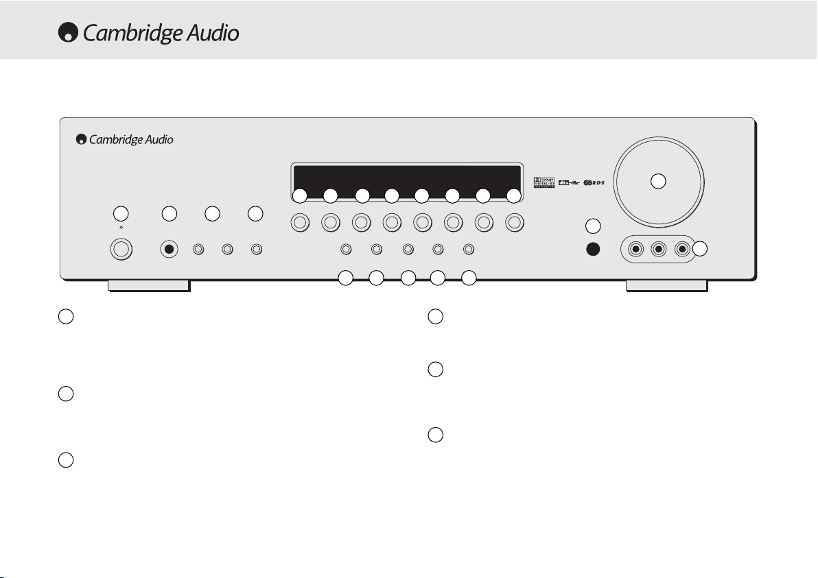
Standby/On
Switches the unit between Standby mode (indicated by dim power LED)
and On (indicated by bright power LED). Standby is a low power mode
where the power consumption is less than 10 Watts. The unit should be
left in Standby mode when not in use.
Phones
Allows for the connection of stereo headphones with a ¼" Jack plug.
Headphones with an impedance of between 32 and 600 ohms are
recommended.
Tuning ++/-
Used to tune FM frequencies and skip presets in Tuner mode.
Mode/Store
Press to cycle between Tuner modes (refer to the ‘Operating
Instructions’ of this manual for more information).
Stereo
Press to listen to a source in either analog stereo or digital (LPCM)
stereo (depending on the input mode) from the front left and right
loudspeakers only.
Dolby DDigital EEX // DDTS EES
Press to select between various standard Dolby Digital or DTS surround
5.1 modes (with suitably encoded digital source material). Also selects
extended Dolby Digital EX and DTS ES modes which provide 6.1 output
with suitably encoded EX/ES material. These modes can only be
decoded from digital audio sources (via Coaxial or Optical inputs). An
Autodetect mode is also available which allows the 540R V2.0 to
automatically set itself to the appropriate mode for digital material.
Volume
Phones Tuning Mode/Store
DVD Video 1
Dolby Digital EX/
DTS ES
DSP
Mode
Pro Logic II/
Neo 6
Input
Mode
Video 3 inputs
Video Left Right
Stereo
Video 2 Video 3 Tuner FM/AM Tape/MD/CDR CD/Aux 6.1 Direct
–+
Standby / On
azur 540R
AV Receiver
FRONT PANEL CONTROLS
1
2
3
5
1 2 3 4
5 6 7 8 9
10 11 12 13 14 15 16 17
18
19
20
4
6
Page 9

540R V2.0 AV receiver
Azur AV receiver 9
Pro LLogic III // NNeo:6
Press to decode suitable encoded analog stereo source material into
surround sound. Autodetection for these modes is not possible and they
must be manually selected.
DSP MMode
The 540R V2.0 can create a surround sound effect even from nonencoded material by Digital Signal Processing (DSP). Press this button to
choose one of the following surround sound effects: THEATER, HALL,
MOVIE, MUSIC or ROOM.
Input MMode
Press this button to toggle between analog or optical/coaxial digital
input types for the currently selected source. The 540R V2.0 remembers
the input type selected for each source when you return to that source.
DVD
Press to select the DVD source equipment for output through the 540R
V2.0.
Video 11
Press to select the source equipment connected to Video 1 for output
through the 540R V2.0.
Video 22
Press to select the source equipment connected to Video 2 for output
through the 540R V2.0.
Video 33
Press to select the source equipment connected to Video 3 (on the front
panel) for output through the 540R V2.0.
Tuner FFM/AM
Press to select the tuner for output through the 540R V2.0. In Tuner
mode also use this button to switch between FM and AM modes.
Tape/MD/CDR
Press to select the recording device connected to the Tape/MD/CDR
input for output through the 540R V2.0.
CD/Aux
Press to select the CD or other source equipment connected to CD/Aux
on the rear panel for output through the 540R V2.0.
6.1 DDirect
Press to select a 5.1 or 6.1 DVD-A or SACD player connected to the 6.1
Direct In sockets.
Infrared ssensor
Receives IR commands from the supplied Azur remote control. A clear
unobstructed line of sight between the remote control and the sensor is
required.
Volume
Use to increase/decrease the level of the sound from the outputs of the
540R V2.0.
Video 33 iinput ssockets
Allows a video camera recorder/video games console to be connected
and selected by the Video 3 source button.
7
8
10
9
11
15
16
17
18
19
12
13
14
20
Page 10
10 Azur AV receiver
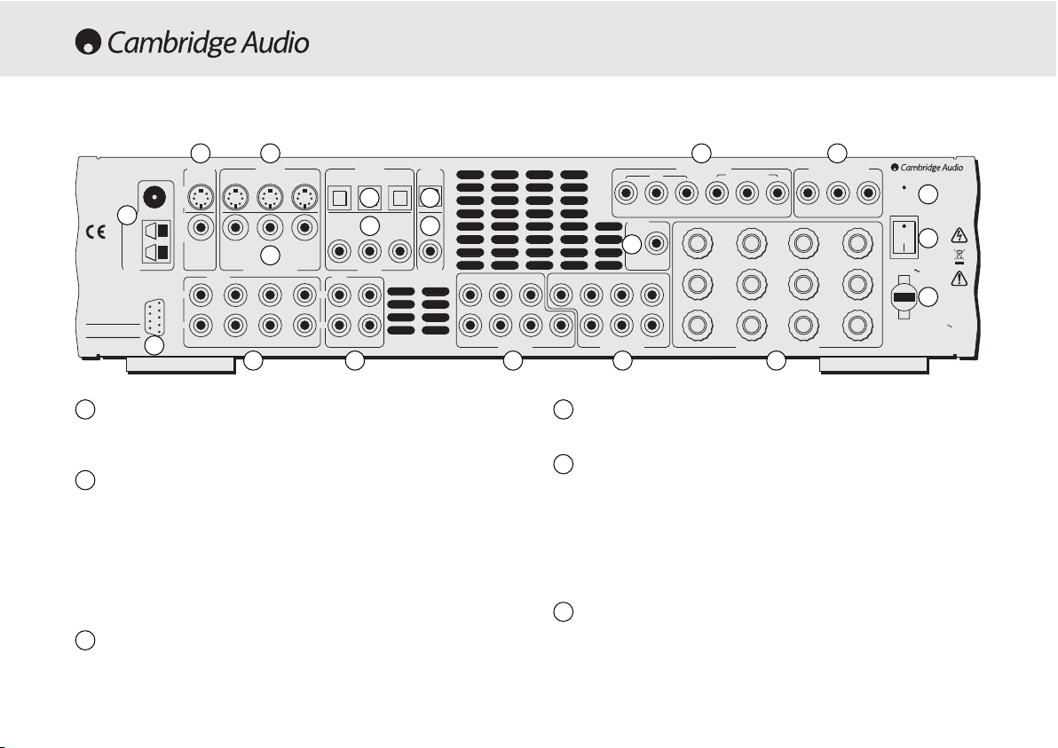
FM/AM aantenna
All tuner antenna connections are made here. Refer to the ‘Antenna
Connections’ section of this manual for more information.
TV/Mon ooutputs
S-Video - Connect to your television via S-Video cable to display the
picture of any S-Video connected unit.
Composite - Connect to your television via RCA phono cable to display
the picture of any composite video connected unit.
These outputs are also used to view the 540R V2.0’s on-screen setup
menu.
S-VVideo iinputs
Connect the S-Video outputs from the source equipment.
Composite VVideo iinputs
Connect the Composite Video outputs from the source equipment.
Component VVideo iinputs
Connect the Component Video outputs from the source equipment.
Note:
The preferred connection method for video sources is always
Component Video (highest quality) then S-Video then Composite Video.
DVD Component Video sources often also support Progressive Scan
which gives better picture quality if supported by both your DVD player
and TV.
Component VVideo OOut
Connect to the Cr/Pr, Cb/Pb, & Y terminals of a television set.
Note:
There is no on-screen setup menu present on the Component
Video outputs.
REAR PANEL CONNECTIONS
1
1
2 3
4
7
9
8
10
11
5 6
12
13
14
151617
1819
20
2
3
4
5
6
FM 75Ω
TV/Mon Out
S-VideoComposite
L
R
RS232C
CD/Aux
S-Video In
Video 2 Video 1 DVD CD Video 1/Video 2 DVD
Video 2 Video 1 DVD
Composite Video In
Audio In
Video 2 Video 1 DVD
Optical In
CD DVD
Video 1/Video 2
Coax InCoax In Coax Out
Tape
L
R
Tape Play Tape Rec
Optical
Out
RR
azur 540R V2.0
AV Receiver
Loop
300Ω
This device
complies with
part 15 of
FCC rules
Tuner
Manufactured
in an ISO9002
approved facility
Caution / Avis /Achtung
Risk of electric shock
Do not open
Risque de choc electrique
Ne pas ouvrir
Vorm öffnen des gërates
Netzstecker ziehen
AM
Component Video In
DVD
Cr/Pr Cb/Pb Y Cr/Pr Cb/Pb Y Cr/Pr Cb/Pb Y
Control
Bus
SL SLLL
SR SR
6.1 Direct In
SB
Cen C
SB
SW SW
In
6.1 Preamp Out
Video 1/Video 2
Sur
Left
Sur
Right
Sur
Back
Speaker Impedance 4-8 Ohms
Component Video Out
Right
Centre
Designed in London, England
www.cambridge-audio.com
Reset
On
Power
Power AC
Off
Left
Power Rating: 230V AC 50Hz
Max Power Consumption: 615W
Serial No. label fitted on underside
Page 11

540R V2.0 AV receiver
Azur AV receiver 11
Optical IIn
Connect to the digital optical (Toslink) outputs from source equipment.
Optical OOut
Connect to the digital optical (Toslink) input of an external recording
device (eg MD/CDR etc) to record from the selected digital audio source.
Coax IIn
Connect to the digital coaxial (SPDIF) outputs from source equipment.
Coax OOut
Connect to the digital coaxial (SPDIF) input of an external recording
device (eg MD/CDR etc) to record from the selected digital audio source.
Control BBus IIn
Allows un-modulated commands from multi-room systems or other
components to be received by the 540R V2.0.
Reset
Resets all factory default settings. Refer to the ‘Reset/Back-up memory’
section of this manual for more information.
Power OOn/Off
Switches the unit on and off.
Mains ppower llead
Once you have completed all connections, plug the AC power lead into
an appropriate mains socket. The AV receiver is now ready for use.
Speaker tterminals
Connect to loudspeakers with an impedance of between 4-8 ohms.
6.1 PPreamp OOut
Connect to the 6.1 (or 5.1) channel input terminals of another amplifier
system, separate power amps, subwoofer or active loudspeakers.
6.1 DDirect IIn
Connect to the 6.1 (or 5.1) channel output terminals of a DVD player
with built-in surround sound decoding for playing DVD-A or SACD.
Tape
Connect the Tape Play sockets to the line output terminals of a Tape
deck, MD player, CD-R etc. Connect the Tape Rec sockets to the line
input terminals of a Tape deck, MD player, CD-R etc.
Audio iinputs
Connect to the audio line output terminals of a source device (eg CD,
DVD player etc).
RS232C
For use by an installer/dealer for software updates.
7
14
15
16
17
18
19
20
8
9
10
11
12
13
Page 12
CH SSelect
Press to select individual channels, then use volume to balance
speakers.
Sub OOn/Off
Press to turn on/off the output of the subwoofer.
Delay
Press to set the delay times when setting up surround sound
speakers.
SPK SSetup
Press to change the surround sound speaker settings.
On-sscreen DDisplay ((OSD)
Press to access an on-screen set-up menu when connected to a
monitor/screen via composite or S-video connections.
Mute
Mutes the audio on the AV Receiver. The mute mode is indicated
by the channel LED flashing. Press again to cancel mute.
Volume
Increase or decrease the volume of the AV receiver output. Also
used as up/down in the OSD setup menu.
12 Azur AV receiver
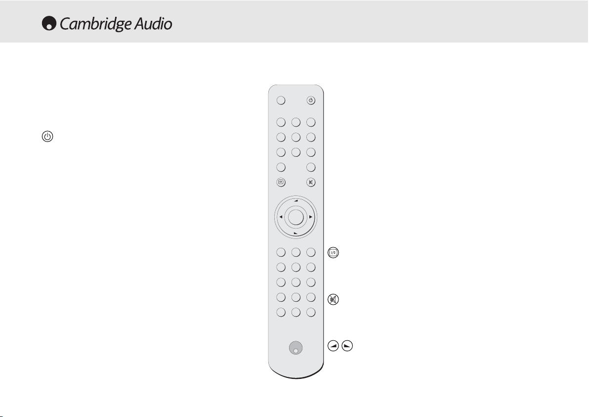
REMOTE CONTROL
The 540R V2.0 is supplied with an Azur Navigator remote control.
Insert the supplied AAA batteries to activate. For full details of the
various adjustment functions available from the remote, refer to
the later sections of this manual.
Standby/On
Switches the unit between On and Standby mode.
Input MMode
Switches the 540R V2.0 between analog and digital inputs for the
currently selected source.
Stereo, PLII/NEO 66, DDD EEX/DTS EES, DDSP MMode
See button details as listed in the ‘Front Panel Controls’ section.
Dynamic
Press repeatedly to reach the desired dynamic compression range
(Dolby Digital mode only).
LFE TTrim
Press to access the Low Frequency Trim (subwoofer) mode.
Test TTone
Press to access the test tones to balance your surround sound
speakers.
Stereo
Input
Mode
6.1
Direct
DSP
Mode
Dynamic
PL II
Neo 6
DD EX
DTS ES
Test
ToneCHSelect
LFE
Trim
Sub
On/Off
Delay
Tuner
AM/FM
Bass
Treble
ModeStore
Stereo
Mono
DisplayPTY APS
SPK
Setup
DVD Video 1 Video 2
Video 3
CD
Aux
Tape
MD/CDR
Enter
Vol
Vol
Page 13

Tune
Press the right arrow to increase tuner frequency/change preset. Press
the left arrow to decrease tuner frequency/change preset. Also used to
scroll left/right in the OSD setup menu.
Enter
Used in the OSD setup menu.
6.1 DDirect
Selects the 5.1/6.1 Direct input.
Bass TTreble
Press for bass/treble adjustment, using the Volume up/down buttons.
PTY ((Program TType SSearch)
Press to search by program type when in Tuner mode.
APS ((Auto PProgram SSearch)
Allocates and memorises radio stations automatically.
Display
When listening to source equipment press to view the input type
(optical/coaxial or analog). When listening to FM with RDS, press to view
station information.
540R V2.0 AV receiver
Azur AV receiver 13
Stereo MMono
When listening to FM, press to alternate between stereo and mono
modes.
Store
Press to store the current frequency when in Tuner mode.
Mode
Press to select Auto/Manual or Preset tuning when in Tuner mode.
Tuner FFM/AM, DDVD, VVideo 11, VVideo 22, VVideo 33, TTape
MD/CDR, CCD AAux
Press the corresponding button to change the input source. Pressing the
Tuner AM/FM button a second time toggles between FM and AM modes.
Please rrefer tto tthe ‘‘Operating IInstructions’ ssection oof tthis
manual ffor mmore iinformation oon ssome ffunct
ions oof tthese
buttons.
Page 14

14 Azur AV receiver
The 540R V2.0 has several music and home-cinema listening modes
available, all designed to reproduce “surround sound” effects,
dependant on the input signal and speaker setup:
Stereo
Only the Front Left and Front Right speakers (and subwoofer if selected)
have output in this mode. If an analog source is selected you will be
listening to pure analog stereo with no digital signal processing. If a
digital source is selected the 540R V2.0 will act as a digital to analog
converter and play back stereo LPCM as output by CD players etc.
Dolby DDigital ((5.1)
Provides (up to) 5.1 output from suitable encoded Dolby Digital material
using 5 main speakers (Left Front , Right Front , Centre, Left Surround,
Right Surround) and a subwoofer. Decoding Dolby Digital requires a
Dolby Digital encoded DVD disc and a digital connection from the 540R
V2.0 to the source equipment (Such as a DVD player).
DTS ((5.1)
DTS also provides (up to) 5.1 output from suitable encoded DTS material
using 5 main speakers (Left front , Right front , Centre, Left Surround,
Right Surround) and a subwoofer. Decoding DTS requires a suitably
encoded DTS disc and a digital connection from the 540R V2.0 to the
source equipment.
Dolby DDigital EEX ((6.1)
An enhanced form of Dolby Digital, DD EX provides an extra channel
(Surround Back) for greater image depth and more solid sound
localisation behind the listener. DD EX requires a DD EX encoded disc.
DTS-EES DDiscrete ((6.1)
An enhanced form of DTS, ES provides an extra channel (Surround Back)
SURROUND SOUND MODES
for greater image depth and more solid sound localisation behind the
listener. All channels are discretely encoded digitally for the best
possible surround sound effect. DTS-ES Discrete requires a DTS-ES
Discrete encoded disc.
DTS-EES MMatrix ((6.1)
Another enhanced form of DTS, ES Matrix also provides an extra channel
(Surround Back) but instead the extra channel is inserted into the left
and right surround channels in a matrix process. DTS-ES Matrix requires
a DTS-ES Matrix encoded disc.
Pro LLogic III
A newer version of Dolby Pro Logic which is able to recreate 5.1 surround
sound from suitable encoded analog source material. The source
material is stereo (and can be played as such) but also has special
encoding that allows the 540R V2.0 to decode a 5.1 surround sound
output. There are 5 standard modes: Movie, Music, Virtual, Pro Logic
Emulation and Matrix.
DTS NNeo:6
A DTS technology which is able to recreate 6.1 surround sound from
suitable encoded analog source material. The source material is stereo
(and can be played as such) but also has special encoding that allows
the 540R V2.0 to decode a 6.1 surround sound output. There are 2
standard modes: Cinema and Music.
DSP mmodes
These modes allow a realistic surround-sound experience from source
material that has no encoding at all. The surround sound effect is
achieved by Digital Signal Processing of the Analog or Digital stereo
source used. Five modes are possible: Theater, Hall, Movie, Music and
Room.
Page 15
540R V2.0 AV receiver
Azur AV receiver 15
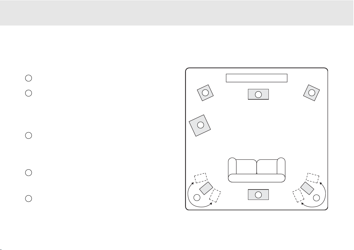
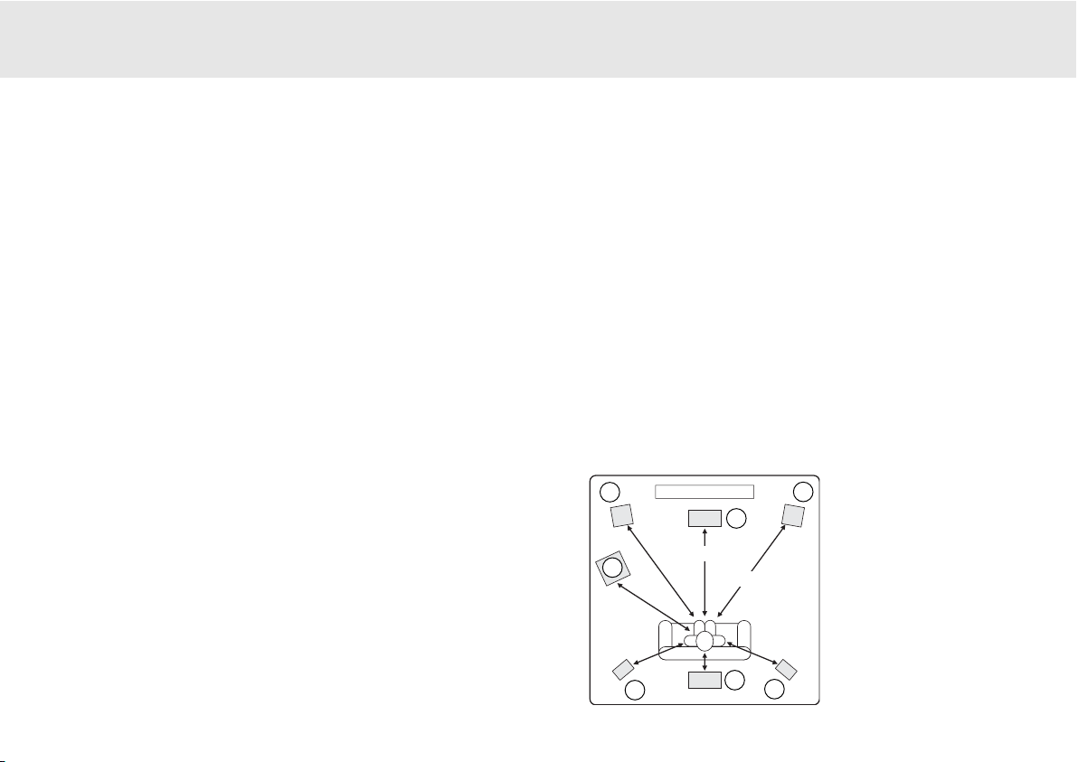
The diagram shows a typical example of a 5.1/6.1 loudspeaker setup.
Always adjust the speaker and listening positions until you are happy
with the sound. Please refer to the loudspeaker and subwoofer manuals
for more detailed positioning information.
Front LLeft aand RRight sspeakers
-
For stereo and multi-channel sound.
Angle towards the listening position.
Centre sspeaker
-
For dialogue and centre sounds. Position at a
similar height to the front left and right speakers (above or below the
TV/monitor). Using a centre speaker from the same
manufacturer/range as used used for the front left and right speakers
is advisable. This “timbre matching” allows surround effects to flow
more naturally from left to right without obvious transitions between the
speakers.
Surround LLeft aand RRight sspeakers
-
For ambient and multi-channel
sound. Floorstanding speakers should be angled towards the listening
position. Bookshelf/standmount speakers should be wall mounted or
used with dedicated speaker stands, positioned at or above ear height.
To set the required delay between speakers for surround sound modes,
please refer to the ‘Surround Sound Setup’ section of this manual.
Surround BBack sspeaker
-
Optional sixth channel speaker, required
for enjoying Dolby®Digital EX or DTS®-ES audio. Improves the quality of
sound effects by filling the gap between the surround left and rear right
speakers. Position the speaker firing towards the front of the room.
Subwoofer
- For improving the bass in your system, as well as
reproducing LFE cinema effects when playing Dolby Digital or DTS
encoded discs. Your subwoofer can often be placed almost anywhere in
the room as bass is less directional, but experimentation with
positioning is recommended.
LOUDSPEAKER POSITIONING
1
2
3
5
4
55..11//66..11
1 1
2
4
3
3
5
**
* Optional “6th” speaker
Page 16
16 Azur AV receiver
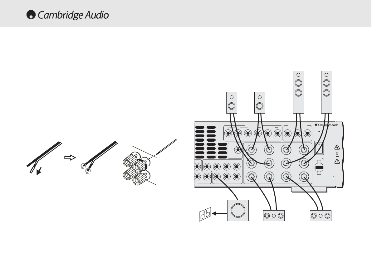
To avoid damaging the speakers with a sudden high-level signal, be sure
to switch the power off before connecting the speakers. Check the
impedance of your speakers. Speakers with an impedance of between
4 and 8 ohms (each) are recommended.
The coloured speaker terminals are positive (+) and the black speaker
terminals are negative (-). Make sure correct polarity is maintained at
each speaker connector or the sound can become weak and “phasey”
with little bass.
Prepare the speaker cords for connection by stripping off approximately
10mm (3/8”) or less (no more than 10mm, as this could cause a shortcircuit) of the outer insulation. Twist the wire tightly together so there are
no loose ends. Unscrew the speaker terminal knob, insert the speaker
cable, tighten the knob and secure the cable.
Note:
All connections are made via loudspeaker cable, except if using an
active subwoofer which would be connected via a standard RCA phono
cable. Banana Plugs (4mm standard) connected to the speaker cable
are recommended for direct insertion into the speaker terminals.
LOUDSPEAKER CONNECTIONS
Power Rating: 230V AC 50Hz
Sur
Left
Sur
Right
Sur
Back
Left
Right
Centre
Reset
Power
On
Off
SB
SB
SW SW
Cen C
SR
R
SL L
Power AC
Max Power Consumption: 615W
t In
6.1 Preamp Out
Cr/Pr Cb/Pb Y Cr/Pr Cb/Pb Y Cr/Pr Cb/Pb Y
Component Video In
DVD
Video 1/Video 2
Component Video Out
www.cambridge-audio.com
Designed in London, England
Speaker Impedance 4-8 Ohms
Control
Bus
Serial No. label fitted on underside
In
FFrroonntt rriigghhtt
ssppeeaakkeerr
FFrroonntt lleefftt
ssppeeaakkeerr
SSuurrrroouunndd
lleefftt ssppeeaakkeerr
SSuurrrroouunndd
rriigghhtt ssppeeaakkeerr
FFrroonntt cceennttrre
e
ssppeeaakkeerr
SSuurrrroouunndd bbaacckk
ssppeeaakkeerr
PPoowweerreedd
ssuubbwwooooffeerr
PPhhoonnoo//RRCCAA ccaabbllee
Page 17
540R V2.0 AV receiver
Azur AV receiver 17
VIDEO CONNECTIONS
AUDIO CONNECTIONS
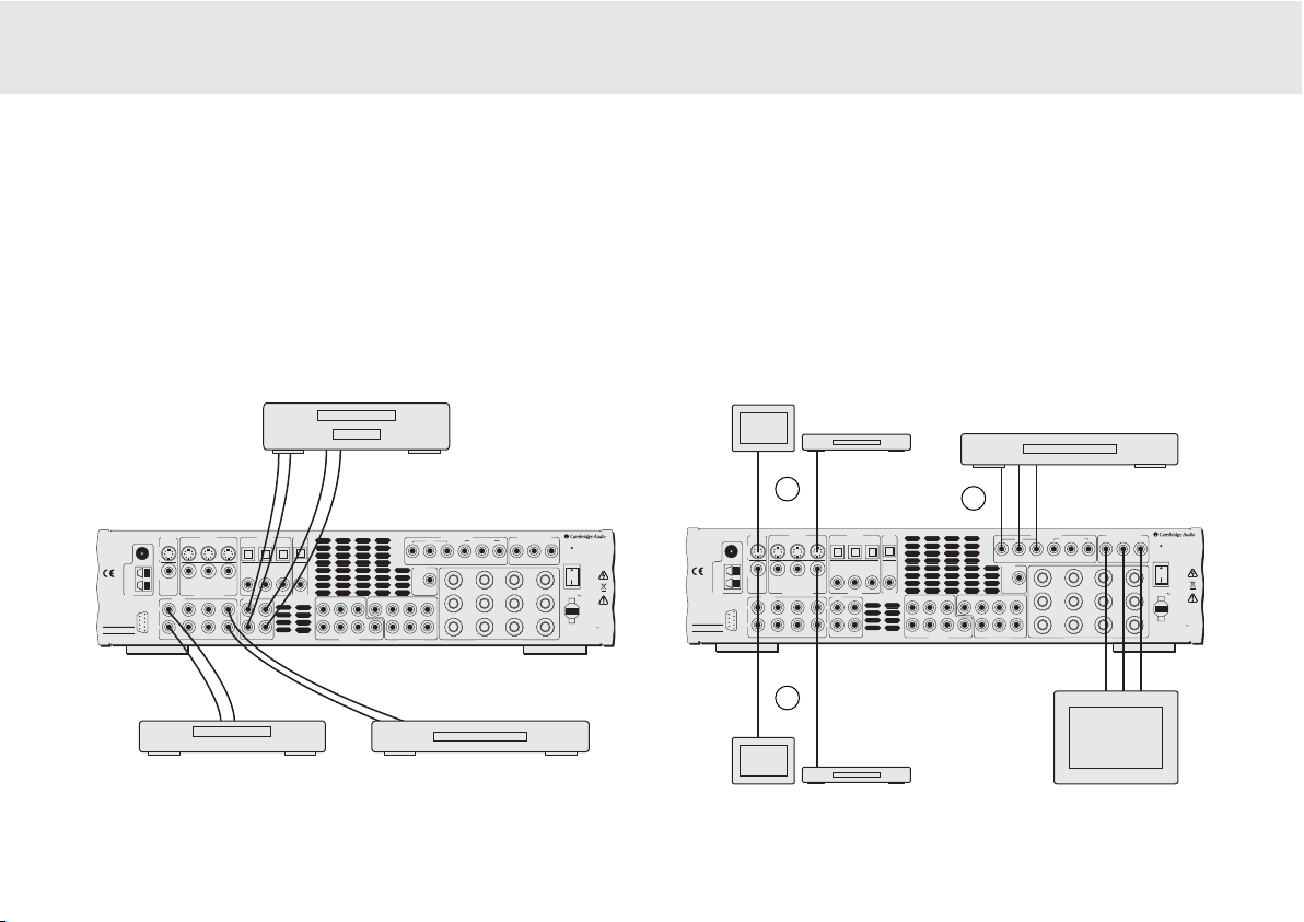
Note:
Do not plug in the mains power lead or turn the unit on until all
connections have been made.
Connect to source equipment using stereo phono cables (stereo 2RCA2RCA). Tape/MD/CDR recorder/players require two sets of stereo
phono/RCA cables, one for recording, one for listening.
Three types of video connections can be made on the 540R V2.0:
Composite (1), S-Video (2) and Component (3). For best picture quality
we recommend making Component video connections, then in declining
order of quality, S-Video connections and then Composite video
connections. The 540R V2.0 does not provide conversion between
Composite, S-Video or Component video formats (e.g. if you are
watching a S-Video input from a DVD, you must view it from the S-Video
output on the 540R V2.0).
CCDD ppllaayyeerr DDVVDD ppllaayyeerr
TTaappee ppllaayyeerr//rreeccoorrddeerr
CCoommppoonneenntt ccaabbllee
((33RRCCAA-33RRCCAA))
SS-VViiddeeoo
ccaabbllee
SSiinnggllee 7755 oohhmm
PPhho
onnoo ccaabbllee
((RRCCAA-RRCCAA))
DDVVDD ppllaayyeerr
TTVV//MMoonniittoorr
CCoommppoonneenntt ccaabbllee
((33RRCCAA-33RRCCAA))
2
1
3
DDVVDD ppllaayyeerr
TTVV//MMoonniittoorr
DDVVDD ppllaayyeerr
TTVV//MMoonniittoorr
PPhhoonnoo ccaabbllee ((22RRCCAA-22RRCCAA))
PPhhoonnoo ccaabbllee ((22RRCCAA-22RRCCAA))
azur 540R V2.0
AV Receiver
This device
complies with
part 15 of
FCC rules
Manufactured
in an ISO9002
approved facility
Caution / Avis /Achtung
Risk of electric shock
Do not open
Risque de choc electrique
Ne pas ouvrir
Vorm öffnen des gërates
Netzstecker ziehen
FM 75Ω
AM
Loop
300Ω
Tuner
TV/Mon Out
Video 2 Video 1 DVD CD Video 1/Video 2 DVD
S-VideoComposite
Video 2 Video 1 DVD
Composite Video In
Audio In
L
R
RS232C
Video 2 Video 1 DVD
CD/Aux
CD DVD
Tape
L
R
Tape Play Tape Rec
Video 1/Video 2
Coax InCoax In Coax Out
Out
SL SLLL
RR
SR SR
6.1 Direct In
Cr/Pr Cb/Pb Y Cr/Pr Cb/Pb Y Cr/Pr Cb/Pb Y
SB
Cen C
SB
SW SW
6.1 Preamp Out
Optical
Optical In
S-Video In
Component Video In
DVD
Control
Bus
In
Video 1/Video 2
Sur
Left
Sur
Right
Sur
Back
Speaker Impedance 4-8 Ohms
Component Video Out
Left
Right
Centre
Designed in London, England
www.cambridge-audio.com
Reset
On
Power
Off
Power AC
Power Rating: 230V AC 50Hz
Max Power Consumption: 615W
Serial No. label fitted on underside
azur 540R V2.0
AV Receiver
This device
complies with
part 15 of
FCC rules
Manufactured
in an ISO9002
approved facility
Caution / Avis /Achtung
Risk of electric shock
Do not open
Risque de choc electrique
Ne pas ouvrir
Vorm öffnen des gërates
Netzstecker ziehen
TV/Mon Out
S-VideoComposite
FM 75Ω
AM
Loop
300Ω
Tuner
L
R
RS232C
CD/Aux
S-Video In
Video 2 Video 1 DVD CD Video 1/Video 2 DVD
CD DVD
Video 2 Video 1 DVD
Composite Video In
Audio In
Video 2 Video 1 DVD
Tape
L
R
Tape Play Tape Rec
Optical In
Optical
Video 1/Video 2
Coax InCoax In Coax Out
Out
SB
SL SLLL
Cen C
SB
RR
SW SW
SR SR
6.1 Direct In
Component Video In
Video 1/Video 2
DVD
Cr/Pr Cb/Pb Y Cr/Pr Cb/Pb Y Cr/Pr Cb/Pb Y
Control
Bus
Sur
Left
In
Sur
Right
Sur
6.1 Preamp Out
Back
Speaker Impedance 4-8 Ohms
Component Video Out
Left
Right
Centre
Designed in London, England
www.cambridge-audio.com
Reset
On
Power
Off
Power AC
Power Rating: 230V AC 50Hz
Max Power Consumption: 615W
Serial No. label fitted on underside
Page 18
18 Azur AV receiver
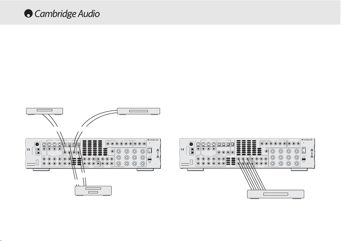
DIGITAL CONNECTIONS
Two types of digital audio connections can be made to the 540R V2.0,
Optical/Toslink and Coaxial/SPDIF. Either type can be used for each
source as the 540R V2.0 is able to convert between the two. Only one
connection type should be used per source.
Whichever type is used to connect to the digital inputs, both the
coaxial/SPDIF and optical/toslink outputs on the 540R V2.0 will be active.
OOppttiiccaall ccaabbllee
((OOPPTT-OOPPTT))
DDVVDD ppllaayyeerrCCDD ppllaayyeerr
MMDD//DDVVDD-RR//CCDD-RR
6.1 DIRECT IN
To listen to multi-channel DVD Audio player or SACD discs connect your
DVD/SACD player to the 6.1 Direct In sockets.
As any signals connected to the 6.1 Direct Input (multi-channel DVD-A /
SACD etc.) will have been decoded by an external unit it may be necessary
to adjust the relative levels of each channel when listening to this input.
This can be done using the CH Select button on the remote, the 540R
V2.0’s front panel display will rotate round each channel in turn.
Use Volume up/down on the remote to adjust the relative level of each
input channel in turn by -10dB to +10dB in 1dB steps. If no adjustment
is made for 5 seconds the unit saves the settings and returns to its
normal state. Note that any changes made are saved and will affect all
surround sound modes.
DDVVDD-AA ppllaayyeerr oorr SSAACCDD mmuullttii-cchhaannnneell
ppllaayyeerr 55..11 oorr 66..11 ccoonnnneeccttiioonnss
OORR
OORR
OORR
OORR
PPhhoonnoo ccaabbllee ((22RRCCAA-22RRCCAA))
Component Video In
Video 1/Video 2
DVD
Cr/Pr Cb/Pb Y Cr/Pr Cb/Pb Y Cr/Pr Cb/Pb Y
Control
Bus
Sur
Left
In
SB
SL SLLL
Cen C
SB
RR
SW SW
SR SR
6.1 Direct In
6.1 Preamp Out
Sur
Right
Sur
Back
Speaker Impedance 4-8 Ohms
Component Video Out
Left
Right
Centre
Designed in London, England
www.cambridge-audio.com
Reset
On
Power
Off
Power AC
Power Rating: 230V AC 50Hz
Max Power Consumption: 615W
Serial No. label fitted on underside
azur 540R V2.0
AV Receiver
This device
complies with
part 15 of
FCC rules
Manufactured
in an ISO9002
approved facility
Caution / Avis /Achtung
Risk of electric shock
Do not open
Risque de choc electrique
Ne pas ouvrir
Vorm öffnen des gërates
Netzstecker ziehen
FM 75Ω
AM
Loop
300Ω
Tuner
S-Video In
TV/Mon Out
Video 2 Video 1 DVD CD Video 1/Video 2 DVD
S-VideoComposite
Video 2 Video 1 DVD
Composite Video In
Audio In
L
R
RS232C
Video 2 Video 1 DVD
CD/Aux
CD DVD
Tape
L
R
Tape Play Tape Rec
Optical In
Video 1/Video 2
Coax InCoax In Coax Out
Optical
Out
azur 540R V2.0
AV Receiver
This device
complies with
part 15 of
FCC rules
Manufactured
in an ISO9002
approved facility
Caution / Avis /Achtung
Risk of electric shock
Do not open
Risque de choc electrique
Ne pas ouvrir
Vorm öffnen des gërates
Netzstecker ziehen
FM 75Ω
AM
Loop
300Ω
Tuner
RS232C
TV/Mon Out
Video 2 Video 1 DVD CD Video 1/Video 2 DVD
S-VideoComposite
Video 2 Video 1 DVD
Audio In
L
R
Video 2 Video 1 DVD
CD/Aux
S-Video In
Composite Video In
CD DVD
Tape
L
R
Tape Play Tape Rec
Optical In
Video 1/Video 2
Coax InCoax In Coax Out
Optical
Out
Component Video In
DVD
Cr/Pr Cb/Pb Y Cr/Pr Cb/Pb Y Cr/Pr Cb/Pb Y
Control
Bus
In
SB
SL SLLL
Cen C
SB
RR
SW SW
SR SR
6.1 Direct In
6.1 Preamp Out
Video 1/Video 2
Sur
Left
Sur
Right
Sur
Back
Speaker Impedance 4-8 Ohms
Component Video Out
Left
Right
Centre
Designed in London, England
www.cambridge-audio.com
Reset
On
Power
Off
Power AC
Power Rating: 230V AC 50Hz
Max Power Consumption: 615W
Serial No. label fitted on underside
Page 19
540R V2.0 AV receiver
Azur AV receiver 19
PPoowweerr aammpplliiffiieerr
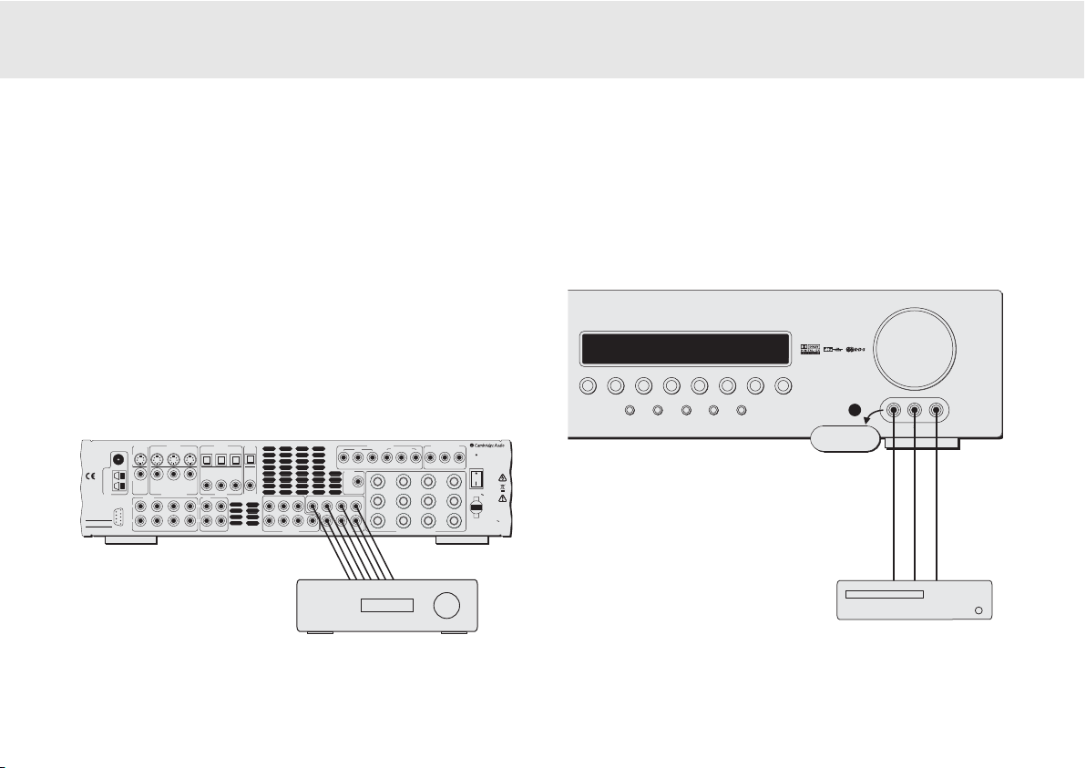
6.1 PREAMP OUT
To connect external power amplifiers, use Phono/RCA leads connected
to the 6.1 Preamp Outputs on the rear panel.
Set the Pre Out setting in the Output Setup OSD menu to 'Pre Out' rather
than 'Normal'. This mutes the internal power amplifiers as they are not
being used.
PPhhoonnoo ccaabbllee ((22RRCCAA-22RRCCAA))
FRONT INPUT CONNECTIONS
Volume
DVD Video 1
Dolby Digital EX/
DTS ES
DSP
Mode
Pro Logic II/
Neo 6
Input
Mode
Video 3 inputs
Video Left Right
Stereo
Video 2 Video 3 Tuner FM/AM Tape/MD/CDR CD/Aux 6.1 Direct
azur 540R
AV Receiver
VViiddeeoo ggaammeess ccoonnssoollee
((oorr vviiddeeoo ccaammeerraa rreeccoorrddeerr))
The front panel Video 3 input is for temporary connections to video
games consoles etc. Remove the cap to access the Video 3 inputs, and
connect to a video game or video camera’s outputs using a composite
video cable and stereo phono cable (RCA-RCA).
CCoommppoossiittee
vviiddeeoo
ccaabbllee
SStteerreeoo
pphhoonnoo
ccaabbllee
((RRCCAA-RRCCAA))
azur 540R V2.0
AV Receiver
This device
complies with
part 15 of
FCC rules
Manufactured
in an ISO9002
approved facility
Caution / Avis /Achtung
Risk of electric shock
Do not open
Risque de choc electrique
Ne pas ouvrir
Vorm öffnen des gërates
Netzstecker ziehen
Loop
300Ω
Tuner
AM
FM 75Ω
S-Video In
TV/Mon Out
Video 2 Video 1 DVD CD Video 1/Video 2 DVD
S-VideoComposite
Video 2 Video 1 DVD
Composite Video In
Audio In
L
R
RS232C
CD/Aux
L
R
Video 2 Video 1 DVD
Optical In
Optical
Out
Video 1/Video 2
CD DVD
Coax InCoax In Coax Out
Tape
Tape Play Tape Rec
RR
Component Video In
Video 1/Video 2
DVD
Cr/Pr Cb/Pb Y Cr/Pr Cb/Pb Y Cr/Pr Cb/Pb Y
Control
Bus
Sur
Left
In
SB
SL SLLL
Cen C
SB
SW SW
SR SR
6.1 Direct In
6.1 Preamp Out
Sur
Right
Sur
Back
Speaker Impedance 4-8 Ohms
Component Video Out
Left
Right
Centre
Designed in London, England
www.cambridge-audio.com
Reset
On
Power
Off
Power AC
Power Rating: 230V AC 50Hz
Max Power Consumption: 615W
Serial No. label fitted on underside
Page 20
20 Azur AV receiver
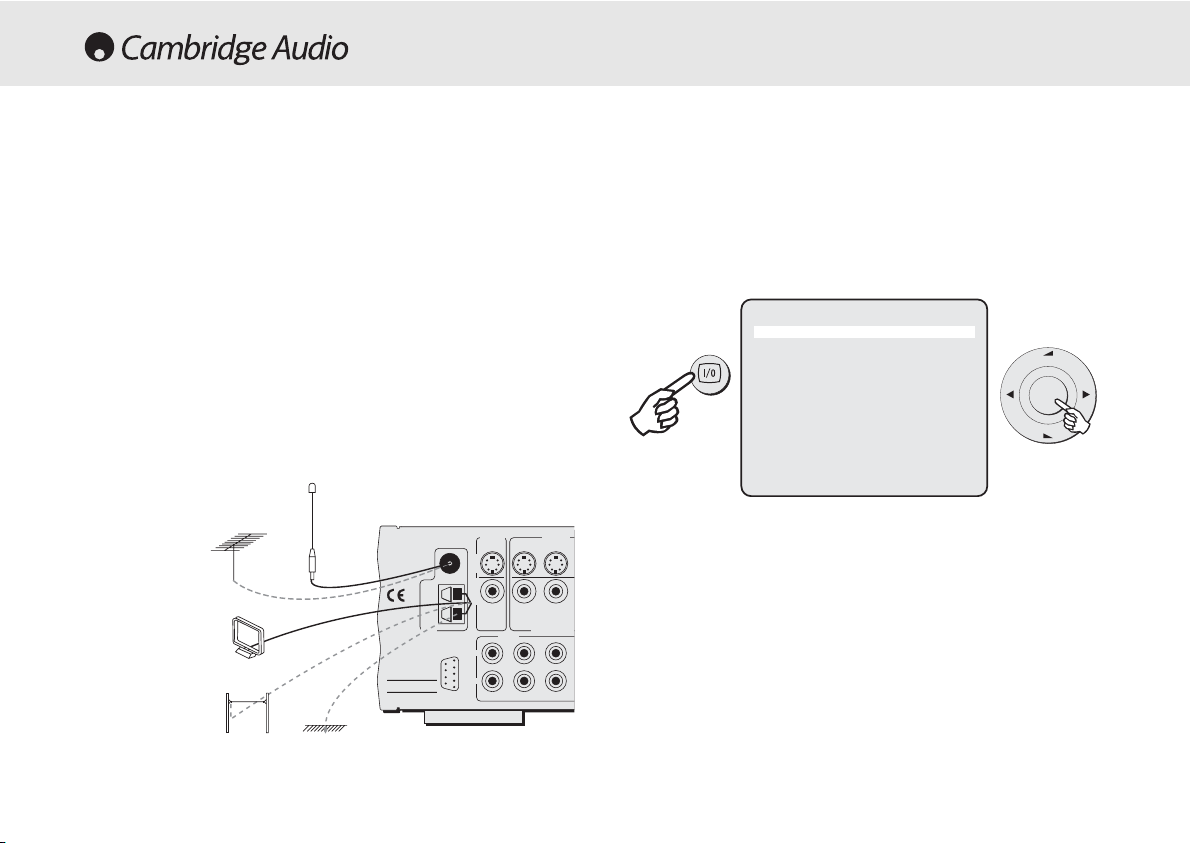
FM aaerial
Connect an aerial to the FM 75 ohm socket (a simple wire aerial is
supplied for temporary use). Extend the lead and move the aerial around
until you get the best reception. For continued use, we strongly
recommended using a 75ohm outdoor FM aerial.
AM lloop aaerial
Connect each end of the single length antenna to the antenna
terminals. Place the antenna as far from the main system as possible to
prevent unwanted noise and to obtain optimum reception. If the AM loop
aerial provided does not receive sufficient reception, it may be
necessary to use an outdoor AM aerial.
AERIAL CONNECTIONS
FM 75Ω
AM
Loop
300Ω
Video 2 Video 1CD/Aux
Video 2 Video 1
Video 2 Video 1
Tuner
RS232C
S-Video In
Composite Video
Audio In
L
R
Risk of electric shock
Do not open
Caution / Avis /Achtung
Risque de choc electrique
Ne pas ouvrir
Vorm öffnen des gërates
Netzstecker ziehen
This device
complies with
part 15 of
FCC rules
Manufactured
in an ISO9002
approved facility
TV/Mon Out
S-VideoComposite
azur 540R V2.0
AV Receiver
FFMM aaeerriiaall
FFMM eexxtteerrnnaall aaeerriiaall
AAMM eexxtteerrnnaall aaeerriiaall
AAMM lloooopp aaeerriiaall
OORR
OORR
GGrroouunndd
ON-SCREEN DISPLAY (OSD)
Once the 540R V2.0 is connected to all AV components, the system
setup can be completed either using the display on the front of the unit,
or if connected to a screen/monitor, via an on-screen display setup
menu (recommended). To access this menu, press the On-screen
Display button on the remote control.
To move around the OSD setup menu, simply use the Navigator controls
on the remote. Press the Arrow right/left to scroll through the menu
options, and Volume up/down to move up or down. Press the centre
Enter button to progress into a sub-menu. Press the OSD button to save
the settings and exit the setup menu.
Note: TThe OOSD ssetup mmenu iis oonly aavailable oon aa
screen/monitor cconnected vvia SS-VVideo oor CComposite iinpu
ts.
azur 540R V2.0 Menu
1. Speaker Config
2. Speaker Dealy
3. Level Calibration
4. Input Setup
5. Output Setup
6. Input Assign
7. OSD Setup
8. Bass/Treble Config
9. Sub Crossover
10. Software Version
(Quit OSD)
Vol
Enter
Vol
Page 21

540R V2.0 AV receiver
Azur AV receiver 21
Speaker CConfiguration
Assign the size of the speakers in your system (Small, Large or None if
not used).
Speaker DDelay
Set delay for your speakers according to their positions in your room.
This is calculated in milliseconds per metre. Please refer to the
‘Surround Sound Setup’ section of this manual for more information on
these speaker setup menus.
Level CCalibration
Select to send a test tone signal through individual speakers. Adjust the
output to obtain the best sound. Please refer to the ‘Surround Sound
Setup’ section of this manual for more information on these speaker
setup menus.
Input SSetup
Assign the audio source inputs to be digital or analog each time they are
selected. Video 3, Tuner, Tape, and 6.1 Direct will always be analog.
Output SSetup
If an external amplifier is connected via the 6.1 Preamp out sockets,
select ‘Preamp Out’ to mute the internal amplifiers.
Input AAssign
Assign the Component video and/or digital audio source inputs for Video
1/Video 2.
OSD SSetup
TV format - Choose PAL (UK/Europe) or NTSC (Canada/USA) depending
on your TV type.
Background - Choose a blue screen or video source as the background
image for the OSD setup menu.
OSD Video - If Video selected for the background, choose the video
source (Composite or S-Video).
Language - Scroll through the available languages for the OSD setup
menu and press the Enter button to select.
Bass/Treble CConfiguration
Increase/decrease the bass/treble tone control settings.
Sub CCrossover FFrequency
Set the frequency at which bass sounds are to be sent to the subwoofer
(range 40Hz - 200Hz).
Software VVersion
Displays the current loaded software version.
OSD MENUS
Page 22

22 Azur AV receiver
To setup the 540R V2.0 for surround sound use it is necessary to
perform 3 steps to match the unit to your speaker package type and
configuration. The required steps are:
1. Speaker Types - tell the 540R V2.0 how many and what type of
speakers are connected ('Large' or 'Small' in terms of bass response).
2. Delay Times - set up a delay time for the rear surround and/or centre
speakers so that the sound arrives at the listening position at the
right time (for each speaker) for the best surround sound effect.
3. Level Calibration - adjust the relative level of each speaker to take
into account any difference in efficiency or speaker type between
each speaker.
Optionally, when using the unit and after having performed the 3 stages
above you can then perform two other surround sound adjustments:
• Trimming the Low Frequency Effect (LFE) level to taste/circumstances.
• Applying Dynamic Range Control (DRC) to reduce the volume range of
loud to quiet passages in movie soundtracks.
These two extra adjustments can be made where it might be desired to
reduce the bass output level and/or the maximum difference in
loudness between quiet and loud passages in the movie. For example,
to change loudness temporarily for late night listening.
Step 11 - SSpeaker TTypes
The 540R V2.0 can support up to a 6.1 speaker setup which means 6
speakers (Front Left, Front Right, Centre, Surround Left, Surround Right,
Back Surround) plus a mains powered Subwoofer (the .1).
The first step is to tell the unit how many speakers you are actually
using. For example, if you choose not to use a Centre Channel speaker
you can set this to 'None' in the settings and the 540R V2.0 will
automatically redirect the centre channel audio information into the Left
and Right Front channels, creating what is know as a 'Phantom Centre'.
Similarly, you might decide to not use a subwoofer if your main Left and
Right speakers are capable of reproducing enough bass for a satisfying
music/movie experience.
Our advice would be a 5.1 or 6.1 setup to take full advantage of the
540R V2.0's capabilities and modern movie soundtracks. The
difference being whether it is chosen to use a Back Surround speaker.
This extra speaker is only required if it is desired to play back 6.1
material such as DD EX, DTS ES or Neo:6. All other material only requires
a 5.1 speaker package.
In addition each speaker that is being used can also be set to be either
'Large' or 'Small' (the 'Large' or 'Small' settings do not necessarily reflect
the actual physical size of the speaker):
Large -
speakers with an extended low frequency response of
approximately 20-30Hz to 16-20kHz (floorstanders or high quality larger
stand-mounted speakers).
Small -
speakers with a less extended low frequency response of
approximately 80-100Hz to 16-20kHz (small stand-mounted, bookshelf
or satellite speakers).
Setting each speaker allows the 540R V2.0 to perform Bass
Management and to direct low frequency bass from music and the Low
Frequency Effects channel of surround sound material to those
speakers best able to reproduce it. The process is fairly self explanatory
and can be achieved via the OSD Speaker Config Menu (recommended)
or via the front panel display by pressing SPK Setup on the remote.
SURROUND SOUND SETUP
Page 23
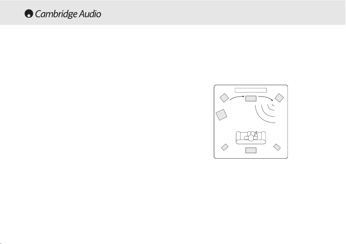
must be situated equidistant from the listener/viewer.
In addition Dolby Pro Logic II playback also requires an extra 15
milliseconds delay to the surround channels only (in addition to any
surround delay set above). This extra delay is part of the Dolby Prologic
II specification and ensures that sound from the surrounds arrives just
after sound from the front reducing the audibility of sound leakage from
the front to the surround speakers. This is necessary as Dolby Prologic
II being an analog encoding process does not possess the complete
channel separation of the DD or DTS Digital systems.
Because the relationship between the Dolby Digital and Dolby ProLogic
II two delays is fixed (15mS extra to the surround channels), it is only
necessary to set the delay in either one of the two modes. The 540R
V2.0 will automatically provide the appropriate delay whenever you
switch to the other mode.
To set the delay times simply measure the distances from the listening
position to the each speaker as shown in the following diagram:
540R V2.0 AV receiver
In the second case the 540R V2.0 displays each speaker type (FL/R
Large to indicate the Front Left and Right as ‘Large’ etc.) each time the
SPK Setup button is pushed. The settings are changed via Volume
up/down and once set wait for a few seconds for the 540R V2.0 to save
the settings and exit the menu.
Note:
The 540R V2.0 will force some speakers to certain settings in
some circumstances as below!
The Front Left and Right speakers may be ‘Large’ or ‘Small’ but never
‘None’ as they are always required for any type of music/movie
reproduction.
Bass must always be reproduced by either the Front Left and Right or
Subwoofer channel (or both). Setting the Front Left and Right to ‘Small’
will result in the Subwoofer automatically being set to ‘On’. Setting the
Subwoofer to ‘Off’ will automatically result in the Front Left and Right
being set to ‘Large’.
If the Front Left and Right cannot reproduce low frequency bass a
Subwoofer must be used. Also, setting the Front Left and Right as
‘Small’ will always set the other speakers as ‘Small’ (and the Sub to
‘On’). This is because LFE/ bass information should not be redirected to
the surround channels. With the caveats above, all other speakers can
be ‘Large’ or ‘Small’ or ‘None’.
Step 22 - DDelay TTimes
Because the speakers in a surround sound system are usually different
distances from the viewer/listener the 540R V2.0 incorporates the
ability to apply a variable digital delay to the each of the channels so that
the sound from each appears at the same time at the listening position
for best surround-sound effect. Each pair of speakers (i.e. Front Left and
Right or Surround Left and Right) are subject to the same delay and so
1
1
2
4
3
3
5
11 == FFrroonntt LLeefftt && RRiigghhtt
ssppeeaakkeerrss
22 == CCeennttrree ssppeeaakkeerr
33 == SSuurrrroouunndd LLeefftt && RRiigghhtt
ssppeeaakkeerrss
44 == SSuurrrroouunndd BB
aacckk ssppeeaakkeerr
55 == SSuubbwwooooffeerr
Azur AV receiver 23
33mm ((99fftt))
44mm ((1122fftt))
22mm ((66fftt))
Page 24
The menu will then drop down to the first channel (Front Left) and the
test tone will be heard to come from this channel only. You can now
move up and down the channels using Volume up/down on the remote.
Each time a new channel is selected the test tone will be heard to move
to that channel. Compare the loudness of all channels as heard at the
listening position.
The idea is now to adjust the channels so they all the same (in terms of
loudness only, channels of different frequency responses can sound
different in terms of the 'tone' of the sound i.e. more or less hissy).
Pick the channel that sounds most different and select it to listen to the
test tone. Now adjust the relative level in dB (using Arrow left/right on
the remote) and continue comparing it to other channels until it is of
equal loudness. The level can be adjusted up to + or - 10dB in 1dB
steps. Repeat the process with the next loudest channel etc. Once all
channels sound the same in terms of loudness, press the OSD button
again to save the settings and exit the menu.
24 Azur AV receiver
Set the distances in the OSD Speaker Delay menu to the nearest value
in metres (delays of 0-60mS are possible). The 540R V2.0 OSD shows
both the equivalent distances and delay times for reference.
The delay settings can also be set from the front panel by pressing the
Delay button on the remote. The display will show “L-R” and a distance
in meters for front Left (and Right). Pressing the Delay button again will
show “C” and again a distance etc. Use Volume up/down to adjust the
distance to that actually measured. When finished make no adjustment
for a few seconds and the 540R V2.0 will save the settings and exit the
menu.
Step 33 - LLevel CCalibration
The 540R V2.0 allows Level Calibration to match the acoustic level
between different types/sizes or even manufacturers of speaker that
may be being used for each channel. This is achieved by adjusting the
relative level of each speaker through either the Level Calibration menu
in the OSD (recommended) or via the front panel display.
The basic process is to listen to or measure with an SPL meter (more
accurate and recommended but not essential) the level of sound
produced by each speaker and set relative levels for each speaker so
that they all sound the same loudness at the normal listening position.
The 540R V2.0 incorporates a Test Tone generator (actually broad-band
White Noise) to facilitate this.
For ssetup vvia OOSD:
Set the unit to a normal listening level or half maximum volume
approximately. Press the OSD button on the remote control then select
the Level Calibration menu. Now turn on the test tone by selecting item
‘A’ and using the Arrow left/right controls on the remote.
SURROUND SOUND SETUP CONT.
Page 25

540R V2.0 AV receiver
Azur AV receiver 25
For ssetup vvia FFront PPanel:
Consult the previous section for the overall procedure. Press the Tes t
Tone button on the remote control.
The 540R V2.0 will start with the test tone playing via the Front Left
channel. Using the Volume up/down controls on the remote adjust the
relative level. To move to the next channel press the Test Tone button
again. After the last channel (BS - Back Surround) the 540R always
drops out of test tone mode, pressing the Test Tone button again
initiates another sequence.
Alternatively if it is desired to make a 'tweak' to one channels level whilst
listening this can be done using the Ch Select button on the remote, the
540R's front panel display will rotate round each channel in turn.
Volume up/down can now be used to adjust the relative level of each
channel in turn by -10dB to +10dB in 1dB steps. If no adjustment is
made for 5 seconds the unit saves the settings and returns to its normal
state. Note that any changes made are saved and will affect all surround
sound modes.
LFE TTrim
This setting (on the remote only) allows adjustment of the LFE (surround
sound Low Frequency Effects) channel of DD or DTS surround-sound
modes (only). This can be used to reduce the effects bass output for
instance for late night listening or if a particular movie/soundtrack is
over bass heavy. When playing back a DD or DTS source, pressing the
LFE Trim button brings up “LFE” on the front panel display. Now use the
Volume up/down controls on the remote to adjust the LFE level between
0dB (normal full level LFE playback) and -10dB (maximum LFE
reduction).
Dynamic RRange CControl
This setting controls the dynamic range of Dolby Digital movie
soundtracks by compressing the dynamics in four stages to limit the
difference in level between loud and quiet passages in the movie.
This can be a useful feature when watching movies late at night for
instance. Four settings are possible:
DRC=0/4 No Compression (normal full dynamic range playback)
DRC=1/4
DRC=2/4
DRC=3/4
DRC=4/4 Greatest Compression (reduced dynamic range playback)
DRC can be accessed by the Dynamic button on the remote, DRC=0/4
etc is displayed, pressing the button again moves to the next setting.
When finished make no adjustment for a few seconds and the 540R
V2.0 will save the settings and exit the menu.
Note:
DRC only works for Dolby Digital sources which support this
feature.
Page 26

26 Azur AV receiver
To activate the 540R V2.0, switch the Power button on the rear panel to
On then press the Standby/On button on the front panel.
Selecting tthe ssource
1. Select the desired source by pushing the corresponding source
button on the front panel or remote control.
2. Press the Input Mode button to select the input mode of the source
equipment, either analogue or digital (depending on the connection
made on the rear panel).
If you are connecting your source equipment digitally (via optical or
coaxial connections) and “UNLOCK” appears on the display, the source
is either not connected properly or the source is not switched on.
The 540R V2.0 stores the input type for each source so that it is
automatically recalled when that source is selected again.
Selecting tthe ddesired llistening mmode
Select the appropriate mode for the source material you are listening to
by pressing the appropriate front panel button and cycling through the
available sub-modes. 5 Types of operation are possible:
Stereo -
selects 2 channel Stereo (with or without subwoofer) operation
for stereo material. This mode is for use with the analog outputs from
Tuner's or CD Players etc or un-encoded stereo digital outputs (LPCM)
i.e. from a CD players SPDIF output.
Dolby DDigital EEX // DDTS EES MMode -
selects a range of digital surround
modes in (up to) 5.1 or 6.1 with the appropriately digitally encoded
material. These modes are for use with the digital outputs
(Bitstream/Raw) from DVD players or satellite receivers SPDIF outputs
etc.
Dolby PPrologic III // NNeo:6 mmode -
selects a range of analog surround
modes in (up to) 5.1 or 6.1 with appropriate analog encoded material.
These modes are for use with the analog outputs from TV's or VCR
Players if the source material has been encoded using one of these
processes.
DSP mmode -
selects a range of Digital Signal Processing modes which
can generate a realistic surround sound experience from material
without actual surround sound encoding. These modes are for use with
the stereo analog outputs from Tuner's or CD Players etc or un-encoded
stereo digital outputs (LPCM) i.e. from a CD players SPDIF output.
Using tthe TTuner
1. Press the Tuner FM/AM button on the front panel or remote control
to select Tuner mode.
2. Press the Tuner FM/AM button again to select FM or AM if desired.
3. Press the Mode/Store button on the front panel (or Mode button on
the remote control) to select automatic tuning, manual tuning or
preset mode.
4. Press the Tuning + and Tuning - buttons (or the left and right arrow
buttons on the remote) to select the station you want to listen to
In automatic tuning mode the unit scans to the next strong station. In
manual tuning mode the user can step manually through the
frequencies. In preset mode the unit cycles through the presets only.
OPERATING INSTRUCTIONS
Page 27

540R V2.0 AV receiver
Azur AV receiver 27
Two FM modes are available, stereo and mono - Press the Stereo Mono
button on the remote to alternate between Stereo mode and Mono
mode. If the Display button is pressed, the RDS station names of FM
stations will be displayed if available.
Storing sstations
1. Tune in a station you wish to store as explained previously.
2. Press and hold the Mode/Store button (or Mode button on the
remote) for 5 seconds to bring up the "MEM" icon.
3. Use the Tuning+/- buttons to select a preset station number (1-15).
The station number will be displayed on the screen.
4. Press the Mode/Store button (or Mode button on the remote) to
memorise, while the “MEM” icon is still flashing.
Radio DData SSystems ((RDS)
RDS is a method for the transmission of additional information from
local radio stations. It is only available in FM mode. RDS will only work if
the local broadcasting stations have RDS transmission and the signal is
strong enough.
Press the Display button on the remote and go through the displayed
functions. There are functions for PS, PTY, CT and RT:
PS (Station Name) - current station name will be shown
PTY (Program Type) - current name type of the program will be shown
CT (Clock - Time) - current time from Radio Station will be displayed.
Note:
Clock - Time will be only transmitted from local radio station once
a minute. If the Clock - Time is not available the message “NO CT” will
appear briefly on the display.
RT (Radiotext) - some Text messages will be shown.
Program TType SSearch ((PTY)
1. Press the PTY button on remote control, "PTY SELECT" will flash on
the display.
2. Press Tuning + /- to choose the program type, for example NEWS or
SPORT.
3. Press the PTY button again once you have chosen the program type.
When the selected type of program is tuned in, it will stop searching,
otherwise, "NO FOUND" will appear.
Auto PProgram SSearch ((APS)
1. Press the Tuner FM/AM button to select the AM or FM band.
2. Press the APS button on the remote to begin the automatic program
search through available stations. The searched stations will be
memorised in the respective band memory (maximum of 15
stations).
Page 28
28 Azur AV receiver
The 540R V2.0 has a function that preserves the preset memory and
other settings. In the event of a power failure, or if the power cord of the
unit is disconnected from the mains outlet, the back-up memory will
preserve the preset memory for approximately one week. If the power
supply is interrupted for 7 days or longer, the memory settings will be
erased.
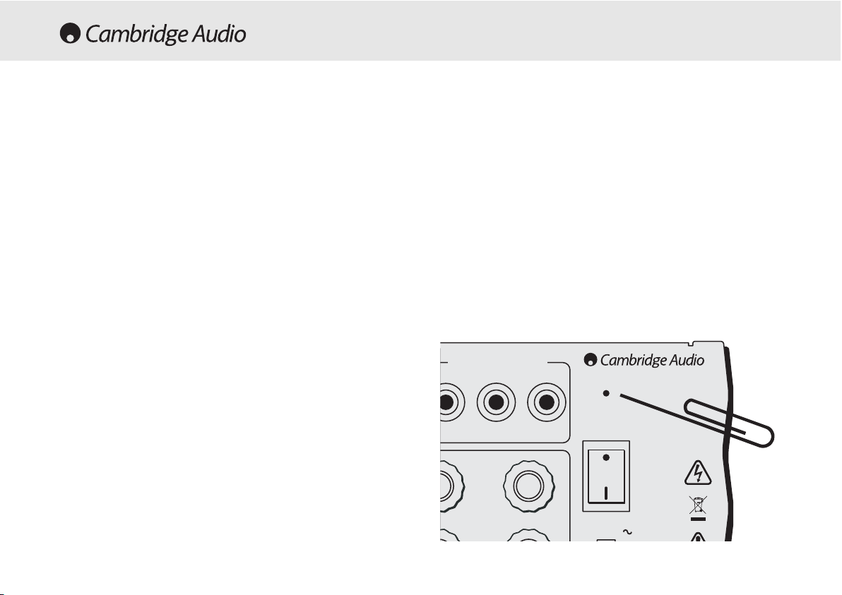
If it is desired to reset all settings to their factory defaults or in the
unlikely event that the unit locks up due to an electrical discharge etc,
switch the Power to On on the rear panel, and using a paper clip (see
diagram below), press and hold the Reset button for three seconds.
“RESET” will appear briefly on the front panel display before returning to
Standby mode.
RESET/BACK-UP MEMORY
Left
Reset
Power
On
Off
Power AC
r/Pr Cb/Pb Y
Component Video Out
www.cambridge-audio.com
Designed in London, England
The 540R V2.0 features a Control Bus input that allows un-modulated
remote control commands (positive logic, TTL level) to be received
electrically by the unit. These control commands are typically generated
by custom installation (multi-room) systems or remote IR receiver
systems. The Control Bus socket is colour-coded orange.
This unit features 'direct' IR/Control codes as well as toggle codes for
many of their features to simplify programming custom installation
systems. Special direct On/Off commands can be accessed on the
supplied remote control for teaching into C.I. systems as follows:
1. Press and hold the Standby/On button on the remote control. The
remote first generates it's standby (toggle) command. Keep the
button held down, after 12 seconds an AV receiver “On” command
will be generated. If the button is kept held down for a further 12
seconds, an AV receiver “Off” command is generated.
Repeat this procedure with the Mute, Sub On/Off, Stereo Mono and
Tuner AM/FM buttons to send On/Off commands. The Tuner AM/FM
button also provides unique FM and AM commands to allow switching to
a specific band.
A full code table for this product is available on the Cambridge Audio
website at
www.cambridge-aaudio.com
.
CUSTOM INSTALLATION (C.I.) USE
Page 29

540R V2.0 AV receiver
Azur AV receiver 29
A llow hhum oor bbuzz ssound ccan bbe hheard
Power cords or lighting placed near this product.
Analog inputs not connected securely.
Sound iis nnot aaudible ffrom oone cchannel
One of the input cords is disconnected.
The balance control is set to one side.
Speaker connections disconnected.
Sound ccuts ooff wwhen llistening tto mmusic oor tthere iis nno
sound eeven tthough ppower iis OON
Speaker impedance is less than prescribed for the 540R.
The unit is not adequetely ventilated.
Low bbass oor ““phasey” rresponse
Speaker polarity (+/-) of one or more speakers is reversed.
An uunusual hhissing nnoise iis hheard wwhen llistening tto tthe
broadcast iin sstereo, bbut nnot hheard wwhen llistening iin mmono
A slight noise may be heard because the method used for modulation of
FM stereo broadcasts is different than that used for mono broadcasts.
Aerial quality also effects the level of hiss heard.
TROUBLESHOOTING
Noise iis eexcessive iin bboth sstereo aand mmonaural
broadcasts
Poor location and/or direction of the antenna.
Transmitting station is too far away.
No ssound ffrom tthe rrear sspeakers
Source being played is not recorded in surround sound.
Cable not connected securely.
Surround speakers have been set to “None” in OSD setup menu.
No ssound ffrom tthe ccentre sspeaker
Surround mode button is not set to one of the Dolby Digital, DTS Neo:6
or Dolby Pro Logic II modes.
Centre speaker has been set to “None” in OSD setup menu.
No ssound ffrom tthe ssubwoofer
Sub has been set to ‘None’ in the OSD setup menu.
Remote ccontrol iis nnot wworking
The batteries are flat.
The remote is too far from the receiver or out of the effective range.
Page 30

30 Azur AV receiver
Power Output
100 watts rms per channel,
8 ohms, two channels driven
80 watts rms per channel,
8 ohms all 6 channels driven
THD
<0.006% @1kHz
Crosstalk
<-60dB
Frequency response
20Hz – 20kHz +/- 1dB
Audio Input Sensitivity
150mV
Audio
Input Impedance
47kOhms
Digital Input Impedance
75ohms (Coaxial/SPDIF)
S/N Ratio
>90dB ‘A’ weighted
Tone Control Range
Bass +/-6dB
Treble +/-6dB
FM Tuner
87.5-108MHz,
75 ohm coaxial aerial
AM Tuner
522-1629kHz,
300 ohm loop aerial
Video Input Impedance
75ohm
Stby power consumptio
n
<10w
Max power consumption
615w
Architecture
CS42518 CODEC
CS493263 DSP
Audio Inputs
6 Line Level + Tuner
6.1 Direct Input
TECHNICAL SPECIFICATIONS
Audio Outputs
6 Amplified Speaker Outputs
6.1 Preamp output
1 Tape record output
Video Inputs
4 Composite, 3 S-Video,
2 Component Video
Video Ouputs
1 Composite, 1 S-Video,
1 Component Video
Digital Inputs
4 Co-Axial, 3 Optical
Digital Outputs
1 Co-Axial, 1 Optical
Control Bus Input
Opto isolated, TTL positive logic,
Unmodulated
D
imensions - H x W x D
150 x 350 x 430mm
Weight
9.5kg (20.9lbs)
This guide is designed to make installing and using this product as easy as possible. Information
in this document has been carefully checked for accuracy at the time of printing; however,
Cambridge Audio's policy is one of continuous improvement, therefore design and specifications
are subject to change without prior notice. If you notice any errors please feel free to email us
at: support@cambridgeaudio.com
This document contains proprietary information protected by copyright. All rights are reserved.
No part of this manual may be reproduced by any mechanical, electronic or other means, in any
form, without prior written permission of the manufacturer. All trademarks and registered
trademarks are the property of their respective owners.
© Copyright Cambridge Audio Ltd 2005
“Dolby”, “Pro Logic”, “Surround EX” and the double-D symbol are trademarks of Dolby
Laboratories.
“DTS”, “DTS Digital Surround”, “DTS-ES” and “Neo:6” are trademarks of Digital Theater Systems,
Inc.
Page 31

540R V2.0 AV receiver
Azur AV receiver 31
Page 32

32 Azur-AV-Receiver
Einführung.................................................................................................33
Haftungsbeschränkung............................................................................34
Sicherheitsvorkehrungen .........................................................................35
Wichtige Sicherheitshinweise ..................................................................36
Anschlüsse an der Vorderseite des Geräts.............................................38
Anschlüsse an der Rückseite des Geräts...............................................40
Fernbedienung..........................................................................................42
Surround-Sound-Modi ..............................................................................44
Positionierung der Boxen.........................................................................45
Anschluss der Boxen ................................................................................46
Audioanschlüsse .......................................................................................47
Videoanschlüsse .......................................................................................47
Digitale Anschlüsse ..................................................................................48
6.1-Direct-Eingang.. ..................................................................................48
6.1-Vorverstärker-Ausgang.......................................................................49
Eingänge an der Vorderseite....................................................................49
Antennenanschlüsse................................................................................50
OSD-Display...............................................................................................50
OSD-Menüs................................................................................................51
Surround-Sound-Einrichtung....................................................................52
Anweisungen zur Bedienung....................................................................56
Verwendung mit kundenspezifischen Systemen....................................58
Reset/Backup-Speicher ...........................................................................58
Fehlersuche...............................................................................................59
Technische Daten.....................................................................................60
INHALTSVERZEICHNIS
Page 33

Außerdem besitzt der 540R V2.0 auch einen analogen 6.1-KanalEingang. Mit dieser Funktion lässt sich auch ein mit 5.1-/6.1-Ausgang
ausgestatteter Player mit DVD Audio oder SACD anschließen. Kurz
gesagt - der 540R V2.0 ist komplett dazu ausgestattet, diese
ultramodernen und spannenden Musikformate zu nutzen.
Neben dem kompletten Angebot an Audio-Eingängen besitzt der 540R
V2.0 auch die Möglichkeit, Composite Video, S-Video und Component
Video Signale weiter zu schalten. Das heißt, Sie können den 540R V2.0
auch als Hub für die Weiterleitung von Videosignalen neben den
Audiosignalen einsetzen.
Diese umfangreiche firmeneigene Technik steckt in unserem Chassis
mit niedriger Resonanz und akustischer Dämpfung. Eine Azur-NavigatorFernbedienung für alle Funktionen des AV-Receivers ist beigefügt und
zeichnet sich durch ihr attraktives Design und ihre leichte Handhabung
aus.
Der 540R V2.0 kann nur so gut wie das System sein, an das er
angeschlossen ist. Gehen Sie deshalb bei den Boxen oder bei den
Kabeln keine Kompromisse ein. Ganz besonders empfehlen wir Ihnen
natürlich die DVD-/CD-Player und andere Geräte aus der Azur Serie von
Cambridge Audio, die dieselben hohen Qualitätsanforderungen erfüllen
wie unsere Receiver. Ihr Händler hält für Sie qualitativ hochwertige
Verbindungskabel von Cambridge Audio bereit, mit denen Sie die
Möglichkeiten Ihres Systems optimal ausnutzen können.
Danke, dass Sie sich die Zeit zum Lesen dieses Handbuchs nehmen.
Wir empfehlen, dass Sie es für künftigen Gebrauch aufbewahren.
Matthew Bramble
Technischer Direktor
540R V2.0 AV-Receiver
Azur-AV-Receiver 33
Vielen DDank ffür IIhren KKauf ddieses AAV-RReceivers dder AAzur SSerie vvon
Cambridge AAudio. DDer 5540R iin VVersi
on 22 iist TTeil uunseres SStrebens, ddie
Azur SSerie ffortlaufend wweiterzuentwickeln. WWir hhoffen, ddass ddas EErgebnis
Ihre AAnsprüche eerfüllt uund SSie vviele JJahre FFreude aan iihm hhaben wwerden.
Zum 5540R VV2.0
Der 540R V2.0 ist für eine optimale Mehrkanal-Leistung ohne Abstriche
bei der Stereowiedergabe ausgelegt. Aus diesem Grund sind die sechs
einzelnen 80-Watt-Verstärker soweit wie möglich von der
Signalverarbeitung und den Eingängen getrennt gehalten. Ein
überdimensioniertes Netzteil sorgt dafür, dass der 540R V2.0 höchste
Leistung in gleichmäßige differenzierte Boxenimpulse umsetzen kann
und so für einen beeindruckenden und leichtgängigen Klang sorgt.
Für dieses V2.0-Modell haben wir eine verbesserte
Lautstärkeregelungs-IS und größere SV-Kondensatoren ausgewählt
sowie verschiedene Verbesserungen an den Schaltungen
vorgenommen, um die Klangqualität des Geräts weiter zu steigern. Die
Videoschaltverteilung wurde ebenfalls vollständig neu entwickelt, um
eine größere Bandbreite für HDTV zu bieten, und das Gerät bietet jetzt
vollständiges OSD-Display.
Der 540R V2.0 ist mit der ganzen Bandbreite digitaler und analoger
Eingänge ausgestattet. Die digitalen Eingänge bieten
Anschlussmöglichkeiten für entsprechend ausgelegte DVD-Player,
Satelliten-Boxen und Spielekonsolen mit Dekodierung in die DigitalSurround-Formate. Herkömmliche analoge Stereoeingänge ermöglichen
den Anschluss von CD-Playern und anderen Geräten, um die
bestmögliche Stereowiedergabe zu gewährleisten. Der 540R V2.0 kann
auch analoge Stereoausgangssignale in Dolby Pro Logic® II und DTS
Neo:6 dekodieren, um diese in echtem und beeindruckendem Surround
Sound zu genießen. Und damit nicht genug: Auch von Quellen wie dem
Fernseher und dem Videorecorder können Sie die Wiedergabe jetzt über
das Surround-System des 540R V2.0 anhören.
EINFÜHRUNG
Page 34

34 Azur-AV-Receiver
Cambridge Audio garantiert Ihnen, dass dieses Produkt keine Materialund Herstellungsfehler (wie im Folgenden näher erläutert) aufweist.
Cambridge Audio repariert oder ersetzt (nach der freien Entscheidung
von Cambridge Audio) dieses Produkt oder ein eventuelles defektes Teil
in diesem Produkt. Die Garantiedauer kann in den einzelnen Ländern
unterschiedlich sein. Wenn Sie Fragen zu der Garantie haben, wenden
Sie sich bitte an Ihren Händler. Bewahren Sie den Kaufnachweis immer
auf.
Wenn Sie Garantieleistungen in Anspruch nehmen möchten, wenden
Sie sich bitte an den von Cambridge Audio autorisierten Händler, bei
dem Sie das Produkt gekauft haben. Sollte dieser Händler nicht in der
Lage sein, Ihr Cambridge Audio-Produkt zu reparieren, kann dieser das
Produkt an Cambridge Audio oder eine autorisierte Cambridge AudioKundendienststelle zurücksenden. Das Produkt muss entweder in der
Originalverpackung oder einer Verpackung, die einen gleichwertigen
Schutz bietet, versandt werden.
Sie müssen einen Kaufnachweis in Form einer Kaufurkunde oder einer
quittierten Rechnung vorlegen, wenn Sie einen Anspruch auf
Garantieleistungen geltend machen. Aus diesem Kaufnachweis muss
abzulesen sein, dass sich das Produkt im Garantiezeitraum befindet.
Diese Garantie wird ungültig, wenn (a) die bei der Herstellung
angebrachte Seriennummer bei diesem Produkt geändert oder entfernt
wurde oder (b) dieses Produkt nicht bei einem von Cambridge Audio
autorisierten Händler gekauft wurde. Wenden Sie sich an Cambridge
Audio oder den lokalen Cambridge Audio-Vertrieb in Ihrem eigenen
Land, um sicher zu stellen, dass Ihre Seriennummer nicht geändert
wurde und/oder dass Sie bei einem von Cambridge Audio autorisierten
Händler gekauft haben.
Die Garantie gilt nicht für kosmetische Schäden oder Schäden durch
höhere Gewalt, Unfälle, unsachgemäße Behandlung, Unachtsamkeit,
kommerziellen Einsatz oder durch Änderungen des Produkts bzw. von
Teilen des Produkts. Diese Garantie umfasst keine Schäden durch
unsachgemäßen Betrieb, unsachgemäße Wartung oder Installation
oder durch Reparaturen, die von anderen Personen als von Cambridge
Audio oder einem Cambridge Audio-Händler oder einem autorisierten
Kundendienstmitarbeiter, der von Cambridge Audio für das Ausführen
von Garantieleistungen befugt ist, vorgenommen werden. Durch jede
nicht autorisierte Reparatur wird diese Garantie unwirksam. Diese
Garantie gilt nicht für Produkte, die verkauft werden AS IS (WIE SIE
SIND) oder WITH ALL FAULTS (MIT ALLEN FEHLERN).
DIE HAFTUNGSANSPRÜCHE DES BENUTZERS BESCHRÄNKEN SICH AUF
DIE IN DIESER GARANTIE ENTHALTENEN REPARATUREN ODER
ERSATZLEISTUNGEN. CAMBRIDGE AUDIO HAFTET NICHT FÜR
ZUFÄLLIGE ODER FOLGESCHÄDEN DURCH DIE VERLETZUNG
IRGENDEINER AUSDRÜCKLICHEN ODER IMPLIZITEN GARANTIE BEI
DIESEM PRODUKT. AUßER DORT, WO DIES GESETZLICH UNTERSAGT IST,
IST DIESE GARANTIE EXKLUSIV UND TRITT SIE AN DIE STELLE ALLER
ANDEREN AUSDRÜCKLICHEN ODER IMPLIZITEN GARANTIEN, WELCHER
ART AUCH IMMER, EINSCHLIEßLICH, ABER NICHT BESCHRÄNKT AUF,
VERKAUFSGARANTIE UND FUNKTIONSGARANTIE FÜR EINEN
PRAKTISCHEN ZWECK.
Einige Länder und US-Staaten erlauben keinen Ausschluss oder keine
Beschränkung von zufälligen oder Folgeschäden bzw. impliziten
Garantien, so dass die oben genannten Ausschlüsse für Sie eventuell
nicht gelten. Diese Garantie erteilt Ihnen spezifische gesetzliche Rechte;
es ist auch möglich, dass Sie andere Rechtsansprüche haben, die in
jedem Staat und jedem Land anders aussehen können.
HAFTUNGSBESCHRÄNKUNG
Page 35

540R V2.0 AV-Receiver
Azur-AV-Receiver 35
Kontrolle dder NNetzanschlussleistung
Bitte lesen Sie zu Ihrer eigenen Sicherheit die folgenden Anweisungen sorgfältig
durch, bevor Sie dieses Gerät an das Stromnetz anschließen.
Kontrollieren Sie, dass an der Rückseite des Gerätes die richtige Netzspannung
angegeben ist. Wenn Ihre Netzspannung von der angegebenen Spannung
abweicht, nehmen Sie bitte Kontakt mit Ihrem Händler auf.
Dieses Gerät funktioniert nur mit der Netzspannung und dem Spannungstyp,
die/der auf der Rückseite des Gerätes angegeben ist. Wenn das Gerät an eine
anders ausgelegte Stromversorgung angeschlossen wird, kann es beschädigt
werden.
Schalten Sie das Gerät aus, wenn es nicht verwendet wird, und benutzen Sie es
nicht ohne eine entsprechende Erdung. Um die Gefahr eines elektrischen Schlags
zu verringern, darf die Abdeckung (oder die Rückseite) des Geräts nicht entfernt
werden. Im Gerät befinden sich keine Teile, die vom Benutzer gewartet bzw.
repariert werden können. Überlassen Sie die Wartung qualifiziertem
Fachpersonal.
Das Symbol mit dem Blitz und der Pfeilspitze in einem gleichseitigen
Dreieck weist den Benutzer auf das Vorhandensein von nicht
isolierter "gefährlicher Spannung" im Inneren des Produkts hin, die
ausreichend stark sein kann, um die Gefahr eines elektrischen
Schlags für Personen darzustellen.
Das Ausrufungszeichen in einem gleichseitigen Dreieck weist den
Benutzer darauf hin, dass die mit diesem Produkt gelieferte
Dokumentation wichtige Betriebs- und Wartungsanweisungen für
das Gerät enthält.
SICHERHEITSVORKEHRUNGEN
Dieses Produkt erfüllt die europäische
Niederspannungsrichtlinie (73/23/EU) und die Richtlinien über
die Elektromagnetische Verträglichkeit (EMV) (89/336/EU),
wenn es in Übereinstimmung mit diesem Handbuch verwendet
und installiert wird. Damit das Produkt diese Richtlinien auch in
Zukunft erfüllt, darf bei diesem Gerät nur Zubehör von
Cambridge Audio verwendet werden, und die Wartung muss von
qualifizierten Kundendienstmitarbeitern ausgeführt werden.
Die durchgestrichene Abfalltonne auf Rädern ist das Symbol der
Europäischen Union, das das getrennte Sammeln von Elektro- und
Elektronikgeräten anzeigt. Dieses Gerät enthält elektrische und
elektronische Teile, die wiederverwendet, recycelt oder
wiederhergestellt werden können und nicht mit unsortiertem
normalem Restabfall entsorgt werden dürfen. Bitte geben Sie das
Gerät zurück oder wenden Sie sich für weitere Informationen an
Ihren Fachhändler, von dem Sie dieses Gerät gekauft haben.
Page 36

36 Azur-AV-Receiver
Bitte nehmen Sie sich einen Moment Zeit und lesen Sie diese Hinweise
durch, bevor Sie Ihren 540R V2.0 installieren; dadurch erhalten Sie die
optimale Leistung, und Sie verlängern die Lebensdauer Ihres Geräts. Bitte
bewahren Sie diese Anleitung für künftigen Gebrauch auf.
BBeellüüffttuunngg
WICHTIG - Das Gerät wird im Betrieb warm. Bitte gewährleisten Sie genug
Raum zur Belüftung um das Gerät. Lassen Sie an der Oberseite, an der
Rückseite und an den Seiten mindestens 10 cm Platz. Das Gerät darf nicht
auf einem Teppich oder einer anderen weichen Fläche aufgestellt werden,
und die Belüftungsschlitze an der Unterseite und an der Oberseite müssen
immer frei gehalten werden. Das Gerät darf nicht in einem Hohlraum, wie
z.B. einem Bücherbord oder einem Schrank, betrieben werden.
PPoossiittiioonniieerruunngg
Wählen Sie den Aufstellungsort sorgfältig aus. Vermeiden Sie direkte
Sonneneinstrahlung oder Wärmequellen. Vermeiden Sie auch Standorte, die
Vibrationen und übermäßigem Staub, Kälte oder Feuchtigkeit ausgesetzt
sind. Das Gerät darf nicht auf einer unebenen Fläche oder einem Regal
aufgestellt werden. Das Gerät könnte herunterfallen, dabei Kinder oder
Erwachsene ernsthaft verletzen, und das Gerät kann schwer beschädigt
werden. Stellen Sie keinen CD-Player oder andere Geräte auf das Gerät.
Tropfwasser, Spritzwasser oder andere Flüssigkeiten dürfen nicht an das
Gerät gelangen. Mit Flüssigkeit gefüllte Gegenstände, wie z.B. eine Vase,
dürfen deshalb nicht auf dem Gerät abgestellt werden. Sollte das Gerät
dennoch Flüssigkeit ausgesetzt worden sein, schalten Sie es sofort aus,
trennen Sie es von der Netzspannung und fragen Sie Ihren Händler um Rat.
Achten Sie darauf, dass keine kleinen Teile durch die Lüftungsgitter fallen
können. Sollte dennoch ein kleines Teil in das Gerät gelangt sein, schalten
Sie es sofort aus, trennen Sie es von der Stromversorgung und fragen Sie
Ihren Händler um Rat.
Elektronische Audiokomponenten benötigen ca. eine Woche für die
Anpassung an die Umgebung (wenn das Gerät in dieser Zeit mehrere
Stunden täglich benutzt wird). Während dieser Zeitspanne entwickeln die
neuen Teile ihre gewünschten Eigenschaften, und die Klangqualität
verbessert sich.
EErrdduunngg uunndd PPoollaarriissiieerruunngg
Das Gerät ist unter Umständen mit einem polarisierten Netzstecker
ausgestattet. (In diesem Fall ist ein Steckstift breiter als der andere.) Ein
solcher Stecker lässt sich nur auf eine Weise in die Steckdose einsetzen.
Hierbei handelt es sich um eine Sicherheitsfunktion. Wenn Sie den
Netzstecker nicht vollständig in die Steckdose einsetzen können, drehen Sie
bitte den Stecker herum und versuchen Sie es noch einmal. Wenn der
Stecker sich jetzt immer noch nicht einsetzen lässt, ziehen Sie bitte Ihren
Elektriker zu Rate. Die Sicherheitsvorkehrung am polarisierten Stecker darf
nicht entfernt bzw. überbrückt werden. (Nur Nordamerika)
SSttrroommvveerrssoorrgguunngg
Das Gerät muss mit einer Stromversorgung betrieben werden, die derjenigen
auf dem Typenschild entspricht. Wenn Sie nicht sicher sind, welche Art der
Stromversorgung bei Ihnen Zuhause vorliegt, wenden Sie sich bitte an Ihren
Händler oder an den örtlichen Stromversorger.
Dieses Gerät wurde so ausgelegt, dass es in den Standby-Modus geht, wenn
es nicht benutzt wird, dadurch wird die Lebensdauer der Geräts verlängert
(das gilt für alle Elektrogeräte). Wenn Sie das Gerät über einen längeren
Zeitraum nicht benutzen möchten, schalten Sie es aus und ziehen Sie den
Stecker von der Steckdose ab.
SScchhuuttzz ddeess SSttrroommkkaabbeellss
Alle Stromkabel müssen so verlegt werden, dass nicht die Gefahr besteht,
dass man auf sie tritt, und dass keine Druck- oder Quetschwirkung durch auf
sie oder gegen sie gestellte Gegenstände besteht. Besonders beachtet
werden müssen dabei: die Verlegung des Stromkabels zur Steckdose und
der Anschluss des Stromkabels am Gerät.
Achten Sie darauf, alle Stromkabel richtig einzustecken. Bündeln Sie nicht
die Anschlusskabel mit dem Stromkabel oder den Boxenkabeln, um
Brummtöne und Störgeräusche zu vermeiden.
WICHTIGE INFORMATIONEN FÜR IHRE SICHERHEIT
Page 37

540R V2.0 AV-Receiver
Azur-AV-Receiver 37
ÜÜbbeerrbbeellaassttuunngg
Die Steckdose bzw. das Verlängerungskabel dürfen nicht überlastet werden,
da sonst die Gefahr eines Brands oder eines Stromschlags droht. Überlastete
Steckdosen, Verlängerungskabel, durchgescheuerte Kabel, beschädigte
oder gebrochene Isolierungen und beschädigte Netzstecker sind
Gefahrenpotenziale. Sie können zu Stromschlägen oder Bränden führen.
BBlliittzzsscchhllaagg
Schützen Sie das Gerät bei einem Gewitter oder wenn es längere Zeit
unbeaufsichtigt ist bzw. nicht verwendet wird, indem Sie den Gerätestecker
von der Steckdose abnehmen und die Verbindung mit dem Antennen- bzw.
Kabelsystem unterbrechen. Auf diese Weise können Sie das Gerät vor den
Einwirkungen von Blitzschlag und Überspannungen im Stromnetz schützen.
EErrdduunngg ddeerr AAuußßeennaanntteennnnee
Wenn das Gerät mit einer Außenantenne oder einem Kabelsystem
verbunden wird, muss das Antennen- bzw. Kabelsystem geerdet sein, damit
ein Schutz vor Spannungsspitzen und statischen Entladungen vorhanden ist.
Abschnitt 810 des National Electrical Code, ANSI/NIPA Nr. 70-1984
(Abschnitt 54 des Canadian Electrical Code, Teil 1) bieten Hinweise zur
ordnungsgemäßen Erdung des Masts und der Halterungsstruktur, zur Erdung
des Zuleitungkabels zu einem Antennen-Entladungselement, zur Größe der
Erdungsleitungen, zur Position des Entladungselements, zum Anschluss der
Erdungselektroden und zur Auslegung der Erdungselektrode.
RReeiinniigguunngg ddeess GGeerräättss
Trennen Sie das Gerät vor dem Reinigen von der Stromversorgung. Sie
reinigen das Gerät, indem Sie das Gehäuse mit einem feuchten, fusselfreien
Tuch abwischen. Verwenden Sie keine Reinigungsflüssigkeiten, die Alkohol,
Ammoniak oder Scheuermittel enthalten. Verwenden Sie bei oder in der
Nähe Ihres Geräts keine Spraydosen.
ZZuubbeehhöörr
Bitte verwenden Sie nur vom Hersteller empfohlenes Zubehör, da sonst die
Gefahr einer Beschädigung des Geräts besteht.
WWaarrttuunngg uunndd RReeppaarraattuurr
Das Gerät kann nicht vom Benutzer gewartet oder repariert werden.
Versuchen Sie deshalb nie, Reparaturen selbst durchzuführen, und
unterlassen Sie das Auseinandernehmen und Zusammenbauen des Geräts
bei einem Problem. Wenn diese Sicherheitsmaßnahme nicht beachtet wird,
kann dies einen gefährlichen elektrischen Schlag zur Folge haben. Nehmen
Sie bei einem Problem oder Ausfall des Geräts Kontakt mit Ihrem Händler
auf.
Bitte wenden Sie sich in folgenden Fällen an den Kundendienst:
- Das Netzkabel oder der Netzstecker ist beschädigt.
- Flüssigkeit ist an/in das Gerät gelangt oder ein Gegenstand ist in den
Verstärker gekommen.
- Das Gerät war Regen oder Wasser ausgesetzt.
- Das Gerät funktioniert nicht wie in der Bedienungsanleitung beschrieben.
Bedienen Sie aber bitte immer nur die Bedienelemente, die in der Anleitung
benannt werden.
- Das Gerät wurde fallen gelassen oder anderweitig beschädigt.
- Das Gerät weicht deutlich von den früheren Leistungsmerkmalen ab.
WWiicchhttiiggeerr HHiinnwweeiiss
Bei ssehr sstarker BBelastung ddes GGeräts kkann ees vvorkommen, ddass dder SSensor
eine zzu hhohe TTemperatur ffests
tellt. IIm DDisplay eerscheint ddann ddie
Warnmeldung ""PROTECTION OOVERLOAD" ((Schutzschaltung aaktiviert). DDa
s
Gerät sschaltet ddann aauf SStandby-BBetrieb uum. EEs kkann eerst ddann wwieder
eingeschaltet wwerden, wwenn ddie TT
emperatur iim nnormalen BBereich iist.
Page 38

38 Azur-AV-Receiver
Standby/Ein
Mit dieser Taste können Sie zwischen Standby (schwach leuchtende
Status-LED) und ON (Ein) (hell leuchtende Status-LED) wechseln.
Standby ist ein Bereitschaftsmodus mit einem Stromverbrauch von
unter 10 W. Lassen Sie das Gerät bei Nichtgebrauch im Standby-Modus.
Kopfhörer
Für den Anschluss von Stereokopfhörern mit ¼-Zoll-Stecker. Wir
empfehlen Kopfhörer mit einer Impedanz von 32 bis 600 Ohm.
Tuning ++/-
Regler für UKW-Sender und zum Überspringen von gespeicherten
Sendeplätzen bei der Senderwahl.
Modus/Speichern
Mit dieser Taste können Sie die Funktionen des Tuners nacheinander
einstellen (weitere Informationen hierzu finden Sie im Abschnitt
'Anweisungen zur Bedienung' des vorliegenden Handbuchs).
Stereo
Mit dieser Taste können Sie einen analogen oder einen digitalen (LPCM)
Stereotitel (abhängig vom Eingangsmodus) ausschließlich aus den
vorderen rechten und linken Boxen hören.
Dolby DDigital EEX // DDTS EES
Mit dieser Taste können Sie verschiedene Standard-Dolby-Digital- oder
DTS-Surround-5.1-Modi (mit entsprechend kodiertem digitalen
Ausgangsmaterial) auswählen. Ermöglicht auch die Auswahl der Modi
Dolby Digital EX und DTS ES, die 6.1-Ausgabe von entsprechend
kodiertem EX/ES-Material bieten. Diese Modi können nur von digitalen
Audioquellen (über koaxiale oder optische Eingänge) dekodiert werden.
Außerdem ist ein Autodetect-Modus verfügbar, der dem 540R V2.0
erlaubt, sich automatisch auf den richtigen Modus für digitales Material
einzustellen.
Volume
Phones Tuning Mode/Store
DVD Video 1
Dolby Digital EX/
DTS ES
DSP
Mode
Pro Logic II/
Neo 6
Input
Mode
Video 3 inputs
Video Left Right
Stereo
Video 2 Video 3 Tuner FM/AM Tape/MD/CDR CD/Aux 6.1 Direct
–+
Standby / On
azur 540R
AV Receiver
BEDIENELEMENTE AN DER VORDERSEITE
1
2
3
5
1 2 3 4
5 6 7 8 9
10 11 12 13 14 15 16 17
18
19
20
4
6
Page 39

540R V2.0 AV-Receiver
Azur-AV-Receiver 39
Pro LLogic III // NNeo:6
Mit dieser Taste können Sie entsprechend kodiertes analoges
Stereoausgangsmaterial in Surround Sound dekodieren. Die
automatische Erkennung dieser Modi ist nicht möglich, daher müssen
sie manuell ausgewählt werden.
DSP-MModus
Der 540R V2.0 kann selbst von nicht kodiertem Material durch Digital
Signal Processing (DSP) einen Surround-Sound-Effekt erzeugen. Hier
lassen sich folgende Surround-Sound-Effekte einstellen: THEATER,
HALL, MOVIE, MUSIC oder ROOM.
Eingangsmodus
Mit dieser Taste können Sie zwischen analogen oder
optischen/koaxialen Digitaleingängen für das derzeit ausgewählte
Gerät wählen. Der 540R V2.0 erinnert sich an die für jedes Gerät
gewählte Eingangsart, wenn Sie zu dem Gerät zurückkehren.
DVD
Drücken Sie diese Taste für die Wiedergabe eines DVD-Geräts über den
540R V2.0.
Video 11
Drücken Sie diese Taste für die Wiedergabe des an Video 1
angeschlossenen Geräts über den 540R V2.0.
Video 22
Drücken Sie diese Taste für die Wiedergabe des an Video 2
angeschlossenen Geräts über den 540R V2.0.
Video 33
Auswahl des Geräts, das an Video 3 an der Vorderseite des 540R V2.0
angeschlossen ist.
Tuner FFM/AM
Mit dieser Taste kann der Tuner für die Wiedergabe über den 540R V2.0
ausgewählt werden. Bei aktivierter Funktion Tuner wird hier zwischen
FM (UKW) und AM (MW) umgeschaltet.
Kasette/MD/CDR
Mit dieser Taste wird das an den Kassetten-/MD-/CDR-Eingang
angeschlossene Aufzeichnungsgerät für die Wiedergabe über den 540R
V2.0 ausgewählt.
CD/Aux
Schaltet ein an der Rückseite des 540R V2.0 angeschlossenes CDGerät oder anderes Gerät zu.
6.1 DDirect
Schaltet einen an die 6.1-Direct-Eingänge angeschlossenen 5.1- oder
6.1-DVD-A- oder SACD-Player zu.
Infrarot-SSensor
Empfängt IR-Befehle von der Azur-Fernbedienung. Erfordert eine freie,
ungehinderte Sichtlinie zwischen der Fernbedienung und dem Sensor.
Lautstärke
Mit der Lautstärkeregelung wird die Lautstärke an den Ausgängen des
540R V2.0 eingestellt.
Video-33-EEingänge
Ermöglicht den Anschluss einer Videokamera/Spielekonsole und deren
Auswahl durch die Video-3-Taste.
7
8
10
9
11
15
16
17
18
19
12
13
14
20
Page 40

40 Azur-AV-Receiver
FM/AM-AAntenne
Alle Anschlüsse Tuner / Antenne werden hier vorgenommen. Siehe
Abschnitt 'Antennenanschluss' in diesem Handbuch für weitere
Informationen.
TV/Mon-AAusgänge
S-Video - Anschluss an Ihren Fernseher über S-Video-Kabel zur Anzeige
des Bildes von mittels S-Video angeschlossenen Geräten.
Composite - Anschluss an Ihren Fernseher über RCA-Phono-Kabel zur
Anzeige des Bildes von mittels Composite Video
angeschlossenen Geräten.
Diese Ausgänge werden auch für die Anzeige des OSD-Setup-Menüs des
540R V2.0 verwendet.
S-VVideo-EEingänge
Anschluss der S-Video-Ausgänge der Quellgeräte.
Composite-VVideo-EEingänge
Anschluss der Composite-Video-Ausgänge der Quellgeräte.
Component-VVideo-EEingänge
Anschluss der Component-Video-Ausgänge der Quellgeräte.
Hinweis:
Die bevorzugte Anschlussmethode für Videogeräte ist immer
Component Video (beste Qualität), dann S-Video und schließlich
Composite Video. Component-Video-DVD-Geräte unterstützen auch oft
Progressive Scan, das eine bessere Bildqualität bietet, wenn es von
Ihrem DVD-Player und Ihrem Fernseher unterstützt wird.
Component-VVideo-AAusgang
Anschluss an die Cr/Pr-, Cb/Pb- und Y-Anschlüsse von Fernsehern.
Hinweis:
Component-Video-Ausgänge bieten kein OSD-Setup-Menü.
ANSCHLÜSSE AN DER RÜCKSEITE DES GERÄTS
1
1
2 3
4
7
9
8
10
11
5 6
12
13
14
151617
1819
20
2
3
4
5
6
FM 75Ω
TV/Mon Out
S-VideoComposite
L
R
RS232C
CD/Aux
S-Video In
Video 2 Video 1 DVD CD Video 1/Video 2 DVD
Video 2 Video 1 DVD
Composite Video In
Audio In
Video 2 Video 1 DVD
Optical In
CD DVD
Video 1/Video 2
Coax InCoax In Coax Out
Tape
L
R
Tape Play Tape Rec
Optical
Out
RR
azur 540R V2.0
AV Receiver
Loop
300Ω
This device
complies with
part 15 of
FCC rules
Tuner
Manufactured
in an ISO9002
approved facility
Caution / Avis /Achtung
Risk of electric shock
Do not open
Risque de choc electrique
Ne pas ouvrir
Vorm öffnen des gërates
Netzstecker ziehen
AM
Component Video In
DVD
Cr/Pr Cb/Pb Y Cr/Pr Cb/Pb Y Cr/Pr Cb/Pb Y
Control
Bus
SL SLLL
SR SR
6.1 Direct In
SB
Cen C
SB
SW SW
In
6.1 Preamp Out
Video 1/Video 2
Sur
Left
Sur
Right
Sur
Back
Speaker Impedance 4-8 Ohms
Component Video Out
Right
Centre
Designed in London, England
www.cambridge-audio.com
Reset
On
Power
Power AC
Off
Left
Power Rating: 230V AC 50Hz
Max Power Consumption: 615W
Serial No. label fitted on underside
Page 41

540R V2.0 AV-Receiver
Azur-AV-Receiver 41
Opto-EEingänge
Anschluss an digitale, optische (Toslink) Ausgänge von Quellgeräten.
Opto-AAusgang
Anschluss an den digitalen, optischen (Toslink) Eingang eines externen
Aufzeichnungsgeräts (z.B. MD/CDR etc.) zur Aufzeichnung vom
gewählten digitalen Audiogerät.
Coax-EEingänge
Anschluss an digitale, koaxiale (SPDIF) Ausgänge von Quellgeräten.
Coax-AAusgang
Anschluss an den digitalen, koaxialen (SPDIF) Eingang eines externen
Aufzeichnungsgeräts (z.B. MD/CDR etc.) zur Aufzeichnung vom
gewählten digitalen Audiogerät.
Kontrollbuseingang
Damit kann der 540R V2.0 unmodulierte Befehle von
Mehrraumsystemen oder anderen Komponenten empfangen.
Reset
Rücksetzung auf alle werkseitig eingestellten Vorgabewerte. Siehe den
Abschnitt 'Reset/Backup-Speicher' dieses Handbuchs für weitere
Informationen.
Power OOn // OOff ((Ein/Aus)
Hiermit schalten Sie das Gerät ein und aus.
Stromkabel
Nachdem Sie alle Anschlüsse vorgenommen haben, stecken Sie das
Stromkabel in eine geeignete Steckdose. Jetzt ist der AV-Receiver einsatzbereit.
Boxenanschlüsse
Hier können Boxen mit einer Impedanz von 4 bis 8 Ohm angeschlossen
werden.
6.1-VVorverstärker-AAusgang
Hier kann der 6.1-kanalige (oder 5.1-kanalige) Eingang eines anderen
Verstärkers, von separaten Leistungsverstärkern, eines Subwoofers
oder von Aktivboxen eingesteckt werden.
6.1-DDirect-EEingang
Anschluss an den 6.1-kanaligen (oder 5.1-kanaligen) Ausgang eines
DVD-Players mit eingebauter Surround-Sound-Dekodierung zur
Wiedergabe von DVD-A oder SACD.
Kassette
Anschluss der Kassettenanschlüsse an die Leitungsausgänge eines
Kassettengeräts, MD-Players, CD-R-Geräts etc. Anschluss der
Kassettenrekorderanschlüsse an die Leitungseingänge eines
Kassettengeräts, MD-Players, CD-R-Geräts etc.
Audio-EEingänge
Anschluss an die Audioleitungsausgänge des Quellgeräts (z.B. CDPlayer, DVD-Player etc.).
RS232C
Für die Verwendung durch einen Installateur/Händler für
Softwareaktualisierungen.
7
14
15
16
17
18
19
20
13
8
9
10
11
12
Page 42

CH SSelect ((Kanalwahl ffür BBoxenabgleich)
Drücken Sie die Taste für die Auswahl einzelner Kanäle,
verwenden Sie dann die Lautstärke für den Abgleich der Boxen.
Sub oon/off ((Subwoofer EEIN/AUS)
Drücken Sie die Taste, um die Ausgabe des Subwoofers ein- oder
auszuschalten.
Delay ((Verzögerung)
Drücken Sie die Taste, um die Verzögerungszeiten bei der
Einstellung der Surround-Sound-Boxen festzulegen.
SPK SSetup ((Boxen eeinstellen)
Drücken Sie die Taste, um die Einstellungen der Surround-SoundBoxen zu ändern.
OSD-DDisplay
Drücken Sie die Taste, um auf das OSD-Setup-Menü zuzugreifen,
wenn ein Bildschirm über Composite oder S-Video angeschlossen ist.
Mute ((Stummschalten)
Mit dieser Taste können Sie den Ton am AV-Receiver
stummschalten. Bei aktivierter Stummschaltung blinkt die KanalLED. Drücken Sie die Taste erneut, um den Ton wieder
einzuschalten.
Lautstärke
Erhöhen oder reduzieren Sie die Lautstärke am Ausgang des AVReceivers. Wird auch als aufwärts/abwärts im OSD-Setup-Menü
verwendet.
42 Azur-AV-Receiver
FERNBEDIENUNG
Der 540R V2.0 besitzt eine Azur-Navigator-Fernbedienung. Legen
Sie die mitgelieferten AAA-Batterien zur Inbetriebnahme ein.
Weitere Informationen über die verschiedenen über die
Fernbedienung verfügbaren Einstellungsfunktionen finden Sie in
späteren Abschnitten des vorliegenden Handbuchs.
Standby/Ein
Mit dieser Taste können Sie zwischen Standby und ON (Ein)
wechseln.
Eingangsmodus
Umschaltung zwischen analogen und digitalen Eingängen für das
derzeit ausgewählte Gerät am 540R V2.0.
Stereo-,, PPLII/NEO:6-,, DDD EEX-//DTS EES-,, DDSP-MModus
Siehe weitere Informationen im Abschnitt 'Bedienungselemente an
der Vorderseite'.
Dynamic ((Dynamikbereich)
Bitte betätigen Sie die Taste Dynamic an der Fernbedienung
solange, bis die gewünschte Kompression erreicht wurde (nur bei
Dolby Digital).
LFE-EEinstellung ((Niederfrequenzen)
Einstellung der Niederfrequenz (Subwoofer).
Test TTone ((für dden PPegelabgleich dder BBoxen)
Prüftöne für die Einstellung Ihrer Surround-Sound-Boxen.
Stereo
Input
Mode
6.1
Direct
DSP
Mode
Dynamic
PL II
Neo 6
DD EX
DTS ES
Test
ToneCHSelect
LFE
Trim
Sub
On/Off
Delay
Tuner
AM/FM
Bass
Treble
ModeStore
Stereo
Mono
DisplayPTY APS
SPK
Setup
DVD Video 1 Video 2
Video 3
CD
Aux
Tape
MD/CDR
Enter
Vol
Vol
Page 43

Tune ((Senderwahl)
Drücken Sie den Pfeil nach rechts, um die TunerFrequenz/Sendeplatzänderung zu erhöhen. Drücken Sie den Pfeil nach
links, um die Tuner-Frequenz/Sendeplatzänderung zu verringern. Wird
auch verwendet, um im ODS-Setup-Menü nach links/rechts zu gehen.
Enter ((Eingabe)
Wird im OSD-Setup-Menü verwendet.
6.1 DDirect
Zur Auswahl des 5.1-/6.1-Direct-Eingangs.
Bass // TTreble ((Bässe/Höhen)
Drücken Sie diese Taste zur Einstellung der Bässe/Höhen, verwenden
Sie dann die Lautstärketasten.
PTY ((Suche nnach PProgrammart)
Suche nach Programmart bei der Senderwahl.
APS ((Automatische PProgrammsuche)
Automatisches Suchen und Speichern von Radiosendern.
Display ((Anzeigen)
Wenn die Wiedergabe von einem externen Gerät stammt, kann hier die
Art des Eingangs überprüft werden (Opto-, Koaxial- oder Analogeingang).
Wenn die Wiedergabe von UKW (FM) mit RDS stammt, können hier
Informationen über den Radiosender abgelesen werden.
540R V2.0 AV-Receiver
Azur-AV-Receiver 43
Stereo MMono
Bei Wiedergabe von UKW (FM) kann hier zwischen Stereo- und
Monowiedergabe gewechselt werden.
Store ((Speichern)
Zur Speicherung der aktuellen Frequenz bei der Senderwahl.
Mode ((Modus)
Zur Auswahl von Auto-/Manual- oder Preset-Einstellung bei der
Senderwahl.
Tuner FFM/AM, DDVD, VVideo 11, VVideo 22, VVideo 33,
Kassette/MD/CDR, CCD/Aux
Drücken Sie die entsprechende Taste zur Änderung des Eingangsquelle.
Wenn Sie die Taste Tuner AM/FM ein zweites Mal drücken, wird
zwischen den Modi FM und AM gewechselt.
Siehe AAbschnitt ''Anweisungen zzur BBedienung' ddieses
Handbuchs ffür wweitere IInformationen zzu dden FFunktion
en ddieser
Tasten.
Page 44

44 Azur-AV-Receiver
Der 540R V2.0 bietet verschiedene Musik- und Heimkinomodi, die alle
für die Wiedergabe von Surround-Sound-Effekten ausgelegt sind,
abhängig vom Eingangssignal und der Boxeneinrichtung.
Stereo
In diesem Modus erfolgt die Ausgabe nur über die vordere rechte und
die vordere linke Box (und den Subwoofer, wenn er ausgewählt ist).
Wenn eine analoge Quelle ausgewählt ist, hören Sie reinen analogen
Stereoton ohne Digital Signal Processing (DSP). Wenn eine digitale
Quelle ausgewählt ist, fungiert der 540R V2.0 als D/A-Wandler und gibt
Stereo-LPCM für CD-Player etc. aus.
Dolby DDigital ((5.1)
Bietet (bis zu) 5.1-Ausgabe von entsprechend kodiertem Dolby-DigitalMaterial über 5 Hauptboxen (Links vorne , Rechts vorne, Mitte, Links
Surround, Rechts Surround) und einen Subwoofer. Zur Dekodierung von
Dolby Digital sind eine Dolby-Digital-kodierte DVD und ein digitaler
Anschluss vom 540R V2.0 zum angeschlossenen Gerät (beispielsweise
ein DVD-Player) erforderlich.
DTS ((5.1)
DTS bietet ebenfalls (bis zu) 5.1-Ausgabe von entsprechend kodiertem
DTS-Material über 5 Hauptboxen (Links vorne, Rechts vorne, Mitte,
Links Surround, Rechts Surround) und einen Subwoofer. Zur
Dekodierung von DTS sind eine entsprechend kodierte DTS-Disk und ein
digitaler Anschluss vom 540R V2.0 zum angeschlossenen Gerät
erforderlich.
Dolby DDigital EEX ((6.1)
Eine Erweiterung von Dolby Digital, DD EX bietet einen zusätzlichen Kanal
(Surround Back) für größere Bildtiefe und bessere Sound-Lokalisierung
hinter dem Hörer. DD EX erfordert eine DD-EX-kodierte Disk.
SURROUND-SOUND-MODI
DTS-EES DDiscrete ((6.1)
Eine Erweiterung von DTS, ES bietet einen zusätzlichen Kanal (Surround
Back) für größere Bildtiefe und bessere Sound-Lokalisierung hinter dem
Hörer. Alle Kanäle sind für bestmöglichen Surround-Sound-Effekt
getrennt digital kodiert. DT-ES Discrete erfordert eine DT-ES-Discretekodierte Disk.
DTS-EES MMatrix ((6.1)
Eine weitere Erweiterung von DTS, ES Matrix bietet ebenfalls einen
zusätzlichen Kanal (Surround Back), dieser ist jedoch in den linken und
rechten Surround-Kanal in einem Matrixprozess integriert. DTS ES
Matrix erfordert eine DTS-ES-Matrix-kodierte Disk.
Pro LLogic III
Eine neuere Version von Dolby Pro Logic, die 5.1-Surround-Sound von
entsprechend kodierten analogen Quellen wiedergeben kann. Die
Quelle ist eine Stereoquelle (und kann so abgespielt werden), besitzt
jedoch auch eine spezielle Kodierung, die es dem 540R V2.0 erlaubt,
eine 5.1-Surround-Sound-Ausgabe zu dekodieren. Es gibt 5
Standardmodi: Movie, Music, Virtual, Pro Logic Emulation und Matrix.
DTS NNeo:6
Eine DTS-Technologie, die 6.1-Surround-Sound von entsprechend kodierten
Analogquellen wiedergeben kann. Die Quelle ist eine Stereoquelle (und
kann so abgespielt werden), besitzt jedoch auch eine spezielle Kodierung,
die es dem 540R V2.0 erlaubt, eine 6,1-Surround-Sound-Ausgabe zu
dekodieren. Es gibt 2 Standardmodi: Cinema und Music.
DSP-MModi
Diese Modi erlauben eine realistische Surround-Sound-Erfahrung von
Quellen ohne Kodierung. Der Surround-Sound-Effekt wird durch Digital
Signal Processing von verwendeten analogen oder digitalen Stereoquellen
erreicht. Es gibt 5 Modi: Theater, Hall, Movie, Music und Room.
Page 45

540R V2.0 AV-Receiver
Azur-AV-Receiver 45
Die Abbildung zeigt eine typische 5.1-/6.1-Boxenaufstellung. Passen Sie
die Positionen der Boxen und des Zuhörers an, bis Sie mit dem Klang
zufrieden sind. Weitere Informationen zur Aufstellung finden Sie in den
Handbüchern der Boxen und des Subwoofers.
Boxen vvorne llinks uund rrechts -
Für Stereo- und Mehrkanal-Sound.
Auf Hörposition ausrichten.
Mittlere BBox -
Für Dialoge und mittige Sounds. Auf einer ähnlichen
Höhe wie die Boxen vorne rechts und links anbringen (über oder unter
dem Fernseher/Bildschirm). Es ist ratsam, dass die mittlere Box vom
gleichern Hersteller/aus der gleichen Serie stammt wie die Boxen vorne
rechts und links. Das "passende Timbre" ermöglicht es SurroundEffekten natürlicher von links nach rechts zu fließen, ohne
offensichtliche Übergänge zwischen den Boxen.
Surround-BBoxen llinks uund rrechts -
Für Umgebungs- und MehrkanalSound. Auf dem Boden stehende Boxen sollten auf die Hörposition
ausgerichtet werden. Boxen in Bücherregalen/auf Ständern sollten an
die Wand montiert oder mit speziellen Boxenständern verwendet
werden und auf Ohrhöhe oder darüber positioniert werden. Um die
erforderliche Verzögerung zwischen den Boxen für die Surround-SoundModi einzustellen, beachten Sie bitte den Abschnitt 'Surround-SoundEinrichtung' des vorliegenden Handbuchs.
Surround-BBack-BBox
-
Optionale Box für den sechsten Kanal,
erforderlich für Dolby® Digital EX oder DTS®-ES. Sie erhöht die
Soundqualität, weil die Lücke zwischen den linken und rechten
Surround-Boxen geschlossen wird. Stellen Sie die Box so auf, dass sie
zum vorderen Teil des Raumes zeigt.
Subwoofer -
Zur Verbesserung der Bässe in Ihrem System, sowie zur
Wiedergabe von LFE-Kinoeffekten beim Abspielen von Dolby-Digitaloder DTS-kodierten Disks. Ihr Subwoofer kann fast überall im Raum
aufgestellt werden, da Bässe weniger direktional sind, doch wir
empfehlen, verschiedene Positionen auszuprobieren.
POSITIONIERUNG DER BOXEN
1
2
3
5
4
55..11//66..11
1 1
2
4
3
3
5
**
* Freigestellt
Page 46

46 Azur-AV-Receiver
Bitte schalten Sie das Gerät vor dem Anschließen der Boxen immer aus,
damit ein unerwartet starkes Signal die Boxen nicht beschädigen kann.
Überprüfen Sie die Impedanz Ihrer Boxen. Wir empfehlen Boxen mit
einer Impedanz von (jeweils) 4 bis 8 Ohm.
Die farbigen Boxenanschlüsse sind positiv (+) und die schwarzen
Boxenanschlüsse sind negativ (-). Achten Sie auf korrekte Polarität an
jedem Boxenanschluss, sonst kann der Klang schwach und "phasig" mit
wenig Bässen werden.
Bereiten Sie die Boxenkabel für den Anschluss vor, indem Sie ca. 10 mm
oder weniger (nicht mehr als 10 mm, da dies zu einem Kurzschluss
führen könnte) der äußeren Isolierung entfernen. Verseilen Sie die
Drähte eng miteinander, so dass keine losen Enden bleiben. Lösen Sie
die Boxanschlussschraube, stecken Sie das Boxenkabel ein, ziehen Sie
die Schraube an und befestigen Sie so das Kabel.
Hinweis:
Alle Anschlüsse erfolgen über Boxenkabel, außer bei
Verwendung eines Aktivsubwoofers, der über ein Standard-RCAPhonokabel angeschlossen wird. Empfohlen werden an das Boxenkabel
angeschlossene Bananenstecker (4 mm) zum direkten Einstecken in die
Boxenanschlüsse.
ANSCHLUSS DER BOXEN
Power Rating: 230V AC 50Hz
Sur
Left
Sur
Right
Sur
Back
Left
Right
Centre
Reset
Power
On
Off
SB
SB
SW SW
Cen C
SR
R
SL L
Power AC
Max Power Consumption: 615W
t In
6.1 Preamp Out
Cr/Pr Cb/Pb Y Cr/Pr Cb/Pb Y Cr/Pr Cb/Pb Y
Component Video In
DVD
Video 1/Video 2
Component Video Out
www.cambridge-audio.com
Designed in London, England
Speaker Impedance 4-8 Ohms
Control
Bus
Serial No. label fitted on underside
In
RReecchhttee
vvoorrddeerree BBooxx
LLiinnkkee vvoorrddeerree
BBooxx
LLiinnkkee
SSuurrrroouunndd-BBooxx
RReecchhttee
SSuurrrroouunndd-BBooxx
MMiittttlleerree vvoorrddeerree
BBooxx
SSuur
rrroouunndd-BBaacckk-
BBooxx
AAkkttiivvssuubbwwooooffeerr
PPhhoonnoo-//RRCCAA-KKaabbeell
Page 47

540R V2.0 AV-Receiver
Azur-AV-Receiver 47
VIDEO-ANSCHLÜSSE
AUDIO-ANSCHLÜSSE
Hinweis:
Schließen Sie das Stromkabel nicht an und schalten Sie das
Gerät nicht ein, bevor alle Anschlüsse vorgenommen wurden.
Zum Anschluss Ihres externen Geräts mit Stereo-Phonokabeln (Stereo2RCA-2RCA). Kassetten-/MD-/CDR-Rekorder/Player erfordern zwei Sets
an Stereo-Phono-/RCA-Kabeln, eins für die Aufnahme, eins für die
Wiedergabe.
Der 540R V2.0 bietet drei Arten von Video-Anschlüssen: Composite (1),
S-Video (2) und Component (3). Für beste Bildqualität empfehlen wir
Component-Video-Anschlüsse, dann in absteigender Qualität S-VideoAnschlüsse und schließlich Composite-Video-Anschlüsse. Der 540R V2.0
bietet keine Konvertierung der Formate Composite Video, S-Video oder
Component Video (wenn Sie z.B. eine S-Video-Quelle von einer DVD
sehen, müssen Sie sie über den S-Video-Ausgang am 540R V2.0 sehen).
CCDD-PPllaayyeerr DDVVDD-PPllaayyeerr
KKaasssseetttteennggeerräätt//-rreekkoorrddeerr
CCoommppoonneenntt-KKaabbeell
((33RRCCAA-33RRCCAA))
SS-VViiddeeoo-
KKaabbeell
EEiinnzzeellnneess 775
5-
OOhhmm-
PPhhoonnookkaabbeell
((RRCCAA-RRCCAA))
DDVVDD-PPllaayyeerr
FFeerrnnsseehheerr//
BBiillddsscchhiirrmm
CCoommppoonneenntt-KKaabbeell
((33RRCCAA-33RRCCAA))
2
1
3
DDVVDD-PPllaayyeerr
FFeerrnnsseehheerr//BBiillddsscchhiirrmm
DDVVDD-PPllaayyeerr
FFeerrnnsseehheerr//
BBiillddsscchhiirrmm
PPhhoonnookkaabbeell ((22RRCCAA-22RRCCAA))
PPhhoonnookkaabbeell ((
22RRCCAA-22RRCCAA))
azur 540R V2.0
AV Receiver
This device
complies with
part 15 of
FCC rules
Manufactured
in an ISO9002
approved facility
Caution / Avis /Achtung
Risk of electric shock
Do not open
Risque de choc electrique
Ne pas ouvrir
Vorm öffnen des gërates
Netzstecker ziehen
FM 75Ω
AM
Loop
300Ω
Tuner
TV/Mon Out
Video 2 Video 1 DVD CD Video 1/Video 2 DVD
S-VideoComposite
Video 2 Video 1 DVD
Composite Video In
Audio In
L
R
RS232C
Video 2 Video 1 DVD
CD/Aux
CD DVD
Tape
L
R
Tape Play Tape Rec
Video 1/Video 2
Coax InCoax In Coax Out
Out
SB
SL SLLL
Cen C
SB
RR
SW SW
SR SR
6.1 Direct In
Optical
Optical In
S-Video In
Component Video In
Video 1/Video 2
DVD
Cr/Pr Cb/Pb Y Cr/Pr Cb/Pb Y Cr/Pr Cb/Pb Y
Control
Bus
Sur
Left
In
Sur
Right
Sur
6.1 Preamp Out
Back
Speaker Impedance 4-8 Ohms
Component Video Out
Left
Right
Centre
Designed in London, England
www.cambridge-audio.com
Reset
On
Power
Off
Power AC
Power Rating: 230V AC 50Hz
Max Power Consumption: 615W
Serial No. label fitted on underside
azur 540R V2.0
AV Receiver
This device
complies with
part 15 of
FCC rules
Manufactured
in an ISO9002
approved facility
Caution / Avis /Achtung
Risk of electric shock
Do not open
Risque de choc electrique
Ne pas ouvrir
Vorm öffnen des gërates
Netzstecker ziehen
TV/Mon Out
S-VideoComposite
FM 75Ω
AM
Loop
300Ω
Tuner
L
R
RS232C
CD/Aux
S-Video In
Video 2 Video 1 DVD CD Video 1/Video 2 DVD
CD DVD
Video 2 Video 1 DVD
Composite Video In
Audio In
Video 2 Video 1 DVD
Tape
L
R
Tape Play Tape Rec
Optical In
Video 1/Video 2
Coax InCoax In Coax Out
Optical
Out
SB
SL SLLL
Cen C
SB
RR
SW SW
SR SR
6.1 Direct In
Component Video In
Video 1/Video 2
DVD
Cr/Pr Cb/Pb Y Cr/Pr Cb/Pb Y Cr/Pr Cb/Pb Y
Control
Bus
Sur
Left
In
Sur
Right
Sur
6.1 Preamp Out
Back
Speaker Impedance 4-8 Ohms
Component Video Out
Left
Right
Centre
Designed in London, England
www.cambridge-audio.com
Reset
On
Power
Off
Power AC
Power Rating: 230V AC 50Hz
Max Power Consumption: 615W
Serial No. label fitted on underside
Page 48

48 Azur-AV-Receiver
DIGITALE ANSCHLÜSSE
Der 540R V2.0 bietet zwei Arten von digitalen Audio-Anschlüssen,
optische/Toslink und koaxiale/SPDIF. Jede Art kann für jede Quelle
verwendet werden, da der 540R V2.0 die beiden konvertieren kann. Pro
Quelle kann nur eine Anschlussart verwendet werden.
Egal welche Art für den Anschluss an die digitalen Eingänge verwendet
wird, beide Ausgänge (koaxial/SPDIF und optisch/Toslink) am 540R V2.0
sind aktiv.
OOppttiisscchheess KKaabbeell
((OOPPTT-OOPPTT))
DDVVDD-PPllaayyeerrCCDD-PPllaayyeerr
MMDD//DDVVDD-RR//CCDD-RR
6.1-DIRECT-EINGANG
Schließen Sie für die Wiedergabe eines Mehrkanal-DVD-Audio-Players
oder von SACD-Disks Ihren DVD-/SACD-Player an die 6.1-DirectEingänge an.
Da alle an den 6.1-Direct-Eingang (Mehrkanal-DVD-A-/SACD etc.)
angeschlossenen Signale von einem externen Gerät dekodiert werden,
kann es beim Hören dieses Eingangs notwendig sein, die relativen Pegel
jedes Kanals einzustellen. Das kann mit Hilfe der Taste Ch Select auf
der Fernbedienung erfolgen, das Frontdisplay des 540R V2.0 durchläuft
dann nacheinander die Kanäle.
Verwenden Sie auf der Fernbedienung die Tasten für die
Lautstärkeregelung, um den relativen Pegel jedes Eingangskanals um 10 dB bis +10dB in 1-dB-Schritten einzustellen. Wenn 5 Sekunden keine
Einstellung erfolgt, speichert das Gerät die Einstellungen und kehrt in
seinen Normalzustand zurück. Beachten Sie, dass alle Änderungen
gespeichert werden und alle Surround-Sound-Modi beeinflussen.
55..11- ooddeerr 66..11-AAnnsscchhllüüssssee ffüürr DDVVDD-AA-
PPllaayyeerr ooddeerr SSAACCDD-MMeehhrrkkaannaall-PPllaayyeerr
OODDEERR
OODDEERR
OODDEERR
OODDEERR
PPhhoonnookkaabbeell ((22RRCCAA-22RRCCAA))
Component Video In
Video 1/Video 2
DVD
Cr/Pr Cb/Pb Y Cr/Pr Cb/Pb Y Cr/Pr Cb/Pb Y
Control
Bus
Sur
Left
In
SB
SL SLLL
Cen C
SB
RR
SW SW
SR SR
6.1 Direct In
6.1 Preamp Out
Sur
Right
Sur
Back
Speaker Impedance 4-8 Ohms
Component Video Out
Left
Right
Centre
Designed in London, England
www.cambridge-audio.com
Reset
On
Power
Off
Power AC
Power Rating: 230V AC 50Hz
Max Power Consumption: 615W
Serial No. label fitted on underside
azur 540R V2.0
AV Receiver
This device
complies with
part 15 of
FCC rules
Manufactured
in an ISO9002
approved facility
Caution / Avis /Achtung
Risk of electric shock
Do not open
Risque de choc electrique
Ne pas ouvrir
Vorm öffnen des gërates
Netzstecker ziehen
FM 75Ω
AM
Loop
300Ω
Tuner
S-Video In
TV/Mon Out
Video 2 Video 1 DVD CD Video 1/Video 2 DVD
S-VideoComposite
Video 2 Video 1 DVD
Composite Video In
Audio In
L
R
RS232C
Video 2 Video 1 DVD
CD/Aux
CD DVD
Tape
L
R
Tape Play Tape Rec
Optical In
Video 1/Video 2
Coax InCoax In Coax Out
Optical
Out
azur 540R V2.0
AV Receiver
This device
complies with
part 15 of
FCC rules
Manufactured
in an ISO9002
approved facility
Caution / Avis /Achtung
Risk of electric shock
Do not open
Risque de choc electrique
Ne pas ouvrir
Vorm öffnen des gërates
Netzstecker ziehen
FM 75Ω
AM
Loop
300Ω
Tuner
RS232C
TV/Mon Out
Video 2 Video 1 DVD CD Video 1/Video 2 DVD
S-VideoComposite
Video 2 Video 1 DVD
Audio In
L
R
Video 2 Video 1 DVD
CD/Aux
S-Video In
Composite Video In
CD DVD
Tape
L
R
Tape Play Tape Rec
Optical In
Video 1/Video 2
Coax InCoax In Coax Out
Optical
Out
Component Video In
DVD
Cr/Pr Cb/Pb Y Cr/Pr Cb/Pb Y Cr/Pr Cb/Pb Y
Control
Bus
In
SB
SL SLLL
Cen C
SB
RR
SW SW
SR SR
6.1 Direct In
6.1 Preamp Out
Video 1/Video 2
Sur
Left
Sur
Right
Sur
Back
Speaker Impedance 4-8 Ohms
Component Video Out
Left
Right
Centre
Designed in London, England
www.cambridge-audio.com
Reset
On
Power
Off
Power AC
Power Rating: 230V AC 50Hz
Max Power Consumption: 615W
Serial No. label fitted on underside
Page 49

540R V2.0 AV-Receiver
Azur-AV-Receiver 49
LLeeiissttuunnggssvveerrssttäärrkkeerr
6.1-VORVERSTÄRKER-AUSGANG
Verwenden Sie für den Anschluss eines externen Leistungsverstärkers
Phono-/RCA-Kabel, die an die 6.1-Vorverstärker-Ausgänge an der
Rückseite angeschlossen werden.
Stellen Sie die Einstellung Pre Out (Verstärkerausgang) im OSD-Menü
Output Setup (Ausgangseinstellung) auf 'Pre Out' statt auf 'Normal'. Das
schaltet die internen Leistungsverstärker stumm, da sie nicht verwendet
werden.
PPhhoonnookkaabbeell ((22RRCCAA-22RRCCAA))
EINGÄNGE AN DER VORDERSEITE
Volume
DVD Video 1
Dolby Digital EX/
DTS ES
DSP
Mode
Pro Logic II/
Neo 6
Input
Mode
Video 3 inputs
Video Left Right
Stereo
Video 2 Video 3 Tuner FM/AM Tape/MD/CDR CD/Aux 6.1 Direct
azur 540R
AV Receiver
SSppiieelleekkoonnssoollee ((ooddeerr
VViiddeeookkaammeerraa))
Der Video-3-Eingang an der Vorderseite dient für vorübergehende
Anschlüsse an Spielekonsolen etc. Entfernen Sie die Kappe, um auf die
Video-3-Eingänge zuzugreifen, und schließen Sie die Ausgänge einer
Spielekonsole oder einer Videokamera mit einem Composite-Video-Kabel
und einem Stereo-Phonokabel (RCA-RCA) an.
CCoommppoossiittee
-VViiddeeoo-
KKaabbeell
SStteerreeoo-
PPhhoonnookkaabbeell
((RRCCAA-RRCCAA))
azur 540R V2.0
AV Receiver
This device
complies with
part 15 of
FCC rules
Manufactured
in an ISO9002
approved facility
Caution / Avis /Achtung
Risk of electric shock
Do not open
Risque de choc electrique
Ne pas ouvrir
Vorm öffnen des gërates
Netzstecker ziehen
Loop
300Ω
Tuner
AM
FM 75Ω
S-Video In
TV/Mon Out
Video 2 Video 1 DVD CD Video 1/Video 2 DVD
S-VideoComposite
Video 2 Video 1 DVD
Composite Video In
Audio In
L
R
RS232C
Video 2 Video 1 DVD
CD/Aux
Optical In
Optical
Out
Video 1/Video 2
CD DVD
Coax InCoax In Coax Out
Tape
L
R
Tape Play Tape Rec
SL SLLL
Cen C
RR
SW SW
SR SR
6.1 Direct In
Component Video In
DVD
Cr/Pr Cb/Pb Y Cr/Pr Cb/Pb Y Cr/Pr Cb/Pb Y
Control
Bus
In
SB
SB
6.1 Preamp Out
Video 1/Video 2
Sur
Left
Sur
Right
Sur
Back
Speaker Impedance 4-8 Ohms
Component Video Out
Left
Right
Centre
Designed in London, England
www.cambridge-audio.com
Reset
On
Power
Off
Power AC
Power Rating: 230V AC 50Hz
Max Power Consumption: 615W
Serial No. label fitted on underside
Page 50

50 Azur-AV-Receiver
UKW-AAntenne
Schließen Sie eine Antenne an die Buchse FM 75 Ohm an (eine
einfache Drahtantenne ist für kurzfristigen Gebrauch im Lieferumfang
enthalten). Verlängern Sie die Leitung und bewegen Sie die Antenne
umher, bis Sie den besten Empfang erhalten.
Für langfristigen Gebrauch empfehlen wir die Verwendung einer 75Ohm-UKW-Außenantenne.
MW-RRingantenne
Verbinden Sie die Enden der Antenne mit den Antennenanschlüssen am
Gerät. Stellen Sie die Antenne so weit weg von der Hauptanlage wie
möglich, um unerwünschte Störgeräusche zu vermeiden und optimalen
Empfang sicherzustellen.
Wenn die MW-Ringantenne keinen guten Empfang bietet, kann die
Verwendung einer MW-Außenantenne Abhilfe schaffen.
ANTENNENANSCHLÜSSE
FM 75Ω
AM
Loop
300Ω
Video 2 Video 1CD/Aux
Video 2 Video 1
Video 2 Video 1
Tuner
RS232C
S-Video In
Composite Video
Audio In
L
R
Risk of electric shock
Do not open
Caution / Avis /Achtung
Risque de choc electrique
Ne pas ouvrir
Vorm öffnen des gërates
Netzstecker ziehen
This device
complies with
part 15 of
FCC rules
Manufactured
in an ISO9002
approved facility
TV/Mon Out
S-VideoComposite
azur 540R V2.0
AV Receiver
UUKKWW-AAnntteennnnee
EExxtteerrnnee UUKKWW-
AAnntteennnnee
EExxtteerrnnee MMWW-
AAnntteennnnee
MMWW-RRiinnggaanntteennnnee
OODDEERR
OODDEERR
EErrdduunngg
OSD-DISPLAY
Sobald der 540R V2.0 an alle AV-Komponenten angeschlossen ist, kann
die Systemeinrichtung abgeschlossen werden, entweder mit dem
Display an der Vorderseite des Geräts oder, wenn ein Bildschirm
angeschlossen ist, über ein OSD-Setup-Menü (empfohlen). Um in dieses
Menü zu gelangen, drücken Sie die OSD-Taste auf der Fernbedienung.
Um durch das OSD-Setup-Menü zu navigieren, verwenden Sie einfach
die Navigatortasten auf der Fernbedienung. Drücken Sie die nach rechts
und links zeigenden Pfeile, um die Menüoptionen zu durchlaufen, und
die Lautstärkeregelungstasten, um sich aufwärts und abwärts zu
bewegen. Drücken Sie die mittige Enter-Taste, um in ein Untermenü zu
gelangen. Drücken Sie die OSD-Taste, um die Einstellungen zu
speichern und das Setup-Menü zu verlassen.
Hinweis: DDas OOSD-SSetup-MMenü iist nnur vverfügbar, wwenn eein
Bildschirm üüber SS-VVideo- ooder CComposite-EEingäng
e
angeschlossen iist.
azur 540R V2.0 Menu
1. Speaker Config
2. Speaker Dealy
3. Level Calibration
4. Input Setup
5. Output Setup
6. Input Assign
7. OSD Setup
8. Bass/Treble Config
9. Sub Crossover
10. Software Version
(Quit OSD)
Vol
Enter
Vol
Page 51

540R V2.0 AV-Receiver
Azur-AV-Receiver 51
Speaker CConfiguration ((Boxenkonfiguration)
Legen Sie die Größe der Boxen in Ihrem System fest (kleine, große oder
keine, wenn keine verwendet werden).
Speaker DDelay ((Boxenverzögerung)
Legen Sie die Verzögerung Ihrer Boxen gemäß deren Position in Ihrem
Raum fest. Sie wird in Millisekunden pro Meter berechnet. Siehe
Abschnitt 'Surround-Sound-Einrichtung' für weitere Informationen zu
diesen Boxeneinrichtungsmenüs.
Level CCalibration ((Pegelkalibrierung)
Zum Senden von Prüftonsignalen an einzelne Boxen. Stellen Sie die
Ausgabe ein, um den besten Klang zu erhalten. Siehe Abschnitt
'Surround-Sound-Einrichtung' für weitere Informationen zu diesen
Boxeneinrichtungsmenüs.
Input SSetup ((Eingangseinrichtung)
Bestimmen Sie für alle Eingänge von Audio-Quellen jedes Mal, wenn sie
ausgewählt werden, ob sie digital oder analog sind. Die Eingänge Video
3, Tuner, Kassette und 6.1 Direct sind immer analog.
Output SSetup ((Ausgangseinrichtung)
Wenn über die 6.1-Vorverstärker-Ausgänge ein externer Verstärker
angeschlossen ist, wählen Sie 'Preamp Out' (Vorverstärkerausgang), um
die internen Verstärker abzuschalten.
Input AAssign ((Eingangszuweisung)
Weisen Sie die Component-Video- und/oder digitalen AudioQuellsignaleingänge für Video 1/Video 2 zu.
OSD-SSetup-MMenü
Fernseherformat - Wählen Sie PAL (Europa) oder NTSC (Kanada/USA),
abhängig von Ihrem Fernsehertyp.
Hintergrund - Wählen Sie einen blauen Bildschirm oder eine Bildquelle
als Hintergrundbild für das OSD-Setup-Menü.
OSD Video - Wenn Video für den Hintergrund ausgewählt wird, wählen
Sie die Bildquelle (Composite oder S-Video).
Sprache - Blättern Sie durch die für das OSD-Setup-Menü verfügbaren
Sprachen und drücken Sie zur Auswahl die Enter-Taste.
Bass/Treble CConfiguration ((Konfiguration dder BBässe/Höhen)
Erhöhen/reduzieren Sie die Bass-/Höhen-Einstellungen der
Klangregelung.
Sub CCrossover FFrequency ((Subwoofer-
Überschneidungsfrequenz)
Legen Sie die Grenzfrequenz fest, ab der Bässe an den Subwoofer
gesendet werden (Bereich 40 Hz - 200 Hz).
Software-VVersion
Zeigt die derzeit geladene Softwareversion an.
OSD-MENÜS
Page 52

52 Azur-AV-Receiver
Zur Einrichtung des 540R V2.0 für Surround-Sound müssen drei
Schritte durchgeführt werden, um das Gerät an Ihre Boxen und die
Konfiguration anzupassen. Die erforderlichen Schritte sind:
1. Boxentypen - Teilen Sie dem 540R V2.0 mit, wie viele und welche Art
von Boxen angeschlossen sind ('Große' oder 'Kleine' in Bezug auf die
Basswiedergabe).
2. Verzögerungszeiten - Stellen Sie eine Verzögerungszeit für die
rückwärtigen Surround-Boxen und/oder die mittige Surround-Box ein,
so dass der Ton rechtzeitig (für jede Box) an der Hörposition
ankommt, um so beste Surround-Sound-Effekte zu erzielen.
3. Pegelkalibrierung - Stellen Sie den relativen Pegel für jede Box ein,
um Unterschiede im Wirkungsgrad oder der Boxenart zwischen jeder
Box zu berücksichtigen.
Außerdem können Sie beim Betrieb des Geräts und nachdem Sie die
drei obigen Schritte durchgeführt haben, zwei weitere Surround-SoundEinstellungen vornehmen:
• Abgleichen des Niederfrequenzpegels (LFE) abhängig vom
Geschmack bzw. den Umständen.
• Einstellung des Dynamikbereichs (DRC) zur Reduzierung des
Lautstärkebereichs von lauten und leisen Passagen in Filmtonspuren.
Diese beiden zusätzlichen Einstellungen können vorgenommen werden,
wenn der Basswiedergabepegel und/oder der
Maximallautstärkeunterschied zwischen lauten und leisen Passagen im
Film reduziert werden soll. Beispielsweise zur vorübergehenden
Lautstärkeänderung zum Hören zu später Stunde.
Schritt 11 - BBoxentypen
Der 540R V2.0 unterstützt bis zu 6.1-Boxenkonfigurationen, d. h. 6
Boxen (Box vorne links, Box vorne rechts, Box in der Mitte, Box Surround
links, Box Surround rechts, Box Surround hinten) plus einen
Aktivsubwoofer (.1).
Zuerst teilen Sie dem Gerät mit, wie viele Boxen Sie verwenden. Wenn
Sie beispielsweise die Box für den mittleren Kanal nicht benutzen,
können Sie die Einstellung für diesen auf 'None' einstellen. Der 540R
V2.0 leitet die Audio-Information des mittleren Kanals dann an die
vorderen linken und rechten Kanäle weiter und erzeugt so eine
sogenannte 'Phantommitte'. Sie könnten auch beschließen, keinen
Subwoofer zu verwenden, wenn Ihre linken und rechten Hauptboxen
genug Bässe für ein zufrieden stellendes Musik-/Filmerlebnis
wiedergeben können.
Wir empfehlen eine 5.1- oder 6.1-Konfiguration zur vollen Ausnutzung
der Leistungsfähigkeit des 540R V2.0 und moderner Filmtonspuren.
Der Unterschied besteht darin, ob eine Back-Surround-Box verwendet
wird. Diese zusätzliche Box ist nur erforderlich, wenn 6.1-Material, z.B.
DD EX, DTS ES oder Neo:6, wiedergegeben werden soll. Alle anderen
Signalquellen erfordern nur eine 5.1-Konfiguration.
Zusätzlich kann jede verwendete Box entweder auf 'Large' (Groß) oder
'Small' (Klein) eingestellt werden (die Einstellungen 'Large' und 'Small'
entsprechen nicht notwendigerweise der physischen Größe der Boxen):
Large -
Boxen mit einem größeren Niederfrequenzgang von ca. 20-30 Hz
bis 16-20 kHz (auf dem Boden stehende oder hochwertige, große auf
einem Ständer montierte Boxen).
Small -
Boxen mit weniger großem Niederfrequenzgang von ca. 80-100
Hz bis 16-20 kHz (kleine auf einen Ständer montierte, Regal- oder
Satellitenboxen).
Die Einstellung jeder Box ermöglicht dem 540R V2.0 das BassManagement und die Weiterleitung niederfrequenter Bässe von Musikund Niederfrequenzeffektkanälen von Surround-Sound-Quellen an die
Boxen, die sie am besten wiedergeben können. Der Prozess ist
eigentlich selbsterklärend und kann über das OSD-Menü Speaker
Config (empfohlen) oder über das Display an der Vorderseite durch
Drücken von SPK Setup (Boxen-Einstellung) auf der Fernbedienung
durchgeführt werden.
SURROUND-SOUND-EINRICHTUNG
Page 53

Die Dolby-Pro-Logic-II-Wiedergabe erfordert außerdem eine zusätzliche
Verzögerung von 15 Millisekunden für die Surround-Kanäle (zusätzlich
zu den oben eingestellten Verzögerungen für Surround-Boxen). Diese
zusätzliche Verzögerung ist Teil der Dolby-Prologic-II-Spezifikation und
gewährleistet, dass der Ton der Surround-Boxen direkt nach dem Ton
von vorne ankommt, wodurch die Hörbarkeit von Tonverlust von den
vorderen zu den Surround-Boxen reduziert wird. Dies ist erforderlich, da
Dolby Prologic II ein analoger Kodierungsprozess ist, der nicht die
vollständige Kanaltrennung der DD- oder DTS-Digital-Systeme bietet.
Da das Verhältnis zwischen den beiden Verzögerungen für Dolby Digital
und Dolby ProLogic II festgelegt ist (15 Millisekunden zusätzlich für die
Surround-Kanäle), muss nur die Verzögerung für einen der beiden Modi
festgelegt werden. Der 540R V2.0 stellt automatisch die entsprechende
Verzögerung ein, wenn Sie in den anderen Modus schalten.
Um die Verzögerungszeiten einzustellen, messen Sie einfach wie in der
nachfolgenden Abbildung gezeigt den Abstand zwischen der Hörposition
und jeder Box:
540R V2.0 AV-Receiver
Im zweiten Fall zeigt der 540R V2.0 jede Boxenart an (FL/R Large um
Front Left (vorne links) und Right (rechts) als 'Large' etc. anzuzeigen) jedes Mal, wenn die Taste SPK Setup gedrückt wird. Die Einstellungen
werden mit Hilfe der Lautstärkeeinstellungstasten geändert. Sobald sie
eingestellt sind, warten Sie einige Sekunden, bis der 540R V2.0 die
Einstellungen speichert und das Menü verlässt.
Hinweis:
Der 540R V2.0 erzwingt unter bestimmten Umständen
bestimmte Einstellungen für einige Boxen!
Die vorderen linken und rechten Boxen können auf 'Large' oder 'Small'
eingestellt werden, aber nie auf 'None', da sie für Musik/Filmwiedergaben immer erforderlich sind.
Die Bässe müssen immer entweder vom vorderen rechten und linken
oder vom Subwooferkanal (oder beiden) wiedergegeben werden. Wenn
die vordere rechte und linke Box auf 'Small' eingestellt wird, wird der
Subwoofer automatisch auf 'On' (Ein) eingestellt. Wenn der Subwoofer
auf 'Off' (Aus) eingestellt wird, wird die vordere rechte und linke Box
automatisch auf 'Large' eingestellt.
Wenn die vordere linke und rechte Box keinen Niederfrequenzbass
wiedergeben kann, muss ein Subwoofer verwendet werden. Auch die
Einstellung der vorderen linken und rechten Box auf 'Small' führt immer
dazu, dass die anderen Boxen auf 'Small' (und der Subwoofer auf 'On')
eingestellt werden. Das liegt daran, dass Niederfrequenz-/Basssignale
nicht an die Surround-Kanäle weitergeleitet werden sollten. Abgesehen
von den obigen Einschränkungen können alle anderen Boxen auf
'Large', 'Small' oder 'None' eingestellt werden.
Schritt 22 - VVerzögerungszeiten
Da die Boxen in einem Surround-Sound-System normalerweise in
unterschiedlichen Abständen zum Hörer positioniert sind, bietet der
540R V2.0 die Möglichkeit, eine variable digitale Verzögerung für jeden
Kanal festzulegen, so dass der Ton aus jeder Box für besten SurroundSound-Effekt gleichzeitig an der Hörposition ankommt. Jedes Boxenpaar
(d.h. vorne links und rechts und Surround links und rechts) unterliegen
der gleichen Verzögerung, und die Boxen des Boxenpaares müssen sich
daher im gleichen Abstand zum Hörer befinden.
1
1
2
4
3
3
5
11 == BBooxxeenn vvoorrnnee lliinnkkss uunndd
rreecchhttss
22 == MMiittttlleerree BBooxx
33 == SSuurrrroouunndd-BBooxxeenn lliinnkkss uunndd
rreecchhttss
44 == SSuurrrroouunndd-BB
aacckk-BBooxx
55 == SSuubbwwooooffeerr
Azur-AV-Receiver 53
33mm ((99fftt))
44mm ((1122fftt))
22mm ((66fftt))
Page 54

zeigenden Pfeiltasten auf der Fernbedienung drücken.
Das Menü zeigt dann den ersten Kanal (vorne links), und der Prüfton
wird nur über diesen Kanal ausgegeben. Sie können jetzt mit den
Lautstärkeregelungstasten der Fernbedienung durch die Kanäle
navigieren. Jedes Mal, wenn ein neuer Kanal ausgewählt wird, wandert
der Prüfton zu diesem Kanal. Vergleichen Sie die Lautstärke aller
Kanäle an der Hörposition.
Stellen Sie die Kanäle so ein, dass sie alle gleich sind (nur in Bezug auf
die Lautstärke, Kanäle mit unterschiedlichen Frequenzgängen können
in Bezug auf das Klangbild unterschiedlich klingen, d.h. mehr oder
weniger rauschend).
Wählen Sie den Kanal aus, der sich am meisten abhebt, um den Prüfton
anzuhören. Stellen Sie jetzt den relativen Pegel in dB ein (mit den
seitwärts zeigenden Pfeiltasten auf der Fernbedienung) und vergleichen
Sie den Kanal weiterhin mit den anderen Kanälen, bis die Lautstärke
übereinstimmt. Der Pegel kann in Schritten von 1 dB bis zu + oder - 10
dB eingestellt werden. Wiederholen Sie den Vorgang für den nächstlautesten Kanal etc. Sobald alle Kanäle in Bezug auf die Lautstärke
gleich klingen, drücken Sie wieder die OSD-Taste, um die Einstellungen
zu speichern und das Menü zu verlassen.
54 Azur-AV-Receiver
Stellen Sie den Abstand im OSD-Menü Speaker Delay
(Boxenverzögerung) auf den nähesten Wert in Metern ein
(Verzögerungen von 0-60 Millisekunden sind möglich). Das OSD-Display
des 540R V2.0 zeigt die entsprechenden Abstände und
Verzögerungszeiten.
Die Verzögerungseinstellungen können auch an der Gerätevorderseite
durch Drücken der Verzögerungstaste auf der Fernbedienung eingestellt
werden. Auf dem Display wird "L-R" und ein Abstand im Metern für die
Box vorne links (und rechts) angezeigt. Bei erneutem Drücken der
Verzögerungstaste wird "C" und auch wieder ein Abstand etc. angezeigt.
Verwenden Sie die Lautstärkeeinstellungstasten, um den von Ihnen
gemessenen Abstand einzustellen. Wenn sie fertig sind, nehmen Sie
einige Sekunden keine Einstellung vor. Der 540R V2.0 speichert dann
die Einstellungen und verlässt das Menü.
Schritt 33 - PPegelkalibrierung
Der 540R V2.0 ermöglicht Pegelkalibrierung zur Anpassung der
Akustikpegel zwischen verschiedenen Typen/Größen und selbst
Herstellern von Boxen, die für jeden Kanal verwendet werden. Das wird
durch Anpassung des relativen Pegels jeder Box erreicht, entweder über
das Menü Level Calibration im OSD-Display (empfohlen) oder über das
Display an der Gerätevorderseite.
Hierzu hören Sie oder messen Sie mit einem Messgerät für den
Schalldruckpegel (genauer und empfehlenswert, aber nicht unbedingt
notwendig) den von jeder Box erzeugten Tonpegel und stellen den
relativen Pegel für jede Box so ein, dass alle Töne in der gleichen
Lautstärke an der Hörposition ankommen. Der 540R V2.0 besitzt einen
Prüfton (ein Breitbandweißrauschen), um dies zu vereinfachen.
Zur EEinstellung üüber ddas OOSD-DDisplay:
Stellen Sie das Gerät auf den normalen Lautstärkepegel oder auf ca. die
Hälfte der Maximallautstärke ein. Drücken Sie die OSD-Taste auf der
Fernbedienung und wählen Sie das Menü Level Calibration. Stellen Sie
jetzt den Prüfton ein, indem Sie Punkt 'A' auswählen und die seitwärts
SURROUND-SOUND-EINRICHTUNG (FORTSETZUNG)
Page 55

540R V2.0 AV-Receiver
Azur-AV-Receiver 55
Für ddie EEinstellung üüber ddas DDisplay aan dder VVorderseite:
Beachten Sie den vorherigen Abschnitt für die grundlegende
Vorgehensweise. Betätigen Sie dann die Taste Test Tone an der
Fernbedienung.
Der 540R V2.0 schaltet den Prüfton ein und gibt ihn über den vorderen
linken Kanal aus. Stellen Sie mit den Lautstärkeregelungstasten der
Fernbedienung den relativen Pegel ein. Um zum nächsten Kanal zu
gelanden, drücken Sie erneut die Taste Test Tone. Nach dem letzten
Kanal (BS - Back Surround) verlässt der 540R V2.0 immer den
Prüftonmodus, das nochmalige Drücken der Taste Test Tone startet ihn
erneut.
Alternativ kann, wenn während dem Hören eine Optimierung des Pegels
eines Kanals gewünscht wird, dies durchgeführt werden, indem die
Taste Ch Select auf der Fernbedienung gedrückt wird, das Display an der
Vorderseite des 540R V2.0 durchläuft dann nacheinander jeden Kanal.
Verwenden Sie die Tasten für die Lautstärkeregelung, um den relativen
Pegel jedes Kanals um -10 dB bis +10dB in 1-dB-Schritten einzustellen.
Wenn 5 Sekunden keine Einstellung erfolgt, speichert das Gerät die
Einstellungen und kehrt in seinen Normalzustand zurück. Beachten Sie,
dass alle Änderungen gespeichert werden und alle Surround-SoundModi beeinflussen.
LFE-EEinstellung ((Niederfrequenzen)
Diese Einstellung (nur über die Fernbedienung) ermöglicht die
Einstellung des Niederfrequenz-Kanals (Surround-SoundNiederfrequenzeffekte) für die Surround-Sound-Modi DD und DTS
(ausschließlich). Das kann durchgeführt werden, um die Bassausgabe
zum Beispiel über Nacht zu reduzieren oder wenn ein bestimmter
Film/Soundtrack übermäßig Bässe einsetzt. Drücken Sie bei der
Wiedergabe von DD- oder DTS-Quellen die Taste LFE Trim, dann wird auf
dem Display an der Vorderseite "LFE" angezeigt. Verwenden Sie jetzt die
Lautstärkeeinstellungstasten auf der Fernbedienung, um den
Niederfrequenzpegel zwischen 0 dB (normale VollpegelNiederfrequenzwiedergabe) und -10 dB (maximale
Niederfrequenzreduzierung) einzustellen.
Dynamic ((Dynamikbereich eeinstellen)
Diese Einstellung steuert den Dynamikbereich von Dolby-DigitalFilmtonspuren durch Kompression der Dynamik in vier Stufen zur
Einschränkung der Unterschiede zwischen lauten und leisen Passagen
im Film.
Das kann sich beispielsweise beim nächtlichen Fernsehen als nützlich
erweisen. Vier Einstellungen sind möglich:
DRC=0/4
Keine Kompression (normale Dynamikvollbereichwiedergabe)
DRC=1/4
DRC=2/4
DRC=3/4
DRC=4/4
Größte Kompression (Wiedergabe mit reduziertem Dynamikbereich)
Auf DRC kann über die Dynamiktaste auf der Fernbedienung zugegriffen
werden; dann wird DRC=0/4 etc. angezeigt. Das erneute Drücken der
Taste führt zur nächsten Einstellung. Wenn sie fertig sind, nehmen Sie
einige Sekunden keine Einstellung vor. Der 540R V2.0 speichert dann
die Einstellungen und verlässt das Menü.
Hinweis:
DRC funktioniert nur für Dolby-Digital-Quellen, die diese
Funktion unterstützen.
Page 56

56 Azur-AV-Receiver
Schalten Sie, um den 540R V2.0 zu aktivieren, den Power-Schalter an
der Rückseite auf ON und drücken Sie dann an der Vorderseite die Taste
Standby/Ein.
Auswahl dder QQuelle
1. Wählen Sie die gewünschte Quelle, indem Sie die entsprechende
Quellentaste an der Gerätevorderseite oder auf der Fernbedienung
drücken.
2. Drücken Sie die Eingangsmodustaste, um den Eingangsmodus des
Quellgeräts auszuwählen, entweder analog oder digital (abhängig von
den an der Rückseite vorgenommenen Anschlüssen).
Wenn Sie Ihr Quellgerät digital anschließen (über optische oder digitale
Anschlüsse) und auf dem Display "UNLOCK" angezeigt wird, ist die
Quelle nicht richtig angeschlossen oder nicht eingeschaltet.
Der 540R V2.0 speichert die Eingangsart für jede Quelle, so dass sie
automatisch aufgerufen wird, wenn die Quelle erneut ausgewählt wird.
Auswahl ddes ggewünschten HHörmodus
Wählen Sie den entsprechenden Modus für das von Ihnen gehörte
Quellmaterial, indem Sie die enstprechende Taste an der
Gerätevorderseite drücken oder durch die verfügbaren Untermodi
navigieren. 5 Bedienarten sind verfügbar:
Stereo -
Wählt Zweikanal-Stereo (mit oder ohne Subwoofer) für
Stereomaterial. Dieser Modus eignet sich für analoge Ausgaben vom
Tuner oder CD-Player etc. oder nicht kodierte Stereo-Digitalausgaben
(LPCM), d.h. von der SPDIF-Ausgabe eines CD-Players.
Dolby DDigital EEX // DDTS EES -
Wählt einen Bereich von digitalen Surround-
Modi in (bis zu) 5.1 oder 6.1 mit dem entsprechend digital kodiertem
Material. Diese Modi dienen für digitale Ausgaben (Bitstream/Raw) von
SPDIF-Ausgaben von DVD-Playern oder Satellitenreceivern etc.
Dolby PPrologic III // NNeo:6 -
Wählt einen Bereich von analogen SurroundModi in (bis zu) 5.1 oder 6.1 mit dem entsprechend analog kodiertem
Material. Diese Modi dienen für Analogausgaben von Fernsehern oder
Videorekordern, wenn das Quellmaterial mit Hilfe einer dieser Prozesse
kodiert wurde.
DSP -
Wählt einen Bereich von Digital-Signal-Processing-Modi, die ein
realistisches Surround-Sound-Erlebnis von Material ohne Surround-SoundKodierung erzeugen können. Diese Modi eignen sich für analoge
Stereoausgaben vom Tuner oder CD-Player etc. oder nicht kodierten StereoDigitalausgaben (LPCM), d.h. von der SPDIF-Ausgabe eines CD-Players.
Verwendung ddes TTuners
1. Betätigen Sie die Taste Tuner FM/AM vorn am Gerät oder an der
Fernbedienung, um den Tunermodus auszuwählen.
2. Drücken Sie dann erneut die Taste Tuner FM/AM, um bei Bedarf FM
oder AM auszuwählen.
3. Mit Mode/Store vorn am Gerät oder Mode an der Fernbedienung
legen Sie fest, ob die Senderwahl automatisch, von Hand oder über
Sendeplätze erfolgen soll.
4. Drücken Sie die Tasten Tuning + und Tuning - (oder die nach links und
rechts zeigenden Pfeiltasten auf der Fernbedienung), um den Sender
auszuwählen, den Sie hören möchten.
Bei der automatischen Senderwahl sucht das Gerät den nächsten
starken Sender. Bei der manuellen Senderwahl kann der Benutzer die
Frequenzen manuell durchlaufen. Im Sendeplatzmodus durchläuft das
Gerät nur die eingestellten Sendeplätze.
ANWEISUNGEN ZUR BEDIENUNG
Page 57

540R V2.0 AV-Receiver
Azur-AV-Receiver 57
Beim UKW-Empfang (FM) stehen zwei Möglichkeiten zur Auswahl,
Wiedergabe in Mono oder in Stereo. Die Umschaltung erfolgt mit der
Taste Stereo/Mono. Wenn die Displaytaste gedrückt wird, werden die
RDS-Sendernamen der UKW-Sender angezeigt, wenn sie verfügbar sind.
Sender sspeichern
1. Wählen Sie wie bereits beschrieben einen Sender, den Sie speichern
möchten.
2. Wenn Sie dann die Taste Mode/Store (oder die Taste Mode auf der
Fernbedienung) 5 Sekunden lang gedrückt halten, wird das Symbol
MEM angezeigt.
3. Wählen Sie mit TUNE +/- den Sendplatz (1-15) aus, den Sie speichern
wollen. Die Nummer des Senders wird im Display angezeigt.
4. Drücken Sie zum Speichern die Taste Mode/Store (oder die Taste Mode
auf der Fernbedienung), während das Symbol "MEM" noch blinkt.
Empfang vvon RRDS-SSendern
Mit RDS können zusätzliche Informationen des Radiosenders angezeigt
und genutzt werden. Die Funktion RDS ist nur bei UKW-Empfang (FM)
nutzbar. RDS funktioniert nur, wenn der Sender ein RDS-Signal
ausstrahlt und dieses Signal stark genug ist.
Drücken Sie die Displaytaste auf der Fernbedienung und durchlaufen Sie
die angezeigten Funktionen. Es gibt die Funktionen PS, PTY, CT und RT:
PS (Senderbezeichnung) - Die aktuelle Senderbezeichnung wird
angezeigt.
PTY (Programmart) - Die Bezeichnung der aktuellen Programmart wird
angezeigt.
CT (Uhrzeit) - Die aktuelle Zeit (vom Sender übertragen) wird angezeigt.
Hinweis:
Die Uhrzeit wird vom Sender nur einmal in der Minute
übermittelt. Wenn die Uhrzeit nicht verfügbar ist, wird auf dem Display
kurz "NO CT" angezeigt.
RT (Radiotext) - Mit RT werden Textmeldungen durchgegeben.
Suche nnach PProgrammart ((PTY)
1. Betätigen Sie die Taste PTY an der Fernbedienung. Im Display blinkt
PTY SELECT.
2. Mit den Tasten TUNE + /- können Sie jetzt die gewünschte
Programmart wählen (z.B. NEWS [Nachrichten] oder SPORT).
3. Mit erneutem Betätigen von PTY bestätigten Sie die Programmart.
Wenn im Sendersuchlauf die gewünschte Programmart gefunden
wurde, endet der Suchlauf, anderenfalls wird NO FOUND (Nichts
gefunden) angezeigt.
Automatische PProgrammsuche ((APS)
1. Drücken Sie dann die Taste Tuner FM/AM, um bei Bedarf FM oder AM
auszuwählen.
2. Drücken Sie auf der Fernbedienung die APS-Taste, um die
automatische Programmsuche für die verfügbaren Sender zu starten.
Die gefundenen Sender werden im entsprechenden Bandspeicher
gespeichert (maximal 15 Sender).
Page 58

58 Azur-AV-Receiver
Der 540R V2.0 besitzt eine Funktion zur Speicherung von Sendeplätzen
und anderer Einstellungen. Bei einem Stromausfall oder wenn das
Stromkabel aus der Steckdose gezogen wird, speichert der BackupSpeicher den Sendeplatzspeicher für ca. eine Woche. Wenn die
Stromversorgung für 7 oder mehr Tage unterbrochen ist, werden die
gespeicherten Einstellungen gelöscht.
Wenn alle Einstellungen auf die Werkseinstellungen zurückgesetzt
werden sollen oder in dem unwahrscheinlichen Fall, dass das Gerät
aufgrund einer elektrischen Entladung etc. gesperrt ist, schalten Sie
den Power-Schalter an der Rückseite auf On, verwenden Sie eine
Büroklammer (siehe nachfolgende Abbildung) und halten Sie die ResetTaste drei Sekunden gedrückt. Auf dem Display an der
Gerätevorderseite wird kurz "RESET" angezeigt, bevor das Gerät in den
Standby-Modus zurückkehrt.
RESET/BACKUP-SPEICHER
Left
Reset
Power
On
Off
Power AC
r/Pr Cb/Pb Y
Component Video Out
www.cambridge-audio.com
Designed in London, England
Der 540R V2.0 bietet einen Kontrollbuseingang, der es dem Gerät
ermöglicht, unmodellierte Fernbedienungsbefehle (positive Logik, TTLPegel) elektrisch zu empfangen. Diese Steuerbefehle werden
normalerweise von kundenspezifischen Systemen
(Mehrraumsystemen) oder fernen IR-Empfängersystemen generiert. Die
Kontrollbus-Buchse ist orangefarben farbcodiert.
Darüber hinaus verfügt das Gerät über direkte Infrarot-/Steuercodes
sowie Umschaltcodes für viele seiner Funktionen, um das
Programmieren von kundenspezifischen Systemen zu vereinfachen.
Direkte Ein-/Aus-Sonderbefehle können auf der mitgelieferten
Fernbedienung folgendermaßen aufgerufen werden, um den Umgang
mit den kundenspezifischen Systemen zu erlernen:
1. Halten Sie die Taste Standby/Ein der Fernbedienung gedrückt. Die
Fernbedienung generiert zuerst den normalen Standby-Befehl
(Umschalten). Halten Sie die Taste gedrückt, nach 12 Sekunden wird
der Befehl "AV-Receiver einschalten" generiert. Wenn Sie die Taste
weitere 12 Sekunden gedrückt halten, wird der Befehl "AV-Receiver
ausschalten" generiert.
Wiederholen Sie diesen Vorgang mit den Tasten Mute, Sub On/Off,
Stereo Mono und Tuner AM/FM, um Ein-/Ausschaltbefehle zu senden.
Die Taste Tuner AM/FM bietet außerdem einzigartige FM- und AMBefehle zur Umschaltung zu einem bestimmten Band.
Eine vollständige Tabelle für dieses Gerät finden Sie auf der CambridgeAudio-Website unter
www.cambridge-aaudio.com
.
VERWENDUNG VON KUNDENSPEZIFISCHEN
SYSTEMEN
Page 59

540R V2.0 AV-Receiver
Azur-AV-Receiver 59
Ein ttiefer BBrummton ooder SStörgeräusche ssind hhörbar
Die Stromkabel oder eine Lichtquelle befinden sich zu dicht am Gerät.
Die Analogeingänge sind nicht richtig angeschlossen.
Keine WWiedergabe üüber eeinen KKanal
Einer der Eingänge ist nicht beschaltet oder ein Anschlusskabel hat sich gelöst
Der Balanceregler zeigt zur Seite.
Boxenanschluss unterbrochen.
Die TTonwiedergabe bbricht aab ooder ees iist üüberhaupt kkein
Ton hhörbar, oobwohl ddas GGerät eeingeschaltet iist ((ON - EEIN)
Die Impedanz der Boxen entspricht nicht den Spezifikationen für den
540R V2.0.
Das Gerät wird nicht ausreichend belüftet.
Niedrige BBasswiedergabe ooder ""phasige" WWiedergabe
Die Boxenpolarität (+/-) an einer oder mehren Boxen ist vertauscht.
Bei dder WWiedergabe ddes TTuners iin SStereo ssind lleichte
Pfeif- uund SStörgeräusche hhörbar, ddie vverschwinden, wwenn
auf MMono uumgeschaltet wwird.
Beim UKW-Empfang (FM) in Stereo können gewisse Störgeräusche
auftreten, denn Stereo wird anders moduliert als Mono.
Die Antennenqualität beeinflusst ebenfalls die Pfeif- und Störgeräusche.
FEHLERSUCHE
Bei dder WWiedergabe ddes TTuners ssind iin SStereo uund iin
Mono ddeutliche SStörgeräusche hhörbar
Aufstellungsort und/oder Ausrichtung der Antenne falsch.
Radiosender zu schwach bzw. zu weit entfernt.
Keine TTonwiedergabe vvon dden hhinteren BBoxen
Die abgespielte Quelle wurde nicht in Surround Sound aufgezeichnet.
Kabel nicht richtig eingesetzt.
Surround-Boxen wurden im OSD-Setup-Menü auf "None" eingestellt.
Keine TTonwiedergabe vvon dder mmittleren BBox
Der Surround-Modusschalter ist nicht auf Dolby Digital, DTS Neo:6 oder
Dolby Pro Logic II gestellt.
Die mittlere Box wurden im OSD-Setup-Menü auf "None" eingestellt.
Keine TTonwiedergabe vvom SSubwoofer
Der Subwoofer wurde im OSD-Setup-Menü auf 'None' eingestellt.
Fernbedienung ffunktioniert nnicht
Batterien zu schwach, bitte auswechseln.
Entfernung zwischen Fernbedienung und Receiver ist zu groß, oder es
liegen Hindernisse dazwischen.
Page 60

60 Azur-AV-Receiver
Leistungsaufnahme
100 Watt RMS pro Kanal,
8 Ohm, bei zwei aktiven Kanälen
80 Watt RMS pro Kanal,
8 Ohm, bei sechs aktiven Kanälen
Klirrfaktor (THD)
<0,006 % bei 1 kHz
Crosstalk (Kreuzkopplung)
<-60 dB
Frequenzgang
20 Hz - 20 kHz +/- 1 dB
Empfindlichkeit de
r Toneingänge
150 mV
Impedanz Audio-EEingang
47 kOhm
Impedanz Digitaleingang
75 Ohm (koaxial/SPDIF)
Rauschabstand
> 90 dB, gewichtet
Klangbereich
Bässe +/-6 dB
Höhen +/-6 dB
UKW-TTuner
87,5-108 MHz, 75-OhmKoaxialantenne
MW-TTuner
522-1629 kHz, 300-OhmRingantenne
Inpedanz Videoeingang
75 Ohm
Stromaufnahme bei Standby
<10 W
Max. Leistungsaufnahme
615 W
Auslegung
CS42518 CODEC
CS493263 DSP
TECHNISCHE DATEN
Audio-EEingänge
6 LINE + Tuner
6.1-Direct-Eingang
Audio-AAusgänge
6 Boxen-Ausgänge
6.1-Vorverstärker-Ausgang
1 Bandaufnahme-Ausgang
Video-EEingänge
4 Composite, 3 S-Video,
2 Component Video
Video-AAusgänge
1 Composite, 1 S-Video,
1 Component Video
Digitaleingänge
4 Koaxial, 3 Opto
Digitalausgänge
1 Koaxial, 1 Opto
Kontr
ollbuseingang
Opto isoliert, TTL/positive Logik,
unmoduliert
Maße (H x B x T)
150 x 350 x 430 mm
Gewicht
9.5 kg
Dieses Handbuch soll die Installation und Verwendung dieses Geräts möglichst einfach machen.
Informationen in diesem Handbuch wurden zur Drucklegen sorgfältig auf Genauigkeit geprüft.
Cambridge Audio verbessert seine Produkte jedoch fortlaufend, sodass Konstruktion und
technische Daten jederzeit ohne Vorankündigung geändert werden können. Wenn Sie Fehler
bemerken sollten, wenden Sie sich bitte unter folgender E-Mail-Adresse an uns:
support@cambridgeaudio.com
Dieses Handbuch enthält firmeneigene Informationen, die dem Urheberrecht unterliegen. Alle
Rechte vorbehalten. Dieses Handbuch darf weder als Ganzes noch in Teilen auf mechanische,
elektronische oder andere Weise in welcher Form auch immer ohne vorherige schriftliche
Genehmigung des Herstellers reproduziert werden. Alle Warenzeichen und eingetragenen
Warenzeichen sind Eigentum ihrer jeweiligen Eigentümer.
© Copyright Cambridge Audio Ltd 2005
"Dolby", "Pro Logic", "Surround EX" und das doppelte D-Symbol sind Warenzeichen von Dolby
Laboratories.
"DTS", "DTS Digital Surround", "DTS-ES" und "Neo:6" sind Warenzeichen von Digital Theater
Systems, Inc.
Page 61

540R V2.0 AV-Receiver
Azur-AV-Receiver 61
Page 62

62 Intégré audio-vidéo Azur
Introduction...............................................................................................63
Garantie limitée ........................................................................................64
Mesures de sécurité.................................................................................65
Consignes de sécurité importantes ........................................................66
Commandes et connexions du panneau avant......................................68
Connexions du panneau arrière..............................................................70
Télécommande .........................................................................................72
Modes ambiophoniques...........................................................................74
Placement des enceintes acoustiques...................................................75
Raccordement des enceintes acoustiques.............................................76
Raccordements audio ..............................................................................77
Raccordements vidéo...............................................................................77
Connexions numériques...........................................................................78
Entrées directes 6.1.................................................................................78
Sortie préampli 6.1...................................................................................79
Prises d'entrée avant................................................................................79
Prises d'antenne.......................................................................................80
Menu écran (OSD) ....................................................................................80
Éléments du menu écran.........................................................................81
Configuration multicanal..........................................................................82
Utilisation de l'appareil.............................................................................86
Installation personnalisée........................................................................88
Réinitialisation et sauvegarde de la mémoire........................................88
Résolution des problèmes .......................................................................89
Caractéristiques techniques....................................................................90
TABLE DES MATIÈRES
Page 63

De plus, le 540R V2.0 intègre une entrée analogique à 6.1 canaux qui
peut servir à raccorder un lecteur de DVD audio ou de SACD doté d'une
sortie 5.1 ou 6.1. Le 540R V2.0 est ainsi entièrement équipé pour
mettre en valeur ces nouveaux formats musicaux d'exception.
Parallèlement à ces entrées audio, le 540R V2.0 peut servir de
commutateur de signaux vidéo en composite, S-Vidéo ou composantes
vidéo. Cela signifie que le 540R V2.0 peut être utilisé comme centre de
commande pour transporter les signaux vidéo en plus des signaux audio.
Ces développements exclusifs sont abrités dans un boîtier dont le
châssis à faible résonance est acoustiquement amorti. Une
télécommande Azur Navigator est aussi fournie afin d'offrir une
commande complète des fonctions de l'intégré audio-vidéo sous une
forme attrayante et simple d'emploi.
Votre 540R V2.0 ne peut faire preuve de ses qualités que s'il est
raccordé à un système de qualité équivalente. Ses caractéristiques ne
doivent pas être bridées par l'utilisation d'enceintes acoustiques ou de
câbles qui ne seraient pas à la hauteur. Naturellement, nous vous
conseillons en particulier les lecteurs de DVD ou de CD ainsi que
d'autres sources Cambridge Audio Azur, car ces éléments ont été
conçus dans le même esprit d'excellence que les intégrés. Votre
revendeur peut également vous proposer des câbles d'interconnexion
Cambridge Audio d'excellente qualité qui permettront à votre chaîne de
réaliser son plein potentiel.
Nous vous remercions de prendre le temps de lire ce mode d'emploi et
vous recommandons de le conserver dans un endroit sûr afin de pouvoir
vous y référer ultérieurement.
Matthew Bramble
Directeur technique
Intégré audio-vidéo 540R V2.0
Intégré audio-vidéo Azur 63
Nous vvous rremercions dd'avoir cchoisi ccet iintégré aaudio-vvidéo CCambridge
Audio AAzur. CCet iintégré 5540R vv
ersion 22 aa éété mmis aau ppoint ddans lle ccadre
de nnotre eengagement àà aaméliorer ssans ccesse lla ggamme AAzur. NNous
espérons qque vvous een aapprécierez lles qqualités eet nnous vvous ssouhaitons
de nnombreuses aannées dd'écoute ssans ssouci.
Présentation ddu 5540R VV2.0
L'intégré audio-vidéo 540R V2.0 est conçu pour offrir des performances
de premier plan en multicanal sans compromis sur la reproduction
stéréo. Pour cela, les six amplificateurs discrets de 80 W sont séparés
autant que possible des étages de traitement et d'entrée. Une
alimentation surdimensionnée offre au 540R V2.0 la capacité de
délivrer de forts courants même dans des situations de charge difficiles
afin de garantir un son puissant et naturel.
Ce modèle V2.0 intègre un circuit imprimé de commande du volume
amélioré, de plus grands condensateurs d'alimentation et diverses
autres améliorations apportées aux circuits afin de rehausser encore la
qualité sonore de l'appareil. La commutation vidéo a également été
repensée entièrement afin d'offrir une bande passante supérieure
compatible avec la TV HD. En outre, l'appareil comprend maintenant un
menu écran (OSD) complet.
Le 540R V2.0 intègre une série complète d'entrées numériques et
analogiques. Les entrées numériques permettent de raccorder des
lecteurs de DVD, des récepteurs satellites ou des consoles de jeu
présentant des sorties numériques afin de décoder leurs signaux stéréo
ou multicanaux numériques. L'intégré comprend également des entrées
stéréo analogiques permettant de raccorder des lecteurs de CD ou
d'autres appareils stéréo pour une reproduction stéréo la meilleure
possible. Le 540R V2.0 peut également décoder les sources stéréo
analogiques en Dolby Pro Logic® II et DTS Neo:6 pour une expérience
ambiophonique convaincante et efficace à partir d'une source
analogique. Cette fonctionnalité permet aux téléviseurs et aux
magnétoscopes analogiques de tirer pleinement parti des possibilités
ambiophoniques du 540R V2.0.
INTRODUCTION
Page 64

64 Intégré audio-vidéo Azur
Cambridge Audio garantit ce produit contre tout défaut de matériau et
de main-d'œuvre (dans les conditions stipulées ci-dessous). Cambridge
Audio peut décider de réparer ou de remplacer (à sa propre discrétion)
ce produit ou toute pièce défectueuse de ce produit. La période de
garantie peut varier selon le pays. En cas de doute, adressez-vous à
votre revendeur. Veillez à toujours conserver la preuve d'achat de cet
appareil.
Pour une réparation sous garantie, veuillez contacter le revendeur
Cambridge Audio agréé chez qui vous avez acheté ce produit. Si votre
revendeur ne peut procéder lui-même à la réparation de votre produit
Cambridge Audio, ce dernier pourra être envoyé par votre revendeur à
Cambridge Audio ou à un service après-vente Cambridge Audio agréé.
Le cas échéant, vous devrez expédier ce produit dans son emballage
d'origine ou dans un emballage offrant un degré de protection
équivalent.
Une preuve d'achat telle qu'une facture attestant que le produit est
couvert par une garantie valable doit être présentée pour tout recours à
la garantie.
Cette garantie est annulée si (a) le numéro de série d'usine a été
modifié ou supprimé de ce produit ou (b) ce produit n'a pas été acheté
auprès d'un revendeur Cambridge Audio agréé. Pour confirmer que le
numéro de série n'a pas été modifié ou que ce produit a été acheté
auprès d'un revendeur Cambridge Audio agréé, vous pouvez appeler
Cambridge Audio ou le distributeur Cambridge Audio de votre pays.
Cette garantie ne couvre pas les dommages esthétiques ou les
dommages dus ou faisant suite à des cas de force majeure, à un
accident, à un usage impropre ou abusif, à la négligence, à un usage
commercial ou à une modification d'une partie quelconque du produit.
Cette garantie ne couvre pas les dommages dus ou faisant suite à une
utilisation, à un entretien ou à une installation inappropriés ou à une
réparation opérée ou tentée par une personne quelconque étrangère à
Cambridge Audio ou qui n'est pas revendeur Cambridge Audio ou
technicien agréé, autorisé à effectuer des travaux d'entretien et de
réparation sous garantie pour Cambridge Audio. Toute réparation non
autorisée annule cette garantie. Cette garantie ne couvre pas les
produits vendus " EN L'ÉTAT " ou " WITH ALL FAULTS ".
LES RÉPARATIONS OU REMPLACEMENTS EFFECTUÉS DANS LE CADRE
DE CETTE GARANTIE CONSTITUENT LE RECOURS EXCLUSIF DU
CONSOMMATEUR. CAMBRIDGE AUDIO DÉCLINE TOUTE
RESPONSABILITÉ POUR TOUT DOMMAGE ACCESSOIRE OU INDIRECT DE
LA RUPTURE DE TOUTE GARANTIE EXPRESSE OU IMPLICITE
CONCERNANT CE PRODUIT. SAUF DANS LA MESURE PRÉVUE PAR LA
LOI, CETTE GARANTIE EXCLUT TOUTE AUTRE GARANTIE EXPRESSE OU
IMPLICITE DE QUELQUE SORTE QUE CE SOIT, Y COMPRIS, SANS
LIMITATION, LA GARANTIE RELATIVE À L'APTITUDE DU PRODUIT À ÊTRE
COMMERCIALISÉ ET À ÊTRE UTILISÉ DANS UNE APPLICATION
PARTICULIÈRE.
Certains pays et États des États-Unis n'autorisent pas l'exclusion ou la
limitation des dommages accessoires ou indirects ou les exclusions de
garanties implicites. Par conséquent, les limitations ou exclusions cidessus peuvent ne pas s'appliquer. Cette garantie vous accorde des
droits légaux spécifiques, outre d'autres droits qui varient d'État à État
ou de pays à pays.
GARANTIE LIMITÉE
Page 65

Intégré audio-vidéo 540R V2.0
Intégré audio-vidéo Azur 65
Vérification dde lla ppuissance dde ll'alimentation
Pour votre propre sécurité, veuillez lire attentivement les présentes instructions
avant de raccorder cet appareil au secteur.
Vérifiez la tension d'alimentation à l'arrière de l'appareil. Si la tension de
l'alimentation secteur n'est pas identique, contactez votre revendeur.
Cet appareil est conçu pour fonctionner exclusivement avec une alimentation en
courant électrique correspondant aux caractéristiques de tension et de type
indiquées sur le panneau arrière. Toute autre alimentation en courant peut
endommager l'appareil.
Cet appareil doit être éteint s'il n'est pas utilisé. En outre, il ne doit être utilisé que
s'il est raccordé à la terre. Afin de réduire le risque de choc électrique, n'ouvrez pas
l'appareil (capot ou panneau arrière). L'appareil ne contient aucune pièce
nécessitant l'intervention de l'utilisateur. Pour toute réparation, adressez-vous à
un technicien-réparateur qualifié. Si le cordon d'alimentation est muni d'une fiche
moulée, l'appareil ne doit être utilisé que si le porte-fusible en plastique est en
place. Si vous perdez le porte-fusible, vous devrez commander la pièce adéquate
auprès de votre revendeur Cambridge Audio.
Le symbole de l'éclair terminé par une tête de flèche à l'intérieur d'un
triangle est destiné à avertir l'utilisateur de la présence de " tensions
dangereuses " sans isolation dans le boîtier de l'appareil qui
peuvent être suffisamment élevées pour constituer un risque de
choc électrique pour les personnes.
Le point d'exclamation à l'intérieur d'un triangle est destiné à avertir
l'utilisateur de la présence d'instructions d'utilisation ou d'entretien
importantes dans la documentation fournie avec cet appareil.
CONSIGNES DE SÉCURITÉ
Ce produit est conforme aux directives européennes relatives à
la basse tension (73/23/CEE) et à la compatibilité
électromagnétique (89/336/CEE) dans le cadre d'une utilisation
et d'une installation conformes à ce mode d'emploi. Par respect
des normes de conformité, seuls les accessoires Cambridge
Audio doivent être utilisés avec ce produit. Pour tout entretien ou
toute réparation, veuillez vous référer à un technicien qualifié.
La poubelle à roulettes barrée d'une croix est le symbole de l'Union
européenne indiquant la collecte séparée des appareils et
dispositifs électriques et électroniques. Ce produit contient des
dispositifs électriques et électroniques qui doivent être réutilisés,
recyclés ou récupérés, et qui ne doivent pas être jetés avec les
déchets ordinaires non triés. Veuillez remettre l'appareil au
revendeur agréé chez qui vous avez acheté ce produit, ou le
contacter pour plus d'informations.
Page 66

66 Intégré audio-vidéo Azur
Prenez le temps de lire ces notes avant d'installer votre 540R V2.0. Elles
vous permettront de tirer le maximum de l'appareil et d'en prolonger la durée
de vie. Gardez tous les documents fournis dans un lieu sûr afin de pouvoir
vous y référer ultérieurement.
VVeennttiillaattiioonn
ATTENTION ! L'appareil va devenir chaud au cours de son utilisation. Veillez
à laisser tous les côtés de l'appareil bien dégagés pour assurer sa
ventilation. Laissez un espace d'au moins 10 cm entre chaque côté ou face
de l'appareil et les autres éléments de votre chaîne ou le mur. Ne le placez
pas sur un tapis ou sur une autre surface molle. N'obstruez pas les entrées
d'air ou les grilles de ventilation du fond et du dessus. Ne l'installez pas dans
un espace fermé tel qu'une bibliothèque ou une armoire.
IInnssttaallllaattiioonn
Choisissez soigneusement l'emplacement où l'appareil sera installé. Évitez
d'installer l'appareil dans un lieu exposé aux rayons directs du soleil ou à
proximité d'une source de chaleur. Évitez également les endroits peu stables,
exposés aux vibrations ou aux poussières, au froid ou à l'humidité. N'installez
pas l'appareil sur une surface instable ou sur une étagère. Il pourrait tomber
et sa chute provoquer des blessures graves à un enfant ou à un adulte, outre
les dégâts qu'une telle chute peut provoquer en ce qui concerne l'appareil luimême. Ne placez pas de lecteur de CD ou un autre appareil sur l'appareil.
Cet appareil doit être protégé contre toutes gouttes, tout ruissellement et
toute éclaboussure d'eau ou d'un autre liquide. En particulier, aucun objet
contenant du liquide (vase, etc.) ne doit y être déposé. Au cas où un tel
événement se produirait, éteignez immédiatement l'appareil, débranchez-le
du secteur et contactez votre revendeur.
Veillez à ce qu'aucun objet ne puisse tomber à travers les grilles de
ventilation. Au cas où un tel événement se produirait, éteignez
immédiatement l'appareil, débranchez-le du secteur et contactez votre
revendeur.
Les éléments audio électroniques doivent passer par une période de rodage
d'environ une semaine (dans la mesure où ils sont utilisés plusieurs heures
par jour). Cette période est nécessaire à l'adaptation des nouveaux
composants, et les propriétés sonores s'amélioreront avec le temps.
MMiissee àà llaa tteerrrree eett ppoollaarriissaattiioonn
Cet appareil peut être équipé d'une fiche secteur polarisée (une fiche
présentant une broche plus large que l'autre). Cette fiche ne peut être
enfoncée dans la prise de courant que d'une seule manière pour des raisons
de sécurité. Si vous ne parvenez pas à enfoncer entièrement la fiche dans la
prise, réessayez en retournant la fiche. Si la fiche fournie ne convient pas à
la prise de courant, adressez-vous à un électricien pour remplacer la prise de
courant obsolète. Ne désactivez pas les dispositifs de sécurité de la fiche
polarisée. (Amérique du Nord uniquement)
AAlliimmeennttaattiioonn
L'appareil doit être mis en fonction uniquement avec le type d'alimentation
indiqué sur la plaque signalétique. Si vous ne connaissez pas avec certitude
le type d'alimentation dont vous disposez, consultez le revendeur de votre
appareil ou votre compagnie d'électricité.
Cet appareil a été conçu pour rester en veille quand il n'est pas utilisé afin
d'en prolonger la durée de vie (ce principe vaut pour tous les appareils
électroniques). Si vous ne comptez pas utiliser cet appareil pendant une
période prolongée, débranchez-le du secteur.
CCoorrddoonn dd''aalliimmeennttaattiioonn
Le câble d'alimentation doit être disposé à l'écart des lieux de passage et de
façon à ce qu'il ne puisse être pincé ou écrasé, en particulier à proximité de
la prise de courant et de l'endroit où il sort de l'appareil.
Veillez à ce que les différentes fiches soient bien enfoncées et fixées
fermement. Pour prévenir les effets de ronflement et de bruit, ne regroupez
pas le câble d'alimentation avec les câbles d'interconnexion ou les câbles de
haut-parleur.
CONSIGNES DE SÉCURITÉ IMPORTANTES
Page 67

Intégré audio-vidéo 540R V2.0
Intégré audio-vidéo Azur 67
SSuurrcchhaarrggee
Ne surchargez pas les prises de courant murales ou les prises multiples, au
risque de vous exposer à des chocs électriques ou de provoquer un incendie.
Les prises de courant ou les rallonges multiprises surchargées, les câbles
usés ou râpés, les gaines d'isolation endommagées ou craquelées et les
fiches cassées sont dangereux et présentent des risques de choc électrique
ou d'incendie.
FFoouuddrree
S'il ne doit pas être utilisé pendant une période prolongée, l'appareil doit être
débranché du secteur et l'antenne ou le câble extérieur doit être débranché.
L'appareil sera ainsi protégé de la foudre et des surtensions du secteur.
MMiissee àà llaa tteerrrree ddee ll''aanntteennnnee eexxttéérriieeuurree
Si une antenne extérieure ou un câble provenant de l'extérieur est raccordé
à l'appareil, veillez à mettre l'antenne ou le câble à la terre afin d'assurer la
protection de l'appareil contre les surtensions et les charges électrostatiques
accumulées. La section 810 du code électrique national américain (National
Electrical Code, ANSI/NIPA n° 70-1984) et la section 54 du code électrique
canadien (Canadian Electrical Code, Part 1) fournissent des informations
utiles concernant la mise à la terre des pylônes et des charpentes support,
la mise à la terre des fils d'entrée vers les unités de décharge d'antenne, le
dimensionnement des conducteurs de terre, l'emplacement des unités de
décharge d'antenne, le raccordement des conducteurs de terre et les
exigences relatives aux conducteurs de terre.
NNeettttooyyaaggee
Débranchez l'appareil de la prise de courant avant de le nettoyer. Pour
nettoyer l'appareil, passez un tissu non pelucheux humide sur son boîtier.
N'utilisez pas de produit de nettoyage liquide contenant de l'alcool, de
l'ammoniaque ou un abrasif. N'actionnez pas d'aérosol au-dessus ou à
proximité de l'appareil.
AAcccceessssooiirreess
N'utilisez pas d'accessoires non recommandés par votre revendeur. Ils
pourraient endommager l'appareil.
EEnnttrreettiieenn eett rrééppaarraattiioonn
L'appareil ne contient aucune pièce nécessitant l'intervention de l'utilisateur.
En cas de problème, ne tentez jamais de réparer, de démonter ou de
remonter l'appareil vous-même. Tout non-respect de cette mesure de
précaution peut vous exposer à des chocs électriques graves. En cas de
problème ou de panne, contactez votre revendeur.
Contactez immédiatement le service après-vente dans les situations
suivantes :
- Le cordon d'alimentation ou la fiche électrique sont endommagés.
- Des objets ont été introduits ou du liquide s'est répandu dans l'appareil.
- L'appareil a été exposé à la pluie ou à des projections d'eau.
- L'appareil ne fonctionne pas correctement suivant les instructions
d'utilisation. Dans ce cas, veillez à ne jamais manipuler l'appareil autrement
qu'indiqué dans le mode d'emploi.
- L'appareil a subi une chute ou a été endommagé d'une quelconque
manière.
- L'appareil semble ne pas fonctionner normalement ou fonctionne
différemment, moins bien qu'auparavant.
IIMMPPOORRTTAANNTT
Si ll'appareil ffonctionne àà ttrès hhaut nniveau, uun ccapteur ddétectera ttoute
augmentation ddangereuse dde lla t
température eet pprésentera lle ccas ééchéant lle
message "" PPROTECTION OOVERLOAD "" ssur ll'afficheur. LL'apparei
l ssera aalors mmis
automatiquement een vveille. IIl nne ppourra êêtre rrallumé qque llorsque lla
température aaura bb
aissé àà uun nniveau nnormal.
Page 68

68 Intégré audio-vidéo Azur
Veille-mmarche
Mise en marche (témoin allumé fort) ou en veille (témoin allumé faible)
de l'appareil. La veille est un mode à alimentation réduite où la
consommation électrique est inférieure à 10 watts. Quand il n'est pas
utilisé, l'appareil doit être mis en veille.
Casque
Cette prise permet d'utiliser un casque stéréo équipé d'une fiche de
6,35 mm. Il est recommandé d'utiliser un casque dont l'impédance est
comprise entre 32 et 600 ohms.
Syntonisation ++/-
Ces boutons permettent de régler les fréquences FM et de passer d'une
présélection à l'autre en mode de syntonisation (radio).
Mode // mmémorisation
Ce bouton permet de passer d'un mode de syntonisation à l'autre (voir
la section " Utilisation " de ce mode d'emploi pour plus d'informations).
Stéréo
Ce bouton permet d'écouter une source stéréo analogique ou
numérique (LPCM), selon le mode d'entrée, à partir des enceintes
acoustiques avant gauche et droite uniquement.
Dolby DDigital EEX // DDTS EES
Ce bouton permet de sélectionner différents modes 5.1 Dolby Digital ou
DTS avec une source numérique compatible avec ces modes. Il permet
également d'accéder aux modes Dolby Digital EX et DTS ES qui offrent une
sortie 6.1 à partir de sources compatibles EX ou ES. Ces modes
fonctionnent uniquement à partir de sources audionumériques (via les
entrées numériques coaxiale ou optique). Un mode de détection
automatique est également disponible pour permettre au 540R V2.0 de
se régler automatiquement au mode qui convient à la source numérique.
Volume
Phones Tuning Mode/Store
DVD Video 1
Dolby Digital EX/
DTS ES
DSP
Mode
Pro Logic II/
Neo 6
Input
Mode
Video 3 inputs
Video Left Right
Stereo
Video 2 Video 3 Tuner FM/AM Tape/MD/CDR CD/Aux 6.1 Direct
–+
Standby / On
azur 540R
AV Receiver
COMMANDES ET CONNEXIONS DU PANNEAU AVANT
1
2
3
5
1 2 3 4
5 6 7 8 9
10 11 12 13 14 15 16 17
18
19
20
4
6
Page 69

Intégré audio-vidéo 540R V2.0
Intégré audio-vidéo Azur 69
Pro LLogic III // NNeo:6
Ce bouton permet de décoder une source stéréo analogique compatible
en son ambiophonique. Il n'est pas possible de détecter automatiquement
ces modes. Ils doivent être sélectionnés manuellement.
Mode dde ttraitement nnumérique ((DSP)
Le 540R V2.0 peut créer un effet sonore d'ambiance (ambiophonie)
même à partir de sources ordinaires via le traitement numérique des
signaux. Ce bouton permet de choisir un des effets ambiophoniques
disponibles : THEATER (théâtre), HALL (salle), MOVIE (film), MUSIC
(musique) ou ROOM (pièce).
Mode dd'entrée
Ce bouton permet de choisir entre les différents types d'entrée pour la
source sélectionnée : analogique, numérique optique ou numérique
coaxiale. Le 540R V2.0 conserve en mémoire le type d'entrée choisi pour
chaque source lors d'une sélection ultérieure des différentes sources.
DVD
Ce bouton permet de sélectionner la source raccordée à l'entrée DVD du
540R V2.0.
Video 11
Ce bouton permet de sélectionner la source vidéo raccordée à la prise
Vidéo 1 du 540R V2.0.
Video 22
Ce bouton permet de sélectionner la source vidéo raccordée à la prise
Vidéo 2 du 540R V2.0.
Video 33
Ce bouton permet de sélectionner la source vidéo raccordée à la prise
Vidéo 3 sur le panneau avant du 540R V2.0.
Syntoniseur FFM/AM
Ce bouton permet de sélectionner le syntoniseur du 540R V2. Quand le
syntoniseur est sélectionné, ce bouton permet de passer de FM en AM
et inversement.
Cassette // MMD // CCDR
Ce bouton permet de sélectionner la platine d'enregistrement raccordée
à l'entrée Tape/MD/CDR du 540R V2.0.
CD/Aux
Ce bouton permet de sélectionner le lecteur de CD ou toute autre source
raccordée à la prise CD/Aux à l'arrière du 540R V2.0.
6.1 DDirect
Ce bouton permet de sélectionner le lecteur de DVD-A ou de SACD 5.1
ou 6.1 raccordé aux prises 6.1 Direct In de l'appareil.
Capteur iinfrarouge
Réception des commandes infrarouges de la télécommande Azur
fournie. Pour une réception optimale, aucun obstacle ne doit se trouver
entre la télécommande et le capteur.
Volume
La commande de réglage du volume permet d'augmenter ou de
diminuer le niveau sonore sur les sorties du 540R V2.0.
Prises dd'entrée vvidéo 33
Ces prises d'entrée permettent de raccorder une caméra vidéo ou une
console de jeu vidéo. La sélection de l'entrée s'effectue par le bouton
Vidéo 3.
7
8
10
9
11
15
16
17
18
19
12
13
14
20
Page 70

70 Intégré audio-vidéo Azur
Antenne FFM/AM
Ces prises permettent de raccorder les antennes pour le syntoniseur.
Reportez-vous à la section " Prises d'antenne " de ce mode d'emploi
pour plus d'informations.
Sorties TTV/Mon
S-Vidéo - Cette prise permet de raccorder un téléviseur via un câble S-
Vidéo afin d'afficher l'image de tout appareil vidéo raccordé à
l'intégré en S-Vidéo.
Composite - Cette prise permet de raccorder un téléviseur via un câble
Cinch (RCA) afin d'afficher l'image de tout appareil raccordé
à l'intégré en vidéo composite.
Ces sorties sont également utilisées pour afficher le menu écran du 540R V2.0.
Entrées SS-VVidéo
Ces prises permettent de raccorder les sorties S-Vidéo d'un appareil vidéo.
Entrées vvidéo ccomposites
Ces prises permettent de raccorder les sorties vidéo composites d'un
appareil vidéo.
Entrées ccomposantes vvidéo
Ces prises permettent de raccorder les sorties en composantes vidéo
d'un appareil vidéo.
Note ::
La méthode préférentielle de raccordement des sources vidéo est
toujours la connexion en composantes vidéo (qualité la plus élevée),
puis la connexion S-Vidéo, puis la connexion vidéo composite. Les
sources DVD en composantes vidéo offrent aussi souvent la possibilité
d'un balayage progressif, qui autorise une meilleure qualité d'image si
cette possibilité existe à la fois sur le lecteur de DVD et le téléviseur.
Sorties ccomposantes vvidéo
Ces prises permettent de raccorder un téléviseur par le biais de ses
bornes Cr/Pr, Cb/Pb et Y.
Note ::
Il n'y a pas de menu écran sur les sorties en composantes vidéo.
CONNEXIONS DU PANNEAU ARRIÈRE
1
1
2 3
4
7
9
8
10
11
5 6
12
13
14
151617
1819
20
2
6
3
4
5
FM 75Ω
TV/Mon Out
S-VideoComposite
L
R
RS232C
CD/Aux
S-Video In
Video 2 Video 1 DVD CD Video 1/Video 2 DVD
Video 2 Video 1 DVD
Composite Video In
Audio In
Video 2 Video 1 DVD
Optical In
CD DVD
Video 1/Video 2
Coax InCoax In Coax Out
Tape
L
R
Tape Play Tape Rec
Optical
Out
RR
azur 540R V2.0
AV Receiver
Loop
300Ω
This device
complies with
part 15 of
FCC rules
Tuner
Manufactured
in an ISO9002
approved facility
Caution / Avis /Achtung
Risk of electric shock
Do not open
Risque de choc electrique
Ne pas ouvrir
Vorm öffnen des gërates
Netzstecker ziehen
AM
Component Video In
DVD
Cr/Pr Cb/Pb Y Cr/Pr Cb/Pb Y Cr/Pr Cb/Pb Y
Control
Bus
SL SLLL
SR SR
6.1 Direct In
SB
Cen C
SB
SW SW
In
6.1 Preamp Out
Video 1/Video 2
Sur
Left
Sur
Right
Sur
Back
Speaker Impedance 4-8 Ohms
Component Video Out
Right
Centre
Designed in London, England
www.cambridge-audio.com
Reset
On
Power
Power AC
Off
Left
Power Rating: 230V AC 50Hz
Max Power Consumption: 615W
Serial No. label fitted on underside
Page 71

Intégré audio-vidéo 540R V2.0
Intégré audio-vidéo Azur 71
Entrées ooptiques
Ces prises permettent de raccorder les sorties numériques optiques
(Toslink) de sources audionumériques.
Sortie ooptique
Cette prise peut être raccordée à l'entrée numérique optique (Toslink)
d'un enregistreur extérieur (platine MD ou CDR) pour enregistrer la
source audionumérique sélectionnée.
Entrées ccoaxiales
Ces prises permettent de raccorder les sorties numériques coaxiales
(S/PDIF) de sources audionumériques.
Sortie ccoaxiale
Cette prise peut être raccordée à l'entrée numérique coaxiale (S/PDIF)
d'un enregistreur extérieur (platine MD ou CDR) pour enregistrer la
source audionumérique sélectionnée.
Entrée ddu bbus dde ccommande
Cette prise permet la réception par le 540R V2.0 des commandes non
modulées de systèmes multipièces ou d'autres éléments.
Réinitialisation
Cette commande permet de rétablir tous les réglages d'usine. Reportezvous à la section " Réinitialisation et sauvegarde de la mémoire " de ce
mode d'emploi pour plus d'informations.
Marche-aarrêt
Mise en marche et arrêt de l'appareil.
Câble dd'alimentation ssecteur
Lorsque vous avez effectué tous les raccordements nécessaires,
branchez le câble d'alimentation sur une prise de courant. L'intégré
audio-vidéo est prêt à être utilisé.
Borniers dd'enceintes aacoustiques
Ces prises peuvent être raccordées à des enceintes acoustiques
présentant une impédance de 4 ou de 8 ohms.
Sortie ppréampli 66.1
Ces sorties peuvent être raccordées aux bornes d'entrée 6.1 (ou 5.1)
canaux d'un autre amplificateur, d'amplificateurs de puissance séparés,
d'un caisson de grave ou d'enceintes acoustiques actives.
Entrées ddirectes 66.1
Ces entrées peuvent être raccordées aux bornes de sortie 6.1 (ou 5.1)
canaux d'un lecteur de DVD avec décodeur ambiophonique intégré pour
la lecture de DVD-A ou de SACD.
Platine dd'enregistrement
Vous pouvez raccorder les prises Tape Play aux prises de sortie haut
niveau d'une platine cassette, d'une platine MD, d'un graveur de CD-R,
etc. Les prises Tape Rec peuvent être raccordées aux prises d'entrée
haut niveau d'une platine cassette, d'une platine MD, d'un graveur de
CD-R, etc.
Entrées aaudio
Ces prises peuvent être raccordées aux bornes de sortie haut niveau
audio d'une source (lecteur de CD, lecteur de DVD, etc.).
RS232C
Cette prise permet de réaliser une mise à jour du logiciel de l'appareil.
Cette opération est réservée à l'installateur ou au revendeur.
7
14
15
16
17
18
19
20
8
9
10
11
12
13
Page 72

Sélection ddu ccanal ((CH SSelect)
Une pression sur ce bouton permet de sélectionner des canaux
individuels, puis d'utiliser la commande de volume pour équilibrer
les enceintes.
Marche-aarrêt ccaisson dde ggrave ((Sub OOn/Off)
Une pression sur ce bouton permet d'ouvrir ou de fermer la sortie
du caisson de grave.
Retard ((Delay)
Une pression sur ce bouton permet de régler le retard des
différentes enceintes acoustiques ambiophoniques lors de leur
configuration.
Configuration ddes eenceintes aacoustiques ((SPK SSetup)
Une pression sur ce bouton permet de modifier le réglage des
différentes enceintes acoustiques ambiophoniques.
Menu éécran ((OSD)
Une pression sur ce bouton permet d'accéder au menu écran
(OSD) si l'appareil est raccordé à un téléviseur ou à un écran via
les connexions vidéo composite ou S-Vidéo.
Silence ((Mute)
Ce bouton permet de couper le son de l'intégré audio-vidéo. Le
mode silence est indiqué par le clignotement du témoin lumineux
des canaux. Pour désactiver cette atténuation sonore, il suffit
d'appuyer une nouvelle fois sur le bouton.
72 Intégré audio-vidéo Azur
TÉLÉCOMMANDE
Le 540R V2.0 est fourni avec une télécommande Azur Navigator.
Installez les piles AAA fournies pour la faire fonctionner. Pour des
compléments d'information sur les différentes fonctions de réglage
disponibles sur la télécommande, reportez-vous aux sections
suivantes appropriées de ce mode d'emploi.
Veille-mmarche
Mise en marche ou mise en veille de l'appareil.
Mode dd'entrée
Sélection de l'entrée analogique ou numérique appropriée du
540R V2.0 pour la source réglée.
Mode sstéréo, PPLII // NNEO 66, DDD EEX // DDTS EES
Reportez-vous aux informations relatives aux boutons dans la
section " Commandes et connexions du panneau avant ".
Dynamique
Une pression répétée sur ce bouton permet d'atteindre le degré de
compression de la dynamique voulu (en mode Dolby Digital
uniquement).
Équilibrage ddes bbasses ffréquences ((LFE TTrim)
Une pression sur ce bouton permet d'accéder aux réglages des
basses fréquences (pour le caisson de grave).
Signal dde ttest ((Test TTone)
Une pression sur ce bouton permet d'accéder aux tonalités de test
permettant d'équilibrer les enceintes acoustiques
ambiophoniques.
Stereo
Input
Mode
6.1
Direct
DSP
Mode
Dynamic
PL II
Neo 6
DD EX
DTS ES
Test
ToneCHSelect
LFE
Trim
Sub
On/Off
Delay
Tuner
AM/FM
Bass
Treble
ModeStore
Stereo
Mono
DisplayPTY APS
SPK
Setup
DVD Video 1 Video 2
Video 3
CD
Aux
Tape
MD/CDR
Enter
Vol
Vol
Page 73

Volume
Ces boutons permettent d'augmenter ou de diminuer le volume de
sortie de l'intégré audio-vidéo. Ils servent également de boutons de
direction haut et bas lors de la navigation dans le menu écran.
Syntonisation ((Tune)
Une pression sur le bouton indiquant une flèche vers la droite permet
d'augmenter la fréquence ou de passer à la présélection supérieure.
Une pression sur le bouton indiquant une flèche vers la gauche permet
de diminuer la fréquence ou de passer à la présélection inférieure. Ces
boutons servent également de boutons de direction gauche et droit lors
de la navigation dans le menu écran.
Entrée
Ce bouton est utilisé lors de la navigation dans le menu écran.
6.1 DDirect
Ce bouton permet de sélectionner l'entrée directe 5.1/6.1 canaux.
Graves // aaiguës ((Bass // TTreble)
Une pression sur ce bouton permet de régler les graves et les aiguës à
l'aide des boutons de réglage du volume.
Recherche PPTY ((recherche dde ttype dde pprogramme)
Une pression sur ce bouton permet d'effectuer une recherche de station
de radio par type de programme en mode de syntonisation.
Recherche AAPS ((recherche aautomatique dde pprogramme)
Ce bouton permet de rechercher et de mémoriser les stations de radio
automatiquement.
Intégré audio-vidéo 540R V2.0
Intégré audio-vidéo Azur 73
Affichage dd'informations ((Display)
Lors de l'écoute d'une source, ce bouton permet de voir le type d'entrée
(optique, coaxiale ou analogique). Lors de l'écoute d'une station de
radio FM avec RDS, il permet d'afficher les informations concernant la
station de radio.
Stéréo // mmono
Lors de l'écoute de programmes radio FM, ce bouton permet de passer
du mode stéréo au mode mono ou inversement.
Mémorisation ((Store)
Une pression sur ce bouton permet de mémoriser la fréquence réglée
en mode de syntonisation.
Mode
Une pression sur ce bouton permet de choisir le mode de réglage de la
sélection des fréquences : automatique, manuel ou présélection.
Boutons TTuner FFM/AM, DDVD, VVidéo 11, VVidéo 22, VVidéo 33,
Tape MMD/CDR, CCD AAux
Une pression sur un de ces boutons permet de sélectionner la source
correspondante. Dans le cas du bouton Tuner AM/FM, une seconde
pression permet de changer de bande : FM ou AM.
Reportez-vvous àà lla ssection "" UUtilisation dde ll'appareil "" dde cce
mode dd'emploi ppour pplus dd'informations s
sur lles ffonctions dde cces
boutons.
Page 74

74 Intégré audio-vidéo Azur
Le 540R V2.0 offre plusieurs modes d'écoute de musique et de film destinés
à produire un effet ambiophonique en fonction du signal d'entrée et de la
configuration des enceintes acoustiques :
SSttéérrééoo
Seules les enceintes acoustiques avant gauche et droite (et le caisson de grave,
s'il est activé) reçoivent un signal dans ce mode. Si vous sélectionnez une source
analogique, le signal diffusé sera un son stéréo analogique pur, sans traitement
numérique. Si vous sélectionnez une source numérique, l'intégré 540R V2.0 fera
office de convertisseur numérique-analogique et pourra décoder le signal LPCM
stéréo d'un lecteur de CD ou d'une autre source semblable.
DDoollbbyy DDiiggiittaall ((55..11))
Ce mode produit une sortie multicanal 5.1 à partir de sources Dolby Digital sur
cinq enceintes principales (avant gauche, avant droite, centre, arrière gauche
et arrière droite) et un caisson de grave. Le décodage d'un signal Dolby Digital
requiert un disque DVD encodé en Dolby Digital ainsi qu'une connexion
numérique de la source (p. ex. un lecteur de DVD) à l'intégré 540R V2.0.
DDTTSS ((55..11))
Ce mode produit également une sortie multicanal 5.1 à partir de sources
DTS sur cinq enceintes principales (avant gauche, avant droite, centre,
arrière gauche et arrière droite) et un caisson de grave. Le décodage d'un
signal DTS requiert une source encodée en DTS ainsi qu'une connexion
numérique de l'élément source à l'intégré 540R V2.0.
DDoollbbyy DDiiggiittaall EEXX ((66..11))
Forme améliorée de Dolby Digital, le mode DD EX fournit un canal
supplémentaire (arrière central) pour une plus grande profondeur d'image et
une localisation sonore plus consistante derrière l'auditeur. Le mode DD EX
requiert un disque encodé en Dolby Digital EX.
DDTTSS-EESS DDiissccrreettee ((66..11))
Forme améliorée de DTS, le mode ES fournit un canal supplémentaire
MODES AMBIOPHONIQUES
(arrière central) pour une plus grande profondeur d'image et une localisation
sonore plus consistante derrière l'auditeur. Tous les canaux sont encodés de
manière discrète (séparée) pour un effet ambiophonique optimal. Le mode
DTS-ES Discrete requiert un disque encodé en DTS-ES Discrete.
DDTTSS-EESS MMaattrriixx ((66..11))
Autre forme améliorée de DTS, le mode ES Matrix fournit également un canal
supplémentaire (arrière central), mais ce canal supplémentaire est inséré
dans les canaux ambiophoniques gauche et droit dans le cadre d'un
processus matriciel. Le mode DTS-ES Matrix requiert un disque encodé en
DTS-ES Matrix.
PPrroo LLooggiicc IIII
Ce mode constitue une nouvelle version de Dolby Pro Logic qui est capable
de recréer un son ambiophonique 5.1 à partir de sources analogiques. La
source stéréo peut être lue en tant que telle, mais peut également présenter
un encodage spécial qui permet au 540R V2.0 d'en produire une sortie
ambiophonique en 5.1. Ce mode comprend 5 réglages prédéfinis : Movie
(film), Music (musique), Virtual (ambiophonie virtuelle), Pro Logic Emulation
(émulation Pro Logic) et Matrix (matrice).
DDTTSS NNeeoo::66
Technologie DTS capable de recréer un son ambiophonique 6.1 à partir de
sources analogiques. La source stéréo peut être lue en tant que telle, mais
peut également présenter un encodage spécial qui permet au 540R V2.0
d'en produire une sortie ambiophonique en 6.1. Ce mode comprend 2
réglages prédéfinis : Cinema (cinéma) et Music (musique).
MMooddeess ddee ttrraaiitteemmeenntt nnuumméérriiqquuee ddeess ssiiggnnaauuxx ((DDSSPP))
Ces modes permettent de vivre une expérience ambiophonique réaliste à
partir de sources qui ne présentent pas d'encodage particulier. L'effet
ambiophonique est réalisé par le biais d'un traitement numérique du signal
analogique ou numérique de la source utilisée. Cinq modes sont possibles :
Theater (théâtre), Hall (salle), Movie (film), Music (musique) et Room (pièce).
Page 75

Intégré audio-vidéo 540R V2.0
Intégré audio-vidéo Azur 75
Le schéma illustre une configuration d'enceintes acoustiques 5.1 / 6.1 type.
L'emplacement des enceintes acoustiques et la position d'écoute doivent être
ajustés jusqu'à ce que vous obteniez un son qui vous convienne. Pour des
informations plus détaillées concernant la disposition des enceintes, reportezvous aux modes d'emploi des enceintes acoustiques et du caisson de grave.
Enceintes aavant ggauche eet ddroite ::
son stéréo et multicanal. Ces
enceintes doivent être orientées vers la position d'écoute.
Enceinte ccentrale ::
son des dialogues et du centre. Cette enceinte doit
être placée à la même hauteur, si possible, que les enceintes avant gauche
et droite (au-dessus ou en dessous du téléviseur ou de l'écran). Il est
préférable que l'enceinte centrale soit du même type (marque et modèle)
que les enceintes utilisées comme enceintes avant gauche et droite.
L'harmonie des timbres que cet ensemble garantira permettra aux effets
ambiophoniques de passer plus naturellement de la gauche vers la droite ou
inversement sans transition marquée entre les enceintes.
Enceintes aarrière ggauche eet ddroite ::
son ambiophonique et multicanal.
Les enceintes de type colonne doivent être orientées vers la position
d'écoute. Les enceintes sur pied ou de type bibliothèque doivent être placées
à hauteur des oreilles ou au-dessus. Pour régler le retard approprié entre les
enceintes acoustiques pour les modes ambiophoniques, reportez-vous à la
section " Configuration multicanal " de ce mode d'emploi.
Ence
inte aarrière ccentrale ::
enceinte qui reproduit le sixième canal, ce
canal supplémentaire qui permet de tirer parti des signaux sonores au
format Dolby® Digital EX ou DTS®-ES. Elle améliore la qualité des effets
sonores en comblant le trou entre les enceintes d'effet (arrière) gauche et
droite. L'enceinte doit être orientée vers l'avant de la pièce.
Caisson dde ggrave ::
amélioration des basses fréquences du système et
reproduction des effets cinéma diffusés par le canal LFE (effet basses
fréquences) lors de la lecture de disques Dolby Digital ou DTS. Dans la
plupart des cas, le caisson de grave peut être placé quasi n'importe où dans
la pièce, car les basses fréquences sont moins directionnelles. Il s'agit
toutefois de procéder à quelques essais pour déterminer la meilleure
position du caisson.
PLACEMENT DES ENCEINTES ACOUSTIQUES
1
2
3
5
4
55..11//66..11
1 1
2
4
3
3
5
**
* Facultatif “6ème” enceinte
Page 76

76 Intégré audio-vidéo Azur
Pour éviter d'endommager les haut-parleurs avec un signal de haut
niveau soudain, veillez à mettre l'appareil hors tension avant de
raccorder les enceintes acoustiques. Vérifiez l'impédance de vos
enceintes acoustiques. Les enceintes doivent présenter une impédance
entre 4 et 8 ohms (chacune), de préférence.
Les bornes d'enceinte de couleur représentent le côté positif (+), les
bornes noires le côté négatif (-). Veillez à respecter la polarité à chaque
borne d'enceinte, faute de quoi le son peut devenir faible et les graves
manquer d'assise.
Préparez les câbles d'enceinte en les dénudant sur 10 mm environ au
maximum (une dénudation plus importante peut entraîner des courtscircuits). Tordez et serrez les brins ensemble afin qu'aucun fil ne
dépasse. Desserrez le bouton de la borne d'enceinte, introduisez le
câble et serrez le bouton pour maintenir fermement le câble.
Note ::
Tous ces raccordements doivent être effectués avec du câble
d'enceinte acoustique, à l'exception du caisson de grave qui doit être
raccordé avec un câble audio Cinch (RCA) s'il est de type actif. Il est
recommandé d'utiliser des fiches bananes (4 mm) montées sur les
câbles d'enceinte pour une introduction directe dans les bornes
d'enceinte.
RACCORDEMENT DES ENCEINTES ACOUSTIQUES
Power Rating: 230V AC 50Hz
Sur
Left
Sur
Right
Sur
Back
Left
Right
Centre
Reset
Power
On
Off
SB
SB
SW SW
Cen C
SR
R
SL L
Power AC
Max Power Consumption: 615W
t In
6.1 Preamp Out
Cr/Pr Cb/Pb Y Cr/Pr Cb/Pb Y Cr/Pr Cb/Pb Y
Component Video In
DVD
Video 1/Video 2
Component Video Out
www.cambridge-audio.com
Designed in London, England
Speaker Impedance 4-8 Ohms
Control
Bus
Serial No. label fitted on underside
In
EEnncceeiinnttee
aavvaanntt ddrrooiittee
EEnncceeiinnttee
aavvaanntt ggaauucchhee
EEnncceeiinnttee
aarrrriièèrree ggaauucchhee
EEnncceeiinnttee
aarrrriièèrree ddrrooiittee
EEnncceeiinntte
e aavvaanntt
cceennttrraallee
EEnncceeiinnttee aarrrriièèrree
cceennttrraallee
CCaaiissssoonn ddee
ggrraavvee aaccttiiff
CCââbbllee aauuddiioo CCiinncchh
((RRCCAA))
Page 77

Intégré audio-vidéo 540R V2.0
Intégré audio-vidéo Azur 77
RACCORDEMENTS VIDÉO
RACCORDEMENTS AUDIO
Note ::
Ne branchez pas le câble d'alimentation secteur ou n'allumez pas
l'appareil avant d'avoir terminé les raccordements.
Les éléments de la chaîne doivent être raccordés à l'intégré à l'aide de
câbles audio Cinch stéréo (2RCA-2RCA). Les platines d'enregistrement
(cassette, Minidisc, CD-R, etc.) nécessitent deux jeux de câbles Cinch,
l'un pour l'écoute, l'autre pour l'enregistrement.
Le 540R V2.0 offre trois types de connexion vidéo : composite (1), SVidéo (2) et composantes vidéo (3). Pour la meilleure qualité d'image,
nous recommandons d'utiliser la connexion en composantes vidéo puis,
par ordre décroissant de qualité, la connexion S-Vidéo et la connexion
vidéo composite. Le 540R V2.0 ne propose pas de conversion entre les
formats vidéo composite, S-Vidéo ou composantes vidéo. En d'autres
termes, si vous choisissez l'entrée S-Vidéo pour regarder un DVD, le
lecteur de DVD doit être raccordé à l'intégré via sa sortie S-Vidéo.
LLeecctteeuurr ddee CCDD LLeecctteeuurr ddee DDVVDD
PPllaattiinnee dd''eennrreeggiissttrreemmeenntt
CCââbbllee ppoouurr ccoommppoossaanntteess
vviiddééoo ((33RRCCAA-33RRCCAA))
CCââbbllee S
S-
VViiddééoo
CCââbbllee vviiddééoo 7755
oohhmmss CCiinncchh
((RRCCAA-RRCCAA))
LLeecctteeuurr ddee DDVVDD
TTVV oouu ééccrraann
CCââbbllee ppoouurr ccoommppoossaanntteess
vviiddééoo (
(33RRCCAA-33RRCCAA))
2
1
3
LLeecctteeuurr ddee DDVVDD
TTVV oouu ééccrraann
LLeecctteeuurr ddee DDVVDD
TTVV oouu
ééccrraann
CCââbbllee CCiinncchh ((22RRCCAA-22RRCCAA))
CCââbbllee CCiinncchh ((22RRCCAA-22RRCCA
A))
azur 540R V2.0
AV Receiver
This device
complies with
part 15 of
FCC rules
Manufactured
in an ISO9002
approved facility
Caution / Avis /Achtung
Risk of electric shock
Do not open
Risque de choc electrique
Ne pas ouvrir
Vorm öffnen des gërates
Netzstecker ziehen
Optical
Optical In
S-Video In
FM 75Ω
AM
Loop
300Ω
Tuner
TV/Mon Out
Video 2 Video 1 DVD CD Video 1/Video 2 DVD
S-VideoComposite
Video 2 Video 1 DVD
Composite Video In
Audio In
L
R
RS232C
Video 2 Video 1 DVD
CD/Aux
CD DVD
Tape
L
R
Tape Play Tape Rec
Video 1/Video 2
Coax InCoax In Coax Out
Out
SB
SL SLLL
Cen C
SB
RR
SW SW
SR SR
6.1 Direct In
Component Video In
DVD
Cr/Pr Cb/Pb Y Cr/Pr Cb/Pb Y Cr/Pr Cb/Pb Y
Control
Bus
In
6.1 Preamp Out
Video 1/Video 2
Sur
Left
Sur
Right
Sur
Back
Speaker Impedance 4-8 Ohms
Component Video Out
Left
Right
Centre
Designed in London, England
www.cambridge-audio.com
Reset
On
Power
Off
Power AC
Power Rating: 230V AC 50Hz
Max Power Consumption: 615W
Serial No. label fitted on underside
azur 540R V2.0
AV Receiver
This device
complies with
part 15 of
FCC rules
Manufactured
in an ISO9002
approved facility
Caution / Avis /Achtung
Risk of electric shock
Do not open
Risque de choc electrique
Ne pas ouvrir
Vorm öffnen des gërates
Netzstecker ziehen
FM 75Ω
AM
Loop
300Ω
Tuner
RS232C
S-Video In
TV/Mon Out
Video 2 Video 1 DVD CD Video 1/Video 2 DVD
S-VideoComposite
Video 2 Video 1 DVD
Composite Video In
Audio In
L
R
Video 2 Video 1 DVD
CD/Aux
Optical In
Optical
Out
Video 1/Video 2
CD DVD
Coax InCoax In Coax Out
Tape
L
R
Tape Play Tape Rec
SL SLLL
Cen C
RR
SW SW
SR SR
6.1 Direct In
SB
SB
Component Video In
DVD
Cr/Pr Cb/Pb Y Cr/Pr Cb/Pb Y Cr/Pr Cb/Pb Y
Control
Bus
In
6.1 Preamp Out
Video 1/Video 2
Sur
Left
Sur
Right
Sur
Back
Speaker Impedance 4-8 Ohms
Component Video Out
Left
Right
Centre
Designed in London, England
www.cambridge-audio.com
Reset
On
Power
Off
Power AC
Power Rating: 230V AC 50Hz
Max Power Consumption: 615W
Serial No. label fitted on underside
Page 78

78 Intégré audio-vidéo Azur
CONNEXIONS NUMÉRIQUES
L'intégré 540R V2.0 permet de réaliser deux types de raccordement
audionumérique : optique (Toslink) et coaxial (S/PDIF). Chaque type peut
être utilisé pour chaque source, car le 540R V2.0 peut procéder à la
conversion du signal entre les deux. Il convient cependant de n'utiliser
qu'un seul type de connexion par source.
Quel que soit le type de connexion utilisé pour le raccordement aux
entrées numériques, les sorties coaxiale et optique sont toutes deux
actives sur le 540R V2.0.
CCââbbllee ooppttiiqquuee
LLeecctteeuurr ddee DDVVDDLLeecctteeuurr ddee CCDD
MMDD//DDVVDD-RR//CCDD-RR
ENTRÉES DIRECTES 6.1
Si vous souhaitez écouter des disques DVD audio ou SACD multicanaux,
il est nécessaire de raccorder le lecteur aux prises d'entrée directe 6.1.
Comme tout signal acheminé aux entrées directes 6.1 (DVD-A ou SACD
multicanal, etc.) doit avoir été décodé par l'élément source, il peut être
nécessaire de régler les niveaux relatifs de chaque canal de ces
entrées. Ce réglage peut être réalisé en actionnant le bouton Ch Select
(Sélection du canal) de la télécommande. L'afficheur du panneau avant
du 540R V2.0 présente successivement le réglage de chaque canal.
Vous pouvez alors utiliser les boutons de réglage du volume de la
télécommande pour régler le niveau relatif de chaque canal d'entrée,
entre -10 dB et +10 dB, par pas de 1 dB. Si vous n'effectuez aucun
réglage pendant 5 secondes, l'appareil enregistre les réglages effectués
et revient à son mode de fonctionnement normal. Toute modification
faite est enregistrée et affecte tous les modes ambiophoniques.
RRaaccccoorrddeemmeenntt dd''uunn lleecctteeuurr ddee DDVVDD-AA
oouu ddee SSAACCDD mmuullttiiccaannaall eenn 55..11 oouu 66..11
OOUU
OOUU
OOUU
OOUU
CCââbbllee CCiinncchh ((22RRCCAA-22RRCCAA))
Component Video In
Video 1/Video 2
DVD
Cr/Pr Cb/Pb Y Cr/Pr Cb/Pb Y Cr/Pr Cb/Pb Y
Control
Bus
Sur
Left
In
SB
SL SLLL
Cen C
SB
RR
SW SW
SR SR
6.1 Direct In
6.1 Preamp Out
Sur
Right
Sur
Back
Speaker Impedance 4-8 Ohms
Component Video Out
Left
Right
Centre
Designed in London, England
www.cambridge-audio.com
Reset
On
Power
Off
Power AC
Power Rating: 230V AC 50Hz
Max Power Consumption: 615W
Serial No. label fitted on underside
azur 540R V2.0
AV Receiver
This device
complies with
part 15 of
FCC rules
Manufactured
in an ISO9002
approved facility
Caution / Avis /Achtung
Risk of electric shock
Do not open
Risque de choc electrique
Ne pas ouvrir
Vorm öffnen des gërates
Netzstecker ziehen
FM 75Ω
AM
Loop
300Ω
Tuner
S-Video In
TV/Mon Out
Video 2 Video 1 DVD CD Video 1/Video 2 DVD
S-VideoComposite
Video 2 Video 1 DVD
Composite Video In
Audio In
L
R
RS232C
Video 2 Video 1 DVD
CD/Aux
CD DVD
Tape
L
R
Tape Play Tape Rec
Optical In
Video 1/Video 2
Coax InCoax In Coax Out
Optical
Out
azur 540R V2.0
AV Receiver
This device
complies with
part 15 of
FCC rules
Manufactured
in an ISO9002
approved facility
Caution / Avis /Achtung
Risk of electric shock
Do not open
Risque de choc electrique
Ne pas ouvrir
Vorm öffnen des gërates
Netzstecker ziehen
FM 75Ω
AM
Loop
300Ω
Tuner
RS232C
TV/Mon Out
Video 2 Video 1 DVD CD Video 1/Video 2 DVD
S-VideoComposite
Video 2 Video 1 DVD
Audio In
L
R
Video 2 Video 1 DVD
CD/Aux
S-Video In
Composite Video In
CD DVD
Tape
L
R
Tape Play Tape Rec
Optical In
Video 1/Video 2
Coax InCoax In Coax Out
Optical
Out
RR
Component Video In
DVD
Cr/Pr Cb/Pb Y Cr/Pr Cb/Pb Y Cr/Pr Cb/Pb Y
Control
Bus
In
SB
SL SLLL
Cen C
SB
SW SW
SR SR
6.1 Direct In
6.1 Preamp Out
Video 1/Video 2
Sur
Left
Sur
Right
Sur
Back
Speaker Impedance 4-8 Ohms
Component Video Out
Left
Right
Centre
Designed in London, England
www.cambridge-audio.com
Reset
On
Power
Off
Power AC
Power Rating: 230V AC 50Hz
Max Power Consumption: 615W
Serial No. label fitted on underside
Page 79

Intégré audio-vidéo 540R V2.0
Intégré audio-vidéo Azur 79
AAmmpplliiffiiccaatteeuurr ddee ppuuiissssaannccee
SORTIE PRÉAMPLI 6.1
Pour raccorder l'intégré à des amplificateurs de puissance séparés, vous
devez raccorder des câbles Cinch (RCA) aux sorties 6.1 Preamp sur le
panneau arrière.
Vous devez également choisir le réglage Pre Out (Sortie préampli) dans
le menu Output Setup (Configuration des sorties) du menu écran. Ce
réglage a pour effet de désactiver les circuits d'amplification internes
puisqu'ils ne sont pas utilisés.
CCââbbllee CCiinncchh ((22RRCCAA-22RRCCAA))
PRISES D'ENTRÉE AVANT
Volume
DVD Video 1
Dolby Digital EX/
DTS ES
DSP
Mode
Pro Logic II/
Neo 6
Input
Mode
Video 3 inputs
Video Left Right
Stereo
Video 2 Video 3 Tuner FM/AM Tape/MD/CDR CD/Aux 6.1 Direct
azur 540R
AV Receiver
CCoonnssoollee ddee jjeeuu vviiddééoo ((oouu
ccaamméérraa vviiddééoo))
L'entrée Vidéo 3 du panneau avant permet de raccorder temporairement
des appareils vidéo (console de jeu, caméra, etc.). Pour accéder aux
prises d'entrée, il convient de retirer le cache qui les protège. Vous
pouvez alors raccorder les sorties d'une console de jeu vidéo ou d'une
caméra à l'aide d'un câble vidéo composite et d'un câble Cinch stéréo
(RCA-RCA).
CCââbbllee
vviiddééoo
ccoommppoossiittee
CCââbbllee
aauuddiioo
ssttéérrééoo
CCiinncchh
((RRCCAA-RRCCAA))
azur 540R V2.0
AV Receiver
This device
complies with
part 15 of
FCC rules
Manufactured
in an ISO9002
approved facility
Caution / Avis /Achtung
Risk of electric shock
Do not open
Risque de choc electrique
Ne pas ouvrir
Vorm öffnen des gërates
Netzstecker ziehen
S-Video In
TV/Mon Out
Video 2 Video 1 DVD CD Video 1/Video 2 DVD
S-VideoComposite
FM 75Ω
AM
Loop
300Ω
Video 2 Video 1 DVD
Tuner
RS232C
Composite Video In
Audio In
L
R
Video 2 Video 1 DVD
CD/Aux
CD DVD
Tape
L
R
Tape Play Tape Rec
Optical In
Video 1/Video 2
Coax InCoax In Coax Out
Optical
Out
SB
SL SLLL
Cen C
SB
RR
SW SW
SR SR
6.1 Direct In
Component Video In
DVD
Cr/Pr Cb/Pb Y Cr/Pr Cb/Pb Y Cr/Pr Cb/Pb Y
Control
Bus
In
6.1 Preamp Out
Video 1/Video 2
Sur
Left
Sur
Right
Sur
Back
Speaker Impedance 4-8 Ohms
Component Video Out
Left
Right
Centre
Designed in London, England
www.cambridge-audio.com
Reset
On
Power
Off
Power AC
Power Rating: 230V AC 50Hz
Max Power Consumption: 615W
Serial No. label fitted on underside
Page 80

80 Intégré audio-vidéo Azur
Antenne FFM
Il convient de raccorder une antenne à la prise FM 75 ohms (un simple
câble d'antenne est fourni à titre temporaire). Étendez l'antenne et
choisissez une position dans laquelle vous obtenez la meilleure
réception. Pour une utilisation définitive, nous vous recommandons
fortement d'utiliser une antenne FM 75 ohms extérieure.
Antenne AAM een bboucle
Raccordez chaque extrémité de l'antenne aux bornes d'antenne. Placez
l'antenne aussi loin que possible du système principal pour empêcher
les bruits indésirables et bénéficier d'une réception optimale. Si
l'antenne AM fournie ne suffit pas pour obtenir une réception de qualité,
il peut être nécessaire d'utiliser une antenne AM extérieure.
PRISES D'ANTENNE
FM 75Ω
AM
Loop
300Ω
Video 2 Video 1CD/Aux
Video 2 Video 1
Video 2 Video 1
Tuner
RS232C
S-Video In
Composite Video
Audio In
L
R
Risk of electric shock
Do not open
Caution / Avis /Achtung
Risque de choc electrique
Ne pas ouvrir
Vorm öffnen des gërates
Netzstecker ziehen
This device
complies with
part 15 of
FCC rules
Manufactured
in an ISO9002
approved facility
TV/Mon Out
S-VideoComposite
azur 540R V2.0
AV Receiver
AAnntteennnnee FFMM
AAnntteennnnee FFMM
eexxttéérriieeuurree
AAnntteennnnee AAMM
eexxttéérriieeuurree
AAnntteennnnee AAMM eenn
bboouuccllee
OOUU
OOUU
TTeerrrree
MENU ÉCRAN (OSD)
Lorsque le 540R V2.0 est raccordé à tous les éléments audio ou vidéo
requis, la configuration du système peut être réalisée à l'aide de
l'afficheur du panneau avant de l'appareil ou, si l'intégré est raccordé à
un téléviseur ou à un écran, via le menu écran de configuration (c'est la
solution recommandée). Pour accéder à ce menu, il suffit d'appuyer sur
le bouton OSD (Menu écran) de la télécommande.
La navigation dans le menu de configuration s'effectue simplement à
l'aide des commandes de direction de la télécommande. Les boutons
fléchés gauche et droit permettent de parcourir les options de menu et
les boutons de volume haut et bas de se déplacer vers le haut et vers le
bas. Le bouton d'entrée, au centre, permet d'accéder au sous-menu
d'une option. Une pression sur le bouton OSD enregistre les réglages et
sort du menu de configuration.
Note :: LLe mmenu éécran nn'est ddisponible qque ssi uun ttéléviseur oou uun
écran eest rraccordé àà ll'intégré vvia lle
s pprises SS-VVidéo oou vvidéo
composite.
azur 540R V2.0 Menu
1. Speaker Config
2. Speaker Dealy
3. Level Calibration
4. Input Setup
5. Output Setup
6. Input Assign
7. OSD Setup
8. Bass/Treble Config
9. Sub Crossover
10. Software Version
(Quit OSD)
Vol
Enter
Vol
Page 81

Intégré audio-vidéo 540R V2.0
Intégré audio-vidéo Azur 81
Speaker CConfiguration ((Configuration ddes eenceintes)
Cette option permet de régler la taille des enceintes du système (Small
pour des petites enceintes, Large pour de grandes enceintes ou None si
aucune enceinte n'est utilisée).
Speaker DDelay ((Retard ddes eenceintes)
Cette option permet de régler le retard des enceintes selon leur position
dans la pièce. Le retard est calculé en millisecondes par mètre. Pour
plus d'informations sur ces options de configuration, reportez-vous à la
section " Configuration multicanal " de ce mode d'emploi.
Level CCalibration ((Équilibrage ddes nniveaux)
Cette option permet d'envoyer un signal de test sur les différentes
enceintes. Vous pourrez ainsi régler la sortie des différentes enceintes
pour obtenir le meilleur son. Pour plus d'informations sur ces options de
configuration, reportez-vous à la section " Configuration multicanal " de
ce mode d'emploi.
Input SSetup ((Configuration ddes eentrées)
Cette option permet de définir les entrées audio comme numériques ou
analogiques. Les entrées Vidéo 3, Tuner (Syntoniseur), Tape (Platine
d'enregistrement) et 6.1 Direct (Entrées directes 6.1) sont toujours
analogiques.
Output SSetup ((Configuration ddes ssorties)
Si un amplificateur extérieur est raccordé aux prises de sortie de
préampli 6.1, il convient de sélectionner Preamp Out (Sortie préampli)
pour désactiver les circuits d'amplification internes.
Input AAssign ((Affectation ddes eentrées)
Cette option permet d'affecter les entrées en composantes vidéo et les
entrées audionumériques pour les entrées Vidéo 1/Vidéo 2.
OSD SSetup ((Configuration ddu mmenu éécran)
TV format (Système TV) - PAL (Europe) ou NTSC (Amérique du Nord)
selon le type du téléviseur.
Background (Fond) - Choix du fond du menu de configuration : écran
bleu ou image de la source vidéo.
OSD Video (Vidéo menu écran) - Choix de la source vidéo (composite ou
S-Vidéo) si Vidéo est sélectionné comme fond.
Language (Langue) - Choix (avec le bouton d'entrée) de la langue du
menu écran de configuration parmi les langues disponibles.
Bass/Treble CConfiguration ((Configuration ddes ggraves eet
des aaiguës)
Cette option permet d'augmenter ou de diminuer les fréquences graves
et aiguës.
Sub CCrossover FFrequency ((Fréquence dde rrecouvrement
du ccaisson dde ggrave)
Cette option permet de régler la fréquence de recouvrement des basses
envoyées au caisson de grave (entre 40 Hz et 200 Hz).
Software VVersion ((Version ddu llogiciel)
Cette option permet d'afficher la version du logiciel de l'appareil.
ÉLÉMENTS DU MENU ÉCRAN
Page 82

82 Intégré audio-vidéo Azur
Pour configurer le 540R V2.0 en vue d'une utilisation en multicanal, il est
nécessaire d'exécuter trois étapes afin d'accorder l'intégré à l'ensemble
d'enceintes acoustiques et à sa disposition. Ces étapes sont les suivantes :
1. Type des enceintes acoustiques - Vous devez indiquer au 540R V2.0
combien d'enceintes acoustiques sont raccordées et quel est leur type
('Large' pour de grandes enceintes ou 'Small' pour des enceintes de taille
réduite, le facteur déterminant étant le rendu des graves).
2. Temps de retard - Vous devez régler un retard pour les différentes
enceintes arrière (satellites) de telle sorte que le son parvienne à la
position d'écoute au bon moment (pour chaque enceinte) et qu'ainsi l'effet
ambiophonique soit optimal.
3. Étalonnage des niveaux - Vous devez régler le niveau relatif de chaque
enceinte de façon à prendre en considération toute différence de
rendement ou de type d'enceinte entre les différentes enceintes utilisées.
Le cas échéant, après avoir effectué les trois étapes ci-dessus et au cours de
l'utilisation de l'appareil, vous pouvez exécuter deux autres réglages
ambiophoniques :
• Équilibrage de l'effet basses fréquences (LFE) selon vos goûts ou les
particularités de l'installation.
• Application d'un réglage de la dynamique pour réduire l'amplitude entre les
sons forts et les sons faibles dans les pistes sonores des films.
Ces deux réglages supplémentaires peuvent être réalisés quand il est nécessaire
de réduire le niveau de sortie des graves ou la différence maximale entre les sons
forts et faibles des films. Ils peuvent être indiqués, par exemple, pour ajuster le
contour physiologique du son lors du visionnage d'un film tard le soir.
ÉÉttaappee 11 :: CChhooiixx dduu ttyyppee ddeess eenncceeiinntteess
Le 540R V2.0 peut prendre en charge une configuration 6.1, c'est-à-dire 6
enceintes acoustiques (avant gauche, avant droite, centre, arrière gauche, arrière
droite, arrière centre) plus un caisson de grave actif (représenté par " .1 ").
La première étape consiste à indiquer à l'appareil combien d'enceintes vous
utilisez. Par exemple, si vous choisissez de ne pas utiliser une enceinte
centrale, vous pouvez régler l'option Centre Channel à 'None' (aucune), et le
540R V2.0 redirigera automatiquement les informations sonores du canal
central sur les canaux avant gauche et droit, pour créer ce que l'on appelle
un " canal central fantôme ". De même, vous pouvez décider de ne pas
utiliser de caisson de grave si les enceintes principales gauche et droite sont
capable de reproduire suffisamment de graves pour une expérience
satisfaisante pour la musique et les films.
Notre conseil serait d'avoir une configuration en 5.1 ou en 6.1 afin de tirer le
meilleur parti des capacités du 540R V2.0 et des bandes son des films
actuels. La différence entre ces deux configurations consiste à choisir
d'utiliser ou non une enceinte arrière centrale. Cette enceinte
supplémentaire n'est requise que si vous souhaitez reproduire des signaux
enregistrés en 6.1, comme dans le cas des formats DD EX, DTS-ES ou Neo:6.
Les autres formats sonores nécessitent uniquement un ensemble multicanal
5.1, c'est-à-dire composé de 5 enceintes.
En outre, chaque enceinte utilisée peut être définie comme grande ('Large')
ou petite ('Small'), quoi que cette caractéristique ne dépende pas
nécessairement de la seule taille physique de l'enceinte :
'Large' ::
enceinte présentant une réponse en fréquence étendue dans les
graves d'environ 20-30 Hz à 16-20 kHz (ce qui est généralement le cas des
enceintes colonnes ou des plus grandes enceintes sur pied de haute
qualité).
'Small' ::
enceinte présentant une réponse en fréquence moins étendue dans
les graves d'environ 80-100 Hz à 16-20 kHz (comme les enceintes de type
bibliothèque, à fixation murale ou satellites).
Le réglage individuel des enceintes permet au 540R V2.0 d'optimiser les
graves et de diriger les basses fréquences de la musique et du canal d'effet
basses fréquences des films directement aux enceintes qui sont le mieux à
même de les reproduire. Le processus de réglage est assez intuitif et peut
être réalisé via le menu écran de configuration des enceintes 'Speaker
Config' (c'est la méthode recommandée) ou via l'afficheur du panneau avant
de l'appareil en appuyant sur le bouton SPK Setup de la télécommande.
CONFIGURATION MULTICANAL
Page 83

à un même retard, chaque enceinte d'une paire doit donc être à équidistance
de l'auditeur-spectateur.
En outre, la reproduction en Dolby Pro Logic II nécessite également un retard
supplémentaire de 15 millisecondes sur les canaux satellites uniquement
(en plus de l'éventuel retard indiqué ci-dessus). Ce retard supplémentaire fait
partie de la spécification Dolby Pro Logic II et fait en sorte que le son des
enceintes satellites parvienne juste après le son des enceintes principales
pour réduire la perception d'un son fuyant de l'avant vers l'arrière. Cette
disposition est rendue nécessaire du fait que Dolby Pro Logic II est un
processus d'encodage analogique qui n'offre pas la séparation complète des
canaux des systèmes numériques Dolby Digital ou DTS.
Étant donné que la relation entre les retards du format Dolby Digital et Dolby
Pro Logic II est fixe (15 ms de plus sur les canaux satellites), il suffit de régler
le retard dans un des deux modes seulement. Le 540R V2.0 réglera
automatiquement le retard approprié dans l'autre mode apparenté.
Pour régler les retards, il convient simplement de mesurer les distances de
la position d'écoute à chaque enceinte, comme l'illustre le schéma suivant :
Intégré audio-vidéo 540R V2.0
Dans le second cas, le 540R V2.0 affiche chaque type d'enceinte ('F L/R
Large' indiquant les enceintes avant gauche et droit comme étant 'Large',
etc.) à chaque pression successive sur le bouton SPK Setup. Les réglages
peuvent être modifiés via les boutons de réglage du volume (haut/bas).
Lorsque vous avez terminé, patientez quelques secondes le temps que le
540R V2.0 enregistre les réglages définis et quitte le menu.
Note ::
Le 540R V2.0 impose certains réglages à certaines enceintes selon
les conditions définies ci-dessous.
Les enceintes avant gauche et droite peuvent être définies comme 'Large' ou
'Small', mais ne peuvent jamais recevoir la valeur 'None', parce qu'elles sont
obligatoirement nécessaires à la reproduction de la musique ou des films.
Les sons graves peuvent être reproduits par les enceintes avant gauche et
droite ou par le caisson de grave (ou par ces deux moyens). Si vous
choisissez l'option 'Small' pour les enceintes avant gauche et droite, le
caisson de grave est automatiquement activé ('On'). Si vous désactivez
(option 'Off') le caisson de grave, les enceintes avant gauche et droite sont
automatiquement réglées avec l'option 'Large'.
Si les enceintes avant gauche et droite ne peuvent reproduire les basses
fréquences, un caisson de grave doit être utilisé. Par ailleurs, si les enceintes
avant gauche et droite sont réglées comme étant 'Small', les autres enceintes
reçoivent également la valeur 'Small' (et le caisson de grave est activé). En
effet, il ne faut pas que les basses fréquences de la musique ou des films
soient redirigées vers les canaux ambiophoniques (satellites). Cela étant,
toutes les autres enceintes peuvent être définies à 'Large', 'Small' ou 'None'.
ÉÉttaappee 22 :: RRééggllaaggee ddeess tteemmppss ddee rreettaarrdd
Comme les enceintes d'un système ambiophonique sont généralement à
différentes distances de l'auditeur-spectateur, le 540R V2.0 offre la
possibilité d'appliquer un retard numérique variable à chacun des canaux
afin que le son de chacun d'entre eux parvienne en même temps à la
position d'écoute, pour un effet ambiophonique optimal. Chaque paire
d'enceintes (avant gauche et droite et arrière gauche et droite) est soumise
1
1
2
4
3
3
5
11 :: eenncceeiinntteess aavvaanntt ggaauucchhee eett
ddrrooiittee
22 :: eenncceeiinnttee cceennttrraallee
33 :: eenncceeiinntteess aarrrriièèrree ggaauucchhee eett
ddrrooiittee
44 :
: eenncceeiinnttee aarrrriièèrree cceennttrraallee
55 :: ccaaiissssoonn ddee ggrraavvee
Intégré audio-vidéo Azur 83
33mm ((99fftt))
44mm ((1122fftt))
22mm ((66fftt))
Page 84

menu Level Calibration. Activez le signal de test en sélectionnant l'élément
'A' et en utilisant les boutons fléchés gauche et droit sur la télécommande.
Le menu revient alors au premier canal (avant gauche) et le signal de test est
diffusé uniquement par le canal correspondant. Vous pouvez monter et
descendre dans les canaux à l'aide des boutons de réglage du volume haut et
bas de la télécommande. Chaque fois qu'un nouveau canal est sélectionné, le
signal de test passe par l'enceinte correspondante. Vous pouvez ainsi
comparer le niveau de tous les canaux depuis la position d'écoute.
Le but est de régler à présent les canaux de telle façon qu'ils soient identique
du point de vue du niveau acoustique que les enceintes délivrent, sachant
que différentes enceintes présentant différentes réponses en fréquence
peuvent produire des résultats différents en terme de tonalité.
Choisissez le canal qui sort du lot et sélectionnez-le pour écouter le signal de
test. Réglez le niveau relatif en dB (avec les boutons fléchés gauche et droit
de la télécommande) et continuez la comparaison par rapport aux autres
canaux jusqu'à ce que vous atteigniez un niveau acoustique égal. Le niveau
peut être réglé entre +10 dB et -10 dB par pas de 1 dB. Répétez l'opération
avec le canal le plus fort suivant, et ainsi de suite. Lorsque tous les canaux
produisent un niveau acoustique uniforme, appuyez sur le bouton OSD pour
enregistrer les réglages définis et quitter le menu.
84 Intégré audio-vidéo Azur
Réglez les distances dans le menu écran Speaker Delay à leur valeur la plus
proche en mètres (les retards peuvent être compris entre 0 et 60 ms). Le
menu écran du 540R V2.0 présente à la fois les distances et les retards à
titre de référence.
Le réglage des retards peut également s'effectuer sur le panneau avant en
appuyant sur le bouton Delay de la télécommande. L'afficheur indique alors
'L-R' et une distance en mètres pour les enceintes avant gauche et droite.
Une nouvelle pression sur le bouton Delay affiche 'C' ainsi qu'une distance,
etc. Vous pouvez utiliser les boutons de réglage du volume (haut/bas) pour
ajuster la distance selon les mesures effectuées. Lorsque vous avez terminé,
patientez quelques secondes sans envoyer de nouvelles commandes, le
temps que le 540R V2.0 enregistre les réglages définis et quitte le menu.
ÉÉttaappee 33 :: ÉÉttaalloonnnnaaggee ddeess nniivveeaauuxx
Le 540R V2.0 permet de réaliser un étalonnage des niveaux afin de faire
correspondre le niveau acoustique des différentes enceintes utilisées pour
les différents canaux, si elles sont de plusieurs marques ou modèles. Cet
étalonnage est réalisé en ajustant le niveau relatif de chaque enceinte à
l'aide du menu d'étalonnage des niveaux Level Calibration du menu écran
(c'est la méthode recommandée) ou via l'afficheur du panneau avant de
l'appareil.
Le processus de base consiste à écouter ou à mesurer à l'aide d'un
sonomètre (c'est la méthode recommandée car elle est plus précise, mais
elle n'est pas obligatoire) le niveau acoustique produit par chaque enceinte
et de régler les niveaux relatifs de chaque enceinte de telle sorte que toutes
les enceintes présentent un même niveau à la position d'écoute normale. Le
540R V2.0 intègre un générateur de signal de test (bruit blanc large bande)
pour faciliter cette opération.
Réglage vvia lle mmenu éécran ::
Réglez l'appareil à un niveau d'écoute normal ou à la moitié du volume
environ. Appuyez sur le bouton OSD de la télécommande et sélectionnez le
CONFIGURATION MULTICANAL (SUITE)
Page 85

Intégré audio-vidéo 540R V2.0
Intégré audio-vidéo Azur 85
Réglage vvia lle ppanneau aavant ::
Reportez-vous à la section précédente pour avoir une idée de la procédure
générale à suivre. Appuyez sur le bouton Test Tone de la télécommande.
Le 540R V2.0 active le signal de test sur le canal avant gauche. À l'aide des
boutons de réglage du volume haut et bas de la télécommande, réglez le
niveau relatif. Pour passer au canal suivant, appuyez une nouvelle fois sur le
bouton Test Tone. Après le dernier canal ('BS', le canal arrière central), le
540R quitte le mode du signal de test. Une pression sur le bouton Test Tone
permet de relancer une nouvelle séquence.
Il est également possible, si vous souhaitez adapter un canal pendant une
écoute normale, d'appuyer sur le bouton Ch Select de la télécommande pour
afficher successivement les différents canaux sur l'afficheur du 540R. Vous
pouvez alors utiliser les boutons de réglage du volume haut et bas pour
régler le niveau relatif de chaque canal tour à tour entre -10 dB et +10 dB
par pas de 1 dB. Si vous n'effectuez aucun réglage pendant 5 secondes,
l'appareil enregistre les réglages effectués et revient à son mode de
fonctionnement normal. Toute modification faite est enregistrée et affecte
tous les modes ambiophoniques.
ÉÉqquuiilliibbrraaggee ddeess bbaasssseess ffrrééqquueenncceess ((LLFFEE TTrriimm))
Ce réglage (disponible sur la télécommande uniquement) permet d'ajuster le
canal des basses fréquences (LFE, Low Frequency Effects) des modes
ambiophoniques Dolby Digital ou DTS (exclusivement). Il peut être utilisé
pour réduire les basses fréquences, par exemple dans le cadre d'un
visionnage tard le soir si les sons graves de la bande son d'un film peuvent
déranger. Lors de la reproduction d'une source DD ou DTS, une pression sur
le bouton LFE Trim fait apparaître 'LFE' sur l'afficheur du panneau avant.
Vous pouvez alors utiliser les boutons de réglage du volume haut et bas de
la télécommande pour régler le niveau des basses fréquences entre 0 dB
(niveau normal) et -10 dB (réduction maximale).
RRééggllaaggee ddee llaa ddyynnaammiiqquuee ((DDRRCC))
Le réglage DRC agit sur la dynamique des pistes sonores de films Dolby
Digital par compression de la dynamique suivant quatre degrés, afin de
limiter l'écart de niveau entre les passages forts et les passages calmes des
films.
Cette fonctionnalité peut être utile lors du visionnage de films tard dans la
nuit par exemple. Quatre réglages sont possibles :
DRC=0/4 Pas de compression (dynamique normale)
DRC=1/4
DRC=2/4
DRC=3/4
DRC=4/4 Compression maximale (dynamique réduite)
Le réglage de la dynamique est accessible via le bouton Dynamic de la
télécommande. Le message 'DRC=0/4' s'affiche alors, et toute nouvelle
pression successive sur le bouton passe au réglage suivant. Lorsque vous
avez terminé, patientez quelques secondes sans envoyer de nouvelles
commandes, le temps que le 540R V2.0 enregistre les réglages définis et
quitte le menu.
Note ::
Le réglage de la dynamique ne fonctionne que pour les sources Dolby
Digital compatibles.
Page 86

86 Intégré audio-vidéo Azur
Pour allumer le 540R V2.0, actionnez l'interrupteur d'alimentation sur le
panneau arrière de l'appareil (position 'On'), puis appuyez sur le bouton
de veille-marche sur le panneau avant.
Sélection dde lla ssource
1. Sélectionnez la source en appuyant sur le bouton correspondant du
panneau avant de l'appareil ou de la télécommande.
2. Appuyez sur le bouton Input Mode (Mode d'entrée) pour sélectionner
le mode d'entrée de la source, analogique ou numérique (en fonction
des connexions établies sur le panneau arrière).
Dans le cas d'un raccordement numérique (par une prise optique ou
coaxiale), si 'UNLOCK' apparaît sur l'afficheur, c'est que la source n'est
pas raccordée correctement ou qu'elle n'est pas allumée.
Le 540R V2.0 mémorise le type d'entrée pour chaque source pour
pouvoir s'en rappeler automatiquement la prochaine fois que la source
est sélectionnée.
Sélection ddu mmode dd'écoute
Sélectionnez le mode approprié pour la source que vous écoutez en
appuyant sur le bouton approprié sur le panneau avant et en
choisissant le sous-mode ad hoc parmi les choix disponibles. Cinq types
de fonctionnement sont possibles :
Stéréo -
Fonctionnement en stéréo (2 canaux), avec ou sans caisson de
grave. Ce mode est destiné à être utilisé avec les signaux analogiques
du syntoniseur ou d'un lecteur de CD ou avec les signaux numériques
stéréo (LPCM) de la sortie S/PDIF d'un lecteur de CD.
Dolby DDigital EEX // DDTS EES -
Sélection possible de différents modes
ambiophoniques numériques jusqu'à 5.1 ou 6.1 avec une source
numérique encodée correspondante. Ces modes sont destinés à être
utilisés avec les signaux numériques (flux binaire/brut) de la sortie
S/PDIF d'un lecteur de DVD ou d'un récepteur satellite.
Dolby PPro LLogic III // NNeo:6 -
Sélection possible de différents modes
ambiophoniques analogiques jusqu'à 5.1 ou 6.1 avec une source
analogique encodée correspondante. Ces modes sont destinés à être
utilisés avec les sorties analogiques d'un téléviseur ou d'un
magnétoscope si la source a été encodée dans l'un de ces formats.
DSP -
Sélection possible de différents modes de traitement numérique
qui peuvent générer une ambiance sonore réaliste à partir de sources
qui n'ont pas été encodées dans un mode ambiophonique particulier.
Ces modes sont destinés à être utilisés avec les signaux analogiques
stéréo du syntoniseur ou d'un lecteur de CD, etc. ou avec les signaux
numériques stéréo (LPCM) de la sortie S/PDIF d'un lecteur de CD.
Utilisation ddu ssyntoniseur
1. Appuyez sur le bouton Tuner FM/AM sur le panneau avant ou sur la
télécommande pour sélectionner le mode de syntonisation.
2. Appuyez une nouvelle fois sur le bouton Tuner FM/AM pour
sélectionner la bande FM ou AM, si nécessaire.
3. Appuyez sur le bouton Mode/Store du panneau avant ou sur le
bouton Mode de la télécommande pour sélectionner le mode de
syntonisation (automatique, manuel ou présélection).
4. Appuyez sur les boutons de réglage +/- (ou sur les boutons fléchés gauche
et droit de la télécommande) pour sélectionner la station à écouter.
En mode de syntonisation automatique, l'appareil recherche la station
de radio suivante. En mode de syntonisation manuelle, vous pouvez
balayer les fréquences manuellement. En mode de présélection,
l'appareil fait défiler les présélections établies uniquement.
UTILISATION DE L'APPAREIL
Page 87

Intégré audio-vidéo 540R V2.0
Intégré audio-vidéo Azur 87
Deux modes FM sont disponibles : stéréo et mono. Pour passer d'un
mode à l'autre, appuyez sur le bouton Stereo/Mono de la
télécommande. Pour afficher le nom de la station de radio RDS dans la
bande FM, vous pouvez appuyer sur le bouton Display.
Mémorisation dde sstations dde rradio
1. Réglez une station à mémoriser comme indiqué ci-dessus.
2. Maintenez le bouton Mode/Store enfoncé (ou le bouton Mode de la
télécommande) pendant 5 secondes pour faire apparaître l'indication
'MEM'.
3. Utilisez les boutons de réglage +/- pour choisir une présélection (1-
15). Le numéro de la station est indiqué sur l'afficheur.
4. Appuyez sur le bouton Mode/Store (ou sur le bouton Mode de la
télécommande) pour mémoriser la station pendant que l'indication
'MEM' clignote.
Système dde ttransmission dd'informations RRDS
Le système RDS constitue une méthode de transmission d'informations
des stations de radio. Il n'est disponible qu'en FM. Il ne fonctionne que
si la station de radio locale gère un service RDS et que le signal est
suffisamment fort.
Appuyez sur le bouton Display de la télécommande et parcourez les
fonctions affichées. Les fonctions RDS disponibles sont PS, PTY, CT et RT :
PS (nom de la station) - Le nom de la station actuelle s'affiche.
PTY (type de programme) - Le type de programme de la station de radio
actuelle s'affiche.
CT (heure) - L'heure actuelle de la station de radio s'affiche.
Note ::
L'heure n'est transmise par la station de radio locale qu'une fois
par minute. Si la fonction CT n'est pas disponible, le message 'NO CT'
s'affiche brièvement sur l'afficheur.
RT (texte radio) - Les éventuels textes envoyés par la station de radio
s'affichent.
Recherche dde ttype dde pprogramme ((PTY)
1. Appuyez sur le bouton PTY de la télécommande. 'PTY SELECT'
clignote sur l'afficheur.
2. Appuyez sur le bouton de réglage +/- pour choisir le type de
programme, par exemple INFOS ou SPORT.
3. Appuyez une nouvelle fois sur le bouton PTY quand vous avez choisi
le type de programme.
Lorsqu'une station de radio correspondant au type de programme
sélectionné est trouvée, la recherche s'arrête. Si aucune station de
radio n'est trouvée, 'NO FOUND' s'affiche.
Recherche aautomatique dde pprogramme ((APS)
1. Appuyez sur le bouton Tuner FM/AM pour sélectionner la bande FM
ou AM.
2. Appuyez sur le bouton APS sur la télécommande pour lancer la
recherche automatique dans les stations de radio disponibles. Les
stations trouvées sont mémorisées dans la mémoire de la bande
correspondante (15 stations maximum).
Page 88

88 Intégré audio-vidéo Azur
Le 540R V2.0 intègre une fonction qui préserve la mémoire des
présélections et celle des autres réglages. En cas de panne ou
d'absence de courant (si le cordon d'alimentation est débranché par
exemple), la mémoire de secours préserve les présélections pendant
une semaine environ. Si l'appareil reste débranché ou sans courant
pendant plus de 7 jours, tous les réglages en mémoire sont effacés.
Si vous souhaitez rétablir tous les réglages d'usine ou si l'appareil se
bloque à la suite d'une décharge électrique (situation improbable),
réglez l'interrupteur d'alimentation Power du panneau arrière à 'On' et,
avec une fine tige (comme celle d'un trombone déplié, voir schéma cidessous), maintenez le bouton Reset enfoncé pendant trois secondes.
L'indication 'RESET' apparaît brièvement sur l'afficheur du panneau
avant, à la suite de quoi l'appareil se remet en veille.
RÉINITIALISATION ET SAUVEGARDE DE LA
MÉMOIRE
Left
Reset
Power
On
Off
Power AC
r/Pr Cb/Pb Y
Component Video Out
www.cambridge-audio.com
Designed in London, England
Le 540R V2.0 présente une entrée de bus de commande qui permet à
l'appareil de recevoir des commandes distantes non modulées (logique
positive, niveau TTL). Ce type de commande est typiquement généré par
des systèmes installés en configuration personnalisée (multipièce) ou
par des émetteurs-récepteurs IR. La prise du bus de commande
présente une couleur orange pour l'identifier.
L'appareil intègre des codes de commande IR directs ainsi que des
codes à bascule pour un grand nombre de ses fonctions afin de
simplifier la programmation de systèmes personnalisés. Il est possible
d'accéder aux commandes directes marche-arrêt spéciales de la
télécommande fournie afin de les faire assimiler par un système
personnalisé comme suit :
1. Maintenez le bouton Standby/On de la télécommande enfoncé. La
télécommande génère d'abord sa commande (commande à bascule).
Gardez le bouton enfoncé. Après 12 secondes, une commande de
mise en marche de l'intégré audio-vidéo est générée. Si vous
continuez à appuyer sur le bouton pendant 12 nouvelles secondes,
une commande de mise à l'arrêt de l'intégré audio-vidéo est générée.
Répétez cette procédure avec les boutons Mute, Sub On/Off,
Stereo/Mono et Tuner AM/FM pour envoyer les commandes marchearrêt correspondantes. Le bouton Tuner AM/FM envoie également des
commandes FM et AM uniques pour permettre de sélectionner une
bande spécifique.
Le tableau complet des codes concernant cet appareil est disponible
sur le site internet de Cambridge Audio à l'adresse
www.cambridge-
audio.com
.
INSTALLATION PERSONNALISÉE
Page 89

Intégré audio-vidéo 540R V2.0
Intégré audio-vidéo Azur 89
Un ffaible rronflement sse ffait eentendre
L'appareil est placé à proximité de cordons d'alimentation ou d'appareils
d'éclairage.
Les entrées analogiques ne sont pas raccordées correctement.
Le sson nne ssort qque dd'un sseul ccanal
Un des câbles d'entrée est débranché.
La commande de balance est réglée d'un seul côté.
Les enceintes acoustiques ne sont pas toutes bien raccordées.
Le sson sse ccoupe llors dde ll'écoute dde mmusique oou iil nn'y aa
pas dde sson aalors qque ll'appareil eest aallumé
L'impédance des enceintes acoustiques est inférieure à celle requise
par le 540R.
L'appareil n'est pas assez ventilé.
Les ggraves ssont ffaibles
La polarité (+/-) d'une ou de plusieurs enceintes acoustiques est
inversée.
Un ssifflement iinhabituel sse ffait eentendre ssur uune sstation
de rradio een sstéréo, mmais ppas een mmono
Un faible bruit est possible parce que la méthode de modulation des
programmes FM stéréo est différente de celle utilisée pour les
programmes mono.
La qualité de l'antenne joue également sur le sifflement perceptible.
RÉSOLUTION DES PROBLÈMES
Un bbruit eexcessif sse ffait eentendre ssur lles pprogrammes
radio sstéréo eet mmono
L'antenne est mal située ou mal orientée.
L'émetteur de la station de radio est trop éloigné.
Aucun sson nne ssort ddes eenceintes aarrière
La source lue n'est pas enregistrée en multicanal.
Les câbles ne sont pas raccordés correctement.
Les enceintes arrière ont été réglées à 'None' dans le menu écran.
Aucun sson nne ssort dde ll'enceinte ccentrale
Le bouton du mode ambiophonique n'est pas réglé à Dolby Digital, DTS
Neo:6 ou Dolby Pro Logic II.
L'enceinte centrale a été réglée à 'None' dans le menu écran.
Aucun sson nne ssort ddu ccaisson dde ggrave
Le caisson de grave a été réglé à 'None' dans le menu écran.
La ttélécommande nne ffonctionne ppas
Les piles sont déchargées.
La télécommande est trop éloignée de l'intégré ou est hors champ.
Page 90

90 Intégré audio-vidéo Azur
Puissance de sortie
100 watts RMS par canal,
8 ohms, alimentation de deux canaux
80 watts RMS par canal,
8 ohms, alimentation des 6 canaux
Distorsion harmonique totale
< 0,006 % à 1 kHz
Diaphonie
< -60 dB
Réponse en fréquence
20 Hz - 20 kHz +/- 1 dB
Sensibilit
é des entrées audio
150 mV
Impédance des entrées audio
47 kilohms
Impédance des entrées
numériques
75 ohms (coaxial/SPDIF)
Rapport si
gnal-bbruit
> 90 dB 'A' pondéré
Réglage de tonalité
Graves +/-6 dB
Aiguës +/-6 dB
Syntoniseur FM
87,5-108 MHz,
antenne coaxiale 75 ohms
Syntoniseur AM
522-1629 kHz,
antenne en boucle de 300 ohms
Impédance des entrées vidéo
75 ohms
Co
nsommation en veille
< 10 W
Consommation maximale
615 W
Architecture
Codec CS42518
Processeur numérique CS493263
Entrées audio
6 haut niveau + syntoniseur
Entrée directe 6.1
CARACTÉRISTIQUES TECHNIQUES
Sorties audio
6 sorties amplifiées pour
enceintes acoustiques
Sortie préamplificateur 6.1
1 sortie pour platine d'enregistrement
Entrées vidéo
4 vidéo composite, 3 S-Vidéo,
3 composantes vidéo
Sorties vidéo
1 vidéo composite, 1 S-Vidéo,
1 composantes vidéo
Entrées numériques
4 coaxiales, 3 optiques
Sorties numériques
1 coaxiale, 1 optique
Entrée de b
us de commande
Isolation optique, logique positive TTL,
sans modulation
Dimensions (H x L x P)
150 x 350 x 430 mm
Poids
9.5 kg
Ce mode d'emploi vise à faciliter l'installation et l'utilisation de ce produit. Les informations de
ce document ont été vérifiées soigneusement avant leur impression. Toutefois, comme
Cambridge Audio a pour principe d'améliorer constamment ses produits, les caractéristiques
techniques et générales peuvent être modifiées sans préavis. Si vous remarquez une erreur
quelconque, n'hésitez pas à nous en faire part en nous écrivant à l'adresse électronique
support@cambridgeaudio.com.
Ce document comprend des informations exclusives protégées par des droits d'auteur ou de
copie. Tous droits réservés. La reproduction sous quelque forme que ce soit et par quelque
moyen que ce soit (mécanique, électronique ou autre) d'une partie quelconque de ce mode
d'emploi sans l'autorisation écrite préalable du fabricant est illégale. Toutes les marques
commerciales et déposées appartiennent à leurs propriétaires respectifs.
© Copyright Cambridge Audio Ltd 2005
Dolby, Pro Logic, Surround EX et le symbole du double D sont des marques commerciales de
Dolby Laboratories.
DTS, DTS Digital Surround, DTS-ES et Neo:6 sont des marques commerciales de Digital Theater
Systems, Inc.
Page 91

Intégré audio-vidéo 540R V2.0
Intégré audio-vidéo Azur 91
Page 92

92 Receptor de audio / vídeo Azur
Introducción ..............................................................................................93
Garantía limitada......................................................................................94
Precauciones de seguridad .....................................................................95
Instrucciones importantes de seguridad ................................................96
Conexiones del panel frontal...................................................................98
Conexiones del panel posterior.............................................................100
Mando a distancia..................................................................................102
Modo Surround.......................................................................................104
Colocación de los altavoces ..................................................................105
Conexiones de los altavoces .................................................................106
Conexiones de audio..............................................................................107
Conexiones de vídeo ..............................................................................107
Conexiones digitales ..............................................................................108
Entrada directa.......................................................................................108
Salida pre-amplificador 6.1 ...................................................................109
Conexiones de entrada frontal..............................................................109
Conexiones de antena............................................................................110
Menú en pantalla (OSD) ........................................................................110
Menús OSD .............................................................................................111
Configuración sonido Surround.............................................................112
Instrucciones de funcionamiento..........................................................116
Instalación personalizada (C.I.) .............................................................118
Restaurar/Copiar memoria....................................................................118
Solución de problemas ..........................................................................119
Especificaciones técnicas......................................................................120
ÍNDICE
Page 93

Además, el modelo 540R V2.0 dispone también de una entrada
analógica de 6.1 canales. Esta característica permite la conexión de un
DVD de audio o reproductor equipado con SACD que disponga de una
salida 5.1/6.1 canales. Esto significa que el modelo 540R V2.0 está
totalmente equipado para aprovechar todas las posibilidades de los
nuevos formatos musicales.
Además de la gama completa de entradas de audio, el modelo 540R
V2.0 permite conmutar señales de vídeo compuesto, S-Video y vídeo por
componentes. Esto significa que el modelo 540R V2.0 puede ser
utilizado como concentrador para el direccionamiento de las señales de
vídeo además de las señales de audio.
Toda esta ingeniería propietaria va alojada en nuestro chasis de baja
resonancia y acústicamente amortiguado. Se suministra también un
mando a distancia Azur Navigator, lo que proporciona al receptor de
audio / vídeo un control atractivo y fácil de utilizar.
El modelo 540R V2.0 será tan bueno como el sistema al que vaya
conectado. Por favor no exponga la calidad de sus altavoces o cableado.
Naturalmente recomendamos de forma especial los reproductores
DVD/CD y otros equipos fuente de la gama Cambridge Audio Azur, que
han sido diseñados con los mismos estándares que nuestros
receptores. Su distribuidor podrá también suministrarle conexiones de
calidad excelente Cambridge Audio para asegurar que el sistema
consiga el máximo potencial.
Gracias por tomarse un tiempo para leer este manual, le
recomendamos que lo guarde para consultas futuras.
Matthew Bramble
Director técnico
Receptor de audio / vídeo 540R V2.0
Receptor de audio / vídeo Azur 93
Gracias ppor aadquirir eeste rreceptor dde aaudio // vvídeo CCambridge AAudio
Azur. EEsta vversión 22 ddel mmodelo 5
540R ees pparte dde nnuestro ccompromiso
continuo dde ddesarrollo dde lla ggama AAzur. CConfiamos een qque aapreciará llos
resultados yy ddisfrutará ddurante mmuchos aaños ddel pplacer dde eescuchar lla
música ccon ssu nnuevo eequipo.
Acerca ddel mmodelo 5540R VV2.0
El modelo 540R V2.0 está diseñado para maximizar el rendimiento multicanal sin comprometer la reproducción estéreo. De esta forma, los seis
amplificadores discretos de 80W se mantienen lo más separados
posible de las etapas de procesamiento y entrada. La fuente de
alimentación sobredimensionada garantiza que el modelo 540R V2.0
pueda mantener una potencia de salida alta incluso con cargas de
altavoces difíciles, para garantizar un sonido potente y de buena calidad.
En este modelo V2.0 hemos incorporado un chip de control de volumen
mejorado, una fuente de alimentación mayor y hemos realizado
diversas mejoras en la circuitería, mejorando de esta forma la calidad
de sonido del equipo. La conmutación de vídeo ha sido también
rediseñada completamente para proporcionar un ancho de banda
incluso mayor, compatible con HDTV (TV de alta definición). El equipo
cuenta ahora con menús en pantalla completos.
Se ha incorporado una gama completa de entradas digitales y analógicas
en el modelo 540R V2.0. Las entradas digitales permiten la conexión de
reproductores de DVD, receptores de satélite y consolas de videojuegos
para la descodificación en formatos Surround estéreo o digitales. Las
entradas convencionales estéreo analógicas permiten la conexión de
reproductores de CD y similares para garantizar una reproducción
estéreo óptima. El modelo 540R V2.0 también es capaz de descodificar
las fuentes estéreo analógicas Dolby Pro Logic® II y DTS Neo:6, para
obtener una experiencia Surround convincente y eficaz a partir de una
fuente analógica. Esto asegura que fuentes de sonido como televisores
analógicos y videograbadores de cintas puedan también hacer uso de
todas las posibilidades Surround del modelo 540R V2.0.
INTRODUCCIÓN
Page 94

94 Receptor de audio / vídeo Azur
Cambridge Audio garantiza que este producto está libre de defectos de
material y de fabricación (garantía sujeta a las condiciones establecidas
a continuación). Cambridge Audio reparará o sustituirá (a elección de
Cambridge Audio) este producto o cualquier pieza defectuosa del
mismo. Los periodos de garantía pueden ser distintos en cada país. En
caso de dudas, póngase consulte a su concesionario y asegúrese de
guardar el documento acreditativo de la compra.
Para obtener asistencia relacionada con esta garantía, le rogamos que
se ponga en contacto con el concesionario autorizado de Cambridge
Audio en el que adquirió este producto. Si su concesionario no está
equipado para efectuar la reparación del producto de Cambridge Audio,
este concesionario puede devolverlo a Cambridge Audio o a un centro
de servicio autorizado de Cambridge Audio. Será necesario enviar este
producto dentro de su embalaje original o en un embalaje que
proporcione el mismo grado de protección.
Para recibir el servicio asociado a la garantía es necesario presentar el
documento acreditativo de la compra, en la forma del documento de
compraventa o la factura con el sello de pago, que demuestra que el
producto se encuentra dentro del periodo de garantía.
Esta garantía no es válida si (a) se ha alterado el número de serie
asignado en fábrica o se ha eliminado del producto o (b) no se compró
este producto en un concesionario autorizado de Cambridge Audio.
Puede llamar a Cambridge Audio o al distribuidor local de Cambridge
Audio en su país para confirmar que dispone de un número de serie no
alterado y/o que el producto se ha adquirido en un concesionario
autorizado de Cambridge Audio.
Esta garantía no cubre los daños superficiales, los daños causados por
fuerza mayor, accidente, uso indebido, abuso, negligencia, uso
comercial o modificación del producto o de cualquiera de sus piezas.
Esta garantía no cubre los daños debidos a la utilización,
mantenimiento o instalación indebidos, al intento de reparación por
parte de cualquier persona o entidad distintos de Cambridge Audio o un
concesionario suyo, o de un centro de servicio autorizado para llevar a
cabo trabajos asociados a la garantía de Cambridge Audio. Cualquier
reparación no autorizada anulará esta garantía. Esta garantía no cubre
los productos vendidos "TAL CUAL" o "CON TODOS LOS DEFECTOS".
LAS REPARACIONES O LAS SUSTITUCIONES TAL COMO SE ESTABLECEN
EN ESTA GARANTÍA SON EL RECURSO ÚNICO Y EXCLUSIVO DEL
CONSUMIDOR. CAMBRIDGE AUDIO NO SE HACE RESPONSABLE DE
NINGÚN DAÑO INCIDENTAL O EMERGENTE POR EL INCUMPLIMIENTO
DE CUALQUIER GARANTÍA EXPRESA O IMPLÍCITA SOBRE ESTE
PRODUCTO. EXCEPTO HASTA EL GRADO PROHIBIDO POR LA LEY, ESTA
GARANTÍA ES EXCLUSIVA Y SUSTITUYE A CUALQUIER OTRA GARANTÍA
EXPRESA O IMPLÍCITA DE CUALQUIER TIPO, INCLUSIVE, PERO NO
LIMITADA A, LA GARANTÍA DE COMERCIALIZACIÓN O ADECUACIÓN A UN
PROPÓSITO PRÁCTICO DETERMINADO.
Algunos países y estados de los Estados Unidos no permiten la
exclusión o limitación de los daños incidentales o emergentes o de las
garantías implícitas, por lo que es posible que las exclusiones citadas
más arriba no sean aplicables para Usted. Esta garantía le otorga
derechos legales específicos y es posible que tenga otros derechos
legales que pueden ser distintos en función del estado o país.
GARANTÍA LIMITADA
Page 95

Receptor de audio / vídeo 540R V2.0
Receptor de audio / vídeo Azur 95
Comprobación ddel eestado dde lla ffuente dde aalimentación
Para su seguridad, por favor lea las instrucciones siguientes cuidadosamente
antes de conectar el equipo a la corriente.
Compruebe que la parte posterior de su equipo indique la tensión de alimentación
correcta. Si su tensión de alimentación de red es diferente, consulte con su
distribuidor.
Este equipo está diseñado para funcionar solamente con la tensión de
alimentación y tipo que se indica en la parte posterior del mismo. Conectar otras
fuentes de alimentación podrían dañar el equipo.
Este equipo debe estar apagado cuando no se utilice y no debe utilizarse a menos
de que esté conectado a tierra. Para reducir el riesgo de descarga eléctrica, no
quite la tapa (o parte posterior). No hay piezas de servicio en la parte interior.
Consulte al personal técnico cualificado de servicio. Si el cable de alimentación
dispone de un conector de red eléctrica con moldura, el equipo no deberá
utilizarse si el portafusibles de plástico no está en su lugar. En caso de no
disponer del portafusibles, deberá pedir la pieza correspondiente a su distribuidor
Cambridge Audio.
El símbolo de rayo con la cabeza de flecha encerrado en un triángulo,
es una advertencia al usuario de la presencia de "tensiones
peligrosas" no aisladas dentro de la carcasa del producto, que
podrían tener una magnitud suficiente para constituir un riesgo de
descarga eléctrica a las personas.
El punto de exclamación dentro del triángulo es un símbolo de
advertencia que alerta al usuario de instrucciones de
funcionamiento y mantenimiento importantes en la literatura de
servicio referente al equipo.
PRECAUCIONES DE SEGURIDAD
Este producto cumple con las normativas Europeas de Baja
Tensión (73/23/EEC) y compatibilidad electromagnética
(89/336/EEC) cuando se utiliza e instala de acuerdo al manual
de instrucciones. Para continuar cumpliendo las normativas
solamente utilice accesorios Cambridge Audio con este equipo y
consulte los temas de servicio al personal cualificado.
El cubo con ruedas tachado es el símbolo de la Unión Europea para
indicar un conjunto separado de equipos eléctricos y electrónicos.
Este producto contiene equipos eléctricos y electrónicos que deben
ser reutilizados, reciclados o recuperados y no deben desecharse
con los desperdicios habituales sin clasificar. Por favor devuelva el
equipo o póngase en contacto con el distribuidor autorizado a
quien compró este producto para obtener más información.
Page 96

96 Receptor de audio / vídeo Azur
Por favor dedique un momento para leer estas notas antes de instalar el
equipo 540R V2.0, le permitirá conseguir el mejor rendimiento y una vida
prolongada del equipo. Por favor guarde las instrucciones para consultas
futuras.
VVeennttiillaacciióónn
IMPORTANTE - El equipo se calentará cuando se use. Por favor asegúrese de
que haya una buena ventilación alrededor del equipo. Deje al menos 10cm
de espacio en la parte superior, posterior y en los laterales. No lo coloque
sobre una alfombra u otra superficie suave, no obstruya las entradas de aire
o las rejillas de la parte superior e inferior. No lo coloque en una zona cerrada
como librería o estantería.
CCoollooccaacciióónn
Elija la ubicación cuidadosamente. Evite colocar el equipo a la luz directa del
sol o cerca de fuentes de calor. También evite lugares sometidos a
vibraciones y excesivo polvo, frío o humedad. No coloque el equipo sobre una
superficie o estantería inestable. El equipo podría caer causando daños
importantes a niños o adultos así como daños al producto. No coloque
ningún reproductor de CD u otra unidad sobre el equipo.
El equipo no debe exponerse a salpicaduras ni goteos de líquidos. Ni a
objetos llenos de líquidos, tales como floreros encima del equipo. En este
caso, apáguelo inmediatamente, desconéctelo de la toma de corriente y
póngase en contacto con su distribuidor.
Asegúrese de que no caigan objetos pequeños a través de las rejillas de
ventilación. En este caso, apáguelo inmediatamente, desconéctelo de la
toma de corriente y póngase en contacto con su distribuidor.
Los componentes electrónicos de audio tienen un período de
funcionamiento ininterrumpido de alrededor de una semana (si se utiliza
varias horas al día). Esto permitirá que los nuevos componentes se
estabilicen, mejorando las propiedades acústicas a lo largo de este período
de tiempo.
TToommaa ddee ttiieerrrraa yy ppoollaarriizzaacciióónn
El equipo podría estar equipado con un conector de toma de corriente
alterna polarizado (un conector que tiene una patilla más ancha que la otra).
Este conector sólo puede enchufarse en la toma de corriente en una
posición. Se trata de una característica de seguridad. Si no puede enchufar
el conector correctamente en la toma de corriente pruebe a cambiar la
posición del mismo. Si aún así no puede conectarse, póngase en contacto
con un electricista para cambiar la toma de corriente obsoleta. No desestime
el propósito de seguridad del conector polarizado. (En los Estados Unidos
solamente)
FFuueenntteess ddee aalliimmeennttaacciióónn
El equipo debe funcionar solamente con el tipo de fuente de alimentación
indicado en la etiqueta de identificación. Si no está seguro del tipo de fuente
de alimentación que dispone en su casa, póngase en contacto con su
distribuidor o la compañía suministradora de electricidad.
El equipo ha sido diseñado para permanecer en el modo Standby cuando no
se use, esto aumentará la vida útil del amplificador (esto es cierto para todos
los equipos electrónicos). Si no va a utilizar el equipo durante un período de
tiempo largo, desenchúfelo de la toma de corriente.
PPrrootteecccciióónn ddeell ccaabbllee ddee aalliimmeennttaacciióónn
La fuente de alimentación debe colocarse de modo que no sea probable que
el cable de alimentación sea pisado o pellizcado por muebles colocados
encima del mismo, prestando especial atención a los cables de los
conectores de la red eléctrica en el lugar donde el cable de alimentación sale
del equipo.
Asegúrese de introducir cada cable de alimentación correctamente. Para
evitar zumbidos y ruidos, no una los cables de interconexión con el cable de
alimentación o los cables de los altavoces.
INSTRUCCIONES IMPORTANTES DE SEGURIDAD
Page 97

Receptor de audio / vídeo 540R V2.0
Receptor de audio / vídeo Azur 97
SSoobbrreeccaarrggaass
No sobrecargue las tomas de corriente de la pared o los cables de extensión
ya que existe riesgo de fuego o descargas eléctricas. Las salidas de corriente
alterna sobrecargadas, cables prolongadores, cables de alimentación
deshilachados, aislamiento de cables dañados o agrietados y enchufes rotos
son elementos peligrosos. Podrían dar como resultado una descarga
eléctrica o incendio.
RReelláámmppaaggooss
Para aumentar la protección durante tormentas eléctricas o cuando el
equipo no vaya a utilizarse durante períodos largos de tiempo, desconéctelo
de la toma de corriente de la pared y desconecte el cable de antena o el
sistema de cable. Esto evitará daños al equipo debidos a relámpagos y
sobretensiones en la línea de alimentación.
TToommaa ddee ttiieerrrraa ddee aanntteennaa eexxtteerriioorr
Si se utiliza una antena exterior o el sistema de cable con el producto,
asegúrese de que la antena o el sistema de cable estén conectados a tierra
para proporcionar cierta protección contra sobretensiones y acumulación de
cargas electrostáticas. La Sección 810 del Código Nacional Eléctrico
ANSI/NIPA No. 70-1984 (Sección 54 del Código Eléctrico Canadiense, Parte
1) proporciona información con respecto a la conexión de tierra correcta del
poste y estructura de soporte, conexión a tierra de los cables a un equipo de
descarga de antena, tamaño de los conductores de toma de tierra,
localización del equipo de descarga de la antena, conexión a los electrodos
de tierra y requisitos para la conexión a tierra de los electrodos.
LLiimmppiieezzaa
Desconecte el equipo de la toma de corriente de la pared antes de limpiarlo.
Para limpiar, limpie la carcasa con un paño humedecido libre de pelusas. No
utilice productos de limpieza que contenga alcohol, amoniaco o abrasivos.
No utilice aerosoles sobre el amplificador o cerca del equipo.
AAcccceessoorriiooss
No utilice accesorios no recomendados por su distribuidor ya que podrían
causar daños al equipo.
SSeerrvviicciioo
No hay piezas de servicio en el interior, no intente reparar, desmontar o
reconstruir el equipo si ocurriese un problema. Podría originar una descarga
eléctrica si ignora las medidas de precaución. En el caso de un problema o
fallo, póngase en contacto con su distribuidor
Póngase en contacto con el Departamento de Servicio si ocurriese alguna de
estas situaciones:
- Cuando se dañe el cable de alimentación o el enchufe.
- Si cayesen líquidos u objetos dentro del amplificador.
- Si el equipo hubiese quedado expuesto a la lluvia o al agua.
- Si el equipo no funcionase normalmente una vez seguidas las instrucciones
de funcionamiento, ajuste sólo aquellos controles que queden cubiertos
por las instrucciones de funcionamiento.
- Si el equipo hubiese caído o se hubiese dañado de alguna forma.
- Cuando el equipo muestre un cambio negativo notable en su rendimiento.
IIMMPPOORRTTAANNTTEE
Si eel eequipo ffuncionase aa nniveles mmuy aaltos, uun ssensor ddetectará eel aaumento
de ttemperatura yy mmostrará e
el mmensaje ""PROTECTION OOVERLOAD"
(PROTECCIÓN CCONTRA SSOBRECARGAS) een lla ppantalla. EEntonces eel eequipo
cam
biará aal mmodo SStandby. NNo ppodrá sser eencendido nnuevamente hhasta qque
la ttemperatura bbaje aa uun nnivel mmás n
normal.
Page 98

98 Receptor de audio / vídeo Azur
Standby/On
Cambia el modo del equipo entre Standby (LED poco luminoso) y
Encendido (LED muy luminoso). El modo Standby es un modo de bajo
consumo, por debajo de 10 Watts. El equipo debe permanecer en modo
Standby cuando no está en uso.
Phones
Permite la conexión de auriculares estéreo con clavija de ¼". Se
recomienda utilizar auriculares con una impedancia entre 32 y 600
Ohmios.
Tuning ++/-
Se utiliza para sintonizar frecuencias FM y saltar presintonías en el
modo Sintonizador.
Mode/Store
Pulse este botón para cambiar entre los modos de sintonización
(consulte las "Instrucciones de funcionamiento" de este manual para
obtener más información).
Stereo
Pulse para escuchar una fuente en estéreo analógico o estéreo digital
(LPCM) (dependiendo del modo de entrada) en los altavoces izquierdo y
derecho solamente.
Dolby DDigital EEX // DDTS EES
Pulse para seleccionar entre los distintos modos Dolby Digital o DTS
Surround 5.1 (con material fuente digital codificado adecuadamente).
También selecciona los modos Dolby Digital EX y DTS ES, que
proporcionan salida de 6.1 canales con material EX/ES codificado
adecuadamente. Estos modos sólo pueden ser descodificados desde
fuentes de audio digital (mediante entradas Coaxial u Óptica). Además
hay disponible un modo de detección automática que permite que el
modelo 540R V2.0 se configure automáticamente para el modo
adecuado de material digital.
Volume
Phones Tuning Mode/Store
DVD Video 1
Dolby Digital EX/
DTS ES
DSP
Mode
Pro Logic II/
Neo 6
Input
Mode
Video 3 inputs
Video Left Right
Stereo
Video 2 Video 3 Tuner FM/AM Tape/MD/CDR CD/Aux 6.1 Direct
–+
Standby / On
azur 540R
AV Receiver
CONTROLES DEL PANEL FRONTAL
1
2
3
5
1 2 3 4
5 6 7 8 9
10 11 12 13 14 15 16 17
18
19
20
4
6
Page 99

Receptor de audio / vídeo 540R V2.0
Receptor de audio / vídeo Azur 99
Pro LLogic III // NNeo:6
Pulse para descodificar material fuente estéreo analógico codificado
adecuadamente en sonido Surround. No se puede seleccionar la
detección automática en estos modos, debe seleccionarse manualmente.
DSP MMode
El modelo 540R V2.0 puede crear un efecto de sonido Surround a partir de
material no codificado mediante procesamiento digital de las señales
(DSP). Pulse este botón para elegir alguno de los efectos acústicos
Surround siguientes: TEATRO, SALÓN, CINE, MÚSICA o HABITACIÓN.
Input MMode
Pulse este botón para conmutar entre los tipos de entradas analógica u
óptica/coaxial para la fuente actualmente seleccionada. El modelo
540R V2.0 recuerda el tipo de entrada seleccionada para cada fuente
cuando se vuelve a dicha fuente.
DVD
Pulse este botón para seleccionar un equipo fuente de vídeo DVD que
transmitirá a través del modelo 540R V2.0.
Video 11
Pulse este botón para seleccionar el equipo fuente conectado en Video
1 para su transmisión a través del modelo 540R V2.0.
Video 22
Pulse este botón para seleccionar el equipo fuente conectado en Video
2 para su transmisión a través del modelo 540R V2.0.
Video 33
Pulse este botón para seleccionar el equipo fuente conectado en la
entrada Video 3 (en el panel frontal) para su transmisión a través del
modelo 540R V2.0.
Tuner FFM/AM
Pulse este botón para seleccionar el sintonizador para su transmisión a
través del modelo 540R V2.0. En el modo Sintonizador utilice también
este botón para cambiar entre los modos FM y AM.
Tape/MD/CDR
Pulse este botón para seleccionar el dispositivo de grabación conectado
en la entrada Cinta/MD/CDR para su transmisión a través del modelo
540R V2.0.
CD/Aux
Pulse este botón para seleccionar el CD u otro equipo fuente conectado
en CD/Aux, en el panel posterior para su transmisión a través del
modelo 540R V2.0.
Directa 66.1
Pulse para seleccionar un reproductor DVD-A o SACD 5.1 o 6.1
conectado en las clavijas de Entrada directa 6.1.
Sensor iinfrarrojo
Recibe los comandos de IR del mando a distancia Azur suministrado. Se
requiere una línea de visión sin obstáculos entre el mando a distancia
y el sensor.
Volumen
Utilice para aumentar / reducir el nivel acústico de las salidas del
modelo 540R V2.0.
3 cclavijas dde eentrada dde vvídeo
Permite la conexión de una videocámara / consolas de juegos y se
selecciona con el botón de fuente Vídeo 3.
7
8
10
9
11
15
16
17
18
19
12
13
14
20
Page 100

100 Receptor de audio / vídeo Azur
Antena dde FFM/AM
Aquí se realizan todas las conexiones de la antena del sintonizador.
Consulte la sección 'Conexiones de antena' de este manual, donde
encontrará más información.
Salidas TTV/Mon
S-Video - Conecte su televisor mediante un cable S-Video para mostrar
la imagen de cualquier equipo conectado mediante S-Video.
Compuesto - Conecte su televisor mediante un cable acústico RCA para
mostrar la imagen de cualquier equipo de vídeo
compuesto conectado.
Estas salidas también se utilizan para ver el menú de configuración en
pantalla del modelo 540R V2.0.
Entradas SS-VVideo
Conecte las salidas S-Video del equipo fuente.
Entradas dde vvídeo ccompuesto
Conecte las salidas de vídeo compuesto del equipo fuente.
Entradas dde vvídeo ppor ccomponentes
Conecte las salidas de vídeo por componentes del equipo fuente.
Nota:
La conexión preferida para las fuentes de vídeo siempre es Vídeo
por componentes (mayor calidad), la siguiente es S-Vídeo y finalmente
Vídeo compuesto. Las fuentes de Vídeo por componentes procedentes
de DVD suelen admitir Scan progresivo, que proporciona mejor calidad,
si lo admite el reproductor de DVD y el televisor.
Salida dde vvídeo ppor ccomponentes
Se conecta a los terminales Cr/Pr, Cb/Pb, y Y del televisor.
Nota:
No hay menú de configuración presente en pantalla en las salidas
de vídeo por componentes.
CONEXIONES DEL PANEL POSTERIOR
1
1
2 3
4
7
9
8
10
11
5 6
12
13
14
151617
1819
20
2
3
4
5
6
FM 75Ω
TV/Mon Out
S-VideoComposite
L
R
RS232C
CD/Aux
S-Video In
Video 2 Video 1 DVD CD Video 1/Video 2 DVD
Video 2 Video 1 DVD
Composite Video In
Audio In
Video 2 Video 1 DVD
Optical In
CD DVD
Video 1/Video 2
Coax InCoax In Coax Out
Tape
L
R
Tape Play Tape Rec
Optical
Out
RR
azur 540R V2.0
AV Receiver
Loop
300Ω
This device
complies with
part 15 of
FCC rules
Tuner
Manufactured
in an ISO9002
approved facility
Caution / Avis /Achtung
Risk of electric shock
Do not open
Risque de choc electrique
Ne pas ouvrir
Vorm öffnen des gërates
Netzstecker ziehen
AM
Component Video In
DVD
Cr/Pr Cb/Pb Y Cr/Pr Cb/Pb Y Cr/Pr Cb/Pb Y
Control
Bus
SL SLLL
SR SR
6.1 Direct In
SB
Cen C
SB
SW SW
In
6.1 Preamp Out
Video 1/Video 2
Sur
Left
Sur
Right
Sur
Back
Speaker Impedance 4-8 Ohms
Component Video Out
Right
Centre
Designed in London, England
www.cambridge-audio.com
Reset
On
Power
Power AC
Off
Left
Power Rating: 230V AC 50Hz
Max Power Consumption: 615W
Serial No. label fitted on underside
 Loading...