

Page 1
RDD 575BT / RDN 575BT MANUAL
ENGLISH
Page 2
INSTALLATION
Tools for Installation
Use the 2 removal wrenches of the old unit to take out the old unit and place with this brand new car radio. The following tools and supplies may also be needed for the installation:
Tools for Installation: Philips Screw-drivers /Machine Screws /Wire Stripper /Wire Cutter /Hammer /Pencil /Electrical Tape /Electric Drill
Supplies for Installation: Machine Screws /Crimp Connectors /14 Gauge Wire for Power Connections /14-16 Gauge Speaker Wires
The above are not supplied.
Before you install
Automotive audio equipment installations can be challenging even to the most experienced of installation technicians. We strongly recommend that this unit should be professionally installed by a VAT registered installer (this is a requirement to validate the warranty).
IMPORTANT: Remove the two transport screws from the top fo the unit before installing.
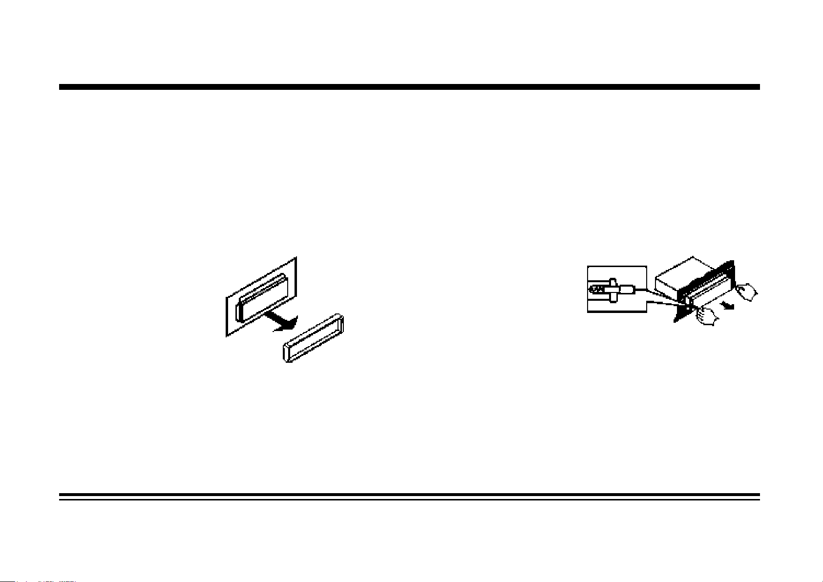
Remove the Old Unit from the Dashboard
1. Remove the outer trim frame.
DIN Front Mount
2. Insert the keys supplied with the
old unit into both sides of the unit
as shown in figure below until
they click. Pull to remove the old
unit from the dashboard.
DO NOT DISCONNECT WIRES
AT THIS TIME!
Mark Polarity of the Speaker Wires
Marking the polarity of the speaker wirers will make it easier to connect the existing speakers to your car radio. Consult wiring diagram
of existing head unit before disconnecting any wires. If you are not positive of the polarity of the existing wires from the speakers to the
head unit, install new wires.
1. While the old unit is playing, disconnect the wires from one speaker.
2. Take a length of masking tape and fold it around the wire so it forms a flag.
3. On the masking tape mark the polarity of the speaker wires (+&-), as well as left or right, and front or rear.
4. Double check that you marked the first speaker correctly by checking that the speaker wires are the same at the head unit.
5. Repeat this procedure for all of the speakers.
6. Mark the power, ground, and any other wires also.
Page 3
INSTALLATION
WARNING!
Disconnect negative battery terminal from battery before starting installation. Consult the vehicle’s owner’s
manual for proper instructions.
NOTE: Mark the polarity of the existing speaker wires before disconnecting battery.
NOTE: Remove the two transport screws from the top of the unit before installing.
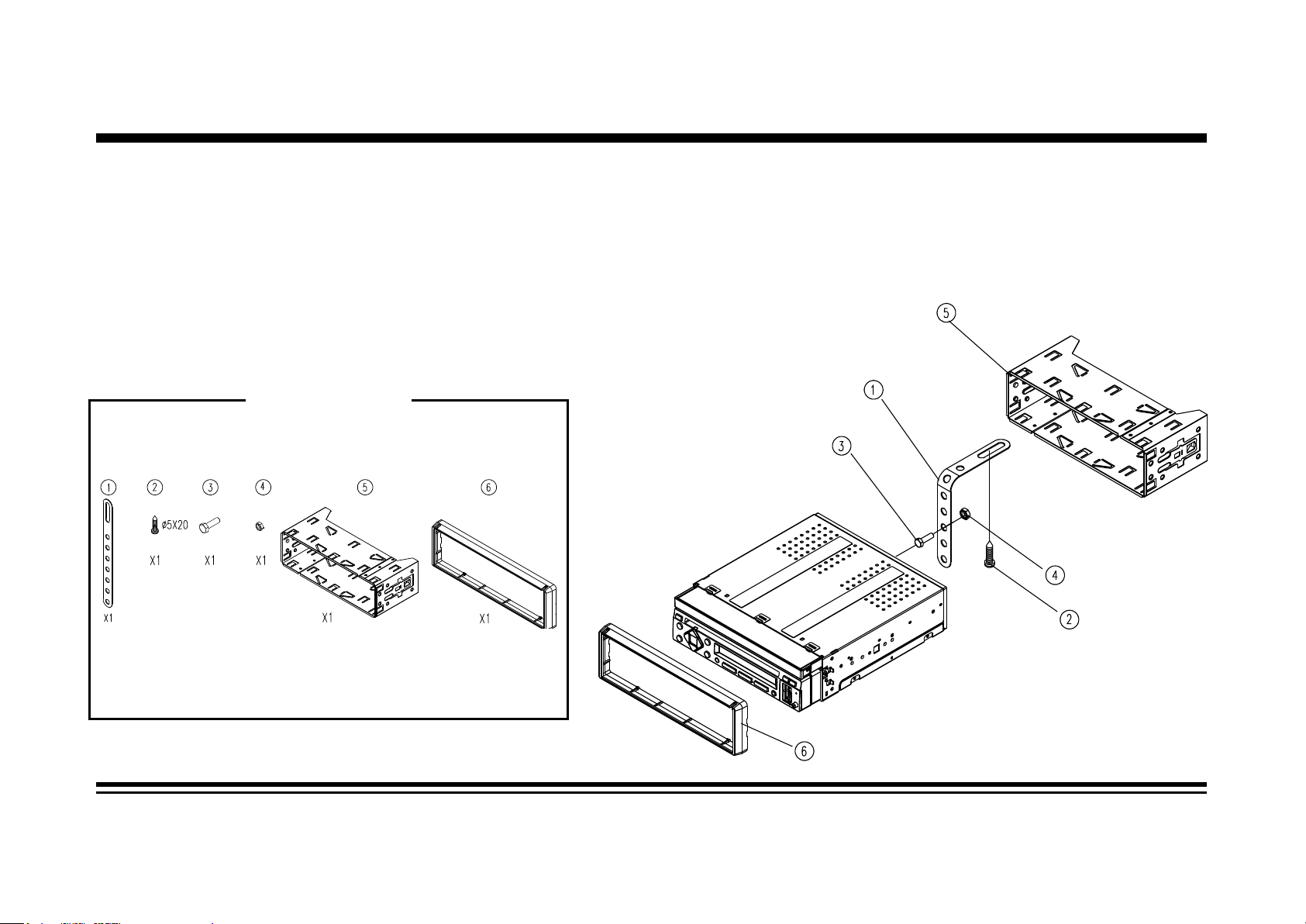
NOTE: Make sure there is enough space for the installation of this single-din in-dash.
SUPPLIED TOOLS
Page 4
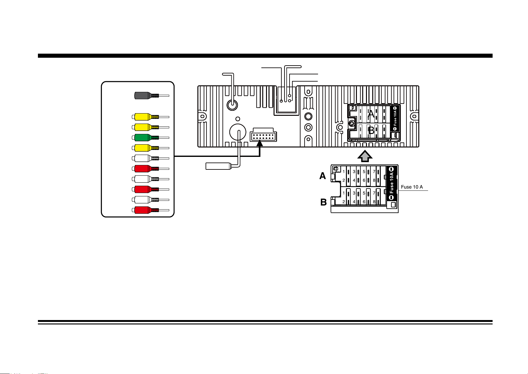
WIRING DIAGRAM
Amp power (+12V output-blue/white)
GPS Antenna
(RDN unit only)
Steering
wheel
control
(3.5mm jack)
BACK CAM
VIDEO OUT
SUB OUT
AUX VIDEO
AUX IN
(L)
AUX IN
(R)
RCA OUT
(F L)
RCA OUT
(F R)
RCA OUT
(R L)
RCA OUT
(R R)
Radio
Antenna
Connector A
1. Rear right speaker(+)/Purple
Rear right speaker(-)/Purple-Black
2.
3. Front right speaker(+)/Grey
4.
Front right speaker(-)/Grey-Black
5. Front left speaker(+)/White
6.
Front left speaker(-)/White-Black
7.
Rear left speaker(+)/Green
8.
Rear left speaker(-)/Green-Black
MIC
Parking (green)
Reverse(purple-white)
Connector B
1. -
2. -
3. -
4. Battery 12V (+)/Yellow
5. Antenna power/Blue-White
6. -
7. ACC+/Red
8. Ground/Black
Page 5

WIRING DIAGRAM
General Wiring Notes:
Make sure You have a good chassis ground. Good ground connection will eliminate most electrical noise problems. A good chassis
ground requires a tight connection to the .vehicle’s metal chassis. The area around the ground connection should be clean, bare metal
without rust, paint, plastic, dust, or dirt for a good ground connection.
Black Ground
Connect to vehicle body/chassis. Make sure you have a good chassis ground. This will eliminate most electrical noise form the motor
and alternator. A good chassis ground requires a tight connection to ground. The area should be free from rust, paint or any form of dirt.
Red Ignition
Connect to car ignition switch for main power supply of the unit.
Yellow Memory Backup
Connect to electrical terminal always supplied with power regardless of ignition switch position.
Blue-White Remote
Connect to Auto-antenna or power amp control wire/remote connection. Maximum current 300mA 12VDC. (Low Current)
Green (Hand Brake - Ground)
Connect this wire to the hand brake wire of your car so that the display will be on only when the car is fully stopped.
Purple-White (Rear Gear - VCC)
Connect this wire to the rear gear wire of your car so that the backup camera function
Various outputs (Refer to the wiring diagram)
Refer to the wiring diagram for the connection details.
can be activated when you car is in reverse gear.
Speaker Wiring Notes:
Follow the above wiring diagram to install the head unit with new or existing speakers.
1. This unit is designed for use with four (4) speakers with impedance between 4 Ohms to 8 Ohms.
2. An Impedance load of less than 4 Ohms could damage the unit.
3. Never bridge or combine the speaker wire outputs. When not using four speakers, use electrical tape to tape the ends of the unused
speaker outputs to prevent a short circuit.
4. Never ground the negative speaker terminals to chassis ground.
Page 6

Specifications
GENERAL
Operating Power...................................................................................................................12 Volts DC, Negative Ground
Output Wiring...........................................................................................................Designed for using four speakers only
RCA line out...............................................................................................................................low-level outputs - 1000MV
Output Impedance.........................................................................................................Compatible 4 to 8 Ohm Speakers
Fuses..........................................................................................................................................................................10 amp
Dimensions...................................................................................................................178mm(W) x 170mm(D) x 58mm (H)
Weight...........................................................................................................................................................................2.8 Kg
DVD/VIDEO/SYSTEM
Discs compatible...........................................................DVD, VCD 1.0/1.1/2.0/3.0, MP3, CD, CD-R, CD-RW, PICTURE-CD
Video System...........................................................................................................................................AUTO / PAL / NTSC
Mounting Angle......................................................................................................................................................0 to +/-30
TFT/SYSTEM
Resolution...............................................................................................................................................................800x480p
Brightness/Contrast..........................................................................................................................................270cd/m2, 450
Viewing angle......................................................................................................................................................................80
Response Time............................................................................................................................................Tr-30ms/Tf-10ms
Aspect Ratio.....................................................................................................................................................................4:3
FM/TUNER
Tuning Range......................................................................................... (USA) - 87.5 - 107.9MHz, (Europe) - 87.5 - 108 MHz
FM Sensitivity...............................................................................................................................................................12dBu
Stereo Separation @ 1 Khz...........................................................................................................................................35dB
AM/TUNER
Tuning Range.......................................................................................... (USA) -- 530-1710 KHz, (Europe) -- 522-1620 KHz
Am Sensitivity...............................................................................................................................................................30dBu
Page 7

BASIC OPERATIONBASIC OPERATION
1. Tuning the unit On / Off
Press the POWER button to turn the unit on. Press again to open/
close the monitor. Press and hold the POWER button to turn the
unit off.
2. Turning the TFT On / Off
On the main user interface, tap the daylight setting button on the
the top right corner of the monitor untilt he screen is off. Tap the
screen again to turn the TFT screen back on. Alternatively, press
and hold the MUT button on the front panel for this function.
3. Mode Selection
Press the MOD Button on the front panel to cycle the Play Mode
between RADIO, DISC, USB, SD, AV in and TV. Play mode can be
chosen by touching on the Main User Interface also.
4. Volume Control & Sound Select
Rotate the volume knob on the front panel to adjust the volume
level. Press the SEL button to cycle through BASS, TREBLE, BALANCE, FADER and rotate the volume knob to make corresponding
settings.
5. Eject button
When the monitor is open, press the EJECT button to adjust the
angle of the TFT monitor for better viewing experience. Press and
hold the EJECT button to eject CD or DVD.
6. Main User Interface
As shown on the diagram on the right. Each play mode can be accessed directly by touching the screen.
7. Motorised Tilt Screen
Press the EJECT button to tilt the screen in order to fit your viewing
angle. There are 4 steps up or down for angle adjustment
Page 8

Radio Operation
1. Choose Radio Band
Touch the AM button on screen to choose among the five radio bands - three FM Bands (FM1, FM2, and FM3) and two AM Bands (AM1,
and AM2). Each of the five bands can store up to six preset stations, for a total of 30 preset memory stations.
2. Radio Seek Function
In Radio Mode, touch and hold> or < Button to adjust the radio frequency automatically. Press the button once to adjust the radio frequency manually.
3. Save Your Preset Stations
There are six numbered preset buttons on the the screen (P1-P6) which can store and recall stations for each band. While listening to a
radio station you would like to save as a preset, touch and hold any key from P1-P6 until you hear a beep. The station will be saved in
the designated number.
4. Mute
Touch the mute button to mute the unit. Touch again to disable the mute.
5. Mono/Stereo Reception Control
In FM radio mode, touch the ST button to select stereo or mono reception.
Page 9

Radio Operation (Con’d)
6. Local/Distance Reception Control
In radio mode, touch the LOC button to select local or distance reception.
7. RDS Control (Optional)
AF, TA, PTY are the RDS functions. They are applicable to certain countries only. For countries when RDS is not available. The touch
sensitivity of the button will be disabled.
8. Returning to Main User Interface
Touch the ”BACK” button to return to the main user interface.
Page 10

DVD/VCD/CD Operation
1. Insert/Eject CD
Insert a disc into CD slot with label side up. The disc will be automatically loaded into the unit. The unit will display the opening screen
with loading status and the disc will play automatically. Press and hold the EJECT Button to eject the disc from the slot. If the disc is
not removed from the slot within 10 seconds, it will automatically be loaded into the slot again. When the disc is ejected and removed
(or not removed), the unit will automatically switch to radio mode.
2. Selecting Tracks
Press the SEEK >>| Button to advance to the next track. Track numbers will be shown on the display. Press SEEK >> to fast forward.
Press the SEEK |<< Button to go to a previous track. Track numbers will be shown on the display. Press the SEEK << Button to fast
reverse. Press >|| button, disc will play normally. On the Remote Control, use the |<< or >>| Buttons.
3. Control of DVD/CD functions
The control of DVD/CD functions is by the touch menu onscreen. The functions described below can be found in either way. To access
onscreen touch menu, touch the center of the screen and the menu will appear below. Touch the arrow button on the right to toggle
between the 3 pages of onscreen menu to adjust functions described below.
4. Audio Selection
Press the AUDIO button on the remote control, in order to choose the audio language. The audio languages available differ from
Disc to Disc. You can also use the setup menu to confirm. Refer to the packing of the Disc for details.
5. OSD (Display information)
Press the OSD button on the remote, so that the OSD will display on the monitor. Details such as title, track, playtime, etc, will be
shown.
6. Menu Playing (for DVD only)
Tap so that the menu of the disc will be prompted
7. Motion Picture Angle Adjustment
Press the picture angle adjustment key to adjust the angle of movie playing. This feature applies to specific DVD disc only.
8. Repeat Function
Press the Repeat button to toggle between repeat chapter, repeat title, repeat all and repeat off.
Page 11

DVD/VCD/CD Operation (Con’d)
9. Title Playing
Press the TITLE button so that the first title track of the DVD will be played.
10. Subtitle Selection
Press the Sub-T button to choose the sub-title you want. The sub-title languages available differ from Disc to Disc. You can also
use the setup menu to confirm. Refer to the packing of the Disc for details.
11. Track Search
Press the GOTO button to search the desired track to play the Disc. The OSD will be prompted. Make use of the navigation keys
and digit keys on the touch screen to choose your desired chapter, track. Press the ENTER button to confirm your selection.
Onscreen Menu
VOL
Eject
Disc
Random Zoom Angle View
Play/Pause
Audio
Selection
DVD Menu
Fast
Backward
Play Title
Rewind
Repeat
Track upStop Fast
Subtitle GO TO
Next PageTrack down
Next Page
Next Page
Page 12

DVD/VCD/CD Operation (Con’d)
12. Zoom +/-
Press the ZOOM button on the remote control to perform the zoom function. The zoom range is from 1/2 up to 4 (total 7 stages),
according to the zooming intensity.
13. Playing the DVD
After the disc is loaded, the movie of the DVD will be played automatically. The menu will be prompted so that you can choose the
setting. Press the MENU button during playback so that the menu will be shown.
14. Track Time Search
Press the GOTO button on the remote control to search the desired track time to play the Disc. The OSD will be prompted. Make
use of the navigation keys and digit keys on the remote control to choose your desired chapter, track or time. Press the ENTER
button to confirm your selection.
15. Video System
Press the BND/SYS button on the remote control to choose between NTSC, PAL, PAL60, AUTO, according to the encoding format
of the disc. The default mode is AUTO. Use this function if there is something wrong about the display function (eg. no color in
display).
16. Multi-Angle View
Press the ANGLE button on the remote control to perform multi-angle playback. The number of angles change in sequential order.
Note: The number of angles is different according to the disc. The function only work for discs having scenes recorded at different
angles. When no different angle is recorded, the OSD will show “INVALID KEY”
17. Programme Mode
Press the PROG button on the remote control to set the program play. Use the Navigation and Digit keys to set the Chapter and
Track no. as your desired sequence. Press Enter to begin the program play. Press the PROG button and confirm a blank program
again to cancel this operation.
18. Electronic Skip Protection
This unit is programmed with Electronic Shock Protection (ESP) so that the video will be protected against rough roads for 5
seconds.
19. Returning to Main User Interface
Press the arrow on the right hand side of onscreen menu to return to the main user interface.
Page 13

Bluetooth Operation
PAIRING
At BT mode, search bluetooth device by the phone and “RDD575BT Caliber” will appear in your phone. Input “0000” as password
to establish connection.
DIAL PAD
Touch the dial pad to dial the number you would like to call. Touch the CALL (green) button to send the number.
CALL RECORD
Press the HISTORY button to enter the phone book page to view received, missed and dialed calls. More details in the next page.
A2DP
Press the MUSIC button to enter the A2DP page to control playing music of your cellphone. More details in the next page.
REJECT CALL
Press the REJECT (red) button to end the call or to reject an incoming call.
RETURN TO USER MANUAL
Touch the arrow key on the top right corner to return to the main user interface.
Page 14

Bluetooth Operation (Con’d)
View Received Calls
Touch the RECEIVED CALLS button, the received calls will be displayed. There will be up/down arrows displayed for you to view t
hem one by one.
View Missed Calls
Touch the MISSED CALLS button, the missed calls will be displayed. There will be up/down arrows displayed for you to view them
one by one.
View Dialed Calls
Touch the DIALED CALLS button, the dialed calls will be displayed. There will be up/down arrows displayed for you to view them
one by one.
Playing Music on your cellphone
After activating music player in the cellphone, touch on screen to play or pause the music. Touch and to select up or down
one song in your song list.
Page 15

Settings
directly on the options or the arrows for up/down. Tap “BACK”
General Setting
The general setting menu includes wallpaper, logo, Key Beep, radio region, RDS region, aspect ratio, warning, calibration.
Time Setting
You can select Date, Time, Time mode and Time zone by tapping >
after the setting to take effect.
Page 16

Settings
GPS Setting (RDN only)
Enter the GPS setting to define the link of the execution file of your GPS program. Consult the installer if you are not familiar with the
setting. Tap OK after the full path is inserted. Now you can enter the Navigation mode in the OSD.
Make sure you have inserted the GPS map card properly (the lower micro SD card slot of the front panel) before the settings.
Language Setting
There are diferent languages to select.You can select the language you want for OSD, disc menu, disc audio and disc subtitle.
Page 17

Other Operations
1. GPS Navigation (RDN only)
If GPS navigation is available with the system, Tap the GPS logo on the OSD to enter GPS navigation. Follow the
on screen instruction to input destination and start navigation. The operation varies from software to software.
2. AV Input
The AV Input Jack is a set of composite input on the rear of the unit. Press the Mode button to choose AUX. Connect any portable audio/
video device such as a DVD player or VCD player to unit. Use the volume control to adjust volume.
3. Aux Input
The Aux Input Jack is a 3.5mm connector on the front panel of the unit. Press the Mode button to choose AUX. Connect any portable
audio device such as a discman or a portable MP3 player to the unit. Use the volume control to adjust volume.
4. Backup Camera Input
The backup camera input is on the back of the unit. (refer to wiring diagram). This input (in yellow) is for connecting backup camera for
parking. You must connect the VCC wire (in pink color) to the reverse gear switch in order to activate this video input mode when you
switch the reverse gear of your car. Please refer to the wiring diagram for more details.
5. Video Output x 1
The Video Output Jack is on the back of the unit. (Refer to Wiring Diagram) This output (in yellow) is for connecting monitor(s). You must
connect a monitor for car in order to play this unit in another monitor. Consult your dealer for any kinds of monitors that are
use in car.
6. RCA Output x 2 sets
The RCA Output Jack is on the back of the unit. (Refer to Wiring Diagram) This output is for connecting amplifier, equalizer, or other
audio component that requires a pre-amp out connection. (Red=Right, White=Left) Follow the manufactures instructions for the audio
component that you are connecting.
suitable to
7. Subwoofer Output x 1
The Subwoofer Output Jack is on the output wire harness. (Refer to Wiring Diagram) This output is for connecting up to 2 subwoofer
amplifier to the Subwoofer Output Jack to drive a subwoofer. Follow the amplifier’s installation instructions.
Page 18

INFRA RED REMOTE CONTROL
10
11
12
13
14
15
16
17
3
TITLE
ANGLE
VOL
SELECT
VOL
10
4
MUTE
SUB-T
SETUP
SLOW
ZOOM
SEEK
A
UDIO
3
4
GO TO
18
19
20
21
22
23
24
25
26
27
28
29
30
1
2
MOD
5
6
7
8
BAND
ENTER
9
ST
AMS
PROG
RPT
LOC
RDM
SEEK
PBC
OSD
1 2
5
6 7 8
9 0
1.Power on/off
2. Mode Select Key
3.Play / Pause Function
4.Mute Sound Function
5.Band Select
6/7/10/21.Cursor Button in Menu Mode
8.Confirm The Track/Chapter Selected
or Select Item In SETUP Menu
9. Stop Playback
11. Repeat Play Function
12.Program The Tracks To Be Played/Stereo Selection
13.Random Play Function
14/26. Track Up / Down or Fast Forward / Backward
15. PBC Play Mode
16. Statistical Disc Information Display Button
17. Number Select Key
18.Subtitle Language Switching Key
19. Show All Track's Title (DVD only)
20. Display SETUP Menu
22. Play DVD in Slow Advance
23. Watch The DVD Content From Different Angle
24. Zoom In and Zoom Out Function
25/29. Adjust Volume Level
27. Sound Select Button
28. Change The Audio Output Method
30. Track Time Serach
Page 19

MAINTENANCE
Cleaning the Unit
Do not use any liquids to clean this unit.
Do not use petroleum distillates to clean this unit.
Use a clean, dry cloth to clean this unit.
Replacing the Fuse
Make sure the amperage matches the specified value when replacing the fuse(s). If the fuse is bad, check the power connection and
replace the fuse with a new one. If the same problem occurs, this might indicate a malfunction within the unit.
Warning
When replacing a fuse, do not use a fuse with a higher amperage rating than the fuse originally supplied to your unit, otherwise damage will result to your unit.
Care of Discs
Do not use CDs with labels
Handle the disc by its edge
to keep the disc clean.
Do not touch the disc’s
surface.
or stickers attached. The
label may leave a sticky
residue when it begins to
peel.
Do not use a disc with
paste or ink residue on it.
Clean the discs with an
optional cleaning cloth.
Wipe each disc from the
centre out.
Page 20

WWW.CALIBER.NL
CALIBER HEAD OFFICE • The Netherlands • Fax: +31 (0)416 69 90 01 • E-mail: info@caliber.nl
 Loading...