

Page 1

L,OCƒAN
notice d,installation du systeme
owner,s manual for the system
betriebsanleitung des systems
www.cabasse.com
Page 2
f r a n c a i s
d e u t s c he n g l i s h
DEBALLAGE - UNPACKING - AUSPACKEN
Enlever l’insert vertical
Remove the vertical insert
Ziehen Sie das Sicherungsbrett heraus
Couper les 4 bandes de cerclage
Unstrap the crate
Zerschneiden Sie die vier Packbänder
Retirer le 1er niveau
Remove the upper quarter
Nehmen Sie den oberen Teil der
Transportverpackung ab
Retirer le couvercle
Remove the top board
Entfernen Sie den Deckel
Retirer ensemble la grille et sa mousse de protection.
ATTENTION à ne pas toucher le haut-parleur TC23
Remove together the front grill and its foam protection
ATTENTION: do not hit the TC23 driver when operating
Ziehen Sie den Grill zusammen mit seinem
Schaumformteil heraus
VORSICHT ! Berühren Sie beim Herausziehen
die Membranen nicht
Séparer la grille de la mousse de protection
Remove the grill from its foam shield
Entnehmen Sie den Grill aus seinem
Schaumformteil
Retirer le 2
ème
niveau
Remove the next quarter
Nehmen Sie den nächsten Teil der
Transportverpackung ab
Retirer le 3
ème
niveau
Remove the 3rd quarter
Nehmen Sie den vorletzten Teil der
Transportverpackung ab
Page 3
Enlever les vis de chaque coté de la rampe de
déchargement. Basculer la rampe
Remove the screws on each side of the
unloading pad. Swivel down the pad
Drehen Sie die Schrauben der Rampe heraus.
Klappen Sie die Rampe aus
Basculer l’enceinte d’un côté puis de l’autre afin de retirer les blocs de mousse
Tilt the loudspeaker from side to side to remove both foam blocks
Kippen Sie den Lautsprecher um die beiden Schaumblöcke zu entfernen
Enlever la mousse de protection
Remove the foam shield
Ziehen Sie das Schaumformteil heraus
Enlever la mousse de protection
Remove the foam shield
Ziehen Sie das Schaumformteil heraus
Décharger l’enceinte en la faisant rouler sur la rampe
Roll the loudspeaker down the pad
Ziehen Sie den Lautsprecher über die Rampe aus der Transportverpackung
ATTENTION !
- 2 personnes sont nécessaires pour effectuer le déballage.
- L’enceinte est protégée par une housse en tissu microfibre.
- Garder un jeu de bloc de mousse disponible pour le
remplacement des roulettes par les cone-vérins une fois les
enceintes proches de leur place finale.
ATTENTION !
- 2 persons minimum are required to unpack the
loudspeakers
- the loudspeaker is protected by a a microfiber cover
- keep a set of foam blocks available for the replacement of
the wheels by the cones.
ACHTUNG !
- Zum Aus- und Einpacken sind zwei Personen notwendig
- Die Lautsprecher sind mit einer Schutzhaube versehen
- Zum Anschrauben der Kegelfüße werden beide
Schaumblöcke benötigt
Page 4
ASSIGN
Left Right
ASSIGN
Left Right
ASSIGN
Left Right
ASSIGN
Left Right
f r a n c a i s
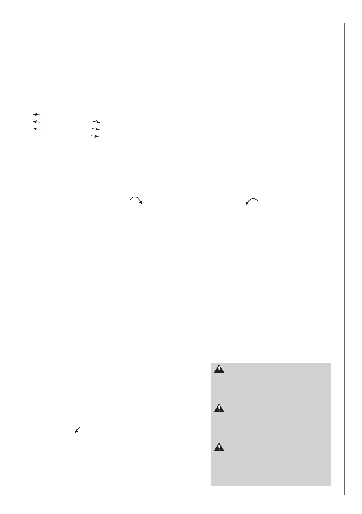
ABNEHMEN DER TRANSPORTROLLEN UND ANSCHRAUBEN DER KEGELFÜSSE
d e u t s c he n g l i s h
DEMONTAGE DES ROULETTES ET MONTAGE DES CÔNES-VERINS
REPLACEMENT OF THE DELIVERY CASTORS BY THE CONES
A1 A5
B
10
B
11
ASSIGN
Left Right
A4 A2 A3
ASSIGN
Left Right
A1
B
12
B
B
B
7
8
9
B
B6B
4
5
B
2
A5
A4A2A3
B
1
Page 5

ASSIGN
Left Right
2a 3
1
2b
3
1
7
4
5
1
6
9
SELECT + OK
SELECTION + CONFIRMATION
AUSWÄHLEN + BESTÄTIGEN
2a
5
4
POWER ON/OFF
MARCHE/ARRET
EINSCHALTEN / AUSSCHALTEN
2b
STAND BY ON/OFF
MISE EN VEILLE / SORTIE DE VEILLE
STAND-BY / BETRIEB
3
VOLUME
DISPLAY
8
FUNCTION
6
FONCTION
FUNKTION
7
MUTE
4
SCROLL RIGHT + DOWN
DEFILEMENT DROIT + BAS
RECHTS + ABWÄRTS
5
SCROLL LEFT + UP
DEFILEMENT GAUCHE + HAUT
LINKS + AUFWÄRTS
6
VOLUME CONTROL
REGLAGE DU VOLUME
LAUTSTÄRKEREGLER
7
MUTE ON / MUTE OFF
COUPURE / RESTAURATION DU SON
STUMMSCHALTUNG (MUTE)
8
DAP DISPLAY SETTING
REGLAGE DE LA LUMINOSITE DE L’ECRAN DU DAP
DIMM-FUNKTION DISPLAY
9
HEADPHONE SOCKET
PRISE CASQUE
KOPFHÖRERANSCHLUSS
Page 6
77
77
78
78
79
No
No
No
No
No
No
No
No No
Yes Yes
Yes
Yes
Yes
Yes
Yes
f r a n c a i s
A-POSITIONS DE MESURE DANS UNE PIECE DE FORME RECTANGULAIRE
MEASUREMENT POINTS IN A RECTANGULAR ROOM
MESSPOSITIONEN FÜR DAS MIKROFON IN EINEM RECHTECKIGEN RAUM
d e u t s c he n g l i s h
P0
P3
LISTENING AREA
B- RECOMMANDATIONS POUR LES POSITIONS DE MESURE P4 ET P5
P4 AND P5 MICROPHONE’S POSITIONS
P4 UND P5 MESSPOSITIONEN
No
No
Yes
No
Yes Yes
No
Yes
Yes
No
P1 P2
P5
P4
No No
No
Yes
Yes
No
Yes
No
Positions recommandées du microphone
Yes
Recommended positions for the microphone
Richtige Mikrofonposition
Positions du microphone déconseillées
No
Microphone positions to be avoided
Falsche Mikrofonposition
No
Yes
No
Yes
Zone d'écoute
Listening area
Hörplatz
No
No
Page 7
f r a n c a i s
Vous venez d’acheter des enceintes Cabasse et nous vous remercions de votre confiance.
Dans le but d’optimiser au maximum votre installation, nous vous recommandons
de lire attentivement cette notice.
INSTRUCTIONS DE SECURITE
Explication des symboles -
L’éclair dans un triangle
équilatéral avertit de l’existence de tension élevée dangereuse non isolée à l’intérieur du
coffret du produit, d’une valeur
suffisante pour présenter un risque d’électrocution.
Le point d’exclamation dans un triangle équilatéral
avertit de l’existence d’instructions importantes quant à
l’utilisation et la maintenance dans la documentation jointe à
ce produit.
Instructions - Toutes les instructions de sécurité et d’utilisa-
tion doivent avoir été lues avant d’allumer tout appareil pour
la première fois.
Retenez les instructions - Elles doivent servir de référence
permanente pour tout ce qui suit.
Tenez compte des avertissements - Les avertissements
présents sur le produit ou dans les notices d’utilisation doivent
être pris en compte.
Suivez les instructions -
et de mise en oeuvre doivent être scrupuleusement suivies.
Toutes les instructions d’utilisation
Nettoyage - Débranchez l’appareil avant tout nettoyage.
N’utilisez pas de solutions nettoyantes sous forme liquide ou
en aérosols. Employez de préférence un chiffon humide.
Accessoires - N’utilisez pas d’accessoires qui ne soient pas
explicitement recommandés par le constructeur, sous peine de
risquer divers accidents.
Eau et humidité - L’appareil ne doit pas être utilisé près de
l’eau, par exemple à proximité d’une baignoire, d’un évier, dans
un sous-sol humide, près d’une piscine, ou de tout ce qui y
ressemble de près ou de loin.
Chariots et supports - La manutention doit
être effectuée seulement avec des chariots et supports agréés par le fabricant.
> Attention aux chariots de manutention
Installation sur mobiliers et supports - Ne placez pas
cet appareil sur un support instable, qu’il s’agisse de pieds,
trépieds, tables, étagères, etc. Il pourrait tomber et causer des
blessures sérieuses à un enfant ou un adulte qui se trouverait
à proximité.
Ventilations - L’appareil doit être positionné de telle sorte
qu’il ne gêne pas sa propre ventilation. Par exemple, il ne doit
pas être installé sur un lit, un canapé, une couverture ou des
surfaces similaires qui pourraient bloquer ses orifices d’aération. Il ne doit pas non plus être encastré dans des enceintes
confinées comme des étagères étroites ou des meubles qui
pourraient limiter la quantité d’air disponible aux entrées
d’air.
Alimentation - L’appareil ne doit être relié qu’à une source
électrique du type écrit dans le mode d’emploi ou conforme à
la sérigraphie sur le produit. Si vous n’êtes pas sûr du type de
courant fourni à l’endroit où vous vous trouvez, adressez-vous
à votre revendeur ou à la compagnie électrique locale.
Sacs plastiques - Ne pas laisser les sacs plastiques de l’em-
ballage à portée des enfants afin d’éviter tout risque d’étouffement.
Protection des câbles d’alimentation - Le cheminement
des câbles d’alimentation doit être prévu de telle sorte qu’ils ne
puissent pas être piétinés, pincés, coincés par d’autres appareils posés dessus, et une attention toute particulière doit être
accordée à l’adéquation des prises et à la liaison du cordon
avec l’appareil.
Foudre - Pour une meilleure protection de l’appareil pendant
les orages ou s’il doit rester inutilisé pendant une longue période, débranchez le cordon d’alimentation et débranchez la
prise d’antenne, vous éviterez ainsi les risques de détérioration
dus à la foudre ou aux surtensions.
Surcharges électriques - Ne surchargez pas les prises d’ali-
mentation, les prolongateurs ou les rappels d’alimentation. Il
pourrait en résulter incendies ou électrocutions.
Corps et liquides étrangers - On doit être attentif à ne
jamais laisser entrer d’éléments ou de liquides étrangers dans
l’appareil. Ne jamais poser d’objet rempli de liquide tel qu’un
vase sur ou à côté de tout appareil. Ils pourraient occasionner incendies ou électrocutions. Ne versez jamais aucun liquide
d’aucune sorte sur l’appareil. Ne jamais placer d’objets enflammés tels des bougies allumées sur ou à côté des appareils.
Entretien - L’utilisateur ne doit pas tenter de s’occuper des
opérations de maintenance au-delà de celles décrites dans le
mode d’emploi. Tout ce qui dépasse le simple niveau de l’entretien doit être effectué par un personnel qualifié.
Maintenance - Dans les cas suivants, vous devez impérative-
ment débrancher votre appareil et le faire vérifier par un technicien qualifié :
l’alimentation ou la prise a été endommagée.
des corps étrangers ou du liquide se sont introduits dans l’ap-
pareil.
l’appareil a été exposé à la pluie ou a été aspergé d’eau.
l’appareil ne semble pas marcher correctement alors que vous
l’utilisez dans le cadre de ses instructions de fonctionnement
normal. Ne manipulez que les contrôles couverts par le mode
d’emploi. Toute autre procédure pourrait le détériorer et né-
cessiter l’intervention d’un technicien qualifié.
l’appareil est tombé ou bien sa carrosserie est endommagée.
l’appareil affiche des performances nettement modifiées.
Pièces détachées - Si la réparation a nécessité l’utilisation
de pièces détachées, assurez-vous que le technicien a bien utilisé les références préconisées par le fabricant ou présentant les
mêmes caractéristiques que les pièces originales. Des pièces
non conformes peuvent provoquer incendies, électrocutions
ou autres.
Vérifications - Après toute intervention sur l’appareil, de-
mandez au technicien d’effectuer des tests afin de garantir que
l’appareil fonctionne en toute sécurité.
Exposition aux fortes températures - L’appareil doit être
tenu éloigné de sources de chaleur comme radiateurs, chauffage divers, amplificateurs, ou tous autres éléments susceptibles de le placer dans des conditions de températures anormalement élevées.
Valable aux USA, au Canada et autres pays concernés
Attention ! pour éviter les chocs électriques, introduire la lame
la plus large de la fiche dans la borne correspondante et pousser
jusqu’au fond.
Page 8
f r a n c a i s
SYSTEME L’OCÉAN
DEBALLAGE DU SYSTEME (pages 2 et 3)
Le système L’Océan est livré dans 3 emballages:
2 x caisses bois contenant les enceintes
1 x carton contenant: le préamplificateur DAP ( Digital Adaptive
Preamplifier = Préamplificateur Numérique avec Adaptation au
local), sa télécommande, 2 piles AAA, 6 cônes-vérin, une clé
hexagonale pour le démontage des roulettes, une tige pour
l’ajustement en hauteur des cônes vérins, 2 câbles secteur classe
I, 1 câble secteur classe II, 2 câbles optiques de 10 m, 1 microphone de mesure et son support, 1 notice, 1 carte de garantie,
une paire de gants et un chiffon microfibre.
ATTENTION : étant donné le poids élevé de ces enceintes, 2
personnes sont nécessaires pour effectuer le déballage.
Déballage des enceintes : suivre scrupuleusement les instructions des
pages 2 et 3, puis reconstituer les emballages vides en y mettant tous les
accessoires de calage et de protection avant de les entreposer dans un
endroit sec pour un usage ultérieur.
Déballage du carton : ouvrir le coté mentionné sur le carton, replier sur
les côtes les rabats supérieurs, enlever la plaque contenant les accessoires
pour accéder à l’emballage du DAP. Vérifier que le contenu correspond à
la liste ci-dessus.
Les emballages doivent être conservés pendant toute la durée de la garantie.
POSITIONNEMENT ET PLACEMENT
DES ENCEINTES ACOUSTIQUES
Positionnement des enceintes
Les enceintes l’Océan sont livrées avec des cônes de découplage
(page 4). Ces cônes de découplage permettent d’assurer une
meilleure stabilité de l’enceinte tout en limitant les résonances
pouvant être générées par certains types de sols comme les planchers par exemple. Leur hauteur est ajustable après avoir desserré
le contre-écrou. Bien resserrer les contre-écrous une fois l’enceinte stabilisée.
ATTENTION : les enceintes L’Océan doivent absolument
reposer sur leurs cônes-vérins ou sur leurs roulettes de
transport afin de garantir la bonne ventilation de l’électronique
embarquée. Toute utilisation sans ces accessoires annule toute
possibilité d’application éventuelle de toute garantie.
Les enceintes sont livrées avec un cône de protection en face
avant. II est possible de les utiliser sans ce cadre. Enlevez le cadre
en exerçant une légère traction horizontale sur sa partie supérieure
pour rompre sa liaison magnétique avec l’ébénisterie de votre enceinte. Pour remettre le cadre en place, présentez le devant la face
avant de l’enceinte et approcher doucement le cadre et le tourner
jusqu’à ce que les liaisons magnétiques soient établies.
Procédez à ces opérations délicatement pour éviter une usure prématurée de la partie du revêtement couvrant les aimants insérés
sur la face avant de l’ébénisterie.
Le champ magnétique des moteurs des haut-parleurs va rayonner au-delà de l’enveloppe de l’enceinte acoustique. Il faut donc
éloigner d’environ 50 cm les appareils et objets sensibles à ce type
de rayonnement (téléviseurs et écrans d’ordinateur type CRT,
disquettes informatiques, bandes magnétiques audio ou vidéo,
cartes à puces…).
Placement des enceintes dans une pièce
Outre la position des enceintes, il faut tenir compte de leur emplacement dans la pièce, les propriétés acoustiques d’un local
étant un facteur capital dans la retransmission du son.
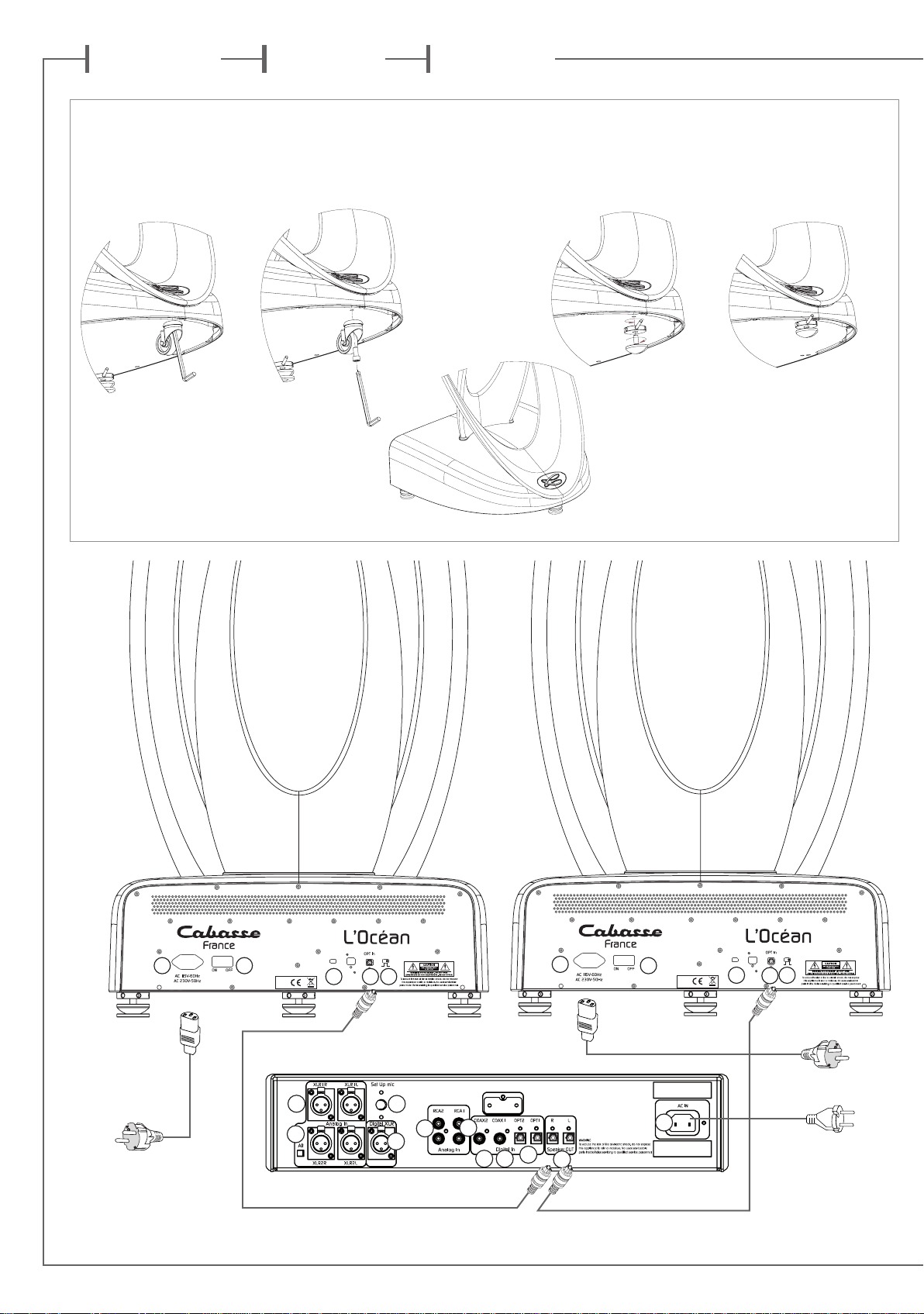
Le placement optimal
pour une écoute stéréo classique 2.0 (page 6)
Si l’on considère que d est la distance qui sépare les deux en-
ceintes, celle-ci doit être supérieure à 1,5 m. Les deux enceintes
doivent être à égale distance de la zone d’écoute qui forme avec
elles un triangle équilatéral.
Les haut-parleurs doivent être dirigés vers la zone d’écoute.
Les enceintes doivent, de préférence, diffuser dans le sens de la
plus grande dimension de la pièce.
D’une façon générale, on doit éviter de positionner les enceintes
dans les coins d’une pièce, car la disposition en angle favorise
les fréquences graves. De même, les enceintes doivent se situer à
une distance d’au moins 20 cm du mur.
Pour une bonne ventilation de l’électronique embarquée, tou-
jours laisser un espace d’au moins 10 cm entre l’arrière de l’enceinte et toute paroi, cloison mobile, meuble ou rideau.
Aucun élément (table, fauteuil…) ne doit gêner la propagation
directe entre les enceintes et l’auditeur. Un effet de masque,
même partiel, déséquilibre complètement la reproduction sonore car il provoque une atténuation des fréquences aiguës et
dans la majorité des cas des médiums également.
La disposition des enceintes dans des niches est à proscrire car
elle modifie la courbe de réponse de l’enceinte et gène la bonne
circulation d’air nécessaire à la ventilation de l’électronique embarquée.
ATTENTION : Avant tout branchement, s’assurer que
votre tension secteur correspond bien à la tension secteur
annoncée sur l’emballage, la fiche de garantie, le socle de
l’enceinte. Si ce n’est pas le cas, suivre les instructions du
§ ALIMENTATION SECTEUR.
CONNEXION DES ENCEINTES AU DAP (page 4)
Connecter les 2 câbles optiques fournis (ou des modèles équivalents
de longueur appropriée) entre les sorties «Speaker OUT»
et les entrées «OPT In»
Positionner le sélecteur «ASSIGN» (A3) sur Right pour l’enceinte
droite et sur Left pour l’enceinte gauche. Vérifier que l’interrupteur
(A4) est enfoncé en position «on»: il permet l’activation de l’éclairage des logos bleus indiquant que les enceintes sont opérationelles.
A2
des enceintes.
ATTENTION : Pour ne pas altérer la qualité de la
transmission, ne pas plier les cables de liaison au delà de l’angle
de courbure maximum sans contrainte du câble. Le rayon de
courbure du câble optique ne doit jamais être inférieur à 5 fois
le diamètre du câble. Les extrémités du câble optique doivent être
parfaitement propres. Si besoin utiliser un produit type alcool
isopropylique.
B
2
du DAP
ALIMENTATION SECTEUR (page 4)
a) Alimentation des enceintes
La prise
Vérifiez la tension d’alimentation indiquée près de cette prise.
A1
sert à alimenter l’électronique de l’enceinte L’océan.
Page 9
Si elle ne correspond pas avec la tension de votre circuit électrique, contacter votre revendeur/installateur agréé qui fera les
modifications nécessaires.
Chaque enceinte doit être reliée à une prise secteur munie d’une
connection à la terre et capable de délivrer 12 A.
b) Alimentation du préamplificateur DAP
B
La prise
automatiquement à tout voltage de 100 à 240 V.
1
sert à alimenter le processeur. L’alimentation s’adapte
ATTENTION : Les interrupteurs d’alimentation du
préamplificateur DAP et des enceintes L’Océan doivent toujours
demeurer aisément accessibles.
UTILISATION DES COMMANDES EN FAÇADE
DU DAP ET SUR LA TELECOMMANDE
Toutes les fonctions du système L’Océan sont accessibles par les
commandes en façade du préamplificateur DAP et sur la télécommande, exceptées les commandes marche/arrêt (2A), veille (2B)
et affichage (8). L’activation de la télécommande par pression
d’une de ses touches est confirmée par l’illumination de l’anneau
bleu autour de la touche «
réitérer la commande. Remplacer les piles si nécessaire.
1
PUSH ENTER et
Un bref appui sur cette touche permet de sélectionner la proposition sur fond clair au menu de l’écran du DAP.
2
MISE EN ROUTE, VEILLE, ARRET DU SYS-
» . A défaut de cette lumière bleue,
TEME
MARCHE: appuyer sur l’interrupteur
en route. Le bouton reste enfoncé et est éclairé avec une lumière
bleue. Le premier écran figurant sur la page 10 apparaît au bout
de plusieurs secondes ce qui confirme l’initialisation du système,
les interrupteurs on/off des enceintes étant sur «on». Les logos
sur les socles des enceintes s’illuminent si les interrupteurs
sont enclenchés.
VEILLE: le bouton
du système, le voyant clignote alors en rouge, l’écran est éteint
et les logos des enceintes s’éteignent. Presser une nouvelle fois le
bouton
ARRÊT: appuyer sur l’interrupteur
saillant pour une déconnexion complète du DAP avec le réseau
électrique. Positionner les interrupteurs
ceintes sur «off» pour les déconnecter du réseau électrique.
Cette touche permet d’ouvrir le menu comme de sortir de chaque
page du menu. En l’absence de validation, sélection ou déplacement du curseur dans le menu au bout de 8 secondes, la dernière
option confirmée par un OK reste valide et la page précédente
s’affiche. Les réglages CRCS et de tonalité sont par contre activés
et validés dès leur sélection avec le curseur.
SELECTION DES ENTREES: une simple rotation dans un sens ou
dans l’autre fait défiler les entrées prêtes à fournir un signal audio.
L’entrée à l’écran devient l’entrée active.
SELECTIONS DANS LE MENU: une fois le menu ouvert avec la
touche FUNCTION, une rotation vers la droite de la molette de
la télécommande ou du bouton SELECT permet de déplacer le
curseur vers la droite ou le bas. Une rotation vers la gauche mène
le curseur vers le haut ou vers la gauche.
2b
3
FUNCTION
4
5
et
2b
de la télécommande permet la mise en veille
pour sortir du mode veille.
SELECT
2a
du DAP pour la mise
2a
de façon à ce qu’il soit
a5
situés derrière les en-
a4
6
REGLAGE DU VOLUME
Le volume est réglable de -90 dB à 0 dB. il est indiqué à titre
indicatif, le niveau sonore final variant suivant les sources et
les enregistrements, la distance d’écoute et l’amplitude des réglages CRCS et de tonalité.
Pour augmenter le volume: tourner le bouton VOLUME du DAB
vers la droite ou appuyer sur la touche «+» de la télécommande
Pour diminuer le volume: tourner le bouton VOLUME du DAB
vers la gauche ou appuyer sur la touche «-» de la télécommande
7
MUTE
Une simple pression sur cette touche permet d’abaisser le volume automatiquement au niveau sélectionné dans le menu:
soit une suppression totale du son avec la position «- ∞ dB»,
soit une baisse de 50 dB ou de 20 dB. «Mute» s’affiche alors à
l’écran. Une seconde pression sur «MUTE» positionne le potentiomètre de volume à sa valeur précédente.
8
DISPLAY
Cette touche de la télécommande permet de choisir par pressions successives entre 3 modes d’affichage: contraste maximum, contraste moyen, écran noir.
9
PRISE CASQUE
Cette prise en façade du DAP permet d’utiliser un casque stéréophonique. Les sorties enceintes sont coupées dès la connection du casque. Le volume sonore dans le casque s’ajuste avec
les commandes
casque est débranché, les sorties enceintes sont réactivées avec
le réglage de volume initial.
6
du DAP et de la télécommande. Dès que le
ATTENTION : L’écoute à fort niveau sonore avec des
écouteurs ou casques audio peut entraîner une dégradation
temporaire voire une perte intégrale des capacités auditives.
RACCORDEMENT DES SOURCES AUDIO
Le DAP Cabasse est équipé d’un système automatique de détection des sources audio. Il suffit de raccorder chacune de vos
sources via le type de connexion choisie et de les activer pour
que les entrées connectées s’affichent à l’écran. Utiliser alors le
mode SELECT pour choisir la source à écouter.
Voici les entrées disponibles (dessin page 4)
5 ENTREES NUMERIQUES:
B
3
B
4
+
: entrées numériques optiques OPT1 et OPT2
B
5
B
6
+
: entrées numériques coaxiales COAX1 et COAX2
B
7
: entrée numérique XLR AES/EBU
4 ENTREES ANALOGIQUES:
B
8
B
9
+
: entrées analogiques RCA1 et RCA2
B
10
B
11
+
: entrées analogiques symétriques XLR1 et XLR2
Attention à ce que les sorties analogiques droite et gauche de la
source soit bien connectées aux entrées correspondantes droite
(R) et gauche (L)du DAP.
B
L’entrée XLR2
cas de connexion à une source à tension de sortie élevée.
NOTE: la prise
ment du microphone de mesure pour la calibration SCS. Ne
connecter aucun autre appareil à cette prise.
11
est équipée d’un atténuateur (Att) à utiliser en
B
12
ne peux être utilisée que pour le branche-
Page 10

f r a n c a i s
MISE EN ROUTE ET UTILISATION DU SYSTÈME
1. Mettre les interrupteurs des 2 enceintes L’Océan sur «on».
Mettre en route le préampli DAP par pression sur le bouton « »
du DAP: les figures de Lissajous
sur la base des enceintes
s’illuminent, le système est prêt à fonctionner sans activation du
système CRCS.
2. Mettre en marche la source désirée. Elle sera automatiquement sélectionnée.
3. Si plusieurs sources sont activées, tourner le bouton
«SELECT» du DAP ou la molette circulaire de la télécommande
jusqu’à ce que la source désirée s’affiche.
4. Pas de source connectée : brancher et activer une source.
5. La source précédemment utilisée n’est plus détectée: activer
cette source.
6. Ajuster le volume sonore en tournant le potentiomètre
«VOLUME» ou en pressant les touches VOLUME «+» et «-» de
la télécommande.
MISE EN SERVICE DU SYSTEME CABASSE DE CORRECTION DE SALLE (CRCS)
1. Sélectionner CRCS dans le menu obtenu après avoir appuyé
sur le bouton «FUNCTION» (fonction) du DAP ou de la télécommande.
2. Presser le bouton «SELECT» (figure de Lissajou sur la télécommande) pour confirmer le lancement du protocole de mesures.
3. Connecter le microphone livré avec le DAP dans la prise jack
(«Set Up mic»
4. Mesurer la distance séparant les tweeters de chaque enceinte, sélectionner la bonne valeur en faisant tourner le bouton
«SELECT» puis valider en poussant le même bouton.
B
12
au dos du préamplificateur.
5. Démarrage du protocole de mesures: voir les schémas page 6 :
les positions de mesure du microphone.
ère
6. 1
mesure: positionner le microphone à 1 mètre du tweeter
de l’enceinte de droite puis valider avec
1
. Cette mesure détermine le niveau sonore nécessaire aux mesures suivantes. Noter
que les commandes de contrôle de volume sont désactivées
pendant toute la séquence de mesures CRCS.
7. SILENCE! La première séquence commence par une mesure
du bruit ambiant, puis par la détermination du volume sonore
nécessaire aux mesures suivantes.
Page 11

8. MESSAGE D’ERREUR : Le rapport signal/bruit est insuffisant
pour faire une mesure correcte: vérifier que l’enceinte émet bien
un signal. Si oui, établir le silence dans la pièce et recommencer
les mesures en appuyant sur «SELECT» . Si pas de signal, vérifier
toutes les connexions (micro, liaison DAP-enceintes) et recommencer la procédure.
9. Valider la poursuite du protocole si les conditions de la première mesure semblent satisfaisantes. Si par exemple la première mesure a été perturbée, selectionner «retry» (nouvel essai)
et valider. La position «cancel»(annulation) permet de sortir du
protocole.
10. Placer le microphone en position P1, soit à la position
d’écoute à égale distance des 2 tweeters et à hauteur de l’oreille
de l’auditeur en P1. Valider avec
1
.
15. Placer le microphone en position P4: proche du mur arrière, à
une hauteur représentant les 2/3 de celle de la pièce, soit 1,70 m
pour un plafond à 2,50 m du sol.
16. Placer le microphone en position P5: proche d’un mur latéral, à une hauteur représentant les 2/3 de celle de la pièce.
Confirmer la mesure puis valider «Continue» pour passer à
l’étape suivante.
17. Valider les mesures effectuées en P5
18. Les 5 séries de mesures ont été effectuées. Valider en pressant le bouton «SELECT».
11. La deuxième série de mesures est en cours. Une première
mesure du signal émis par l’enceinte de droite sera effectuée,
puis le signal sera émis de l’enceinte de gauche.
12. Valider la poursuite du protocole si les conditions de mesure
semblent satisfaisantes.
13. Placer le microphone en position P2, à la seconde position
d’écoute. Si la position d’écoute est unique placer le microphone légérement à droite, 30 cm au dessus et 30 cm derrière
P1. Confirmer le lancement de la mesure puis valider «Continue» pour passer à l’étape suivante.
14. Placer le microphone en position P3, à la 3ème positon
d’écoute. Si la position d’écoute est unique, placer le microphone légérement à gauche, 30 cm au dessous et 60 cm derrière
P1. Confirmer la mesure puis valider «Continue» pour passer à
l’étape suivante.
19. Le CRCS analyse les mesures et calculent les corrections à
apporter pour corriger les anomalies acoustiques de la pièce.
20. MESSAGE D’ERREUR: le CRCS a relevé une incohérence
dans les mesures et n’a pu calculer les distances tweeter-microphone pour chaque point de mesure. Valider l’annulation et recommencer le protocole en 1.
21. La phase de calculs se termine. Cette étape peut durer plusieurs minutes.
22. La dernière session de réglage permet un réglage fin du système. Utliser votre source et vos morceaux préférés, avec par
exemple le SACD/CD Cabasse si une de ces sources est le plus
utilisée.
Page 12

f r a n c a i s
23. Valider le démarrage de cette dernière phase de mesure.
Noter qu’il est possible de revenir ultérieurement directement à
cette étape d’ajustement de l’équilibre spectral au fur et à mesure des écoutes. Valider alors le réglage ci-dessous à 0dB.
24. Tester différents réglages de la pente de la courbe de réponse entre +4 dB et -6dB. Dans la majorité des cas le réglage
final ne comprend pas de correction supérieure à + 1 dB.
25. Le protocole CRCS s’est déroulé avec succès.
26. La figure de Lissajou en haut à droite de l’écran signifie que
le module CRCS est actif. Elle figurera dorénavant sur tous les
écrans.
27. Sélectionner «Back» et valider en pressant le bouton «SELECT» pour sortir du menu CRCS. Débrancher le microphone.
Le système CRCS est opérationel.
DESACTIVATION / ACTIVATION DU CRCS
1. Sélectionner «PRESET» (préréglages) dans le menu obtenu
après avoir appuyé sur le bouton «FUNCTION» (fonction) du
DAP ou de la télécommande. Valider, sélectionner «CRCS» puis
valider.
MODIFICATION DE L’EQUILIBRE SPECTRAL
1. Pour affiner les réglages d’équilibre spectral sans devoir refaire
les mesures avec le microphone, sélectionner «PRESET» (préréglages) dans le menu obtenu après avoir appuyer sur le bouton
«FUNCTION» (fonction) du DAP ou de la télécommande.
2. Choisir «off» et valider.
3. Suivre la procédure analogue pour réactiver le CRCS avec les
paramètres en mémoire: PRESET + CRCS+On.
3. Valider «on».
2. Sélectionner «CRCS».
4. Comparer différentes valeurs avec des plages musicales de
référence. Valider avec 1 la valeur retenue.
Page 13

CORRECTEURS DE TONALITE / MODE DIRECT
1. En sus du CRCS, le DAP est pourvu de correcteurs de tonalité classiques graves et aigus. Il permet notamment de corriger
l’équilibre spectral de certaines sources. Pour que ses ajustements soient effectifs le mode «Direct» doit être réglé sur «Off».
2. Pour actionner la correction du niveau d’aigus, sélectionner
«Preset» puis «Treble»,, valider et choisir l’intensité de la correction entre 11 positions de - 5 dB à + 5 dB.
REGLAGES PERSONNALISES
REGLAGE D’INTENSITE DU MUTE (baisse de volume instantanée)
3. Pour actionner la correction du niveau de graves, sélectionner
«Bass» puis choisir l’intensité de la correction entre 11 positions
de -5 dB à + 5 dB.
4. Pour les sources ne nécessitant pas de corrections autres
que le CRCS, activer le mode «Direct» en le réglant sur «on».
«Direct» reste alors affiché à l’écran. Les réglages graves/aigus
restent en mémoire et seront activés des que le mode «Direct»
est de nouveau inactif («Off»).
1. Sélectionner «User» et «Mute» après avoir accédé au menu
par la touche «FUNCTION».
2. Choisir l’option désirée: la position par défaut est «- ∞ dB»,
soit l’extinction complète du signal. Les 2 autres options diminuent le volume sonore au moment de l’activation du mute soit
de 20 dB, soit de 50 dB.
REGLAGE DU MODE VEILLE AUTOMATIQUE (Automatic Power off)
1. Sélectionner «User» après avoir accédé au menu par la
touche «FUNCTION».
3. La fonction Mute s’active en pressant le bouton «Mute» du
DAP ou de la télécommande. «Mute» s’affiche alors sur l’écran
du DAP.
4. Une seconde pression sur le bouton «Mute» désactive la fonction et positionne le contrôle de volume au réglage précédent.
Toute action sur un des contrôles de volume désactive également le mode «Mute».
3. En sélectionnant une des trois autres options, le DAP et les
enceintes seront automatiquement mises en stand-by après 10,
15 ou 20 minutes d’absence de signal de la source sélectionnée.
2. Le mode mise en veille automatique est par défaut désactivé
avec l’option «Never».
Page 14

f r a n c a i s
PERSONNALISATION DU NOM DES SOURCES
1. Sélectionner «User» après avoir accédé au menu par la touche
«FUNCTION».
2. Sélectionner «Input» pour accéder à la liste des entrées.
3. Valider le choix de l’entrée.
4. Positionner le curseur sur le caractère à modifier en tournant
le bouton «SELECT». Valider en pressant le bouton «SELECT».
5. Choisir le nouveau caractère (lettre minuscule, lettre
majuscule ou chiffre) par rotation de la commande
«SELECT» et valider en pressant «SELECT», puis choisir une
nouvelle position de caractère à modifier.
6. Une fois tous les caractères saisis,, sortir en validant «Exit»,
puis valider en choisissant «Confirm».
7. Une fois toutes les entrées modifiées, choisir «Exit» et valider
en pressant «SELECT».
ANNULATIONS DES MODIFICATIONS DES NOMS DE SOURCES
1. Pour revenir au nom initial d’une seule source, choisir la
source, puis «cancel» puis valider.
UTILISATION DU DAP AVEC UN PREAMPLIFICATEUR AMONT
1. Il est possible d’utiliser le DAP comme un processeur connecté à un préamplificateur (stéréo ou multicanal). La fonction
«Straight» permet de shunter le contrôle de volume. L’activation et désactivation du CRCS et corrections graves/aigus sont
opérationnelles. Dans le cas d’une liaison symétrique avec un
préamplificateur à tension de sortie élevée, utiliser les entrées
B
11
XLR2
et enfoncer l’atténuateur «ATT» pour réduire le niveau
d’entrée de 14 dB.
2. Sélectionner «Preset», «Straight» puis «On».
2. Pour revenir aux noms par défaut de toutes les sources, choisir «Default» et valider.
4. Le mode «Straight» est validé.
5. Le mode «Straight» est actif: VOLUME BLOQUE AU MAXIMUM.
6. Désactivation du mode «Straight»: «Function» + «Preset» +
«Straight» + «Off».
3.
ATTENTION! Confirmer votre choix pour le mode
«Straight» avec volume bloqué à 0 dB.
Page 15

DEPANNAGES
Problème rencontré
Les voyants lumineux des socles des enceintes ne
s’allument pas au démarrage
La source désirée ne s’affiche pas à l’écran
L’image stréophonique est inversée
Il n’y a pas d’image stéréophonique
Message d’erreur « insert microphone » lors du
démarrage de la séquence CRCS (mesure P0)
Message d’erreur « too much noise » lors du démarrage de la séquence CRCS (mesure P0)
Message d’erreur « Measurement error. Cancel »lors des phases de mesure P1 à P5
Actions correctives
a4
1 - Vérifier que les boutons marche/arrêt de l’éclairage des logos
sont bien enfoncés en position marche.
2- Vérifier le branchement des enceintes au secteur et la sélection de
la position «On» du bouton on/off
branchement des câbles optiques entre les enceintes et le DAP.
Vérifier la justesse des connexions et la mise sous tension de la source
demandée
Vérifier sur chaque enceinte la bonne position du sélecteur gauche/
droite
Vérifier sur chaque enceinte la bonne position du sélecteur gauche/
droite
Brancher le microphone de mesure sur la prise
fiche est bien insérée.
Diminuer les bruits de fond et vérifier si la fiche du microphone est
bien insérée
Utiliser le pied du microphone pour éviter les chocs, refaire les mesures avec moins de bruit
a3
a3
, l’un des deux doit être sur la mauvaise position
a5
derrière les enceintes, le bon
b12
ou vérifier si la
Message «Mic. positions not calculated. Cancel »
apparaît au cours du calcul CRCS
Message « Measurement error. Cancel» apparaît
lors du calcul CRCS suite à une incohérence de
mesure
Une incohérence a été relevée lors du calcul quant à la position du
microphone=> vérifier et confirmer la distance entre les enceintes (cf
page 10, pt 4 du § MISE EN SERVICE DU CRCS, enlever tout objet ou
personne pouvant faire écran entre le microphone et les tweeters des
enceintes, recommencer la séquence avec cette valeur de distance.
Recommencer la séquence CRCS depuis de début.
Page 16

f r a n c a i s
ENTRETIEN
Les ébénisteries de l’Océan sont protégées par une laque
brillante. Elles ne nécessitent aucun entretien particulier, les finitions utilisées étant de très haute technicité. Elles peuvent être
nettoyées avec un chiffon micro-fibres adapté aux peintures et
surfaces brillantes.
En suivant les conseils d’installation, de branchement et
d’emploi explicités dans cette notice, vous êtes assurés d’un
fonctionnement parfait de vos enceintes acoustiques. Nous
recevons tous les jours des lettres de clients satisfaits du
choix de leurs enceintes et ces lettres sont pour nous la plus
belle récompense de nos efforts.
MARQUAGE DEEE
Traitement des appareils électriques et électro-
niques en fin de vie (applicable dans les pays de
l’Union européenne).
Ce symbole, représentant une poubelle sur
roues barrée d’une croix, apposé sur chaque
produit (à l’arrière du DAP et des enceintes,
sur la face interne du couvercle des piles de
la télécommande), indique que ce produit ne doit pas être
traité avec les déchets ménagers. Il doit être remis à un point
de collecte pour le traitement des équipements électriques
et électroniques en fin de vie. En s’assurant que ce produit
est bien mis au rebut de manière appropriée, vous aiderez à
prévenir les conséquences négatives potentielles pour l’environnement et la santé humaine.
aidera à conserver les ressources naturelles. Pour toute information supplémentaire au sujet du recyclage de ce produit,
vous pouvez contacter votre municipalité, votre déchetterie
ou le magasin où vous avez acheté le produit.
Le recyclage des matériaux
REMPLACEMENT DE LA PILE
DE LA TÉLÉCOMMANDE
Retourner la télécommande, coté face vers le sol. Enlever les
piles usagées et les remplacer par d’autres piles 1,5 V type
AAA. Mettre les piles usagées au rebut suivant les informations ci-dessous.
Informations sur les piles et accumulateurs
présents dans l’équipement (Applicable dans les pays de l’Union européenne).
Ce symbole, représentant une poubelle sur
roues barrée d’une croix, apposée sur une pile
ou un accumulateur, indique que cette pile ou accumulateur ne doit pas être éliminé comme un déchet ménager non
trié mais qu’il doit être collecté de manière séparée de sorte
d’en faciliter le traitement et le recyclage. Il doit être remis
à un point de collecte pour le traitement des piles et accumulateurs usagés. En s’assurant que ce produit est bien mis
au rebut de manière appropriée, vous aiderez à prévenir les
conséquences négatives potentielles pour l’environnement et
la santé humaine. Le recyclage des matériaux aidera à conserver les ressources naturelles. Pour toute information supplémentaire au sujet du recyclage de ce produit, vous pouvez
contacter votre municipalité, votre déchetterie ou le magasin
ou vous avez acheté le produit.
CE Conformité Européenne : Ce symbole apposé sur les produits (à l’arrière du DAP, arrière socle enceinte et sur le face
interne du couvercle de la télécommande) garantit que ces
produits sont conformes aux conditions énoncées dans les
directives européennes CEM 2004/108/CE, Basse Tension
2006/95/CE et EuP 2005/32/CE.
REMARQUE :
aux limites imposées à une appareil numérique de classe B,
conformément à la partie 15 de la réglementation FCC. Ces
limites sont fixées pour fournir une protection raisonnable
contre les interférences nuisibles dans une installation domestique.
Cet appareil numérique de classe B répond à toutes les exigences de la réglementation Canadian Interference-Causing
Equipment Regulations.
cet équipement a été testé et est conforme
Page 17

SPECIFICATIONS
ENCEINTE L’OCÉAN
SPECIFICATIONS
PREAMPLIFICATEUR DAP
Position
Voies
Haut-parleurs
Réponse en fréquences (en Hz)
Puissance nominale de l’amplification (W) :
grave
bas-medium
medium
aigus
Puissance crête de l’amplification (W) :
grave
bas-medium
medium
aigus
Fréquences de coupure du filtre actif
à linéarité de phase (Hz)
Dimensions (h x l x p) (en cm)
Poids (en kg)
SPECIFICATIONS
ELECTRONIQUE L’OCÉAN
Entrée signal
Mode veille
Alimentation
Consommation nominale
Consommation maximum
Consommation mode veille
Consommation mode arrêt
Température d’utilisation
Température de stockage
Taux d’humidité en utilisation
optique numérique SPDIF
24 bits 96 kHz
Oui
220-240 VAC - 50 Hz ou
110-120 VAC - 60 Hz
300 W
1875 W
0,35W @ 230VAC
0,15W @ 115VAC
0,0W @ 230VAC
0,0W @ 115VAC
+10 °C à +30°C
-0 °C à +60 °C
20 % à 85%
au sol
4
1 x coaxial
3-voies TC23
1 x 38ND46
38 - 27 000
1000
500
500
250
1000
200
60
40
170/900/
4 600
128 x 58 x 64
106
Alimentation
Consommation nominale
Consommation mode veille
Consommation mode arrêt
Température d’utilisation
Température de stockage
Taux d’humidité en utilisation
Entrées
Sorties stéréo
Bande passante des entrées
symétriques
Taux de distorsion
harmonique
(pour toutes les entrées)
Sensibilité des entrées
coaxiales
Sensibilité des entrées
symétriques
Rapport signal/bruit
entrées coaxiales
Rapport signal/bruit
entrées symétriques
Dimensions (h x l x p) cm
Poids (en kg)
Étant donné l’évolution des techniques mises en œuvre pour une fiabilité accrue et une recherche constante de qualité optimale, Cabasse se
réserve le droit d’apporter toutes modifications aux modèles présentés
sur les fiches techniques ou les documents publicitaires.
100 / 240 VAC – 50 / 60 Hz
25W@230V - 25W@115V
0,35W @ 230VAC
0,15W @ 115VAC
0,0W @ 230VAC
0,0W @ 115VAC
+10 °C à +30°C
-0 °C à +60 °C
20 % à 85%
entrée numérique co-axiale x 2
entrée numérique optique x 2
entrée numérique AES-EBU x 1
entrée analogique co-axiale x 2
entrée analogique symétrique x 2
optique numérique SPDIF
24 bits 96 kHz
15 – 45,000 Hz +0, –3,0 dB
15 – 45,000 Hz +0, –0,2 dB
0,005%
3Vrms
XLR1 : 3 Vrms
XLR2 avec «Att» sur off : 3 Vrms
XLR2 avec «Att» sur on : 15 Vrms
94 dB rms non filtré
103,5 dB pondéré A
12 x 43 x 31
5
Page 18

e n g l i s h
Thank you very much for choosing Cabasse speakers.
Please read these instructions carefully before setting up your speakers.
SAFETY INSTRUCTIONS
Explanation of graphical
symbols - The lightning flash
with arrowhead sym-
bol, within an equilateral
triangle, is intended to alert you
to the presence of uninsulated
“dangerous voltage” within the product’s enclosure that may
be of sufficient magnitude to constitute a risk of electric shock
to persons.
The exclamation point within an equilateral triangle is
intended to alert you to the presence of important operating and maintenance (servicing) instructions in the literature
accompanying the appliance.
Instructions - Carefully read through all the safety and ope-
rating instructions before switching on any device for the first
time.
Keep these instructions in mind - They will be constantly
referred to through this manual.
Pay special care to warnings - All the warning labels on
the product or warning notes in the user’s manual must be followed.
Follow the instructions - Follow carefully all the installation
and operation instructions.
Cleaning - Always take off the power cord before cleaning the
device. Do not use cleaning solvent, whether liquid or air spray.
Using a soft damp cloth is recommended.
Accessories - To avoid incidents, only use accessories ex-
pressly recommended by Cabasse.
Water and moisture - The product shall not be used in
damp or wet locations, such as humid basements, next to a
bathtub, sink, swimming pool or any other similar
conditions.
Carts and Stands - The appliance should
be used only with a cart or stand that is recommended by the manufacturer.
> Portable cart warning
Installation on a piece of furniture and stands - Do not
place this device on an unsteady surface, i.e. a stand, tripod,
table, shelf, etc. It may fall and cause serious injury to a nearby
child or adult.
Ventilation outlets - The device shall not be placed in a posi-
tion that restrains the operation of its fans. Avoid installing the
device on a bed, couch, blanket or other similar surfaces that
may prevent the appropriate air flow. Do not install the device
in a confined space, such as a book shelf or other piece of furniture, that could prevent sufficient air from flowing freely.
Plastic bags - Keep them away from children to prevent any
risk of suffocation.
Power - The device shall only be connected to a source of
power compliant to the one described in this manual or on
relevant printed labels on the product. If you are not sure of
the type of power available, please contact your reseller or the
local power company.
Power cords - The power cords must be laid out in such a
way that they cannot be walked on, pinched, bent under other
devices. Also pay special attention to the matching of the plugs
and the connection of the cord to the device.
Lightning - For better protection against lightning or if the
device must remain unused for long stretches of time, unplug
the power cord and antenna jack. This minimizes potential damages due to lightning or line surges.
Overloads - Avoid overloading the power plugs, extension
cords or power relays. This could result in fire or electric shocks.
Foreign bodies and liquids - Avoid letting foreign materials
or liquids enter the device .Never place any item containing liquid such as a flower vase on or near the device. They could
cause fire or electric shocks. Never spill any liquid on the device.
Never place any naked flame sources, such as lighted candles
on or near the device.
Maintenance - Users must never attempt to maintain the
device on their own, except for those maintenance operations
described in this manual. Any task beyond regular user maintenance must be performed by qualified service operators.
Troubleshooting - You must unplug your device from the
power supply and have it checked by a qualified technician if:
The power supply or the plug is damaged.
Foreign bodies or liquid penetrated the device.
The device was exposed to dripping or splashing.
The device does not seem to work correctly under normal
operating conditions. Only operate the controls described in
this manual. Any other operation could damage the device and
require on-site visit of a qualified technician.
The device has fallen or its housing is damaged.
The performances of the device are strongly altered.
Spare parts - If spare parts are needed to repair the device,
make sure that the technician followed the manufacturer’s
recommendations or that the replacement parts feature the
same specifications as the original ones. Non-compliant parts
can result in multiple damages, including fire or electric shocks.
Checks - After any servicing of the device, ask the technician
to perform appropriate testing to make sure that the device
works safely.
Exposure to high temperatures - The device should be
kept away from heating sources, such as radiators, heaters,
amplifiers or any other similar item likely to make the operating
temperature rise excessively.
Applicable for USA, Canada or where approved for usage
Caution ! To prevent electric shock, match wide blade plug to wide
slot, insert fully.
Page 19

L’OCÉAN SYSTEM
UNPACKING (page 2 & 3)
The system is delivered in 3 packages:
2 x crates for the active loudspeakers
1 x cardboard box for the DAP (Digital Adaptive Preamplifier),
the remote control, 2 AAA batteries, 6 cones, 1 hex key for the
release of the castors, 1 rod for the adjustment of the cones, 2
class I power cables, 1 class II power cable, two 10 m optical
cables, 1 measurement microphone and base, 1 owner’s manual,
1 warranty card, 1 pair of gloves and a micro-fiber cloth.
These speakers are very heavy, so 2 persons minimum are required to unpack and re-pack them.
Speakers unpacking: follow carefully the steps detailed on
pages 2 and 3, then assemble the parts of each empty packing
including all the packing accessories and store the crates in a dry
place for future use.
Cardboard box unpacking: after removing the top carton
flaps, fold them right back and remove the accessories and the
foam sheet to reach the preamplifier packing. Check that none
of the above listed accessories are missing.
The packing must be retained at least during the validity period
of the warranty.
POSITIONING
Speakers positioning
The L’Océan loudspeakers are delivered with a set of decoupling
cones (page 4). These accessories are to be screwed in the inserts
on the base of the speakers, after having removed the castors with
the help of the hex key. Adjust the height of the cones by using
the rod also delivered with the speakers. These accessories ensure
the stability of the speaker while limiting resonance coming from
certain types of flooring such as wooden floors.
ATTENTION : the L’Océan loudspeakers must be used
with either the cones or the castors to ensure the right air cooling
for the built-in electronics. Any use without it will invalid any
warranty claim.
Speakers are delivered with a front grille to protect drivers. It is
possible to use them without this front grille, by gently pulling its
top end in order to cut off its magnetic link with the magnets to
the front panel. To get the grill back in place, position it in front
of the speaker and approach it to the front panel until the magnetic link is effective. These operations must be carried out very
smoothly in order not to damage the veneer covering the magnets
on the front panel of the speaker .
Powerful drivers generate magnetic fields that can extend beyond
the boundaries of the speaker cabinet. We recommend you keep
magnetically sensitive articles (CRT TVs and computer monitors,
computer discs, audio and video tapes, swipe cards...) at least
1.5 ft (50 cm) away from the speaker.
Positioning speakers in a room
In addition to the vertical position of the speakers themselves,
their location in the listening room, as well as the acoustical characteristics of the room, are also very important. As it is impossible to indicate a typical location of speaker systems without a
few tests, we suggest several general rules that are important to
apply in order to obtain the best listening results.
Optimal positioning for a 2.0 or stereo system
(page 6)
For the ideal positioning of your speakers follow diagram A. If
«d» is the distance between the two speakers, this distance must
be higher than 5 ft (1.5 m) and the two speakers must be at equal
distance from the listening area which forms with them an equilateral triangle.
The drivers must be directed towards the listening area.
The speakers should be located so that their diffusion follows
the longest dimension of the room.
Generally speaking it is better to avoid putting the speakers in
the corners of a room as this amplifies the low frequencies and
tends to enhance the room resonances. If possible it is better to
place the speakers at least 8 inches (20 cm) from the walls.
To ensure a sufficient ventilation of the electronic components
of the active loudspeakers, always leave 10 cm or more free space
between the rear of the cabinet and any wall, mobile partition,
piece of furniture, curtain or cloth.
No solid object or piece of furniture should be placed between
the speakers and the listener. An effect of such a mask, even partial, disturbs completely the sound reproduction as it attenuates
the high frequencies and also, in most cases, the midrange frequencies.
Placing these active loudspeakers in niches is prohibited. It
alters the frequency response of the speaker and prevents proper
ventilation of the electronics.
SPEAKER-DAP PREAMPLIFIER CONNECTION
(page 4)
ATTENTION : Before operating the unit,be sure that the
operating voltage of your unit is identical with that indicated
on packing, the warranty card or the sticker on the base of the
speaker. If not, please follow the instructions of the POWER
SUPPLY section.
Connect both optical cables (the ones delivered with the system or
equivalent models with the required lengths) to the
OUT» terminals of the DAP and to the
loudspeakers.
a3
ASSIGN switch settings: select Right for the loudspeaker at your
right when facing the speakers and Left for the speaker on the left..
Check on both loudspeakers that the
activate the illumination of the logos in front of the cabinet when
the system is in use.
«OPT In» sockets of the
a2
a4
switch is pressed «on» to
ATTENTION : To prevent any alteration of the signal
transmission through the optical cables, never roll up the cable
tightly. The diameter of the loops must be at least ten times bigger
than the thickness of the cable itself. Keep the ends of the bare
optical cable very clean. If necessary, clean them with isopropyl
alcohol.
b2
«Speaker
Page 20

e n g l i s h
POWER SUPPLY (page 4)
a) Power supply of the active loudspeakers
The socket
loudspeaker.
Check that the rated power of the loudspeaker is compliant in
voltage and frequency with the source of power. if not please
contact your dealer for modification.
Each L’Océan loudspeaker must be connected to a grounded
power socket able to deliver 12 A.
A1
is used to power the active section of the L’Océan
2) Power supply of the Digital Adaptive Preamplifier (DAP)
B
The socket
former is designed to run with any voltage from 100 to 240 V.
1
is used to power the DAP. The built in power trans-
USE OF THE DAP FRONT PANEL BUTTONS AND
OF THE REMOTE CONTROL KEYS
All the functions of the system are driven from both DAP front
panel and from the remote control (excepted power on/off
stand-by
The blue illumination of the ring around the
control confirms that a key has been pressed. If this confirmation
does not occur, press the key again and if necessary check the
batteries of the remote control.
b2
and display
8
).
of the remote
a2
6
VOLUME CONTROL
The volume is adjustable from -90 dB up to 0 dB. The values are
indicative only, the acoustical level will depend upon sources,
recording levels, listening distance, CRCS and tonality settings.
VOLUME UP: turn the VOLUME knob of the DAP clockwise or
press the «+» key on the remote control.
VOLUME DOWN: turn the VOLUME knob of the DAP anticlockwise or press the «-» key on the remote control.
7
MUTE
A single press of this button turns the volume down to the level
selected in the menu: the «- ∞ dB» setting makes the system
silent when «-20 dB» and «-50dB» lower the sound level. The
screen of the DAP will display «Mute» until a second press on
«Mute» brings the sound level back to the initial level.
8
DISPLAY
Successive presses on this key, featuring only on the remote
control, gives access to 3 different display settings: maximized
contrast, average contrast, black screen.
9
,
HEADPHONES SOCKET
Use this socket on the front panel of the DAP to connect a stereo headset. The the loudspeakers’ outputs are disconnected as
soon as the headphones are plugged in. The sound level in the
headset is adjustable with the (6) VOLUME controls. The loudspeakers are reconnected with the previous level adjustment of
the volume as soon as the headphones are unplugged.
1
PUSH ENTER et
A short pressure on this key selects the option proposed on the
DAP display with a bright background.
2
ON/OFF and STAND BY
POWER ON: Press the
tem. The blue light of the button goes on, then the first screen
pictured on page 10 appears on the display and confirms the initialisation of the system, «on» being selected on the on/off
switches . the logos on the bases of the loudspeakers will
illuminate too if the
STAND BY: Press the
a2
of the
black and after a while the illumination of the logos on the front
of the speakers turn off.
POWER OFF: Press and release the
disconnection from the power source. Switch to «off» the
switches of the loudspeakers to fully disconnect them from the
power network.
3
Press this button to enter the set up menu or to leave a page
of the menu. Note that after 8 secondes without any selection,
validation or scroll in the menu, the menu will display the former
page and the last option validated by OK remains the valid one.
The CRCS and the tonality settings are on their side validated as
soon as selected.
4
SOURCES SELECTION: Scroll down or up to see the list of active
sources, the one displayed is the one selected.
SELECTIONS IN THE SET UP MENU: Once the set up menu
has been opened by pressing FUNCTION, a clockwise rotation
4
clockwise rotation highlights the next option up or left.
button on the DAP flashes in red, the display turns to
FUNCTION
5
and
will highlight the next option on the right or down. an anti-
SELECT
a2
button to start the activate the sys-
a4
knobs are on.
b2
key to get the stand by mode. The light
a2
button of the DAP for full
a5
a5
ATTENTION : To prevent temporary or even definitive
hearing loss, do not raise the volume level excessively when using
headphones.
CONNECTING AUDIO SOURCES
The Cabasse DAP is designed to automatically detect digital
and audio sources. Simply connect each of your sources with
the appropriate choice of input and switch them on, then make
your choice with the help of the SELECT
These are the 9 possible inputs (page 4)
5 DIGITAL INPUTS:
B
3
B
4
+
: optical inputs OPT1 and OPT2
B
5
B
6
+
: coaxial inputs COAX1 and COAX2
B
7
: XLR AES/EBU input
4 ANALOG INPUTS:
B
8
B
9
+
: coaxial inputs RCA1 and RCA2
B
10
B
11
+
: balanced inputs XLR1 and XLR2
When wiring analog sources, be sure to connect the left and
right channels properly (left with left, right with right).
B
The XLR2
nuator switch for eventual use with a source fitted with a high
voltage output.
NOTE: The
ted to the CRCS calibration. No other source can be connected
to this input.
11
balanced input is fitted with an entry level atte-
B
12
socket can only be used for microphone devo-
4 5
modes.
Page 21

START AND PLAY
1. Select the «on» position for the
speakers. Press the
2a
power button: the Lissajous curves
a5
switch of both loud-
on the bases of the loudspeakers are illuminated, the system is
ready for use without CRCS room adaptations.
2. Switch the required playback component on. The DAP will
select and display it automatically.
3. If several playback components are connected and ready to
play, scroll down or up the list using the SELECT button of the
DAP or the rotating ring of the remote and choose the component you want to use.
4. No source connected: connect and switch on the expected
source component.
5. The source being played last is not detected: switch it on.
6. Adjust the sound level with the 6 VOLUME potentiometer
of the DAP or the
6
«+» and «-» keys of the remote control.
CABASSE ROOM COMPENSATION SYSTEM (CRCS) SETUP
1. Press the «FUNCTION» button (1) on either the DAP or the
remote control and then select CRCS.
2. Press «SELECT» or to confirm the launch of the measurements procedure.
3. Connect the measurement microphone in the «Set Up mic»
B
socket
4. Enter the measured distance between the tweeters of both
loudspeakers with the SELECT
12
located in the back plate of the DAP.
4 5
1
.
knob and validate with
5. Start of the measurement process: see the schemes page 6 for
the microphone positions.
6. First measurement: place the microphone 1 meter away from
the tweeter in front of the right loudspeaker and validate on
PUSH or
. The software will calibrate the sound level for the
following measurements. Note that the volume level can not be
modified until the validation of last CRCS measurement.
7. KEEP SILENT! the system first measures the room noise, then
calibrates the sound level for the next measurements.
Page 22

e n g l i s h
8. ERROR MESSAGE: the signal/noise ratio is not sufficient for a
proper measurement. If the loudspeaker did produce pink noise,
achieve room silence and start the measurements again by pres-
1
sing
button. If the system is silent, check all the connections
(microphone, optical cable between DAP and the speakers) and
start all over again.
9. Validate «Continue» if the conditions of the first measurement look fine. If for instance an unexpected noise (sneeze, car
horn, etc..) occurred during the measurement, validate «Retry».
Validate «Cancel» to stop the CRCS protocol.
10. Place the microphone on P1: main listening position at
equal distance from both tweeters and at the listener’s ear level.
Validate with
1
.
15. Microphone on P4: close to the rear wall, at a height equalling 2/3 of the floor-ceiling distance, e.g. at 1.70 m from the
floor for a 2.50 m high ceiling.
16. Microphone on P5: close to a side wall, at a height equalling
2/3 of the floor-ceiling distance.
17. Validate «Continue» when OK for next step.
18. The 5 measurement steps have been completed. Validate
1
with
.
11. The second step of the measurements is in progress. The
signal to be measured will come first from the right speaker,
then from the left one.
12. Validate the continuation of the protocol if measurements
conditions look fine.
13. Place the microphone on P2. If there is no 2nd favorite listening spot, place the microphone 1 m right, 30 cm above and 30
cm behind P1. Validate the launch of the measurement session
and validate «Continue» when OK for next step.
14. Place the microphone on P3: if there is no 3rd listening
place, position the microphone between P1 and P3. Validate
the launch of the measurement session and validate «Continue»
when OK for next step.
19. The CRCS program analyses the measurements and calculates the corrections to be applied.
20. ERROR MESSAGE: the program has determined one inconsistency between the measurements and has not been able to
calculate the tweeter-microphone distances for each measurement point. Validate «Cancel» with
again from point 1.
21. The calculation and set up of the corrections is almost done.
This phase can last several minutes.
22. The last measurement step consists in a fine tuning of the
spectrum balance with favorite and or reference recordings such
as the Cabasse SACD/CD.
1
and start the protocole
Page 23

23. Validate the start of the last phase. It is possible to skip it by
confirming 0 dB on the next screen and come back directly to
this phase later on.
24. Test various settings between +4 dB and -6 dB. The final
setting should rarely exceed +1 dB.
25. Bravo, the protocol has been fully completed.
26. The curve on the top right of the display confirms that
the CRCS module is active. This logo will now appear on every
screen.
27. Select «Back» and validate with the 1 button to close the
CRCS menu. Unplug and store the microphone. You are ready
for music.
CRCS OFF / ON
1. Select «FUNCTION»,»PRESET», «CRCS» and validate «off»
with 1.
SPECTRUM BALANCE ADJUSMENT
1.Once the CRCS module is active, it’s possible to access directly to the «Spectrum Adjustment» and skip the measurement
phases. Select «FUNCTION» followed by «PRESET» with the
1
button.
2. Select «off» and validate.
3.To get the CRCS corrections back, select
«FUNCTION»,»PRESET», «CRCS» and validate «on» with 1 .
3. Vaidate «on».
2.Select «CRCS» and validate.
4. Listen to reference tracks and compare various settings
between -6 dB and +4dB. Validate with
ting is determined.
1
when the right set-
Page 24

e n g l i s h
TONE CONTROLS / DIRECT MODE
1. The bass and treble levels can be adjusted on top of the CRCS
corrections when a specific tuning is required, for instance to
improve the spectrum balance of some sources. Set the «Direct»
mode on «off» to activate those settings.
2. Select «Preset» and «Treble» for the tuning of the high frequency balance, choose one of the 11 possible values between
-5 dB and +5 dB and confirm.
INDIVIDUAL SETTINGS
TURNING OFF THE SOUND TEMPORARILY (MUTING)
3. Select «Preset» and «Bass» for the tuning of the low frequency
balance, choose one of the 11 possible values between -5 dB
and +5 dB and confirm.
4. When listening to sources not requiring corrections on top of
the CRCS ones, select «on» in the «Direct» menu.
The word «Direct» will be displayed on the right side screen. the
bass and treble settings are stored and will be effective again
when the «Direct» is set back on «off».
1. Press «FUNCTION» (3) and select «User»+ «Mute».
2. Choose your option: the «- ∞ dB» default setting turns off the
sound when «-50 dB» and «-20 dB» attenuate the volume by the
specified value.
AUTO ON/STANDBY SETTINGS
1. Select «User» and «Power».
3. Press the «Mute»
attenuate the sound. «Mute» is displayed on the bottom right
of the DAP’ screen.
4. Press mute again to come back to previous sound level. To
cancel, press «MUTE» again. Muting can also be canceled by
adjusting the master volume.
3. Choosing one of the three other options will turn on the
standby mode of the DAP and the speakers automatically after
10; 15 or 20 minutes with no signal detection from the selected
source.
7
button of the DAP or the remote to
2. The default setting is «Never».
Page 25

INPUTS NAMING
1. Select «USER» in the setup menu.
2. Select «Input» to access the naming menu.
3. Select and confirm the input to be renamed.
4. Position the cursor on the character to be modified using the
4
and
5
scroll modes and press
1
to validate.
5. Choose a new character ( small or capital letter, figure) using
the (4) and (5) scroll modes and press (1) to validate. Select a
new position for the cursor and repeat the procedure.
6. After having renamed the input, validate by selecting «Exit»
and «Confirm».
7. When no other input is to be renamed, select «Exit» and
confirm by pressing
1
.
CANCELLATION OF INPUTS RENAMING
1. To come back to the previous name of a source, select the
source, go for «Cancel» and validate.
USE OF THE DAP WITH A PREAMPLIFIER AS SOURCE
1. The DAP can be used as a slave of another (stereo of multi-channel) preamplifier thanks to the «Straight» mode. This
mode cancels the volume controls of the DAP but keeps the
CRCS and tone corrections available. For a balanced connection to a preamplifier with a high level output, use the XLR2
terminals
14 dB attenuation od the input level.
2. Select «Preset», «Straight» and «On».
B
11
of the DAP and press down the «Att» switch for a
2. To come back to the initial factory names of all the sources,
select «Default» and confirm.
4. The «Straight» mode is validated.
5. The «Straight» mode is activated: the DAP output level set at
maximum value = 0 dB.
6. Cancellation of the «straight» mode: «Function» + «Preset» +
Straight + «Off».
3. ATTENTION! Confirm the fixed 0dB setting of the volume control.
Page 26

e n g l i s h
TROUBLE SHOOTING
Symptom
The logos on the bases of the loudspeakers do not
illuminate when the system is switched on.
The expected source is not displayed on the DAP
screen.
Left and right channels are inverted
No stereophonic imaging
«Insert Microphone» Error Message when starting
the CRCS measurements protocole
« Too much noise » error message when starting
the P0 CRCS measurement.
« Measurement error. Cancel » error message
during P1 to P5 measurement phases.
The «Mic. positions not calculated. Cancel » error
message appears during the CRCS calculation
phase
Cause / Countermeasure
1 - Check that the
pressed to the «on» position. 2 -Check if the power and optical cables
are correctly connected and the right setting on «On» of the power
switch (A5) in the back of the speakers.
Check that the source is switched on and is duly connected to the
DAP.
Check on both speakers that the
set
Check on both speakers that the
set, one must be wrong
Connect the measurement microphone on
plugging in of the Jack connector in the socket.
Lower the noises level in the room and check the correct plugging in
of the microphone
Use the microphone stands to prevent noisy shocks, start the measurement protocole in a quieter surrounding
The computer notices an incoherency betwen the measurements and
the microphone positions => control the distance between the tweeters of the loudspeakers and confirm the value entered at the start of
the CRCS protocole (cf pt4 of § «CABASSE ROOM COMPENSATION
SYSTEM (CRCS) SETUP» on page 21), remove anything between the
tweeters and the microphone, start the CRCS session again.
a4
switches for the illumination of the logos are
a3
left/right switches are correctly
a3
left/right switches are correctly
b12
or check the correct
The « Measurement error. Cancel» appears during
the calculation phase.
Start the CRCS session from the beginning again.
Page 27

MAINTENANCE
Unplug the loudspeakers and/or the DAP from the power
network before starting cleaning.
The cabinets of the L’Océan loudspeakers are protected by
a multi-layer high gloss lacquer. This hi-tech finish does not
require any specific care. Use for smooth cleaning micro-fiber
clothes especially designed for high gloss finishes. Use soft cotton clothes to dust off the aluminium plates of the DAP and the
amplification of the loudspeakers.
WEEE MARK
Disposal of Wastes of Electrical & Electronic
Equipment (Applicable in the European Union)
This symbol on the product, consisting of the
crossed-out wheelie-bin and placed on each
product (on the back plates of the DAP and
the loudspeakers and on the inner side of
the lid of the remote control), indicates that
this product shall not be treated as household waste. Instead it shall be handed over to the applicable
collection point for the disposal of electrical and electronic
equipment at the end of life. By ensuring this product is disposed of correctly, you will help prevent potential negative
consequences for the environment and human health, which
could otherwise be caused by inappropriate waste handling
of this product. The recycling of materials will help to preserve natural resources. For more detailed information about
recycling of this product, please contact your local city office,
your household waste disposal service or the shop where you
purchased the product.
BATTERY REPLACEMENT
Take the remote control in your hand with the key side facing the floor. Pull the locker and pull out the lid (page 5).
Remove both dead batteries and replace them with new AAA
1.5 V ones. Dispose of the old batteries according to these
instructions.
Disposal of battery packs / batteries
Do not dispose of battery pack/batteries into
house hold waste, fire or water. Battery packs/
batteries should be collected, recycled or disposed of in an environmental friendly manner.
Only for EC countries:
Defective or dead battery packs/batteries must be recycled
according the guideline 91/157/EEC. For more detailed
information about recycling of this product, please contact
your local city office, your household waste disposal service
or the shop where you purchased the product.
DECLARATION OF CONFORMITY
This logo placed on each main component of the system
(on the back plates of the DAP and loudspeakers and on the
inner side of the lid of the remote control) states that the
product, to which this declaration relates, is in conformity
with the provisions of the CEM 2004/108/CE, Low Voltage
2006/95/CE and EuP 2005/32/CE.
Page 28

treble
e n g l i s h
L’OCÉAN LOUDSPEAKER
SPECIFICATIONS
Use
Voies
Drivers
Frequency response (Hz)
Amplifiers nominal power (W) :
bass
low-midrange
midrange
Amplifiers peak power (W) :
bass
low-midrange
midrange
treble
Cross-over points of the phase linear active
filter (Hz) :
Dimensions (h x w x d) (cm)
Weight (kg)
L’OCÉAN LOUDSPEAKER
ELECTRONICS SPECIFICATIONS
Input signal
Standby mode
Voltage
Power consumption
Maximum power consumption
Standy power consumption
Power consumption when off
Useable temperature range
Storage temperature
Useable humidity range
SPDIF 24 bits 96 kHz digital
optical
Yes
220 / 240 VAC – 50 Hz or
110/120 VAC – 50 Hz
300 W
1875 W
0.35W @ 230VAC
0.15W @ 115VAC
0.0 W @ 230VAC
0.0 W @ 115VAC
+10 °C to +30 °C
-0 °C to +60 °C
20 % to 85 %
floor standing
4
1 x co-axial
3-way TC23
1 x 38ND46
38 - 27 000
1000
500
500
250
1000
200
60
40
170/900/
4 600
128 x 58 x 64
106
DAP PREAMPLIFIER
SPECIFICATIONS
Voltage
Power consumption
Standby power consumption
Power consumption when off
Useable temperature range
Storage temperature
Useable humidity range
Inputs
Stereo output
Frequency bandwidth of
the balanced inputs
Total harmonic distortion
for all inputs
Sensitivity of the coaxial
asymmetrical inputs
Sensitivity of the balanced
inputs
Signal/Noise ratio of
the coaxial asymmetrical
inputs
Signal/Noise ratio of the
balanced inputs
Dimensions (h x w x d) cm
Weight (kg)
Because of technical improvements already under way in our constant
search for optimum quality, Cabasse reserves the right to modify all
the models presented in specification sheets, advertising materials and
manuals without prior notice.
100 / 240 VAC – 50 / 60 Hz
25W@230V - 25W@115V
0.35W @ 230VAC
0.15W @ 115VAC
0.0 W @ 230VAC
0.0 W @ 115VAC
+10 °C to +30 °C
- 0 °C to +60 °C
20 % to 85 %
digital coaxial input x 2
digital optical input x 2
AES-EBU digital input x 1
analog coaxial input x 2
XLR analog balanced input x 2
SPDIF 24 bits 96 kHz digital
optical
15 – 45,000 Hz +0, –3.0 dB
15 – 45,000 Hz +0, –0.2 dB
0.005%
3Vrms
XLR1 : 3 Vrms
XLR2 with «Att» off : 3 Vrms
XLR2 with «Att» on : 15 Vrms
94 dB rms unfiltered
103.5 dB A weighted
12 x 43 x 31
5
Page 29

d e u t s c hd e u t s c h
Wir bedanken uns für den Kauf eines Lautsprechers von Cabasse.
Lesen Sie bitte die Betriebsanleitung durch, um sich mit dem Gerät vertraut zu machen.
Bewahren Sie die Anleitung auf, um auch zukünftig nachschlagen zu können.
SICHERHEITSHINWEISE
Erklärung der grafischen
Symbole - Das Blitzsymbol
mit Pfeil innerhalb eines
gleichseitigen Dreiecks soll
den Anwender auf das Vorhandensein von gefährlichen elektrischen
Spannungen im Inneren des Gehäuses dieses Produktes aufmerksam machen. Derartige Spannungen sind hoch genug, um
für Menschen gefährliche Stromschläge zu bewirken.
Das Ausrufezeichen innerhalb eines gleichseitigen
Dreiecks soll den Anwender auf das Vorhandensein von
wichtigen Betriebs- oder Wartungshinweisen in der dem Produkt beiliegenden Betriebsanleitung hinweisen.
Betriebshinweise - Lesen Sie vor der Inbetriebnahme alle
Sicherheits- und Verwendungshinweise aufmerksam.
Behalten Sie die Betriebshinweise im Hinterkopf – auf
sie wird in dieser Anleitung ständig Bezug genommen.
Achten Sie besonders auf Warnungen – Alle Warnungs-
Symbole auf dem Produkt und Warn-Hinweise in dieser Anleitung müssen befolgt werden.
Beachtung der Betriebshinweise – befolgen Sie alle Instal-
lations- und Bedienungs-Anweisungen sorgfältig.
Reinigung - Trennen Sie das Gerät vor jeder Reinigung vom
Stromnetz! Wir empfehlen die Reinigung mit einem feuchten
Tuch. Verwenden Sie niemals ätzende Produkte, Verdünner,
Spiritus, Waschbenzin oder chemische Lösungsmittel, da diese
die Oberfläche angreifen oder die Beschriftung ablösen können.
Zubehör - Verwenden Sie nur Zubehör, das von Cabasse aus-
drücklich empfohlen wird.
Wasser und andere Flüssigkeiten – Das Produkt darf
nicht an feuchten oder nassen Orten, wie zum Beispiel einem
feuchten Keller, neben einer Badewanne, einem Abfluss oder
einem Swimming Pool oder ähnlichen Bedingungen betrieben
werden.
Rollwagen und Standfüße - Die Geräte sollten
nur mit vom Hersteller empfohlenen Rollwagen oder
Standfüßen verwendet werden.
> Warnung für transportable Rollwagen
Standflächen : Das Gerät nicht auf unstabile Standflä-
chen, beispielsweise Standfüße, Stative, Tische, Regale oder
ähnliches. stellen, von denen es herabfallen und Verletzungen
verursachen könnte.
Belüftung - Gewährleisten Sie eine ausreichende Belüftung.
Decken Sie niemals vorhandene Lüftungsschlitze sowie Öffnungen von Ventilatoren ab. Achten Sie darauf, dass bei auf dem
Boden stehendem Gerät durch eventuell vorhandene hochflorige Teppiche die Luftzirkulation nicht blockiert wird. Stellen
Sie das Gerät ebenfalls nicht in z.B. geschlossenem Mobiliar
auf, dadurch wird verhindert, dass genügend Kühlluft zirkulieren kann.
Netzanschluss - Das Gerät darf nur mit dem Stromnetz ver-
bunden werden, wenn die Netzspannung der Steckdose, an
der das Gerät betrieben werden soll, der Betriebsspannung
entspricht, welche in der dem Gerät beiliegenden Betriebsanleitung und auf den am Gerät angebrachten Hinweisen vorgeschrieben ist. Wenn Sie sich nicht sicher sind, welche Versorgungsspannung bei Ihnen verfügbar ist, wenden Sie sich an
Ihren Händler oder den örtlichen Stromversorger.
Netzkabel - Greifen Sie das Netzkabel immer am Stecker -
ziehen Sie niemals am Kabel selbst! Stellen Sie nicht das Gerät
selbst oder Möbel auf das Netzkabel. Stellen Sie auch sicher,
dass das Kabel nicht eingeklemmt wird. Sorgen Sie dafür, dass
nicht auf das Netzkabel getreten werden kann und dass es nicht
abgeklemmt wird.
Gewitter - Wir empfehlen, bei Gewitter Netz- und An-
tennenstecker aus den jeweiligen Anschlussdosen herauszuziehen. Diese Maßnahmen sollten auch bei längerer Nichtbenutzung, beispielsweise einem Urlaub, erfolgen.
Flüssigkeiten und Fremdkörper - Achten Sie darauf,
dass weder Flüssigkeiten noch kleine Gegenstände durch
vorhandene Öffnungen in das Gerät gelangen. Das könnte zu
Stromschlägen oder Bränden führen. Sorgen Sie dafür, dass
keine Flüssigkeit auf das Gerät tropft bzw. gespritzt wird.
Wartung - Bei Öffnen des Gehäuses besteht Stromschlag-
gefahr! Im Geräteinneren befinden sich keine vom Nutzer zu
wartenden Teile. Wenden Sie sich im Servicefall bitte an Ihren
Händler.
Schäden, die eine Reparatur erfordern - Trennen Sie das
Gerät sofort vom Netz. Überprüfung und Reparatur darf nur
von geschultem Personal durchgeführt werden. Das ist insbesondere dann der Fall, wenn
- das Netzkabel bzw. dessen Stecker beschädigt ist.
- Fremdkörper oder Flüssigkeiten ins Geräteinnere gelangt sind.
- Das Gerät hingefallen ist und/oder das Gehäuse sichtbare
Schäden aufweist.
- Das Gerät nass geworden ist (z.B. durch Regen oder Wasser).
- Das Gerät trotz Beachten von in dieser Anleitung dokumentierten Bedienschritten nicht mehr erwartungsgemäß funktioniert.
- Das Verhalten des Geräts sich merklich geändert hat.
Ersatzteile - Verwenden Sie nur Original-Ersatzteile oder Teile,
die den Spezifikationen des Herstellers entsprechen.
Prüfung – Fordern Sie bei jedem Wartungs- oder Reparatur-
vorgang den jeweiligen Servicetechniker dazu auf, sich durch
entsprechende Abschlussprüfungen vom in jeder Hinsicht sicheren Betrieb des Gerätes zu überzeugen
Hohe Umgebungstemperaturen – Das Gerät sollte von
Wärmequellen wie Heizkörpern, Verstärkern und ähnlichen
Einrichtungen, die die Betriebstemperatur ansteigen lassen
können, ferngehalten werden.
Plastiktüten
Eine über den Kopf gezogene Plastiktüte führt schnell zum
Erstickungstod. Bewahren Sie deshalb Plastiktüten immer
außerhalb der Reichweite von Kindern auf.
Page 30

d e u t s c h
L’OCÉAN SYSTEM
LIEFERUMFANG UND AUSPACKEN (Seiten 2 & 3)
Das Lautsprechersystem wird in drei Verpackungseinheiten geliefert:
zwei Holzkisten mit den Aktiv-Lautsprechern
ein Karton mit dem DAP (Digital Adaptive Preamplifier) Steuergerät und dem Zubehör
Zubehör : Fernbedienung, zwei AAA Batterien, sechs Kegelfüße, einem Sechskantschlüssel zum Abschrauben der Transportrollen, ein
Montagewerkzeug (Metallstab) zum Anbringen der Kegelfüße, zwei
Netzkabel (Klasse I), ein Netzkabel (Klasse II), 2 optische Digitalkabel von jeweils 10 Metern Länge, ein Messmikrofon mit Ständer, die
Bedienanleitung, die Garantiekarte, ein Paar Handschuhe und ein
Mikrofasertuch.
Die Lautsprecher sind sehr schwer. Zum Aus- und Einpacken sind
zwei Personen notwendig.
Auspacken der Lautsprecher
Packen Sie die Lautsprecher wie auf Seite 2 und 3 beschrieben aus.
Setzen Sie die Transportverpackung wieder zusammen und verwahren Sie diese an einem trockenen Ort.
Auspacken des Steuergerätes und des Zubehörs
Entnehmen Sie nach dem Öffnen des Kartons zuerst das Zubehör,
um danach das Steuergerät aus der Verpackung zu nehmen. Überprüfen Sie bitte die Vollständigkeit des Zubehörs anhand oben stehender Liste.
Wir empfehlen Ihnen, die Originalverpackung für Lautsprecher und
Steuergerät, zumindest für den Garantiezeitraum, aufzubewahren,
um jederzeit einen sicheren Transport zu gewährleisten.
AUFSTELLEN DER LAUTSPRECHER
Die Lautsprecher werden mit sechs Kexgelfüßen geliefert. Die Kegel
entkoppeln den Lautsprecher vom Untergrund, und helfen so, unerwünschten Resonanzen vorzubeugen.
Demontieren Sie die Transportrollen mit Hilfe des beiliegenden
Sechskantschlüssels und montieren Sie die Kegelfüße (Seite 4). Die
individuelle Höhe der Kegelfüße kann mit dem sich im Lieferumfang
befindlichen Montagewerkzeug (Metallstab) eingestellt werden.
WICHTIG : Die Lautsprecher dürfen ausschließlich mit
angebrachten Transportrollen oder angebauten Kegelfüßen betrieben
werden. Nur so ist die notwendige Kühlung der im Lautsprecherfuß
untergebrachten Elektronik möglich. Nichtbeachten führt zum
Verlust aller Gewährleistungs- und Garantieansprüche.
Im Lieferumfang befindet sich je ein Grill zum Schutz der Membranen. Die Lautsprecher können jedoch auch ohne Grill betrieben werden. Der Grill wird von Magneten gehalten. Zum Anbringen wird der
Grill von Vorne über die Membranen herangeführt, bis die Zugkraft
der Magneten den Grill in seiner Position festhält. Um den Grill
abzunehmen, ziehen Sie am oberen Ende des Grills, bis die Zugkraft
der Magneten nicht mehr hält.
Achten Sie darauf beim Anbringen oder Abnehmen der Grills, die
Membranen und die Oberflächen der Gehäuse nicht zu beschädigen.
Die Antriebsmagneten von Lautsprecherchassis erzeugen ein starkes
Magnetfeld, welches auch außerhalb des Gehäuses der Lautsprecher
wirksam ist. Wir empfehlen deshalb für Gegenstände, welche auf
magnetische Felder reagieren (z.B. Röhren-TV-Geräte, PC-Röhrenmonitore, Computerfestplatten oder Magnetbänder), einen Mindestabstand von 50cm zum Lautsprecher einzuhalten.
Positionieren der Lautsprecher im Raum
Zur vertikalen Ausrichtung der Lautsprecher selbst (die vertikale Ausrichtung des Lautsprechers erfolgt mittels der Justage der Kegelfüße),
hat die Positionierung der Lautsprecher im Raum, wie auch die akustische Charakteristik des Raums, großen Einfluss auf das klangliche
Ergebnis.
Um das klanglich beste Ergebnis und einen sicheren Betrieb sicherzustellen, empfehlen wir folgende Grundregeln strikt zu beachten.
Um die Lautsprecher korrekt zu positionieren, beachten Sie bitte das Diagramm A auf Seite 6.
Die Lautsprecherchassis müssen auf den Hörplatz gerichtet sein.
Generell sollten Lautsprecher nicht in den Ecken eines Raums
aufgestellt werde, da diese Positionierung ein Anheben der tiefen Frequenzen zur Folge hat. Mindestens 20cm Abstand zur angrenzenden
Wand sind empfehlenswert.
Um eine effiziente Kühlung von elektronischen Geräten zu gewährleisten, darf der Abstand der Rückseite des Gerätes zu angrenzenden
Flächen, wie Wände, Möbel, Fenster oder Vorhänge nicht geringer
als 10cm sein.
Zwischen dem Hörplatz und den Lautsprechen dürfen sich kein
Gegenstände wie Möbel, große Pflanzen oder Vorhänge befinden,
da diese die Schallverteilung im Raum und den Frequenzgang des
Lautsprechers negativ beeinflussen.
Aufstellen von Lautsprechern in Nischen verändert den Frequenzgang. Bei Aktivlautsprechern kann dies zu einem Defekt durch unzureichende Kühlung führen. Defekte dieser Art sind weder durch die
Gewährleistung noch durch eine Garantie abgedeckt.
ANSCHLIESSEN DER LAUTSPRECHER AN DAS DAP
STEUERGERÄT (Seite 4)
WICHTIG : Die Lautsprecher dürfen nur in Betrieb genommen
werden, wenn die Betriebsspannung, aufgedruckt unter den
Netzbuchsen in den Anschlussfeldern der Lautsprecher, auf der
Verpackung und auf der Garantiekarte, der Netzspannung und der
Netzfrequenz der Steckdose entspricht, an der die Lautsprecher
betrieben werden soll. Falls die Spannungs- und/oder die
Netzfrequenzangabe nicht übereinstimmt, verfahren Sie wie im
Verbinden Sie mit den beiden beiliegenden optischen Kabeln (Sie
können auch andere optische Kabel gleicher Länge verwenden) die Buchsen
ker Out“ am Steuergerät. Mit dem Schalter „ASSIGN“ im Anschlussfeld beider Lautsprecher werden (in Hörposition zu den Lautsprechern
blickend) der rechte und der linke Kanal zugeordnet. Prüfen Sie, ob bei
beiden Lautsprechern der Schalter
„on“ leuchtet das Cabasse-Logos in der Basis, wenn der Lautsprecher
in Betrieb ist.
Absatz „Anschluss an das Stromnetz“ beschrieben.
„OPT In“ an den Lautsprechern und die Buchsen
a2
a4
auf „on“ steht. In der Stellung
WICHTIG : Um eine mögliche Signalverfälschung durch die
optischen Kabel zu vermeiden, dürfen die Kabel nicht in einem
zu engen Radius aufgerollt werden. Der Mindestdurchmesser der
Rolle darf nicht kleiner sein als der zehnfache Durchmesser des
optischen Kabels selbst. Die Enden der optischen Kabel dürfen nicht
verschmutzt werden. Ist eine Reinigung notwendig, empfehlen wir
Isopropyl-Alkohol zu verwenden
b2
„Spea-
Page 31

ANSCHLUSS AN DAS STROMNETZ (Seite 4)
a) Netzanschluss Lautsprecher
Überprüfen Sie nochmals, ob die unter den Netzbuchsen der Lautsprecher vermerkte Betriebsspannung und Netzfrequenz mit den Werten der
Steckdosen übereinstimmt, an der die Lautsprecher betrieben werden sollen. Im Zweifel kontaktieren Sie bitte Ihren Händler.
Die Lautsprecher dürfen nur an Steckdosen betrieben werden, welche
einen Schutzerdung und eine Stromlieferfähigkeit von mindestens 12A
(pro Steckdose) aufweisen.
Verbinden Sie die Stecker der mitgelieferten Netzkabel mit den Netzbuchsen A1 in den Anschlussfeldern der Lautsprecher. Verbinden Sie
anschließend die Netzkabel mit dem Stromnetz.
b) Netzanschluss DAP Steuergerät
Ein integrierter Umformer ermöglicht es, das Gerät an einer Netzspannung
von 100 bis 240V zu betreiben.
Verbinden Sie den Stecker des mitgelieferten Netzkabels mit der Netzbuchse
B1 im Anschlussfeld des DAP Steuergerätes. Verbinden Sie anschließend
die Netzkabel mit dem Stromnetz.
BEDIENELEMENT AM STEUERGERÄT UND AUF DER
FERNBEDIENUNG
Alle Funktionen, mit Ausnahme von
ten und 8 Display-Kontrast, sind am Gerät und über die Fernbedienung
steuerbar. Die Funktionen
nung angesprochen werden.
Eine blaue, ringförmige Leuchtanzeige um das
dienung bestätigt das Senden eines Befehles. Wird eine Befehl nicht bestätigt, drücken Sie die Taste erneut. Wird der Befehl wieder nicht bestätigt,
überprüfend Sie die Batterien der Fernbedienung (siehe Seite 5).
1
AUSWAHL BESTÄTIGEN
Kurzes Drücken der Taste bestätigt die im Display hell hinterlegte Option.
2
EIN- AUSSCHALTEN UND STAND-BY
schaltet das Steuergerät ein. Nach dem Einschalten leuchtet die blaue
a2
Leuchtanzeige auf der Gerätefront. Im Display wird die korrekte Initia-
lisierung des Steuergeräts (Display-Anzeige 1 – Seite 10) angezeigt. Stehen die beiden Netzschalter
auf „ON“, werden beide Lautsprecher mittels einer Ferneinschalt-Mimik
ebenfalls eingeschaltet. Stehen die beiden Schalter
dern der Lautsprecher auf „on“, leuchten die Logos in den Basen der
Lautsprecher ebenfalls.
b2
schaltet in die Ruheposition Stand-By. Während das System in den
Stand-By-Modus schaltet, blinkt die rote Leuchtanzeige des Knopfes
das Display am Gerät erlischt. Nach kurzer Zeit erlöschen die beiden
Logos in den Basen der Lautsprecher ebenfalls.
a2
nimmt das Steuergerät vom Netz. Mittels der beiden Schalter
den Anschlussfeldern der Lautsprecher werden diese ebenfalls vom Netz
getrennt.
3
FUNCTION
Ruft das Setup-Menü auf. Wird innerhalb eines neu angewählten Menüs
für acht Sekunden keine Aktion ausgeführt, kehrt das Display zu vorherigen Menüanzeige zurück. Die Einstellungen bleiben unverändert.
4
Eingangswahl: Das gewünschte Gerät wird mit den Drehschaltern 4 5
auf der auf der Gerätefront und der Fernbedienung angewählt. Das angewählte Quellgerät wird in der angezeigten Liste hell hinterlegt dargestellt.
Navigieren im Setup-Menü: Nachdem das Setup-Menü mit
TION“ aufgerufen wurde, wählen die beiden Drehschalter Untermenüs
und Menüpunkte an (
wählt Menüpunkte links und oben an). Die gewünschte Auswahl wird mit
1
5
und
„SELECT“ bestätigt.
, Auswahl und Auswahl bestätigen
a2
4
wählt Menüpunkte rechts und unten an. 5
a2
Einschalten,
b2
,
und 8 können nur mit der Fernbedie-
a5
in den Anschlussfeldern der Lautsprecher
b2
in Stand-By-Schal-
Logo auf der Fernbe-
a4
in den Anschlussfel-
3
„FUNC-
a5
a2
in
6
LAUTSTÄRKEREGELUNG
Der Regelbereich erstreckt sich von -90dB bis 0dB. Die angezeigten Werte sind nur relative Werte. Der tatsächliche Pegel kann
in Abhängigkeit von der gewählten Quelle, vom Aufnahmepegel
des wiedergegebenen Tonträgers, des Hörabstandes und von den
Einstellungen des CRCS-System von der Display-Anzeige abweichen.„+“ auf der Fernbedienung und Drehen von
auf der Gerätefront im Uhrzeigersinn erhöht die Lautstärke, „-“
auf der Fernbedienung und Drehen von
Uhrzeigersinn verringert sie.
7
STUMMSCHALTUNG (MUTE)
Drücken von 7 „MUTE“ senkt die Lautstärke auf den im Menü
programmierten Pegel ab. Drei Pegel sind programmierbar: „0dB“
schaltet das Gerät komplett stumm. „-20dB“ und „-50dB“ verringern den Pegel um den entsprechenden Wert.Ist die Stummschaltung aktiv, zeigt das Display „Mute“. Erneutes Drücken von
„MUTE“ stellt den ursprünglichen Lautstärkepegel wieder her.
8
DISPLAY
Mehrfaches Drücken von 8 „DISPLAY“ (nur auf der Fernbedienung), ermöglicht drei verschieden Einstellungen für das Display:
maximaler Kontrast, abgeschwächter Kontrast und Display aus.
9
KOPFHÖRERANSCHLUSS
Nach dem Verbinden des Kopfhörerkabels werden die Lautsprecher stumm geschaltet. Die Abhörlautstärke für den Kopfhörer
kann über
und “-“ auf der Fernbedienung, unabhängig von der Einstellung
für die Lautsprecher, eingestellt werden.
Nach Abstecken des Kabels wird die vorherige Abhörlautstärke der
Lautsprecher wieder hergestellt.
6
„VOLUME“ am Gerät oder mit den Tasten 6 “+”
6
6
„VOLUME“
„VOLUME“ gegen den
WICHTIG : Zu hohe Abhörlautstärken können zu einer
temporären oder dauerhaften Schädigung des Gehörs führen.
ANSCHLIESSEN VON QUELLGERÄTEN
Der Cabasse DAP erkennt angeschlossene digitale oder analoge
Quellgeräte automatisch. Verbinden Sie Ihrer Geräte mit dem
jeweils passenden Eingang Ihrer Wahl. Nach dem Einschalten der
Geräte werden diese in der Liste der Quellgeräte angezeigt. Über
das Menü können den angeschlossenen Geräten Bezeichnungen
zugeordnet werden (siehe Seite 36). Es stehen neun Eingänge zur
Verfügung (siehe Seite 4).
5 Digitaleingänge:
B
3
B
4
+
,
: optische Digitaleingänge „OPT1“ und „OPT2“
B
5
B
6
+
: RCA/Cinch Digitaleingänge „COAX1“ und „COAX2“
B
7
: symmetrischer Digitaleingang „Digital XLR“
4 Analogeingänge:
B
8
B
9
+
: RCA/Cinch Analogeingänge „RCA1“ und „RCA2“
B
10
B
11
+
: symmetrische Analogeingänge „XLR1“ und „XLR2“
Achten sie beim Anschließen analoger Quellgeräte auf die korrekte
Zuordnung der Kanäle.
B
Der symmetrische Analogeingang XLR2
schaltbare Eingangsspannungs-Absenkung, um eine Anschließen
von Quellgeräten mit unüblich hoher Ausgangsspannung zu ermöglichen. Die Absenkung wird mit dem Schalter „Att“ im Anschlussfeld aktiviert und deaktiviert (siehe Seite 4).
B
WICHTIG ! Die Buchse
des beiliegen Messmikrofons vorgesehen. Ein Anschließen andere
Geräte kann die Messelektronik zerstören.
12
ist ausschließlich zu Anschluss
11
verfügt über eine zu-
7
Page 32

d e u t s c h
DISPLAY-ANZEIGEN INBETRIEBNAHME
1. 1. Beide Schalter a5 in den Anschlussfeldern der Lautsprecher
stehen in der Position „on“ – die beiden blauen Leuchtanzeigen
in den Lautsprecherbasen leuchten. Der Knopf
am Steuergerät ist gedrückt .
2. Schalten Sie das gewünschte Quellgerät ein. Es wird vom
Steuergerät (DAP) automatisch erkannt und im Display
angezeigt.
3. Sind mehrere Quellgeräte mit dem Steuergerät verbunden
und eingeschaltet, kann das gewünschte Gerät mit den Drehschaltern
nung angewählt werden.
4 5
auf der auf der Gerätefront und der Fernbedie-
2a
„POWER“
4. Zeigt das Display „no source connected”, ist kein Quellgerät mit dem DAP verbunden oder die verbundenen Geräte sind
nicht eingeschaltet.
5. Erscheint „disconnected“ im Display, wurde das zuletzt aktive Quellgerät ausgeschaltet oder seine Verbindung zum DAP
getrennt.
6. Die gewünschte Lautstärke kann mit 6 „VOLUME“ am Gerät oder mit den Tasten
eingestellt werden.
6
“+” und “-“ auf der Fernbedienung
DISPLAY-ANZEIGEN CABASSE RAUMKORREKTURSYSTEM (CRCS)
1. Rufen Sie mit 3 „FUNCTION“ das Setup-Menü auf. Wählen
Sie mit einem der beiden Drehschalter
„CRCS“ an.
2. Der Einmessvorgang wird mit 1 „SELECT“ oder gestartet.
3. Verbinden Sie das beiliegende Messmikrofon an der mit „Set
Up mic“ bezeichneten Buchse
gerätes.
B
12
4 /5
den Menüpunkt
im Anschlussfeld des Steuer-
-
5. Positionierung des Messmikrofons. Um ein korrekte Einmessung sicherzustellen, muss das Messmikrofon entsprechend der
Zeichnung auf Seite
wird ein Messsignal (Rosa Rauschen) wiedergegeben.
6. Stellen Sie für die erste Messung (Messposition P0) das Mikrofon einen Meter vor der Hochtoneinheit des rechten Lautsprechers auf. Starten Sie die Messung mit
ruft jetzt der Reihe nach alle Messpositionen auf. Die Lautstärke
kann erst verändert werden, wenn die Messung für die Letzte
Messposition P5 erfolgt ist.
7. Da bei der Messung zuerst die Geräusche im Raum gemessen
werden, muss während der Messung absolute Stille herrschen.
6
positioniert werden. Zum Einmessen
1
. Das Einmesssystem
4. Geben Sie unter Zuhilfenahme einer der beiden Drehschalter
4 5
den Abstand der Hochtoneinheiten beider Lautsprecher
zueinender ein. Bestätigen Sie die Eingabe mit
1
.
Page 33

8. Fehlermeldung - die Differenz zwischen Messsignal und Umgebungsgeräusch war für eine brauchbare Messung zu gering.
Wurde während des Einmessvorgangs ein Messsignal wiedergegeben, war der Pegel der Umgebungsgeräusche zu hoch. Achten
Sie auf komplette Stille und starten Sie die Messung mit . erneut.
Wird kein Messsignal wiedergegeben, prüfen Sie die Anschlüsse
des Messmikrofons und der beiden optischen Kabel. Starten Sie
die Messung mit
1
erneut.
9. Wurde die Messung erfolgreich durchgeführt, speichern Sie
diese mit 1. Wurde die Messung durch ein einzelnes, lautes
Geräusch (Niesen, Autohupe, etc.) gestört, wählen Sie mit 4/5
den Menüpunkt „Retry“ an und starten Sie mit 1 erneut. Vergessen Sie nach erfolgreicher Messung das Speichern
Anwählen
4 5
des Menüpunktes „Cancel“ bricht den Ein-
1
nicht.
messvorgang ab.
14. Die Messposition P3 erfasst einen weiteren, dritten Hörplatz
zum Musikhören. Ist kein dritter Hörplatz gewünscht, stellen Sie
das Mikrofon zwischen die Messpositionen P1 und P3. Starten
und speichern Sie die Messung mit
1
.
15. Die Messposition P4 befindet sich in der Nähe der Rückwand
in ca. 2/3 der Raumhöhe (z.B. bei 1,7 Meter wenn die Raumhöhe
von 2,5 Meter beträgt). Starten und speichern Sie die Messung
1
mit
.
16. Die letzte Messposition P5 ist nahe der Seitenwand, ebenfalls
in ca. 2/3 der Raumhöhe. Starten Sie die Messung mit 1.
10. Stellen Sie das Messmikrofon an den zum Musikhören üblichen Hörplatz (Messposition P1). Der Abstand von den beiden
Hochtoneinheiten der Lautsprecher zum Messplatz (also zu den
Ohren des Hörers) muss identisch sein. Starten Sie die Messung
1
mit
.
11. Während des Einmessens der Messposition P1 wird das
Messsignal zuerst über den rechten und danach über den linken
Lautsprecher wiedergegeben.
12. Ist die Messung korrekt erfolgt, bestätigen Sie diese mit 1.
13. Die Messposition P2 erfast einen zweiten Hörplatz zum Musikhören. Gibt es keine Position für eine zweiten Hörplatz, wird
das Mikrofon ca. 1 Meter rechts, 30cm über und 30cm hinter
der Messposition P1 aufgestellt. Starten und speichern Sie die
Messung mit
1
.
17. Bestätigen Sie mit 1.
18. 1 speichert die Einmessung der letzten Hörposition.
19. Das CRCS-System analysiert die Messergebnisse und errechnet die notwendigen Korrekturen.
20. Fehlermeldung – Messdaten einer oder mehrere Messposition unbrauchbar. Wählen Sie mit
cel“ an. Bestätigen Sie mit
4 5
1
und führen Sie den kompletten
den Menüpunkt „Can-
Einmessvorgang erneut durch.
21. Die Analyse der Messergebnisse und das Errechnen der Korrekturen werden durchgeführt. Der Vorgang kann einige Minuten
dauern.
Page 34

d e u t s c h
22. Der letzte Schritt der Einmessung ermöglicht ein Feinkorrektur der Klangbalance unter Zuhilfenahme einer eigenen ReferenzCD oder der Referenz SACD/CD von Cabasse.
23. Starten Sie den letzen Schritt der Einmessung mit 1. Falls
keine Feinkorrektur notwendig ist, kann der Vorgang durch Bestätigen
chen werden.
24. Wählen Sie mit
aus, um sich die daraus resultierende Feinkorrektur anzuzuhören. Bestätigen Sie den Wert für die von Ihnen favorisierte Feinkorrektur mit 1. Wir empfehlen, Einstellungen von „+1dB“ und
höher zu vermeiden.
1
von „0dB“ (siehe nächste Display-Anzeige) abgebro-
4 5
Werte zwischen „+4dB“ und „-6dB“
25. Der Einmessvorgang ist nun beendet.
26. Das Logo, eingeblendet rechts oben im Display, zeigt an,
dass das CRCS-System in Betrieb ist.Das Logo ist jetzt in allen
Display-Anzeigen sichtbar.
27. Wählen Sie mit
gen Sie mit
1
4 5
den Menüpunkt „Back“ aus. Bestäti-
, um das Menü „CRCS“ zu schließen.
EIN- UND AUSSCHALTEN DES CRCS-SYSTEMS
1. Rufen Sie mit 3 „FUNCTION“ das Setup-Menü auf, wählen
Sie mit einem der beiden Drehschalter
„Preset“ und dann den Menüpunkt „CRCS“ aus. Bestätigen Sie
nach Anwählen von „Off“ mit 1 „SELECT“ oder
2. Die Deaktivierung des CRCS-System wird im Display bestätigt.
4/5
das Untermenü
1
.
FEINKORREKTUR DER KLANGBALANCE
1. Ist das CRCS-System aktiv, kann auf das Menü „Feinkorrektur der Klangbalance“ direkt zugegriffen werden. Drücken Sie 3,
wählen Sie mit
„CRCS“ an.
4 5
“Preset“ und nach Bestätigen mit 1,
3. Um das CRCS-System zu aktivieren, gehen Sie wie im Punkt 1
beschrieben vor. Im Letzten Auswahlmenü bestätigen Sie „on“.
Bestätigen Sie die Auswahl mit
3. Die Eingabe wird im Display bestätigt.
1
.
2. Bestätigen Sie den Menüpunkt „CRCS“ mit 1.
4. Gehen Sie wie im obenstehend Punkt 24 beschrieben vor.
Page 35

KLANGREGLER
1. Eine Einstellung für eine Bass- oder Hochton-Anhebung bzw.
-Absenkung kann über die vom CRCS-System errechneten Korrekturen hinaus vorgenommen werden. Dies kann nötig sein,
um die klangliche Eigenart eines Quellgeräts zu korrigieren. Um
das Klangregler-Einstellmenü aufzurufen, muss der Menüpunkt
„Direct Mode“ auf „off“ gestellt werden.
2. Im Menü „Preset“ kann das Untermenü zum Einstellen der
Hochton-Anhebung bzw. -Absenkung geöffnet werden. Der
Einstellbereich erstreckt sich von -5dB bis +5dB. Nach dem
Anwählen
bestätigt werden.
4/5
des gewünschten Wertes muss dieser mit 1
INDIVIDUELLE EINSTELLUNGEN
PROGRAMMIEREN DES PEGELS BEI AKTIVIEREN DER STUMMSCHALTUNG (MUTE)
3. Das Untermenü zum Einstellen der Tiefton-Anhebung bzw.
-Absenkung kann ebenfalls im Menü „Preset“ geöffnet werden.
Gehen Sie hier zum Einstellen wie oben unter 2 beschrieben vor.
4.Ist keine Klangkorrektur notwendig, können die eingestellte
Korrekturen durch Anwählen von „on“ im Menüpunkt „Direct
Mode“ unwirksam gemacht werden. Die gewählten Korrektureinstellungen bleiben trotzdem für eine spätere Nutzung
(Menüpunkt „Direct Mode“ à „off“) gespeichert.
1. Drücken Sie 3 „FUNCTION“, wählen Sie die Menüpunkte
„User“ und „Mute“ an.
2. Es könne drei Einstellungen programmiert werden: 0dB“
schaltet das Gerät komplett stumm. „-20dB“ und „-50dB“ verringern den Pegel um den entsprechenden Wert. Bestätigen Sie
die gewünschte Einstellung nach dem Anwählen mit 1.
VERZÖGERUNGSZEIT FÜR AUTOMATISCHES STAND-BY
1. Drücken Sie 3 „FUNCTION“ und wählen Sie die Menüpunkte „User“ und „Power“ an.
3. Drücken von 7 „MUTE“ am Gerät oder auf der Fernbedienung senkt die Lautstärke auf den programmierten Pegel ab. Im
Display wird rechts unten „Mute“ angezeigt.
4. Erneutes Drücken von 7 stellt den ursprünglichen Lautstärkepegel wieder her. Die Stummschaltung kann auch durch Betätigen der Lautstärkeeinstellung
3. Wird vom Steuergerät kein Eingangssignal festgestellt,
kann ein Verzögerungszeit programmiert werden, nach der die
Lautsprecher und das Steuergerät automatisch in den Ruhezustand Stand-By geschaltet werden. Es stehen drei Einstellungen zur Verfügung: 10, 15 und 20 Minuten. Bestätigen Sie die
gewünschte Verzögerungszeit nach dem Anwählen mit
6
deaktiviert werden.
1
.
2. Die Werkseinstellung ist „Never“ (keine automatisches StandBy)
Page 36

d e u t s c h
BENENNEN EINES EINGANGS
1. Drücken Sie 3 „FUNCTION“ und wählen Sie die Menüpunkte „User“ an.
2. Im Untermenüs „Input“ können Sie auf die einzelnen Eingangsbezeichnungen zugreifen.
3. Wählen Sie mit
bestätigen Sie mit
4. Setzen Sie mit
und bestätigen Sie mit
4 5
den zu benennenden Eingang aus und
1
.
4 5
den Cursor an das zu ändernden Zeichen
1
.
5. Wählen Sie mit
tätigen Sie die Eingabe mit
Gehen sie analog der obigen Beschreibung für weitere Zeichen
vor.
6. Ist die Eingansbezeichnung komplett eingegeben, wird die
Eingabe durch Anwählen von „Exit“ programmiert und mit 1
bestätigt.
7. Wenn kein weiterer Eingang zu benennen ist, beenden Sie die
Programmierung durch Wählen von „Exit“ und Drücken von 1.
4 5
das gewünschte Zeichen aus und bes-
1
.
ZURÜCKNEHMEN EINER BEZEICHNUNGSÄNDERUNG
1. Wiederherstellen des vorherigen Eingangs-Namens. Drücken
Sie 3 „FUNCTION“ und wählen Sie den Menüpunkt „User“ an.
Im Untermenü „Input“ kann der gewünschte Eingang angewählt
werden. Nach Anwahl des Eingangs, stellt „Cancel“ und
vorherigen Namen des Eingangs wieder her.
BENUTZEN DES DAP STEUERGERÄTES MIT EINEM VORVERSTÄRKER ALS QUELLGERÄT
1. Mittels einer Direkt-Betriebsart kann der DAP zusammen mit
einem Vorverstärker (Stereo oder Mehrkanal) genutzt werden.
In der Direkt-Betriebsart ist die Lautstärkeregelung des DAP
deaktiviert. Alle andern Funktionen bleiben aktiv.
Soll ein Vorverstärker symmetrisch an den DAP angeschlossen
werden, verbinden sie diesen bitte mit dem Eingang „XLR2“ und
aktivieren Sie durch Drücken von „Att“ auf der Rückseite des
DAP die Eingangsspannungs-Absenkung.
1
den
2. Aufrufen der werksseitig programmierten Eingangs-Bezeichnung. Gehen Sie wie oben beschrieben vor. Nach Anwahl des
Eingangs stellt „Default“ und
programmierte Bezeichnung des Eingangs wieder her.
2. Drücken Sie
punkte „Preset“ und „Straight“ an. Setzen Sie den Menüpunkt
„Straight“ auf „on“.
3
„FUNCTION“ und wählen Sie die Menü-
1
die in der Werkseinstellung
Page 37

3.
gelung des DAP mit
ist nicht mehr im Signalweg. Das Gerät ist jetzt auf maximale
Lautstärke eingestellt.
4. Die Direkt-Betriebsart („Straight Mode“) ist aktiviert.
Bestätigen Sie die 0dB-Einstellung der Lautstärkere-
1
. VORSICHT ! Die Lautstärkeregelung
FEHLERSUCHE
5. In der Direkt-Betriebsart ist der DAP auf maximale Lautstärke
(0dB) gestellt.
6. Um die Direkt-Betriebsart („Straight Mode“) zu deaktivieren, gehen Sie wie oben unter 1 beschrieben vor. Setzen Sie den
Menüpunkt „Straight“ auf „off“.
Fehler
Das gewünschte Quellgerät wird vom DAP nicht
erkannt (nicht im Display angezeigt).
Rechter und linker Kanal sind vertauscht
Kein korrekte Stereo-Abbildung
Fehlermeldung „Insert Microphone“ wird angezeigt
Fehlermeldung „To much noise“ wird angezeigt
Fehlermeldung „Measurement error. Cancel“ wird
während des Einmessens der Messpunkte P1 bis P5
angezeigt
Fehlermeldung „Mic. Positions not calculatet.
Cancel“ wird nach dem Einmessen des Einmessens
des Messpunktes P5 angezeigt
Möglicher Grund / Abhilfe
Ist das Quellgerät eingeschaltet? Sind alle Kabelverbindungen zwischen dem DAP und der Quelle richtig angeschlossen?
Sind die beiden Schalter
cher richtig gesetzt?
Sind die beiden Schalter
cher richtig gesetzt ?
Ist das Messmikrofon mit der Buchse
richtig?
Siehe oben. Waren während der Messung starke Umgebungsgeräusche
vorhanden?
Nutzen Sie den Mikrofonständer für die Messungen, um das Mikrofon
von Geräuschen zu entkoppeln
Die Einmessautomatik hat eine Diskrepanz zwischen der Messung und
den Mikrofonpositionen festgestellt – messen Sie die Distanz zwischen
den beiden Hochtoneinheiten erneut. Bestätigen oder korrigieren Sie
den ermittelten Abstand, wie auf Seite 32, Absatz 4 beschrieben.
Entfernen Sie zwischen den Hochtoneinheiten und dem Mikrofon stehende Gegenstände. Führen Sie den Einmessvorgang erneut durch.
a3
entsprechend der Position der Lautspre-
a3
entsprechend der Position der Lautspre-
b12
verbunden? Sitzt der Stecker
Fehlermeldung „Measurement error. Cancel“ wird
am Schluss des Einmessvorgangs, währen der
Analyse der Messergebnisse und dem Errechnen
der Korrekturen angezeigt
Führen Sie den Einmessvorgang erneut durch
Page 38

d e u t s c h
WEEE-ZEICHEN
Entsorgung von elektrischen und elektronischen
Produkten. (Gültig für die Europäischen Union)
Dieses Logo, angebracht an den Hauptkomponenten des Lautsprechersystems (Rückseite
des Steuergerätes und der Lautsprecher, sowie
an der Innenseite des Batteriefachdeckels der
Fernbedienung), der Verpackung und/oder
den Begleitdokumenten weist darauf hin, dass
gebrauchte elektrische und elektronische Produkte nicht über
den Haushaltsmüll entsorgt werden dürfen.
Zur richtigen Handhabung, Rückgewinnung und Wiederverwertung von Altprodukten bringen Sie diese bitte zu den gemäß der
nationalen Gesetzgebung dafür zuständigen Sammelstellen.
Mit der korrekten Entsorgung dieser Produkte helfen Sie dabei,
wertvolle Ressourcen zu schonen und vermeiden mögliche negative Auswirkungen auf Gesundheit und Umwelt, die durch
eine unsachgemäße Behandlung des Abfalls entstehen könnten.
Weitere Informationen zur Sammlung und Wiederverwertung
von Altprodukten erhalten Sie von Ihrer örtlichen Gemeindeverwaltung, Ihrem Müllentsorger oder dem Verkäufer, bei dem
Sie die Ware erworben haben.
BATTERIEWECHSEL BEI DER
FERNBEDIENUNG
Betätigen Sie die Verriegelungsknopf und ziehen Sie den Batteriefachdeckel ab (Seite 5). Ersetzen Sie die verbrauchten
Batterien. Legen Sie frische Batterie, Typ AAA/1,5V, ein. Achten Sie dabei auf die richtige Polung! Bringen Sie das Batteriefach wieder an. Entsorgen Sie die verbrauchten Batterien wie
in dieser Anleitung beschrieben.
Entsorgung von Batterien
Werfen Sie Batterien nicht in den Haushaltsmüll, ins Wasser oder ins Feuer. Batterien
müssen gesammelt und in einer umweltfreundlichen Art und Weise wiederverwertet oder
entsorgt werden.
Gültig nur für Länder der Europäischen Union
Batterien müssen gemäß den Richtlinien der 91/157/EEC
entsorgt werden. Weitere Informationen zur Sammlung und
Wiederverwertung von Altprodukten erhalten Sie von Ihrer
örtlichen Gemeindeverwaltung, Ihrem Müllentsorger oder
dem Verkäufer, bei dem Sie die Ware erworben haben.
KONFORMITÄTSERKLÄRUNG
Das Logo, angebracht an den Hauptkomponenten des
Lautsprechersystems (Rückseite des Steuergerätes, der
Lautsprecher und an der Innenseite des Batteriefachdeckels
der Fernbedienung) dokumentieren die Konformität des
Produktes mit den Bestimmungen nach CEM 2004/108/CE,
Low Voltage 2006/95/CE und EuP 2005/32/CE.
Page 39

L’OCÉAN LAUTSPRECHER DATEN
Hochton-Bereich
DAP STEUERGERÄT DATEN
Aufstellung
Wege
Chassis
Frequenzgang
Nenn-Verstärkerleistung
Bass
Mittel-/Tiefton-Bereich
Mittelton-Bereich
Spitzen-Verstärkerleistung
Bass
Mittel-/Tiefton-Bereich
Mittelton-Bereich
Hochton-Bereich
Übergangsfrequenzen des
Abmessung (H x B x T)
Gewicht
DATEN DER L’OCÉAN
LAUTSPRECHER ELEKTRONIK
Eingangssignal
Digitaleingang
Stand-By-Betriebsart
Netzanschluss (Wechselstrom)
Stromverbrauch
Stromverbrauch im Stand-By
Stromverbrauch ausgeschaltet
Umgebungstemperatur ausgeschaltet
Umgebungstemperatur im Betrieb
Umgebungsluftfeuchtigkeit im Betrieb
Boden
4
1 x Koaxial
3-Wege TC23
1 x 38ND46
38Hz bis 27kHz
1000 Watt
500 Watt
500 Watt
250 Watt
1000 Watt
200 Watt
60 Watt
40 Watt
170Hz / 900Hz/
128 x 58 x 64cm
106 kg
24 Bit/96kHz
1 x optisch (S/PDIF)
vorhanden
220 bis 240V, 50Hz
110 bis 120V, 60Hz
min. 300W
max. 1.875W
0,35W bei 230V
0,15W bei 115V
0W bei 230V
0W bei 115V
0 bis +60 Grad
+10 bis +30 Grad
20 bis 85%
Netzanschluss (Wechselstrom)
Stromverbrauch
Stromverbrauch im Stand-By
Stromverbrauch ausgeschaltet
Umgebungstemperatur
Betrieb
Umgebungstemperatur ausgeschaltet
Umgebungsluftfeuchtigkeit
im Betrieb
5 digitale Eingänge
4 analoge Eingänge
Ausgangssignal
L+R Digitalausgänge
Symetrischeeingänge bandbreite
Harmonische Verzerrungen
für alle Eingänge
Eingangsempfindlichkeit
(RCA/Cinch)
Eingangsempfindlichkeit
XLR1
Eingangsempfindlichkeit
XLR2
Geräuschspannungsabstand (RCA/Cinch.)
Geräuschspannungsabstand (symm.)
Abmessung (H x B x T)
Gewicht
Zur Sicherung hoher Zuverlässigkeit und bestmöglicher Qualität
entwickelt Cabasse seine Geräte permanent weiter und behält sich
deshalb das Recht vor, an den in technischen Unterlagen oder Werbematerial gezeigten Modellen Änderungen vorzunehmen.
100 / 240 VAC – 50 / 60 Hz
25W @230V - 25W @ 115V
0,35W @ 230VAC
0,15W @ 115VAC
0,0W @ 230VAC
0,0W @ 115VAC
+10 °C à +30°C
-0 °C à +60 °C
20 % à 85%
2 x koaxial (S/PDIF)
2 x optisch (S/PDIF)
1 x symmetrisch (AES-EBU)
2 x RCA/Cinch(analog)
2 x symmetrisch (analog)
24 Bit/96kHz
2 x optisch (S/PDIF)
15 – 45000 Hz +0, –3,0 dB
15 – 45000 Hz +0, –0,2 dB
0,005%
3Vrms
3Vrms
3 / 15 Vrms (Attenuator off/on)
94dB (unbewertet)
103,5dB (A-bewertet)
12 x 43 x 31cm
5kg
Page 40

Cabasse SA - 210, rue René Descartes - BP 10 - 29280 Plouzané
Tel +33 (0)2 98 05 88 88 - Fax +33 (0)2 98 05 88 99
www.cabasse.com
NOT0291 - 1109
 Loading...