

Page 1
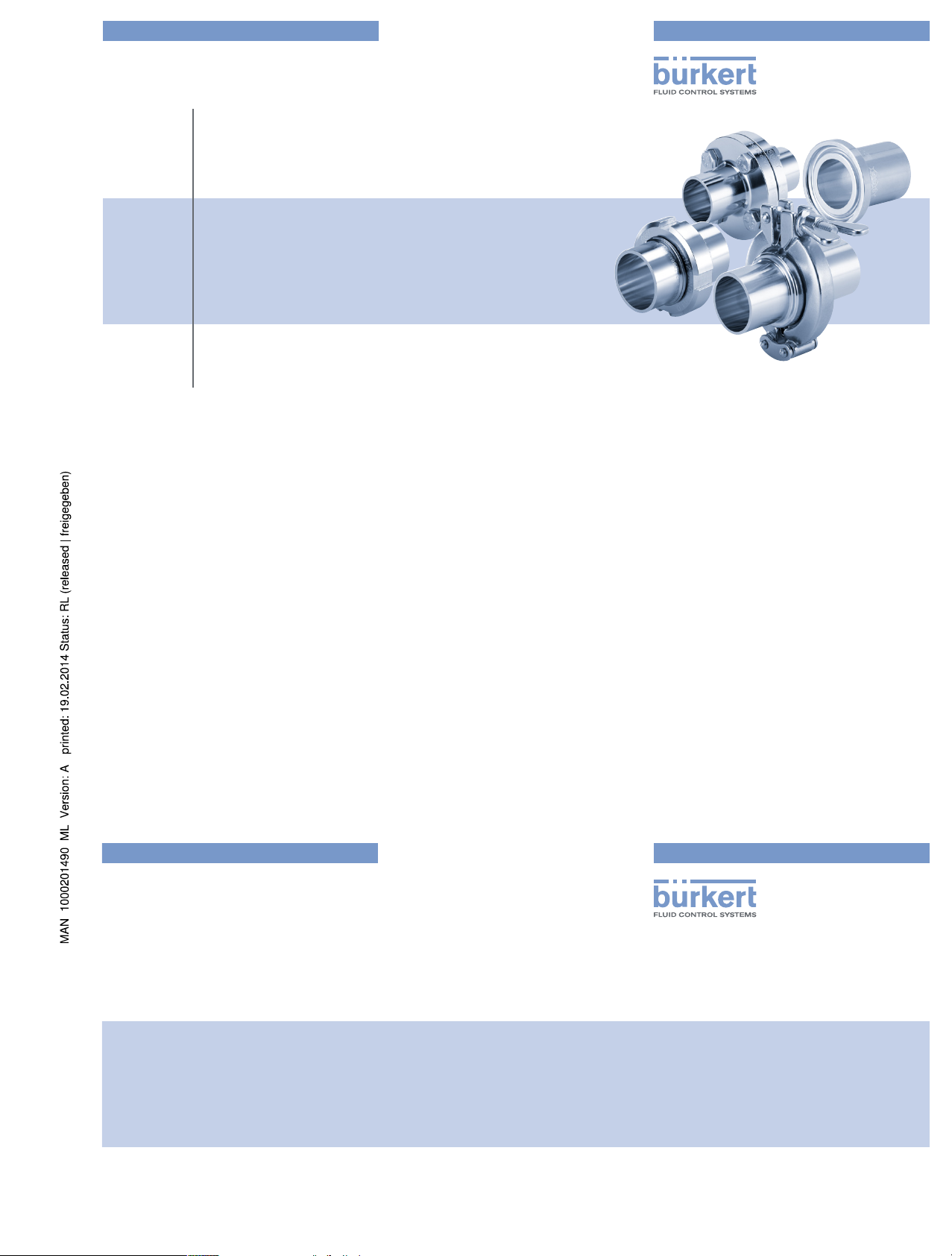
Type BBS-03, BBS-05, BBS-06, BBS-25
Sterile connection elements
Sterile Verbindungselemente
Raccords union stériles
Bedienungsanleitung
Manuel d‘utilisation
Operating Instructions
www.burkert.com
International address
www.burkert.com → Bürkert → Company → Locations
Manuals and data sheets on the Internet: www.burkert.com
Bedienungsanleitungen und Datenblätter im Internet: www.buerkert.de
Instructions de service et fiches techniques sur Internet : www.buerkert.fr
© 2013 Bürkert Werke GmbH
Operating Instr uctions 1402/01_EU-ML _00810203 / Original DE
Bürkert Fluid Control Systems
Sales Center
Christian-Bürkert-Str. 13-17
D-74653 Ingelfingen
Tel. + 49 (0) 7940 - 10 91 111
Fax + 49 (0) 7940 - 10 91 448
E-mail: info@de.buerkert.com
Page 2
2
1. THE OPERATING INSTRUCTIONS
The operating instructions contain important information.
• Read the instructions carefully and follow the safety instructions in
particular.
• Keep the instructions in a location where they are available to every
user.
• The liability and warranty for types BBS-03, BBS-05, BBS-06 and
BBS-25 do not apply if the procedures in the instructions are not
observed.
1.1. Symbols
→ designates a procedure which you must carry out.
Warning of injuries:
DANGER!
Immediate danger! Serious or fatal injuries.
WARNING!
Possible danger! Serious or fatal injuries.
CAUTION!
Danger! Moderate or minor injuries.
Warning of damage:
NOTE!
2. INTENDED USE
Non-authorized use of Type BBS-03, BBS-05, BBS-06 and
BBS-25 may be dangerous to people, nearby equipment and
the environment.
• Type BBS-03, BBS-05, BBS-06 or BBS-25 has been designed
as a connection between pipelines for the flow of gases and
liquids in the sterile area.
• Use according to the authorized data, operating conditions, and
conditions of use specified in the contract documents and operating instructions.
• Correct transportation, storage and installation, as well as careful
use and maintenance are essential for reliable and faultless
operation.
• Use the connection elements only as intended.
2.1. Restrictions
If exporting the products, observe any existing restrictions.
2.2. Definitions of terms
The term "connection element" used in these instructions always stands
for Type BBS-03, BBS-05, BBS-06 and BBS-25.
english
3
4. GENERAL INFORMATION
4.1. Contact address
Germany
Bürkert Fluid Control Systems
Sales Center
Christian-Bürkert-Str. 13-17
D-74653 Ingelfingen
Germany
Tel. + 49 (0) 7940 - 10 91 111
Fax + 49 (0) 7940 - 10 91 448
Email: info@de.buerkert.com
International
Contact addresses can be found on the final pages of the printed
operating instructions. And also on the Internet at: www.burkert.com
4.2. Warranty
The warranty is only valid if the connection elements are used as
intended in accordance with the specified application conditions.
4.3. Information on the Internet
The operating instructions and data sheets for Types BBS-03, BBS-05,
BBS-06 and BBS-25 can be found on the Internet at: www.burkert.com
3. BASIC SAFETY INSTRUCTIONS
These safety instructions do not take into account any contingencies and
events which may arise during the installation, operation and maintenance
of the connection elements.
Danger – high pressure and discharge of medium!
• Before loosening the lock nut or locking clamp, always turn off the
pressure and vent the lines.
• Wear protective equipment if media is hazardous.
General hazardous situations
• Do not make any internal or external changes to the connection
element.
• Ensure that the system cannot be activated unintentionally.
• Installation and maintenance work may be carried out only by
authorized technicians with the appropriate tools.
• The connection elements may be operated only when in perfect
condition and in consideration of the operating instructions.
• As far as inspection, maintenance and repairs are concerned,
observe national provisions of the country in which the connection
elements are installed.
• The general rules of technology apply to application planning and
operation of the connection elements.
english
4
5. TECHNICAL DATA
5.1. Conformity
The connection elements of Type BBS-03, BBS-05, BBS-06 and
BBS-25 comply with EC Directives in accordance with the
EC Declaration of Conformity.
5.2. Standards (if applicable)
The applied standards which are used to demonstrate compliance with
the EC Directives are listed in the EC type test certificate and/or the
EC Declaration of Conformity.
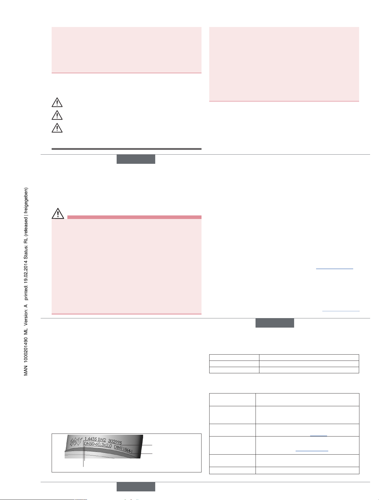
5.3. Identification
Information on material and pipe dimensions can be found on the
stamping on the connection element. The identification number of the
connection element can be found on the supplied 3.1 certificate.
Material
Pipe dimension
Batch number
Standard
Fig. 1: Example of identification of the connection element
5.4. Sealing materials
Seal material Operating temperature
EPDM –40 °C to 90 °C, briefly up 140 °C
FEP -60 °C to 160 °C, briefly up 205 °C
Tab. 1: Material of O-rings (BBS-03, -05, -06) or clamp seal (BBS-25).
5.5. General technical data
Material comes into
contact with medium
Stainless steel 1.4435 BN2 (316L)
Material does not
comes into contact
with medium
Stainless steel 1.4305 or equivalent
Pipe dimensions
See label on connection element
(Example: "Fig. 1")
Permitted
application
temperature
Depending on sealing material,
see "Tab. 1" page 4
Ambient
temperature
–20 °C to +80 °C
Media Gases or liquids
english
Type BBS-03, -05, -06, -25
Page 3
5
5.5.1. Operating pressure
BBS-03, BBS-05 and BBS-06 as sterile orbital connection:
–1 to +16 bar (depending on the temperature).
BBS-03 and BBS-05
according to DIN 11864
BBS-06 according to DIN
11864
ISO DN08 to DN25 = 40 bar
ISO DN32 to DN80 = 25 bar
DIN DN10 to DN40 = 40 bar
DIN DN50 to DN100 = 25 bar
BS-OD DN½" to DN1½" = 40 bar
BS-OD DN2" to DN4" = 25 bar
ISO DN08 to DN25 = 25 bar
ISO DN32 to DN80 = 16 bar
ISO DN100 = 10 bar
DIN DN10 to DN40 = 25 bar
DIN DN50 to DN100 = 16 bar
DIN DN125 to DN150 = 10 bar
BS-OD DN½" to DN1½" = 25 bar
BS-OD DN2" to DN4" = 16 bar
BBS-25 according to DIN 11864
ISO DN08 to DN32 = 25bar
ISO DN40 to DN65 = 16bar
ISO DN80 to DN150 = 10bar
DIN DN04 to DN40 = 25bar
DIN DN50 to DN65 = 16bar
DIN DN80 to DN150 = 10bar
BS-OD DN¼" to DN1½" = 25bar
BS-OD DN2" to DN3" = 16bar
BS-OD DN4" to DN8" = 10bar
SMS DN06 to DN40 = 25bar
SMS DN50 to DN65 = 16bar
SMS DN80 to DN100 = 10bar
6. ASSEMBLY
WARNING!
Risk of injury from improper assembly!
• Installation must only be carried out by authorized technicians and
with the appropriate tools!
• Secure system from unintentional activation.
6.1. Welding in the pipe connection
NOTE!
Damage to the welding ends!
• Remove end protection just before welding.
Leak due to damaged sealing contour!
• To ensure the sealing function, protect the sealing contour during
installation, welding and cleaning procedures.
Leak due to damaged seal!
• It is essential to remove the seal before welding and protect it
from dust, flying sparks and other influences!
Before welding:
→ Connect the parts positively in a protective gas shield.
english
6
→ For type BBS-03: Unscrew pipe connection!
Pull union nut on the liner side over the area to be welded onto
the pipe part to be welded on.
Welding
We recommend welding the connections using orbital welding
machines.
→ Always supply the weld with an inert gas.
→ Always form root seam welds.
→ Carefully clean welded joint.
→ Manual welding is possible. In doing so, use a higher-alloy filler
metal than the base material of the connection.
After welding:
When cleaning the weld seam by grinding or acid cleaning, observe
the following before assembling the connection:
• Carefully remove all grinding dust and acid-cleaning residue.
• Do not damage the label.
• There must be no material abrasion on the sealing edges. Material
abrasion will result in sharp-edged sealing contours and a damaged
seal.
• Check sealing contour for damage.
We recommend preparing a welding report.
6.2. Installing the seal
NOTE!
Damage to the EPDM and FEP seal!
• Sealing contours and contact areas must be free of contaminants.
• Do not use any pointed metallic objects.
• Never install FEP seals by force – e.g. by kinking. Even the slightest damage will result in leaks!
Damaged seals must be replaced!
→ Remove protective caps from sealing contours (protective caps
only for small delivery quantities or per order)
Type BBS-03, BBS-05 and BBS-06:
→ Insert O-ring before assembling the connection element into the
threaded connection or liner.
EPDM seals: Do not install using grease or oil!
If required, glycerin can be used as an installation aid.
FEP seals: Install by lubricating the surface with silicone grease
(FDA-compliant).
O-ring must be located firmly and tightly in the designated groove and
must not protrude into the pipe connection.
english
7
Type BBS-25:
→ Insert clamp seal into the threaded connection before screwing the
connection element together.
EPDM seals: Do not install using grease or oil!
If required, glycerin can be used as an installation aid.
Clamp seal must be located centrically and firmly and tightly in the
designated groove and must not protrude into the pipe connection.
6.3. Installing the pipe connection
→ Ensure that the seal is located correctly in the sealing contour.
→ Assemble both connection parts so that they are in alignment
(concentric deviation and angular offset of the pipe ends
max. +/–0.5 % of the outer pipe diameter)
Type BBS-03
→ Pull union nut over the liner.
→ We recommend lubricating the thread with suitable grease.
→ Manually turn union nut clockwise on the threaded connection.
Ensure that the connection turns freely, do not use force.
→ Tighten union nut using a suitable tool.
We recommend using flanges from DN 40.
Type BBS-06
→ Insert hexagon bolts through the screw holes in the flange.
→ Push circlip over the ends of the bolts.
→ Turn nuts on to the bolt threads, tighten by hand.
→ Tighten bolts crosswise using a suitable tool until flange sheets are
firmly situated one on top of the other.
Type BBS-05 and BBS-25
NOTE!
Damage to the connection element!
• Do not use any tools to install the clamp.
→ Manually place clamp over the connection.
→ Insert clamp screw into the designated slot, but do not use force.
→ Check that the clamp is seated correctly.
→ Carefully and evenly tighten the wing nut by hand until both pipe
components are firmly situated one on top of the other.
english
Type BBS-03, -05, -06, -25
Page 4
8
7. START-UP
WARNING!
Risk of injury from improper operation!
Improper operation may result in injuries as well as damage to the
connection element and the surrounding area.
• Before start-up, ensure that the operating personnel are familiar
with and completely understand the contents of the operating
instructions.
• Observe the safety instructions and intended use.
• Only adequately trained personnel may start up the equipment/the
connection element.
• Following assembly, ensure a controlled restart.
• When starting up the equipment, ensure that no unauthorized voltage increases and pressure surges can occur.
NOTE!
Dama
ge to the seals when cleaning the pipelin
e systems.
• Clean the pipeline systems preferably with a cleaning agent which
does not damage the seals.
• Do not clean the connection elements with wire brushes or
machines which cause abrasion of the surface.
• When using mechanical pipeline monitoring devices, ensure
that they do not damage the sealing elements (also the sealing
contour).
Damaged seals must be replaced!
english
9
8. MAINTENANCE
WARNING!
Danger – high pressure and discharge of medium!
• Before loosening the lock nut or locking clamp, always turn off the
pressure and vent the lines.
• Wear protective equipment if media is hazardous.
• Lock nuts or locking clamps of the connection elements on pressurized lines may be retightened only by technicians in consideration of special precautions.
• When shutting down the equipment, ensure that no unauthorized
voltage increases and pressure surges can occur.
• Following maintenance, ensure a controlled restart.
Have the connection elements serviced regularly by technicians!
We recommend a maintenance interval of 6 months.
Inspection and maintenance work includes in particular monitoring and
ensuring the
• leak-tightness,
• identification,
• proper mode of operation of the safety and warning devices.
Opening the screw connection Types BBS-03 and BBS-06
→ Follow safety instructions!
→ Slacken lock nut or lock screws until they can still hold the pipe
ends.
→ Vent the pipe ends slightly and slacken them until they no longer
stick to each other.
→ Remove lock nut or lock screws.
→ Loosen pipe connection.
Opening the clamp connection Types BBS-05 and BBS-25
→ Follow safety instructions!
→ Open wing nut until the locking clamp still holds the pipe
ends.
→ Vent the pipe ends slightly and slacken them until they no longer
stick to each other.
→ Remove locking clamp.
→ Loosen pipe connection.
english
10
9. TRANSPORTATION, STORAGE,
DISPOSAL
NOTE!
Transport damage!
Inadequately protected connection elements may be damaged during
transportation.
• Transport the connection element in a firmly assembled state, protected against moisture and dirt, in shock-resistant packaging.
• The welding ends must be protected by end caps.
Incorrect storage may damage the connection element.
• Prevent the temperature from exceeding or dropping below the
permitted storage temperature.
• Store the connection element in a dry and dust-free location!
• Store EPDM O-rings and FEP O-rings dry and protected from
UV radiation and for not longer than 3 years.
• Storage temperature -40 to +80°C.
Damage to the environment caused by device components contaminated with media.
• Dispose of the device and packaging in an environmentally friendly
manner!
• Observe applicable disposal and environmental regulations.
english
Type BBS-03, -05, -06, -25
Page 5

Type BBS-03, BBS-05, BBS-06, BBS-25
Sterile connection elements
Sterile Verbindungselemente
Raccords union stériles
Bedienungsanleitung
Manuel d‘utilisation
Operating Instructions
www.burkert.com
International address
www.burkert.com → Bürkert → Company → Locations
Manuals and data sheets on the Internet: www.burkert.com
Bedienungsanleitungen und Datenblätter im Internet: www.buerkert.de
Instructions de service et fiches techniques sur Internet : www.buerkert.fr
© 2013 Bürkert Werke GmbH
Operating Instr uctions 1402/01_EU-ML _00810203 / Original DE
Bürkert Fluid Control Systems
Sales Center
Christian-Bürkert-Str. 13-17
D-74653 Ingelfingen
Tel. + 49 (0) 7940 - 10 91 111
Fax + 49 (0) 7940 - 10 91 448
E-mail: info@de.buerkert.com
Page 6

12
1. DIE BEDIENUNGSANLEITUNG
Die Bedienungsanleitung enthält wichtige Informationen.
• Anleitung sorgfältig lesen und besonders die Hinweise zur Sicherheit
beachten.
• Anleitung so aufbewahren, dass sie jedem Benutzer zur Verfügung
steht.
• Haftung und Gewährleistung für Typ BBS-03, BBS-05, BBS-06 und
BBS-25 entfällt, wenn die Anweisungen der Anleitung nicht beachtet
werden.
1.1. Darstellungsmittel
→ markiert einen Arbeitsschritt, den Sie ausführen müssen.
Warnung vor Verletzungen:
GEFAHR!
Unmittelbare Gefahr! Schwere oder tödliche Verletzungen.
WARNUNG!
Mögliche Gefahr! Schwere oder tödliche Verletzungen.
VORSICHT!
Gefahr! Mittelschwere oder leichte Verletzungen.
Warnung vor Sachschäden:
HINWEIS!
2. BESTIMMUNGSGEMÄSSER
GEBRAUCH
Bei nicht bestimmungsgemäßem Gebrauch des Typs BBS-03,
BBS-05, BBS-06 und BBS-25 können Gefahren für Personen,
Anlagen in der Umgebung und die Umwelt entstehen.
• Typ BBS-03, BBS-05, BBS-06 bzw. BBS-25 ist als Verbindung
von Rohrleitungen zum Durchfluss von Gasen und Flüssigkeiten im
sterilen Bereich konzipiert.
• Für den Einsatz die in den Vertragsdokumenten und der Bedienungsanleitung spezifizierten zulässigen Daten, Betriebs- und Einsatzbedingungen beachten.
• Voraussetzungen für den sicheren und einwandfreien Betrieb sind
sachgemäßer Transport, sachgemäße Lagerung und Installation
sowie sorgfältige Bedienung und Instandhaltung.
• Setzen Sie die Verbindungselemente nur bestimmungsgemäß ein.
2.1. Beschränkungen
Bei der Ausfuhr der Produkte gegebenenfalls bestehende Beschränkungen beachten.
2.2. Begriffsdefinition
Der in dieser Anleitung verwendete Begriff „Verbindungselement“ steht
immer für den Typ BBS-03, BBS-05, BBS-06 und BBS-25.
deutsch
13
4. ALLGEMEINE HINWEISE
4.1. Kontaktadresse
Deutschland
Bürkert Fluid Control Systems
Sales Center
Christian-Bürkert-Str. 13-17
D-74653 Ingelfingen
Tel. + 49 (0) 7940 - 10 91 111
Fax + 49 (0) 7940 - 10 91 448
E-mail: info@de.buerkert.com
International
Die Kontaktadressen finden Sie auf den letzten Seiten der gedruckten
Bedienungsanleitung. Außerdem im Internet unter: www.burkert.com
4.2. Gewährleistung
Voraussetzung für die Gewährleistung ist der bestimmungsgemäße
Gebrauch der Verbindungselemente unter Beachtung der spezifizierten
Einsatzbedingungen.
4.3. Informationen im Internet
Bedienungsanleitungen und Datenblätter zum Typ BBS-03, BBS-05,
BBS-06 und BBS-25 finden Sie im Internet unter: www.buerkert.de
3. GRUNDLEGENDE
SICHERHEITSHINWEISE
Diese Sicherheitshinweise berücksichtigen keine Zufälligkeiten und Ereignisse, die bei Montage, Betrieb und Wartung der Verbindungselemente
auftreten können.
Gefahr durch hohen Druck und Mediumsaustritt!
• Vor dem Lösen von Verschlussmutter bzw. Verschlussklammer unbedingt den Druck abschalten und Leitungen entlasten.
• Bei gefährlichen Medien Schutzausrüstung tragen.
Allgemeine Gefahrensituationen
• Am Verbindungselement keine inneren oder äußeren Veränderungen
vornehmen.
• Beachten, dass die Anlage nicht unbeabsichtigt betätigt werden kann.
• Installations- und Instandhaltungsarbeiten dürfen nur von autorisiertem Fachpersonal mit geeignetem Werkzeug ausgeführt werden.
• Die Verbindungselemente nur in einwandfreiem Zustand und unter
Beachtung der Bedienungsanleitung betreiben.
• Bei Inspektion, Wartung und Instandsetzung nationale Bestimmungen
des Aufstellungslands beachten.
• Für die Einsatzplanung und den Betrieb der Verbindungselemente
die allgemeinen Regeln der Technik einhalten.
deutsch
14
5. TECHNISCHE DATEN
5.1. Konformität
Die Verbindungselemente Typ BBS-03, BBS-05, BBS-06 und
BBS-25 sind konform zu den EG-Richtlinien entsprechend der
EG-Konformitätserklärung.
5.2. Normen (soweit anwendbar)
Die angewandten Normen, mit denen die Konformität mit den EG-Richtlinien nachgewiesen wird, sind in der EG-Baumusterprüfbescheinigung
und/oder der EG-Konformitätserklärung nachzulesen.
5.3. Kennzeichnung
Angaben zu Material und Rohrmaß sind der Prägung auf dem
Verbindungselement zu entnehmen. Die Identnummer des Verbindungselements entnehmen Sie bitte dem mitgelieferten 3.1-Zeugnis.
Material
Rohrmaß
Chargennummer
Norm
Bild 1: Beispiel für die Kennzeichnung des Verbindungselements
5.4. Dichtungsmaterialien
Dichtwerkstoff Betriebstemperatur
EPDM –40 °C bis 90 °C, kurzzeitig bis 140 °C
FEP –60 °C bis 160 °C, kurzzeitig bis 205 °C
Tab. 1: Material O-Ringe (BBS-03, -05, -06) bzw. Clamp-Dichtung (BBS-25).
5.5. Allgemeine technische Daten
Material
mediumberührt
Edelstahl 1.4435 BN2 (316L)
Material
nicht mediumberührt
Edelstahl 1.4305 oder gleichwertig
Rohrmaße
siehe Beschriftung Verbindungselement
(Beispiel: „Bild 1“)
zulässige
Einsatztemperatur
je nach Dichtungsmaterial,
siehe „Tab. 1“ auf Seite 14
Umgebungs-
temperatur
–20 °C bis +80 °C
Medien Gase oder Flüssigkeiten
deutsch
Typ BBS-03, -05, -06, -25
Page 7

15
5.5.1. Betriebsdruck
BBS-03, BBS-05 und BBS-06 als Steril-Orbital-Verbindung:
–1 bis +16 bar (in Abhängigkeit der Temperatur).
BBS-03 und BBS-05
nach DIN 11864
BBS-06 nach DIN 11864
ISO DN08 bis DN25 = 40 bar
ISO DN32 bis DN80 = 25 bar
DIN DN10 bis DN40 = 40 bar
DIN DN50 bis DN100 = 25 bar
BS-OD DN½” bis DN1½” = 40 bar
BS-OD DN2” bis DN4” = 25 bar
ISO DN08 bis DN25 = 25 bar
ISO DN32 bis DN80 = 16 bar
ISO DN100 = 10 bar
DIN DN10 bis DN40 = 25 bar
DIN DN50 bis DN100 = 16 bar
DIN DN125 bis DN150 = 10 bar
BS-OD DN½” bis DN1½” = 25 bar
BS-OD DN2” bis DN4” = 16 bar
BBS-25 nach DIN 11864
ISO DN08 bis DN32 = 25bar
ISO DN40 bis DN65 = 16bar
ISO DN80 bis DN150 = 10bar
DIN DN04 bis DN40 = 25bar
DIN DN50 bis DN65 = 16bar
DIN DN80 bis DN150 = 10bar
BS-OD DN¼“ bis DN1½“ = 25bar
BS-OD DN2“ bis DN3“ = 16bar
BS-OD DN4“ bis DN8“ = 10bar
SMS DN06 bis DN40 = 25bar
SMS DN50 bis DN65 = 16bar
SMS DN80 bis DN100 = 10bar
6. MONTAGE
WARNUNG!
Verletzungsgefahr bei unsachgemäßer Montage!
• Die Montage darf nur autorisiertes Fachpersonal mit geeignetem
Werkzeug durchführen!
• Anlage vor unbeabsichtigtem Betätigen sichern.
6.1. Einschweißen der Rohrverbindung
HINWEIS!
Beschädigung der Schweiß-Enden!
• Endenschutz erst unmittelbar vor dem Verschweißen entfernen.
Undichtheit durch beschädigte Dichtkontur!
• Zur Sicherstellung der Dichtfunktion die Dichtkontur während
Montage, Schweißen und Reinigungsverfahren schützen.
Undichtheit durch beschädigte Dichtung!
• Dichtung vor dem Schweißen unbedingt entfernen und vor Staub,
Funkenflug und anderen Einflüssen schützen!
Vor dem Schweißen:
→ Verbindung formschlüssig unter Schutzgas heften.
deutsch
16
→ Bei Typ BBS-03: Rohrverbindung auseinanderschrauben!
Überwurfmutter auf der Bundstutzenseite über die zu verschweißenden Stelle auf das anzuschweißende Rohrteil ziehen.
Schweißen
Wir empfehlen, die Verbindungen mit Orbitalschweißmaschinen zu
schweißen.
→ Zur Schweißung immer ein Edelgas zuführen.
→ Wurzelnahtschweißungen immer formieren.
→ Schweißstelle sorgfältig reinigen.
→ Manuelle Schweißung ist möglich. Dabei höher legierten Schweiß-
zusatz verwenden als das Grundmaterial der Verbindung aufweist.
Nach dem Schweißen:
Bei Schweißnahtreinigung mittels Schleifen oder Beizen vor dem
Zusammenbau der Verbindung beachten:
• Alle Schleifstaub- und Beizereste sorgfältig entfernen.
• Beschriftung nicht beschädigen.
• An den Dichtkanten darf kein Materialabtrag vorgenommen werden.
Materialabtrag führt zu scharfkantigen Dichtkonturen und damit zur
Verletzung der Dichtung.
• Dichtkontur auf Beschädigung kontrollieren.
Wir empfehlen die Erstellung eines Schweißprotokolls.
6.2. Einbau der Dichtung
HINWEIS!
Beschädigung der EPDM- und FEP-Dichtung!
• Dichtkonturen und Kontaktflächen müssen frei von Verunreinigungen
sein.
• Keine spitzen metallischen Gegenstände benützen.
• FEP-Dichtungen keinesfalls gewaltsam – z. B. durch Knicken –
montieren. Selbst kleinste Verletzungen führen zu Undichtheit!
Verletzte Dichtungen müssen ersetzt werden!
→ Schutzkappen auf Dichtkonturen entfernen (Schutzkappen nur bei
kleinen Liefermengen oder auf Bestellung)
Typ BBS-03, BBS-05 und BBS-06:
→ O-Ring vor dem Zusammenfügen des Verbindungselements in den
Gewinde- bzw. Bundstutzen einlegen.
EPDM-Dichtungen: zur Montage kein Fett oder Öl benützen!
Wenn nötig, kann Glyzerin als Hilfsmittel verwendet werden.
FEP-Dichtungen: zur Montage Oberfläche mit Silikonfett (FDA-
konform) fetten.
O-Ring muss in der dafür vorgesehenen Nut fest und eng anliegen und
darf nicht in die Rohrverbindung ragen.
deutsch
17
Typ BBS-25:
→ Clamp-Dichtung vor dem Zusammenschrauben des Verbindungs-
elements in den Gewindestutzen einlegen.
EPDM-Dichtungen: zur Montage kein Fett oder Öl benützen!
Wenn nötig, kann Glyzerin als Hilfsmittel verwendet werden.
Clamp-Dichtung muss zentrisch und in der dafür vorgesehenen Nut fest
und eng anliegen und darf nicht in die Rohrverbindung ragen.
6.3. Montage der Rohrverbindung
→ Sicherstellen, dass die Dichtung richtig in der Dichtkontur liegt.
→ beide Verbindungsteile zusammenfügen, so dass sie fluchtend auf-
einandertreffen (konzentrische Abweichung und Winkelversatz der
Rohr-Enden max. +/–0,5 % des Rohr-Aussendurchmessers)
Typ BBS-03
→ Überwurfmutter über den Bundstutzen ziehen.
→ Wir empfehlen, das Gewinde mit einem geeignetem Fett einzufetten.
→ Überwurfmutter von Hand im Uhrzeigersinn auf Gewindestutzen
drehen. Auf leichtgängige Verschraubung achten, keine Gewalt
anwenden.
→ Überwurfmutter mit geeignetem Werkzeug anziehen.
Wir empfehlen ab DN 40 Flansche einzusetzen.
Typ BBS-06
→ Sechskantschrauben durch die Schraubenlöcher des Flansches
stecken.
→ Federring über die Schrauben-Enden schieben.
→ Muttern auf die Schraubengewinde drehen, von Hand festziehen.
→ Schrauben mit geeignetem Werkzeug über Kreuz anziehen, bis
Flanschblätter fest aufeinander liegen.
Typ BBS-05 und BBS-25
HINWEIS!
Beschädigung des Verbindungselements!
• Zur Klammermontage keine Werkzeuge verwenden.
→ Klammer von Hand über die Verbindung legen.
→ Klammerschraube in dafür vorgesehenen Schlitz einfädeln, dabei
keine Gewalt anwenden.
→ Richtigen Sitz der Klammer kontrollieren.
→ Flügelmutter von Hand vorsichtig und gleichmäßig anziehen, so dass
beide Rohrbauteile fest aufeinander liegen.
deutsch
Typ BBS-03, -05, -06, -25
Page 8

18
7. INBETRIEBNAHME
WARNUNG!
Verletzungsgefahr bei unsachgemäßem Betrieb!
Nicht sachgemäßer Betrieb kann zu Verletzungen sowie Schäden am
Verbindungselement und seiner Umgebung führen.
• Vor der Inbetriebnahme muss gewährleistet sein, dass der Inhalt
der Bedienungsanleitung dem Bedienungspersonal bekannt ist und
vollständig verstanden wurde.
• Die Sicherheitshinweise und der bestimmungsgemäße Gebrauch
müssen beachtet werden.
• Nur ausreichend geschultes Personal darf die Anlage/das Verbindungselement in Betrieb nehmen.
• Nach der Montage einen kontrollierten Wiederanlauf gewährleisten.
• Anlage so in Betrieb nehmen, dass sich keine unzulässigen Spannungserhöhungen und Druckschläge ergeben können.
HINWEIS!
Beschä
digung der Dichtungen beim Reinigen der
Rohrleitun
gssysteme.
• Zur Reinigung der Rohrleitungssysteme möglichst Reinigungsmittel
verwenden, welche die Dichtungen nicht beschädigen.
• Zur Reinigung der Verbindungselemente keine Drahtbürsten oder
Maschinen benützen, die einen Oberflächenabtrag zur Folge haben.
• Bei Verwendung mechanischer Rohrleitungs-Kontrollgeräte beachten, dass diese keine Beschädigung der Dichtelemente (auch der
Dichtkontur) verursachen.
Beschädigte Dichtungen müssen ausgetauscht werden!
deutsch
19
8. WARTUNG
WARNUNG!
Gefahr durch hohen Druck und Mediumsaustritt!
• Vor dem Lösen von Verschlussmutter bzw. Verschlussklammer
unbedingt den Druck abschalten und Leitungen entlasten.
• Bei gefährlichen Medien Schutzausrüstung tragen.
• An unter Druck stehenden Leitungen dürfen Verschlussmuttern bzw.
Verschlussklammer der Verbindungselemente nur von Fachpersonal
unter Beachtung besonderer Vorsichtsmaßnahmen nachgezogen
werden.
• Anlage so abfahren, dass sich keine unzulässigen Spannungserhöhungen und Druckschläge ergeben können.
• Nach der Wartung einen kontrollierten Wiederanlauf gewährleisten.
Verbindungselemente regelmäßig durch fachkundiges Personal
warten! Wir empfehlen einen Wartungsintervall von 6 Monaten.
Zu den Inspektions- und Wartungsarbeiten gehören insbesondere die
Überwachung und Sicherstellung der
• Dichtheit,
• Kennzeichnung,
• ordnungsgemäßen Funktionsweise der Sicherheits- und
Warneinrichtungen.
Öffnen der Verschraubung Typ BBS-03 und BBS-06
→ Sicherheitshinweise beachten!
→ Verschlussmutter bzw. Verschlussschrauben so weit lockern, dass
sie die Rohrenden noch halten können.
→ Rohrenden leicht anlüften und lockern, dass sie nicht mehr anein-
ander haften.
→ Verschlussmutter bzw. Verschlussschrauben entfernen.
→ Rohrverbindung lösen.
Öffnen der Clamp-Verbindung Typ BBS-05 und BBS-25
→ Sicherheitshinweise beachten!
→ Flügelmutter so weit öffnen, dass die Verschlussklammer die Rohr-
enden noch hält.
→ Rohrenden leicht anlüften und lockern, dass sie nicht mehr anein-
ander haften.
→ Verschlussklammer entfernen.
→ Rohrverbindung lösen.
deutsch
20
9. TRANSPORT, LAGERUNG,
ENTSORGUNG
HINWEIS!
Transportschäden!
Unzureichend geschützte Verbindungselemente können durch den
Transport beschädigt werden.
• Verbindungselement in fest zusammengesetztem Zustand vor
Nässe und Schmutz geschützt in einer stoßfesten Verpackung
transportieren.
• Die Schweißenden müssen durch Endkappen geschützt sein.
Falsche Lagerung kann Schäden am Verbindungselement
verursachen.
• Eine Über- bzw. Unterschreitung der zulässigen Lagertemperatur
vermeiden.
• Verbindungselement trocken und staubfrei lagern!
• EPDM-O-Ringe und FEP-O-Ringe trocken und vor UV-Strahlung
geschützt und nicht länger als 3 Jahre lagern.
• Lagertemperatur –40 … +80 °C.
Umweltschäden durch von Medien kontaminierte Geräteteile.
• Gerät und Verpackung umweltgerecht entsorgen!
• Geltende Entsorgungsvorschriften und Umweltbestimmungen
einhalten.
deutsch
Typ BBS-03, -05, -06, -25
Page 9

Type BBS-03, BBS-05, BBS-06, BBS-25
Sterile connection elements
Sterile Verbindungselemente
Raccords union stériles
Bedienungsanleitung
Manuel d‘utilisation
Operating Instructions
www.burkert.com
International address
www.burkert.com → Bürkert → Company → Locations
Manuals and data sheets on the Internet: www.burkert.com
Bedienungsanleitungen und Datenblätter im Internet: www.buerkert.de
Instructions de service et fiches techniques sur Internet : www.buerkert.fr
© 2013 Bürkert Werke GmbH
Operating Instr uctions 1402/01_EU-ML _00810203 / Original DE
Bürkert Fluid Control Systems
Sales Center
Christian-Bürkert-Str. 13-17
D-74653 Ingelfingen
Tel. + 49 (0) 7940 - 10 91 111
Fax + 49 (0) 7940 - 10 91 448
E-mail: info@de.buerkert.com
Page 10

22
1. MANUEL
Le manuel contient des informations importantes.
• Lire attentivement le manuel et tenir particulièrement compte des
consignes de sécurité.
• Conserver le manuel afin qu'il soit accessible à tous les utilisateurs.
• La responsabilité et la garantie légale concernant les types
BBS-03, BBS-05, BBS-06 et BBS-25 sont exclues en cas de
non-respect des instructions contenues dans le manuel.
1.1. Symboles
→ Identifie une opération que vous devez effectuer.
Mise en garde contre les blessures :
DANGER !
Danger imminent ! Blessures graves ou mortelles.
AVERTISSEMENT !
Danger potentiel ! Blessures graves ou mortelles.
ATTENTION !
Danger ! Blessures légères ou de moyenne gravité.
Mise en garde contre les dommages matériels :
REMARQUE !
2. UTILISATION CONFORME
L'utilisation non conforme des types BBS-03, BBS-05, BBS-06
et BBS-25 peut présenter des dangers pour les personnes, les
installations avoisinantes et l'environnement.
• Le type BBS-03, BBS-05, BBS-06 ou BBS-25 est conçu pour
raccorder des tuyauteries assurant le débit de gaz et de liquides
en milieu stérile.
• Lors de l'utilisation, il convient de respecter les données et conditions d'utilisation et d'exploitation admissibles spécifiées dans le
manuel et dans les documents contractuels.
• Les conditions pour l'utilisation sûre et parfaite sont un transport,
un stockage et une installation dans les règles ainsi qu'une utilisation et une maintenance parfaites.
• N'utilisez jamais les raccords union pour un usage autre que celui
prévu.
2.1. Limitations
Lors de l'exportation des produits, veuillez respecter les limitations éventuelles existantes.
2.2. Définition des termes
Le terme « raccord union » utilisé dans ce manuel désigne toujours les
types BBS-03, BBS-05, BBS-06 et BBS-25.
français
23
4. INDICATIONS GÉNÉRALES
4.1. Adresse
Allemagne
Bürkert Fluid Control Systems
Sales Center
Christian-Bürkert-Str. 13-17
D-74653 Ingelfingen
Tél. + 49 (0) 7940 - 10 91 111
Fax + 49 (0) 7940 - 10 91 448
E-mail: info@de.buerkert.com
International
Les adresses se trouvent aux dernières pages du manuel imprimé.
Également sur internet sous : www.burkert.com
4.2. Garantie légale
La condition pour bénéficier de la garantie légale est l'utilisation conforme
des raccords union dans le respect des conditions d'utilisation spécifiées.
4.3. Informations sur Internet
Vous trouverez les manuels et les fiches techniques concernant les
types BBS-03, BBS-05, BBS-06 et BBS-25 sur Internet sous :
www.burkert.fr
3. CONSIGNES DE SÉCURITÉ
FONDAMENTALES
Ces consignes de sécurité ne tiennent pas compte des hasards et des
événements pouvant survenir lors du montage, de l'exploitation et de
l'entretien des raccords union.
Danger dû à la pression élevée et à la sortie de fluide !
• Avant de desserrer l'écrou-raccord et la bride de fermeture, il faut
absolument couper la pression et purger l'air des conduites.
• En cas d'utilisation de fluides toxiques, porter l'équipement de protection.
Situations dangereuses d'ordre général
• N'apportez pas de modifications internes ou externes au raccord union.
• L'actionnement par inadvertance de l'installation ne doit pas être possible.
• Les travaux d'installation et de maintenance doivent être effectués
uniquement par des techniciens qualifiés et habilités disposant de
l'outillage approprié.
• Les raccords union doivent être utilisés uniquement en parfait état et en
respectant le manuel.
• Respecter les dispositions nationales en vigueur dans le pays d'installation lors de l'inspection, de l'entretien et de la réparation.
• Les règles générales de la technique sont d'application pour planifier
l'utilisation des raccords union.
français
24
5. CARACTÉRISTIQUES TECHNIQUES
5.1. Conformité
Les raccords union de types BBS-03, BBS-05, BBS-06 et BBS-25
satisfont aux directives CE conformément à la déclaration de
conformité CE.
5.2. Normes (si applicables)
Les normes utilisées attestant de la conformité avec les directives CE
figurent dans l'attestation CE de type et/ou la déclaration de
conformité CE.
5.3. Identification
Les informations concernant le matériau et la dimension du tube sont
gravées sur le raccord union. Vous trouverez le numéro d'identification
du raccord union dans le certificat 3.1 fourni.
Matériau
Dimension du tube
Numéro de lot
Norme
Fig. 1: Exemple d'identification du raccord union
5.4. Matériaux d'étanchéité
Matériau du joint Température de service
EPDM -40 à 90 °C, brièvement jusqu'à 140 °C
FEP -60 à 160 °C, brièvement jusqu'à 205 °C
Tab. 1: Matériau des joints toriques (BBS-03, -05, -06) et du joint clamp
(BBS-25).
5.5. Caractéristiques techniques générales
Matériau en contact
avec le fluide
Acier inoxydable 1.4435 BN2 (316L)
Matériau pas en
contact avec le fluide
Acier inoxydable 1.4305 ou similaire
Dimensions du tube
Voir les informations sur le raccord union
(exemple : « Fig. 1 »)
Température
d'utilisation
admissible
selon le matériau d'étanchéité,
voir « Tab. 1 » page 24
Température
ambiante
-20 °C à +80 °C)
Fluides Gaz ou liquides
français
Type BBS-03, -05, -06, -25
Page 11

25
5.5.1. Pression de service
BBS-03, BBS-05 et BBS-06 comme raccord orbital stérile :
-1 à +16 bar (en fonction de la température).
BBS-03 et BBS-05
selon DIN 11864
BBS-06 selon DIN 11864
ISO DN08 à DN25 = 40 bar
ISO DN32 à DN80 = 25 bar
DIN DN10 à DN40 = 40 bar
DIN DN50 à DN100 = 25 bar
BS-OD DN½" à DN1½" = 40 bar
BS-OD DN2" à DN4" = 25 bar
ISO DN08 à DN25 = 25 bar
ISO DN32 à DN80 = 16 bar
ISO DN100 = 10 bar
DIN DN10 à DN40 = 25 bar
DIN DN50 à DN100 = 16 bar
DIN DN125 à DN150 = 10 bar
BS-OD DN½" à DN1½" = 25 bar
BS-OD DN2" à DN4" = 16 bar
BBS-25 selon DIN 11864
ISO DN08 à DN32 = 25 bar
ISO DN40 à DN65 = 16 bar
ISO DN80 à DN150 = 10 bar
DIN DN04 à DN40 = 25 bar
DIN DN50 à DN65 = 16 bar
DIN DN80 à DN150 = 10 bar
BS-OD DN¼" à DN1½" = 25 bar
BS-OD DN2" à DN3" = 16 bar
BS-OD DN4" à DN8" = 10 bar
SMS DN06 àDN40 = 25 bar
SMS DN50 à DN65 = 16 bar
SMS DN80 à DN100 = 10 bar
6. MONTAGE
AVERTISSEMENT !
Risque de blessures dû à un montage non conforme !
• Le montage doit être effectué uniquement par des techniciens qualifiés et habilités disposant de l'outillage approprié !
• Empêcher tout actionnement involontaire de l'installation.
6.1. Soudage du raccord de tuyauterie
REMARQUE !
Endommagement des extrémités à souder !
• Enlever la protection des extrémités juste avant de procéder au
soudage.
Fuites dues à un contour d'étanchéité endommagé !
• Pour garantir la fonction d'étanchéité, protéger le contour d'étanchéité pendant le montage, le soudage et le nettoyage.
Fuites dues à un joint endommagé !
• Toujours retirer le joint avant de procéder au soudage et le protéger de la poussière, des étincelles et d'autres influences !
Avant le soudage :
→ Pointer le raccord union sur toute sa surface sous gaz protecteur.
français
26
→ Avec le type BBS-03 dévisser le raccord de tuyauterie !
Positionner l'écrou raccord du côté de l'embout à collerette sur
l'endroit de la partie de tube à souder.
Soudage
Nous recommandons d'utiliser des soudeuses orbitales pour souder
les raccords.
→ Toujours utiliser un gaz rare pour souder.
→ Toujours former les soudures de passe de fond.
→ Nettoyer minutieusement la soudure.
→ Le soudage manuel est possible. Dans ce cas, utiliser un apport de
soudage plus fortement allié que le matériau de base du raccord.
Après le soudage :
Lors du nettoyage de la soudure par meulage ou décapage avant
assemblage du raccord :
• Retirer soigneusement tous les résidus de poussière de meulage et
de décapage.
• Ne pas endommager les informations.
• Aucun enlèvement de matière ne doit être effectué au niveau des
bords d'étanchéité. L'enlèvement de matière génère des contours
d'étanchéité à arêtes vives endommageant le joint.
• Contrôler la présence de dommages sur le contour d'étanchéité.
Nous recommandons d'établir un rapport de soudage.
6.2. Montage du joint
REMARQUE !
Endommagement du joint EPDM et du joint FEP !
• Les contours d'étanchéité et les surfaces de contact doivent être
parfaitement propres.
• Ne pas utiliser d'objets métalliques pointus.
• Ne jamais effectuer le montage des joints FEP en forçant, par ex.
en les pliant. Le moindre dommage peut être à l'origine de fuites !
Les joints endommagés doivent être remplacés !
→ Retirer les capuchons de protection des contours d'étanchéité
(capuchons de protection uniquement pour des livraisons de
petites quantités ou sur commande)
Types BBS-03, BBS-05 et BBS-06 :
→ Mettre le joint torique en place dans la tubulure filetée ou l'embout
à collerette avant d'assembler le raccord union.
Joints EPDM : ne pas utiliser de graisse ou d'huile pour
effectuer le montage !
Si nécessaire, utiliser de la glycérine.
Joints FEP : appliquer de la graisse silicone (conforme FDA) sur la
surface pour effectuer le montage.
français
27
Le joint torique doit être étroitement en contact dans la rainure prévue
à cet effet et ne doit pas dépasser dans le raccord de tuyauterie.
Type BBS-25 :
→ Mettre le joint clamp en place dans la tubulure filetée avant de
visser le raccord union.
Joints EPDM : ne pas utiliser de graisse ou d'huile pour
effectuer le montage !
Si nécessaire, utiliser de la glycérine.
Le joint clamp doit être étroitement en contact dans la rainure prévue à
cet effet et ne doit pas dépasser dans le raccord de tuyauterie.
6.3. Montage du raccord de tuyauterie
→ Assurez-vous que le joint est correctement en place dans le
contour d'étanchéité.
→ Assembler les deux parties du raccord de sorte qu'elles se
rejoignent parfaitement (écart concentrique et écart angulaire maxi
des extrémités de tube +/–0,5 % du diamètre extérieur du tube)
Type BBS-03
→ Positionner l'écrou-raccord sur l'embout à collerette.
→ Nous recommandons d'appliquer une graisse appropriée sur le
filetage.
→ Visser l'écrou-raccord à la main sur la tubulure filetée dans le sens
des aiguilles d'une montre. Veiller à la souplesse du vissage, ne
pas forcer.
→ Serrer l'écrou-raccord avec un outil approprié.
Nous recommandons d'utiliser des brides à partir du DN 40.
Type BBS-06
→ Faire passer les vis à tête hexagonale à travers les trous de vis de
la bride.
→ Glisser la rondelle Grower sur les extrémités de vis.
→ Visser les écrous sur les pas de vis, serrer à fond à la main.
→ Serrer les vis en croix avec un outil approprié jusqu'à ce que les
faces de bride soient parfaitement solidaires.
Types BBS-05 et BBS-25
REMARQUE !
Endommagement du raccord union !
• Ne pas utiliser d'outils pour le montage des brides.
→ Positionner la bride à la main sur le raccord.
français
Type BBS-03, -05, -06, -25
Page 12

28
→ Introduire la vis à tête rectangulaire dans la fente prévue à cet effet
sans forcer.
→ Vérifier le bon positionnement de la bride.
→ Serrer l'écrou à oreilles avec précaution et régulièrement à la
main de sorte que les deux parties de tube soient parfaitement
solidaires.
7. MISE EN SERVICE
AVERTISSEMENT !
Risque de blessures en cas d'utilisation non conforme !
Une utilisation non conforme peut entraîner des blessures et endommager le raccord union et son environnement.
• Avant la mise en service, il faut s'assurer que le contenu du manuel
est connu et parfaitement compris par les opérateurs.
• Respecter les consignes de sécurité et l'utilisation conforme.
• L'installation/le raccord union doit être mis(e) en service uniquement par un personnel suffisamment formé.
• Garantir un redémarrage contrôlé après le montage.
• Mettre l'installation en service en veillant à empêcher les augmentations de tension et les coups de bélier inadmissibles.
français
29
REMARQUE !
Endom
magement des joints lors du nettoyage des systèmes de
tuyauterie.
• Pour nettoyer les systèmes de tuyauterie, utiliser dans la mesure du
possible des produits de nettoyage n'endommageant pas les joints.
• Pour nettoyer les raccords union, ne pas utiliser de brosses métalliques ou de machines attaquant la surface.
• Si vous utilisez des appareils de contrôle mécaniques pour tuyauteries, veiller à ce que ceux-ci n'endommagent pas les éléments
d'étanchéité (ni le contour d'étanchéité).
Les joints endommagés doivent être remplacés !
8. ENTRETIEN
AVERTISSEMENT !
Danger dû à la pression élevée et à la sortie de fluide !
• Avant de desserrer l'écrou-raccord et la bride de fermeture, il faut
absolument couper la pression et purger l'air des conduites.
• En cas d'utilisation de fluides toxiques, porter l'équipement de
protection.
• Seuls les techniciens qualifiés sont autorisés à resserrer les
écrous-raccords et les brides de fermeture des raccords union sur
les conduites sous pression en respectant les mesures de sécurité
spécifiques.
• Mettre l'installation hors service en veillant à empêcher les augmentations de tension et les coups de bélier inadmissibles.
• Garantir un redémarrage contrôlé après l'entretien.
Faire effectuer régulièrement l'entretien des raccords union par
un personnel spécialisé. Nous recommandons de respecter une
périodicité d'entretien de 6 mois.
Font notamment partie des travaux d'inspection et d'entretien, la sur-
veillance et la garantie de
• l'étanchéité,
• l'identification
français
30
• et le parfait fonctionnement des dispositifs de sécurité et
d'avertissement.
Ouverture des raccords union, types BBS-03 et BBS-06
→ Respecter les consignes de sécurité !
→ Desserrer les écrous-raccords et les bouchons filetés juste ce qu'il
faut pour qu'ils puissent encore maintenir les extrémités de tube.
→ Soulever et desserrer légèrement les extrémités de tube de sorte
qu'elles soient désolidarisées.
→ Retirer les écrous-raccords et les bouchons filetés.
→ Desserrer le raccord de tuyauterie.
Ouverture du raccord clamp, types BBS-05 et BBS-25
→ Respecter les consignes de sécurité !
→ Desserrer l'écrou à oreilles juste ce qu'il faut pour que la bride de
fermeture puisse encore maintenir les extrémités de tube.
→ Soulever et desserrer légèrement les extrémités de tube de sorte
qu'elles soient désolidarisées.
→ Retirer la bride de fermeture.
→ Desserrer le raccord de tuyauterie.
9. TRANSPORT, STOCKAGE,
ÉLIMINATION
REMARQUE !
Dommages dus au transport !
Les raccords union insuffisamment protégés peuvent être endommagés pendant le transport.
• Transporter le raccord union, bien assemblé, à l'abri de l'humidité et
des impuretés et dans un emballage résistant aux chocs.
• Les extrémités à souder doivent être protégées par des capuchons.
Un mauvais stockage peut endommager le raccord union.
• Éviter le dépassement vers le haut ou le bas de la température de
stockage admissible.
• Stocker le raccord union au sec et à l'abri des poussières !
• Stocker les joints toriques EPDM et FEP au sec et à l'abri des UV,
la durée de stockage ne devant pas dépasser 3 ans.
• Température de stockage -40 à +80 °C.
Dommages à l'environnement causés par des pièces d'appareil
contaminées par des fluides.
• Éliminer l'appareil et l'emballage dans le respect de l'environnement !
• Respecter les prescriptions en matière d'élimination des déchets et
de protection de l'environnement en vigueur.
français
Type BBS-03, -05, -06, -25
 Loading...