

Page 1
Type 8032 / 8072
Flowmeter / Flow threshold detector
Durchfluss-Messgerät / -Schwellendetektor
Débitmètre / Détecteur à seuil du débit
Operating Instructions
Bedienungsanleitung
Manuel d‘utilisation
Page 2

We reserve the right to make technical changes without notice.
Technische Änderungen vorbehalten.
Sous réserve de modifications techniques.
© 2011-2013 Bürkert SAS
Operating Instructions 1304/1_EU-ML 00560375 / Original_FR
Page 3

Type 8032 / 8072
1. ABOUT THIS MANUAL .................................................................................3
1.1. Symbols used .......................................................................................3
1.2. Definition of the word "device" ....................................................3
2. INTENDED USE ................................................................................................4
3. BASIC SAFETY INFORMATION ...............................................................4
4. GENERAL INFORMATION ...........................................................................6
4.1. Manufacturer's address and international contacts .........6
4.2. Warranty conditions ...........................................................................6
4.3. Information on the Internet ............................................................6
5. DESCRIPTION ...................................................................................................6
5.1. Construction ..........................................................................................6
5.2. Measuring element ............................................................................6
5.3. Available versions of the SE32 electronic module ...........7
5.4. Description of the name plate .....................................................8
6. TECHNICAL DATA ...........................................................................................8
6.1. Conditions of use ................................................................................8
6.2. Compliance to standards and directives ................................8
6.3. General technical data .....................................................................9
6.3.1. Mechanical data ....................................................................9
6.3.2. General data .........................................................................10
6.3.3. Electrical data.......................................................................12
6.3.4. Data of the cables and wires ............................................13
7. INSTALLATION AND WIRING .................................................................14
7.1. Safety information ........................................................................... 14
7.2. Installation onto the pipe ............................................................. 15
7.2.1. Diagrams ...............................................................................15
7.2.2. Assembly of the 8032 / 8072 ..........................................16
7.3. Wiring ...................................................................................................... 17
7.3.1. Assembling the connectors ..............................................17
7.3.2. Wiring a version with transistor output and
EN175301-803 male fixed connector ...........................18
7.3.3. Wiring a version with 2 transistor outputs and a
5-pin M12 male fixed connector ......................................19
7.3.4. Wiring of the version with a single relay output ............. 21
7.3.5. Wiring of the version with a single current output ......... 22
7.3.6. Wiring the version with both relay and current
outputs (5-pin M12 fixed connector) ................................ 23
7.3.7. Wiring the version with relay and current out-
puts (8-pin M12 fixed connector) ...................................24
8. COMMISSIONING ........................................................................................ 27
8.1. Safety information ........................................................................... 27
English
1
Page 4
9. ADJUSTMENT AND FUNCTIONS .........................................................27
9.1. Safety information ........................................................................... 27
9.2. Operating levels ................................................................................28
9.3. Description of the display and the operating keys ........ 29
9.4. Process level ...................................................................................... 29
9.5. Configuration level - Parameters menu ...............................31
9.5.1. Selecting the unit of the flow rate ...................................32
9.5.2. Entering the K factor or having it determined by
teach-in ..................................................................................33
9.5.3. Configuring the relay or transistor output ......................34
9.5.4. Setting the flow rate range associated to the
4-20 mA output ...................................................................36
9.5.5. Choosing the filter of the flow rate ..................................36
9.5.6. entering the flow rate range related to the bar graph . 37
9.5.7. Adjusting the brightness of the backlight or
deactivating the backlight .................................................37
9.5.8. Activating and defining the access code to the
Configuration level ..............................................................38
9.5.9. Saving the modified parameters ......................................38
9.6. Configuration level - Test menu ...............................................39
9.6.1. Adjusting the 4-20 mA output .........................................40
9.7. Default settings ................................................................................. 41
9.8. Your settings for the 8032 / 8072 ...........................................41
10. MAINTENANCE AND TROUBLESHOOTING ................................42
10.1. Safety information ........................................................................... 42
10.2. Maintenance and cleaning ..........................................................42
10.3. If you encounter problems ..........................................................43
11. SPARE PARTS AND ACCESSORIES ............................................... 44
12. PACKAGING, TRANSPORT ...................................................................45
13. STORAGE ....................................................................................................... 45
14. DISPOSAL OF THE DEVICE ................................................................. 45
2
English
Page 5
About this manual
About this manual
1. ABOUT THIS MANUAL
This manual describes the entire life cycle of the device. Please keep
this manual in a safe place, accessible to all users and any new owners.
This manual contains important safety information.
Failure to comply with these instructions can lead to hazardous
situations.
• This manual must be read and understood.
1.1. Symbols used
DANGER
Warns against an imminent danger.
• Failure to observe this warning can result in death or in serious
injury.
WARNING
Warns against a potentially dangerous situation.
• Failure to observe this warning can result in serious injury or
even death.
CAUTION
Warns against a possible risk.
• Failure to observe this warning can result in substantial or minor
injuries.
NOTE
Warns against material damage.
• Failure to observe this warning may result in damage to the
device or system.
Indicates additional information, advice or important
recommendations.
refers to information contained in this manual or in other
documents.
→ Indicates a procedure to be carried out.
1.2. Definition of the word "device"
The word "device" used within these operating instructions refers to
the flowmeter or the flow threshold detector type 8032 or 8072.
English
3
Page 6
Intended use
Intended use
2. INTENDED USE
Use of the Flow Threshold Detector / Flowmeter that does
not comply with the instructions could present risks to
people, nearby installations and the environment.
• The flow Threshold detector / Flowmeter is intended solely to
measure the flow rate of liquids.
• Protect the device from electromagnetic perturbations, ultraviolet radiations and, when installed outside, from the effects of
climatic conditions.
• Use this device in compliance with the characteristics and
commissioning and use conditions specified in the contractual
documents and in the instruction manual.
• Requirements for safe and proper operation are proper transport, storage and installation as well as careful operation and
maintenance.
• Only use the device as intended.
• Observe any existing restraints when the device is exported.
3. BASIC SAFETY INFORMATION
This safety information does not take into account:
• any contingencies or occurences that may arise during assembly,
use and maintenance of the devices.
• the local safety regulations that the operator must ensure the staff
in charge of assembly observe.
Danger due to high pressure in the installation.
Danger due to electrical voltage.
Danger due to high temperatures of the fluid.
Danger due to the nature of the fluid.
Various dangerous situations
To avoid injury take care:
• to prevent any accidental power supply switch-on.
• to carry out installation and maintenance by qualified and skilled
staff with the appropriate tools.
• to guarantee a defined or controlled restarting of the process,
after a power supply interruption.
4
English
Page 7
Basic safety information
Basic safety information
Various dangerous situations
To avoid injury take care:
• to use the device only if in perfect working order and in compliance with the instructions provided in the operating instructions.
• to observe the general technical rules during the planning and
use of the device.
• not to use the device in explosive atmospheres.
• not to use the device to measure the flow rate of a gas.
• not to use the device in an environment that is incompatible with
the materials of which the device is made.
• not to subject the device to mechanical loads (e.g. by placing
objects on top of it or by using it as a step).
• not to make any external or internal modifications to the device.
NOTE
The device may be damaged by the fluid in contact with.
• Systematically check the chemical compatibility of the component materials of the device and the fluids likely to come into
contact with it (for example: alcohols, strong or concentrated
acids, aldehydes, alkaline compounds, esters, aliphatic compounds, ketones, halogenated aromatics or hydrocarbons,
oxidants and chlorinated agents).
NOTE
Elements / Components sensitive to electrostatic discharges
• This device contains electronic components sensitive to electrostatic discharges. They may be damaged if they are touched by
an electrostatically charged person or object. In the worst case
scenario, these components are instantly destroyed or go out of
order as soon as they are activated.
• To minimise or even avoid all damage due to an electrostatic
discharge, take all the precautions described in the EN 613405-1 and 5-2 norms.
• Also ensure that you do not touch any of the energized electrical components.
English
5
Page 8

General information
General information
4. GENERAL INFORMATION
4.1. Manufacturer's address and
international contacts
To contact the manufacturer of the device, use following address:
Bürkert SAS
Rue du Giessen
BP 21
F-67220 TRIEMBACH-AU-VAL
The addresses of our international branches can be found on the
last pages of this manual.
They can also be found on the Internet under:
www.burkert.com
4.2. Warranty conditions
The condition governing the legal warranty is the conforming use of
the device in observance of the operating conditions specified in this
manual.
4.3. Information on the Internet
You can find the operating instructions and technical datasheets
regarding types 8032 and 8072 on the internet at:
www.burkert.com
5. DESCRIPTION
The device is intended for measuring the flow rate of liquids.
The threshold detector can be used to control a valve or activate an
alarm. A flowmeter version can also be used to establish a control loop.
5.1. Construction
The flow threshold detector / flowmeter is made up of an SE32 electronic module and a fitting, either a fitting S030 for the 8032 or a fitting
S070 for the 8072, integrating the measuring element. The position of
the electronic module can be adjusted by 180°.
• The electrical connection of the 8032/8072 threshold detector
is made via a 5-pin M12 fixed male adjustable connector and,
depending on the version, an EN 175301-803 fixed connector.
• Depending on the version, the electrical connection of the
8032/8072 flowmeter is made via an EN 175301-803 fixed connector and/or a male 8-pin or a male 5-pin M12 fixed connector,
the latter being adjustable.
The device requires a 12-36 V DC power supply.
• Depending on the version, a threshold detector has 1 or 2 transistor outputs, NPN and/or PNP, or 1 relay output.
• A flowmeter has either one 4-20 mA current output or one current
output and one relay output.
5.2. Measuring element
• The device 8032 detects the rotation of the paddle-wheel from
the S030 fitting. The paddle-wheel generates pulses with a
6
English
Page 9
Description
Description
frequency proportional to the flow rate (f = KxQ, f is the frequency in Hz, K the proportionality factor, called K factor, in pulse/litre, which is
specific to each S030 fitting, and Q is the flow rate in l/s).
• The device 8072 detects the rotation of the oval gears of the S070 fitting. The oval gears generate a measuring signal with a frequency
proportional to the flow rate. The proportionality factor, called K factor, is specific to each S070 fitting.
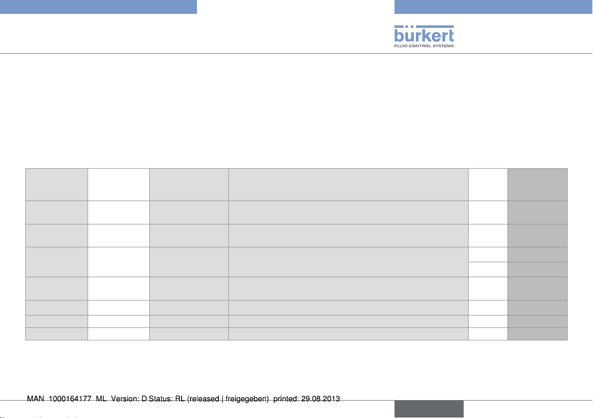
5.3. Available versions of the SE32 electronic module
The order codes of the S030 or S070 fittings can be taken from the related data sheet: refer to the data sheets to select the fitting suited to
your application.
SE32 version
Threshold
detector
Threshold
detector
Threshold
detector
Threshold
detector
Flowmeter 12-36 V DC 4-20 mA + Relay Male 8-pin M12 and male EN 175301-803 fixed connectors
Flowmeter 12-36 V DC 4-20 mA + Relay Male 5-pin M12 and male EN 175301-803 fixed connectors no 560402
Flowmeter 12-36 V DC 4-20 mA Male 5-pin M12 fixed connector no 560403
Supply
voltage
12-36 V DC Transistor, NPN EN 175301-803 male fixed connector
12-36 V DC Transistor, PNP EN 175301-803 male fixed connector
12-36 V DC Transistor, NPN
12-36 V DC Relay Male 5-pin M12 and male EN 175301-803 fixed connectors
Output Electrical connection UL Order code
Male 5-pin M12 fixed connector
and PNP
no 436474
no 434871
no 436473
yes 553431
no 436475
no 560547
English
7
Page 10
Technical data
Technical data
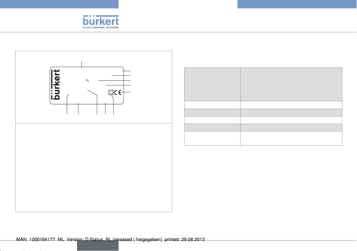
5.4. Description of the name plate
1
FLOW : SE32 HALL
SUPPLY:12-36V= 90mA
REL:230V 3A
PV:12-36V / 4-20mA
0.3-10m/s
S-N:1110
Made in France
00560547 W45LP
10 7
911
8
1. Measured process value and type of the electronic module
2. Type of sensor
3. Power supply; Max. current consumption
4. Data of the on/off output
5. Data of the current output
6. Conformity logo
7. Electrical protection class: double insulation
8. Manufacturing code
9. Measurement range of the flow rate
10. Order code
11. Serial number
Fig. 1: Name plate (example)
2
3
4
5
6
6. TECHNICAL DATA
6.1. Conditions of use
Ambient temperature
• 8032
• 8072
• UL device
Air humidity < 80%, non condensated
Height above sea level 2000 m max. (UL device)
Degree of pollution Degee 2 acc. to EN 61010-1 (UL device)
Installation class Class I acc. to UL 61010-1 (UL device)
Protection rating IP65 acc. to EN 60529, with connectors
6.2. Compliance to standards and
directives
The device conforms to the EC directives through the following
standards:
• EMC: EN 61000-6-2, EN 61000-6-3
• LVD: EN 61010-1
• Environnemental testing: Vibration: EN 60068-2-6, Shock:
EN 60068-2-27.
• Pressure: The S030 fitting complies with article 3 of §3 from
97/23/CE directive.
(in operation)
• -10°C...60°C
• 0°C...60°C
• 0°C...40°C
plugged-in and tightened or sealed
8
English
Page 11
Technical data
Technical data
Acc. to the 97/23/CE pressure directive, the fitting S030 can only
be used in the following cases (depending on max. pressure, pipe
diameter and fluid):
Type of fluid Conditions
Fluid group 1, par. 1.3.a only DN ≤ 25
Fluid group 2 par. 1.3.a DN ≤ 32
or DN > 32 and PNxDN ≤ 1000
Fluid group 1 par. 1.3.b PNxDN ≤ 2000
Fluid group 2 par. 1.3.b DN ≤ 200
The UL device, with order code 553431, for the United States of
America and Canada complies with the following standards:
• UL 61010-1
• CAN/CSA-C22.2 n° 61010-1.
6.3. General technical data
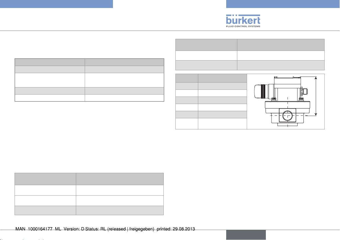
6.3.1. Mechanical data
Parts not exposed to the
fluid
Housing, cover Fibre glass reinforced polycarbonate
Fixed connectors PA
Material
Parts not exposed to the
fluid
Screws Stainless steel
O-ring seals FKM as standard (EDPM optional)
DN H with S070 fitting
15 85
25 100
40 117
50 135
80 175
100 176
Fig. 2: Dimension H [mm] of the 8072 depending on the S070
fitting diameter
Material
H
Front panel Polyester
English
9
Page 12
Technical data
Technical data
DN H with S030 fitting
06 80
08 80
15 85
20 82
H
25 83
32 86
40 90
50 96
65 96
Fig. 3: Dimension H [mm] of the 8032 depending on the S030
fitting diameter
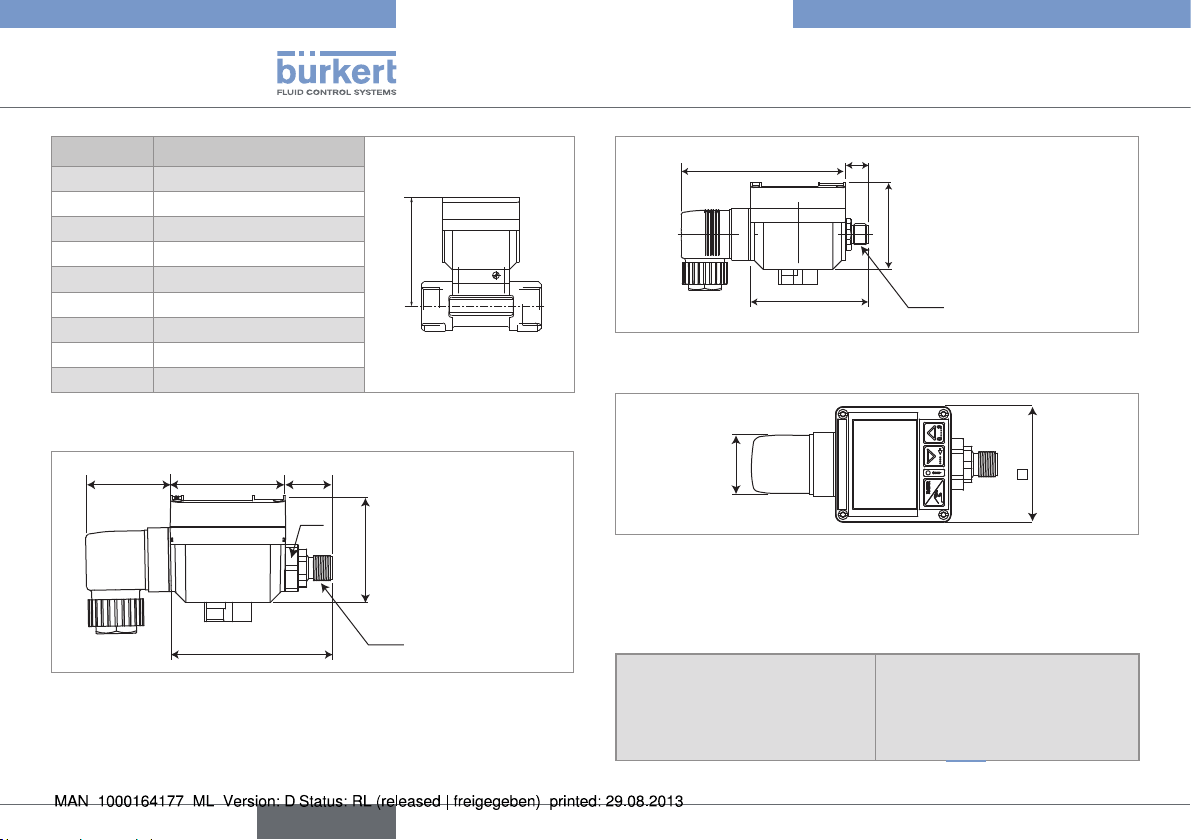
54 40
22
SW 22
50
76
5-pin M12
Fig. 4: Dimensions [mm] of the SE32 electronic module with a
5-pin M12 fixed connector
67.5
13.5
50
8-pin M12
94
Fig. 5: Dimensions [mm] of the SE32 electronic module with an
8-pin M12 fixed connector
30
54
Fig. 6: Dimensions [mm] of the SE32 electronic module, top
view
6.3.2. General data
Pipe diameter depends on the fitting used; The
appropriate diameter of an S030
fitting is determined using the
flow/DN/fluid velocity diagrams
in chap. 7.2.1).
10
English
Page 13
Technical data
Technical data
Type of fluid depends on the fitting used
(refer to the operating instructions of the fitting used)
Fluid viscosity depends on the fitting used
(refer to the operating instructions of the fitting used)
Rate of solid particles (8032
max. 1%
only)
Fluid temperature
• with fitting S030 in PVC
• with fitting S030 in PP
• with fitting S030 in stainless
• 0 to 50 °C (see Fig. 8)
• 0 to 80 °C (see Fig. 8)
• -15 to 100 °C (see Fig. 8)
steel, PVDF, or brass
• with S070 fitting, housing in
• max. 80 °C
aluminium
• with S070 fitting, housing in
• max. 100 °C
stainless steel
Fluid pressure
• 8032 with S030 fitting in
• PN16 max. (see Fig. 8)
metal
• 8032 with S030 fitting in
• PN10 max. (see Fig. 8)
plastic
• 8072 with fitting S070 with
• PN10 max.
flanges
• 8072 with any fitting S070
• PN55 max.
except S070 with flanges
Measurement range
• 8032
• 0.3 m/s to 10 m/s,
0.3 m/s corrresponds to a flow
rate of 0.5 l/min in a DN06
fitting
• 8072
• 2 to 1200 l/min, with a viscosity > 5 cps;
3 to 616 l/min, with a viscosity
< 5 cps;
Accuracy
• 8032 (see
Fig. 7)
• ±1 % of the full scale1), with
on site calibration or when
using the teach-in feature
or
± (1 % of the full scale1) + 3%
of the measured value), when
using the standard K factor
• 8072
• ±1% of the measured value
Repeatability
• 8032
• 8072
Linearity (8032 only) ±0.5 % of the full scale
• ±0.4% of the measured value
• ±0.03% of the measured
value
1)
Measuring element paddle-wheel of the S030 fitting
or oval gears of the S070 fitting
1)
Full scale = 10 m/s
English
11
Page 14
Technical data
Technical data
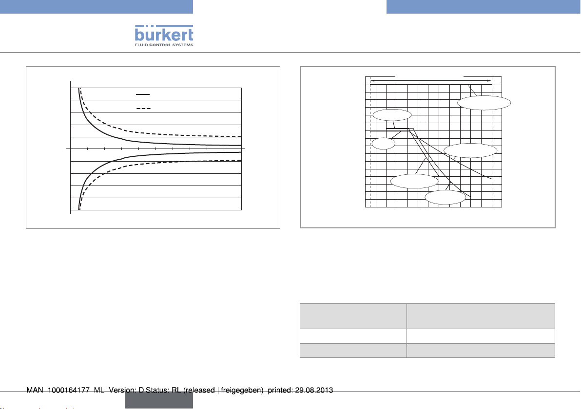
Max error %
20
16
12
8
4
-4
-8
-12
-16
-20
Measuring error - % of the
measurement
1 9
2 3 4 5 6 7 8 10
Fluid velocity in m/s
with a Teach-in procedure
With standard K factor of
the S030 fitting
Fig. 7: Accuracy of the measurements made by a 8032, when
using or not the Teach-in feature.
These values were determined in the following reference conditions:
medium = water, water and ambient temperatures 20 °C, min. upstream and
downstream distances respected, appropriate pipe dimensions
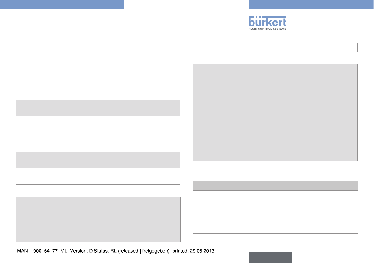
P [bar]
16
15
14
13
12
PVC + PP
11
10
9
PVDF
8
7
6
5
4
3
2
1
0
-15 0 +20 +40 +60 +80 +100
PVC (PN10)
A
Metal (PN16)
PVDF (PN10)
PP (PN10)
T [°C]
Fig. 8: Fluid temperature / pressure dependency of the 8032,
depending on the material the S030 fitting is made of
6.3.3. Electrical data
Table 1: Electrical data for threshold detectors
Installation class (overvoltage class)
Supply voltage 12-36 V DC
Dielectric strength 2300 V AC
2
12
English
Page 15
Technical data
Technical data
Current consumption
• Version with transistor
output
• Version with 1 single
output, relay or current
• version with 1 relay and
1 current outputs
Protection against polarity
reversal
Transistor output NPN and/or PNP, 700 mA max.,
Relay output 250 V AC, 3 A max, operation and
Protection against short
circuits
Table 2: Electrical data specific to the UL threshold detector
Characteristics of the
power source (not
supplied)
• 50 mA max.
• 70 mA max.
• 90 mA max.
yes
operation and thresholds can be
parametered
NPN output: 0,2-36 V DC,
PNP output: supply voltage
thresholds can be parametered
yes, for the transistor output
• Limited power source (in accordance
with § 9.3 of the UL 61010-1
standard)
• or class 2 type power source
(according to the 1310/1585 and
60950-1 standards)
Drain current 30-50 mA
Table 3: Electrical data for flowmeters
4-20 mA output
• Accuracy
• Wiring
• Loop resistance
• Galvanically insulated
• 4 mA adjustment
• 20 mA adjustment
• Response time (10% up to
90%)
• ±0.5%
• 4 wires
• 1300W at 36 V DC, 1000W at
30 V DC, 700 W at 24 V DC,
450 W at 18 V DC, 200W at
12 V DC
• yes
• between 3 and 5 mA
• between 18.5 and 21.5 mA
• 3 s with filter 2 (default setting)
6.3.4. Data of the cables and wires
Version Type of connector
Detector with
NPN transistor
output
Detector with
PNP transistor
output
EN 175301-803 female connector (type 2508,
supplied)
EN 175301-803 female connector (type 2508,
supplied)
English
13
Page 16
Installation and wiring
Installation and wiring
Version Type of connector
Detector with
Female 5-pin M12 connector (not supplied)
NPN/PNP transistor output
Detector with
relay output
Flowmeter with
relay output
EN175301-803 (type 2508 supplied) and 5-pin
M12 (not supplied) female connectors
EN 175301-803 (type 2508 supplied) and 8-pin
M12 (not supplied) or 5-pin M12 (not supplied)
female connectors
Flowmeter
Female 5-pin M12 connector (not supplied)
without relay
output
Type of connector Cable type
M12 with order code
917116
• shielded
• 3 to 6.5 mm in diameter
• with wires with a max. cross section
of 0,75 mm
2508 with order code
438811
• shielded
• 6 to 7 mm in diameter
• with wires with a cross section of
between 0.14 and 0.5 mm
7. INSTALLATION AND WIRING
7.1. Safety information
DANGER
Risk of injury due to high pressure in the installation
• Stop the circulation of fluid, cut off the pressure and drain the
pipe before loosening the process connections.
Risk of injury due to high fluid temperatures.
• Use safety gloves to handle the device.
• Stop the circulation of fluid and drain the pipe before loosening
the process connections.
Risk of injury due to the nature of the fluid.
• Respect the regulations on accident prevention and safety relating to the use of aggressive fluids.
Risk of injury due to electrical voltage.
2
2
• Shut down the electrical power source of all the conductors and
isolate it before carrying out work on the system.
• Do not unscrew the cover of a powered device.
• Observe all applicable accident protection and safety guidelines
for electrical equipment.
14
English
Page 17
Installation and wiring
Installation and wiring
WARNING
Risk of injury due to nonconforming installation.
• The electrical and fluid installation can only be carried out by
qualified and skilled staff with the appropriate tools.
• Install appropriate safety devices (correctly rated fuse and/or
circuit-breaker).
• Respect the assembly instructions for the fitting used.
Risk of injury due to unintentional switch on of power supply
or uncontrolled restarting of the installation.
• Take appropriate measures to avoid unintentional activation of
the installation.
• Guarantee a set or controlled restarting of the process subsequent to any intervention on the device.
To ensure that the device runs correctly, plug in and tighten
the connectors.
7.2. Installation onto the pipe
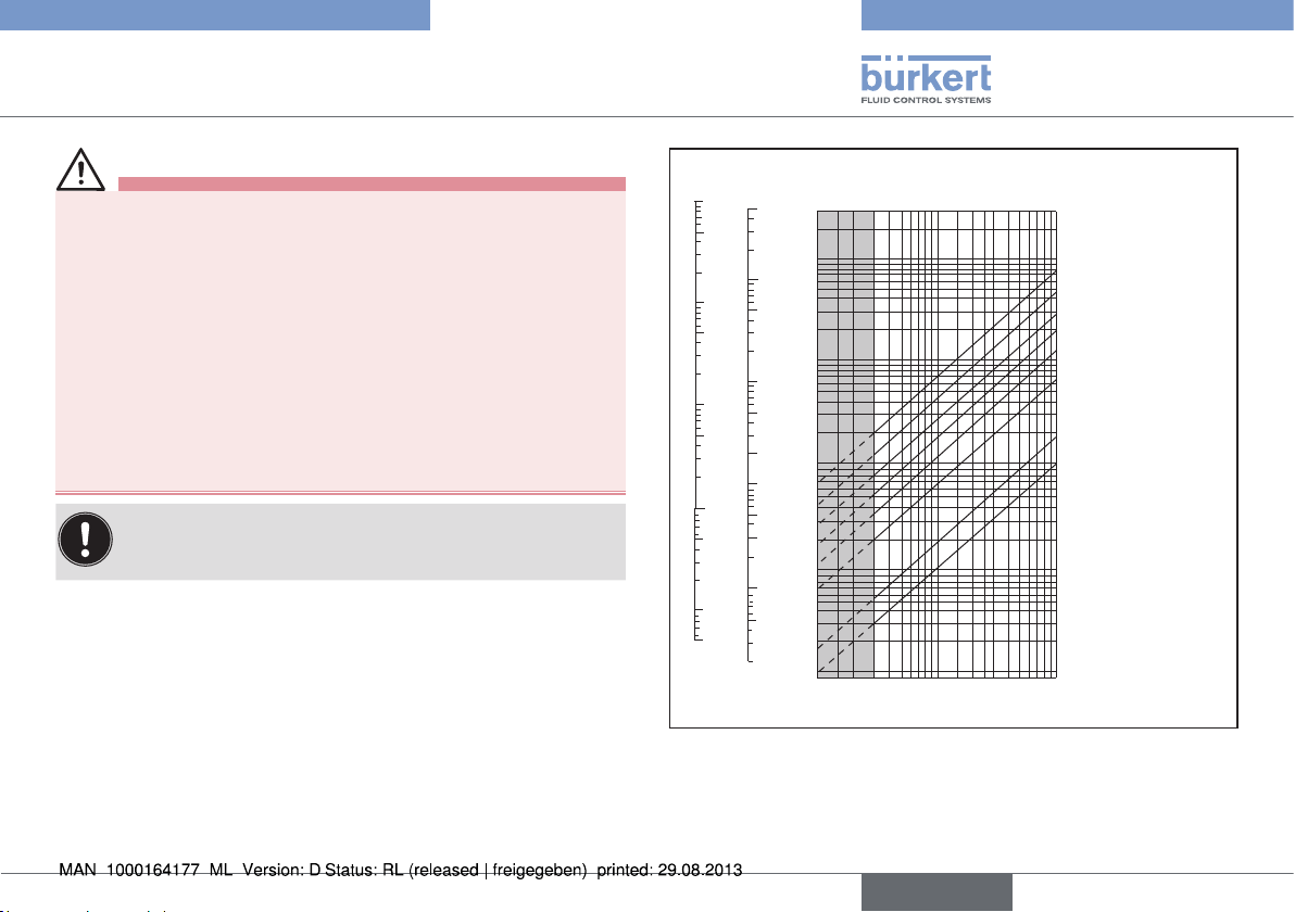
7.2.1. Diagrams
These diagrams are used to determine the DN of the fitting (only
for a threshold detector / flowmeter 8032) appropriate to the application, according to the fluid velocity and the flow rate.
Flow rate
l/s
100
50
10
5
1
0.5
0.1
0.05
0.01
0.005
l/min
5000
1000
500
100
50
20
10
5
3
2
1
0.5
0.3
0.2
m
200
100
50
20
10
0.5
0.2
0.1
0.05
0.02
0.01
3
/h
5
2
1
0.1 0.3 0.5 1 2 3 5 100.2
Flow velocity
DN 50 (DN65)*
DN 40 (DN50)*
DN 32 (DN40)*
DN 25 (DN32)*
DN 20 (DN25)*
DN 15 (DN15 / DN20)*
DN 08
DN 06
m/s
English
15
Page 18
Installation and wiring
Installation and wiring
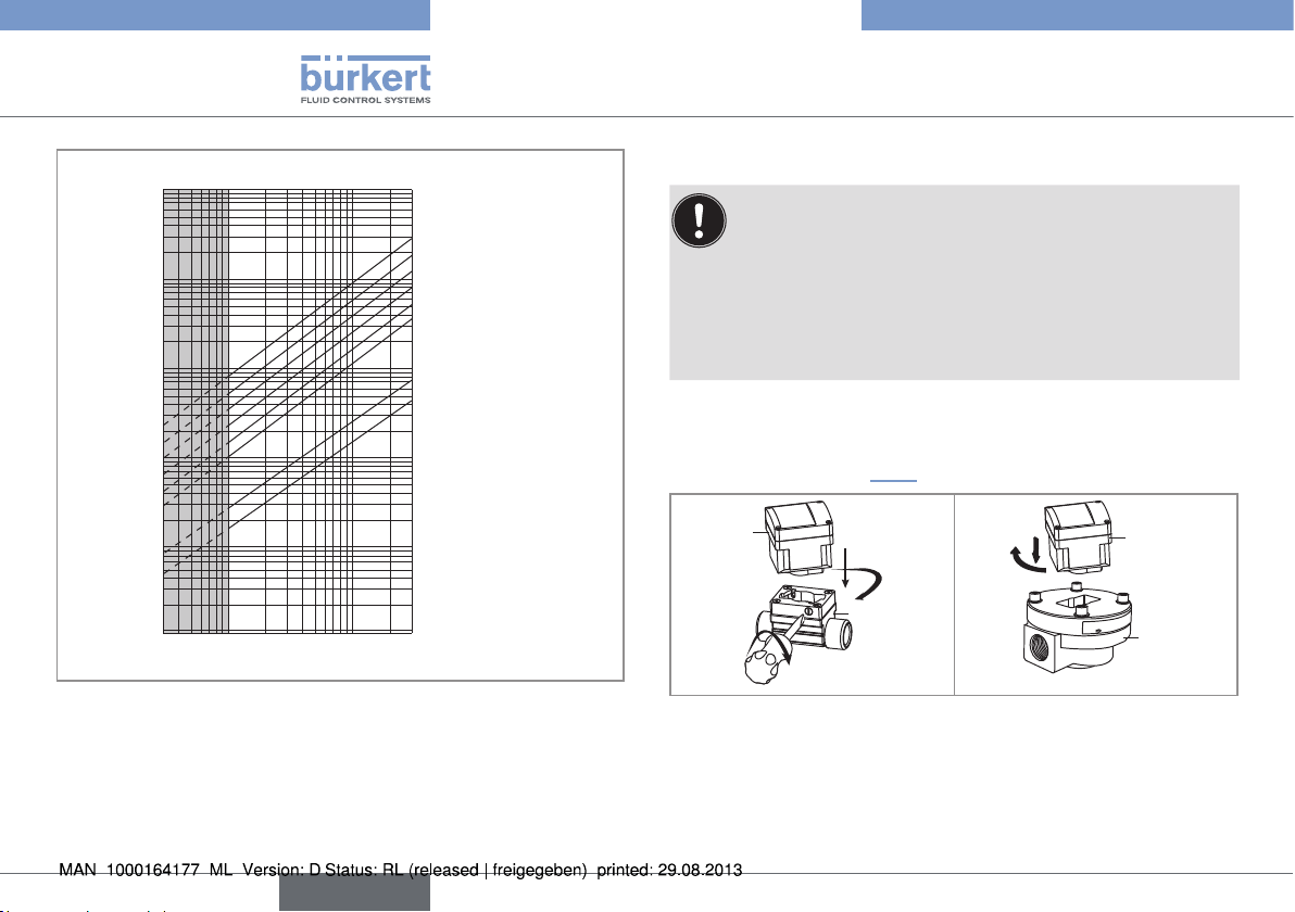
gpm
1000
Flow rate
500
200
100
50
20
10
5
2
1
0.5
0.2
0.1
0.05
0.02
0.01
DN50 (DN65)*
DN40 (DN50)*
DN32 (DN40)*
DN25 (DN32)*
DN20 (DN25)*
DN15 (DN15 / DN20)*
DN08
DN06
fps
30200.3 0.5 1 2 3 5 10
Flow velocity
* for the following fittings:
- with external threads acc. to SMS 1145.
- with weld ends acc. to SMS 3008, BS 4825 / ASME BPE or
DIN 11850 Rg2.
- with clamp connections acc. to SMS 3017 / ISO 2852 or
BS 4825 / ASME BPE or DIN 32676.
7.2.2. Assembly of the 8032 / 8072
The electronic module SE32 only detects one rotation
direction of the oval gears of a fitting S070.
• If the 8072 does not run properly, once assembled and
energized, do the following:
→ remove the SE32 from the S070,
→ turn the electronic module SE32 by 180°,
→ insert the SE32 back into the S070.
→ Install the fitting in the pipe according to the installation instruc-
tions provided with the fitting.
→ To assemble the electronic module with the fitting, follow the
instructions given in Fig. 9.
SE32
1
2
S030
3
Fig. 9: Assembling the SE32 with the fitting S030 or S070
1
2
SE32
FLOW
S070
16
English
Page 19
Installation and wiring
Installation and wiring
7.3. Wiring
DANGER
Risk of injury due to electrical voltage
• Shut down the electrical power source of all the conductors and
isolate it before carrying out work on the system.
• Observe all applicable accident protection and safety guidelines
for electrical equipment.
• Use shielded cables with a temperature limit of 80 °C
minimum.
• Use a high quality electrical power supply, filtered and
regulated.
• Protect the power supply by means of a 1 A fuse and a
switch.
• Protect the power supply of each transistor by means of a
125 mA fuse.
• Protect the relays by means of a max. 3 A fuse and a
circuit breaker (depending on the process).
• Do not apply both a dangerous voltage and a safety extralow voltage to the relays.
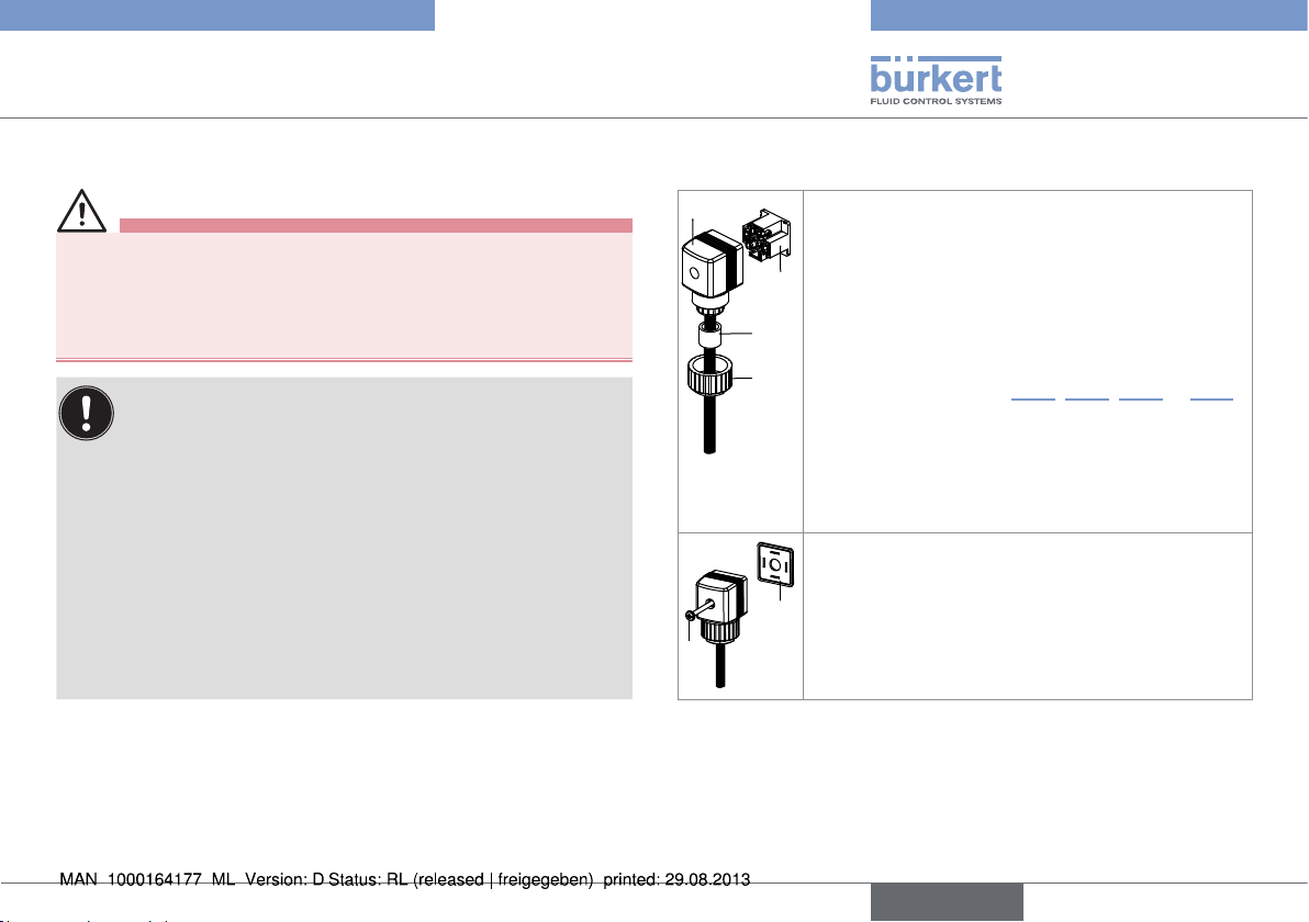
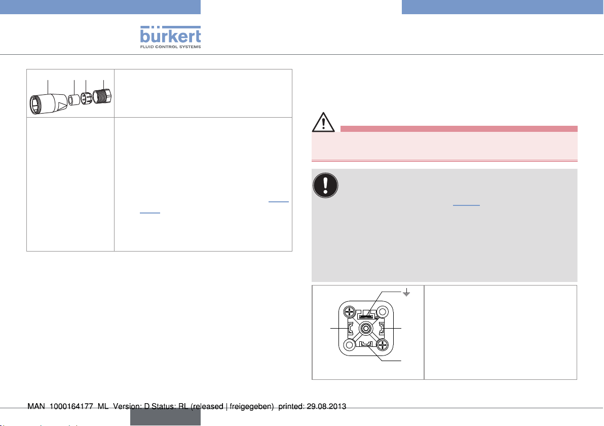
7.3.1. Assembling the connectors
2
→ Unscrew the nut [1] of the cable gland.
→ Remove the terminal block [3] from the housing
[2].
3
→ Insert the cable through the nut [1] then through
the gasket [4], through the cable gland and
4
1
finally through the housing [2].
→ Make the connections to the screw terminal
block [3] (see chap. 7.3.2, 7.3.4, 7.3.6 or 7.3.7).
→ Position the terminal block [3] in steps of 90°
then put it back into the housing [2], pulling
gently on the cable so that the wires do not
clutter the housing.
→ Tighten the nut [1] of the cable gland.
→ Place the seal [5] between the connector and
the EN175301-803 fixed connector on the
device and then plug the 2508 connector into
5
the fixed connector.
6
Fig. 10: Assembling the female connector type 2508 (supplied)
→ Insert and then tighten the screw [6] to ensure
tightness and correct electrical contact.
English
17
Page 20
Installation and wiring
Installation and wiring
4 3 2 1
→ Unscrew the nut [1] on the body [4].
→ Insert the cable into the nut [1], the cable
clamp [2] and the seal [3], and then into
the body [4].
→ Strip 20 mm of the cable.
→ Cut the central wire (earth) so that its
length is equal to 11.5 mm.
→ Expose 5.5 mm of the wires on the
stripped cable.
→ Insert each wire into the appropriate pin
on the terminal block [5] (see chap. 7.3.3
to 7.3.7).
→ Screw the terminal block [5] once wired
to the body [4]
→ Tighten the connector nut [1].
Fig. 11: Assembling an M12 female connector (not supplied )
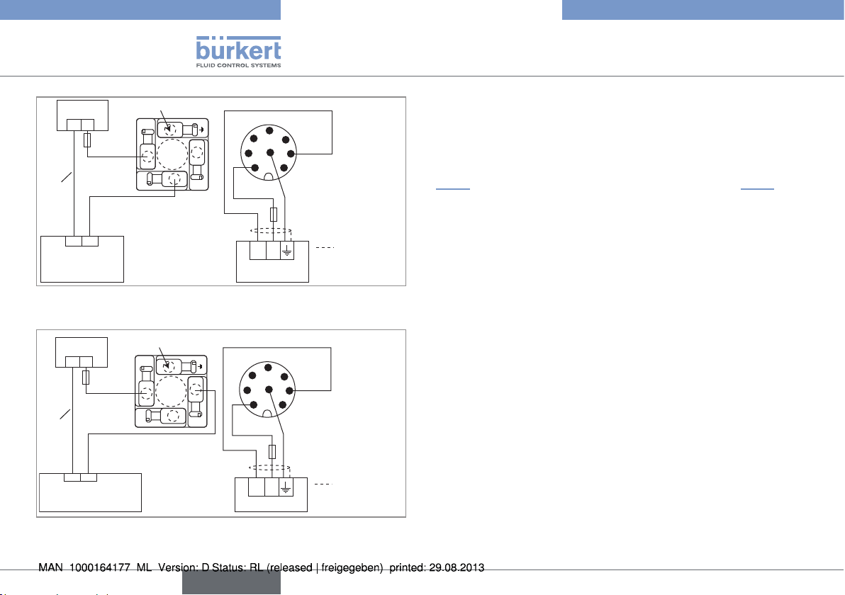
7.3.2. Wiring a version with transistor
output and EN175301-803 male fixed
connector
DANGER
Risk of injury due to electrical voltage
• Always plug in and tighten the connectors correctly.
The device is not tight when the EN 175301-803 fixed
connector is not wired:
→ Unscrew the nut [1] (see Fig. 10) on the 2508 female
connector supplied with the device.
→ Insert the plug with order code 444509, supplied with
the device, into the cable gland.
→ Screw the nut again.
→ Plug the sealed 2508 connector onto the
EN 175301-803 fixed connector.
1: V+ (12-36 V DC)
2
1
1
3
2: Transistor output (NPN or PNP)
2
3: 0 V DC
4: Functional earth
3
18
Fig. 12: Pin assignment of the EN175301-803 fixed connector
English
Page 21
Installation and wiring
Installation and wiring
Load
(solenoid valve,
for example)
+-
Power cable shield
(*)
1
V+
PNP transistor
2
output
+ -
12-36 V DC
3
0 V DC
Power supply
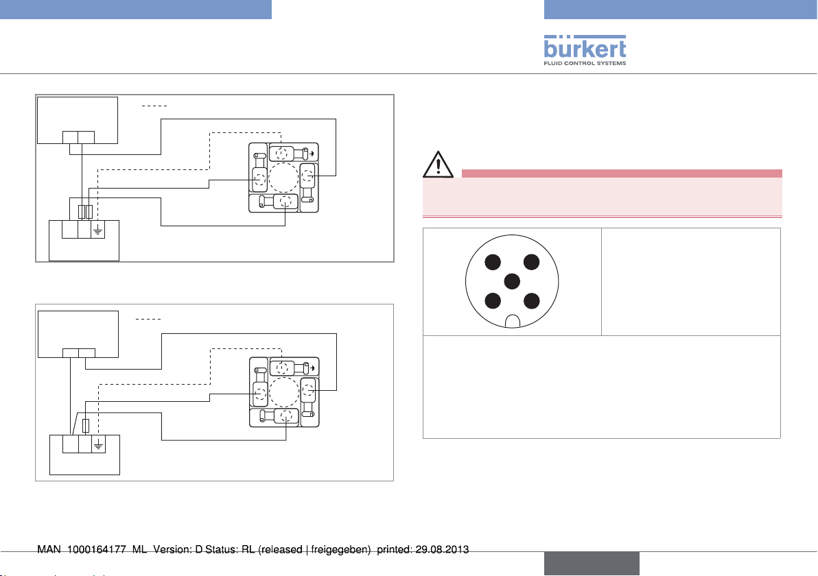
Fig. 13: NPN wiring of the transistor output of a version with
EN 175301-803 fixed connector
Load
(solenoid valve,
for example)
+-
+ -
12-36 V DC
Power supply
Power cable shield
V+
1
3
0 V DC
(*)
NPN transistor
output
2
Fig. 14: PNP wiring of the transistor output of a version with
EN 175301-803 fixed connector
(*) Functional earth
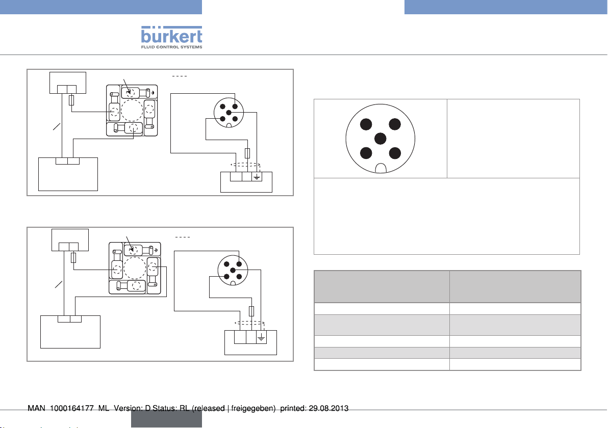
7.3.3. Wiring a version with 2 transistor
outputs and a 5-pin M12 male fixed
connector
DANGER
Risk of injury due to electrical voltage
• Always plug in and tighten the connectors correctly.
1: V+ (12-36 V DC)
4 3
5
1 2
2: NPN transistor output
3: 0 V DC
4: PNP transistor output
5: Functional earth
The position of the 5-pin M12 fixed connector is adjustable:
→ Unscrew the locknut.
→ Turn the fixed connector to the desired position, by 360° max. to
prevent the cables from twisting inside the housing.
→ Tighten the locknut using a spanner, while keeping the fixed
connector in the desired position.
Fig. 15: Allocation of the pins on the 5-pin M12 fixed connector
English
19
Page 22
12-36 V DC
Installation and wiring
Installation and wiring
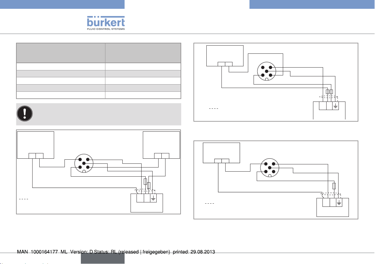
Pin of the M12 female cable
available as accessory
Colour of the wire (signal)
equipment (order code 438680)
1 brown (12-36 V DC)
2 white (NPN transistor output)
3 blue (0 V DC)
4 black (PNP transistor output)
5 grey (functional earth)
When both transistor outputs are wired, they operate with
the same settings made within the OUT function.
Load 1
(wired in PNP
mode)
5
1 2
3 4
brown
blue
grey
+ -+ -
black
Load 2
(wired in NPN
mode)
white
(*)
Power cable shield
Power supply
+ -
12-36 V DC
Fig. 16: Wiring both transistor outputs on a version with a 5-pin
M12 fixed connector
Load
(solenoid valve,
for example)
+-
white
5
1 2
3 4
blue
grey
brown
(*)
Power cable shield
Power supply
+ -
Fig. 17: Wiring of the NPN transistor output of a version with a
5-pin M12 fixed connector
Load
(solenoid valve,
for example)
+-
black
5
1 2
3 4
blue
grey
brown
(*)
Power cable shield
Power supply
+ -
12-36 V DC
Fig. 18: Wiring of the NPN transistor output of a version with a
5-pin M12 fixed connector
(*) Functional earth
20
English
Page 23
Installation and wiring
Installation and wiring
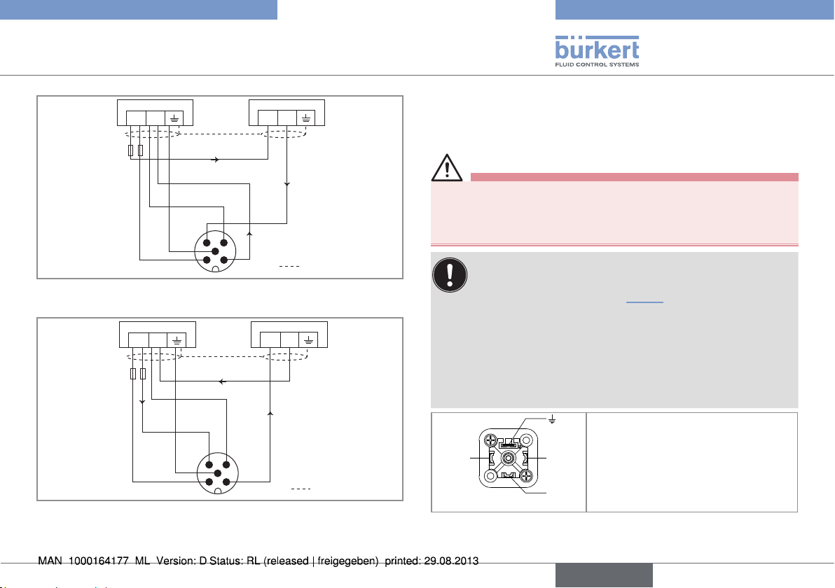
7.3.4. Wiring of the version with a single
relay output
WARNING
Shock hazard due to the voltage at the relay terminals, which
is higher than 48V.
• Before powering the device, always check that the connectors
are correctly plugged-in and tightened.
The device is not tight when the EN 175301-803 fixed
connector is not wired:
→ Unscrew the nut [1] (see Fig. 10) on the 2508 female
connector supplied with the device.
→ Insert the plug with order code 444509, supplied with
the device, into the cable gland.
→ Screw the nut back.
→ Plug the sealed 2508 connector onto the
EN 175301-803 fixed connector.
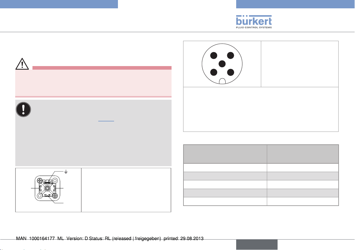
1: Common
2
1
1
3
2
3
Fig. 19: Pin assignment on the EN 175301-803 fixed connector
2: Relay, normally closed (NC)
3: Relay, normally open (NO)
4: Not connected
4 3
5
1 2
1: V+ (12-36 V DC)
2: not connected
3: 0 V DC
4: not connected
5: Functional earth
The position of the 5-pin M12 fixed connector is adjustable:
→ Unscrew the locknut.
→ Turn the fixed connector to the desired position, by 360° max. to
prevent the cables from twisting inside the housing.
→ Tighten the locknut using a spanner, while keeping the fixed
connector in the desired position.
Fig. 20: Pin assignment of the 5-pin M12 fixed connector
Pin of the M12 female cable
available as accessory
equipment (order code 438680)
1 brown (V+)
2 not connected
3 blue (0 V DC)
4 not connected
5 grey (functional earth)
(1) Use a voltage limiter depending on the load selected, e.g. for the solenoid
valve, an EN 175301-803 connector with integrated varistor.
(*) Functional earth
Colour of the wire (signal)
English
21
Page 24
Installation and wiring
Installation and wiring
250 V AC
L
N
(1)
Load
(solenoid valve,
for example)
not connected
1
3
Relay output, normally open
(NO)
2
Power cable shield
blue
Power supply
3 4
5
1 2
brown
12-36 V DC
grey
(*)
+ -
Fig. 21: NO wiring of the relay output of a version with one 5-pin
M12 and one EN 175301-803 fixed connectors
250 V AC
L
N
(1)
Load
(solenoid valve,
for example)
not connected
1
3
Relay output, normally
closed (NC)
2
Power cable shield
blue
1 2
Power supply
3 4
grey
5
brown
(*)
+-
12-36 V DC
Fig. 22: NC wiring of the relay output of a version with one 5-pin
M12 and one EN 175301-803 fixed connectors
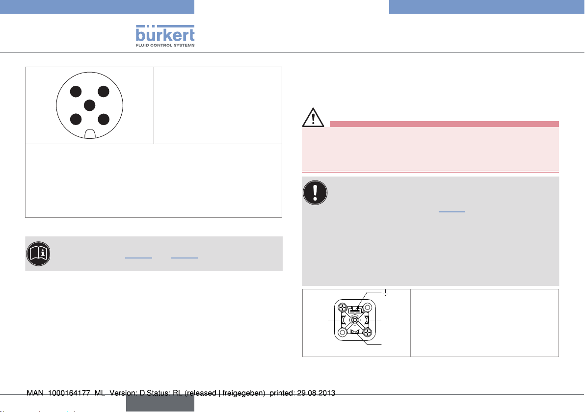
7.3.5. Wiring of the version with a single
current output
4 3
5
1 2
The position of the 5-pin M12 fixed connector is adjustable:
1: V+ (12-36 V DC)
2: Negative 4-20 mA output
3: 0 V DC
4: Positive 4-20 mA output
5: Functional earth
→ Unscrew the locknut.
→ Turn the fixed connector to the desired position, by 360° max. to
prevent the cables from twisting inside the housing.
→ Tighten the locknut using a spanner, while keeping the fixed
connector in the desired position.
Fig. 23: Pin assignment of the 5-pin M12 fixed connector
Pin of the M12 female cable
available as accessory
equipment (order code 438680)
1 brown (V+)
2
3 blue (0 V DC)
4 black (positive 4-20 mA output)
5 grey (functional earth)
The current output can be connected in either sourcing or sinking
mode.
Colour of the wire (signal)
white (negative 4-20 mA
output)
22
English
Page 25
Installation and wiring
Installation and wiring
Power supply
12-36 V DC
+
+
(*)
-
4-20mA input
(at external
instrument)
i
brown
grey
white
blue
4
5
1 2
3
i
black
i
shield
Fig. 24: Wiring of the current output, in sinking mode, of a
version with a single 5-pin M12 fixed connector
Power supply
12-36 V DC
+
+
(*)
-
4-20mA input
(at external
instrument)
i
black
4
grey
1 2
blue
i
white
3
5
shield
i
brown
Fig. 25: Wiring of the current output, in sourcing mode, of a
version with a single 5-pin M12 fixed connector
(*) Functional earth
7.3.6. Wiring the version with both relay
and current outputs (5-pin M12 fixed
connector)
WARNING
Shock hazard due to the voltage at the relay terminals, which
is higher than 48V.
• Before powering the device, always check that the connectors
are correctly plugged-in and tightened.
The device is not tight when the EN 175301-803 fixed
connector is not wired:
→ Unscrew the nut [1] (see Fig. 10) on the 2508 female
connector supplied with the device.
→ Insert the plug with order code 444509, supplied with
the device, into the cable gland.
→ Screw the nut back.
→ Plug the sealed 2508 connector onto the
EN 175301-803 fixed connector.
1: Common
2
1
1
3
2
3
Fig. 26: Pin assignment on the EN 175301-803 fixed connector
2: Relay, normally closed (NC)
3: Relay, normally open (NO)
4: not connected
English
23
Page 26
Installation and wiring
Installation and wiring
1: V+ (12-36 V DC)
4 3
5
1 2
2: Negative 4-20 mA output
3: 0 V DC
4: Positive 4-20 mA output
5: Functional earth
The position of the 5-pin M12 fixed connector is adjustable:
→ Unscrew the locknut.
→ Turn the fixed connector to the desired position, by 360° max. to
prevent the cables from twisting inside the housing.
→ Tighten the locknut using a spanner, while keeping the fixed con-
nector in the desired position.
Fig. 27: Pin assignment of the 5-pin M12 fixed connector
The current output can be connected in either sourcing or
sinking mode. See Fig. 30 and Fig. 31 for the related wiring
charts.
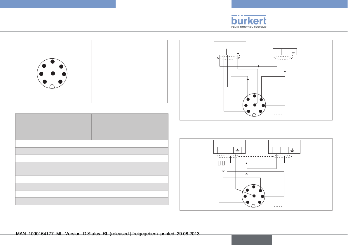
7.3.7. Wiring the version with relay and
current outputs (8-pin M12 fixed
connector)
WARNING
Shock hazard due to the voltage at the relay terminals, which
is higher than 48V.
• Before powering the device, always check that the connectors
are correctly plugged-in and tightened.
The device is not tight when the EN 175301-803 fixed
connector is not wired:
→ Unscrew the nut [1] (see Fig. 10) on the 2508 female
connector supplied with the device.
→ Insert the plug with order code 444509, supplied with
the device, into the cable gland.
→ Screw the nut back.
→ Plug the sealed 2508 connector onto the
EN 175301-803 fixed connector.
1: Common
2
1
1
3
2: Relay, normally closed (NC)
2
3: Relay, normally open (NO)
3
4: Not connected
24
Fig. 28: Pin assignment on the EN 175301-803 fixed connector
English
Page 27
Installation and wiring
Installation and wiring
1: V+ (12-36 V DC)
5
6
4
2: Not connected
3: 0 V DC
4: Positive 4-20 mA output
8
7
1
3
2
5: Not connected
6: Negative 4-20 mA output
7: Not connected
8: Functional earth
Fig. 29: Allocation of the pins on the M12, 8-pin fixed connector
Pin of the 8-pin M12 female
Colour of the wire (signal)
cable available as an
accessory equipment (order
code 444800)
1 white (12-36 V DC)
2 not connected
3 green (0 V DC)
4 yellow (positive 4-20 mA
output)
5 not connected
6 pink (negative 4-20 mA output)
7 not connected
8 grey (functional earth)
The current output can be connected in either sourcing or sinking mode.
Power supply
12-36 V DC
+
(*)
+
-
4-20mA input
(at external
instrument)
i
i
green
shield
white
6
7
1 2
yellowpink
grey
i
5
4
3
8
Fig. 30: Wiring of the current output, in sinking mode, of a
version with an 8-pin M12 fixed connector
Power supply
12-36 V DC
+
(*)
+
-
4-20mA input
(at external
instrument)
i
6
7
1 2
pink
i
5
yellow
4
green
3
8
shield
i
grey
white
Fig. 31: Wiring of the current output, in sourcing mode, of a
version with an 8-pin M12 fixed connector
English
25
Page 28
Installation and wiring
Installation and wiring
250 V AC
L
N
(1)
Relay output, normally open
(NO)
Load (solenoid
valve, for example)
not connected
1
3
Power supply (2)
6
7
2
1 2
white
12-36 V DC
green
5
4
3
8
grey
(*)
+ -
Power cable
shield
Fig. 32: NO wiring of the relay output of a version with an 8-pin
M12 fixed connector
250 V AC
L
N
(1)
Relay output, normally
closed (NC)
Load (solenoid valve,
for example)
not connected
1
3
Power supply (2)
6
7
2
1 2
white
12-36 V DC
green
5
4
3
8
grey
(*)
+ -
Power cable
shield
Fig. 33: NC wiring of the relay output of a version with an 8-pin
M12 fixed connector
(*) Functional earth
(1) Use a voltage limiter depending on the load selected, e.g. for the solenoid
valve, an EN 175301-803 connector with integrated varistor.
(2) If the current output is needed, wire the 8-pin M12 connector acc. to
Fig. 30 if the current output is wired in sinking mode, or acc. to Fig. 31 if the
current ouput is wired in sourcing mode.
26
English
Page 29
Commissioning
Commissioning
8. COMMISSIONING
8.1. Safety information
WARNING
Danger due to nonconforming commissioning.
Nonconforming commissioning could lead to injuries and damage
the device and its surroundings.
• Before commissioning, make sure that the staff in charge have
read and fully understood the contents of the manual.
• In particular, observe the safety recommendations and intended
use.
• The device/installation must only be commissioned by suitably
trained staff.
NOTE
Risk of damage to the device due to the environment
• Protect this device against electromagnetic interference,
ultraviolet rays and, when installed outdoors, the effects of the
climatic conditions.
• When the device is switched on and the cover is open,
protection against electric shock is no longer guaranteed.
• Check the chemical compatibility between the fluid to
be measured and the materials from which the device is
made exposed to it.
9. ADJUSTMENT AND
FUNCTIONS
9.1. Safety information
DANGER
Risk of injury due to electrical voltage
• Observe all applicable accident protection and safety guidelines
for electrical equipment.
WARNING
Risk of injury due to nonconforming adjustment.
Nonconforming adjustment could lead to injuries and damage the
device and its surroundings.
• The operators in charge of adjustment must have read and
understood the contents of this manual.
• In particular, observe the safety recommendations and intended
use.
• The device/installation must only be adjusted by suitably trained
staff.
• Before commissioning the device, enter the K factor of the fitting used. See chap. 9.4 and 9.5.
English
27
Page 30
Adjustment and functions
Adjustment and functions
9.2. Operating levels
All settings may influence the correct running of the
process.
• Note the values of the parameters set in the table at chap.
9.8.
The flow threshold detector / flowmeter 8032/8072 has 2 operating
levels: the Process level and the Configuration level.
The Configuration level comprises the Parameters and Test menus.
Operating level Functions
Process • To read out:
- the measured flow rate
- the switching thresholds
- the value of the 4-20 mA output (flowmeter
only)
• To access the Parameters and Test menus of
the Configuration level
Operating level Functions
Configuration
- Parameters
menu
Configuration Test menu
• To make the settings needed for operation:
- flow rate unit
- transistor or relay output
- filter
- bar graph
- K factor
- 4-20 mA current output (flowmeter only)
• To make the following additional settings:
- backlighting
- access code to the Parameters and Test
menus.
• To test the configuration made in the Parameters menu with entering of a theoretical value.
• To read the frequency of the measured signal.
• To adjust the 4-20 mA output.
28
English
Page 31

Adjustment and functions
Adjustment and functions
9.3. Description of the display and
the operating keys
The display is used to:
• read the value of certain parameters such as the measured flow
rate;
• parameterize the device by means of 3 keys;
• read the configuration of the device;
• get notification of some events.
• To change the value (0...9)
0......9
Back key
Next key
ENTER
Confirm key
of the selected digit.
• To go back to the previous
function.
• To select the digit at the
left;
• To go to the next function.
• To confirm the function
displayed;
• To confirm the parameters
set.
Bar graph running in each
mode, except during a
teach-in procedure.
O
U
T
Shows the status of the on/
off output (red LED).
Shows if the relay is open or
closed.
Means that the access to
the Parameters and Test
menus is protected through
a code.
Fig. 34: Description of the keys and icons
9.4. Process level
The use and setting of the access code to the Parameters
and Test menus are defined within the Parameters menu.
Display Displays...
Dispaly A ...the measured flow rate
Display B (only flowmeters) ...the value of the 4-20 mA output.
Display C ...the value of the low switching
threshold (
Display D ...the value of the high switching
threshold (
O LO).
O HI).
English
29
Page 32

Display A
Display B
Display C
Display D
0......9
Process level
1
0.615
l/s
12.56
MA
0.200
OLO
1.000
OHI
(by default)
Press the keys simultaneously
0......9
0......9
+
more than 5 s
ENTER
+
> 5 s
ENTER
+
> 5 s
> 5 s
+
ENTER
OFF
Status of
function
CODE?
Status of
function CODE?
OFF
(by default)
ON
ON
0000
0......9
0000
0......9
CODE
CODE
Adjustment and functions
Adjustment and functions
ENTER
ENTER
Code
OK?
Code
OK?
access to the Param-
2
eters menu (see chap.
9.5)
3
access to the Test
menu (see chap. 9.6)
30
English
Page 33

Adjustment and functions
Adjustment and functions
9.5. Configuration level - Parameters menu
All settings may influence the correct running of the process.
→ Note the values of the parameters set in the table at chap. 9.8.
Function Description of the function
UNIT (see chap. 9.5.1) To select the unit of the flow rate.
KFAC (see chap. 9.5.2) To enter the K factor of the fitting used or have it determined. The K factor is specific to each fitting. It is used by
the device to convert the measured signal into a flow rate.
OUT (see chap. 9.5.3) • To select:
- the operation of the transistor or relay output (Hysteresis or Window);
- whether the operation is inverted or not.
• To set:
- the high (
- the time delay before switching in seconds (
mA (see chap. 9.5.4) To set the flow rate range associated to the 4-20 mA output.
FILT (see chap. 9.5.5) • To choose the filter of the displayed flow rate.
Filter 0 means that flow rate variations are displayed.
Filter 9 means that flow rate variations are attenuated to the maximum.
BRGR (see chap. 9.5.6)
BKLG (see chap. 9.5.7) To deactivate the backlighting of the display, or adjust its intensity and set the time-out after which it goes off.
CODE (see chap. 9.5.8) To activate the use of the access code to the Parameters and Test menus. By default, the access code is not
END (see chap. 9.5.9) To go back to the Process level by saving or not the settings made.
To enter the flow rate range, minimum (
requested.
O HI) and low (O LO ) switching thresholds;
DEL).
BG LO) and maximum (B G HI) values, associated to the bar graph.
English
31
Page 34

9.5.1. Selecting the unit of the flow rate
WARNING
If the flow rate unit is modified, also modify the transistor or relay
switching thresholds (function OUT), the threshold values of the
bar graph (function BRGR) and the flow rate range associated to
the current output (function mA).
2
ENTER
UNIT
To function KFAC
0......9
GA/H
L/S
UNIT
ENTER
.
.
.
ENTER
2
Refer to chap. 9.4 to access
the Parameters menu.
→ Select the desired unit of the flow rate.
Adjustment and functions
Adjustment and functions
32
English
Page 35

Adjustment and functions
Adjustment and functions
9.5.2. Entering the K factor or having it determined by teach-in
During the whole teach-in procedure, the outputs are frozen to the status they had at the start of the teach-in.
• Entering the K factor of the fitting used:
KFAC
ENTER
0......9
NO
TEAC
YES
TEAC
ENTER
ENTER
TEAC
49.03
KFAC
0......9
ENTER
ENTER
*
200.0
0......9
VOL
→ select "NO TEAC",
→ press key "ENTER",
→ In the KFAC parameter, enter the K factor of the
ENTER
49.03
ENTER
KFAC
*
fitting used, in pulse/litre (value between 0,001 and
9999). Find the K factor within the operating instructions of the fitting.
• Determining the K factor by means of a teach-in
procedure:
To function OUT
→ install the 8032 / 8072 in series with a valve, for
instance, then
→ fill a tank with x litres capacity (200 litres for
* to move the decimal point, simultaneously press keys
0......9
and
example).
→ select "YES TEAC",
→ press key "ENTER",
→ open the valve: message "TEAC" blinks.
→ when the tank if full, press again key "ENTER".
→ enter the volume of liquid that has passed through
the circuit (in the unit displayed alternately with the
message "VOL"): the device calculates the K factor
and displays it.
English
33
Page 36

9.5.3. Configuring the relay or transistor output
Adjustment and functions
Adjustment and functions
0......9
01
DEL
* to move the decimal
point, simultaneously
press keys
0......9
and
OUT
ENTER
0......9
MODE
MODE
ENTER
ENTER
0.200
OLO
0......9
*
no
OHI>
OLO
1.000
0......9
*
OHI
ENTER ENTER
0......9
NO
ENTER ENTER
inv
ENTER
YES
inv
yes
To function "mA"
Hysteresis operation
The change of state is done when a threshold is detected (increasing flow rate:high threshold (OHI) to be detected, decreasing flow rate: low
threshold (OLO) to be detected).
Contact
ON
OFF
Not inverted
OLO OHI
Flow
rate
Contact
ON
OFF
Inverted
OLO OHI
Flow
rate
Fig. 35: Hysteresis operation of the transistor output
34
English
Page 37

Adjustment and functions
Adjustment and functions
Window operation
The change of state is done whenever one of the thresholds is
detected.
ON
OFF
Not invertedContact
OLO OHI
Flow
rate
Contact
ON
OFF
Inverted
OLO OHI
Flow
rate
Fig. 36: Window operation of the transistor output
The time delay (DEL) is valid for both output thresholds. switching
is only done if one of the thresholds (OHI - OLO) is exceeded for a
duration longer than this time delay.
Flow rate
OHI
OLO
2 s
2 s
2 s
OUT
Hysteresis operation
DEL = 0 s
DEL = 2 s
Window operation
DEL = 0 s
DEL = 2 s
Not inverted
Not inverted
Not inverted
Not inverted
Inverted
Inverted
Inverted
Inverted
ON
OFF
ON
OFF
ON
OFF
ON
OFF
ON
OFF
ON
OFF
ON
OFF
ON
OFF
Fig. 37: Examples for the behaviour of the transistor or relay
output of a 8032 / 8072, depending on the flow rate and
the operation chosen.
t
English
35
Page 38

ENTER
0......9
*
0......9
*
ENTER
ENTER
Adjustment and functions
Adjustment and functions
9.5.4. Setting the flow rate range
associated to the 4-20 mA output
The 4-20 mA output provides an electrical current, the value of
which reflects the flow rate measured by the device.
• The signal may be inverted, i.e. the flow rate value associated to the
20-mA current is lower than the one associated to the 4-mA current.
• The current output gives a 22-mA current when the device shows
an operating error.
mA
20
4
20 180
Fig. 38: Example of relation between the measuring range and
the current output
MA
To function "FILT"
→ Enter the flow rate values, in the unit that has been chosen in the
0.200
4ma
1.000
UNIT parameter, related to the 4-20-mA current range.
20ma
l/min
* to move the
decimal point,
simultaneously
press keys
0......9
and
9.5.5. Choosing the filter of the flow rate
FILT
ENTER
ENTER
2
FILT
0......9
To function "BRGR"
The "Filter" function is used to attenuate the display and 4-20 mA
output, if any, fluctuations when the flow rate varies in the process.
Ten attenuation levels, from 0 (means no attenuation) to 9 (maximum
attenuation of the fluctuations) are available.
Table 4: Response times of the current output and the display
depending on the filter chosen
Filter N° Response time (10% up to 90%)
0 300 ms
1 1,5 s
2 3 s
3 (by default) 5 s
4 7 s
5 11 s
6 20 s
36
English
Page 39

ENTER
0......9
*
0......9
*
ENTER
ENTER
Adjustment and functions
Adjustment and functions
7 38 s
8 100 s
9 200 s
9.5.6. entering the flow rate range related
to the bar graph
BRGR
To function "BKLG"
* to move the decimal point, simultaneously press keys
0.200
BGLO
Set the min. and max. flow rate values, in the unit chosen within the
"UNIT" function, related to the bar graph:
• BGLO is related to the flow rate value for which all the bar graph
segments are out.
• BGHI is related to the flow rate value for which all the bar graph
segments are on.
1.000
BGHI
0......9
and
9.5.7. Adjusting the brightness of the
backlight or deactivating the
backlight
BKLG
To function "CODE"
ENTER
0......9 0......9
• Function "BKLG": to deactivate the backlight (choice "0") or to
choose its intensity (choice "1" to "9").
• Function "BDEL": to have the backlight permanently activated
(choice "00") or have it on for a constant duration (between "01"
and "99" seconds) after a key press.
ENTER ENTER
5
BKLG
0
BDEL
English
37
Page 40

Adjustment and functions
Adjustment and functions
9.5.8. Activating and defining the access
code to the Configuration level
CODE
ENTER
0......9
ON
CODE
OFF
ENTER
0000
0......9
CODE
ENTER
CODE
To function "END"
• Function "CODE ON": the access code to the Parameters and
Test menus is required. Enter a 4-digit code.
• Function "CODE OFF": the access code to the Parameters and
Test menus is not required.
9.5.9. Saving the modified parameters
END
ENTER
0......9
NO
save
YES
save
ENTER
ENTER
Back to the Process
1
level
Back to the Process
1
level
changed.
• Function "SAVE YES": the changes made within the Parameters
menu are saved. Is only displayed if any parameter has been
changed.
• Function "SAVE NO": the changes made within the Parameters
menu are not saved. Is only displayed if any parameter has been
38
English
Page 41

Adjustment and functions
Adjustment and functions
9.6. Configuration level - Test menu
3
FREQ
ENTER ENTER
123.4
HZ
ENTER ENTER
SIM
0......9
MA
see chap. 9.6.1
ENTER
END
* to move the decimal point, simultaneously press keys
0.600
SIM
0......9
*
1
1
and 3: see chap. 9.4, Process level
0......9
FREQ To read the frequency of the measured signal.
SIM To test the switching thresholds set for the transistor
output or the relay output and/or the conversion of the
flow rate into mA, by entering a flow rate value.
MA To adjust the 4-20 mA output.
END To go back to the Process level and display the flow
rate measured.
and
English
39
Page 42

9.6.1. Adjusting the 4-20 mA output
Adjustment and functions
Adjustment and functions
yes
ENTER ENTER
MA
3.95
OFFS
0......9
*
To the function "END" of the Test menu
20.50
span
0......9
ENTER
YES
MA
0......9
NO
*
MA
• When the function "OFFS" is displayed, the device gives a 4-mA current.
→ Measure the current given on the 4-20 mA output using a multimeter.
→ Enter this value in the function O FFS. The permitted offset range is 3 to 5 mA.
→ Press ENTER to confirm.
• When the function "SPAN" is displayed, the device gives a 20-mA current.
→ Measure the current given on the 4-20 mA output using a multimeter.
→ Enter this value in the function SPA N. The permitted span range is 18,5 to 21,5 mA.
• Confirm or do not confirm the values entered by choosing "
values entered is outside the permitted range: see chap. 10.3.
40
English
YES MA" or "NO MA". When the message "ERR11" is displayed, at least one of the
ENTER
ENTER
ERR 11 ?
no
* to move the decimal point, simultane-
ously press keys
0......9
and
Page 43

Adjustment and functions
Adjustment and functions
9.7. Default settings
At first power-up of the device, the configuration of the 8032 / 8072 is the following:
Flow rate
unit
UNIT KFAC Operation OLO
1)
In the unit set within the UNIT function (l/s, by default).
2)
By default, the access code is not requested (CODE=OFF).
K factor Relay or transistor output Current
OHI
threshold
l/s 1 imp./l Hysteresis, inverted 0
1)
threshold
1)
0
output
DEL 4mA 20mA FILTER BG LO BG HI BKLG BDEL CODE
0 s 0 1)100
9.8. Your settings for the 8032 / 8072
Filter Bar graph Backlighting Code
1)
2 0
1)
1)
0
5 0 s 0000
2)
Flow rate
K factor Relay or transistor output Current
unit
UNIT KFAC Operation OLO
threshold
ON
OFF
1)
Hysteresis operation:
OLO OHI
OHI
threshold
Filter Bar graph Backlighting Code
output
DEL 4mA 20mA FILTER BG LO BG HI BKLG BDEL CODE
ON
OFF
2)
Window operation:
OLO OHI
English
41
Page 44

Maintenance and troubleshooting
Maintenance and troubleshooting
10. MAINTENANCE AND
TROUBLESHOOTING
10.1. Safety information
DANGER
Risk of injury due to high pressure in the installation
• Stop the circulation of fluid, cut off the pressure and drain the
pipe before loosening the process connections.
Risk of injury due to electrical voltage.
• Shut down the electrical power source of all the conductors and
isolate it before carrying out work on the system.
• Observe all applicable accident protection and safety guidelines
for electrical equipment.
Risk of injury due to high fluid temperatures.
• Use safety gloves to handle the device.
• Stop the circulation of fluid and drain the pipe before loosening
the process connections.
• Keep all easily flammable material and fluid away from the device.
Risk of injury due to the nature of the fluid.
• Respect the regulations on accident prevention and safety relating to the use of aggressive fluids.
WARNING
Risk of injury due to non-conforming maintenance.
• Maintenance must only be carried out by qualified and skilled
staff with the appropriate tools.
• Guarantee a defined or controlled restarting of the process
subsequent to any intervention on the device.
10.2. Maintenance and cleaning
NOTE
The device may be damaged by the cleaning product.
• Clean the device with a cloth slightly dampened with water or a
cleaning liquid compatible with the materials the device is made
of.
Please feel free to contact your Bürkert supplier for any additional
information.
42
English
Page 45

Maintenance and troubleshooting
Maintenance and troubleshooting
10.3. If you encounter problems
Message
displayed
ERR 2 22 mA The Parameters menu cannot be accessed.
ERR 11 - The span and/or offset values entered during
4-20 mA output,
if present
Meaning Recommended actio
Read fault of the menu: the process is not stopped.
adjustment of the 4-20 mA output are out of range:
offset < 3 mA or > 5 mA
and/or span <18,5 mA or > 21,5 mA
→ Press the ENTER key to acknowledge the
message.
→ If the failure occurs regularly, contact your
retailer.
→ Press the ENTER key to go back to the Test
menu.
The device operates with the previous adjustment
values.
English
43
Page 46

Spare parts and accessories
Spare parts and accessories
11. SPARE PARTS AND
ACCESSORIES
CAUTION
Risk of injury and/or damage by the use of incorrect parts.
Incorrect accessories and unsuitable spare parts may cause
injuries and damage the device and the surrounding area.
• Use only original accessories and original spare parts from
Bürkert.
Spare part Order code
1)
Complete unit
with NPN and PNP transistor
outputs
1)
Complete unit
Complete unit
Complete unit
with a single relay output 563104
1)
with a single current output 563105
1)
with both relay and 4-20 mA
current outputs
1)
Complete unit = cover, display and electronic board
563103
563106
Accessory Order code
5-pin M12 female connector, to be wired 917116
5-pin M12 female connector, moulded on
438680
shielded cable (2 m)
EN175301-803 female connector (type
438811
2508) with cable gland
Plug for the cable gland of the type 2508
444509
female connector
EN175301-803 female connector (type
162673
2509) with NPT ½" reduction
8-pin M12 female connector, to be wired 444799
8-pin M12 female connector, moulded on
444800
shielded cable (2 m)
44
English
Page 47

Packaging, Transport
Packaging, Transport
12. PACKAGING, TRANSPORT
NOTE
Damage due to transport
Transport may damage an insufficiently protected device.
• Transport the device in shock-resistant packaging and away
from humidity and dirt.
• Avoid the effects of heat and cold, which could cause the storage temperature range to be exceeded.
• Protect the electrical interfaces using protective plugs.
13. STORAGE
NOTE
Poor storage can damage the device.
• Store the device in a dry place away from dust.
• Ambient storage temperature: -10 to +60 °C.
14. DISPOSAL OF THE DEVICE
→
Dispose of the device and its packaging in an environmentallyfriendly way.
NOTE
Damage to the environment caused by products contaminated by fluids.
• Keep to the existing provisions on the subject of waste disposal
and environmental protection.
Note
Comply with the national and/or local regulations which
concern the area of waste disposal.
English
45
Page 48

46
English
Page 49

Typ 8032 / 8072
1. DIE BEDIENUNGSANLEITUNG ...............................................................3
1.1. Darstellungsmittel ..............................................................................3
1.2. Begriffsdefinition "Gerät" ................................................................3
2. BESTIMMUNGSGEMÄSSE VERWENDUNG ......................................4
3. GRUNDLEGENDE SICHERHEITSHINWEISE ....................................4
4. ALLGEMEINE HINWEISE .............................................................................6
4.1. Herstelleradresse und internationale Kontaktadressen 6
4.2. Gewährleistung ....................................................................................6
4.3. Informationen im Internet ...............................................................6
5. BESCHREIBUNG .............................................................................................6
5.1. Aufbau .......................................................................................................6
5.2. Messelement .........................................................................................7
5.3. Verfügbare Versionen des Elektronikmoduls SE32 .........7
5.4. Beschreibung des Typenschilds .................................................8
6. TECHNISCHE DATEN ...................................................................................8
6.1. Betriebsbedingungen .......................................................................8
6.2. Einhaltung von Normen und Richtlinien .................................8
6.3. Allgemeine technische Daten ......................................................9
6.3.1. Mechanische Daten .............................................................. 9
6.3.2. Allgemeine Daten ................................................................11
6.3.3. Elektrische Daten ................................................................13
6.3.4. Daten der Steckverbinder und Kabel .............................14
7. INSTALLATION UND VERKABELUNG ...............................................15
7.1. Sicherheitshinweise ....................................................................... 15
7.2. Anschluss an die Rohrleitung ................................................... 15
7.2.1. Diagramme (8032) .............................................................15
7.2.2. Montage des 8032 / 8072 ...............................................17
7.3. Verkabelung ........................................................................................ 17
7.3.1. Montage der Buchsen .......................................................18
7.3.2. Verkabelung einer Version mit Transistoraus-
gang und EN175301-803-Gerätestecker ....................19
7.3.3. Verkabelung einer Version mit 2 Transistoraus-
gängen und einem 5-poligen M12-Gerätestecker......20
7.3.4. Verkabelung der Version mit einzelnem Relais-
ausgang ....................................................................................21
7.3.5. Verkabelung der Version mit einzelnem Strom-
ausgang ....................................................................................23
7.3.6. Verkabelung der Version mit Relais- und Strom-
ausgängen (5-poligem M12-Gerätestecker)..................24
7.3.7. Verkabelung der Version mit Relais- und Strom-
ausgängen (8-poligem M12-Gerätestecker) ................25
8. INBETRIEBNAHME ...................................................................................... 27
deutsch
1
Page 50

Typ 8032 / 8072
8.1. Sicherheitshinweise ....................................................................... 27
9. BEDIENUNG UND FUNKTION .............................................................. 28
9.1. Sicherheitshinweise ....................................................................... 28
9.2. Bedien-Ebenen ..................................................................................28
9.3. Beschreibung der Anzeige und der
Einstellungstasten ...........................................................................29
9.4. Prozess-Ebene ..................................................................................30
9.5. Einstellung - Parametriermenü ................................................32
9.5.1. Durchflusseinheit auswählen. ...........................................33
9.5.2. K-Faktor eingeben oder mittels Teach-in bestimmen . 34
9.5.3. Den Transistor- oder Relaisausgang parametrieren ....35
9.5.4. Durchflussbereich für den 4-20 mA-Ausgang
einstellen ...............................................................................37
9.5.5. Filterstufe des Durchflusses auswählen ........................37
9.5.6. Durchflussbereich für die Balkengrafik eingeben ........38
9.5.7. Stärke der Hintergrundbeleuchtung einstellen
oder deaktivieren .................................................................38
9.5.8. Zugriffscode auf die Einstellungs-Ebene aktivie-
ren und einstellen ................................................................39
9.5.9. Die geänderten Parameter speichern .............................39
9.6. Einstellungsebene - Testmenü .................................................40
9.6.1. Den 4-20 mA-Ausgangsstrom justieren ........................41
9.7. Grundeinstellungen ........................................................................ 42
9.8. Ihre Einstellungen des 8032 / 8072 ...................................... 42
10. WARTUNG, FEHLERBEHEBUNG....................................................... 43
10.1. Sicherheitshinweise ....................................................................... 43
10.2. Wartung und Reinigung ................................................................ 43
10.3. Problemlösung .................................................................................. 44
11. ERSATZTEILE UND ZUBEHÖR...........................................................45
12. VERPACKUNG, TRANSPORT ..............................................................46
13. ENTSORGUNG DES GERÄTES .......................................................... 46
2
deutsch
Page 51

Typ 8032 / 8072
Die Bedienungsanleitung
1. DIE BEDIENUNGSANLEITUNG
Die Bedienungsanleitung beschreibt den gesamten Lebenszyklus
des Gerätes. Bewahren Sie diese Anleitung so auf, dass sie für jeden
Benutzer zugänglich ist und jedem neuen Eigentümer des Gerätes
wieder zur Verfügung steht.
Diese Bedienungsanleitung enthält wichtige Informationen
zur Sicherheit!
Das Nichtbeachten dieser Hinweise kann zu gefährlichen Situationen führen.
• Die Bedienungsanleitung muss gelesen und verstanden werden.
1.1. Darstellungsmittel
GEFAHR!
Warnt vor einer unmittelbaren Gefahr!
• Bei Nichteinhaltung sind Tod oder schwere Verletzungen die
Folge.
WARNUNG!
Warnt vor einer möglicherweise gefährlichen Situation!
• Bei Nichteinhaltung drohen schwere Verletzungen oder Tod.
VORSICHT!
Warnt vor einer möglichen Gefährdung!
• Nichtbeachtung kann mittelschwere oder leichte Verletzungen
zur Folge haben.
HINWEIS!
Warnt vor Sachschäden!
• Bei Nichtbeachtung kann das Gerät oder die Anlage beschädigt
werden.
bezeichnet wichtige Zusatzinformationen, Tipps und
Empfehlungen.
verweist auf Informationen in dieser Bedienungsanleitung
oder in anderen Dokumentationen.
→ markiert einen Arbeitsschritt, den Sie ausführen müssen.
1.2. Begriffsdefinition "Gerät"
Der in dieser Anleitung verwendete Begriff "Gerät“ steht immer für
den Durchfluss-Messgerät / -Schwellendetektor Typ 8032 oder
8072.
deutsch
3
Page 52

Typ 8032 / 8072
Bestimmungsgemässe Verwendung
2. BESTIMMUNGSGEMÄSSE
VERWENDUNG
Bei nicht bestimmungsgemäßem Einsatz des Schwellendetektors / Durchfluss-Messgerätes können Gefahren für Personen, Anlagen in der Umgebung und die Umwelt entstehen.
• Das Durchfluss-Schwellendetektor / -Messgerät ist ausschließlich für die Durchflussmessung in Flüssigkeiten bestimmt.
• Schützen Sie das Gerät vor elektromagnetischen Störungen, U.V.-Bestrahlung und bei Außenanwendung vor
Witterungseinflüssen.
• Für den Einsatz sind die in den Vertragsdokumenten und der
Bedienungsanleitung spezifizierten zulässigen Daten, Betriebsund Einsatzbedingungen zu beachten.
• Zum sicheren und problemlosen Einsatz des Gerätes müssen
Transport, Lagerung und Installation ordnungsgemäß erfolgen,
außerdem müssen Betrieb und Wartung sorgfältig durchgeführt
werden.
• Achten Sie immer darauf, dieses Gerät auf ordnungsgemäße
Weise zu verwenden.
• Beachten Sie bei der Ausfuhr des Gerätes gegebenenfalls bestehende Beschränkungen.
3. GRUNDLEGENDE
SICHERHEITSHINWEISE
Diese Sicherheitshinweise berücksichtigen keine
• Zufälligkeiten und Ereignisse, die bei Montage, Betrieb und Wartung
der Geräte auftreten können.
• Ortsbezogene Sicherheitsbestimmungen, für deren Einhaltung, auch
in Bezug auf das Installations- und Wartungspersonal, der Betreiber
verantwortlich ist.
Gefahr durch hohen Druck in der Anlage!
Gefahr durch elektrische Spannung!
Gefahr durch hohe Flüssigkeitstemperaturen!
Gefahr aufgrund der Art der Flüssigkeit!
Allgemeine Gefahrensituationen.
Zum Schutz vor Verletzungen ist zu beachten
• Dass die Anlage nicht unbeabsichtigt betätigt werden kann.
• Installations- und Instandhaltungsarbeiten dürfen nur von autorisiertem Fachpersonal mit geeignetem Werkzeug durchgeführt
werden.
• Nach einer Unterbrechung der elektrischen Versorgung ist ein
definierter oder kontrollierter Wiederanlauf des Prozesses zu
gewährleisten.
4
deutsch
Page 53

Typ 8032 / 8072
Grundlegende Sicherheitshinweise
Allgemeine Gefahrensituationen.
Zum Schutz vor Verletzungen ist zu beachten
• Betreiben Sie das Gerät nur in einwandfreiem Zustand und
unter Beachtung der Bedienungsanleitung.
• Bei der Einsatzplanung und dem Betrieb des Gerätes die allgemeinen Regeln der Technik einhalten.
• Dieses Gerät nicht in explosionsgefährdeten Bereichen einsetzen.
• Dieses Gerät nicht für die Durchflussmessung von Gas einsetzen.
• Keine Flüssigkeit verwenden, die sich nicht mit den Werkstoffen
verträgt, aus denen das Gerät besteht.
• Belasten Sie das Gehäuse nicht mechanisch (z. B. durch Ablage
von Gegenständen oder als Trittstufe).
• Nehmen Sie keine äußerlichen oder innerlichen Veränderungen
am Gerät vor.
HINWEIS!
Das Gerät kann durch das Medium beschädigt werden.
• Kontrollieren Sie systematisch die chemische Verträglichkeit der
Werkstoffe, aus denen das Gerät besteht, und der Flüssigkeiten, die mit diesem in Berührung kommen können (zum Beispiel:
Alkohole, starke oder konzentrierte Säuren, Aldehyde, Basen,
Ester, aliphatische Verbindungen, Ketone, aromatische oder
halogenierte Kohlenwasserstoffe, Oxidations- und chlorhaltige
Mittel).
HINWEIS!
Elektrostatisch gefährdete Bauelemente / Baugruppen!
• Das Gerät enthält elektronische Bauelemente, die gegen
elektrostatische Entladung empfindlich reagieren. Berührung
mit elektrostatisch aufgeladenen Personen oder Gegenständen
gefährdet diese Bauelemente. Im schlimmsten Fall werden sie
sofort zerstört oder fallen nach der Inbetriebnahme aus.
• Beachten Sie die Anforderungen nach EN 61340 -5-1 und 5-2,
um die Möglichkeit eines Schadens durch schlagartige elektrostatische Entladung zu minimieren bzw. zu vermeiden!
• Achten Sie ebenso darauf, dass Sie elektronische Bauelemente
nicht bei anliegender Versorgungsspannung berühren!
deutsch
5
Page 54

Typ 8032 / 8072
Allgemeine Hinweise
4. ALLGEMEINE HINWEISE
4.1. Herstelleradresse und
internationale Kontaktadressen
Sie können mit dem Hersteller des Gerätes unter folgender Adresse
Kontakt aufnehmen:
Bürkert SAS
Rue du Giessen
BP 21
67220 TRIEMBACH-AU-VAL
Die Kontaktadressen finden Sie auf den letzten Seiten dieser
Bedienungsanleitung.
Außerdem im Internet unter:
www.burkert.com
4.2. Gewährleistung
Voraussetzung für die Gewährleistung ist der bestimmungsgemäße
Gebrauch des Gerätes unter Beachtung der im vorliegenden
Handbuch spezifizierten Einsatzbedingungen.
4.3. Informationen im Internet
Bedienungsanleitungen und Datenblätter zum Typ 8032 oder 8072
finden Sie im Internet unter:
www.buerkert.de
5. BESCHREIBUNG
Das Gerät ist für die Durchflussmessung in Flüssigkeiten bestimmt.
Der Schwellendetektor ermöglicht die Ansteuerung eines Ventils oder
die Aktivierung eines Alarms. Eine Messgerät-Version erlaubt zusätzlich
die Einrichtung eines Regelkreises.
5.1. Aufbau
Das Durchfluss-Schwellendetektor / -Messgerät besteht aus einem
Elektronikmodul SE32 und einem Fitting, S030 bei einem 8032 und
S070 bei einem 8072, mit integriertem Messelement. Das Elektronikmodul kann um 180° gedreht werden.
• Der elektrische Anschluss des Schwellendetektors 8032/8072
erfolgt über einen 5-poligen, verschieden positionierbaren M12-Gerätestecker und, je nach Version, einen nach
EN 175301-803-Gerätestecker.
• Der elektrische Anschluss des Messgerätes 8032/8072 erfolgt
über einen 8-poligen oder einen 5-poligen, verschieden positionierbaren, M12-Gerätestecker und, je nach Version, einen nach
EN 175301-803-Gerätestecker.
Das Gerät benötigt eine Betriebsspannung von 12-36 V DC.
• Der Schwellendetektor besitzt je nach Version 1 oder 2 Transistorausgänge, NPN und/oder PNP, oder 1 Relaisausgang.
• Das Messgerät besitzt einen mA-Stromausgang oder zusätzlich
einen Relaisausgang.
6
deutsch
Page 55

Typ 8032 / 8072
Beschreibung
5.2. Messelement
• Das Gerät 8032 detektiert die Bewegung des Flügelrads des Fittings S030. Diese Bewegung erzeugt eine durchflussproportionale Messfrequenz (f = KxQ, f ist die Frequenz in Hz, K der K-Faktor in Puls/l, spezifisch zu jedem Fitting S030, und Q der Durchfluss in l/s).
• Das Gerät 8072 detektiert die Bewegung der Ovalräder des Fittings S070. Diese Bewegung erzeugt eine durchflussproportionale Messfrequenz. Der Umrechnungsfaktor, K-Faktor genannt, ist für jeden Fitting S070 spezifisch.
5.3. Verfügbare Versionen des Elektronikmoduls SE32
Die Bestellnummern des Fittings S030 oder S070 finden Sie im entsprechenden Datenblatt. Beziehen Sie sich auf das Datenblatt, um das
geeignete Fitting auszuwählen.
Version des
SE32
Schwellende-
tektor
Schwellende-
tektor
Schwellende-
tektor
Schwellende-
tektor
Messgerät 12-36 V DC 4-20 mA + Relais 8-poliger M12- und EN 175301-803-Gerätestecker
Messgerät 12-36 V DC 4-20 mA + Relais 5-poliger M12- und EN 175301-803-Gerätestecker nein 560402
Messgerät 12-36 V DC 4-20 mA 5-poliger M12-Gerätestecker nein 560403
Betriebs-
spannung
12-36 V DC Transistor, NPN EN 175301-803 Gerätestecker
12-36 V DC Transistor, PNP EN 175301-803 Gerätestecker
12-36 V DC Transistor, NPN
12-36 V DC Relais 5-poliger M12- und EN 175301-803-Gerätestecker
Ausgang Elektrischer Anschluss UL
5-poliger M12-Gerätestecker
und PNP
Bestell-
nummer
nein 436474
nein 434871
nein 436473
ja 553431
nein 436475
nein 560547
deutsch
7
Page 56

Typ 8032 / 8072
Technische Daten
5.4. Beschreibung des Typenschilds
1
FLOW : SE32 HALL
SUPPLY:12-36V= 90mA
REL:230V 3A
PV:12-36V / 4-20mA
0.3-10m/s
S-N:1110
Made in France
00560547 W45LP
10 7
911
8
1. Messgröße und Typ des Elektronikmoduls
2. Sensor-Typ
3. Betriebsspannung; Max. Eigenverbrauch
4. Daten des On/off-Ausgangs
5. Daten des Stromausgangs
6. Konformitäts-Logo
7. Elektrische Schutzklasse: Schutzisolierung
8. Herstellungscode
9. Durchfluss-Messbereich
10. Bestellnummer
11. Seriennummer
Bild 1: Typenschild
2
3
4
5
6
6. TECHNISCHE DATEN
6.1. Betriebsbedingungen
Umgebungstemperatur
• 8032
• 8072
• UL-Version
Luftfeuchtigkeit < 80%, nicht kondensiert
Höhe über
Meeresspiegel
Verschmutzungsgrad Grad 2 gemäß EN 61010-1 (UL-Version)
Einbaukategorie Kategorie I gemäß UL 61010-1 (UL
Schutzart IP65 gemäß EN 60529, mit eingesteckten
6.2. Einhaltung von Normen und
Richtlinien
Durch folgende Normen wird die Konformität mit den EG-Richtlinien
erfüllt:
• EMV: EN 61000-6-2, EN 61000-6-3
• Niederspannungsrichtlinie: EN 61010-1
• Prüfung Umgebungseinfluss: Vibration: EN 60068-2-6, Schock:
EN 60068-2-27.
(im Betrieb)
• -10 °C...60 °C
• 0 °C...60 °C
• 0 °C...40 °C
max. 2.000 m (UL-Version)
-Version)
und festgeschraubten oder verschlossenen Gerätesteckern
8
deutsch
Page 57

Typ 8032 / 8072
Technische Daten
• Druck: Das Fitting S030 entspricht den Anforderungen von Artikel
3§3 der Druckgeräterichtlinie 97/23/EG.
Gemäß der Druckgeräterichtlinie 97/23/EG darf das Fitting Typ
S030 (in Abhängigkeit vom Höchstdruck, dem DN der Leitung
und der Art der Flüssigkeit) nur in den folgenden Fällen verwendet
werden:
Typ der Flüssigkeit Voraussetzungen
Flüssigkeitsgruppe 1
Kap. 1.3.a
Flüssigkeitsgruppe 2
Kap. 1.3.a
Flüssigkeitsgruppe 1
Kap. 1.3.b
Flüssigkeitsgruppe 2
Kap. 1.3.b
Das UL-Gerät für die USA und Kanada und mit Bestellnummer
553431 entspricht den folgenden Normen
• UL 61010-1
• CAN/CSA-C22.2 n° 61010-1
nur DN ≤ 25
DN ≤ 32
oder DN > 32 und PNxDN ≤ 1000
PNxDN ≤ 2000
DN ≤ 200
6.3. Allgemeine technische Daten
6.3.1. Mechanische Daten
Teil ohne Kontakt mit
der Flüssigkeit
Gehäuse, Deckel Glasfaserverstärktes Polycarbonat
Geräteanschlüsse PA
Frontanzeige Polyester
Schrauben Edelstahl
Dichtungen FKM, als Standard (EPDM auf Anfrage)
Nennweite
15 85
25 100
40 117
50 135
80 175
100 176
Bild 2: Abmessung H [mm] des 8072 in Abhängigkeit vom DN
H mit Fitting
S070
des Fittings S070
Werkstoff
H
deutsch
9
Page 58

Typ 8032 / 8072
Technische Daten
Nennweite H mit Fitting S030
06 80
08 80
15 85
20 82
H
25 83
32 86
40 90
50 96
65 96
Bild 3: Abmessung H [mm] des 8032 in Abhängigkeit vom DN
des Fittings S030
54 40
22
SW 22
50
76
M12, 5-polig
Bild 4: Abmessungen [mm] des Elektronikmoduls SE32 mit
5-poligem M12-Gerätestecker
67.5
13.5
50
M12, 8-polig
94
Bild 5: Abmessungen [mm] des Elektronikmoduls SE32 mit
8-poligem M12-Gerätestecker
30
54
Bild 6: Abmessungen [mm] des Elektronikmoduls SE32,
Ansicht von Oben
10
deutsch
Page 59

Typ 8032 / 8072
Technische Daten
6.3.2. Allgemeine Daten
Rohrnennweite je nach verwendetem Fitting.
Bei einem Fitting Typ S030 wird
der passende Durchmesser mit
den Durchfluss/DN/Fließgeschwindigkeit-Tabellen in Kap.
Typ der Flüssigkeit je nach verwendetem Fitting
Viskosität der Flüssigkeit je nach verwendetem Fitting
Feststoffanteil (nur 8032) 1% max.
Temperatur der Flüssigkeit
• mit Fitting S030 aus PVC
• mit Fitting S030 aus PP
• mit Fitting S030 aus PVDF,
Edelstahl oder Messing
• mit Fitting S070,
Aluminium-Gehäuse
• mit Fitting S070,
Edelstahl-Gehäuse
7.2.1) bestimmt.
(siehe Bedienungsanleitung des
Fittings)
(siehe Bedienungsanleitung des
Fittings)
• 0 bis 50 °C (siehe Bild 8)
• 0 bis 80 °C (siehe Bild 8)
• -15 bis 100 °C (siehe Bild 8)
• max. 80 °C
• max. 100 °C
Druck der Flüssigkeit
• 8032 mit Fitting S030 aus
Metall
• 8032 mit Fitting S030 aus
Kunststoff
• 8072 mit Fitting S070 mit
Flansch
• 8072 mit Fitting S070 außer mit
Flansch
Messbereich
• 8032
• 8072
• PN16 max. (siehe Bild 8)
• PN10 max. (siehe Bild 8)
• PN10 max.
• PN55 max.
• 0.3 m/s bis 10 m/s,
0.3 m/s entspricht einem
0.5 l/min-Durchfluss in einem
DN06-Fitting
• 2 bis 1200 l/min, bei einer
Viskosität > 5 cps;
3 bis 616 l/min, bei einer
Viskosität > 5 cps;
deutsch
11
Page 60

Typ 8032 / 8072
Technische Daten
Genauigkeit
• 8032 (siehe
Bild 7)
• ±1 % vom MessbereichsEnde1), mit Kalibrierung vor
Ort mittels eines Teach-InVerfahrens
oder
± (1 % vom MessbereichsEnde1) + 3% vom Messwert),
mit standard K-Faktor
• 8072
• ±1 % vom Messwert
Wiederholbarkeit
• 8032
• 8072
Linearität (nur 8032) ±0.5 % vom
• ±0.4 % vom Messwert
• ±0.03 % vom Messwert
Messbereichsende
1)
Messelement Flügelrad des Fittings S030 oder
Ovalräder des Fittings S070
1)
Messbereichsende = 10 m/s
max. Fehl-%
20
16
12
8
4
-4
-8
-12
-16
-20
Messfehler - % der Messung
1 9
2 3 4 5 6 7 8 10
Flüssigkeitsgeschwindigkeit in m/s
Mit Teach-in-Verfahren
Mit K-Faktor des Fittings S030
Bild 7: Messgenauigkeit des 8032 mit und ohne Teach-in
Diese Werte wurden unter den folgenden Referenzbedingungen bestimmt:
Flüssigkeit = Wasser, Temperaturen der Flüssigkeit und Umgebung = 20 °C,
Mindestein- und -auslaufstrecken eingehalten, passende Rohrdurchmesser.
12
deutsch
Page 61

Typ 8032 / 8072
Technische Daten
P [bar]
16
15
14
13
12
PVC + PP
11
10
9
PVDF
8
7
6
5
4
3
2
1
0
-15 0 +20 +40 +60 +80 +100
PVC (PN10)
A
Metall (PN16)
PVDF (PN10)
PP (PN10)
T [°C]
Bild 8: Kurven der Flüssigkeits-Temperatur/-Druck-Abhängigkeit
bei einem 8032, je nach Werkstoff des Fittings S030
6.3.3. Elektrische Daten
Tab. 1: Elektrische Daten des Schwellendetektors
Installationskategorie
(Überspannungsklasse)
Betriebsspannung 12-36 V DC
Spannungsfestigkeit 2300 V AC
Schutz gegen Verpolung vorhanden
2
Eigenverbrauch
• Version mit
• max. 50 mA
Transistorausgang
• Version mit einzelnem
Relaisausgang oder ein-
• max. 70 mA
zelnem Stromausgang
• Version mit Relais- und
• max. 90 mA
Stromausgängen
Transistor-Ausgang NPN bzw. PNP, 700 mA max.,
Umschaltbetrieb und Schaltschwellen beide parametrierbar
NPN-Ausgang: 0,2-36 V DC,
PNP-Ausgang : Betriebsspannung
Relaisausgang 250 V AC, 3 A max, Umschaltbe-
trieb und Schaltschwellen beide
parametrierbar
Schutz vor Kurzschlüssen ja, für Transistorausgang
Tab. 2: Elektrische Daten spezifisch zum
UL-Schwellendetektor
Daten der Spannungsversorgungseinheit
(nicht mitgeliefert)
• Einheit mit beschränkter Leistung
(gemäß § 9.3 der Norm UL 61010-1)
• oder Spannungsversorgung der
Klasse 2 (gemäß der Normen
1310/1585 und 60950-1)
Stromaufnahme 30-50 mA
deutsch
13
Page 62

Typ 8032 / 8072
Technische Daten
Tab. 3: Elektrische Daten der Messgeräte
4-20 mA-Ausgang
• Genauigkeit
• Verkabelung
• Schleifenwiderstand
• ±0.5%
• 4-Leiter
• 1300 W bei 36 V DC, 1000 W
bei 30 V DC, 700 W bei
24 V DC, 450 W bei 18 V DC,
200 W bei 12 V DC
• Galvanisch isoliert
• Abgleich der 4 mA
• Abgleich der 20 mA
• Ansprechzeit (10% bis 90%)
• ja
• zwischen 3 und 5 mA
• zwischen 18.5 und 21.5 mA
• 3 s mit Filter 2
(Grundeinstellung)
6.3.4. Daten der Steckverbinder und Kabel
Version Art des Steckverbinders
Detektor mit
NPN-Transistorausgang
Detektor mit
PNP-Transistorausgang
EN 175301-803-Buchse (Typ 2508, mitgeliefert)
EN 175301-803-Buchse (Typ 2508, mitgeliefert)
Version Art des Steckverbinders
Detektor mit
5-polige M12-Buchse (nicht mitgeliefert)
NPN/PNPTransistorausgang
Detektor mit
Relaisausgang
Messgerät mit
Relaisausgang
EN 175301-803-Buchse (Typ 2508, mitgeliefert)
und 5-polige M12-Buchse (nicht mitgeliefert)
EN 175301-803-Buchse (Typ 2508, mitgeliefert)
und 5-polige oder 8-polige M12-Buchse (nicht
mitgeliefert)
Messgerät ohne
5-polige M12-Buchse (nicht mitgeliefert)
Relaisausgang
Art des Steckverbinders Kabeltyp
M12 mit Bestellnummer
917116
• abgeschirmt
• 3 bis 6,5 mm Durchmesser
• mit Adern von max. 0,75 mm
Querschnitt
2508 mit Bestellnummer
438811
• abgeschirmt
• 6 bis 7 mm Durchmesser
• mit Adern mit Querschnitt zwischen
0,14 und 0,5 mm
2
2
14
deutsch
Page 63

Typ 8032 / 8072
Installation und Verkabelung
7. INSTALLATION UND
VERKABELUNG
7.1. Sicherheitshinweise
GEFAHR!
Verletzungsgefahr durch hohen Druck in der Anlage!
• Vor dem Lösen der Prozessanschlüsse die Flüssigkeitszirkulation stoppen, den Druck abschalten und die Rohrleitung leer
laufen lassen.
Verletzungsgefahr durch hohe Flüssigkeitstemperaturen!
• Das Gerät nur mit Schutzhandschuhen anfassen.
• Vor dem Lösen der Prozessanschlüsse die Flüssigkeitszirkulation stoppen und die Rohrleitung leer laufen lassen.
Verletzungsgefahr aufgrund der Art der Flüssigkeit!
• Beachten Sie die Regeln, die auf dem Gebiet der Unfallverhütung
und der Sicherheit in Kraft sind und die sich auf die Verwendung
gefährlicher Produkte beziehen.
Verletzungsgefahr durch Stromschlag!
• Schalten Sie vor Beginn der Arbeiten in jedem Fall alle
existierenden am Gerät angeschlossenen Spannungs-Versorgungen ab, und sichern Sie diese vor unbeabsichtigtem
Wiedereinschalten!
• Den Deckel nicht öffnen, wenn das Gerät unter Spannung steht.
• Beachten Sie die Unfallverhütungs- und Sicherheitsbestimmungen für elektrische Geräte!
WARNUNG!
Verletzungsgefahr bei unsachgemäßer Installation!
• Fluidische und elektrische Installationen dürfen nur durch autorisiertes Fachpersonal und mit geeignetem Werkzeug durchgeführt werden!
• Verwenden Sie unbedingt geeignete Sicherheitsvorrichtungen (ordnungsgemäß dimensionierte Sicherungen und/oder
Schutzschalter).
• Beachten Sie die Montageanweisungen des verwendeten
Fittings.
Verletzungsgefahr durch ungewolltes Einschalten der Anlage
und unkontrollierten Wiederanlauf!
• Anlage vor unbeabsichtigtem Betätigen sichern.
• Nach jedem Eingriff an dem Gerät einen kontrollierten Wiederanlauf gewährleisten.
Um einen korrekten Betrieb des Gerätes zu gewährleisten,
die Steckverbinder einstecken und festschrauben.
7.2. Anschluss an die Rohrleitung
7.2.1. Diagramme (8032)
Diese Diagramme sind nur für einen Messgerät / Schwellendetektor
Typ 8032 gültig und dienen zur Auswahl des geeigneten Rohrdurchmessers und Fittings entsprechend dem nominalen Durchfluss
und der idealen Mediumsgeschwindigkeit.
deutsch
15
Page 64

Typ 8032 / 8072
Installation und Verkabelung
Durchfluss
l/s
l/min
100
50
10
5
1
0.5
0.1
0.05
0.01
0.005
5000
1000
500
100
50
20
10
5
3
2
1
0.5
0.3
0.2
m
200
100
50
20
10
0.5
0.2
0.1
0.05
0.02
0.01
3
/h
5
2
1
0.1 0.3 0.5 1 2 3 5 100.2
DN 50 (DN65)*
DN 40 (DN50)*
DN 32 (DN40)*
DN 25 (DN32)*
DN 20 (DN25)*
DN 15 (DN15 / DN20)*
DN 08
DN 06
m/s
Flüssigkeitsgeschwindigkeit
gpm
1000
500
200
100
50
20
10
5
2
Durchfluss
1
0.5
0.2
0.1
0.05
0.02
0.01
DN50 (DN65)*
DN40 (DN50)*
DN32 (DN40)*
DN25 (DN32)*
DN20 (DN25)*
DN15 (DN15 / DN20)*
DN08
DN06
fps
30200.3 0.5 1 2 3 5 10
Flüssigkeitsgeschwindigkeit
* bei folgenden Fittings:
- mit Außengewinde nach SMS 1145
- mit Schweißenden nach SMS 3008, BS 4825 / ASME BPE oder
DIN 11850 Reihe 2
- Clamp nach SMS 3017 / ISO 2852 oder BS 4825 / ASME BPE
oder DIN 32676
16
deutsch
Page 65

Typ 8032 / 8072
Installation und Verkabelung
7.2.2. Montage des 8032 / 8072
Das Elektronikmodul SE32 erfasst nur in einer Richtung die
Drehung der Ovalräder des Fittings S070.
• Falls der 8072 nach Montage und Einschalten nicht
funktioniert:
→ SE32 vom S070 abmontieren,
→ das Elektronikmodul SE32 um 180° drehen,
→ das SE32 wieder auf den S070 montieren.
→ Das Fitting mit der Rohrleitung verbinden, dabei die mit dem
Fitting gelieferten Installationshinweise beachten.
→ Das Elektronikmodul auf das Fitting gemäß Bild 9 montieren.
SE32
1
2
S030
3
Bild 9: Montieren des SE32 auf das Fitting S030 oder S070
1
2
SE32
FLOW
S070
7.3. Verkabelung
GEFAHR!
Verletzungsgefahr durch Stromschlag!
• Schalten Sie vor Beginn der Arbeiten in jedem Fall alle
existierenden am Gerät angeschlossenen Spannungs-Versorgungen ab, und sichern Sie diese vor unbeabsichtigtem
Wiedereinschalten!
• Beachten Sie die Unfallverhütungs- und Sicherheitsbestimmungen für elektrische Geräte!
• Abgeschirmte Kabel mit einer Betriebsgrenztemperatur
höher als 80 °C verwenden.
• Eine hochwertige gefilterte und geregelte Spannungsversorgung verwenden.
• Die Stromversorgung mit einer 1 A-Sicherung und einem
Schutzschalter absichern.
• Die Stromversorgung von jedem Transistorausgang mit
einer 125 mA-Sicherung absichern.
• Das Relais mit einer 3A-Sicherung (max.) und einem
Sicherungsautomat .(für den Prozess geeignet) schützen.
• Nicht gleichzeitig eine gefährliche Spannung und eine
Schutzkleinspannung an die Relais anschließen.
deutsch
17
Page 66

Typ 8032 / 8072
Installation und Verkabelung
7.3.1. Montage der Buchsen
2
→ Die Überwurfmutter [1] der Kabelverschraubung
losschrauben.
→ Die Schraubklemmleiste [3] aus dem Gehäuse
3
[2] herausnehmen.
→ Das Kabel durch die Überwurfmutter [1] dann
4
1
durch die Dichtung [4], durch die Kabelverschraubung und schließlich durch das Gehäuse
[2] führen.
→ Die Anschlüsse an der Schraubklemmleiste [3]
vornehmen (siehe Kap. 7.3.2, 7.3.4, 7.3.6 oder
7.3.7).
→ Die Klemmleiste [3] wie gewünscht in Schritten
von 90° positionieren und dann wieder in
das Gehäuse [2] einsetzen, indem leicht am
Kabel gezogen wird, um die Leitungslänge im
Gehäuse zu minimieren.
→ Die Überwurfmutter [1] der Kabelverschraubung
festziehen.
→ Die Dichtung [5] zwischen der Buchse und
dem EN175301-803-Gerätestecker einlegen
5
6
und dann die Buchse Typ 2508 in den Gerätestecker stecken.
→ Die Schraube [6] hineinstecken und fest-
schrauben, um die Dichtheit und einen
ordnungsgemäßen elektrischen Kontakt
sicherzustellen.
Bild 10: Montage der Buchse Typ 2508 (mitgeliefert)
4 3 2 1
→ Die Mutter [1] des Gehäuses [4]
losschrauben.
→ Das Kabel durch die Mutter [1], die
Kabelklemme [2] und die Dichtung [3]
führen und dann in das Gehäuse stecken
[4].
→ Das Kabel auf 20 mm entmanteln.
→ Die zentrale Ader (Erde) so zuschneiden,
dass seine Länge 11,5 mm beträgt.
→ Die Ader des entmantelten Kabels auf
5,5 mm abisolieren.
→ Jede Ader in die passende Klemme der
Klemmleiste [5] stecken (siehe Kap. 7.3.3
bis 7.3.7).
→ Die verkabelte Klemmleiste [5] an das
Gehäuse [4] schrauben.
→ Die Mutter [1] der Buchse festziehen.
Bild 11: Montage einer M12-Buchse (nicht mitgeliefert)
18
deutsch
Page 67

12-36 V DC
Typ 8032 / 8072
Installation und Verkabelung
7.3.2. Verkabelung einer Version
mit Transistorausgang und
EN175301-803-Gerätestecker
GEFAHR!
Verletzungsgefahr durch Stromschlag!
• Die Steckverbinder immer ordnungsgemäß einstecken und verschrauben.
Die Dichtheit des Gerätes ist nicht sichergestellt, wenn der Gerätestecker nach EN 175301-803 nicht angeschlossen ist.
→ Die Mutter [1] (siehe Bild 10) der mit dem Gerät gelie-
ferten Buchse Typ 2508 losschrauben.
→ Den mit dem Gerät gelieferten Stopfen mit Bestell-
Nummer 444509 in die Kabelverschraubung einsetzen.
→ Überwurfmutter wieder zuschrauben.
→ Die verschlossene Buchse Typ 2508 in den Geräte-
stecker nach EN 175301-803 stecken.
1 : V+ (12-36 V DC)
1
1
Bild 12: Belegung des EN175301-803-Gerätesteckers
2
3
2 : Transistorausgang (NPN oder
2
PNP)
3 : 0 V DC
3
4 : Funktionelle Erde
Last
(Magnetventil,
z.B.)
+-
+ -
Versorgungsspannung
Abschirmung des Versorgungskabels
(*)
1
V+
3
NPN-TransistorAusgang
2
0 V DC
Bild 13: NPN-Anschluss des Transistorausgangs einer Version
mit EN 175301-803-Gerätestecker
Last
(Magnetventil,
z.B.)
+-
Abschirmung des Versorgungskabels
(*)
1
V+
PNP-Transistor-
2
Ausgang
+ -
3
0 V DC
Versorgungsspannung
Bild 14: PNP-Anschluss des Transistorausgangs einer Version
mit EN 175301-803-Gerätestecker
(*) Funktionelle Erde
deutsch
19
Page 68

Typ 8032 / 8072
Installation und Verkabelung
7.3.3. Verkabelung einer Version mit 2
Transistorausgängen und einem
5-poligen M12-Gerätestecker
GEFAHR!
Verletzungsgefahr durch Stromschlag!
• Die Steckverbinder immer ordnungsgemäß einstecken und
verschrauben.
1: V+ (12-36 V DC)
4 3
5
1 2
2: NPN-Transistor-Ausgang
3: 0 V DC
4: PNP-Transistor-Ausgang
5: Funktionelle Erde
Der 5-polige M12-Gerätestecker ist beliebig positionierbar:
→ Die Gegenmutter lösen.
→ Gerätestecker bis zur gewünschten Position drehen, aber maximal
um 360°, um die Kabel innerhalb des Gerätes nicht zu verdrehen.
→ Gerätestecker in gewünschter Position festhalten und Gegen-
mutter mittels eines geeigneten Schlüssels festschrauben.
Bild 15: Belegung des 5-poligen M12-Gerätesteckers
Pin des Kabels der M12-Buchse,
die als Option erhältlich ist
Farbe der Ader (Signal)
(Bestellnr. 438680)
1 braun (12-36 V DC)
2
(NPN-Transistorausgang)
weiß
3 blau (0 V DC)
4
(PNP-Transistorausgang)
schwarz
5 grau (funktionnelle Erde)
Bei Anschluss der beiden Transistorausgängen gelten die
Einstellungen in der Funktion OUT für beide Ausgänge.
Last 1
(PNP-Anschluss)
+ -+ -
schwarz
5
1 2
3 4
braun
blau
grau
Last 2
(NPN-Anschluss)
weiß
(*)
Abschirmung des
Versorgungskabels
Versorgungsspan-
nung
+ -
12-36 V DC
Bild 16: Verkabelung der 2 Transistorausgängen bei einer Version
mit 5-poligem M12-Gerätestecker
20
deutsch
Page 69

12-36 V DC
Typ 8032 / 8072
Installation und Verkabelung
Last
(Magnetventil,
z.B.)
+-
weiß
5
1 2
3 4
blau
grau
braun
(*)
Abschirmung des
Versorgungskabels
Versorgungss-
pannung
+ -
Bild 17: Anschluss des NPN-Transistorausgangs einer Version
mit 5-poligem M12-Gerätestecker
Last
(Magnetventil,
z.B.)
+-
schwarz
5
1 2
3 4
blau
grau
braun
(*)
Abschirmung des
Versorgungskabels
Versorgungsspan-
nung
+ -
12-36 V DC
Bild 18: Anschluss des PNP-Transistorausgangs einer Version
mit 5-poligem M12-Gerätestecker
(*) Funktionelle Erde
7.3.4. Verkabelung der Version mit
einzelnem Relaisausgang
WARNUNG!
Verletzungsgefahr durch Stromschlag falls die Spannung
höher ist als 48 V an den Klemmen des Relais.
• Vor dem Einschalten des Gerätes überprüfen, ob die Steckverbinder ordnungsgemäß eingesteckt und verschraubt sind.
Die Dichtheit des Gerätes ist nicht sichergestellt, wenn
der Gerätestecker nach EN 175301-803 nicht angeschlossen ist.
→ Die Mutter [1] (siehe Bild 10) der mit dem Gerät gelie-
ferten Buchse Typ 2508 losschrauben.
→ Den mit dem Gerät gelieferten Stopfen mit Bestell-
Nummer 444509 in die Kabelverschraubung einsetzen.
→ Überwurfmutter wieder zuschrauben.
→ Die verschlossene Buchse Typ 2508 in den Geräte-
stecker nach EN 175301-803 stecken.
1: Common
2
1
1
3
2
3
Bild 19: Belegung des EN 175301-803-Gerätesteckers
2: Relais, stromlos geschlossen (NC)
3: Relais, stromlos geöffnet (NO)
4: Nicht belegt
deutsch
21
Page 70

Typ 8032 / 8072
Installation und Verkabelung
4 3
5
1 2
1 : V+ (12-36 V DC)
2 : Nicht belegt
3 : 0 V DC
4 : Nicht belegt
5 : Funktionelle Erde
Der 5-polige M12-Gerätestecker ist beliebig positionierbar:
→ Die Gegenmutter lösen.
→ Gerätestecker bis zur gewünschten Position drehen, aber maximal
um 360°, um die Kabel innerhalb des Gerätes nicht zu verdrehen.
→ Gerätestecker in gewünschter Position festhalten und Gegen-
mutter mittels eines geeigneten Schlüssels festschrauben.
Bild 20: Belegung des 5-poligen M12-Gerätesteckers
Pin des Kabels der M12-Buchse,
die als Option erhältlich ist
(Bestellnr. 438680)
1 braun (V+)
2 nicht belegt
3 blau (0 V DC)
4 nicht belegt
5 grau (funktionnelle Erde)
(1) Überspannungsschutz, abhängig von der gewählten Last, installieren. z.B.
EN175301-803-Buchse mit eingebautem Varistor.
(*) Funktionelle Erde
Farbe der Ader (Signal)
250 V AC
L
N
(1)
Last
(Magnetventil,
z.B.)
Nicht belegt
1
3
Relaisausgang, stromlos
geöffnet
2
Versorgungsspannung
Abschirmung des
Versorgungskabels
blau
1 2
braun
3 4
grau
5
(*)
+ -
12-36 V DC
Bild 21: Stromlos geöffneter Anschluss des Relaisausgangs einer Version
mit EN 175301-803- und 5-poligem M12-Gerätesteckern
250 V AC
L
N
(1)
Last
(Magnetventil,
z.B.)
Nicht belegt
1
3
Relaisausgang, stromlos
geschlossen
2
Abschirmung des
Versorgungskabels
blau
Versorgungss-
pannung
3 4
5
1 2
braun
12-36 V DC
grau
(*)
+-
Bild 22: Stromlos geschlossener Anschluss des Relaisausgangs
einer Version mit EN 175301-803- und 5-poligem
M12-Gerätesteckern
22
deutsch
Page 71

Typ 8032 / 8072
Installation und Verkabelung
7.3.5. Verkabelung der Version mit
einzelnem Stromausgang
4 3
5
1 2
Der 5-polige M12-Gerätestecker ist beliebig positionierbar:
1 : V+ (12-36 V DC)
2 : negativer 4-20 mA-Ausgang
3 : 0 V DC
4 : positiver 4-20 mA-Ausgang
5 : Funktionelle Erde
→ Die Gegenmutter lösen.
→ Gerätestecker bis zur gewünschten Position drehen, aber maximal
um 360°, um die Kabel innerhalb des Gerätes nicht zu verdrehen.
→ Gerätestecker in gewünschter Position festhalten und Gegen-
mutter mittels eines geeigneten Schlüssels festschrauben.
Bild 23: Belegung des 5-poligen M12-Gerätesteckers
Pin des Kabels der M12-Buchse,
die als Option erhältlich ist
(Bestellnr. 438680)
1 braun (V+)
2
3 blau (0 V DC)
4
5 grau (funktionnelle Erde)
Den Stromausgang entweder als Quelle oder als Senke anschliessen.
Farbe der Ader (Signal)
weiß (negativer
4-20 mA-Ausgang)
schwarz (positiver
4-20 mA-Ausgang)
Versorgungss-
pannung
12-36 V DC
+
+
(*)
-
4-20 mAEingang am
externen
Instrument
i
braun
grau
weiß
blau
4
5
1 2
3
i
i
schwarz
Abschirmung
Bild 24: Anschluss als Senke des Stromausgangs einer Version
mit 5-poligem M12-Gerätestecker
Versorgungss-
pannung
12-36 V DC
+
+
(*)
-
4-20 mAEingang am
externen
Instrument
i
schwarz
grau
blau
4
5
1 2
i
weiß
3
Abschirmung
i
braun
Bild 25: Anschluss als Quelle des Stromausgangs einer Version
mit 5-poligem M12-Gerätestecker
(*) Funktionelle Erde
deutsch
23
Page 72

Typ 8032 / 8072
Installation und Verkabelung
7.3.6. Verkabelung der Version mit Relaisund Stromausgängen (5-poligem
M12-Gerätestecker)
WARNUNG!
Verletzungsgefahr durch Stromschlag falls die Spannung
höher ist als 48 V an den Klemmen des Relais.
• Vor dem Einschalten des Gerätes überprüfen, ob die Steckverbinder ordnungsgemäß eingesteckt und verschraubt sind.
Die Dichtheit des Gerätes ist nicht sichergestellt, wenn
der Gerätestecker nach EN 175301-803 nicht angeschlossen ist.
→ Die Mutter [1] (siehe Bild 10) der mit dem Gerät gelie-
ferten Buchse Typ 2508 losschrauben.
→ Den mit dem Gerät gelieferten Stopfen mit Bestell-
Nummer 444509 in die Kabelverschraubung einsetzen.
→ Überwurfmutter wieder zuschrauben.
→ Die verschlossene Buchse Typ 2508 in den Geräte-
stecker nach EN 175301-803 stecken.
1 : Common
2
1
1
3
2
3
2 : Relais, stromlos geschlossen (NC)
3 : Relais, stromlos geöffnet (NO)
4 : Nicht belegt
1 : V+ (12-36 V DC)
4 3
5
1 2
2 : negativer 4-20 mA-Ausgang
3 : 0 V DC
4 : positiver 4-20 mA-Ausgang
5 : Funktionelle Erde
Der 5-polige M12-Gerätestecker ist beliebig positionierbar:
→ Die Gegenmutter lösen.
→ Gerätestecker bis zur gewünschten Position drehen, aber maximal
um 360°, um die Kabel innerhalb des Gerätes nicht zu verdrehen.
→ Gerätestecker in gewünschter Position festhalten und Gegen-
mutter mittels eines geeigneten Schlüssels festschrauben.
Bild 27: Belegung des 5-poligen M12-Gerätesteckers
Der Stromausgang kann entweder als Quelle oder als Senke
angeschlossen werden. Siehe Bild 30 und Bild 31 für entsprechende Anschlusspläne.
Bild 26: Belegung des EN 175301-803-Gerätesteckers
24
deutsch
Page 73

Typ 8032 / 8072
Installation und Verkabelung
7.3.7. Verkabelung der Version mit Relaisund Stromausgängen (8-poligem
M12-Gerätestecker)
WARNUNG!
Verletzungsgefahr durch Stromschlag falls die Spannung
höher ist als 48 V an den Klemmen des Relais.
• Vor dem Einschalten des Gerätes überprüfen, ob die Steckverbinder ordnungsgemäß eingesteckt und verschraubt sind.
Die Dichtheit des Gerätes ist nicht sichergestellt, wenn
der Gerätestecker nach EN 175301-803 nicht angeschlossen ist.
→ Die Mutter [1] (siehe Bild 10) der mit dem Gerät gelie-
ferten Buchse Typ 2508 losschrauben.
→ Den mit dem Gerät gelieferten Stopfen mit Bestell-
Nummer 444509 in die Kabelverschraubung einsetzen.
→ Überwurfmutter wieder zuschrauben.
→ Die verschlossene Buchse Typ 2508 in den Geräte-
stecker nach EN 175301-803 stecken.
1 : Common
2
1
1
3
Bild 28: Belegung des EN 175301-803-Gerätesteckers
2 : Relais, stromlos geschlossen (NC)
2
3 : Relais, stromlos geöffnet (NO)
3
4 : Nicht belegt
1 : V+ (12-36 V DC)
5
6
4
2 : Nicht belegt
3 : 0 V DC
4 : positiver 4-20 mA-Ausgang
8
7
1
3
2
5 : Nicht belegt
6 : negativer 4-20 mA-Ausgang
7 : Nicht belegt
8 : Funktionelle Erde
Bild 29: Belegung des 8-poligen M12-Gerätesteckers
Belegungs-Nr des als Zubehör
Farbe der Ader (Signal)
verfügbaren 8-poligen M12-Kabels
(Bestell-Nummer 444800)
1 weiß (12-36 V DC)
2 nicht belegt
3 grün (0 V DC)
4 gelb (positiver
4-20 mA-Ausgang)
5 nicht belegt
6 rosa (negativer
4-20 mA-Ausgang)
7 nicht belegt
8 grau (funktionnelle Erde)
Der Stromausgang kann entweder als Quelle oder als Senke angeschlossen werden.
deutsch
25
Page 74

Typ 8032 / 8072
Installation und Verkabelung
Versorgungss-
pannung
12-36 V DC
+
(*)
+
-
4-20 mAEingang am
externen
Instrument
i
i
gelbrosa
grau
i
5
weiß
6
7
1 2
4
grün
3
8
Abschirmung
Bild 30: Anschluss als Senke des Stromausgangs einer Version
mit 8-poligem M12-Gerätestecker
Versorgungss-
pannung
12-36 V DC
+
-
i
grau
7
weiß
i
i
6
1 2
(*)
rosa
5
8
gelb
4
3
+
grün
-
Abschirmung
4-20 mAEingang am
externen
Instrument
Bild 31: Anschluss als Quelle des Stromausgangs einer Version
mit 8-poligem M12-Gerätestecker
250 V AC
N
(1)
Last (z.B.
Magnetventil)
Nicht belegt
L
Relaisausgang, stromlos
geöffnet
1
3
Spannungsver-
2
sorgung (2)
6
7
1 2
weiß
5
8
grün
4
3
grau
(*)
Abschirmung
+ -
des Versorgungskabels
12-36 V DC
Bild 32: Stromlos geöffneter Anschluss des Relaisausgangs einer
Version mit 8-poligem M12-Gerätestecker
250 V AC
N
(1)
Last (z.B.
Magnetventil)
Nicht belegt
L
Relaisausgang, stromlos
geschlossen
1
3
Spannungsver-
2
sorgung (2)
6
7
1 2
weiß
12-36 V DC
grün
5
4
3
8
grau
(*)
+ -
Abschirmung
des Versorgungskabels
Bild 33: Stromlos geschlossener Anschluss des Relaisausgangs
einer Version mit 8-poligem M12-Gerätestecker
26
deutsch
Page 75

Typ 8032 / 8072
Inbetriebnahme
(*) Funktionelle Erde
(1) Überspannungsschutz, abhängig von der gewählten Last, installieren. z.B.
EN175301-803-Buchse mit eingebautem Varistor.
(2) Bei Verwendung des Stromausgangs den 8-poligen M12-Gerätestecker
gemäß Bild 30 bzw. Bild 31 bei einem Anschluss als Senke bzw. als Quelle
anschliessen.
8. INBETRIEBNAHME
8.1. Sicherheitshinweise
WARNUNG!
Verletzungsgefahr bei unsachgemäßer Inbetriebnahme!
Nicht sachgemäßer Betrieb kann zu Verletzungen sowie Schäden
am Gerät und seiner Umgebung führen.
• Vor der Inbetriebnahme muss gewährleistet sein, dass der Inhalt
der Bedienungsanleitung dem Bedienungspersonal bekannt ist
und vollständig verstanden wurde.
• Besonders zu beachten sind die Sicherheitshinweise und die
bestimmungsgemäße Verwendung.
• Das Gerät/die Anlage darf nur durch ausreichend geschultes
Personal in Betrieb genommen werden.
• Vor der Inbetriebnahme den K-Faktor des Fittings einstallen.
Siehe Kap. 9.4 und 9.5.
HINWEIS!
Gefahr der Beschädigung des Gerätes durch die Umgebung!
• Schützen Sie das Gerät vor elektromagnetischen Störungen,
vor Ultraviolettbestrahlung und bei einer Außenanwendung vor
den Wetterbedingungen.
deutsch
27
Page 76

Typ 8032 / 8072
Bedienung und Funktion
• Wenn das Gerät unter Spannung steht und der Deckel
geöffnet ist, ist der Schutz vor Stromschlägen nicht mehr
gesichert.
• Die chemische Verträglichkeit zwischen der zu messenden Flüssigkeit und den mit ihr in Kontakt stehenden
Werkstoffen des Gerätes überprüfen.
9. BEDIENUNG UND FUNKTION
9.1. Sicherheitshinweise
GEFAHR!
Verletzungsgefahr durch Stromschlag!
• Beachten Sie die Unfallverhütungs- und Sicherheitsbestimmungen für elektrische Geräte!
WARNUNG!
Verletzungsgefahr bei unsachgemäßer Bedienung!
Nicht sachgemäße Bedienung kann zu Verletzungen, sowie
Schäden am Gerät und seiner Umgebung führen.
• Das Bedienpersonal muss den Inhalt der Bedienungsanleitung
kennen und verstanden haben.
• Besonders zu beachten sind die Sicherheitshinweise und die
bestimmungsgemäße Verwendung.
• Das Gerät/die Anlage darf nur durch ausreichend geschultes
Personal bedient werden.
9.2. Bedien-Ebenen
Alle Einstellungen können den korrekten Ablauf des Prozesses beeinflussen.
• Die Werte der eingestellten Parameter in der Tabelle im
Kap. 9.8 notieren.
28
deutsch
Page 77

Typ 8032 / 8072
Bedienung und Funktion
Das Schwellendetektor / Messgerät 8032/8072 verfügt über zwei
Bedienebenen: die Prozess-Ebene und die Einstellungs-Ebene
Die Einstellungs-Ebene besteht aus zwei Menüs: das Parametrierund das Test-Menü
Ebene Funktionen
Prozess • Zum Ablesen
- des gemessenen Durchflusses
- der Umschaltschwellen
- des Werts des Ausgangs 4-20 mA (nur
Messgerät)
• Zum Zugriff auf die Parametrier- und TestMenüs der Einstellungs-Ebene
Einstellung
- Parametriermenü
• Zum Vornehmen der für den Betrieb erforderlichen Einstellungen:
- Durchfluss-Einheit
- Transistor- oder Relaisausgang
- Filter
- Balkengrafik
- K-Faktor
- Stromausgang 4-20 mA (nur Messgeräte)
• Zum Einstellen der folgenden zusätzlichen
Parameter:
- Hintergrundbeleuchtung
- Code zum Zugriff auf die Parametrier- und
Test-Menüs.
Ebene Funktionen
Einstellung
- Testmenü
• Zum Testen der im Kalibriermenü eingestellten
Konfiguration mit Eingabe eines theoretischen
Werts.
• Zum Lesen der Frequenz des Mess-Signals.
• Zur Justierung des 4-20 mA-Stromausgangs.
9.3. Beschreibung der Anzeige und
der Einstellungstasten
Die Anzeige dient dazu,
• gewisse Parameter wie z.B den Wert des gemessenen Durch-
flusses abzulesen;
• das Gerät mittels 3 Tasten zu parametrieren;
• die Konfiguration des Gerätes abzulesen;
• von gewissen Ereignissen gewarnt zu werden.
deutsch
29
Page 78

Typ 8032 / 8072
Bedienung und Funktion
• Ändern des ausgewählten
0......9
Zahlenwerts (0...9).
• Auswahl der vorherigen
Taste zurück
Funktion.
• Auswahl des links stehenden Karakters.
• Auswahl der nächsten
Taste weiter
ENTER
Funktion.
• Bestätigung der angezeigten Funktion.
Taste
Bestätigen
• Bestätigung der eingegebenen Parameter.
Balkengrafik ist in allen
Bedienebenen außer
während eines Teach-Ins
immer aktiv
O
U
T
Anzeige Schaltausgang
(rotes Licht)
Anzeige, ob der Relais offen
oder geschlossen ist.
Anzeige, dass der Zugriff
auf die Parametrier- und
Test-Menüs durch ein Code
gesperrt ist.
Bild 34: Beschreibung der Tasten und Symbole
9.4. Prozess-Ebene
Die Verwendung und die Einstellung des Codes zum Zugriff
auf die Parametrier- und Test-Menüs werden im Parametriermenü definiert.
Anzeige zeigt...an
Anzeige A den gemessenen Durchfluss.
Anzeige B (nur bei
Messgeräten)
Anzeige C den Wert der unteren Schalt-
Anzeige D den Wert der oberen Schalt-
den Wert des 4-20 mA-Ausgangs.
schwelle (O LO).
schwelle (O HI).
30
deutsch
Page 79

Typ 8032 / 8072
Bedienung und Funktion
Anzeige A
Anzeige B
Anzeige C
Anzeige D
0......9
Prozess-Ebene
1
0.615
l/s
12.56
MA
0.200
OLO
1.000
OHI
(Grundeinstellung)
Gleichzeitig die Tasten mehr
0......9
als 5 s drücken
+
> 5 s
+
0......9
> 5 s
> 5 s
+
ENTER
ENTER
+
ENTER
OFF
Status Funktion
CODE?
Status Funktion
CODE?
OFF
(Grundeinstellung)
ON
ON
0000
0......9
0000
0......9
CODE
CODE
ENTER
ENTER
Code
OK?
Code
OK?
Zugriff auf das Para-
2
metriermenü (siehe
Kap. 9.5)
3
Zugriff auf das
Testmenü (siehe Kap.
9.6)
deutsch
31
Page 80

Typ 8032 / 8072
Bedienung und Funktion
9.5. Einstellung - Parametriermenü
Alle Einstellungen können den korrekten Ablauf des Prozesses beeinflussen.
→ Die Werte der eingestellten Parameter in der Tabelle im Kap. 9.8 notieren.
Funktion Beschreibung der Funktion
UNIT (siehe Kap. 9.5.1) Zum Wählen der Durchflusseinheit.
KFAC (siehe Kap. 9.5.2) Zum Erfassen oder zur Bestimmung des K-Faktors des Fittings. Der K-Faktor ist für jeden Fitting spezifisch. Er
dient zur automatischen Konvertierung des gemessenen Signals in einen Durchflusswert.
OUT (siehe Kap. 9.5.3) • Zum Auswählen
- vom Umschaltbetrieb des Transistor- oder Relaisausgangs (Hysterese oder Fenster);
- ob der Umschaltbetrieb invertiert ist oder nicht.
• Zum Einstellen
- der oberen (
- der Verzögerung vor dem Umschalten in Sekunden (
mA (siehe Kap. 9.5.4) Zum Einstellen des Durchflussbereichs, der dem 4-20 mA-Ausgang entspricht.
FILT (siehe Kap. 9.5.5) • Zur Auswahl des Filterungsgrads des angezeigten Durchflusses.
Der Filterungsgrad 0 bedeutet, dass alle Durchfluss-Schwankungen angezeigt werden.
Der Filterungsgrad 9 bedeutet, dass die Durchfluss-Schwankungen maximal gedämpft werden.
BRGR (siehe Kap. 9.5.6) Zum Einstellen des Durchflussbereichs, der dem Balkengrafik entspricht, Mindestwert (BG LO) und Höchstwert (BG HI).
BKLG (siehe Kap. 9.5.7) Zum Deaktivieren der Hintergrundbeleuchtung oder zum Aktivieren der Hintergrundbeleuchtung und zum Ein-
stellen ihrer Stärke und der Dauer während dessen sie leuchtet.
CODE (siehe Kap. 9.5.8) Zum Aktivieren des Codes zum Zugriff auf die Parametrier- und Test-Menüs. Als Grundeinstellung wird der Code
nicht verlangt.
END (siehe Kap. 9.5.9) Zur Rückkehr zur Prozess-Ebene mit oder ohne Speicherung der neuen Einstellungen.
O HI) und unteren (O LO ) Schaltschwellen;
DEL).
32
deutsch
Page 81

Typ 8032 / 8072
Bedienung und Funktion
9.5.1. Durchflusseinheit auswählen.
WARNUNG!
Wird die Durchflusseinheit geändert, ändern Sie ebenfalls die
Schaltschwellenwerte des Transistor- oder Relaisausgangs
(Funktion OUT), die Schwellenwerte der Balkengrafik (Funktion
BRGR) und den Durchflussbereich, der dem Stromausgang entspricht (Funktion mA).
2
ENTER
UNIT
zur Funktion KFAC
0......9
GA/H
l/s
UNIT
ENTER
.
.
.
ENTER
2
Siehe Kap. 9.4 zum Zugriff
auf das Parametriermenü.
→ Gewünschte Durchflusseinheit auswählen.
deutsch
33
Page 82

Typ 8032 / 8072
Bedienung und Funktion
9.5.2. K-Faktor eingeben oder mittels Teach-in bestimmen
Während des Teach-in-Verfahrens wird jeder Ausgang in dem Zustand eingefroren, der zum Zeitpunkt der Aktivierung des Teach-ins
erfasst wurde.
• Um den standard K-Faktor des verwendeten Fittings einzugeben,
KFAC
ENTER
0......9
NO
TEAC
YES
TEAC
ENTER
ENTER
TEAC
49.03
KFAC
0......9
ENTER
ENTER
*
200.0
0......9
VOL
→ "NO TEAC" auswählen,
→ Die "ENTER"-Taste drücken,
→ In der Funktion KFAC, den K-Faktor des verwen-
ENTER
49.03
ENTER
KFAC
*
deten Fittings in Puls/Liter eingeben (Wert zwischen
0,001 und 9999). Der K-Faktor ist in der Bedienungsanleitung des Fittings angegeben.
• Um den K-Faktor mittels eines Teach-in-Verfahrens zu
bestimmen,
zur Funktion OUT
→ z.B. das Gerät 8032 / 8072 an ein Ventil
anschliessen, dann
→ Einen Behälter von x Liter (z.B. 200 Liter) füllen,
* Das Komma wird durch Drücken der Tasten
und verschoben.
0......9
→ "YES TEAC" auswählen,
→ Die "ENTER"-Taste drücken,
→ Das Ventil öffnen: Die Meldung "TEAC" blinkt.
→ Wenn der Behälter voll ist, die "ENTER"-Taste
nochmals drücken.
→ Das Flüssigkeitsvolumen (in der Einheit, die abwech-
selnd mit der Meldung "VOL", angezeigt wird), das
durch das Gerät geflossen ist, eingeben: Das Gerät
rechnet den K-Faktor des Fittings und zeigt ihn an.
34
deutsch
Page 83

Typ 8032 / 8072
Bedienung und Funktion
9.5.3. Den Transistor- oder Relaisausgang parametrieren
0......9
01
DEL
* Das Komma wird
durch Drücken der
0......9
Tasten
und
verschoben.
OUT
ENTER
0......9
Mode
Mode
ENTER
ENTER
0.200
OLO
0......9
*
nein
OHI>
OLO
1.000
0......9
*
OHI
ENTER ENTER
0......9
NO
ENTER ENTER
INV
ENTER
YES
INV
ja
zur Funktion "mA"
Hysterese-Betrieb
Die Umschaltung erfolgt bei Erkennung eines Schwellenwertes (zuhnemender Durchfluss: hohe Schwelle (OHI) erkennen, abnehmender
Durchfluss: niedrige Schwelle (OLO) erkennen).
Kontakt
ON
OFF
Nicht invertiert
OLO OHI
Durchfluss
Kontakt
ON
OFF
Invertiert
OLO OHI
Durchfluss
Bild 35: Hysteresebetrieb des Transistorausgangs
deutsch
35
Page 84

Typ 8032 / 8072
Bedienung und Funktion
Fenster-Betrieb
Die Umschaltung erfolgt, sobald einer der Schwellenwerte detektiert
wird.
ON
OFF
Nicht invertiertKontakt
OLO OHI
Durchfluss
Kontakt
ON
OFF
Invertiert
OLO OHI
Durchfluss
Bild 36: Fensterbetrieb des Transistorausgangs
Die Verzögerung (DEL) vor dem Umschalten gilt für beide Schwellenwerte des Ausgangs. Die Umschaltung erfolgt, wenn einer der
Schwellenwerte (OHI, OLO) während einer Dauer überschritten
wird, die länger als die Verzögerung (DEL) vor dem Umschalten ist.
Durchfluss
OHI
OLO
Hysterese-Betrieb
DEL = 0 s
DEL = 2 s
Fenster-Betrieb
DEL = 0 s
DEL = 2 s
Nicht invertiert
Invertiert
Nicht invertiert
Invertiert
Nicht invertiert
Invertiert
Nicht invertiert
Invertiert
OUT
ON
OFF
ON
OFF
ON
OFF
ON
OFF
ON
OFF
ON
OFF
ON
OFF
ON
OFF
2 s
2 s
2 s
Bild 37: Verhaltensbeispiele des Transistor- oder Relais-Aus-
gangs des 8032 / 8072 in Abhängigkeit vom Durchfluss
und dem gewählten Umschaltbetrieb
t
36
deutsch
Page 85

ENTER
0......9
*
0......9
*
ENTER
ENTER
Typ 8032 / 8072
Bedienung und Funktion
9.5.4. Durchflussbereich für den
4-20 mA-Ausgang einstellen
Der Ausgang 4-20 mA gibt einen elektrischen Strom aus, dessen
Wert den vom Gerät gemessenen Durchfluss entspricht.
• Das Signal kann invertiert werden, d.h. steigender Durchfluss
erzeugt kleineren mA-Wert.
• Der Stromausgang gibt einen 22-mA-Stromwert aus, wenn das
Gerät einen Fehler meldet.
mA
20
4
20 180
Bild 38: Ausgangsstrom in Abhängigkeit vom Messbereich
(Beispiel)
MA
zur Funktion "FILT"
→ Die Durchflusswerte in der in der Funktion UNIT ausgewählten
0.200
4ma
1.000
Einheit eingeben, die dem 4-20 mA-Strombereich entsprechen.
20mA
l/min
* Das Komma
wird durch
Drücken der
0......9
Tasten
und
verschoben.
9.5.5. Filterstufe des Durchflusses auswählen
FILT
ENTER
ENTER
2
FILT
0......9
zur Funktion "BRGR"
Die Funktion FILT erlaubt es, Anzeige- und, wenn vorhanden, Stromausgangs-Schwankungen bei Durchflussschwankungen im Prozess
zu vermeiden.
Es werden zehn Filtergrade vorgeschlagen: von 0 (kein Filter) bis 9
(maximale Filterung der Schwankungen).
Tab. 4: Ansprechzeit des Stromausgangs und der Anzeige
entsprechend des ausgewählten Filters
Filter-Nr Ansprechzeit (10% bis 90%)
0 300 ms
1 1,5 s
2 3 s
3 (Grundeinstellung) 5 s
4 7 s
5 11 s
deutsch
37
Page 86

ENTER
0......9
*
0......9
*
ENTER
ENTER
Typ 8032 / 8072
Bedienung und Funktion
6 20 s
7 38 s
8 100 s
9 200 s
9.5.6. Durchflussbereich für die
Balkengrafik eingeben
BRGR
zur Funktion "BKLG"
* Das Komma wird durch Drücken der Tasten
verschoben.
0.200
BGLO
1.000
BGHI
0......9
und
→ Die Mindest- und Höchst-Durchflusswerte in der in der Funktion
UNIT ausgewählten Einheit eingeben, die der Balkengrafik
entsprechen:
• BGLO entspricht dem Durchflusswert für den die Balkengrafik
komplett aus ist.
• BGHI entspricht dem Durchflusswert für den die Balkengrafik
komplett an ist.
9.5.7. Stärke der Hintergrundbeleuchtung
einstellen oder deaktivieren
BKLG
zur Funktion "CODE"
ENTER
0......9 0......9
• Funktion "BKLG": Hintergrundbeleuchtung deaktivieren (Ein-
stellung "0") oder aktivieren und Stärke einstellen (Einstellung "1"
bis "9")
• Funktion "BDEL": Hintergrundbeleuchtung leuchtet dauernd
(Einstellung "00") oder die Dauer (von "01" bis "99" Sekunden)
einstellen, die sie nach einem Tastendruck leuchtet.
ENTER ENTER
5
BKLG
0
BDEL
38
deutsch
Page 87

Typ 8032 / 8072
Bedienung und Funktion
9.5.8. Zugriffscode auf die EinstellungsEbene aktivieren und einstellen
CODE
ENTER
0......9
on
CODE
off
ENTER
0000
0......9
CODE
ENTER
CODE
zur Funktion "END"
• Funktion "CODE ON: Der Zugriffscode auf die Parametrier- und
Test-Menüs wird verlangt. Einen 4-Ziffer-Code eingeben.
• Funktion "CODE OFF": Der Zugriffscode auf die Parametrier- und
Test-Menüs wird nicht benötigt.
9.5.9. Die geänderten Parameter
speichern
END
ENTER
0......9
NO
save
YES
save
ENTER
ENTER
Zurück zur
1
Prozess-Ebene
Zurück zur
1
Prozess-Ebene
• Funktion "SAVE NO": Die Einstellungen des Parametriermenüs
werden nicht gespeichert. Wird nur angezeigt, wenn ein Parameter geändert wurde.
• Funktion "SAVE YES": Die Einstellungen des Parametriermenüs
werden gespeichert. Wird nur angezeigt, wenn ein Parameter
geändert wurde.
deutsch
39
Page 88

9.6. Einstellungsebene - Testmenü
Typ 8032 / 8072
Bedienung und Funktion
3
Freq
ENTER ENTER
123.4
hz
ENTER ENTER
SIM
0......9
MA
Siehe Kap. 9.6.1
ENTER
END
1
und 3: Siehe Kap. 9.4, Prozess-Ebene
* Das Komma wird durch Drücken der Tasten
0.600
SIM
0......9
*
1
0......9
und verschoben.
FREQ Zum Lesen des Frequenzwertes des Mess-Signals.
SIM Zum Testen der eingestellten Schaltschwellen
des Transistorausgangs bzw. der Konvertierung
des Durchflusses in mA, über die Eingabe eines
Durchflusswertes.
MA Zur Justierung des 4-20 mA-Stromausgangs.
END Zur Rückkehr zur Prozess-Ebene und Anzeige des
gemessenen Durchflusses.
40
deutsch
Page 89

Typ 8032 / 8072
Bedienung und Funktion
9.6.1. Den 4-20 mA-Ausgangsstrom justieren
ja
MA
NO
MA
ENTER
ENTER
ENTER ENTER
MA
3.95
offs
0......9
zur Funktion "END" des Testmenüs
20.50
ENTER
YES
span
0......9
*
*
0......9
• Bei Anzeige der Funktion "OFFS" erzeugt das Gerät einen Strom von 4 mA.
→ Den vom Ausgang 4-20 mA erzeugten Strom mit einem Multimeter messen.
→ Diesen Wert in die Funktion OFFS eingeben. Der Offset-Eingabebereich ist 3 bis 5 mA.
→ Die ENTER-Taste zur Bestätigung drücken.
• Bei Anzeige der Funktion "SPAN" erzeugt das Gerät einen Strom von 20 mA.
→ Den vom Ausgang 4-20 mA erzeugten Strom mit einem Multimeter messen.
→ Diesen Wert in die Funktion SPAN eingeben. Eingabebereich des Spans: 18,5 bis 21,5 mA.
• Die eingegebenen Werte bestätigen bzw. nicht bestätigen, indem "
zumindest ein Wert außer dem zulässigen Bereich eingegeben worden: Siehe Kap. 10.3.
YES m A" oder "N O mA" bestätigt wird. Bei Anzeige der Meldung "ERR11" ist
deutsch
ERR 11 ?
nein
* Das Komma wird durch Drücken der
Tasten
und verschoben.
0......9
41
Page 90

9.7. Grundeinstellungen
Beim Einschalten erhalten Sie folgende Grundeinstellungen des 8032 / 8072
Durchfluss-
K-Faktor Transistor- oder Relaisausgang Stromausgang Filter Balkengrafik Hintergrund-
Einheit
UNIT KFAC Umschaltbetrieb OLO-Schalt-
schwelle
l/s 1 Puls/l Hysterese, invertiert 0
1)
In der in der Funktion UNIT ausgewählten Einheit (l/s als Grundeinstellung).
2)
Als Grundeinstellung wird der Code nicht benötigt (CODE=OFF).
1)
OHI-Schaltschwelle
1)
0
DEL 4mA 20mA FILT BG LO BG HI BKLG BDEL CODE
0 s 0 1)100 1)2 0
9.8. Ihre Einstellungen des 8032 / 8072
Typ 8032 / 8072
Bedienung und Funktion
beleuchtung
1)
1)
0
5 0 s 0000
CODE
2)
Durchfluss-
K-Faktor Transistor- oder Relaisausgang Strom-
Einheit
UNIT KFAC Umschaltbetrieb OLO-Schalt-
schwelle
ON
OFF
1)
Hysterese-Betrieb:
42
OLO OHI
deutsch
OHI-Schaltschwelle
Filter Balkengrafik Hintergrund-
ausgang
beleuchtung
DEL 4mA 20mA FILT BG LO BG HI BKLG BDEL CODE
ON
OFF
2)
Fenster-Betrieb:
OLO OHI
CODE
Page 91

Typ 8032 / 8072
Wartung, Fehlerbehebung
10. WARTUNG,
FEHLERBEHEBUNG
10.1. Sicherheitshinweise
GEFAHR!
Verletzungsgefahr durch hohen Druck in der Anlage!
• Vor dem Lösen der Prozessanschlüsse die Flüssigkeitszirkulation stoppen, den Druck abschalten und die Rohrleitung leer
laufen lassen.
Verletzungsgefahr durch Stromschlag!
• Schalten Sie vor Beginn der Arbeiten in jedem Fall alle
existierenden am Gerät angeschlossenen Spannungs-Versorgungen ab, und sichern Sie diese vor unbeabsichtigtem
Wiedereinschalten!
• Beachten Sie die Unfallverhütungs- und Sicherheitsbestimmungen für elektrische Geräte!
Verletzungsgefahr durch hohe Flüssigkeitstemperaturen!
• Das Gerät nur mit Schutzhandschuhen anfassen.
• Vor dem Lösen der Prozessanschlüsse die Flüssigkeitszirkulation stoppen und die Rohrleitung leer laufen lassen.
• Leicht brennbare Stoffe und Medien vom Gerät fernhalten.
Verletzungsgefahr aufgrund der Art der Flüssigkeit!
• Beachten Sie die Regeln, die auf dem Gebiet der Unfallverhütung
und der Sicherheit in Kraft sind und die sich auf die Verwendung
aggressiver Flüssigkeiten beziehen.
WARNUNG!
Gefahr durch unsachgemäße Wartungsarbeiten!
• Wartungsarbeiten dürfen nur durch autorisiertes Fachpersonal
und mit geeignetem Werkzeug durchgeführt werden!
• Nach jedem Eingriff an dem Gerät einen kontrollierten Wiederanlauf gewährleisten.
10.2. Wartung und Reinigung
HINWEIS!
Das Gerät kann durch Reinigungsmittel beschädigt werden.
• Das Gerät nur mit einem Lappen reinigen, der leicht mit Wasser
oder einem Reinigungsmittel angefeuchtet ist, das sich mit den
Werkstoffen verträgt, aus denen das Gerät besteht.
Für weitere Auskünfte steht Ihnen Bürkert zur Verfügung.
deutsch
43
Page 92

10.3. Problemlösung
Typ 8032 / 8072
Wartung, Fehlerbehebung
Angezeigte
Meldung
ERR 2 22 mA Kein Zugriff zum Parametriermenü.
ERR 11 - Die eingegebenen Offset- und/oder Span-Werte
4-20 mAAusgang, wenn
vorhanden
Problem Maßnahme
Lesefehler des Menüs: Der Prozess wird nicht
unterbrochen.
bei der Justierung des Ausgangs 4-20 mA liegen
außerhalb der zulässigen Bereiche:
Offset < 3 mA oder > 5 mA
bzw. Span <18,5 mA oder > 21,5 mA
→ Fehler durch drücken auf die ENTER-Taste
quittieren.
→ Besteht der Fehler fort, kontaktieren Sie Ihren
Lieferanten.
→ Auf die Taste ENTER drücken, um zum
Testmenü zurückzugehen.
Das Gerät arbeitet mit den Werten der vorherigen
Justierung.
44
deutsch
Page 93

Typ 8032 / 8072
Ersatzteile und Zubehör
11. ERSATZTEILE UND ZUBEHÖR
VORSICHT!
Verletzungsgefahr, Sachschäden durch ungeeignete Teile!
Falsches Zubehör und ungeeignete Ersatzteile können Verletzungen und Schäden am Gerät und dessen Umgebung
verursachen.
• Verwenden Sie nur Originalzubehör sowie Originalersatzteile
der Fa. Bürkert.
Ersatzteil Bestellnummer
1)
Komplette Einheit
mit NPN und PNP
Transistorausgängen
1)
Komplette Einheit
mit einzelnem
Relaisausgang
1)
Komplette Einheit
mit einzelnem
4-20 mA-Stromausgang
1)
Komplette Einheit
mit einem 4-20 mA-
Stromausgang und einem Relaisausgang
1)
Komplette Einheit = Deckel, Display und Elektronikplatine
563103
563104
563105
563106
Zubehör Bestellnummer
5-Pin M12-Buchse, zum Verdrahten 917116
5-Pin M12-Buchse, am Kabel angespritzt
438680
(2 m)
EN175301-803-Buchse (Typ 2508) mit
438811
Kabelverschraubung
Verschluss für die Kabelverschraubung der
444509
Buchse Typ 2508
EN175301-803-Buchse (Typ 2509) mit
162673
NPT 1/2''-Reduktion
8-Pin M12-Buchse, zum Verdrahten 444799
8-Pin M12-Buchse, am Kabel angespritzt
444800
(2 m)
deutsch
45
Page 94

Typ 8032 / 8072
Verpackung, Transport
12. VERPACKUNG, TRANSPORT
HINWEIS!
Transportschäden!
Ein unzureichend geschütztes Gerät kann durch den Transport
beschädigt werden.
• Transportieren Sie das Gerät vor Nässe und Schmutz geschützt
in einer stoßfesten Verpackung.
• Das Gerät keinen Temperaturen außerhalb des zulässigen Temperaturbereichs für die Lagerung aussetzen.
• Verschließen Sie die elektrischen Schnittstellen mit Schutzkappen vor Beschädigungen.
13. LAGERUNG
HINWEIS!
Falsche Lagerung kann Schäden am Gerät verursachen!
• Lagern Sie das Gerät trocken und staubfrei!
• Lagerungstemperatur: -10 bis +60 °C.
14. ENTSORGUNG DES GERÄTES
→
Entsorgen Sie das Gerät und die Verpackung umweltgerecht.
HINWEIS!
Umweltschäden durch Teile, die durch Flüssigkeiten kontaminiert wurden!
• Geltende Entsorgungsvorschriften und Umweltbestimmungen
einhalten!
Hinweis!
Beachten Sie die nationalen Abfallbeseitigungsvorschriften.
46
deutsch
Page 95

Type 8032 / 8072
1. À PROPOS DE CE MANUEL ......................................................................3
1.1. Symboles utilisés ................................................................................3
1.2. Définition du terme "appareil" ......................................................3
2. UTILISATION CONFORME..........................................................................4
3. CONSIGNES DE SÉCURITÉ DE BASE ................................................4
4. INFORMATIONS GÉNÉRALES ..................................................................6
4.1. Adresse du fabricant et contacts internationaux ...............6
4.2. Conditions de garantie .....................................................................6
4.3. Informations sur internet ................................................................6
5. DESCRIPTION ...................................................................................................6
5.1. Construction ..........................................................................................6
5.2. Élément de mesure ...........................................................................7
5.3. Versions disponibles du module électronique SE32 ......7
5.4. Description de l'étiquette d'identification ...............................8
6. CARACTÉRISTIQUES TECHNIQUES ...................................................8
6.1. Conditions d'utilisation .....................................................................8
6.2. Conformité aux normes et directives .......................................8
6.3. Caractéristiques techniques générales ..................................9
6.3.1. Caractéristiques mécaniques ............................................. 9
6.3.2. Caractéristiques générales ...............................................10
6.3.3. Caractéristiques électriques .............................................12
6.3.4. Caractéristiques des connecteurs et câbles ................13
7. INSTALLATION ET CÂBLAGE................................................................. 15
7.1. Consignes de sécurité .................................................................. 15
7.2. Installation sur la canalisation .................................................. 15
7.2.1. Abaques (8032) ..................................................................15
7.2.2. Assemblage du 8032 / 8072 ...........................................17
7.3. Câblage ................................................................................................. 17
7.3.1. Assembler les connecteurs ..............................................18
7.3.2. Câblage d'une version avec sortie transistor et
embase mâle EN175301-803 .........................................19
7.3.3. Câblage d'une version avec 2 sorties transistor
et embase mâle M12, 5 broches .....................................20
7.3.4. Câblage de la version avec sortie relais seule ............... 21
7.3.5. Câblage de la version avec sortie courant seule ........... 23
7.3.6. Câblage de la version avec sortie relais et sortie
courant (embase mâle M12, 5 broches) ..........................24
7.3.7. Câblage de la version avec sortie relais et sortie
courant (embase mâle M12, 8 broches) .......................25
8. MISE EN SERVICE ....................................................................................... 27
8.1. Consignes de sécurité .................................................................. 27
français
1
Page 96

Type 8032 / 8072
9. RÉGLAGE ET FONCTIONNALITÉS .....................................................28
9.1. Consignes de sécurité .................................................................. 28
9.2. Niveaux d'utilisation ........................................................................ 29
9.3. Description de l'afficheur et des touches de réglage . . 30
9.4. Niveau Process ................................................................................. 30
9.5. Niveau Configuration - Menu Réglages ............................... 32
9.5.1. Choisir l'unité de débit .......................................................33
9.5.2. Saisir ou déterminer le facteur K par teach-in ..............34
9.5.3. Paramétrer la sortie transistor ou relais..........................35
9.5.4. Régler la plage de débit associée à la sortie
4-20 mA ................................................................................37
9.5.5. Choisir le degré de filtrage du débit ...............................37
9.5.6. Saisir la plage de débit associée au bargraphe ...........38
9.5.7. Régler l'intensité du rétro-éclairage ou le désactiver . . 38
9.5.8. Activer et définir le code d'accès au niveau
Configuration ........................................................................39
9.5.9. Sauvegarder les paramètres modifiés ............................39
9.6. Niveau Configuration - menu Test ..........................................40
9.6.1. Ajuster la sortie 4-20 mA ..................................................41
9.7. Réglages par défaut ....................................................................... 42
9.8. Votre réglage du 8032 / 8072 ................................................... 42
10. MAINTENANCE ET DÉPANNAGE ...................................................... 43
10.1. Consignes de sécurité .................................................................. 43
10.2. Entretien et nettoyage ................................................................... 43
10.3. En cas de problème ....................................................................... 44
11. PIÈCES DE RECHANGE ET ACCESSOIRES ............................... 45
12. EMBALLAGE ET TRANSPORT ............................................................46
13. ÉLIMINATION DE L'APPAREIL .............................................................46
2
français
Page 97

Type 8032 / 8072
À propos de ce manuel
1. À PROPOS DE CE MANUEL
Ce manuel décrit le cycle de vie complet de l'appareil. Conservez-le
de sorte qu'il soit accessible à tout utilisateur et à disposition de tout
nouveau propriétaire.
Ce manuel contient des informations importantes relatives à
la sécurité.
Le non-respect de ces consignes peut entraîner des situations
dangereuses.
• Ce manuel doit être lu et compris.
1.1. Symboles utilisés
DANGER
Met en garde contre un danger imminent.
• Son non-respect peut entraîner la mort ou de graves blessures.
AVERTISSEMENT
Met en garde contre une situation éventuellement
dangereuse.
• Son non-respect peut entraîner de graves blessures, voire la
mort.
ATTENTION
Met en garde contre un risque éventuel.
• Son non-respect peut entraîner des blessures légères ou de
gravité moyenne.
REMARQUE
Met en garde contre des dommages matériels.
• Son non-respect peut entraîner des dommages sur l'appareil ou
l'installation.
désigne des informations supplémentaires, des conseils ou
des recommandations importants.
renvoie à des informations contenues dans ce manuel ou
dans d'autres documents.
→ indique une opération à effectuer.
1.2. Définition du terme "appareil"
Le terme "appareil" utilisé dans ce manuel se rapporte au débitmètre
ou détecteur à seuil du débit type 8032 ou 8072.
français
3
Page 98

Type 8032 / 8072
Utilisation conforme
2. UTILISATION CONFORME
L‘utilisation non conforme du détecteur à seuil / débitmètre
peut présenter des dangers pour les personnes, les installations proches et l‘environnement.
• Le détecteur à seuil / débitmètre est exclusivement destiné à la
mesure du débit de liquides.
• Protéger cet appareil contre les perturbations électromagnétiques, les rayons ultraviolets et, lorsqu'il est installé à l'extérieur,
des effets des conditions climatiques.
• Utiliser cet appareil conformément aux caractéristiques et
conditions de mise en service et d'utilisation indiquées dans les
documents contractuels et dans le manuel utilisateur.
• L'utilisation en toute sécurité et sans problème de l'appareil
repose sur un transport, un stockage et une installation corrects
ainsi que sur une utilisation et une maintenance effectuées avec
soin.
• Toujours utiliser cet appareil de façon conforme.
• Respecter les restrictions éventuelles lorsque l'appareil est
exporté.
3. CONSIGNES DE SÉCURITÉ DE
BASE
Ces consignes de sécurité ne tiennent pas compte :
• des imprévus pouvant survenir lors du montage, de l'utilisation et de
l'entretien des appareils.
• des prescriptions de sécurité locales que l'exploitant est tenu de
faire respecter par le personnel chargé du montage.
Danger dû à la pression élevée dans l'installation.
Danger dû à la tension électrique.
Danger dû à des températures élevées du fluide.
Danger dû à la nature du fluide.
Situations dangereuses diverses
Pour éviter toute blessure, veiller à :
• empêcher toute mise sous tension accidentelle de l'installation.
• ce que les travaux d'installation et de maintenance soient
effectués par du personnel qualifié et habilité, disposant des
outils appropriés.
• garantir un redémarrage défini et contrôlé du process, après
une coupure de l'alimentation électrique.
4
français
Page 99

Type 8032 / 8072
Consignes de sécurité de base
Situations dangereuses diverses
Pour éviter toute blessure, veiller à :
• n'utiliser l'appareil qu'en parfait état et en tenant compte des
indications du manuel utilisateur.
• respecter les règles générales de la technique lors de l'implantation et de l'utilisation de l'appareil.
• ne pas utiliser cet appareil dans une atmosphère explosible.
• ne pas utiliser cet appareil pour la mesure de débit de gaz.
• ne pas utiliser de fluide incompatible avec les matériaux composant
l'appareil.
• ne pas soumettre l'appareil à des contraintes mécaniques (par ex.
en y déposant des objets ou en l'utilisant comme marchepied).
• n'apporter aucune modification extérieure ou intérieure à l'appareil.
REMARQUE
L'appareil peut être endommagé au contact de certains
fluides.
• Vérifier systématiquement la compatibilité chimique des matériaux composant l'appareil et les produits susceptibles d’entrer
en contact avec celui-ci (par exemple : alcools, acides forts ou
concentrés, aldéhydes, bases, esters, composés aliphatiques,
cétones, aromatiques ou hydrocarbures halogénés, oxydants et
agents chlorés).
REMARQUE
Éléments / Composants sensibles aux décharges électrostatiques
• Cet appareil contient des composants électroniques sensibles
aux décharges électrostatiques. Ils peuvent être endommagés
lorsqu'ils sont touchés par une personne ou un objet chargé
électrostatiquement. Dans le pire des cas, ils sont détruits
instantanément ou tombent en panne sitôt effectuée la mise en
route.
• Pour réduire au minimum voire éviter tout dommage dû à une
décharge électrostatique, prenez toutes les précautions décrites dans les normes EN 61340-5-1 et 5-2.
• Veiller également à ne pas toucher les composants électriques
sous tension.
français
5
Page 100

Type 8032 / 8072
Informations générales
4. INFORMATIONS GÉNÉRALES
4.1. Adresse du fabricant et contacts
internationaux
Le fabricant de l'appareil peut être contacté à l'adresse suivante :
Bürkert SAS
Rue du Giessen
BP 21
67220 TRIEMBACH-AU-VAL
Les adresses des filiales internationales figurent sur les dernières
pages de ce manuel imprimé.
Elles sont également disponibles sur internet sous :
www.burkert.com
4.2. Conditions de garantie
La condition pour bénéficier de la garantie légale est l'utilisation
conforme de l'appareil dans le respect des conditions d'utilisation
spécifiées dans le présent manuel.
4.3. Informations sur internet
Retrouvez sur internet les manuel utilisateur et fiche technique relatifs
au type 8032 ou 8072 sous :
www.burkert.fr
5. DESCRIPTION
Cet appareil est destiné à mesurer le débit d'un liquide.
Le détecteur à seuil permet de commander une vanne ou d'activer une
alarme. Une version débitmètre permet en plus d'établir une boucle
de régulation.
5.1. Construction
Le détecteur à seuil /débitmètre se compose d'un module électronique
SE32 et d'un raccord, S030 pour un 8032 et S070 pour un 8072,
intégrant l'élément de mesure. Le module électronique est orientable
à 180°.
• Le raccordement électrique du détecteur à seuil 8032/8072
s'effectue via une embase M12 mâle, 5 broches, orientable et,
selon la version, une embase EN 175301-803.
• Le raccordement électrique du débitmètre 8032/8072 s'effectue,
selon la version, via une embase EN 175301-803 et/ou une
embase M12 mâle, 8 broches ou 5 broches, ce dernier étant
orientable.
L'appareil nécessite une alimentation de 12-36 V DC.
• Un détecteur à seuil possède selon la version 1 ou 2 sortie(s)
transistor, NPN et/ou PNP, ou 1 sortie relais.
• Un débitmètre possède 1 sortie courant ou 1 sortie courant et 1
sortie relais.
6
français
 Loading...