

Type 8045
Electromagnetic flowmeter
Quickstart
English

We reserve the right to make technical changes without notice.
Technische Änderungen vorbehalten.
Sous réserve de modifications techniques.
© Bürkert SAS, 2012 - 2013
Operating Instructions 1308/1_EU-ML 00563855 ORIGINAL_FR
1. ABOUT THE QUICKSTART.........................................................................3
2. INTENDED USE ................................................................................................4
3. BASIC SAFETY INFORMATION ...............................................................4
4. GENERAL INFORMATION ...........................................................................6
5. DESCRIPTION OF THE NAME PLATE ..................................................6
6. TECHNICAL DATA ...........................................................................................7
7. INSTALLATION AND WIRING .................................................................11
8. ADJUSTMENT, COMMISSIONING ..........................................................................23
9. MAINTENANCE AND TROUBLESHOOTING ..................................30
10. PACKAGING, TRANSPORT ...................................................................30
11. STORAGE .......................................................................................................30
12. DISPOSAL OF THE PRODUCT ........................................................... 31
Type 8045
Warns against material damage.
Failure to observe this warning may result in damage to the device
About the Quickstart
1. ABOUT THE QUICKSTART
The quickstart describes the life cycle of the device. Please keep this
manual in a safe place, accessible to all users and any new owners.
Important safety information.
Respect the safety instructions. Study in particular the chapters
entitled Intended Use and Basic Safety Instructions.
• The quickstart must be read and understood.
The quickstart explains how to install, set, and start-up the device.
A detailed description of the device can be found in the related
operating instructions on the elivered CD.
1.1. Symbols used
danger
Warns against an imminent danger.
• Failure to observe this warning can result in death or in serious
injury.
Warning
Warns against a potentially dangerous situation.
• Failure to observe this warning can result in serious injury or even
death.
attention
Warns against a possible risk.
• Failure to observe this warning can result in substantial or minor
injuries.
note
•
or system.
Indicates additional information, advice or important
recommendations.
Refers to information contained in this manual or in other
documents.
→ Indicates a procedure to be carried out.
1.2. Definition of the word "device"
The word "device" used within this manual refers to the flowmeter
type 8045.
English
3
Type 8045
Intended use
2. INTENDED USE
Use of the device that does not comply with the instructions
could present risks to people, nearby installations and the
environment.
• The 8045 flowmeter is intended exclusively to measure flow rate
in liquids.
• This device must be protected against electromagnetic interference, ultraviolet rays and, when installed outdoors, the effects of
climatic conditions.
• This device must be used in compliance with the characteristics
and commissioning and use conditions specified in the contractual documents and in the operating instructions.
• Requirements for the safe and proper operation of the device
are proper transport, storage and installation, as well as careful
operation and maintenance.
• Only use the device as intended.
→ Observe any existing restraints when the device is exported.
3. BASIC SAFETY INFORMATION
This safety information does not take into account:
• any contingencies or occurences that may arise during installation,
use and maintenance of the devices.
• the local safety regulations for which the operating company
is responsible including the staff in charge of installation and
maintenance.
Danger due to high pressure in the installation.
• Stop the circulation of fluid, cut off the pressure and drain the
pipe before loosening the process connections.
Danger due to electrical voltage.
• Shut down the electrical power source of all the conductors and
isolate it before carrying out work on the system.
• Observe all applicable accident protection and safety regulations for electrical equipment.
Danger due to high temperatures of the fluid.
• Use safety gloves to handle the device.
• Stop the circulation of fluid and drain the pipe before loosening
the process connections.
Danger due to the nature of the fluid.
• Respect the prevailing regulations on accident prevention and
safety relating to the use of aggressive fluids.
4
English
Type 8045
Basic safety information
Various dangerous situations
To avoid injury take care:
• not to use the device for the measurement of gas flow rates.
• not to use the device in explosive atmospheres.
• not to use the device in an environment incompatible with the
materials it is made of.
• not to subject the device to mechanical loads (e.g. by placing
objects on top of it or by using it as a step).
• not to make any external or internal modifications to the device.
• to prevent any unintentional power supply switch-on.
• to ensure that installation and maintenance work are
carried out by qualified, authorised personnel in possession of
the appropriate tools.
• to guarantee a defined or controlled restarting of the process,
after a power supply interruption.
• to use the device only if in perfect working order and in compliance with the instructions provided in the operating instructions.
• to observe the general technical rules when installing and using
the device.
note
The device may be damaged by the fluid in contact with.
• Systematically check the chemical compatibility of the component materials of the device and the fluids likely to come into
contact with it (for example: alcohols, strong or concentrated
acids, aldehydes, alkaline compounds, esters, aliphatic compounds, ketones, halogenated aromatics or hydrocarbons,
oxidants and chlorinated agents).
note
Elements / Components sensitive to electrostatic discharges
• This device contains electronic components sensitive to electrostatic discharges. They may be damaged if they are touched by
an electrostatically charged person or object. In the worst case
scenario, these components are instantly destroyed or go out of
order as soon as they are activated.
• To minimise or even avoid all damage due to an electrostatic
discharge, take all the precautions described in the EN 613405-1 and 5-2 norms.
• Also ensure that you do not touch any of the live electrical
components.
English
5
Type 8045
1
2 5
3 4
General information
4. GENERAL INFORMATION
4.1. Manufacturer's address and
international contacts
To contact the manufacturer of the device, use following address:
Bürkert SAS
Rue du Giessen
BP 21
F-67220 TRIEMBACH-AU-VAL
You may also contact your local Bürkert sales office.
The addresses of our international sales offices are available on the
internet at: www.burkert.com
4.2. Warranty conditions
The condition governing the legal warranty is the conforming use of
the 8045 in observance of the operating conditions specified in this
manual.
4.3. Information on the Internet
You can find the user manuals and technical data sheets regarding
the type 8045 at: www.burkert.com
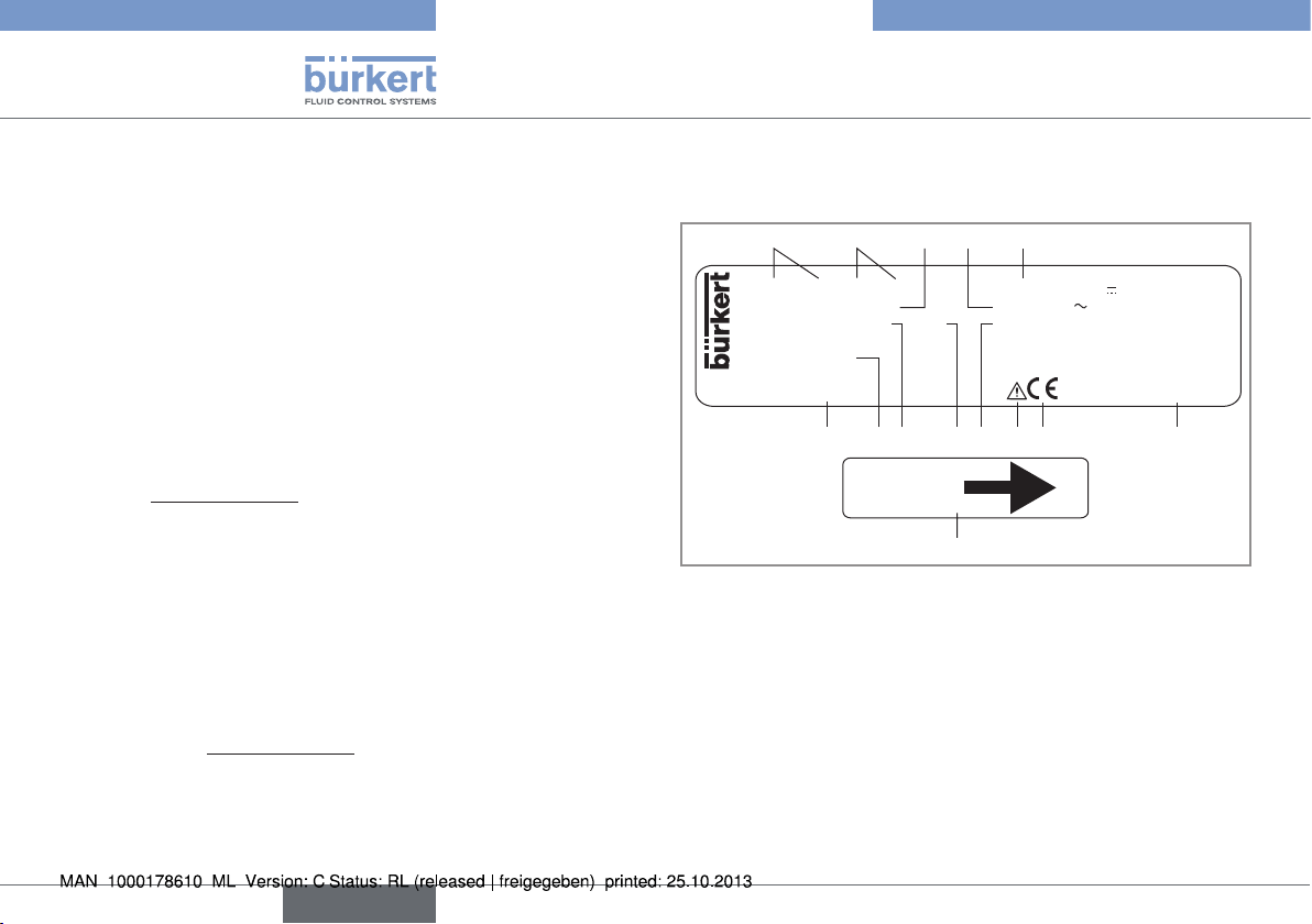
5. DESCRIPTION OF THE NAME
PLATE
FLOW 8045 SST LONG SUPPLY: 18-36V 300 mA
DO1: 5-36V= 100mA DO2/3:250V 3A Max
DI1: 18-36V= 10mA IP65 Fluid: PN16:-15/110°C
S/N 11 162
Made in France
00449673 W43M
13
10
67891112
FLOW
14
6
English
Type 8045
Technical data
1. Measured value and type of the device
2. Specification of the flow sensor
3. Specification of the DO1 digital output
4. Specifications of the relay outputs DO2 and DO3
5. Electrical power supply and current consumption
6. Manufacturing code
7. Conformity logo
8. Warning: Before using the device, take into account the tech-
nical specifications described in these operating instructions.
9. Fluid temperature range and fluid nominal pressure
10. Protection class of the device
11. Specification of the DI1 digital input
12. Serial number
13. Order code
14. Shows the flow direction
Fig. 1: Name plate of the 8045 flowmeter
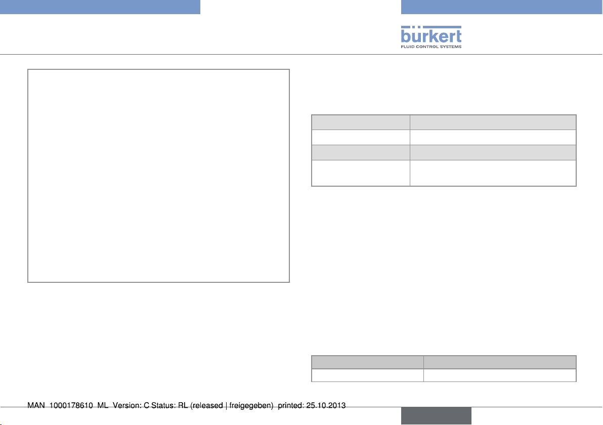
6. TECHNICAL DATA
6.1. Conditions of use
Ambient temperature -10 to +60 °C
Air humidity < 85%, non condensated
Height above see level max. 2000 m
Protection class acc.
to EN 60529
6.2. Conformity to standards and
directives
The device conforms to the EC directives through the following
standards:
• EMC: EN 61000-6-2, EN 61000-6-3
• LVD: EN 61 010-1
• Vibration: EN 60068-2-6
• Shock: EN 60068-2-27
Pressure: article 3§3 of the Pressure Directive 97/23/CE. Acc. to
the Pressure Directive 97/23/CE: the device can only be used in the
following cases (depending on the max. pressure, the DN of the pipe
and the fluid)
Type of fluid Conditions
Fluid group 1, par. 1.3.a Forbidden
IP65, device wired and cable glands
tightened and cover lid screwed tight.
English
7
Type 8045
Technical data
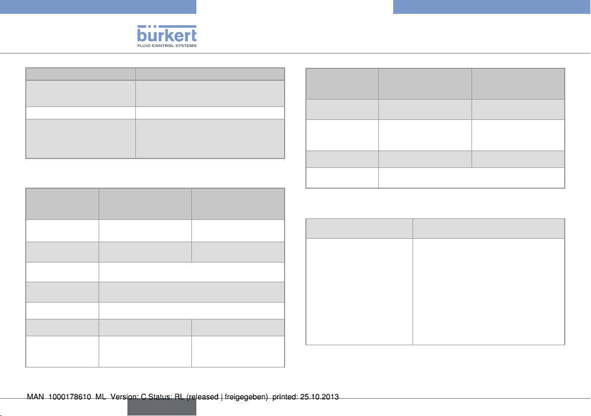
Type of fluid Conditions
Fluid group 2 par. 1.3.a
Fluid group 1 par. 1.3.b PNxDN ≤ 2000
Fluid group 2 par. 1.3.b
DN ≤ 32
or DN > 32 and PNxDN ≤ 1000
DN ≤ 200
or PN ≤ 10
or PNxDN ≤ 5000
6.3. Mechanical data
Part
Housing / seal PC / NBR Black PPA / NBR
Cover with lid /
seal
Front foil Polyester
M20x1,5 cable
glands / seal
Screws Stainless steel
Nut PC PPA
Flow sensor
(exposed to the
fluid)
Material (8045 with
flow sensor in PVDF)
PC / silicone PSU / silicone
PA / neoprene
PVDF Stainless steel 316L
Material (8045
with flow sensor in
stainless steel)
(DIN 1.4404)
Part
Seal FKM 8045 with a G2" nut:
Earth ring of the
flow sensor
Electrodes holder - PEEK
Electrodes Stainless steel 316L (DIN 1.4404) or Alloy
Material (8045 with
flow sensor in PVDF)
Stainless steel 316L
(DIN 1.4404) or Alloy
C22
Material (8045
with flow sensor in
stainless steel)
FKM
-
C22
6.4. General data
Min. fluid conductivity 20 µS/cm
Fluid temperature
• 8045 with flow sensor
in PVDF
• 8045 with flow sensor in
stainless steel
The fluid temperature may be
restricted by the fluid pressure, the
material the flow sensor is made of
and the material the S020 fitting used
is made of.
• 0 to +80 °C
• -15 to +110 °C
8
English
Type 8045
A
A
Technical data
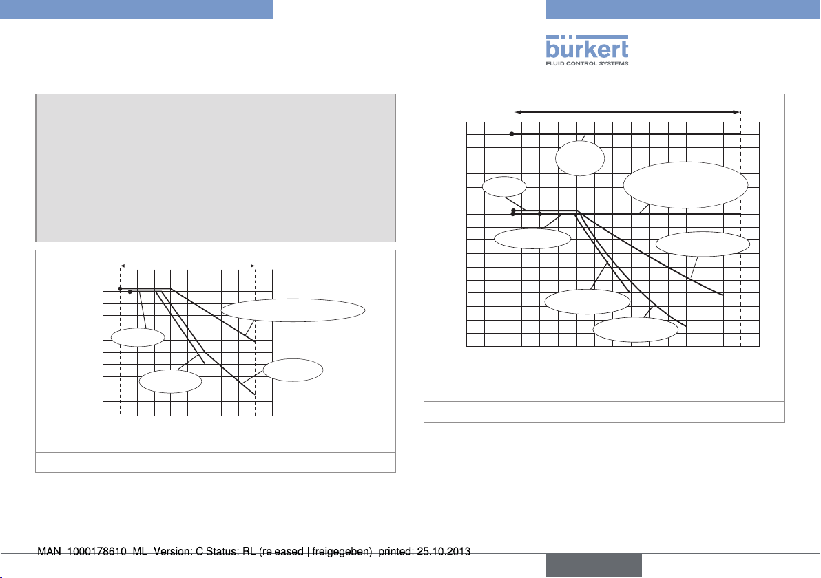
Fluid pressure
The fluid pressure may be restricted
by the fluid temperature, the material
the flow sensor is made of, the
material the S020 fitting used is made
of and the DN of the fitting used.
• 8045 with flow sensor
• PN10
in PVDF
• 8045 with flow sensor in
• PN16
stainless steel
P (bar)
10
9
8
7
PVC + PP
6
5
4
3
2
1
0
PVC (PN10)
0 +20 +40 +60 +80
PVDF (PN10) /
PP (PN10)
T (°C)
Metal
A: range of use
Fig. 2: Fluid pressure /temperature dependency for a 8045 with
PVDF flow sensor and a fitting S020 in metal, PVC, PVDF
or PP
P (bar)
16
15
14
13
12
11
PVDF
Metal
(PN16)
1)
DN100 for measuring
devices with a clamp con-
nection (PN10)
10
9
8
7
PVC + PP
PVDF (PN10)
6
5
4
3
2
1
0
-20 0 +20 +40 +60 +80 +100 +120
PVC (PN10)
PP (PN10)
T (°C)
1)
Except DN100 for measuring devices with a clamp connection
A: range of use
Fig. 3: Fluid pressure /temperature dependency for a 8045 with
stainless steel flow sensor and a fitting S020 in metal,
PVC, PVDF or PP
English
9
Type 8045
Technical data
6.5. Electrical data
Power supply • 18-36 V DC, filtered and
regulated
• oscillation rate: ±5 %
Current consumption 300 mA max. (at 18 V DC)
Transistor output DO1
• type
• function
• frequency
• Electrical data
• duty cycle if f > 2 Hz
• min. pulse duration if
f < 2 Hz
• protections
• NPN / PNP (wiring dependent),
open collector
• pulse output (by default), user
configurable
• 0-250 Hz
• 5-36 V DC, 100 mA max.
• 1/2
• 250 ms
• galvanically isolated, and
protected against overvoltages, polarity reversals and
short-circuits
Relay outputs (DO2 and
DO3)
• operating
• electrical data of the load
• max. breaking capacity
• life span
Current output AO1
• specification
• max. loop impedance
Digital input (DI1)
• supply voltage
• input impedance
• min. pulse duration
• protections
• hysteresis (by default), configurable, normally open
• 250 V AC / 3 A or 30 V DC /
3 A (resistive load)
• 750 VA (resistive load)
• min. 100000 cycles
• 4-20 mA, sink or source (wiring
dependent), 22 mA to indicate
a fault
• 1300 W at 36 V DC, 1000 W at
30 V DC, 700 W at 24 V DC,
450 W at 18 V DC
• 18-36 V DC
• 15 kW
• 200 ms
• galvanically isolated, and protected against polarity reversals
and voltage spikes
10
English
Type 8045
Installation and wiring
6.6. Electrical connection
Type of connection Through two M20x1,5 cable
glands
Cable specifications
• cable type
• Cross section
• Diameter of each cable:
- if only one cable is used
per cable gland
- if two cables are used per
cable gland
• shielded
• 0,5 to 1,5 mm
- 6...12 mm
- 4 mm, with the supplied
multi-way seal
2
7. INSTALLATION AND WIRING
7.1. Safety instructions
danger
Risk of injury due to high pressure in the installation.
Risk of injury due to electrical voltage.
Risk of injury due to high fluid temperatures.
Risk of injury due to the nature of the fluid.
Warning
Risk of injury due to non-conforming installation.
• The electrical and fluid installation can only be carried out by
qualified and skilled staff with the appropriate tools.
• Install appropriate safety systems (correctly rated fuse and/or
circuit-breaker);
• Respect standard NF C 15-100 / IEC 60364.
• Respect the assembly instructions for the fitting used.
Risk of injury due to unintentional switch on of power supply
or uncontrolled restarting of the installation.
• Take appropriate measures to avoid unintentional activation of
the installation.
• Guarantee a set or controlled restarting of the process subsequent to any intervention on the device.
English
11
Protect this device against electromagnetic interference,
ultraviolet rays and, when installed outdoors, the effects of
the climatic conditions.
7.2. Recommandations for installing
the 8045 on the pipe
→ Choose an S020 fitting appropriate to the velocity of the fluid
inside the pipe.
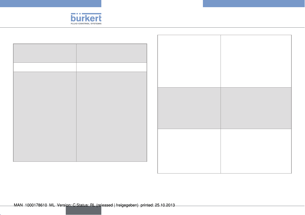
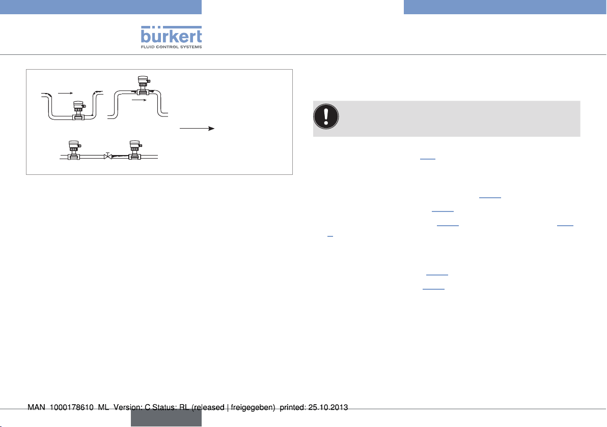
→ Install the device on the pipe in such a way that the upstream
and downstream distances are respected according to the
design of the pipes, refer to standard EN ISO 5167-1 and Fig.
4 :
Type 8045
Installation and wiring
flow direction
50 x DN 5 x DN
With control valve Pipe with 2 elbows at 90° in 3
40 x DN 5 x DN
dimensions
25 x DN 5 x DN 20 x DN 5 x DN
Pipe with 2 elbows at 90° Pipe with 1 elbow at 90° or 1
T-piece
12
18 x DN 5 x DN 15 x DN 5 x DN
With pipe expansion With pipe reduction
Fig. 4: Upstream and downstream distances depending on the
design of the pipes.
English
Type 8045
Installation and wiring
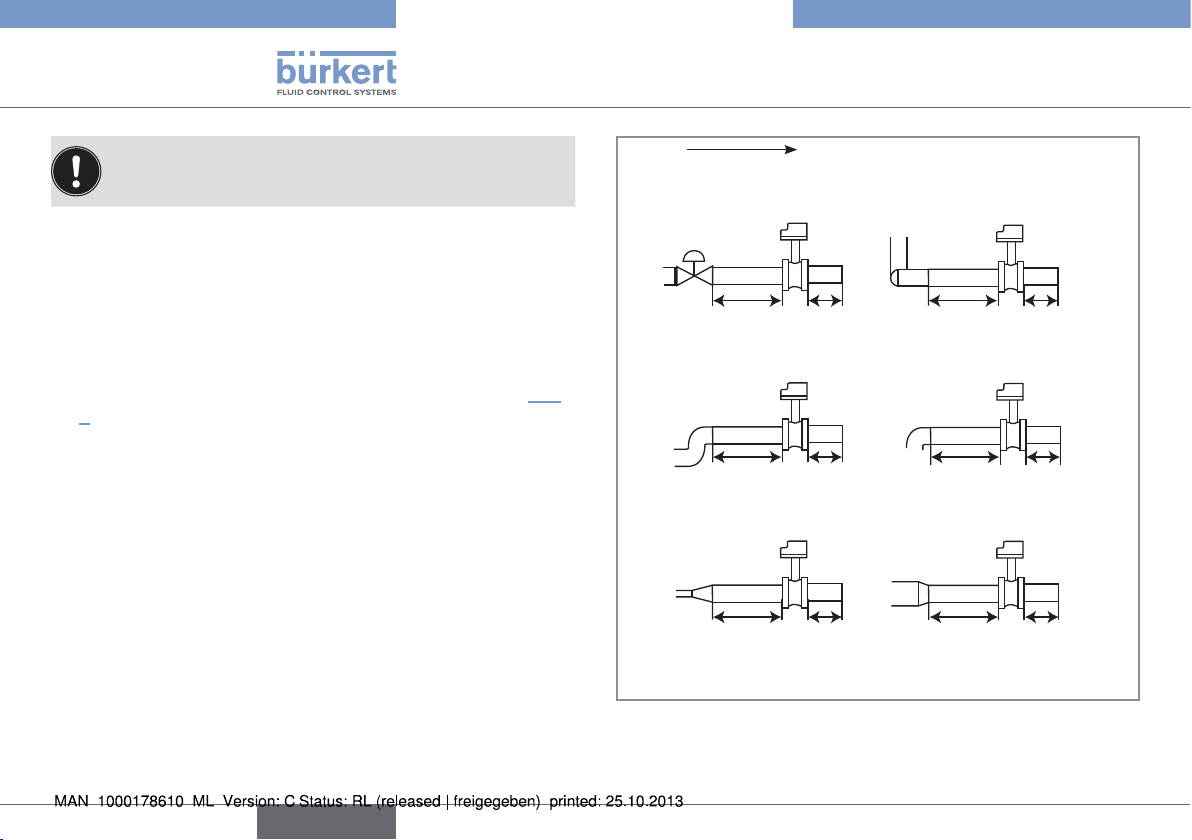
→ Respect the following additional mounting conditions to ensure
that the measuring device operates correctly:
- Preferably install the device at a 45° angle to the horizontal centre of
the pipe to avoid having deposits on the electrodes and false measurements due to air bubbles (see Fig. 5);
45°
45°
Fig. 5: Mounting angle on the pipe
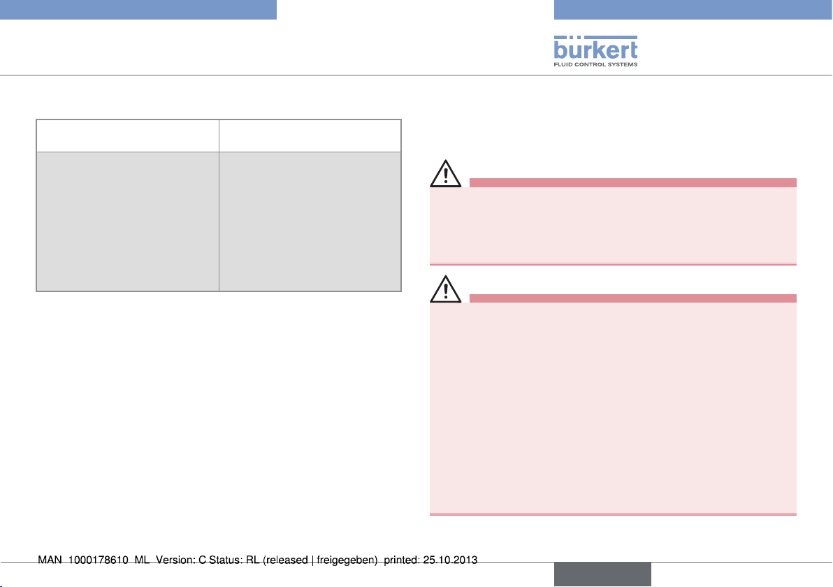
- Ensure that the pipe is always filled in the section around the
device (see Fig. 6).
- When mounting vertically ensure that the flow direction is in an
upward direction (see Fig. 6).
Horizontal mounting
Correct Incorrect
Vertical mounting
flow direction
Correct Incorrect
Fig. 6: Filling of the pipe
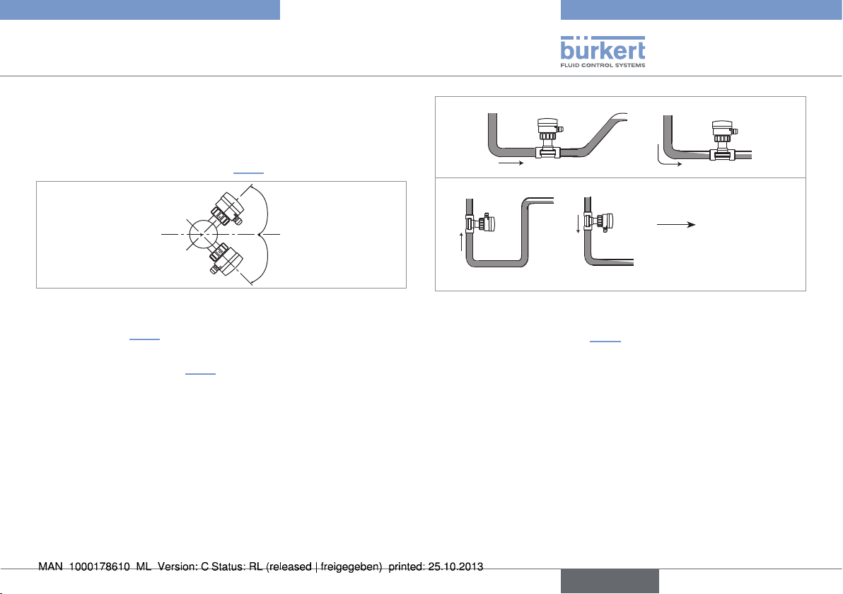
- Prevent the formation of air bubbles in the pipe in the section
around the device (see Fig. 7).
- Always mount the device upstream a possible injection point
in the pipe of a high-conductivity fluid (for example: acid, base,
saline,...).
English
13
Correct
Correct Incorrect
Fig. 7: Air bubbles within the pipe
Incorrect
flow direction
→ If necessary, use a flow conditioner to improve measurement
precision.
Type 8045
Installation and wiring
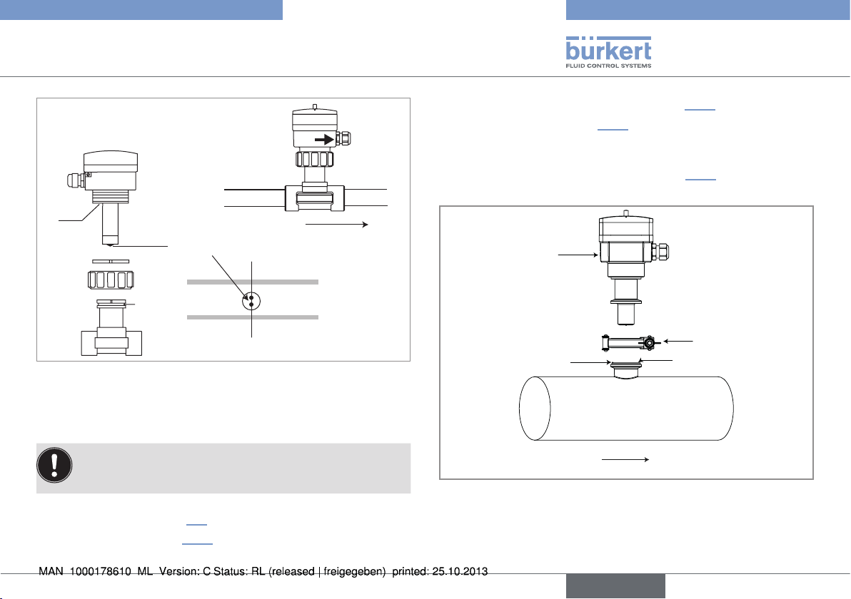
7.3. Installation into the pipe of a
8045 with a G2'' nut
In order to ensure a high accuracy of the measurements and
good stability of the „flow zero“ point, install the device into
the processed medium at least 24 H before calibration.
→ Install the S020 fitting into the pipe taking into account the rec-
ommendations in chap. 7.2.
→ Check that there is a seal on the fitting and that it is not damaged.
Replace the seal if necessary.
→ Check that there is a seal (see mark 6, Fig. 8) on the flow sensor.
→ Insert the nut (see mark 3, Fig. 8) on the fitting.
→ Insert the snap ring (mark 2 Fig. 8) into the groove (mark 5 Fig.
8).
→ Position the arrow on the side of the device in the direction of the
flow: the totalizers will increment.
→ Insert the device (mark 1 Fig. 8) into the fitting.
→ Tighten the nut (mark 3, Fig. 8) by hand on the device.
14
English
Type 8045
Installation and wiring
1
FLOW
→ Make sure that the polarizing pin (mark 4 Fig. 9) is on the fitting.
→ Insert the device (mark 1 Fig. 9) into the fitting. Position the
arrow on the side of the device in the direction of the flow: the
totalizers will increment.
→ Tighten by hand the clamp collar (mark 2 Fig. 9).
→ Charge the pipe to make sure the installation is tight.
6
Electrodes
2
3
5
4
flow direction
Fig. 8: Installation into the pipe of a 8045 with a G2'' nut
7.4. Installation into the pipe of a
8045 with a clamp connection
In order to ensure a high accuracy of the measurements and
good stability of the „flow zero“ point, install the device into
the processed medium at least 24 H before calibration.
→ Install the S020 fitting into the pipe taking into account the rec-
ommendations in chap. 7.2.
→ Install the seal (mark 3 Fig. 9) on the S020 fitting.
1
2
4
flow direction
3
Fig. 9: Installation into the pipe of a 8045 with a clamp
connection
English
15
Type 8045
Installation and wiring
7.5. Wiring
danger
Risk of injury due to electrical voltage.
• Shut down the electrical power source of all the conductors and
isolate it before carrying out work on the system.
• Observe all applicable accident protection and safety regulations for electrical equipment.
• Use a high quality electrical power supply (filtered and
regulated).
• Make sure the installation is equipotential. See chap.
7.5.1.
• Use shielded cables with a temperature limit of 80 °C
minimum.
• Do not install the cables near high voltage or high frequency cables; If this cannot be avoided, observe a min.
distance of 30 cm.
• Protect the power supply by means of a 300 mA fuse and
a switch.
• Protect the relays by means of a max. 3 A fuse and a
circuit breaker (depending on the process).
• Do not apply both a dangerous voltage and a safety extralow voltage to the relays.
Insert the supplied stopper gasket into the unused cable
gland to ensure the tightness of the device.
If two cables are used in the same cable gland, first insert
the supplied multi-way seal.
To wire the device:
→ Loosen the screw from the lid.
→ Flip the lid.
→ Loosen the 4 screws from the cover of the housing.
→ Remove the cover.
→ Loosen the nuts of the cable glands.
→ Insert the cable through the nut then through the cable gland.
→ Make sure the earth cable coming from the housing and, on a
version with stainless steel sensor, the cable coming from the
flow sensor, are connected as shown in Fig. 15, chap. 7.5.2.
→ Wire acc. to chap. 7.5.1 to 7.5.3.
7.5.1. Equipotentiality of the installation
To ensure the equipotentiality of the installation (power supply device - fluid):
→ Connect together the various earth spots in the installation to
eliminate the potential differences that may occur between different earthes.
→ Observe faultless earthing of the shield of the power supply
cable, at both ends.
16
English
Type 8045
Installation and wiring
→ Connect the negative power supply terminal to the earth to sup-
press the effects of common mode currents. If this connection
cannot be made directly, a 100 nF/50 V capacitor can be fitted
between the negative power supply terminal and the earth.
→ Special attention has to be paid if the device is installed on
plastic pipes because there is no direct earthing possible.
Proper earthing is performed by earthing together the metallic
instruments such as pumps or valves, that are as close as possible to the device. If no such instrument is near the device,
insert metallic earth rings inside the plastic pipes upstream and
downstream the device and connect these parts to the same
earth. The earth rings must be in contact with the fluid.
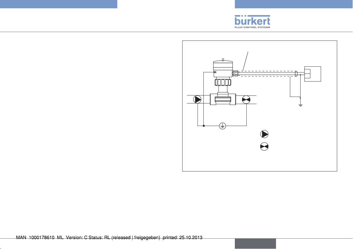
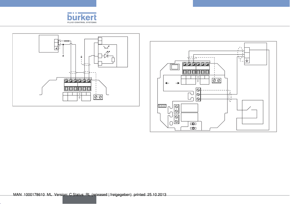
Power cable shield
Power supply
18-36VDC
+
-
1)
Pipes in plastic
Valve, pump,... (or earthing rings,
not provided, inserted into the
pipe)
1)
If a direct earth connection is not possible, fit a 100 nF / 50 V
capacitor between the negative power supply terminal and the earth.
Fig. 10: Equipotentiality skeleton diagram with pipes in plastic
English
17
Type 8045
Installation and wiring
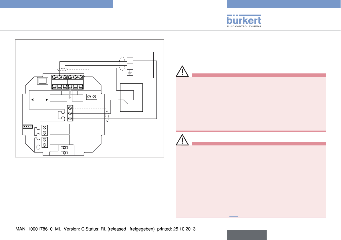
Power cable shield
Power supply
18-36VDC
+
-
1)
Metal pipe
1)
If a direct earth connection is not possible, fit a 100 nF / 50 V
capacitor between the negative power supply terminal and the
earth.
Fig. 11: Equipotentiality skeleton diagram with pipes in metal
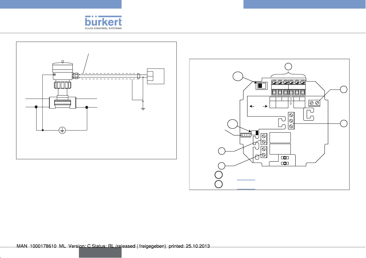
7.5.2. Terminal assignment and use of the
selectors
1
A
2
4 pin ribbon ca-
ble coming from
the flow sensor
Selector
Selector
B
4
5
A
: see Fig. 13
B
: see Fig. 14
CURRENT
OFF ON
DO3
SOURCESINK
DO2
AO1
L+ L-PEP+P-Iout
Supply
18...36 Vdc
PE
-
+
DI1
PULSE
DO1
PE
3
18
English
Type 8045
Installation and wiring
Terminal block 1
Iout: 4-20 mA output (AO1)
L+: V+ (positive voltage)
L-: 0V (power supply ground)
PE: functional earth, wired in the factory (see Fig. 15)
P+: positive transistor output (DO1)
P-: negative transistor output (DO1)
Terminal block 2
PE: shieldings of both the power supply cable and the AO1
and DO1 output cables
Terminal block 3
PE: functional earth of the DI1 digital input
-: negative signal of the DI1 input
+: positive signal of the DI1 input
Terminal block 4: wiring the DO2 relay output
Terminal block 5: wiring the DO3 relay output
Fig. 12: Terminal assignment
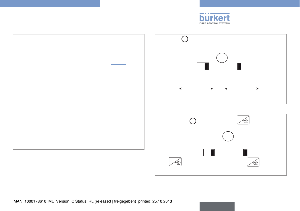
A
Use switch
to configure the wiring of the 4-20 mA cur-
rent output in sinking or sourcing mode.
A
CURRENT
SOURCESINK
Wire the current output
in sourcing mode.
Fig. 13: Sink/source switch
B
Use the switch
unauthorized access to the configuration of the device.
to lock/unlock the
CURRENT
SOURCESINK
Wire the current output in
sinking mode.
ENTER
key to prevent
B
OFF ON
ENTER
The
Fig. 14: Switch to lock/unlock the ENTER key
key is unlocked (de-
fault position).
OFF ON
ENTER
The
locked.
key is
English
19
123456
Type 8045
Installation and wiring
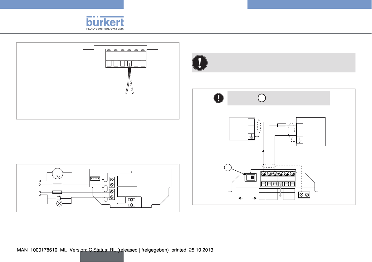
7.5.4. Wiring the AO1 current output
For safety reasons, secure the cables using a non-conducting cable clamp.
The 4-20 mA output can be wired in either sourcing or sinking
mode.
Earth cable coming from the housing.
On a version with stainless steel flow sensor, a second cable
is coming from the sensor.
Fig. 15: Connection of the earth wire coming from the housing
(made in the factory)
7.5.3. Wiring the DO2 and DO3 relay
outputs
m
230 VAC
230 VAC
Fig. 16: Wiring of the DO2 and DO3 relay outputs
20
3 A
3 A
English
DO2
DO3
Position the A switch to the right.
PULSE
DO1
(*)
Power supply
18-36 V DC
+
-
PE
4-20mA input at external
device
A
CURRENT
SOURCESINK
+
300 mA
-
I
L+ L-PEP+P-Iout
Supply
AO1
18...36 Vdc
Fig. 17: Wiring of the 4-20 mA output (AO1) in sourcing mode
*) If a direct earth connection is not possible, fit a 100 nF/50 V
capacitor between the negative power supply terminal and the earth
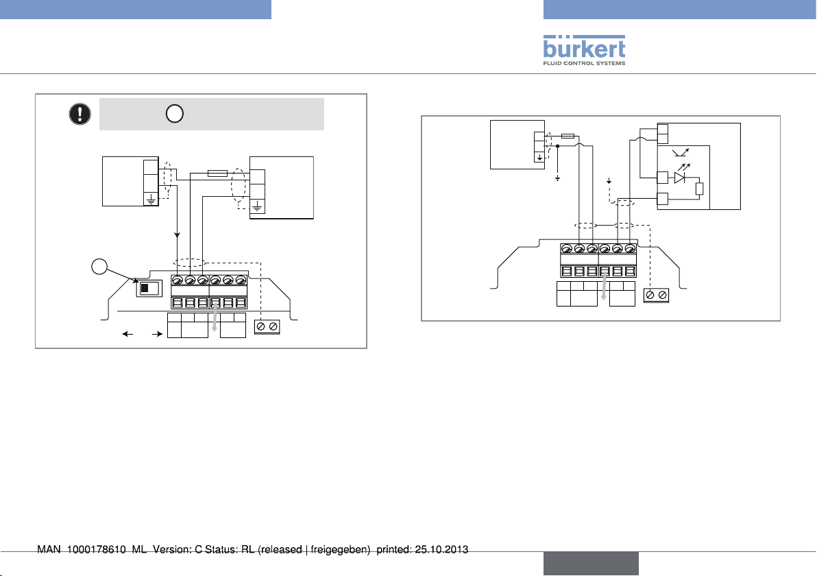
Type 8045
18-36 V DC
Installation and wiring
Position the A switch to the left.
I
AO1
L+ L-PEP+P-Iout
Supply
18...36 Vdc
300 mA
PULSE
DO1
(*)
+
-
Power supply
PE
4-20mA input at external
device
A
CURRENT
SOURCESINK
+
-
Fig. 18: Wiring of the 4-20 mA output (AO1) in sinking mode
*) If a direct earth connection is not possible, fit a 100 nF/50 V
capacitor between the negative power supply terminal and the earth
7.5.5. Wiring the DO1 transistor output
18-36 V DC
Power supply
+
-
(*)
300 mA
L+ L-PEP+P-Iout
Supply
AO1
18...36 Vdc
PULSE
DO1
Fig. 19: NPN wiring of the DO1 transistor output
*) If a direct earth connection is not possible, fit a 100 nF/50 V
capacitor between the negative power supply terminal and the earth
+
5-36 VDC
-
+
-
PE
PLC
English
21
Type 8045
Installation and wiring
18-36 V DC
Power supply
300 mA
+
-
(*)
+
5-36 VDC
-
+
-
PLC
L+ L-PEP+P-Iout
Supply
AO1
18...36 Vdc
PULSE
DO1
PE
Fig. 20: PNP wiring of the DO1 transistor output
*) If a direct earth connection is not possible, fit a 100 nF/50 V
capacitor between the negative power supply terminal and the earth
7.5.6. Wiring the DI1 digital input
(*)
CURRENT
SOURCESINK
DO3
DO2
AO1
L+ L-PEP+P-Iout
Supply
18...36 Vdc
DI1
PE
-
+
PULSE
DO1
PE
18-36 V DC
+
-
Power supply
Switch
22
English
Type 8045
Adjustment, commissioning
CURRENT
SOURCESINK
DO2
AO1
L+ L-PEP+P-Iout
Supply
18...36 Vdc
PE
-
+
DI1
PULSE
DO1
PE
Power supply
18-36 V DC
+
-
(*)
Switch
8. ADJUSTMENT, COMMISSIONING
8.1. Safety instructions
Warning
Risk of injury due to non-conforming operating.
Non-conforming operating could lead to injuries and damage the
device and its surroundings.
• The operators in charge of operating must have read and understood the contents of these operating instructions.
• In particular, observe the safety recommendations and intended use.
• The device/installation must only be operated by suitably trained
staff.
Warning
DO3
Fig. 21: Possible wirings of the DI1 digital input
*) If a direct earth connection is not possible, fit a 100 nF/50 V
capacitor between the negative power supply terminal and the earth
Danger due to non-conforming commissioning.
Nonconforming commissioning could lead to injuries and damage
the device and its surroundings.
• Before commissioning, make sure that the staff in charge
have read and fully understood the contents of the operating
instructions.
• In particular, observe the safety recommendations and intended use.
• The device / the installation must only be commissioned by suitably trained staff.
• Before commissioning the device, enter the K factor of the fitting used. See chap. 8.6.
English
23
8.2. Operating levels of the device
The device has two operating levels: the Process level and the Configuration level.
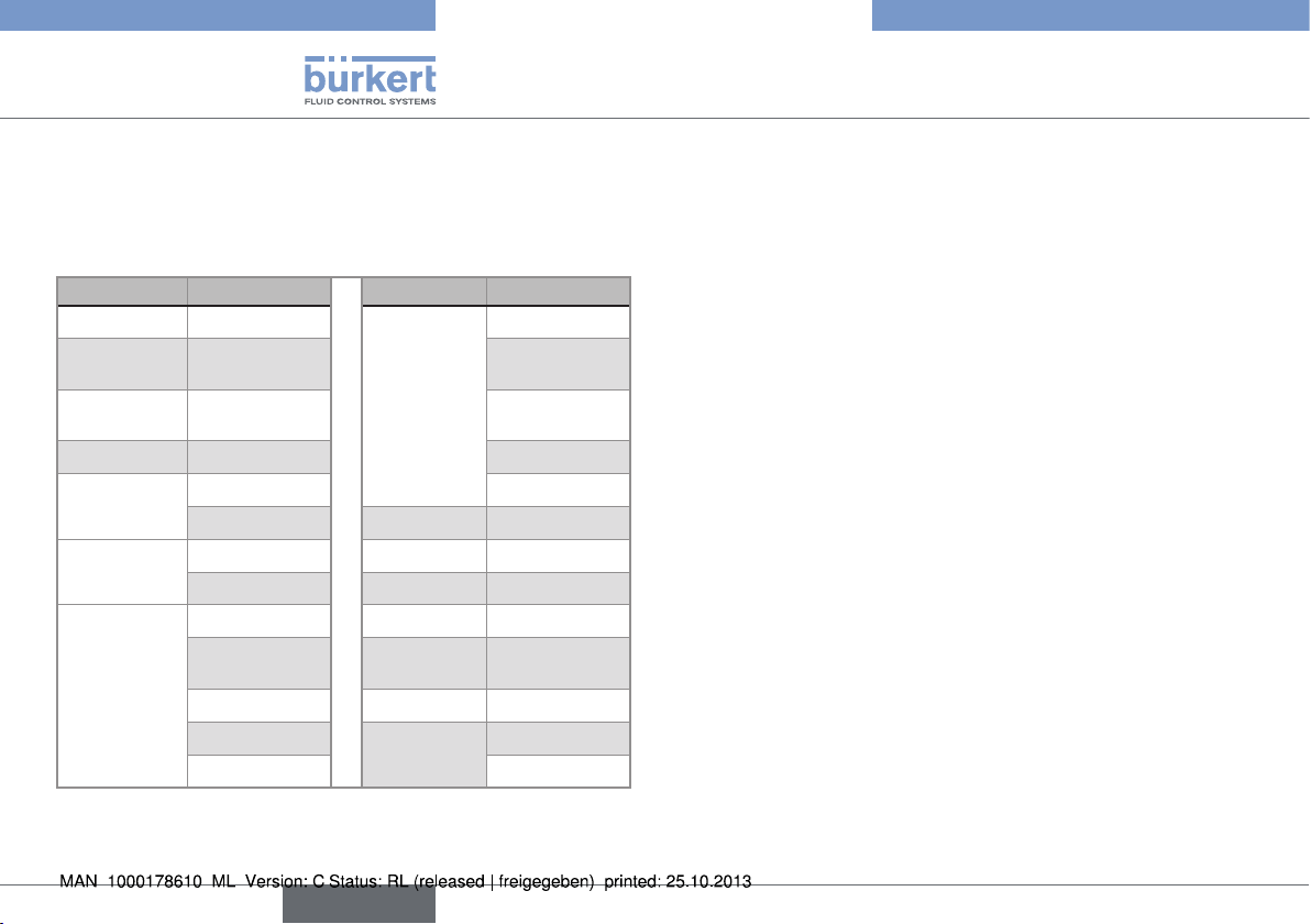
Table 1: Default settings of the device
Function Default value Function Default value
LANGUAGE English OUTPUT
UNIT of the
flow rate
UNIT of the
totalizers
K-FACTOR 1.000 Not inverted
OUTPUT
AO1
OUTPUT
DO1
OUTPUT
DO2
l/min. 3-= 0.000
litre 3+= 0.000
4mA= 0.000
20mA= 0.000 INPUT DI1 disable
pulse FILTER 5, slow
PU= 0.00 litre FREQUENC. 50Hz
Hysteresis CUT-OFF 0.000
2-= 0.000 BACKLIT level 9, acti-
2+= 0.000 K-SENSOR Kw= 1.000
Not inverted FLOW-W. W-= 0.000
time delay = 0
DO3
Hysteresis
time delay = 0
vated for 30s
W+= 0.000
Type 8045
Adjustment, commissioning
24
English
Type 8045
Adjustment, commissioning
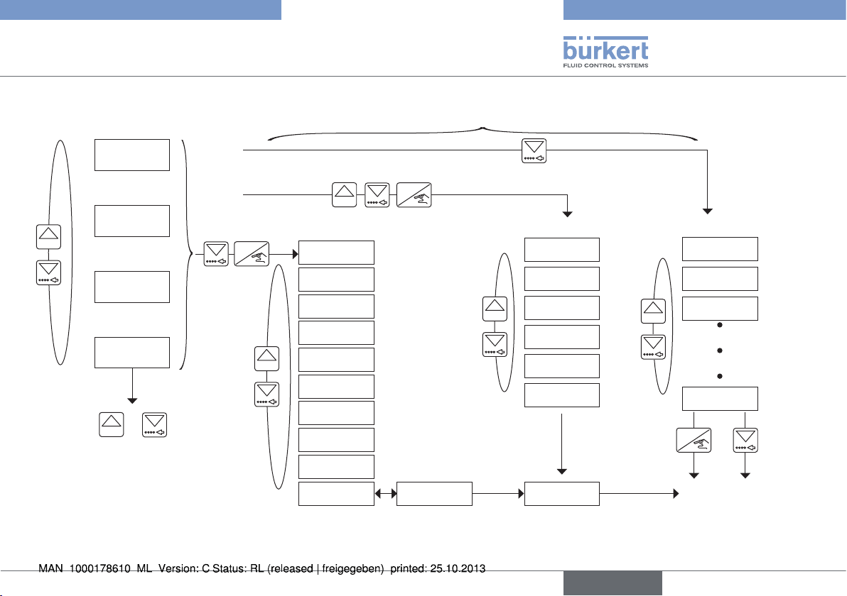
Process level
12.6 L/s
16.45 mA
0......9
Parameters menu Test Menu
ENTER
LANGUAGE
> 5 s
87654 L
UNit
K-FACtOR
OUtPUt
231 L.
0......9
iNPUt
FiLtER
+
0......9
> 2 s
To reset the daily totalizer (identified by
a dot after the volume units).
tOtAL
FREqUENC.
CUt-OFF
BACKLit
1)
Accessible when the device status LED is orange or red.
2)
If the ENTER key is unlocked.
0......9
> 5 s
Configuration level
ENTER
END
0......9
> 2 s
CAL AO1
CALiB 0
FLOw
K-sENsOR
FLOw-w.
sAVE N/Y
END
Information menu
mEAs. OVF
CAL. FAiL
NEG. FLOw
0......9
END
ENTER
or
2)
Process level
1)
English
25
Type 8045
Adjustment, commissioning
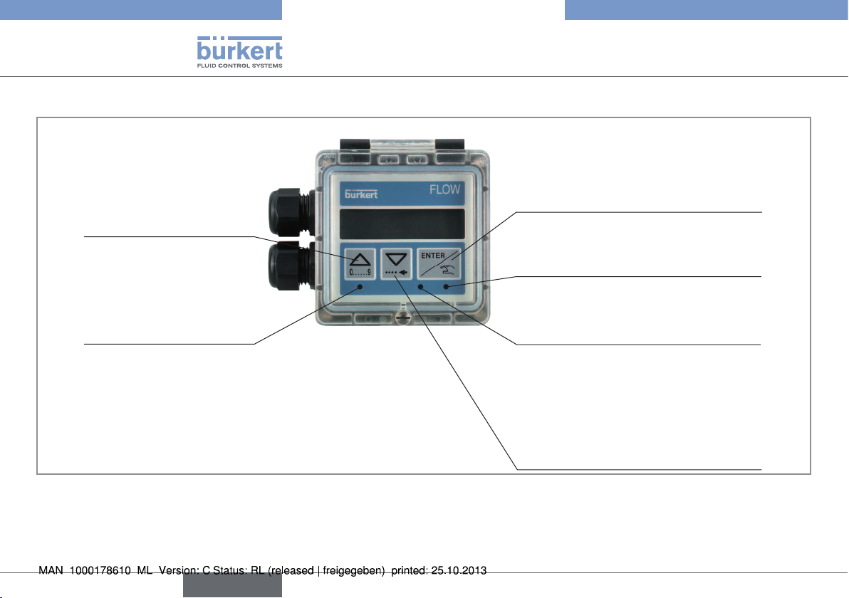
8.3. Description of the navigation keys and the state LEDs
26
• Scrolling up the
parameters
• Incrementing the figure
selected
Device state LED: see following table.
English
• Selecting the displayed parameter
• Confirming the settings
Status LED of relay DO3 (LED ON =
contact closed)
Status LED of relay DO2 (LED ON =
contact closed)
• Reading the messages
• Scrolling through the parameters
• Selecting the figure on the left
Type 8045
Adjustment, commissioning
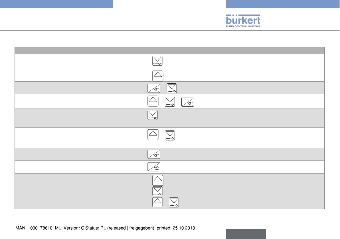
8.4. Using the navigation keys
You want to... Press...
move between parameters within a level or a menu.
access the Parameters menu.
access the Test menu.
access the Information menu.
•
•
ENTER
0......9
0......9
to go to the next parameter.
to go to the previous parameter.
+ simultaneously for 5 s, in the Process level
ENTER
+ +
simultaneously for 5 s, in the Process level
for 2 s, in the Process level, when the device status LED is orange or red.
reset the daily totalizer.
select the displayed parameter.
confirm the displayed value.
modify a numerical value.
0......9
+ simultaneously for 2 s, when the daily totalizer is displayed in the
Process level
ENTER
ENTER
to increase the blinking digit.
•
0......9
to select the digit at the left of the blinking digit.
•
0......9
+ to move the decimal point.
•
English
27
Type 8045
Adjustment, commissioning
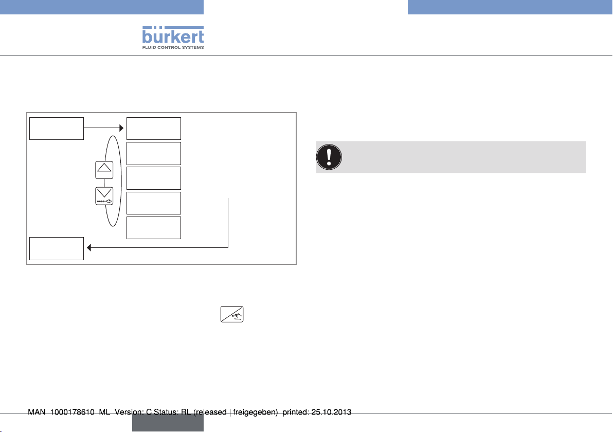
8.5. Choosing the display language
When the device is energized for the first time, the display language
is English.
LANGUAGE ENGLish
0......9
DEUtsCh
FRANçAis
→ Confirm the displayed
language: The selected
language is immediately active.
itALiANO
EsPANOL
UNit
Fig. 22: Diagram of the "LANGUAGE" parameter of the Parameters
menu
→ If you do not want to adjust another parameter, go to the "END"
parameter of the Parameters menu and press
settings or not and go back to the Process level.
ENTER
to save the
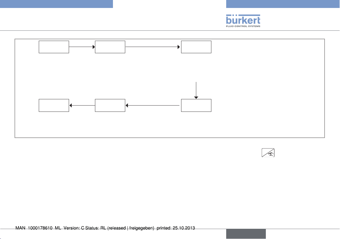
8.6. Entering the K factor of the fitting
used:
The device determines the flow rate in the pipe using the fitting K
factor.
The K factor of the fitting used can be entered here.
The device will use the new K factor as soon as "SAVE
YES" is confirmed when leaving the Parameters menu.
28
English
Type 8045
Adjustment, commissioning
K-FACtOR K=10.000
The display shows the K factor of the
fitting, may it have been entered or
determined by a teach-in procedure;
this K factor is currently used by the
device
K=2.8500
→ Enter the K factor (value between 0,0001 and
9999,9) of the fitting used.
→ Confirm the displayed value.
→ Edit the parameter.
OUtPUt VALiD N/Y
REtURN
Is only displayed if the K factor has been changed.
→ Confirm the entered K factor or not.
Fig. 23: Entering the K factor of the fitting used
→ If you do not want to adjust another parameter, go to the "END" parameter of the Parameters menu and press
not and go back to the Process level.
ENTER
to save the settings or
English
29
Type 8045
Maintenance and troubleshooting
9. MAINTENANCE AND
TROUBLESHOOTING
9.1. Safety instructions
danger
Risk of injury due to high pressure in the installation.
Risk of injury due to electrical voltage.
Risk of injury due to high fluid temperatures.
Risk of injury due to the nature of the fluid.
Warning
Risk of injury due to non-conforming maintenance.
• Maintenance must only be carried out by qualified and skilled
staff with the appropriate tools.
• Ensure that the restart of the installation is controlled after any
interventions.
→ If a problem occurs, refer to the complete operating instructions
available on the CD delivered with the device.
10. PACKAGING, TRANSPORT
note
Damage due to transport
Transport may damage an insufficiently protected device.
• Transport the device in shock-resistant packaging and away
from humidity and dirt.
• Do not expose the device to temperatures that may exceed the
admissible storage temperature range.
• Protect the electrical interfaces using protective plugs.
11. STORAGE
note
Poor storage can damage the device.
• Store the device in a dry place away from dust.
• Storage temperature of the device: -20 to +60 °C.
30
English

Type 8045
Disposal of the product
12. DISPOSAL OF THE PRODUCT
→
Dispose of the device and its packaging in an environmentallyfriendly way.
note
Damage to the environment caused by products contaminated by fluids.
• Keep to the existing provisions on the subject of waste disposal
and environmental protection.
note
Comply with the national and/or local regulations which
concern the area of waste disposal.
English
31

Type 8045
32
English

Typ 8045
Magnetisch-induktives Durchfluss-Messgerät
Quickstart
Deutsch

We reserve the right to make technical changes without notice.
Technische Änderungen vorbehalten.
Sous réserve de modifications techniques.
© Bürkert SAS, 2012 - 2013
Operating Instructions 1308/1_EU-ML 00563855 ORIGINAL_FR
1. ÜBER DEN QUICKSTART ...........................................................................3
2. BESTIMMUNGSGEMÄSSE VERWENDUNG ......................................4
3. GRUNDLEGENDE SICHERHEITSHINWEISE ....................................4
4. ALLGEMEINE HINWEISE .............................................................................6
5. BESCHREIBUNG DES TYPENSCHILDS .............................................6
6. TECHNISCHE DATEN ...................................................................................7
7. INSTALLATION UND VERKABELUNG ...............................................12
8. BEDIENUNG UND INBETRIEBNAHME ............................................. 24
9. WARTUNG, FEHLERBEHEBUNG ......................................................... 31
10. VERPACKUNG, TRANSPORT .............................................................. 31
11. LAGERUNG ...................................................................................................31
12. ENTSORGUNG DES GERÄTES .......................................................... 32

Type 8045
Warnt vor Sachschäden!
Über den Quickstart
1. ÜBER DEN QUICKSTART
Der Quickstart beschreibt den gesamten Lebenszyklus des Gerätes.
Bewahren Sie diese Anleitung so auf, dass sie für jeden Benutzer
zugänglich ist und jedem neuen Eigentümer des Gerätes wieder zur
Verfügung steht.
Wichtige Informationen zur Sicherheit!
Lesen Sie den Quickstart sorgfältig durch. Beachten Sie vor allem
die Kapitel Grundlegende Sicherheitshinweise und Bestimmungs-
gemäße Verwendung.
• Der Quickstart muss gelesen und verstanden werden.
Der Quickstart erläutert beispielhaft die Montage und Inbetriebnahme des Gerätes.
Die ausführliche Beschreibung des Gerätes finden Sie in der entsprechenden Bedienungsanleitung auf der mitgelieferten CD.
1.1. Darstellungsmittel
GefaHR!
Warnt vor einer unmittelbaren Gefahr!
• Bei Nichteinhaltung sind Tod oder schwere Verletzungen die
Folge.
waRnunG!
Warnt vor einer möglicherweise gefährlichen Situation!
• Bei Nichteinhaltung drohen schwere Verletzungen oder Tod.
VORSICHT!
Warnt vor einer möglichen Gefährdung!
• Nichtbeachtung kann mittelschwere oder leichte Verletzungen
zur Folge haben.
HInweIS!
• Bei Nichtbeachtung kann das Gerät oder die Anlage beschädigt
werden.
bezeichnet wichtige Zusatzinformationen, Tipps und
Empfehlungen.
verweist auf Informationen in dieser Bedienungsanleitung
oder in anderen Dokumentationen.
→ markiert einen Arbeitsschritt, den Sie ausführen müssen.
1.2. Begriffsdefinition "Gerät"
Der in dieser Anleitung verwendete Begriff "Gerät" steht immer für
das Durchfluss-Messgerät Typ 8045.
deutsch
3

Type 8045
Bestimmungsgemässe Verwendung
2. BESTIMMUNGSGEMÄSSE
VERWENDUNG
Bei nicht bestimmungsgemäßem Einsatz dieses Gerätes
können Gefahren für Personen, Anlagen in der Umgebung
und die Umwelt entstehen.
• Das Durchfluss-Messgerät 8045 ist ausschließlich für die
Durchflussmessung in Flüssigkeiten bestimmt.
• Schützen Sie das Gerät vor elektromagnetischen Störungen, U.V.-Bestrahlung und bei Außenanwendung vor
Witterungseinflüssen.
• Für den Einsatz sind die in den Vertragsdokumenten und der
Bedienungsanleitung spezifizierten zulässigen Daten, Betriebsund Einsatzbedingungen zu beachten.
• Zum sicheren und problemlosen Einsatz des Gerätes müssen
Transport, Lagerung und Installation ordnungsgemäß erfolgen,
außerdem müssen Betrieb und Wartung sorgfältig durchgeführt
werden.
• Achten Sie immer darauf, dieses Gerät auf ordnungsgemäße
Weise zu verwenden.
→ Beachten Sie bei der Ausfuhr des Gerätes gegebenenfalls
bestehende Beschränkungen.
3. GRUNDLEGENDE
SICHERHEITSHINWEISE
Diese Sicherheitshinweise berücksichtigen keine
• Zufälligkeiten und Ereignisse, die bei Montage, Betrieb und
Wartung der Geräte auftreten können.
• Ortsbezogenen Sicherheitsbestimmungen, für deren Einhaltung, auch
in Bezug auf das Installations- und Wartungspersonal, der Betreiber
verantwortlich ist.
Gefahr durch hohen Druck in der Anlage!
• Vor dem Lösen der Prozessanschlüsse die Anlage druckfrei
schalten und die Flüssigkeitszirkulation stoppen.
Gefahr durch elektrische Spannung!
• Schalten Sie vor Beginn der Arbeiten in jedem Fall alle existierenden am Gerät angeschlossenen Spannungs-Versorgungen ab,
und sichern Sie diese vor unbeabsichtigtem Wiedereinschalten!
• Beachten Sie geltende Unfallverhütungs- und Sicherheitsbestimmungen für elektrische Geräte!
Gefahr durch hohe Flüssigkeitstemperaturen!
• Das Gerät nur mit Schutzhandschuhen anfassen.
• Vor dem Lösen der Prozessanschlüsse die Flüssigkeitszirkulation stoppen und die Rohrleitung leeren.
Gefahr aufgrund der Art der Flüssigkeit!
• Beachten Sie die Regeln, die auf dem Gebiet der Unfallverhütung
und der Sicherheit in Kraft sind und die sich auf die Verwendung
gefährlicher Flüssigkeiten beziehen.
4
deutsch

Type 8045
Grundlegende Sicherheitshinweise
Allgemeine Gefahrensituationen.
Zum Schutz vor Verletzungen ist zu beachten
• Dieses Gerät nicht für die Durchflussmessung von Gas
einsetzen.
• Dieses Gerät nicht in explosionsgefährdeten Bereichen
einsetzen.
• Dieses Gerät nicht in einer Umgebung verwenden, die mit den
Werkstoffen, aus denen es besteht, inkompatibel ist.
• Belasten Sie das Gerät nicht mechanisch (z. B. durch Ablage
von Gegenständen oder als Trittstufe).
• Nehmen Sie keine äußerlichen oder innerlichen Veränderungen
am Gerät vor.
• Dass die Anlage nicht unbeabsichtigt betätigt werden kann.
• Installations- und Instandhaltungsarbeiten dürfen nur von autorisiertem Fachpersonal mit geeignetem Werkzeug ausgeführt
werden.
• Nach einer Unterbrechung der elektrischen Versorgung ist ein
definierter oder kontrollierter Wiederanlauf des Prozesses zu
gewährleisten.
• Betreiben Sie das Gerät nur in einwandfreiem Zustand und
unter Beachtung der Bedienungsanleitung.
• Bei der Einsatzplanung und dem Betrieb des Gerätes die allgemeinen Regeln der Technik einhalten.
HInweIS!
Das Gerät kann durch das Medium beschädigt werden.
• Kontrollieren Sie systematisch die chemische Verträglichkeit der
Werkstoffe, aus denen das Gerät besteht, und der Flüssigkeiten, die mit diesem in Berührung kommen können (zum Beispiel:
Alkohole, starke oder konzentrierte Säuren, Aldehyde, Basen,
Ester, aliphatische Verbindungen, Ketone, aromatische oder
halogenierte Kohlenwasserstoffe, Oxidations- und chlorhaltige
Mittel).
HInweIS!
Elektrostatisch gefährdete Bauelemente / Baugruppen!
• Das Gerät enthält elektronische Bauelemente, die gegen
elektrostatische Entladung empfindlich reagieren. Berührung
mit elektrostatisch aufgeladenen Personen oder Gegenständen
gefährdet diese Bauelemente. Im schlimmsten Fall werden sie
sofort zerstört oder fallen nach der Inbetriebnahme aus.
• Beachten Sie die Anforderungen nach EN 61340 -5-1 und 5-2,
um die Möglichkeit eines Schadens durch schlagartige elektrostatische Entladung zu minimieren bzw. zu vermeiden!
• Achten Sie ebenso darauf, dass Sie elektronische Bauelemente
nicht bei anliegender Versorgungsspannung berühren!
deutsch
5

Type 8045
1
2 5
3 4
Allgemeine Hinweise
4. ALLGEMEINE HINWEISE
4.1. Herstelleradresse und
internationale Kontaktadressen
Sie können mit dem Hersteller des Gerätes unter folgender Adresse
Kontakt aufnehmen:
Bürkert SAS
Rue du Giessen
BP 21
F-67220 TRIEMBACH-AU-VAL
oder wenden Sie sich an Ihr lokal zuständiges Vertriebsbüro von
Bürkert.
Die internationalen Kontaktadressen finden Sie im Internet unter:
www.burkert.com
4.2. Gewährleistung
Voraussetzung für die Gewährleistung ist der bestimmungsgemäße
Gebrauch des Gerätes unter Beachtung der in der vorliegenden
Bedienungsanleitung spezifizierten Einsatzbedingungen.
4.3. Informationen im Internet
Bedienungsanleitungen und Datenblätter zum Typ 8045 finden Sie
im Internet unter: www.buerkert.de
5. BESCHREIBUNG DES
TYPENSCHILDS
FLOW 8045 SST LONG SUPPLY: 18-36V 300 mA
DO1: 5-36V= 100mA DO2/3:250V 3A Max
DI1: 18-36V= 10mA IP65 Fluid: PN16:-15/110°C
S/N 11 162
Made in France
00449673 W43M
13
10
FLOW
14
67891112
6
deutsch

Type 8045
Technische Daten
1. Messgröße und Typ des Gerätes
2. Durchfluss-Sensor-Daten
3. DO1-Digitalausgangsdaten
4. DO2- und DO3-Relaisausgangsdaten
5. Betriebsspannung und Stromverbrauch
6. Herstellungscode
7. Konformitäts-Logo
8. Warnung: Bevor das Gerät benutzt wird, die in der
Bedienungsanleitung beschriebenen technischen Daten
berücksichtigen.
9. Flüssigkeits-Druck und -Temperaturbereich
10. Schutzart des Gerätes
11. Daten des DI1-Digitaleingangs
12. Seriennummer
13. Bestellnummer
14. Zeigt die Fließrichtung an
Bild 1: Typenschild des Durchfluss-Messgerätes 8045 (Beispiel)
6. TECHNISCHE DATEN
6.1. Betriebsbedingungen
Umgebungstemperatur -10 bis +60 °C
Luftfeuchtigkeit < 85 %, nicht kondensierend
Höhe über
Meeresspiegel
Schutzart nach
EN 60529
6.2. Einhaltung von Normen und
Richtlinien
Durch folgende Normen wird die Konformität mit den EG-Richtlinien
erfüllt:
• EMV: EN 61000-6-2, EN 61000-6-3
• Niederspannungsrichtlinie: EN 61 010-1
• Vibration: EN 60068-2-6
• Schock: EN 60068-2-27
• Druck: Gemäß Artikel 3§3 der 97/23/CE Druckgeräterichtlinie.
Gemäß der 97/23/CE Druckgeräterichtlinie: Das Gerät kann nur
unter folgenden Bedingungen eingesetzt werden (abhängig vom
maximalen Druck, vom DN der Rohrleitung und von der Flüssigkeit)
max. 2000 m
IP65, mit angeschlossenem Gerät und
festgeschraubten Kabelverschraubungen und bis zum Anschlag festgeschraubtem Deckel mit Klappe.
deutsch
7

Type 8045
Technische Daten
Art der Flüssigkeit Voraussetzungen
Flüssigkeitsgruppe 1
Kap. 1.3.a
Flüssigkeitsgruppe 2
Kap. 1.3.a
Flüssigkeitsgruppe 1
Kap. 1.3.b
Flüssigkeitsgruppe 2
Kap. 1.3.b
verboten
DN ≤ 32
oder DN > 32 und PNxDN ≤ 1000
PNxDN ≤ 2000
DN ≤ 200
oder PN ≤ 10
oder PNxDN ≤ 5000
6.3. Mechanische Daten
Werkstoff (8045 mit
Teil
Gehäuse /
Dichtung
Deckel mit
Klappe /
Dichtung
Frontfolie Polyester
M20x1,5-Kabelverschraubungen
/ Dichtung
Schrauben Edelstahl
Durchfluss-Sensor
aus PVDF)
PC / NBR PPA, schwarz / NBR
PC / Silikon PSU / Silikon
Werkstoff (8045 mit
Durchfluss-Sensor
aus Edelstahl)
PA / Neopren
Werkstoff (8045 mit
Teil
Überwurfmutter PC PPA
DurchflussSensor (in
Kontakt mit der
Flüssigkeit)
Dichtung FKM 8045 mit G2"-Über-
Erdungsring
des DurchflussSensors
ElektrodenArmatur
Elektroden Edelstahl 316L (DIN 1.4404) oder Alloy C22
Durchfluss-Sensor
aus PVDF)
PVDF Edelstahl 316L (DIN
Edelstahl 316L (DIN
1.4404) oder Alloy
C22
- PEEK
Werkstoff (8045 mit
Durchfluss-Sensor
aus Edelstahl)
1.4404)
wurfmutter: FKM
-
8
deutsch

Type 8045
A
Technische Daten
6.4. Allgemeine Daten
Minimale Leitfähigkeit der
Flüssigkeit
Flüssigkeitstemperatur
• 8045 mit DurchflussSensor aus PVDF
• 8045 mit DurchflussSensor aus Edelstahl
Flüssigkeitsdruck
• 8045 mit DurchflussSensor aus PVDF
• 8045 mit DurchflussSensor aus Edelstahl
20 µS/cm
Die Flüssigkeitstemperatur kann durch
den Druck der Flüssigkeit, den Werkstoff des Durchfluss-Sensors und den
Werkstoff des verwendeten Fittings
S020 eingeschränkt sein.
• 0 bis +80 °C
• -15 bis +110 °C
Der Flüssigkeitsdruck kann durch die
Temperatur der Flüssigkeit, den Werkstoff des Durchfluss-Sensors und den
Werkstoff und DN des verwendeten
Fittings S020 eingeschränkt sein.
• PN10
• PN16
P (bar)
10
9
8
7
PVC + PP
6
5
4
3
2
1
0
PVC (PN10)
0 +20 +40 +60 +80
PVDF (PN10) /
Metall
PP (PN10)
T (°C)
A: Verwendungsbereich
Bild 2: Flüssigkeits-Druck-Temperatur-Abhängigkeit eines 8045
mit Durchfluss-Sensor aus PVDF und Fitting S020 aus
Metall, PVC, PVDF oder PP
deutsch
9

P (bar)
A
16
15
14
13
12
11
10
PVDF
Metall
(PN16)
1)
DN100
für Messgeräte mit
Clamp-Anschluss
(PN10)
9
8
7
PVC + PP
PVDF (PN10)
6
5
4
3
2
1
0
-20 0 +20 +40 +60 +80 +100 +120
PVC (PN10)
PP (PN10)
T (°C)
1)
Außer DN100 für Messgeräte mit Clamp-Anschluss
A: Verwendungsbereich
Bild 3: Flüssigkeits-Druck-Temperatur-Abhängigkeit eines 8045
mit Durchfluss-Sensor aus Edelstahl und Fitting S020 aus
Metall, PVC, PVDF oder PP
Type 8045
Technische Daten
6.5. Elektrische Daten
Betriebsspannung • 18-36 VDC, gefiltert und
geregelt
• Toleranz: ±5 %
Eigenstromverbrauch 300 mA max. (bei 18 V DC)
Transistor-Ausgang DO1
• Ty p
• Funktion
• Frequenz
• Elektrische Daten
• Taktverhältnis bei f > 2 Hz
• Puls-Mindestdauer bei
f < 2 z
• Schutz
• NPN / PNP (je nach Verkabelung), offener Kollektor
• Pulsausgang (Grundeinstellung), einstellbar
• 0-250 Hz
• 5-36 V DC, max. 100 mA
• 1/2
• 250 ms
• galvanisch getrennt; Schutz
gegen Überspannung, Verpolung und Kurzschluss
10
deutsch

Type 8045
Technische Daten
Relais-Ausgänge DO2 und
DO3
• Umschaltbetrieb
• Elektrische Daten der Last
• max. Schaltvermögen
• Lebensdauer
Stromausgang AO1
• Daten
• Schleifenimpedanz max.
Digital-Eingang (DI1)
• Betriebsspannung
• Eingangsimpedanz
• Puls-Mindestdauer
• Schutz
• Hysterese (Grundeinstellung),
einstellbar, stromlos geöffnet
• 250 V AC / 3 A oder 30 V DC /
3 A (ohmsche Last)
• 750 VA (ohmsche Last)
• min. 100000 Zyklen
• 4-20 mA, Senke oder Quelle (je
nach Verkabelung), 22 mA zur
Fehlermeldung
• 1300 W bei 36 V DC, 1000 W
bei 30 V DC, 700 W bei
24 V DC, 450 W bei 18 V DC
• 18-36 V DC
• 15 kW
• 200 ms
• galvanisch getrennt; Schutz
gegen Verpolung und
Spannungsspitzen
6.6. Elektrischer Anschluss
Anschluss-Typ Über zwei
M20x1,5-Kabelverschraubungen
Kabel-Daten
• Kabeltyp
• Querschnitt
• Durchmesser des Kabels:
- bei Verwendung
eines Kabels pro
Kabelverschraubung
- bei Verwendung
zweier Kabel pro
Kabelverschraubung
• abgeschirmt
• 0,5 bis 1,5 mm
- 6...12 mm
- 4 mm, mit mitgelieferter
Mehrweg-Dichtung
2
deutsch
11

Type 8045
Installation und Verkabelung
7. INSTALLATION UND
VERKABELUNG
7.1. Sicherheitshinweise
GefaHR!
Verletzungsgefahr durch hohen Druck in der Anlage!
Verletzungsgefahr durch Stromschlag!
Verletzungsgefahr durch hohe Flüssigkeitstemperaturen!
Verletzungsgefahr aufgrund der Art der Flüssigkeit!
waRnunG!
Verletzungsgefahr bei unsachgemäßer Installation!
• Fluidische und elektrische Installationen dürfen nur durch autorisiertes Fachpersonal und mit geeignetem Werkzeug durchgeführt werden!
• Verwenden Sie unbedingt geeignete Sicherheitsvorrichtungen (ordnungsgemäß dimensionierte Sicherungen und/oder Schutzschalter).
• Die Norm NF C 15-100 / IEC 60364 beachten.
• Beachten Sie die Montageanweisungen des verwendeten Fittings.
Verletzungsgefahr durch ungewolltes Einschalten der Anlage
und unkontrollierten Wiederanlauf!
• Anlage vor unbeabsichtigtem Betätigen sichern.
• Nach jedem Eingriff an dem Gerät einen kontrollierten Wiederanlauf gewährleisten.
Schützen Sie das Gerät vor elektromagnetischen Störungen, U.V.-Bestrahlung und bei Außenanwendung vor
Witterungseinflüssen.
7.2. Empfehlungen für die Montage
des 8045 in die Rohrleitung
→ Das Fitting S020 so auswählen, das der Flüssigkeitsgeschwin-
digkeit in der Rohrleitung geeignet ist.
→ Das Gerät so in die Rohrleitung montieren, dass die Min-
desteinlauf- und -auslaufstrecken je nach Bauart der Rohrleitung
eingehalten werden, siehe Norm EN ISO 5167-1 und Bild 4 :
12
deutsch

Type 8045
5 x DN
Installation und Verkabelung
Fließrichtung
→ Die folgenden zusätzlichen Montagebedingungen beachten, um
eine korrekte Funktion des Messgerätes zu gewährleisten:
- Das Gerät mit einem Winkel von 45° zum horizontalen Mittelpunkt
des Rohrs montieren (siehe Bild 5), um eventuelle Ablagerungen
auf den Elektroden sowie verfälschte Messungen durch Luftblasen
zu vermeiden.
50 x DN 5 x DN
Mit Regelventil Rohrleitung mit 2 90°-Krümmern in 3
40 x DN 5 x DN
Dimensionen
25 x DN 5 x DN 20 x DN
Rohrleitung mit 2 90°-Krümmern Rohrleitung mit 1 90°-Krümmer oder
1 T-Stück
18 x DN 5 x DN 15 x DN 5 x DN
Mit Rohraufweitung Mit Rohrreduzierung
Bild 4: Mindestein- und -auslaufstrecken je nach Aufbau der
Rohrleitungen.
45°
45°
Bild 5: Montagewinkel des Gerätes in Bezug zur Rohrleitung
- Darauf achten, dass die Rohrleitung im Bereich des Sensors
immer gefüllt ist (Bild 6).
- Sicherstellen, dass bei der vertikalen Montage die Fließrichtung, wie durch den Pfeil angezeigt, nach oben verläuft
(siehe Bild 6);
deutsch
13

Horizontale Montage
Type 8045
Installation und Verkabelung
Richtig Falsch
Vertikale Montage
Fließrichtung
Richtig Falsch
Bild 6: Füllung der Rohrleitung
- Die Bildung von Luftblasen in der Rohrleitung am Gerät vermeiden (Bild 7).
- Das Gerät unbedingt vor Einleitungspunkten von Flüssigkeiten
mit erhöhter Leitfähigkeit (z.B.: Säure, Base, Salzlösung)
anbringen.
Richtig
Richtig Falsch
Falsch
Fließrichtung
Bild 7: Luftblasen in der Rohrleitung
→ Gegebenenfalls einen Strömungsgleichrichter verwenden, um
die Messgenauigkeit zu verbessern.
14
deutsch

Type 8045
Installation und Verkabelung
7.3. Installation in die
Rohrleitung eines 8045 mit
G2''-Überwurfmutter
FLOW
Um eine hohe Genauigkeit der Messung und eine gute
Stabilität des Durchfluss-Nullpunkts zu gewährleisten, den
Sensor mindestens 24 Stunden vor der Kalibrierung mit der
Prozess-Flüssigkeit in Kontakt bringen.
→ Das Fitting S020 in die Rohrleitung einbauen und dabei die
Hinweise des Kap. 7.2 beachten.
→ Prüfen, ob die Dichtung auf dem Fitting sitzt und ob sie unversehrt
ist. Die Dichtung erforderlichenfalls ersetzen.
→ Prüfen, ob die Dichtung (Punkt 6 Bild 8) auf dem Durchfluss-
Sensor sitzt.
→ Die Überwurfmutter (Punkt 3 Bild 8) auf das Fitting setzen.
→ Den Sprengring (Punkt 2 Bild 8) in die Rille (Punkt 5 Bild 8)
einsetzen.
→ Das Gerät so positionieren, dass der Pfeil auf der Seite
des Gehäuses in die Fließrichtung zeigt: Die Zähler werden
inkrementiert.
→ Das Gerät (Punkt 1 Bild 8) ins Fitting einsetzen.
→ Die Überwurfmutter (Punkt 3 Bild 8) mit der Hand am Gerät
festschrauben.
1
6
Elektroden
2
3
5
4
Bild 8: Installation in die Rohrleitung eines 8045 mit
G2''-Überwurfmutter
Fließrichtung
7.4. Installation in die Rohrleitung
eines 8045 mit Clamp-Anschluss
Um eine hohe Genauigkeit der Messung und eine gute
Stabilität des Durchfluss-Nullpunkts zu gewährleisten, den
Sensor mindestens 24 Stunden vor der Kalibrierung mit der
Prozess-Flüssigkeit in Kontakt bringen.
→ Das Fitting S020 in die Rohrleitung einbauen und dabei die
Hinweise des Kap. 7.2 beachten.
deutsch
15

Type 8045
Installation und Verkabelung
→ Die Dichtung (Punkt 3 Bild 9) auf das Fitting S020 installieren.
→ Anwesenheit des Unverwechselbarkeitsstifts (Punkt 4 Bild 9) auf
dem Fitting prüfen.
→ Das Gerät (Punkt 1 Bild 9) ins Fitting einsetzen. Das Gerät so
positionieren, dass der Pfeil auf der Seite des Gehäuses in die
Fließrichtung zeigt: Die Zähler werden inkrementiert.
→ Clamp-Schelle (Punkt 2 Bild 9) mit der Hand anziehen.
→ Um die Dichtheit zu prüfen, die Rohrleitung unter Druck setzen.
1
2
4
Fließrichtung
Bild 9: Installation in die Rohrleitung eines 8045 mit
Clamp-Anschluss
3
7.5. Verkabelung
GefaHR!
Verletzungsgefahr durch Stromschlag!
• Schalten Sie vor Beginn der Arbeiten in jedem Fall alle existierenden am Gerät angeschlossenen Spannungs-Versorgungen ab, und sichern Sie diese vor unbeabsichtigtem
Wiedereinschalten!
• Beachten Sie geltende Unfallverhütungs- und Sicherheitsbestimmungen für elektrische Geräte!
• Verwenden Sie eine hochwertige (gefilterte und geregelte) Stromversorgung.
• Den Potentialausgleich der Installation gewährleisten.
Siehe Kap. 7.5.1.
• Abgeschirmte Kabel mit einer Betriebsgrenztemperatur
höher als 80 °C verwenden.
• Die Verlegung des Kabels in der Nähe von Hochspannungs- oder Hochfrequenzkabeln vermeiden; Wenn eine
benachbarte Verlegung unvermeidlich ist, einen Mindestabstand von 30 cm einhalten.
• Die Stromversorgung mit einer 300 mA-Sicherung und
einem Schutzschalter absichern.
• Das Relais mit einer 3A-Sicherung (max.) und einem
Sicherungsautomat schützen.(für den Prozess geeignet).
• Nicht gleichzeitig eine gefährliche Spannung und eine
Schutzkleinspannung an die Relais anschließen.
16
deutsch

Type 8045
Installation und Verkabelung
Den mitgelieferten Stopfen in die nicht verwendete Kabelverschraubung stecken, um die Dichtheit des Gerätes zu
gewährleisten.
Wenn zwei Kabel in einer Kabelverschraubung verwendet
werden, zuerst die Mehrwegdichtung in die Kabelverschraubung einfügen.
Das Gerät folgendermaßen verkabeln:
→ Die Schraube der Klappe aufdrehen.
→ Die Klappe öffnen.
→ Die 4 Schrauben des Gehäusedeckels lösen.
→ Den Deckel absetzen.
→ Die Kabelveschraubungen aufschrauben.
→ Das Kabel durch die Überwurfmutter dann durch die Kabelver-
schraubung führen.
→ Prüfen, ob das Erdungskabel, das vom Gehäuse her kommt, und,
bei einer Ausführung mit Edelstahl-Sensor das Kabel, das vom
Sensor her kommt wie in Bild 15 des Kap. 7.5.2 angeschlossen
sind.
→ Gemäß Kap. 7.5.1 bis 7.5.3 verkabeln.
7.5.1. Potentialausgleich der Installation
gewährleisten
Um die Äquipotentialität der Installation (Versorgungsspannung Gerät - Flüssigkeit) zu gewährleisten,
→ Die verschiedenen Erdungspunkte der Installation aneinander
anschließen, damit die zwischen zwei Erdungspunkten möglicherweise erzeugten Potentialdifferenzen beseitigt werden.
→ Auf vorschriftsmäßige Erdung der Abschirmung des Versor-
gungskabels an beiden Enden achten.
→ Den Minuspol der Stromversorgung an die Erde anschließen, um
die Auswirkungen von Gleichtaktströmen zu unterdrücken. Wenn
die Verbindung nicht direkt vorgenommen werden kann, kann ein
Kondensator mit 100 nF/50 V zwischen Minuspol der Stromversorgung und Erde geschaltet werden.
→ Geben Sie darauf besonders acht, wenn das Gerät auf Kunst-
stoffrohren installiert wird, weil keine direkte Erdung möglich
ist. Zur ordnungsgemäßen Erdung alle die sich in der Nähe des
Geräts befindenden metallischen Apparate, wie Ventile oder
Pumpen, an den selben Erdungspunkt anschließen. Sind keine
solchen Apparate in der Nähe des Gerätes eingebaut, Stromaufund –abwärts des Gerätes Erdungsringe in die Kunststoffrohre
einführen und diese mit derselben Erde verbinden. Die Erdungsringe müssen in Kontakt mit der Flüssigkeit sein.
deutsch
17

Type 8045
Installation und Verkabelung
Abschirmung des Versorgungskabels
Versorgungsspannung
18-36VDC
+
-
1)
Rohrleitung aus Kunststoff
Ventil, Pumpe,... (oder Erdungsringe, nicht mitgeliefert, in die
Rohrleitung eingesetzt)
1)
Wenn eine direkte Erdung nicht möglich ist, einen Kondensator
mit 100 nF / 50 V zwischen Minuspol der Stromversorgung und
Erde anschließen.
Bild 10: Prinzipschaltbilder einer Äquipotentialität bei
Rohrleitungen aus Kunststoff
Abschirmung des Versorgungskabels
Versorgungsspannung
18-36VDC
+
-
1)
Rohrleitung aus
Metall
1)
Wenn eine direkte Erdung nicht möglich ist, einen Kondensator
mit 100 nF / 50 V zwischen Minuspol der Stromversorgung und
Erde anschließen.
Bild 11: Prinzipschaltbilder einer Äquipotentialität bei
Rohrleitungen aus Metall
18
deutsch

Type 8045
Installation und Verkabelung
7.5.2. Klemmenbelegung und Verwendung
der Auswahl-Schalter
1
A
2
4 poliges Flach-
bandkabel zum
Anschluss des
Durchfluss-
Sensors
Schalter
Schalter
B
4
5
A
: siehe Bild 13
B
: siehe Bild 14
CURRENT
OFF ON
DO3
SOURCESINK
DO2
AO1
L+ L-PEP+P-Iout
Supply
18...36 Vdc
DI1
PE
-
+
PULSE
DO1
PE
3
Klemmleiste 1
Iout: 4-20 mA-Ausgang (AO1)
L+: V+ (positive Stromversorgung)
L-: 0V (Erde der Stromversorgung)
PE: Funktionnelle Erde, im Werk verkabelt (siehe Bild 15)
P+: positiver Transistorausgang (DO1)
P-: negativer Transistorausgang (DO1)
Klemmleiste 2
PE: Abschirmung der Versorgungs- und der AO1- und
DO1-Ausgangs-Kabel
Klemmleiste 3
PE: Funktionnelle Erde des Kabels des DI1 Digitaleingangs
-: negatives Signal des DI1 Digitaleingangs
+: positives Signal des DI1 Digitaleingangs
Klemmleiste 4 : Verkabelung des DO2 Relaisausgangs
Klemmleiste 5 : Verkabelung des DO3 Relaisausgangs
Bild 12: Klemmenbelegung
deutsch
19

A
Der Auswahl-Schalter
dient zur Konfiguration des 4-20
mA-Anschlusses als Quelle oder Senke.
A
Type 8045
Installation und Verkabelung
123456
CURRENT
SOURCESINK
Stromausgang als Quelle
anschließen.
Bild 13: Senke/Quelle-Auswahl-Schalters
B
Der Auswahl-Schalter
blocken der
ENTER
-Taste, um die unerlaubte Konfiguration
dient zum Blockieren oder Ent-
CURRENT
SOURCESINK
Stromausgang als Senke
anschließen.
des Gerätes zu vermeiden.
B
OFF ON
ENTER
Taste
Bild 14: Auswahl-Schalter zum Blockieren oder Entblocken der
20
entriegelt (Grund-
einstellung).
ENTER-Taste
OFF ON
ENTER
Taste
verriegelt.
deutsch
Erdungskabel, das vom Gehäuse herkommt.
Bei einer Ausführung mit Durchfluss-Sensor aus Edelstahl
Bild 15: Anschluss des Erdungskabels, das vom Gehäuse her
kommt (im Werk verkabelt)
kommt ein zweites Kabel vom Sensor.
7.5.3. Verkabelung der DO2- und
DO3-Relais-Ausgänge
m
230 VAC
230 VAC
Bild 16: Verkabelung der DO2- und DO3-Relais-Ausgänge
3 A
3 A
DO2
DO3

Type 8045
18-36 V DC
Installation und Verkabelung
7.5.4. Verkabelung des
AO1-Stromausgangs
Aus Sicherheitsgründen die Kabel mittels einer nicht leitenden Klemmschelle fixieren.
Der 4-20 mA-Stromausgang kann entweder als Quelle oder als
Senke angeschlossen werden.
Den Schalter A nach Rechts stellen.
18-36 V DC
+
-
(*)
Versorgungsspannung
4-20 mA-Eingang am
externen Gerät
A
+
300 mA
-
I
Den Schalter A nach Linkss stellen.
I
AO1
L+ L-PEP+P-Iout
Supply
18...36 Vdc
300 mA
+
-
(*)
Versorgungsspannung
PULSE
DO1
PE
4-20 mA-Eingang am
externen Gerät
A
CURRENT
SOURCESINK
+
-
Bild 18: Anschluss des 4-20 mA-Stromausgangs (AO1) als Senke
*) Wenn eine direkte Erdung nicht möglich ist, einen Kondensator
mit 100 nF / 50 V zwischen Minuspol der Stromversorgung und
Erde anschließen
CURRENT
SOURCESINK
AO1
L+ L-PEP+P-Iout
Supply
18...36 Vdc
PULSE
DO1
PE
Bild 17: Anschluss des 4-20 mA-Stromausgangs (AO1) als Quelle
*) Wenn eine direkte Erdung nicht möglich ist, einen Kondensator
mit 100 nF / 50 V zwischen Minuspol der Stromversorgung und
Erde anschließen
deutsch
21

Type 8045
Installation und Verkabelung
7.5.5. Verkabelung des
DO1-Transistor-Ausgangs
18-36 V DC
Versorgungs-
+
300 mA
-
(*)
spannung
L+ L-PEP+P-Iout
Supply
AO1
18...36 Vdc
PULSE
Bild 19: NPN-Anschluss des DO1-Transistorausgangs
*) Wenn eine direkte Erdung nicht möglich ist, einen Kondensator
mit 100 nF / 50 V zwischen Minuspol der Stromversorgung und
Erde anschließen
DO1
+
5-36 VDC
-
+
-
PE
SPS
18-36 V DC
Versorgungs-
spannung
300 mA
+
-
(*)
+
5-36 VDC
-
+
-
SPS
L+ L-PEP+P-Iout
Supply
AO1
18...36 Vdc
PULSE
DO1
PE
Bild 20: PNP-Anschluss des DO1-Transistorausgangs
*) Wenn eine direkte Erdung nicht möglich ist, einen Kondensator
mit 100 nF / 50 V zwischen Minuspol der Stromversorgung und
Erde anschließen
22
deutsch

Type 8045
Installation und Verkabelung
7.5.6. Verkabelung des
DI1-Digitaleingangs
CURRENT
SOURCESINK
DO3
DO2
AO1
L+ L-PEP+P-Iout
Supply
18...36 Vdc
DI1
PE
-
+
PULSE
DO1
PE
18-36 V DC
+
-
(*)
Versorgungsspannung
Schalter
Versorgungsspannung
18-36 V DC
+
-
(*)
CURRENT
SOURCESINK
DO3
DO2
AO1
L+ L-PEP+P-Iout
Supply
18...36 Vdc
PE
-
+
DI1
PULSE
DO1
PE
Schalter
Bild 21: Mögliche Anschlussweise des DI1-Digitaleingangs
*) Wenn eine direkte Erdung nicht möglich ist, einen Kondensator
mit 100 nF / 50 V zwischen Minuspol der Stromversorgung und
Erde anschließen
deutsch
23

Type 8045
Bedienung und Inbetriebnahme
8. BEDIENUNG UND
INBETRIEBNAHME
8.1. Sicherheitshinweise
waRnunG!
Verletzungsgefahr bei unsachgemäßer Bedienung!
Nicht sachgemäße Bedienung kann zu Verletzungen, sowie
Schäden am Gerät und seiner Umgebung führen.
• Das Bedienpersonal muss den Inhalt der Bedienungsanleitung
kennen und verstanden haben.
• Besonders zu beachten sind die Sicherheitshinweise und die bestimmungsgemäße Verwendung.
• Das Gerät/die Anlage darf nur durch ausreichend geschultes
Personal bedient werden.
waRnunG!
Verletzungsgefahr bei unsachgemäßer Inbetriebnahme!
Nicht sachgemäßer Betrieb kann zu Verletzungen sowie Schäden
am Gerät und seiner Umgebung führen.
• Vor der Inbetriebnahme muss gewährleistet sein, dass der Inhalt
der Bedienungsanleitung dem Bedienungspersonal bekannt ist
und vollständig verstanden wurde.
• Besonders zu beachten sind die Sicherheitshinweise und die bestimmungsgemäße Verwendung.
• Das Gerät/die Anlage darf nur durch ausreichend geschultes
Personal in Betrieb genommen werden.
• Vor der Inbetriebnahme den K-Faktor des verwendeten Fittings
einstellen. Siehe Kap. 8.6.
24
deutsch

Type 8045
Bedienung und Inbetriebnahme
8.2. Bedienebenen des Gerätes
Das Gerät verfügt über zwei Bedienebenen: Die Prozess-Ebene und
die Einstellungs-Ebene.
Tab. 1: Grundeinstellung des Gerätes
Funktion
SPRACHE English AUSGANG
EINHEIT des
Durchflusses
EINHEIT der
Zähler
K-FACTOR 1.000 nicht invertiert
AUSGANG
AO1
AUSGANG
DO1
Grundeinstellung
l/min. 3-= 0.000
Liter 3+= 0.000
4mA= 0.000
20mA= 0.000 EINGANG
Puls FILTER 5, langsam
PU= 0.00 Liter FREQUENZ 50Hz
Funktion
DO3
DI1
Grundeinstellung
Hysterese
Verzögerung
= 0
inaktiv
Funktion
AUSGANG
DO2
Grundeinstellung
Hysterese CUT-OFF 0.000
2-= 0.000 BACKLIT Filter 9, Akti-
2+= 0.000 K-SENSOR Kw= 1.000
nicht invertiert DURCHF.-W. W-= 0.000
Verzögerung
= 0
Funktion
Grundeinstellung
vierungsdauer:
30s
W+= 0.000
deutsch
25

Type 8045
Bedienung und Inbetriebnahme
Prozess-Ebene
12.6 l/S
> 5 s
0......9
16.45 mA
0......9
Parametriermenü Testmenü
ENTER
SPRACHE
> 5 s
87654 l
EinHEit
K-FACtOR
AuSgAng
231 l.
0......9
EingAng
FiltER
+
0......9
> 2 s
Zurücksetzen des Tageszählers (durch
den Punkt nach der Volumen-Einheit
bestimmt).
1)
Zufriff nur wenn die Geräte-Status-LED orange oder rot ist, möglich.
2)
Wenn die ENTER-Taste entriegelt ist.
tOtAl
FREQuEnZ
Cut-OFF
BACKlit
Einstellungs-Ebene
ENTER
EndE
0......9
> 2 s
CAl AO1
KAliB 0
duRCHFlu.
K-SEnSOR
duRCHF.-W.
EndE
SPEiCH.n/J
Informationsmenü
mEAS. OVF
CAl. FAil
nEg. FlOW
0......9
EndE
ENTER
oder
2)
Prozess-Ebene
1)
26
deutsch

Type 8045
Bedienung und Inbetriebnahme
8.3. Beschreibung der Navigations-Tasten und der Status-LEDs
• Funktionen nach oben
durchlaufen
• Ausgewählte Ziffer
erhöhen
Geräte-Status-LED: Siehe
folgende Tabelle.
deutsch
• Angezeigte Funktion auswählen
• Einstellungen bestätigen
Status-LED des DO3-Relais (LED AN =
Kontakt geschlossen)
Status-LED des DO2-Relais (LED AN
= Kontakt geschlossen)
• Meldungen lesen
• Funktionen nach unten durchlaufen
• Auswahl der links stehenden Ziffer
27

8.4. Verwendung der Navigations-Tasten
Sie wollen... Drücken Sie...
sich in den Funktionen einer Ebene oder eines Menüs
bewegen.
• nächste Funktion:
Type 8045
Bedienung und Inbetriebnahme
.
das Parametriermenü anzeigen.
das Testmenü anzeigen.
das Informationsmenü anzeigen.
den Tageszähler zurücksetzen.
die angezeigte Funktion auswählen.
den angezeigten Wert bestätigen.
einen numerischen Wert ändern.
28
• vorherige Funktion:
ENTER
0......9
für 2 s in der Prozess-Ebene, wenn die Geräte-Status-LED orange oder rot
ist.
0......9
angezeigt ist
ENTER
ENTER
•
0......9
•
0......9
•
deutsch
.
0......9
+ gleichzeitig für 5 s in der Prozess-Ebene
ENTER
+
gleichzeitig für 5 s in der Prozess-Ebene
+ gleichzeitig für 2 s, wenn der Tageszähler in der Prozess-Ebene
zum Erhöhen der ausgewählten Ziffer.
zur Auswahl der vorherigen Ziffer.
+ zur Verschiebung des Kommas.

Type 8045
Bedienung und Inbetriebnahme
8.5. Display-Sprache auswählen
Beim ersten Einschalten ist die Display-Sprache Englisch.
lAnguAgE EngliSH
0......9
dEutSCH
FRAnçAiS
→ Die angezeigte
Sprache bestätigen:
Die ausgewählte
Sprache ist sofort aktiv.
itAliAnO
ESPAnOl
EinHEit
Bild 22: Diagramm der Funktion "SPRACHE" des
Parametriermenüs
→ Wenn kein weiterer Parameter geändert werden soll, gehen Sie
zur Funktion "ENDE" des Parametriermenüs und drücken Sie die
ENTER
Taste
Ebene zurück zu gehen.
, um die Einstellungen zu speichern und zur Prozess-
8.6. K-Faktor des verwendeten
Fittings eingeben
Das Gerät berechnet den Durchfluss der Flüssigkeit in der Rohrleitung mittels des K-Faktors des Fittings.
Der K-Faktor des verwendeten Fittings kann hier eingegeben
werden.
Das Gerät verwendet den neuen K-Faktor, sobald die
Funktion "SPEICH.J" bei Verlassen des Parametriermenüs
bestätigt wird.
deutsch
29

Type 8045
Bedienung und Inbetriebnahme
K-FACtOR K=10.000
Das Display zeigt den K-Faktor des
Fittings an, ob eingegeben oder mittels
Teach-in bestimmt, der durch das Gerät
verwendet wird.
K=2.8500
→ K-Faktor (Wert zwischen 0,0001 und 9999,9)
des verwendeten Fittings einstellen.
→ Den angezeigten Wert bestätigen.
→ Parameter bestätigen.
AuSgAng gÜltig n/J
ZuRuECK
Nur wenn der K-Faktor geändert wurde.
→ Eingestellten K-Faktor bestätigen oder nicht.
Bild 23: Eingabe des K-Faktors des verwendeten Fittings
→ Wenn kein weiterer Parameter geändert werden soll, gehen Sie zur Funktion "ENDE" des Parametriermenüs und drücken Sie die Taste
ENTER
, um die Einstellungen zu speichern und zur Prozess-Ebene zurück zu gehen.
30
deutsch

Type 8045
Wartung, Fehlerbehebung
9. WARTUNG,
FEHLERBEHEBUNG
9.1. Sicherheitshinweise
GefaHR!
Verletzungsgefahr durch hohen Druck in der Anlage!
Verletzungsgefahr durch Stromschlag!
Verletzungsgefahr durch hohe Flüssigkeitstemperaturen!
Verletzungsgefahr aufgrund der Art der Flüssigkeit!
waRnunG!
Verletzungsgefahr bei unsachgemäßer Wartung!
• Wartungsarbeiten dürfen nur durch autorisiertes Fachpersonal
und mit geeignetem Werkzeug durchgeführt werden!
• Nach einer Unterbrechung der elektrischen Versorgung ist ein
definierter und kontrollierter Wiederanlauf des Prozesses zu
gewährleisten.
→ Bei Problemen lesen Sie bitte die komplette Bedienungsan-
leitung auf der mit dem Gerät gelieferten CD.
10. VERPACKUNG, TRANSPORT
HInweIS!
Transportschäden!
Ein unzureichend geschütztes Gerät kann durch den Transport
beschädigt werden.
• Transportieren Sie das Gerät vor Nässe und Schmutz geschützt
in einer stoßfesten Verpackung.
• Das Gerät keinen Temperaturen außerhalb des zulässigen Temperaturbereichs für die Lagerung aussetzen.
• Verschließen Sie die elektrischen Schnittstellen mit Schutzkappen vor Beschädigungen.
11. LAGERUNG
HInweIS!
Falsche Lagerung kann Schäden am Gerät verursachen!
• Lagern Sie das Gerät trocken und staubfrei!
• Lagertemperatur des Gerätes: -20 bis +60 °C.
deutsch
31

12. ENTSORGUNG DES GERÄTES
→
Entsorgen Sie das Gerät und die Verpackung umweltgerecht.
HInweIS!
Umweltschäden durch Teile, die durch Flüssigkeiten kontaminiert wurden!
• Geltende Entsorgungsvorschriften und Umweltbestimmungen
einhalten!
Hinweis!
Beachten Sie die nationalen Abfallbeseitigungsvorschriften.
Type 8045
Entsorgung des Gerätes
32
deutsch

Type 8045
Débitmètre électromagnétique
Quickstart
Français

We reserve the right to make technical changes without notice.
Technische Änderungen vorbehalten.
Sous réserve de modifications techniques.
© Bürkert SAS, 2012 - 2013
Operating Instructions 1308/1_EU-ML 00563855 ORIGINAL_FR
1. À PROPOS DU QUICKSTART ...................................................................3
2. UTILISATION CONFORME..........................................................................4
3. CONSIGNES DE SÉCURITÉ DE BASE ................................................4
4. INFORMATIONS GÉNÉRALES ..................................................................6
5. DESCRIPTION DE L'ÉTIQUETTE D'IDENTIFICATION ..................6
6. CARACTÉRISTIQUES TECHNIQUES ...................................................7
7. INSTALLATION ET CÂBLAGE................................................................. 11
8. RÉGLAGE ET MISE EN SERVICE ........................................................23
9. MAINTENANCE ET DÉPANNAGE ........................................................ 29
10. EMBALLAGE ET TRANSPORT ............................................................29
11. STOCKAGE ...................................................................................................29
12. ÉLIMINATION DE L’APPAREIL ............................................................. 30

Type 8045
Met en garde contre des dommages matériels.
À propos du Quickstart
1. À PROPOS DU QUICKSTART
Ce Quickstart décrit le cycle de vie complet de l‘appareil. Conservez-le
de sorte qu‘il soit accessible à tout utilisateur et à disposition de tout
nouveau propriétaire.
Informations importantes relatives à la sécurité.
Respecter les consignes de sécurité indiquées, en particulier dans
les chapitres Utilisation conforme et Consignes de sécurité de
base.
• Ce quickstart doit être lu et compris.
Ce quickstart décrit les étapes principales permettant d’installer, de
mettre en service et de paramétrer l’appareil.
La description complète de l’appareil se trouve dans le manuel utilisateur correspondant disponible sur le CD joint à l'appareil.
1.1. Symboles utilisés
danger
Met en garde contre un danger imminent.
• Son non-respect peut entraîner la mort ou de graves blessures.
aVertiSSement
Met en garde contre une situation éventuellement
dangereuse.
• Son non-respect peut entraîner de graves blessures, voire la
mort.
attention
Met en garde contre un risque éventuel.
• Son non-respect peut entraîner des blessures légères ou de
gravité moyenne.
remarque
• Son non-repect peut entraîner des dommages sur l'appareil ou
l'instalaltion.
désigne des informations supplémentaires, des conseils ou
des recommandations importants.
renvoie à des informations contenues dans ce manuel ou
dans d'autres documents.
→ indique une opération à effectuer.
1.2. Définition du terme "appareil"
Dans ce manuel d'utilisation, le terme "appareil" désigne toujours le
débitmètre électromagnétique type 8045.
français
3

Type 8045
Utilisation conforme
2. UTILISATION CONFORME
L‘utilisation non conforme de l'appareil peut présenter des
dangers pour les personnes, les installations proches et
l‘environnement.
• Le débitmètre 8045 est destiné à la mesure du débit de
liquides.
• Protéger cet appareil contre les perturbations électromagnétiques, les rayons ultraviolets et, lorsqu'il est installé à l'extérieur,
des effets des conditions climatiques.
• Utiliser cet appareil conformément aux caractéristiques et
conditions de mise en service et d'utilisation indiquées dans les
documents contractuels et dans le manuel utilisateur.
• L'utilisation en toute sécurité et sans problème de l'appareil
repose sur un transport, un stockage et une installation corrects
ainsi que sur une utilisation et une maintenance effectuées avec
soin.
• Veiller à toujours utiliser cet appareil de façon conforme.
→ Respecter les restrictions éventuelles lorsque l’appareil est
exporté.
3. CONSIGNES DE SÉCURITÉ DE
BASE
Ces consignes de sécurité ne tiennent pas compte :
• des imprévus pouvant survenir lors de l’assemblage, de l’utilisation
et de l’entretien des appareils.
• des prescriptions de sécurité locales que l’exploitant est tenu de faire
respecter par le personnel chargé de l’assemblage et de l’entretien.
Danger dû à la pression élevée dans l'installation
• Stopper la circulation du fluide, couper la pression et purger la
canalisation avant de desserrer les raccordements au process.
Danger dû à la tension électrique
• Couper l'alimentation de tous les conducteurs et consigner
l'alimentation électrique avant d'intervenir sur l'installation.
• Respecter la règlementation en vigueur en matière de prévention des accidents et de sécurité relative aux appareils
électriques.
Danger dû à des températures élevées du fluide
• Utiliser des gants de protection pour saisir l'appareil.
• Stopper la circulation du fluide et purger la canalisation avant de
desserrer les raccordements au process.
Danger dû à la nature du fluide.
• Respecter la règlementation en vigueur en matière de prévention des accidents et de sécurité relative à l'utilisation de fluides
agressifs.
4
français

Type 8045
Consignes de sécurité de base
Situations dangereuses diverses
Pour éviter toute blessure, veiller à :
• ne pas utiliser cet appareil pour mesurer le débit d'un gaz.
• ne pas utiliser cet appareil dans une atmosphère explosible.
• ne pas utiliser cet appareil dans un environnement incompatible
avec les matériaux qui le composent.
• ne pas soumettre l’appareil à des charges mécaniques (par ex.
en y déposant des objets ou en l’utilisant comme marchepied).
• n’apporter aucune modification à l'appareil, intérieure ou
extérieure.
• empêcher toute mise sous tension involontaire de l'installation.
• ce que les travaux d'installation et de maintenance soient
effectués par du personnel qualifié et habilité, disposant des
outils appropriés.
• garantir un redémarrage défini et contrôlé du process, après
une coupure de l'alimentation électrique.
• n'utiliser l'appareil qu'en parfait état et en tenant compte des
indications du manuel utilisateur.
• respecter les règles générales de la technique lors de l'implantation et de l'utilisation de l'appareil.
remarque
L'appareil peut être endommagé au contact de certains
fluides.
• Vérifier systématiquement la compatibilité chimique des matériaux composant l'appareil et les fluides susceptibles d’entrer
en contact avec celui-ci (par exemple : alcools, acides forts ou
concentrés, aldéhydes, bases, esters, composés aliphatiques,
cétones, aromatiques ou hydrocarbures halogénés, oxydants et
agents chlorés).
remarque
Éléments / Composants sensibles aux décharges électrostatiques
• Cet appareil contient des composants électroniques sensibles
aux décharges électrostatiques. Ils peuvent être endommagés
lorsqu'ils sont touchés par une personne ou un objet chargé
électrostatiquement. Dans le pire des cas, ils sont détruits
instantanément ou tombent en panne sitôt effectuée la mise en
route.
• Pour réduire au minimum voire éviter tout dommage dû à une
décharge électrostatique, prenez toutes les précautions décrites
dans les normes EN 61340-5-1 et 5-2.
• Veiller également à ne pas toucher les composants électriques
sous tension.
français
5

Type 8045
1
2 5
3 4
Informations générales
4. INFORMATIONS GÉNÉRALES
4.1. Adresse du fabricant et contacts
internationaux
Le fabricant de l‘appareil peut être contacté à l‘adresse suivante :
Bürkert SAS
Rue du Giessen
BP 21
F-67220 TRIEMBACH-AU-VAL
Vous pouvez également contacter votre revendeur Bürkert.
Les adresses des filiales internationales sont disponibles sous :
www.burkert.com
4.2. Conditions de garantie
La condition pour bénéficier de la garantie légale est l’utilisation
conforme de l'appareil type 8045 dans le respect des conditions
d’utilisation spécifiées dans le présent manuel d'utilisation.
4.3. Informations sur internet
Retrouvez sur internet les manuels d'utilisation et les fiches techniques relatifs au type 8045 sous : www.burkert.fr
5. DESCRIPTION DE L'ÉTIQUETTE
D'IDENTIFICATION
FLOW 8045 SST LONG SUPPLY: 18-36V 300 mA
DO1: 5-36V= 100mA DO2/3:250V 3A Max
DI1: 18-36V= 10mA IP65 Fluid: PN16:-15/110°C
S/N 11 162
Made in France
00449673 W43M
13
10
67891112
FLOW
14
6
français

Type 8045
Caractéristiques techniques
1. Grandeur mesurée et type d'appareil
2. Caractéristiques du capteur de débit
3. Caractéristiques de la sortie numérique DO1
4. Caractéristiques des sorties relais DO2 et DO3
5. Alimentation électrique et courant consommé
6. Code de fabrication
7. Logo de conformité
8. Avertissement : avant d'utiliser l'appareil, lire les caractéris-
tiques techniques décrites dans ce manuel d'utilisation.
9. Pression nominale du fluide et plage de température du fluide
10. Indice de protection de l'appareil
11. Caractéristiques de l'entrée numérique DI1
12. Numéro de série
13. Référence de commande
14. Indique le sens de circulation du fluide
Fig. 1 : Étiquette d’identification du débitmètre 8045
6. CARACTÉRISTIQUES
TECHNIQUES
6.1. Conditions d’utilisation
Température ambiante -10 à +60 °C
Humidité de l’air < 85 %, non condensée
Altitude absolue 2000 m. max.
Indice de protection
selon EN 60529
6.2. Conformité aux normes et
directives
La conformité de l’appareil aux directives CE est respectée par les
normes suivantes :
• CEM : EN 61000-6-2, EN 61000-6-3
• DBT: EN 61 010-1
• Tenue aux vibrations : EN 60068-2-6
• Tenue aux chocs : EN 60068-2-27
Pression : article 3§3 de la directive pression 97/23/CE. Selon la
directive pression 97/23/CE : le produit ne peut être utilisé que
dans les cas suivants (en fonction de la pression max., du DN de la
conduite et du fluide)
IP65, appareil câblé et presse-étoupes
serrés et rabat du couvercle vissé
jusqu’en butée.
français
7

Type 8045
Caractéristiques techniques
Type de fluide Conditions
Fluide groupe 1 § 1.3.a interdit
Fluide groupe 2 § 1.3.a
Fluide groupe 1 § 1.3.b PNxDN ≤ 2000
Fluide groupe 2 § 1.3.b
DN ≤ 32
ou DN > 32 et PNxDN ≤ 1000
DN ≤ 200
ou PN ≤ 10
ou PNxDN ≤ 5000
6.3. Caractéristiques mécaniques
Matériau (8045 avec
Élément
Boîtier / joint PC / NBR PPA noir / NBR
Couvercle à rabat
/ joint
Face avant Polyester
Presse-étoupes
M20x1,5 / joint
Vis acier inoxydable
Écrou de serrage PC PPA
Capteur de débit
(en contact avec
le fluide)
capteur de débit en
PVDF)
PC / silicone PSU / silicone
PA / néoprène
PVDF acier inoxydable 316L
Matériau (8045 avec
capteur de débit en
acier inoxydable)
(DIN 1.4404)
Matériau (8045 avec
Élément
Joint FKM 8045 avec écrou G2" :
Anneau de terre
du capteur de
débit
Armature des
électrodes
Électrodes acier inoxydable 316L (DIN 1.4404) ou Alloy
capteur de débit en
PVDF)
acier inoxydable 316L
(DIN 1.4404) ou Alloy
C22
- PEEK
Matériau (8045 avec
capteur de débit en
acier inoxydable)
FKM
-
C22
6.4. Caractéristiques générales
Conductivité minimale du
fluide
Température du fluide
• 8045 avec capteur de
débit en PVDF
• 8045 avec capteur de
débit en acier inoxydable
20 µS/cm
La température du fluide peut être
limitée par la pression du fluide, par le
matériau du capteur de débit et par le
matériau du raccord S020 utilisé.
• 0 à +80 °C
• -15 à +110 °C
8
français

Type 8045
A
A
Caractéristiques techniques
Pression du fluide
La pression du fluide peut être limitée
par la température du fluide, par le
matériau du capteur de débit, par le
matériau et le DN du raccord S020
utilisé.
• 8045 avec capteur de
• PN10
débit en PVDF
• 8045 avec capteur de
• PN16
débit en acier inoxydable
P (bar)
10
9
8
7
PVC + PP
6
5
4
3
2
1
0
PVC (PN10)
0 +20 +40 +60 +80
PVDF (PN10) /
PP (PN10)
T (°C)
métal
A : plage d'utilisation
Fig. 2 : Dépendance température - pression du fluide pour un
8045 avec capteur de débit en PVDF et raccord S020 en
métal, PVC, PVDF ou PP
P (bar)
16
15
14
13
12
11
10
PVDF
Métal
(PN16)
1)
DN100
pour appareil à
raccordement clamp
(PN10)
9
8
7
PVC + PP
PVDF (PN10)
6
5
4
3
2
1
0
-20 0 +20 +40 +60 +80 +100 +120
PVC (PN10)
PP (PN10)
T (°C)
1)
Sauf DN100 pour appareil à raccordement clamp
A : plage d'utilisation
Fig. 3 : Dépendance température - pression du fluide pour un
8045 avec capteur de débit en acier inoxydable et raccord
S020 en métal, PVC, PVDF ou PP
français
9

Type 8045
Caractéristiques techniques
6.5. Caractéristiques électriques
Alimentation électrique • 18-36 V DC, filtrée et régulée
• tolérance : ±5 %
Consommation propre 300 mA max. à 18 V DC
Sortie transistor DO1
• type
• fonction
• fréquence
• caractéristiques électriques
• rapport cyclique si f > 2 Hz
• durée minimale de l'impulsion si f < 2 Hz
• protections
Sorties relais DO2 et DO3
• fonctionnement
• caractéristiques électriques
de la charge
• pouvoir de coupure max.
• durée de vie
• NPN / PNP (par câblage), collecteur ouvert
• sortie impulsion (par défaut),
paramétrable
• 0-250 Hz
• 5-36 V DC, 100 mA max.
• 1/2
• 250 ms
• isolation galvanique et contre
les surtensions, les inversions
de polarité et les courts-circuits
• hystérésis (par défaut), paramétrable, normalement ouvert
• 250 V AC / 3 A ou 30 V DC /
3 A (charge résistive)
• 750 VA (charge résistive)
• 100000 cycles min.
Sortie courant AO1
• caractéristiques
• impédance de boucle max.
Entrée numérique DI1
• tension d'alimentation
• impédance d'entrée
• durée minimale de
l'impulsion
• protections
• 4-20 mA, puits ou source (par
câblage), 22 mA pour indiquer
une erreur
• 1300 W à 36 V DC, 1000 W à
30 V DC, 700 W à 24 V DC,
450 W à 18 V DC
• 18-36 V DC
• 15 kW
• 200 ms
• isolation galvanique, contre les
inversions de polarité et les
pointes de tension
6.6. Raccordement électrique
Type de raccordement Via deux presse-étoupes M20x1,5
Caractéristiques du câble
• Type de câble
• Section
• Diamètre de chaque câble :
- si un seul câble par
presse-étoupe
- si deux câbles dans un
presse-étoupe
• blindé
• 0,5 à 1,5 mm
- 6...12 mm
- 4 mm, avec le joint multipassage fourni
2
10
français

Type 8045
Installation et câblage
7. INSTALLATION ET CÂBLAGE
7.1. Consignes de sécurité
danger
Risque de blessure dû à la pression élevée dans l'installation.
Risque de blessure par décharge électrique.
Risque de blessure dû à des températures élevées du fluide
Risque de blessure dû à la nature du fluide.
aVertiSSement
Risque de blessure dû à une installation non conforme.
• L'installation électrique et fluidique ne peut être effectuée
que par du personnel habilité et qualifié, disposant des outils
appropriés.
• Utiliser impérativement les dispositifs de sécurité adaptés
(fusible correctement dimensionné et/ou coupe-circuit)
• Respecter la norme NF C 15-100 / IEC 60364.
• Respecter les consignes de montage du raccord utilisé.
Risque de blessure dû à une mise sous tension involontaire
de l'installation et à un redémarrage incontrôlé.
• Protéger l'installation contre toute mise sous tension
involontaire.
• Garantir un redémarrage contrôlé de l'installation, après toute
intervention sur l'appareil.
Protéger l’appareil contre les perturbations électromagnétiques, les rayons ultraviolets et, lorsqu’il est installé à l’extérieur, des effets des conditions climatiques.
7.2. Recommandations d'installation
du 8045 sur la conduite
→ Sélectionner un raccord S020 adapté à la vitesse du fluide cir-
culant dans votre installation.
→ Installer le raccord sur la conduite de sorte que les distances
amont et aval soient respectées en fonction de la conception
des conduites, voir la norme EN ISO 5167-1 et la Fig. 4 :
français
11

Sens de circulation du fluide
Type 8045
Installation et câblage
→ Respecter les conditions additionnelles de montage suivantes
pour assurer un fonctionnement correct de l'appareil de mesure :
- installer de préférence l'appareil avec un angle de 45° par rapport
à une horizontale centrée sur la conduite pour éviter les dépôts sur
les électrodes et des erreurs de mesure dues à d'éventuelles bulles
d'air (voir Fig. 5) ;
50 x DN 5 x DN
Avec vanne de régulation Conduite avec 2 coudes de 90° en
40 x DN 5 x DN
3 dimensions
25 x DN 5 x DN 20 x DN 5 x DN
Conduite avec 2 coudes de 90° Conduite avec 1 coude de 90° ou 1
élément en T
18 x DN 5 x DN 15 x DN 5 x DN
Avec élargisseur de conduite Avec rétrécisseur de conduite
Fig. 4 : Distances amont et aval en fonction de la conception des
conduites.
12
45°
45°
Fig. 5 : Angle de montage de l'appareil sur la canalisation
- veiller à ce que la conduite soit toujours remplie au niveau de
l'appareil (voir Fig. 6) ;
- s'assurer que le sens de passage du fluide est ascendant en
montage vertical (voir Fig. 6) ;
français

Type 8045
Installation et câblage
Montage horizontal
Correct Incorrect
Montage vertical
sens de circulation
du fluide
Correct Incorrect
Fig. 6 : Remplissage de la canalisation
- éviter la formation de bulles d'air dans la conduite, au niveau du
capteur de débit (voir Fig. 7) ;
- placer impérativement l'appareil en amont d'un point d'injection
d'un fluide à conductivité élevée (ex : acide, base, solution
saline).
Correct
Correct Incorrect
Incorrect
sens de circulation
du fluide
Fig. 7 : Bulles d'air dans la canalisation
→ Utiliser si nécessaire un tranquiliseur de circulation pour amé-
liorer la précision des mesures.
français
13

7.3. Installation d'un 8045 avec écrou
G2" sur la canalisation
Pour garantir la précision de la mesure et la stabilité du
point "zéro débit", installer l'appareil dans le fluide du
process au moins 24 heures avant d'être étalonné.
→ Installer le raccord S020 sur la conduite en tenant compte des
recommendations du chap. 7.2.
→ Vérifier la présence du joint sur le raccord et son intégrité. Rem-
placer le joint si nécessaire.
→ Vérifier la présence du joint (voir repère 6 Fig. 8) sur le capteur
de débit.
→ Insérer l'écrou (voir repère 3 Fig. 8) sur le raccord.
→ Insérer la bague de butée (repère 2 Fig. 8) dans la rainure
(repère 5 Fig. 8).
→ Orienter la flèche sur le côté de l'appareil dans le sens de circulation
du fluide : les totalisateurs s'incrémenteront.
→ Insérer l'appareil (repère 1 Fig. 8) dans le raccord.
→ Serrer à la main, l'écrou (repère 3 Fig. 8) sur l'appareil.
Type 8045
Installation et câblage
FLOW
1
6
électrodes
2
3
5
4
Fig. 8 : Installation d'un 8045 avec écrou G2" sur la canalisation
Sens de circulation
du fluide
7.4. Installation d'un 8045 avec
raccordement clamp sur la
canalisation
14
Pour garantir la précision de la mesure et la stabilité du
point "zéro débit", installer l'appareil dans le fluide du
process au moins 24 heures avant d'être étalonné.
→ Installer le raccord S020 sur la conduite en tenant compte des
recommandations du chap. 7.2.
français

Type 8045
Installation et câblage
→ Installer le joint sur le raccord S020 (repère 3 Fig. 9)
→ Vérifier la présence de la goupille de détrompage (voir repère 4
Fig. 9) sur le raccord.
→ Insérer l'appareil (repère 1 Fig. 9) dans le raccord. Orienter la
flèche sur le côté de l'appareil dans le sens de circulation du
fluide : les totalisateurs s’incrémenteront.
→ Serrer à la main le collier de serrage (repère 2 Fig. 9).
→ Pour vérifier l'étanchéité, mettre la canalisation sous pression.
1
2
4
Sens de circulation du fluide
3
7.5. Câblage
danger
Risque de blessure par décharge électrique.
• Couper et consigner l'alimentation électrique de tous les
conducteurs avant d'intervenir sur l'installation.
• Respecter la règlementation en vigueur en matière de prévention des accidents et de sécurité relative aux appareils
électriques.
• Utiliser une alimentation électrique de qualité (filtrée et
régulée).
• Garantir l'équipotentialité de l'installation. Voir chap. 7.5.1.
• Utiliser des câbles blindés avec une limite de température
de 80 °C minimum.
• Ne pas approcher les câbles de raccordement de câbles
haute tension ou haute fréquence ; Si une pose contiguë
est inévitable, respecter une distance minimale de 30 cm.
• Protéger l'alimentation électrique par un fusible de
300 mA et un interrupteur.
• Protéger les relais par un fusible de 3 A max. et un
coupe-circuit (en fonction du process).
• Ne pas appliquer à la fois une tension dangereuse et une
très basse tension de sécurité (TBTS) sur les relais.
Fig. 9 : Installation d'un 8045 avec raccordement clamp sur la
canalisation
français
Boucher le presse-étoupes inutilisé à l'aide du joint obturateur fourni, pour assurer l'étanchéité de l'appareil.
15

Type 8045
Installation et câblage
Si deux câbles sont utilisés dans un seul presse-étoupe,
insérer d'abord le joint multi-passage fourni.
Pour câbler l'appareil :
→ Desserrer la vis du rabat.
→ Soulever le rabat.
→ Desserrer les 4 vis du couvercle du boîtier.
→ Retirer le couvercle.
→ Desserrer les écrous des presse-étoupes.
→ Insérer le câble dans l'écrou puis dans le presse-étoupes.
→ Vérifier que le câble de terre provenant du boîtier et, sur une
version avec capteur de débit en acier inoxydable, que le câble
provenant du capteur de débit, sont raccordés comme l'indique
la Fig. 15 du chap. 7.5.2.
→ Câbler selon les chap. 7.5.1 à 7.5.3.
7.5.1. Assurer l'équipotentialité de
l'installation
Pour assurer l‘équipotentialité de l‘installation (alimentation - appareil
- fluide) :
→ Raccorder les différentes terres de l’installation les unes aux
autres afin de supprimer les différences de potentiel pouvant se
créer entre elles.
→ Relier correctement le blindage du câble d'alimentation à la terre,
aux deux extrémités du câble.
→ Raccorder la borne négative de l’alimentation à la terre pour
supprimer les courants de mode commun. Si cette liaison n’ est
pas réalisable directement, un condensateur de 100 nF / 50 V
peut être branché entre la borne négative et la terre.
→ Une attention toute particulière doit être apportée lorsque
l'appareil est installé sur des conduites en plastique, car la mise
à la terre ne peut pas être directe. Pour réaliser une mise à la
terre adéquate, il faut relier à la même terre les différents instruments métalliques tels que vanne ou pompe se trouvant le plus
près possible de l'appareil. Si aucun instrument de ce type ne se
trouve près de l'appareil, insérer des anneaux de terre en métal
à l’intérieur des conduites en plastique, en amont et en aval
de l'appareil et les relier à la même terre. Les anneaux de terre
doivent être en contact avec le fluide.
16
français

Type 8045
Installation et câblage
Blindage du câble d'alimentation
Alimentation
18-36VDC
+
-
1)
Conduite en plastique
Vanne, pompe,... (ou anneaux de
terre, non livrés, insérés à l'intérieur
de la conduite)
1)
Si une mise à la terre directe est impossible, brancher un
condensateur de 100 nF / 50 V entre la borne négative de l'alimentation et la terre.
Fig. 10 : Schéma de principe de l'équipotentialité avec conduite en
plastique
Blindage du câble d'alimentation
Alimentation
18-36VDC
+
-
1)
Conduite en
métal
1)
Si une mise à la terre directe est impossible, brancher un
condensateur de 100 nF / 50 V entre la borne négative de l'alimentation et la terre.
Fig. 11 : Schéma de principe de l'équipotentialité avec conduite en
métal
français
17

Type 8045
Installation et câblage
7.5.2. Affectation des bornes et utilisation
des sélecteurs
1
A
2
Câble en nappe
4 points prove-
nant du capteur
de débit
Sélecteur
Sélecteur
B
4
5
A
: voir Fig. 13
B
: voir Fig. 14
CURRENT
OFF ON
DO3
SOURCESINK
DO2
AO1
L+ L-PEP+P-Iout
Supply
18...36 Vdc
DI1
PE
-
+
PULSE
DO1
PE
3
Bornier 1
Iout : sortie 4-20 mA (AO1)
L+ : V+ (alimentation positive)
L- : 0V (masse de l'alimentation)
PE : terre fonctionnelle câblée en usine (voir Fig. 15)
P+ : sortie transistor positive (DO1)
P- : sortie transistor négative (DO1)
Bornier 2
PE : blindages du câble d'alimentation et des sorties AO1
et DO1
Bornier 3
PE : terre fonctionnelle du câble de l'entrée numérique DI1
- : signal négatif de l'entrée DI1
+ : signal positif de l'entrée DI1
Bornier 4 : câblage de la sortie relais DO2
Bornier 5 : câblage de la sortie relais DO3
Fig. 12 : Affectation des bornes
18
français

Type 8045
Installation et câblage
A
Le sélecteur
permet de configurer le câblage de la sortie
courant 4-20 mA en puits ou source.
A
123456
CURRENT
SOURCESINK
Câbler la sortie courant
en source.
Fig. 13 : Sélecteur puits/source
B
Le sélecteur
ENTER
permet de verrouiller/déverrouiller la touche
CURRENT
SOURCESINK
Câbler la sortie courant en
puits.
pour éviter l'accès non autorisé à la configuration de
l'appareil.
B
OFF ON
ENTER
La touche
lée (position par défaut).
Fig. 14 : Sélecteur verrouillage/déverrouillage de la touche ENTER
est déverrouil-
OFF ON
La touche
verrouillée.
ENTER
est
français
Câble de terre provenant du boîtier.
Sur une version avec capteur de débit en acier inoxydable, un
Fig. 15 : Raccordement du câble de terre provenant du boîtier
(réalisé en usine)
second câble provient du capteur.
7.5.3. Câbler les sorties relais DO2 et DO3
m
230 VAC
230 VAC
Fig. 16 : Câblage des sorties relais DO2 et DO3
3 A
3 A
DO2
DO3
19

7.5.4. Câbler la sortie courant AO1
18-36 V DC
Pour des raisons de sécurité, bloquer les câbles à l'aide
d'un collier de serrage non conducteur.
La sortie 4-20 mA peut être raccordée en puits ou en source.
Positionner le sélecteur A à droite.
PULSE
DO1
(*)
Alimentation
18-36 V DC
+
-
PE
+
300 mA
-
Entrée 4-20 mA de
l'appareil externe
I
A
CURRENT
SOURCESINK
AO1
L+ L-PEP+P-Iout
Supply
18...36 Vdc
Fig. 17 : Câblage en source de la sortie 4-20 mA (AO1)
*) si une mise à la terre directe est impossible, brancher un condensateur de 100 nF / 50 V entre la borne négative de l‘alimentation et
la terre.
Type 8045
Installation et câblage
Positionner le sélecteur A à gauche.
I
AO1
L+ L-PEP+P-Iout
Supply
18...36 Vdc
300 mA
PULSE
DO1
(*)
+
-
Alimentation
PE
Entrée 4-20 mA de
l'appareil externe
A
CURRENT
SOURCESINK
+
-
Fig. 18 : Câblage en puits de la sortie 4-20 mA (AO1)
*) si une mise à la terre directe est impossible, brancher un condensateur de 100 nF / 50 V entre la borne négative de l‘alimentation et
la terre.
20
français

Type 8045
Installation et câblage
7.5.5. Câbler la sortie transistor DO1
18-36 V DC
Alimentation
+
-
(*)
300 mA
L+ L-PEP+P-Iout
Supply
AO1
18...36 Vdc
PULSE
Fig. 19 : Câblage en NPN de la sortie transistor DO1
*) si une mise à la terre directe est impossible, brancher un condensateur de 100 nF / 50 V entre la borne négative de l‘alimentation et
la terre.
DO1
+
5-36 VDC
-
+
-
PE
API
18-36 V DC
Alimentation
300 mA
+
-
(*)
+
5-36 VDC
-
+
-
API
L+ L-PEP+P-Iout
Supply
AO1
18...36 Vdc
PULSE
DO1
PE
Fig. 20 : Câblage en PNP de la sortie transistor DO1
*) si une mise à la terre directe est impossible, brancher un condensateur de 100 nF / 50 V entre la borne négative de l‘alimentation et
la terre.
français
21

7.5.6. Câbler l'entrée numérique DI1
18-36 V DC
+
-
(*)
Alimentation
Type 8045
Installation et câblage
Alimentation
18-36 V DC
+
-
(*)
22
CURRENT
SOURCESINK
DO2
DO3
AO1
L+ L-PEP+P-Iout
Supply
18...36 Vdc
DI1
PE
-
+
PULSE
DO1
CURRENT
PE
SOURCESINK
Interrupteur
DO3
DO2
AO1
L+ L-PEP+P-Iout
Supply
18...36 Vdc
PE
-
+
DI1
PULSE
DO1
PE
Interrupteur
Fig. 21 : Câblages possibles de l'entrée numérique DI1
*) si une mise à la terre directe est impossible, brancher un condensateur de 100 nF / 50 V entre la borne négative de l‘alimentation et
la terre.
français

Type 8045
Réglage et mise en service
8. RÉGLAGE ET MISE EN
SERVICE
8.1. Consignes de sécurité
aVertiSSement
Risque de blessure dû à un réglage non conforme.
Le réglage non conforme peut entraîner des blessures et endommager l'appareil et son environnement.
• Les opérateurs chargés du réglage doivent avoir pris connaissance et compris le contenu de ce manuel.
• Respecter en particulier les consignes de sécurité et l'utilisation conforme.
• L'appareil / l'installation ne doit être réglé(e) que par du personnel suffisamment formé.
aVertiSSement
Risque de blessure dû à une mise en service non conforme.
La mise en service non conforme peut entrainer des blessures et
endommager l'appareil et son environnement.
• S'assurer avant la mise en service que le personnel qui en est
chargé a lu et parfaitement compris le contenu de ce manuel.
• Respecter en particulier les consignes de sécurité et l'utilisation conforme.
• L'appareil / l'installation ne doit être mis(e) en service que par
du personnel suffisamment formé.
• Avant la mise en service, régler le facteur K du raccord utilisé.
Voir chap. 8.6.
8.2. Niveaux d’utilisation de l’appareil
L‘appareil comprend 2 niveaux d‘utilisation : le niveau Process et le
niveau Configuration.
Tab. 1 : Configuration par défaut de l'appareil
Fonction
LANGUE English SORTIE
UNITÉ du
débit
UNITÉ des
totalisateurs
FACT.K 1.000 non inversé
SORTIE AO1 4mA= 0.000
SORTIE DO1 impulsion FILTRE 5, lent
SORTIE DO2 hystérésis CUT-OFF 0.000
Valeur par
défaut
l/min. 3-= 0.000
litre 3+= 0.000
20mA= 0.000 ENTRÉE DI1 inactif
PU= 0.00 litre FRÉQUENC. 50Hz
2-= 0.000 BACKLIT niveau 9, durée
2+= 0.000 K-SENSOR Kw= 1.000
non inversé W.-DÉBIT W-= 0.000
délai = 0
Fonction
DO3
Valeur par
défaut
hystérésis
délai = 0
d'activation de
30s
W+= 0.000
français
23

Type 8045
Réglage et mise en service
Niveau Process
12.6 L/s
> 5 s
0......9
0......9
16.45 mA
ENTER
Menu Réglages Menu Test
LANGUE
> 5 s
87654 L
UNité
fAct.k
sortiE
231 L.
0......9
ENtréE
fiLtrE
+
0......9
> 2 s
Mettre à zéro le totalisateur journalier
(identifié par un point après l'unité de
volume).
1)
Accessible lorsque le voyant d'état de l'appareil est orange ou rouge.
2)
Si la touche ENTER est déverrouillée.
totAL
fréqUENc.
cUt-off
BAckLit
Niveau Configuration
ENTER
fiN
0......9
> 2 s
cAL Ao1
cALiB 0
déBit
k-sENsor
W.-déBit
sAUV. N/o
fiN
Menu Information
mEAs. oVf
cAL. fAiL
NEG. fLoW
0......9
ENTER
ou
2)
Niveau Process
1)
fiN
24
français

Type 8045
Réglage et mise en service
8.3. Description des touches de navigation et des voyants
• Faire défiler les paramètres vers le haut
• Incrémenter le chiffre
sélectionné
Voyant d'état de l'appareil :
voir tableau ci-après.
français
• Sélectionner le paramètre affiché
• Confirmer les réglages
Voyant d'état du relais DO3 (voyant
allumé = contact fermé)
Voyant d'état du relais DO2 (voyant
allumé = contact fermé)
• Consulter les messages
• Faire défiler les paramètres vers le
bas
• Sélectionner le chiffre à gauche
25

8.4. Utilisation des touches de navigation
Vous voulez... Appuyez sur...
vous déplacer dans les paramètres d'un niveau ou d'un
menu.
accéder au menu Réglages.
accéder au menu Test.
accéder au menu Information.
mettre le totalisateur journalier à zéro.
sélectionner le paramètre affiché.
pour aller au paramètre suivant.
•
pour aller au paramètre précédent.
•
0......9
ENTER
+ simultanément pendant 5 s, depuis le niveau Process
0......9
+ +
pendant 2 s, depuis le niveau Process, lorsque le voyant d'état de l'appareil
est orange ou rouge.
0......9
+ simultanément pendant 2 s, lorsque le totalisateur journalier est
affiché au niveau Process
ENTER
Type 8045
Réglage et mise en service
ENTER
simultanément pendant 5 s, depuis le niveau Process
confirmer la valeur affichée.
modifier une valeur numérique.
26
ENTER
pour incrémenter le chiffre qui clignote.
•
0......9
pour sélectionner le chiffre à gauche du chiffre qui clignote.
•
0......9
+ pour déplacer le point décimal.
•
français

Type 8045
Réglage et mise en service
8.5. Choisir la langue d'affichage
À la première mise sous tension, la langue d'affichage est l'anglais.
LANGUAGE ENGLish
0......9
dEUtsch
frANçAis
→ Confirmer la langue
affichée : la langue
sélectionnée est active
immédiatement.
itALiANo
EspANoL
UNité
Fig. 22 : Diagramme du paramètre "LANGUE" du menu Réglages
→ Si vous ne voulez modifier aucun autre paramètre, allez au para-
mètre "FIN" du menu Réglages et appuyez sur la touche
pour sauvegarder ou non vos réglages et revenir au niveau
Process.
ENTER
8.6. Saisir le facteur K du raccord
utilisé
L'appareil détermine le débit du fluide dans la canalisation grâce au
facteur K du raccord.
Le facteur K du raccord utilisé peut être saisi dans ce paramètre.
L'appareil utilisera le nouveau facteur K lorsque "SAUV.
OUI" est sélectionné au moment de quitter le menu
Réglages.
français
27

Type 8045
Réglage et mise en service
fAct. k k=10.000
L'afficheur indique le facteur K du
raccord, saisi ou déterminé par Teachin, et utilisé actuellement par l'appareil
k=2.8500
→ Saisir le facteur K (valeur entre 0,0001 et
9999,9) du raccord utilisé.
→ Confirmer la valeur affichée.
→ Éditer le paramètre.
sortiE VALidE N/o
rEtoUr
Apparait uniquement si le facteur K a été modifié.
→ Confirmer ou non le facteur K saisi.
Fig. 23 : Saisie du facteur K du raccord utilisé
→ Si vous ne voulez modifier aucun autre paramètre, allez au paramètre "FIN" du menu Réglages et appuyez sur la touche
garder ou non vos réglages et revenir au niveau Process.
ENTER
pour sauve-
28
français

Type 8045
Maintenance et dépannage
9. MAINTENANCE ET
DÉPANNAGE
9.1. Consignes de sécurité
danger
Risque de blessure dû à la pression élevée dans l'installation.
Risque de blessure par décharge électrique.
Risque de blessure dû à des températures élevées du fluide
Risque de blessure dû à la nature du fluide.
aVertiSSement
Risque de blessure dû à une maintenance non conforme.
• Ces travaux doivent être effectués uniquement par du personnel
qualifié et habilité, disposant des outils appropriés.
• Après toute coupure de l'alimentation électrique, garantir un
redémarrage défini ou contrôlé du process.
→ En cas de problème se reférer au manuel d'utilisation complet
sur le CD livré avec l'appareil.
10. EMBALLAGE ET TRANSPORT
remarque
Dommages dus au transport
Le transport peut endommager un appareil insuffisamment
protégé.
• Transporter l'appareil dans un emballage résistant aux chocs, à
l'abri de l'humidité et des impuretés.
• Ne pas exposer l'appareil à des températures pouvant entraîner
le dépassement de la plage de température de stockage.
• Protéger les interfaces électriques à l'aide de bouchons de
protection.
11. STOCKAGE
remarque
Un mauvais stockage peut endommager l'appareil.
• Stocker l'appareil dans un endroit sec et à l'abri de la poussière.
• Température de stockage de l'appareil: -20 à +60 °C.
français
29

12. ÉLIMINATION DE L’APPAREIL
→
Éliminer l’appareil et l’emballage dans le respect de
l’environnement.
remarque
Dommages à l'environnement causés par des pièces contaminées par des fluides.
• Respecter les prescriptions en vigueur en matière d'élimination
des déchets et de protection de l'environnement.
Remarque
Respecter les prescriptions nationales en matière d'élimination des déchets .
Type 8045
Élimination de l’appareil
30
français

Type 8045
français
31

Type 8045
32
français


www.burkert.com
 Loading...