

Page 1
www.burkert.com
We reserve the right to make
technical changes without notice.
Technische Änderungen
vorbehalten.
Sous réserve de modification
techniques.
© 2008 - 2012 Bürkert Werke GmbH
Operating Instructions
1205/02_EU-ml_00805663 / Original DE
Operating Instructions
Bedienungsanleitung
Manuel d’utilisation
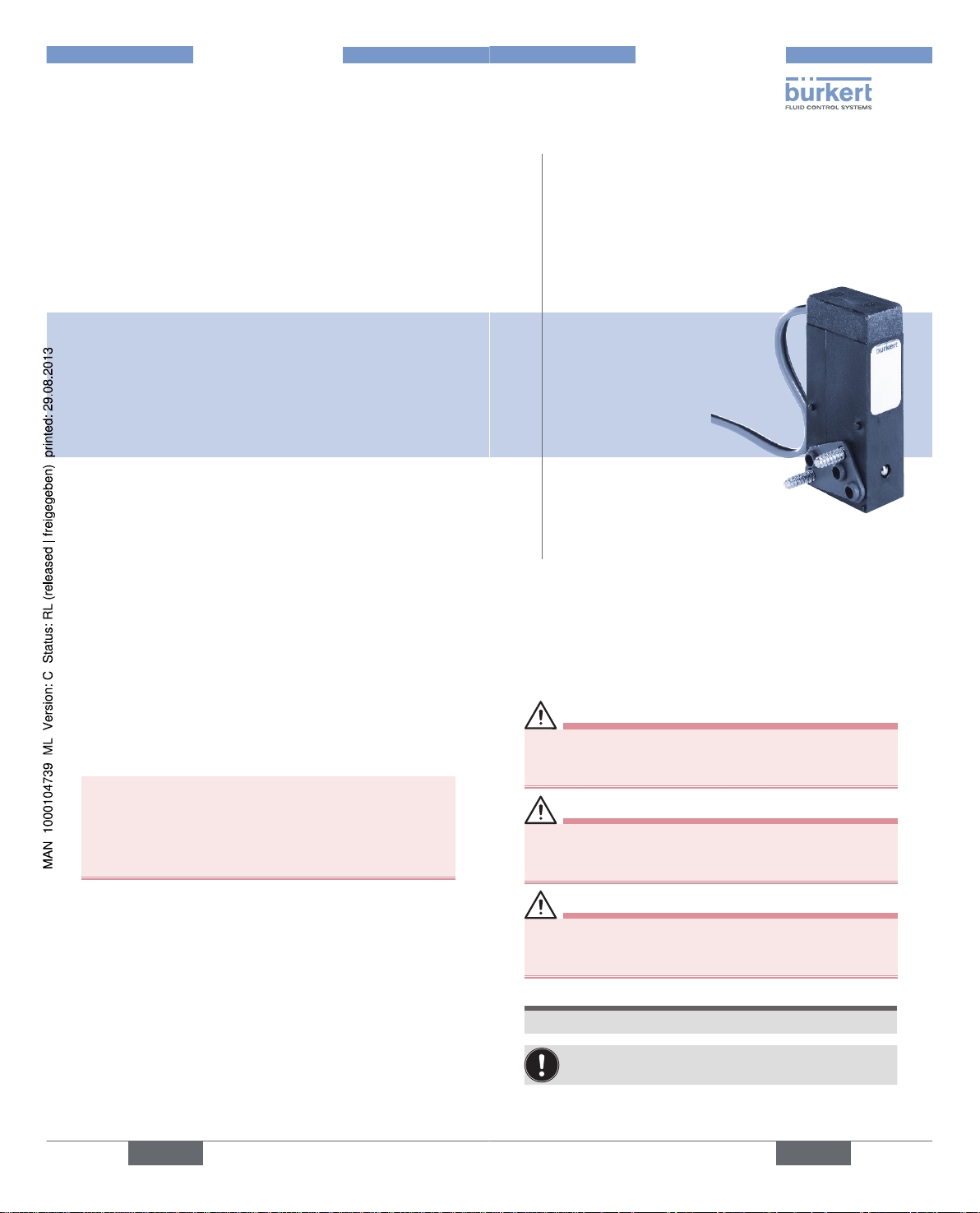
Type 6114
3/2-way flipper valve (horizontal)
3/2-Wege Flipperventil (liegend)
Soupape à languette 3/2 (horizontale)
english
2
OPERATING INSTRUCTIONS
The operating instructions describe the entire life cycle of the
device. Keep these instructions in a location which is easily
accessible to every user and make these instructions available
to every new owner of the device.
The operating instructions contain important safety
information!
Failure to observe these instructions may result in hazardous situations.
• The operating instructions must be read and under stood.
english
3
SYMBOLS
The following symbols are used in these instructions.
DANGER!
Warns of an immediate danger!
• Failure to observe the warning may result in a fatal or
serious injury.
WARNING!
Warns of a potentially dangerous situation!
• Failure to observe the warning may result in a serious
or fatal injury.
CAUTION!
Warns of a possible danger!
• Failure to observe this warning may result in a
moderately severe or minor injury.
NOTE!
Warns of damage to property!
Important tips and recommendations for safe and
problem-free operation of the device.
→ Designates a procedure which you must carry out.
Type 6114
Page 2
english
4
CORRECT USE
Incorrect use of the flipper valve 6114 can be
dangerous to people, nearby equipment and the
environment.
• The flipper valve Type 6114 was designed particularly
as a precontrol for tapware. It is not suitable for use
outdoors.
• The flipper valve must not be used in potentially
explosive areas.
• Do not use the device outdoors.
• Use according to the permitted data, operating conditions and conditions of use specified in the contract
documents and operating instructions.
• Correct transportation, correct storage and installation,
and careful operation and maintenance are essential for
reliable and problem-free operation.
• Use the device only as intended.
english
5
BASIC SAFETY INSTRUCTIONS
These safety instructions do not make allowance for any
• contingencies and events which may arise during the
installation, operation and maintenance of the devices.
• local safety regulations, whereby the operator is
responsible for their compliance, by the installation
personnel too.
Danger – high pressure!
• Before loosening the lines and valves, turn off the pressure and vent the lines.
Risk of burns/risk of fire if used continuously through
hot device surface!
• Keep the device away from highly flammable substances
and media and do not touch with bare hands.
english
6
General hazardous situations.
To prevent injury, ensure that:
• Do not make any external modifications to the device
housings.
• The system cannot be activated unintentionally.
• Installation and repair work may be carried out by authorised technicians only and with the appropriate tools.
• After an interruption in the power supply or pneumatic
supply, ensure that the process is restarted in a defined
or controlled manner.
• The device may be operated only when in perfect condition and in consideration of the operating instructions.
• The general rules of technology apply to application
planning and operation of the device.
english
7
GENERAL INFORMATION
Contact address:
Germany
Bürkert Fluid Control Systems
Sales Center
Chr.-Bürkert-Str. 13-17
D-74653 Ingelfingen
Tel.: +49 (0)7940 - 10 91 111
Fax: +49 (0)7940 - 10 91 448
E-mail: info@de.burkert.com
International
Contact addresses can be found on the final pages of the
printed operating instructions.
And also on the internet at: www.burkert.com
Warranty
The warranty is only valid if the device is used as intended in
accordance with the specified application conditions.
Information on the Internet
The operating instructions and data sheets for Type 6114 can
be found on the Internet at: www.burkert.com
Type 6114
Page 3
english
8
STRUCTURE AND FUNCTION
The flipper valve Type 6114 is a 3/2-way solenoid valve
which can be operated electrically (mono or bistable).
TECHNICAL DATA
Operating Conditions
WARNING!
Risk of injury due to malfunction.
Malfunction if used outside!
• Do not use Type 6114 outdoors and avoid heat sources
which may cause the permitted temperature range to
be exceeded.
Ambient temperature: 5 to +55 °C
Medium temperature: 5 to +55 °C FFKM
0 to +55 °C EPDM
Media: Compressed air lubricated,
non-lubricated or dry;
neutral liquids and gases (5 µm filtration);
technical vacuum
Protection class: IP65
Protection class: 3 as per VDE 0580
english
9
Mechanical Data
Dimensions See data sheet
Housing material PPS, fibre-glass reinforced
Sealing material EPDM / FFKM
WARNING!
Risk of injury from discharge of medium through
damaged seals.
Unsuitable medium may damage the sealing material
(brittleness, destruction, swelling).
• Use only media suitable for the sealing material.
• If you have any queries, please consult our staff.
english
10
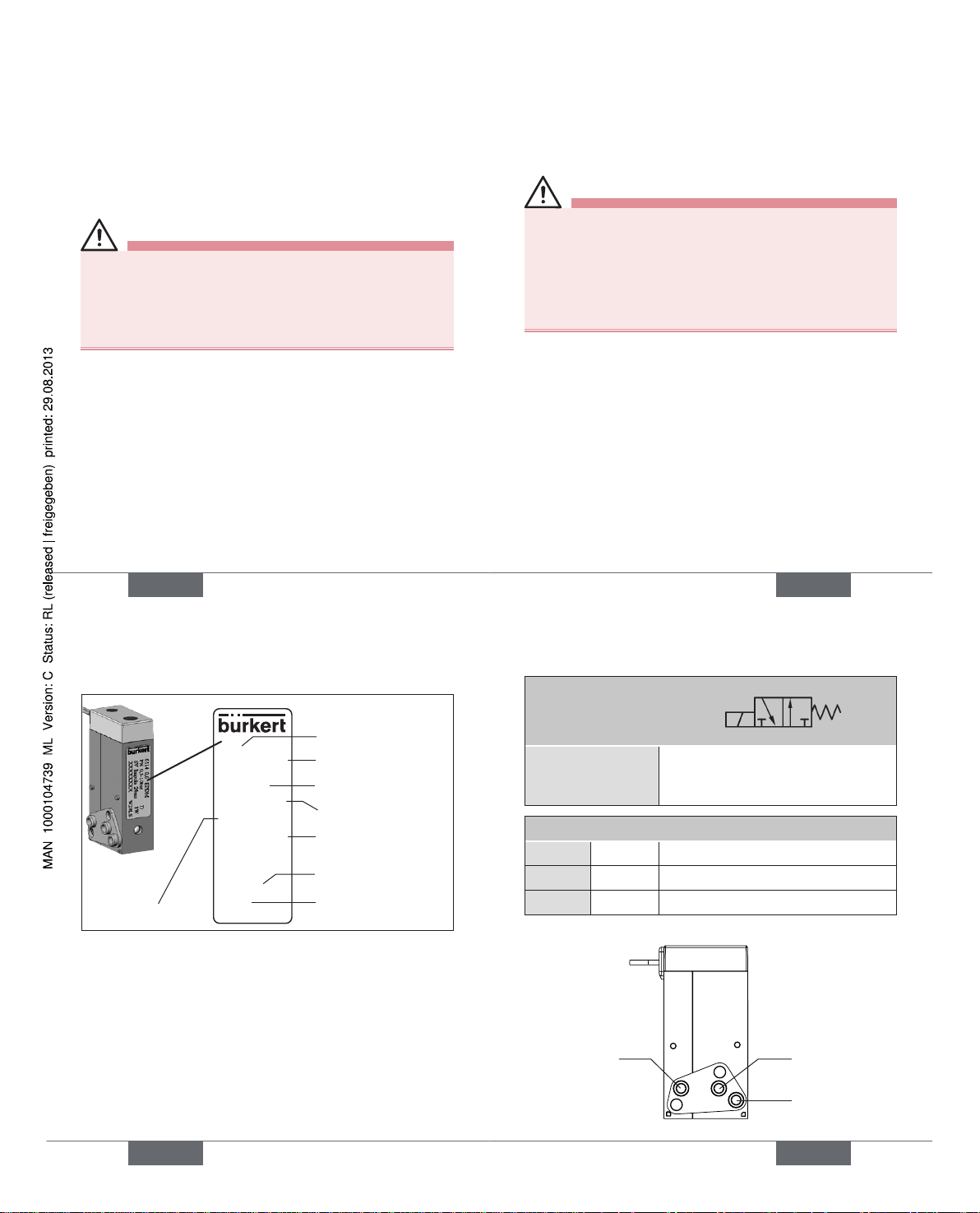
Type label
Example: Precontrol for bistable tapware (pulse version)
Nominal width
Operating principle
Pressure range
Voltage (±10 %)
Type
Output
6114 0,6 EPDM
PN 0,5-10bar D
6V Impuls 20ms 1W
XXXXXXXX W29LS
Order no.
Sealing material
english
11
Pneumatic Data
Operating principles D
B
P R
Precontrol for
tapware
3/2-way valve, direct-acting,
disconnected
output 2 pressurised
Fluid connections
1
P Pressure connection
2
B Working connection
3
R Exhaust air connection
Pressure range see type label
R seat
P seat
B
Type 6114
Page 4
english
12
ELECTRICAL DATA
Ensure that the polarity is correct, otherwise
the device will not function!
Observe color coding of the cable: (black / red)
Operating voltage According to type label
Standard version ± 10 %
Clocked version + 10 %
Nominal power 1.1 W
Nominal operating mode Continuous operation, ED 100 %
Actuation of bistable version:
Polarity
Identification
Pulse duration min. 20 ms
(black)
(red)
+
Valve (P seat) is
closed
Valve (R seat) is
open
–
Valve (P seat) is
open
Valve (R seat) is
closed
english
13
INSTALLATION
Safety Instructions
WARNING!
Risk of injury from improper assembly!
• Installation may be carried out by authorised technicians
only and with the appropriate tools!
Risk of injury from unintentional activation of the
system and an uncontrolled restart!
• Secure system from unintentional activation.
• Following assembly, ensure a controlled restart.
Fluid Installation
WARNING!
Risk of injury from high pressure!
• Before loosening the lines and valves, turn off the pressure
and vent the lines!
Important operating condition for the prevention of malfunctions: The valve must have a mini-
mum distance of 5 mm from other ferromagnetic
materials.
english
14
Installation location: any, drive preferably upwards.
Prior to the installation:
→ Clean any dirt off the pipelines and flange connections.
→ To prevent malfunctions, install a filter (5 µm) in front of
the valve.
Assembly of Type 6114:
(See diagram: Assembly drawing)
WARNING!
Danger - escaping medium!
Leaking connections if seal seated incorrectly.
• Ensure that the supplied sealing gasket is seated
correctly.
→ Insert the sealing gasket into the valve.
→ Correctly allocate the fluid connection configuration 1,
2 and 3 to the valve and the connection plate.
→ Drill holes according to the drill hole-pattern.
→ Screw valve onto the connection plate
→ Check valve for leakage.
english
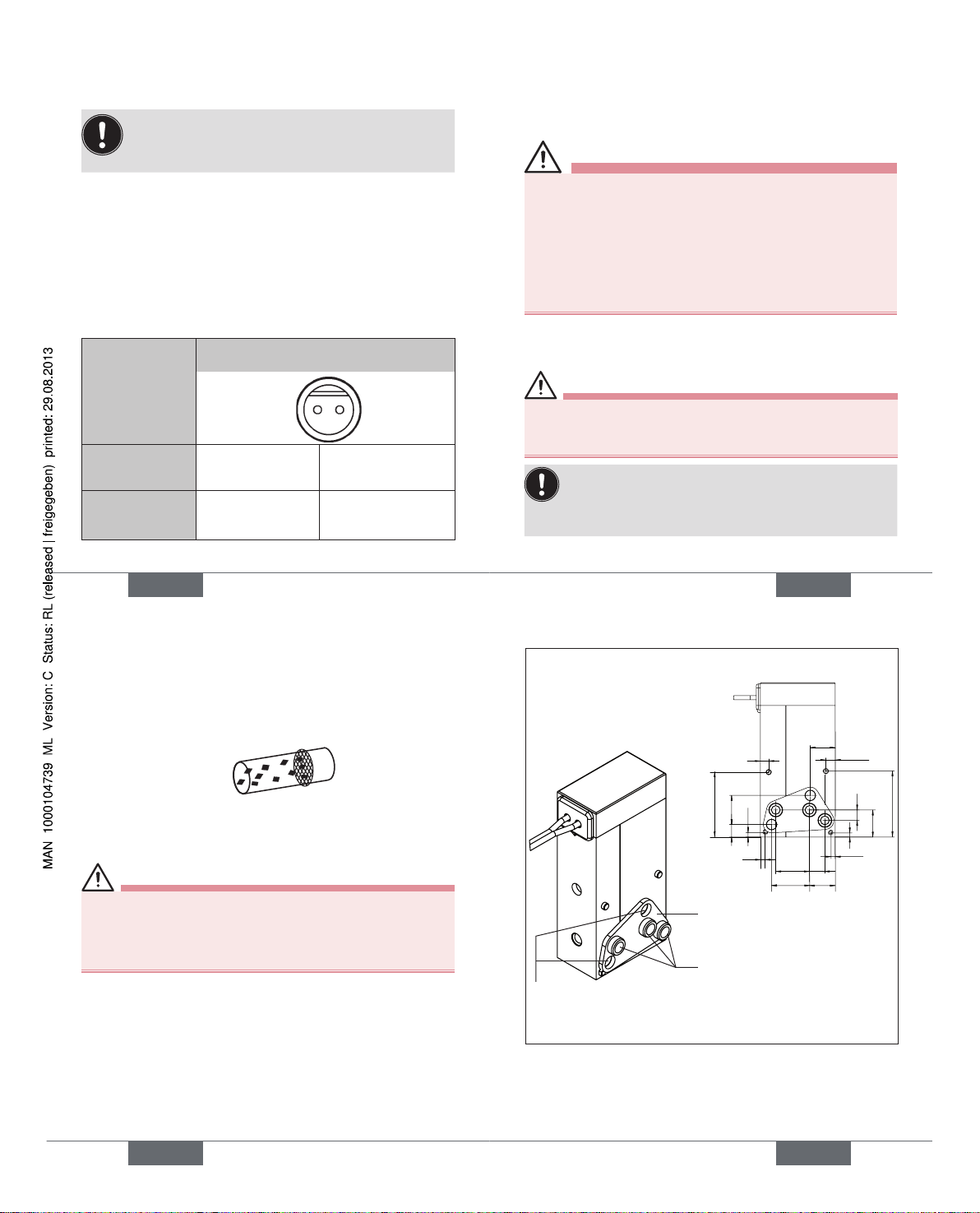
15
Valve with fastening elements
Fluid connections
(see "Pneumatic data")
2,25
2
15,6
6
6,2
3,7
8,1
1,1
9,1
1,1
7
3
2,5
6,5
15,85
1
1
Bore hole
illustration:
Bores for fastening
screws
Ø 2 mm
Sealing gasket
Figure: Assembly drawing
Type 6114
Page 5
english
16
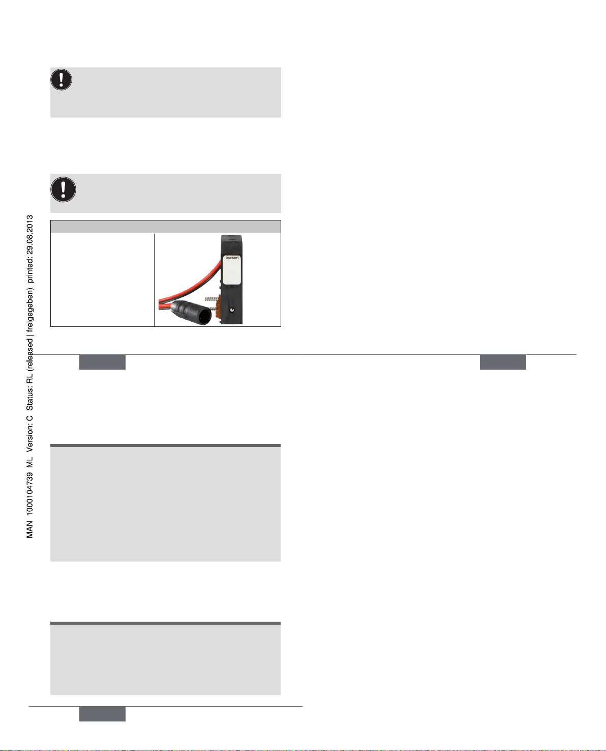
Electrical Installation
Important information for the problem-free functioning of the device:
The device is designed for battery voltage.
Use only direct voltage, residual ripple max. 10%!
Electrical connection:
Note the voltage and current type as specified on the type
label.
Ensure that the polarity is correct, otherwise
the device will not function!
Observe color coding: (black / red)
Connection with direct voltage
With plug and cable
english
17
MAINTENANCE, MALFUNCTIONS
The valve is maintenance-free under normal operating
conditions.
If the exterior is very dirty, it is recommended to clean it
with suitable cleaning agents. If required, determine the
suitability of the cleaning agent by conducting a test.
Malfunctions
If malfunctions occur, check
→ the line connections,
→ the operating pressure,
→ the power supply and valve control.
If the valve still does not switch, please contact your
Bürkert Service.
english
18
PACKAGING, TRANSPORT,
STORAGE
NOTE!
Transport damages!
Inadequately protected equipment may be damaged
during transport.
• During transportation protect the device against wet
and dirt in shock-resistant packaging.
• Avoid exceeding or dropping below the permitted
storage temperature.
Incorrect storage may damage the device.
• Store the device in a dry and dust-free location!
• Storage temperature: -20 – 65 °C.
DISPOSAL
→ Dispose of the device and packaging in an environmen-
tally friendly manner.
NOTE!
Damage to the environment caused by device components contaminated with media.
• Observe the currently valid regulations on disposal
and the environment in order to prevent damage to the
environment.
• Observe national waste disposal regulations.
Type 6114
Page 6

www.burkert.com
We reserve the right to make
technical changes without notice.
Technische Änderungen
vorbehalten.
Sous réserve de modification
techniques.
© 2008 - 2012 Bürkert Werke GmbH
Operating Instructions
1205/02_EU-ml_00805663 / Original DE
Bedienungsanleitung
Deutsch
Typ 6114
3/2-Wege Flipperventil (liegend)
deutsch
20
DIE BEDIENUNGSANLEITUNG
Die Bedienungsanleitung beschreibt den gesamten Lebenszyklus des Geräts. Bewahren Sie diese Anleitung so auf, dass
sie für jeden Benutzer gut zugänglich ist und jedem neuen
Eigentümer des Geräts wieder zur Verfügung steht.
Die Bedienungsanleitung enthält wichtige
Informationen zur Sicherheit!
Das Nichtbeachten dieser Hinweise kann zu gefährlichen
Situationen führen.
• Die Bedienungsanleitung muss gelesen und verstanden
werden.
21
deutsch
DARSTELLUNGSMITTEL
In dieser Anleitung werden folgende Darstellungsmittel
verwendet.
GEFAHR!
Warnt vor einer unmittelbaren Gefahr!
• Bei Nichtbeachtung sind Tod oder schwere
Verletzungen die Folge.
WARNUNG!
Warnt vor einer möglicherweise gefährlichen Situation!
• Bei Nichtbeachtung können schwere Verletzungen oder
Tod die Folge sein.
VORSICHT!
Warnt vor einer möglichen Gefährdung!
• Nichtbeachtung kann mittelschwere oder leichte
Verletzungen zur Folge haben.
HINWEIS!
Warnt vor Sachschäden!
Wichtige Tipps und Empfehlungen für die Sicherheit
und einwandfreie Funktion des Geräts.
→ markiert einen Arbeitsschritt den Sie ausführen müssen.
Typ 6114
Page 7

deutsch
22
BESTIMMUNGSGEMÄSSE
VERWENDUNG
Bei nicht bestimmungsgemäßem Einsatz des Flipperventils 6114 können Gefahren für Personen, Anlagen
in der Umgebung und die Umwelt entstehen.
• Das Flipperventil Typ 6114 wurde vorzugsweise als
Vorsteuerung für Wasserarmaturen konzipiert. Es ist
nicht für den Einsatz im Außenbereich geeignet.
• Das Flipperventil darf nicht in explosionsgefährdeten
Bereichen eingesetzt werden.
• Das Gerät nicht im Außenbereich einsetzen.
• Für den Einsatz die in den Vertragsdokumenten und der
Bedienungsanleitung spezifizierten zulässigen Daten,
Betriebs- und Einsatzbedingungen beachten.
• Voraussetzungen für den sicheren und einwandfreien
Betrieb sind sachgemäßer Transport, sachgemäße
Lagerung und Installation sowie sorgfältige Bedienung
und Instandhaltung.
• Setzen Sie das Gerät nur bestimmungsgemäß ein.
23
deutsch
GRUNDLEGENDE
SICHERHEITSHINWEISE
Diese Sicherheitshinweise berücksichtigen keine
• Zufälligkeiten und Ereignisse, die bei Montage, Betrieb
und Wartung der Geräte auftreten können.
• ortsbezogenen Sicherheitsbestimmungen, für deren
Einhaltung, auch in Bezug auf das Montagepersonal, der
Betreiber verantwortlich ist.
Gefahr durch hohen Druck!
• Vor dem Lösen von Leitungen und Ventilen den Druck
abschalten und Leitungen entlüften.
Verbrennungsgefahr/Brandgefahr bei Dauerbetrieb
durch heiße Geräteoberfläche!
• Das Gerät von leicht brennbaren Stoffen und Medien
fernhalten und nicht mit bloßen Händen berühren.
deutsch
24
Allgemeine Gefahrensituationen.
Zum Schutz vor Verletzungen ist zu beachten:
• Keine äußerlichen Veränderungen an den Gerätegehäusen vornehmen.
• Dass die Anlage nicht unbeabsichtigt betätigt werden
kann.
• Installations- und Instandhaltungsarbeiten dürfen nur von
autorisiertem Fachpersonal mit geeignetem Werkzeug
ausgeführt werden.
• Nach einer Unterbrechung der elektrischen oder pneumatischen Versorgung ist ein definierter oder kontrollierter Wiederanlauf des Prozesses zu gewährleisten.
• Das Gerät darf nur in einwandfreiem Zustand und unter
Beachtung der Bedienungsanleitung betrieben werden.
• Für die Einsatzplanung und den Betrieb des Geräts
müssen die allgemeinen Regeln der Technik eingehalten
werden.
25
deutsch
ALLGEMEINE HINWEISE
Kontaktadresse
Deutschland
Bürkert Fluid Control Systems
Sales Center
Christian-Bürkert-Str. 13-17
D-74653 Ingelfingen
Tel. : +49 (0) 7940 - 10 91 111
Fax: +49 (0) 7940 - 10 91 448
E-mail: info@de.burkert.com
International
Die Kontaktadressen finden Sie auf den letzten Seiten der
gedruckten Bedienungsanleitung.
Außerdem im Internet unter: www.burkert.com
Gewährleistung
Voraussetzung für die Gewährleistung ist der bestimmungsgemäße Gebrauch des Geräts unter Beachtung der spezifizierten Einsatzbedingungen.
Informationen im Internet
Bedienungsanleitungen und Datenblätter zum Typ 6114
finden Sie im Internet unter: www.buerkert.de
Typ 6114
Page 8

deutsch
26
AUFBAU UND FUNKTION
Das Flipperventil Typ 6114 ist ein 3/2-Wege Magnetventil,
das elektrisch (mono- oder bistabil) betrieben werden kann.
TECHNISCHE DATEN
Betriebsbedingungen
WARNUNG!
Verletzungsgefahr durch Funktionsausfall.
Funktionsausfall bei Einsatz im Außenbereich!
• Typ 6114 nicht im Außenbereich einsetzen.
• Wärmequellen, die zur Überschreitung des zulässigen
Temperaturbereichs führen können, vermeiden.
Umgebungstemperatur: 5 ... +55 °C
Mediumstemperatur: 5 ... +55 °C FFKM
0 ... +55 °C EPDM
Medien: Druckluft geölt, ölfrei oder trocken;
neutrale Flüssigkeiten und Gase
(5 µm-Filterung);
technisches Vakuum
Schutzart: IP65
Schutzklasse: 3 nach VDE 0580
27
deutsch
Mechanische Daten
Maße siehe Datenblatt
Gehäusematerial PPS, glasfaserverstärkt
Dichtungsmaterial EPDM / FFKM
WARNUNG!
Verletzungsgefahr durch Mediumsaustritt bei
beschädigten Dichtungen!
Ungeeignetes Medium kann zur Beschädigung des
Dichtungsmaterials führen (Versprödung, Zerstörung,
Quellung).
• Verwenden Sie nur für das Dichtungsmaterial geeignete Medien.
• Lassen Sie sich bei Unklarheiten von unseren Mitarbeitern beraten.
deutsch
28
Typschild
Beispiel: Vorsteuerung für Wasserarmaturen bistabil
(Impulsausführung)
Nennweite
Wirkungsweise
Druckbereich
Spannung (±10 %)
Typ
Leistung
6114 0,6 EPDM
PN 0,5-10bar D
6V Impuls 20ms 1W
XXXXXXXX W29LS
Bestell-Nr.
Dichtungsmaterial
29
deutsch
Pneumatische Daten
Wirkungsweise D
B
P R
Vorsteuerung für
Wasserarmaturen
3/2-Wege-Ventil, direktwirkend,
stromlos Ausgang 2 druckbeaufschlagt
Fluidische Anschlüsse
1
P Druckanschluss
2
B Arbeitsanschluss
3
R Abluftanschluss
Druckbereich siehe Typschild
R-Sitz
P-Sitz
B
Typ 6114
Page 9

deutsch
30
ELEKTRISCHE DATEN
Richtige Polarität ist Voraussetzung für die
Funktion des Geräts!
Farbliche Kennzeichnung des Kabels beachten:
(schwarz / rot)
Betriebsspannung entsprechend Typschild
Standardversion ± 10 %
getaktete Ausführung + 10 %
Nennleistung 1,1 W
Nennbetriebsart Dauerbetrieb, ED 100 %
Ansteuerung bistabile Ausführung:
Polung
Kennzeichnung
Impulsdauer mind. 20 ms
(schwarz)
(rot)
+
Ventil (P-Sitz)
wird geschlossen
Ventil (R-Sitz)
wird geöffnet
–
Ventil (P-Sitz)
wird geöffnet
Ventil (R-Sitz)
wird geschlossen
31
deutsch
MONTAGE
Sicherheitshinweise
WARNUNG!
Verletzungsgefahr bei unsachgemäßer Montage!
• Die Montage darf nur autorisiertes Fachpersonal mit
geeignetem Werkzeug durchführen!
Verletzungsgefahr durch ungewolltes Einschalten
der Anlage und unkontrollierten Wiederanlauf!
• Anlage vor unbeabsichtigtem Betätigen sichern.
• Nach der Montage einen kontrollierten Wiederanlauf
gewährleisten.
Fluidische Installation
WARNUNG!
Verletzungsgefahr durch hohen Druck.
• Vor dem Lösen von Leitungen und Ventilen Druck abschalten und entlüften!
Wichtige Betriebsbedingung zur Vermeidung von
Fehlfunktionen:
Das Ventil muss einen Mindestabstand von 5 mm zu
anderen ferromagnetischen Materialien haben.
deutsch
32
Einbaulage: beliebig, vorzugsweise Antrieb nach oben.
Vor der Montage:
→ Rohrleitungen und Flanschanschlüsse von eventuellen
Verschmutzungen säubern.
→ Zum Schutz vor Störungen vor das Ventil einen Filter
(5 µm) einbauen.
Montage Typ 6114:
(siehe Bild: Montagezeichnung)
WARNUNG!
Gefahr durch Mediumsaustritt!
Undichte Anschlüsse bei unkorrekt sitzender Dichtung.
• Achten Sie auf den richtigen Sitz der mitgelieferten
Dichtmatte.
→ Dichtmatte in das Ventil einlegen.
→ Fluidische Anschlussbelegung 1, 2 und 3 an Ventil und
Anschlussplatte richtig zuordnen.
→ Bohrungen gemäß Bohrbild anbringen.
→ Ventil auf Anschlussplatte schrauben
→ Ventil auf Dichtheit prüfen.
33
deutsch
Ventil mit Befestigungselementen
Fluidische Anschlüsse
(siehe „Pneumatische Daten“)
2,25
2
15,6
6
6,2
3,7
8,1
1,1
9,1
1,1
7
3
2,5
6,5
15,85
1
1
Bohrbild:
Bohrungen für
Befestigungsschrauben
Ø 2 mm
Dichtmatte
Bild: Montagezeichnung
Typ 6114
Page 10

deutsch
34
Elektrische Installation
Wichtiger Hinweis für die einwandfreie Funktion des
Geräts:
Das Gerät ist für Batteriespannung ausgelegt.
Nur Gleichspannung mit max. 10 % Restwelligkeit verwenden!
Elektrischer Anschluss:
Spannung und Stromart laut Typschild beachten.
Richtige Polarität ist Voraussetzung für die
Funktion des Geräts!
Farbliche Kennzeichnung beachten:
(schwarz / rot)
Anschluss mit Gleichspannung
Mit Stecker und Kabel
35
deutsch
WARTUNG, STÖRUNGEN
Das Ventil arbeitet unter Normalbedingungen wartungsfrei.
Bei starker äußerer Verschmutzung wird eine Reinigung mit
geeigneten Reinigungsmitteln empfohlen. Die Eignung des
Reinigungsmittels sollte ggf. per Test ermittelt werden.
Störungen
Überprüfen Sie bei Störungen
→ die Leitungsanschlüsse,
→ den Betriebsdruck,
→ die Spannungsversorgung und Ventilansteuerung.
Falls das Ventil dennoch nicht schaltet, wenden Sie sich
bitte an Ihren Bürkert-Service.
VERPACKUNG, TRANSPORT,
LAGERUNG
HINWEIS!
Transportschäden!
Unzureichend geschützte Geräte können durch den
Transport beschädigt werden.
• Gerät vor Nässe und Schmutz geschützt in einer stoßfesten Verpackung transportieren.
deutsch
36
• Eine Über- bzw. Unterschreitung der zulässigen Lager-
temperatur vermeiden.
Falsche Lagerung kann dem Gerät schaden.
• Gerät trocken und staubfrei lagern!
• Lagertemperatur: – 20 … 65 °C.
ENTSORGUNG
→ Entsorgen Sie das Gerät und die Verpackung
umweltgerecht.
HINWEIS!
Umweltschäden durch von Medien kontaminierte
Geräteteile.
• Halten Sie die geltenden Entsorgungsvorschriften und
Umweltbestimmungen ein, um Schäden an der Umwelt
zu vermeiden.
Beachten Sie die nationalen
Abfallbeseitigungsvorschriften.
Typ 6114
Page 11

www.burkert.com
We reserve the right to make
technical changes without notice.
Technische Änderungen
vorbehalten.
Sous réserve de modification
techniques.
© 2008 - 2012 Bürkert Werke GmbH
Operating Instructions
1205/02_EU-ml_00805663 / Original DE
Manuel d’utilisation
Français
Type 6114
Soupape à languette 3/2 (horizontale)
français
38
INSTRUCTIONS DE SERVICE
Les instructions de service décrivent le cycle de vie complet
de l’appareil. Conservez ces instructions de sorte qu’elles
soient accessibles à tout utilisateur et à disposition de tout
nouveau propriétaire.
Les instructions de service contiennent des informations importantes sur la sécurité !
Le non-respect de ces consignes peut entraîner des
situations dangereuses.
• Les instructions de service doivent être lues et
comprises.
39
français
MOYENS DE REPRÉSENTATION
Les moyens de représentation suivants sont utilisés dans
les présentes instructions de service.
DANGER !
Met en garde contre un danger imminent !
• Le non-respect peut entraîner la mort ou de graves
blessures.
AVERTISSEMENT !
Met en garde contre une situation éventuellement
dangereuse !
• Le non-respect peut entraîner de graves blessures ou
la mort.
ATTENTION !
Met en garde contre un risque possible !
• Le non-respect peut entraîner des blessures légères ou
de moyenne gravité.
REMARQUE !
Met en garde contre des dommages matériels !
Conseils et recommandations importants pour la
sécurité et le parfait fonctionnement de l’appareil.
→ Identifie une opération que vous devez effectuer.
Type 6114
Page 12

français
40
UTILISATION CONFORME
L’utilisation non conforme de la soupape à languette
type 6114 peut présenter des dangers pour les personnes, les installations proches et l’environnement.
• La soupape à languette type 6114 a été conçue de
préférence comme commande pilote pour des
robinetteries d’eau. Elle n’est pas destinée à être
utilisée à l’extérieur.
• La soupape à languette ne doit pas être utilisée dans des
zones présentant des risques d’explosion.
• N’utilisez pas l’appareil à l’extérieur.
• Lors de l’utilisation, il convient de respecter les données
et conditions d’utilisation et d’exploitation admissibles
spécifiées dans les instructions de service et dans les
documents contractuels.
• Les conditions pour l’utilisation sûre et parfaite sont un
transport, un stockage et une installation dans les règles
ainsi qu’une utilisation et maintenance parfaites.
• Veillez à ce que l’utilisation de l’appareil soit toujours
conforme.
41
français
CONSIGNES DE SÉCURITÉ
FONDAMENTALES
Ces consignes de sécurité ne tiennent pas compte
• des hasards et des événements pouvant survenir lors du
montage, de l’exploitation et de l’entretien des appareils.
• des prescriptions de sécurité locales que l’exploitant
est tenu de faire respecter par le personnel chargé du
montage.
Danger dû à la haute pression !
• Avant de desserrer les conduites et les soupapes, coupez
la pression et purgez l’air des conduites.
Risque de brûlures/d’incendie en fonctionnement
continu dû à des surfaces d’appareils brûlantes !
• Tenez les substances et les fluides facilement inflammables à l’écart de l’appareil et ne touchez pas ce dernier
à mains nues.
français
42
Situations dangereuses d’ordre général.
Pour prévenir les blessures, respectez ce qui suit :
• L’installation ne peut être actionnée par inadvertance.
• N’apportez pas de modifications à l’extérieur du boîtier
• Les travaux d’installation et de maintenance doivent être
effectués uniquement par des techniciens qualifiés et
habilités disposant de l’outillage approprié.
• Après une interruption de l’alimentation électrique ou
pneumatique, un redémarrage défini ou contrôlé du
processus doit être garanti.
• L’appareil doit être utilisé uniquement en parfait état et
en respectant les instructions de service.
• Les règles générales de la technique sont d’application
pour planifier l’utilisation et utiliser l’appareil.
43
français
REMARQUES GÉNÉRALES
Adresse
Allemagne
Bürkert Fluid Control Systems
Sales Center
Chr.-Bürkert-Str. 13-17
D-74653 Ingelfingen
Tél. : +49 (0)7940 - 10 91 111
Fax : +49 (0)7940 - 10 91 448
E-mail : info@de.burkert.com
International
Les adresses se trouvent aux dernières pages des instructions de service imprimées.
Également disponibles sur Internet à l’adresse suivante:
www.burkert.com
Garantie légale
La condition pour bénéficier de la garantie légale est l’utilisation conforme de l’appareil dans le respect des conditions
d’utilisation spécifiées.
Informations sur Internet
Vous trouverez les instructions de service et les fiches
techniques concernant le type 6114 sur Internet sous :
www.buerkert.fr
Type 6114
Page 13

français
44
STRUCTURE ET MODE DE
FONCTIONNEMENT
La soupape à languette type 6114 est une soupape
magnétique 3/2 pouvant être utilisée avec l’électricité
(monostable ou bistable).
CARACTÉRISTIQUES
TECHNIQUES
Conditions d’exploitation
AVERTISSEMENT !
Risque de blessures dû à une panne.
Panne lors de l’utilisation à l’extérieur !
• N’utilisez pas le type 6114 à l’extérieur et évitez les
sources de chaleur susceptibles d’entraîner un dépassement de la plage de température admissible.
Température ambiante : 5 ... +55 °C
Température du fluide : 5 ... +55 °C FFKM
0 ... +55 °C EPDM
Fluides : air comprimé lubrifié, exempt d’huile ou sec ;
liquides et gaz neutres (filtration 5 µm) ;
vide technique
45
français
Type de protection : IP65
Protection : 3 selon VDE 0580
Caractéristiques mécaniques
Dimensions voir fiche technique
Matériau du boîtier PPS, renforcé par fibres de verre
Matériau d’étanchéité EPDM / FFKM
AVERTISSEMENT !
Risque de blessures dû à la sortie de fluides causée
par l’endommagement des joints.
Un fluide non approprié peut endommager le matériau
d’étanchéité (fragilisation, destruction, gonflement).
• Utilisez uniquement des fluides adaptés au matériau
d’étanchéité.
• En cas de doute, faites-vous conseiller par nos
employés.
français
46
Plaque signalétique
Exemple : Commande pilote bistable pour robinetteries
d’eau (version à impulsions)
Diamètre nominal
Mode d’action
Plage de pression
Tension (±10 %)
Type
Puissance
6114 0,6 EPDM
PN 0,5-10bar D
6V Impuls 20ms 1W
XXXXXXXX W29LS
Référence
Matériau
d’étanchéité
47
français
Caractéristiques pneumatiques
Modes d’action D
B
P R
Commande pilote
pour robinetteries
d’eau
Soupape magnétique 3/2, à action
directe, pression appliquée sur
sortie 2 sans courant
Raccords fluides
1
P Raccord de pression
2
B Raccord de travail
3
R Raccord d’évacuation d’air
Plage de pression voir plaque signalétique
Siège R
Siège P
B
Type 6114
Page 14

français
48
CARACTÉRISTIQUES
ÉLECTRIQUES
La polarité correcte est la condition pour le bon
fonctionnement de l’appareil !
Respectez l’identification couleur du câble :
(noir / rouge)
Tension de service selon la plaque signalétique
version standard ± 10 %
version cadencée + 10 %
Puissance nominale 1,1 W
Mode opératoire nominal fonctionnement continu,
ED 100 %
Commande version bistable :
Polarité
Identification
Durée de l’impulsion au moins 20 ms
(noir) (rouge)
+
La soupape
(siège P) se ferme
La soupape
(siège R) s’ouvre
–
La soupape
(siège P) s’ouvre
La soupape
(siège R) se ferme
49
français
MONTAGE
Consignes de sécurité
AVERTISSEMENT !
Risque de blessures dû à un montage non conforme !
• Le montage doit être effectué uniquement par un personnel qualifié et habilité disposant de l’outillage approprié !
Risque de blessures dû à la mise en marche involontaire de l’installation et le redémarrage non contrôlé !
• Empêchez tout actionnement involontaire de
l’installation.
• Garantissez un redémarrage contrôlé après le
montage.
Installation fluide
AVERTISSEMENT !
Danger dû à la haute pression.
• Avant de desserrer les conduites et les soupapes, coupez
la pression et purgez l’air des conduites !
Condition d’exploitation importante pour éviter
les dysfonctionnements : la soupape doit respec-
ter une distance minimale de 5 mm par rapport aux
autres matériaux ferromagnétiques.
français
50
Position de montage : au choix, de préférence entraînement
vers le haut.
Avant le montage :
→ Nettoyez les tuyauteries et les raccordements à brides
afin d’enlever les éventuelles saletés.
→ Monter un filtre (5 µm) en amont de la soupape pour
protéger contre les
dysfonctionnements.
Montage type 6114 :
(voir fig. : plan de montage)
AVERTISSEMENT !
Danger dû à la sortie de fluide !
Raccordements non étanches suite au mauvais positionnement des joints.
• Veillez au bon positionnement du joint d’isolation fourni.
→ Placez le joint dans la soupape.
→ Affectez correctement les raccordements fluide 1, 2 et
3 à la soupape et à la plaque de connexion.
→ Effectuez les perçages conformément au gabarit de
perçage.
51
français
→ Vissez la soupape sur la plaque de connexion.
→ Contrôlez l’étanchéité de la soupape.
Soupape avec éléments de fixation
Raccords fluides
(voir « Caractéristiques
pneumatiques »)
2,25
2
15,6
6
6,2
3,7
8,1
1,1
9,1
1,1
7
3
2,5
6,5
15,85
1
1
Gabarit de
perçage :
Alésages pour vis de
fixation
Ø 2 mm
Joint d’isolation
Figure : plan de montage
Type 6114
Page 15

français
52
Installation électrique
Remarque importante concernant le parfait fonctionnement de l’appareil :
L’appareil est conçu pour la tension de la batterie.
Ondulation résiduelle maxi 10 %
Raccordement électrique :
Respectez la tension et le type de courant selon la plaque
signalétique.
La polarité correcte est la condition pour le bon
fonctionnement de l’appareil !
Respectez l’identification couleur : (noir / rouge)
Raccordement avec tension continue
Avec connecteur et
câble
53
français
ENTRETIEN, PANNES
Dans des conditions normales, la soupape ne nécessite
aucun entretien.
En cas de fort encrassement extérieur, le nettoyage avec
des produits de nettoyage appropriés est recommandé. Le
cas échéant, effectuez un test afin de vérifier si le produit
de nettoyage est adapté.
Pannes
En présence de pannes, vérifiez
→ les raccords de câbles
→ la pression de service
→ l’alimentation en tension et la commande de la
soupape.
Si malgré tout la soupape ne fonctionne pas, veuillez
contacter votre service après-vente Bürkert.
EMBALLAGE, TRANSPORT,
STOCKAGE
REMARQUE !
Dommages dus au transport !
Les appareils insuffisamment protégés peuvent être
endommagés pendant le transport.
• Transportez l’appareil à l’abri de l’humidité et des
impuretés et dans un emballage résistant aux chocs.
français
54
• Évitez le dépassement vers le haut ou le bas de la tem-
pérature de stockage admissible.
Un mauvais stockage peut endommager l’appareil.
• Stockez l’appareil au sec et à l’abri des poussières !
• Température de stockage : -20 … 65 °C.
ÉLIMINATION
→ Éliminez l’appareil et l’emballage dans le respect de
l’environnement.
REMARQUE !
Dommages à l’environnement causés par des pièces
d’appareil contaminées par des fluides.
• Respectez les prescriptions en matière d’élimination des
déchets et de protection de l’environnement en vigueur
pour éviter de nuire à l’environnement.
Respectez les prescriptions nationales en matière
d’élimination des déchets.
Type 6114
 Loading...