

Page 1
PTB 01 ATEX 2101
Device with II 2G/D Ex i approval
Geräte mit II 2G/D Ex i Zulassung
Appareils avec mode de protection II 2G/D Ex i
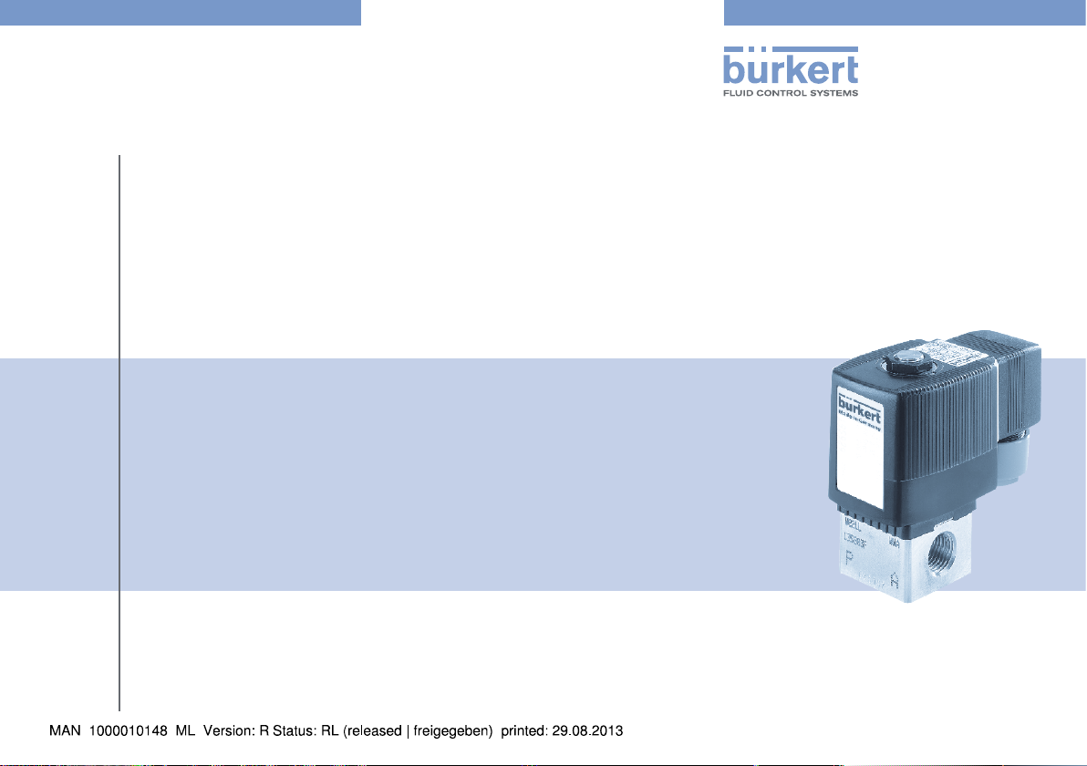
Example / Beispiel / Exemple
Type 6013
Operating Instructions
Bedienungsanleitung
Manuel d‘utilisation
Page 2
We reserve the right to make technical changes without notice.
Technische Änderungen vorbehalten.
Sous réserve de modifications techniques.
© 2002-2012 Bürkert Werke GmbH
Operating Instructions 1206/17_EU-ML_00804424 / Original DE
Page 3

PTB 01 ATEX 2101
Contents
1. OPERATING INSTRUCTIONS ...................................................................4
1.1. Symbols
2. AUTHORIZED USE .........................................................................................5
2.1. Restrictions
2.2. Ex approval ........................................................................................5
3. BASIC SAFETY INSTRUCTIONS .............................................................6
4. GENERAL INFORMATION ...........................................................................7
4.1. Contact addresses .......................................................................... 7
4.2. Warranty
4.3. Information on the Internet ............................................................. 7
5. APPLICATION CONDITIONS OF THE DEVICES .............................7
5.1. Use in the hazardous area .............................................................. 7
5.2. Operation only with associated valve ..........................................7
5.3. Individual assembly, block assembly ............................................7
6. TECHNICAL DATA ...........................................................................................8
6.1. Conformity
6.2. Standards
6.3. Licences
6.4. Operating conditions ....................................................................... 8
6.5. Use in potentially explosive areas of gas .................................... 9
6.6. Use in potentially explosive areas of dust .................................11
..............................................................................................4
........................................................................................5
.............................................................................................7
.........................................................................................8
........................................................................................... 8
............................................................................................. 8
7. INSTALLATION ...............................................................................................12
7.1. Safety instructions .........................................................................12
7.2. Installation of Type 6013 ..............................................................12
7.3. Line connector ................................................................................13
8. START-UP
8.1. Safety instructions .........................................................................13
8.2. Start-up
9. MAINTENANCE, TROUBLESHOOTING ............................................ 14
9.1. Safety instructions .........................................................................14
9.2. Maintenance work ..........................................................................14
9.3. Troubleshooting
10. TRANSPORT, STORAGE, DISPOSAL .............................................. 14
......................................................................................................... 13
............................................................................................13
..............................................................................14
english
3
Page 4

PTB 01 ATEX 2101
Operating instructions
1. OPERATING INSTRUCTIONS
The operating instructions describe the entire life cycle of the device.
Keep these instructions in a location which is easily accessible to
every user and make these instructions available to every new owner
of the device.
The operating instructions contain important safety
information!
Failure to observe these instructions may result in hazardous
situations.
The operating instructions must be read and understood.
•
1.1. Symbols
DANGER!
Warns of an immediate danger!
• Failure to observe the warning may result in a fatal or serious
injury.
WARNING!
Warns of a potentially dangerous situation!
• Failure to observe the warning may result in serious injuries or
death.
CAUTION!
Warns of a possible danger!
• Failure to observe this warning may result in a medium or minor
injury.
NOTE!
Warns of damage to property!
• Failure to observe the warning may result in damage to the
device or the equipment.
Indicates important additional information, tips and
recommendations.
Refers to information in these operating instructions or in
other documentation.
→ designates a procedure which you must carry out.
4
english
Page 5

PTB 01 ATEX 2101
Authorized use
2. AUTHORIZED USE
Unauthorized use of the device Type 6013 may be dangerous
to people, nearby equipment and the environment.
• The device is used exclusively as a solenoid valve for media permitted according to data sheet and for use in Group II Category
2 G (zones 1 and 2), temperature class T5 or T6 or 2 D (zones
21 and 22), temperature 80 °C (see specifications on the
approval plate).
• The device may be used only for the applications designated in
chapter „5. Application conditions of the devices“ and in conjunction with third-party devices and components recommended and
authorized by Bürkert.
• The applied protection class is the intrinsic safety (Ex ia) for coils
with cable connection or connection via flat plug by means of
device socket.
• The faultless and reliable operation of the system assumes correct transportation, correct storage and installation as well as
careful operation and maintenance. Any other use is regarded as
unauthorized. Bürkert is not liable for any resulting damage. The
user alone bears the risk.
• Only use the device for its intended purpose.
2.1. Restrictions
If exporting the system/device, observe any existing restrictions.
2.2. Ex approval
The Ex approval is only valid if the modules and components authorized
by Bürkert are used as described in these operating instructions.
Type 6013 may be used only in combination with the additional components released by Bürkert, otherwise the Ex approval will be voided!
If any unauthorized changes are made to the device, modules or components, the Ex approval will also be voided.
english
5
Page 6

3. BASIC SAFETY
INSTRUCTIONS
These safety instructions do not make allowance for any
• Contingencies and events which may arise during the installation,
operation and maintenance of the devices.
• Local safety regulations – the operator is responsible for observing
these regulations, also with reference to the installation personnel.
Danger of explosion!
• The device is a closed system and must not be modified in any
way.
A device which has already been used in a non-hazardous “i” circuit
must no longer be used in the hazardous “i” circuit, as safety cannot
be guaranteed.
• Use the device in the hazardous “i” circuit only.
• Devices which were used in a non-hazardous “i” circuit must be
identified after they have been removed, denoting that their use is
prohibited in the hazardous “i” circuit.
Danger – high pressure!
When reaching into the system, there is an acute risk of injury.
• Before dismounting pneumatic lines and valves, turn off the pressure and vent the lines.
• During the installation, make certain the flow direction is correct.
• Observe applicable accident prevention and safety regulations
for pressurized devices.
PTB 01 ATEX 2101
Basic safety instructions
Danger of explosion caused by electrostatic charge!
If there is a sudden discharge from electrostatically charged
devices or persons, there is a danger of explosion in the Ex area.
• Using suitable measures, ensure that no electrostatic charges
can occur in the Ex area.
• Clean the device surface by gently wiping it with a damp or antistatic cloth only.
General Hazardous Situations.
To prevent injuries:
• Ensure that the system cannot be activated unintentionally.
• Installation and maintenance work may be carried out only by
authorized technicians with the appropriate tools.
• After an interruption in the power supply or pneumatic supply,
ensure that the process is restarted in a defined or controlled
manner.
The device may be operated only when in perfect condition and
•
in consideration of the operating instructions.
• The general rules of technology must be observed for application
planning and operation of the device.
Failure to observe this operating manual and its operating
instructions as well as unauthorized tampering with the device
release us from any liability and also invalidate the warranty
covering the devices and accessories!
6
english
Page 7
PTB 01 ATEX 2101
General information
4. GENERAL INFORMATION
4.1. Contact addresses
Germany
Bürkert Fluid Control Systems
Sales Center
Christian-Bürkert-Str. 13-17
D-74653 Ingelfingen
Tel. + 49 (0) 7940 - 10 91 111
Fax + 49 (0) 7940 - 10 91 448
E-mail: info@de.buerkert.com
International
Contact addresses can be found on the final pages of the printed
operating instructions.
And also on the Internet at: www.burkert.com
4.2. Warranty
The warranty is only valid if the device is used as intended in accordance
with the specified application conditions.
4.3. Information on the Internet
The operating instructions and data sheets for Type 6013 can be found
on the Internet at: www.burkert.com
5. APPLICATION CONDITIONS OF
THE DEVICES
5.1. Use in the hazardous area
The device may be used either in the hazardous area of gas
or dust but not in a hybrid mixture.
5.2. Operation only with associated
valve
The solenoid coils may be operated only with a valve body with minimum
dimensions: 32 mm x 32 mm x 10 mm made of metal or plastic. A larger
valve body with better heat conductivity may be attached at any time.
5.3. Individual assembly, block
assembly
• Solenoid coils type AC10 - 5: are suitable for individual and block
assembly.
Solenoid coils type AC10 - 6: are suitable only for individual assembly
•
NOTE!
For block assembly observe the following:
• Dimensions of the valve body: 32 mm x 32 mm x 10 mm.
• Material of the valve body: Brass (MS), plastic (PA 6 GV),
stainless steel.
english
7
Page 8

PTB 01 ATEX 2101
PTB IECEx 10.0019
0102
PTB 01 ATEX 2101
Technical data
6. TECHNICAL DATA
6.1. Conformity
The device conforms to the EC directives according to the EC Declaration of Conformity.
6.2. Standards
The conformity with EC guidelines is guaranteed in accordance with
standards:
EN 60079-0, EN 60079-11
•
6.3. Licences
The EC type-examination certificate PTB 01 ATEX 2101 was issued
by the
PTB (Physikalisch Technische Bundesanstalt)
Bundesallee 100
38116 Braunschweig
which also audits production (CE 102).
The EC type-examination certificate can be found on the Internet at:
www.burkert.com
6.4. Operating conditions
WARNING!
Danger of explosion!
It is highly risky to exceed the technical data indicated on the
rating plate!
• Never exceed the technical data indicated on the rating plate.
CE identification
IECEx approval number
PTB
approval number
Rating plate
Fuse
0,08
A
Fig. 1: Location of the rating plate
8
english
Page 9

MADE IN GERMANY
PTB 01 ATEX 2101
Technical data
6.4.1. Rating plate
Drawing-No. of coil
Designation IECEx-protection
Designation Ex-protection
II 2G
Ex ia IIC T6 Gb
II 2D
Ex ia IIIC T80°C Db
AC10-Z3-6-PD94 IP54
P,U,I,Tamb s.manual
S/N
999999 W24LA
Identnumber, production date
Serial number
Technical data (see chapter 6.5 and 6.6)
Fig. 2: Description of the rating plate
6.5. Use in potentially explosive
areas of gas
The device may be used either in the hazardous area of gas
or dust but not in a hybrid mixture.
6.5.1. Electrical data
Electrical data for ignition protection type Ex “ia” and gas group II C:
Coil
size
5
6
L x W x H
[mm]
45 x 32 x 41 160
78 x 32 x 41 220
50 x 40 x 41 210
83 x 40 x 41 270
Mass
[g]
Encoding Structure Temp.
PD89
PE28 T5
PD93
PE29 T5
PD94
PE30 T5
PD95
PE31 T5
Diodes in the
coil
Diodes in the
device socket
Diodes in the
coil
Diodes in the
device socket
class
T6
T6
T6
T6
english
9
Page 10

PTB 01 ATEX 2101
Technical data
6.5.2. Safety data
Group: II C
Category: 2 G
Ignition protection type: Ex ia
Temperature class: T5 or T6
Max. permitted input voltage (Ui): 35 V
Max. permitted input current (Ii): 0.9 A
Max. permitted input power (Pi): 1.1 W (AC10 - 5)
2.1 W (AC10 -6)
Inductance (Li): ~ 0
Capacity (Ci): ~ 0
The maximum permitted voltages and the associated shortcircuit currents can be found in Table A1 in the standard EN
60079-11 for the corresponding gas group.
Value pairs for the ignition protection type Ex ia II C (example):
Voltage value [V] = U
Current value [A] = I
Voltage value [V] = U
Current value [A] = I
i
i
i
i
15 18 20 22
0.9 0.44 0.309 0.224
25 28 30 35
0.158 0.120 0.101 0.073
6.5.3. Operational data
The coils of type AC10 are available in two versions:
• Version for use with 300 Ω supply module (300 Ω barrier),
• Version for use with other authorized supply modules (e.g. 8 x remote
I/O from Stahl).
Version Resis-
Version which
uses 300 Ω
supply module
High-resistance version
tance
R20 [Ω]
310 9 29 10
481 11.1 23 11
Minimum
clamping
voltage [V]
Minimum
current [mA]
Distinctive
code
number
The maximum voltage and current values are specified by
the permitted electrical equipment.
6.5.4. Permitted ambient temperature
Montage Temper-
ature class
Individual
T6 -40 ... +60 °C -40 ... +60 °C
assembly
Block assembly T6 -40 ... +60 °C Not possible
Individual
T5 -40 ... +75 °C -40 ... +75 °C
assembly
Block assembly T5 -40 ... +75 °C Not possible
Protection class: For Ex “i” at least IP20 in accordance with
EN 60529 (DIN VDE 0470 Part 1)
AC10 - 5 AC10 - 6
10
english
Page 11

PTB 01 ATEX 2101
Technical data
6.6. Use in potentially explosive
areas of dust
The device may be used either in the hazardous area of gas
or dust but not in a hybrid mixture.
6.6.1. Electrical data
Electrical data for ignition protection type Ex ia:
Coil
size
* Max. surface temperature of the coil [T]
L x W x H
45 x 32 x 41 160
5
78 x 32 x 41 220
50 x 40 x 41 210
6
83 x 40 x 41 270
[mm]
Mass
Encoding Structure Temp.
[g]
PD89
PE28
PD93
PE29
PD94
PE30
PD95
PE31
Diodes in the
coil
Diodes in the
device socket
Diodes in the
coil
Diodes in the
device socket
of the
coil *
+80 °C
6.6.2. Safety data
Group: IIIC
Category: 2 D
Ignition protection type: Ex ia
Max. surface temperature: T = 80 °C
The coils of type AC10 - 5 and AC10 - 6 in ignition protection type “i”
may be connected to circuits which have the following maximum values:
Max. permitted input voltage (Ui): 35 V
Max. permitted input current (Ii): 0.9 A
Max. permitted input power (Pi): 690 mW
Inductance (Li): ~ 0
Capacity (Ci): ~ 0
Type AC10-6 is suitable for individual assembly only.
6.6.3. Permitted ambient temperature
Montage Temper-
ature class
Individual
T6 -40 ... +60 °C -40 ... +60 °C
assembly
Block assembly T6 -40 ... +60 °C Not possible
AC10 - 5 AC10 - 6
english
11
Page 12

PTB 01 ATEX 2101
Installation
7. INSTALLATION
7.1. Safety instructions
DANGER!
Danger of explosion!
The device is a closed system. It must not be removed.
The following safety instructions must be observed:
• The surface of the device may become electrostatically charged.
In potentially explosive areas the surface of the devices may be
cleaned with a damp or an anti-static cloth only.
• Only specified cables and lines may be used.
• The operator must ensure an adequate strain relief.
• Observe the maximum thermal load of the installed cables and
lines.
The inserted seal must be adjusted to the diameter of the cable
•
/ line.
The rated cross-section of the cables / line cores must be at
least 0.25 mm².
• Screws for attaching the cover of the terminal box must be
tightened to a torque of 100 Ncm (± 5 %).
DANGER!
Risk of explosion due to overheating!
In the case of battery assembly observe the following data of the valves:
• Dimension of the valve body: 32 mm x 32 mm x 10 mm.
• Material of the valve body: Brass (MS), stainless steel (VA) or
plastic (PA 6 GV).
WARNING!
Danger – high pressure!
When reaching into the system, there is an acute risk of injury.
• Before dismounting pneumatic lines and valves, turn off the pressure and vent the lines.
• During the installation, make certain the flow direction is correct.
• Observe applicable accident prevention and safety regulations
for pressurized devices.
7.2. Installation of Type 6013
Any installation position.
Preferably with magnet system face up.
1. Clean pipelines.
2. Any installation position
→ Preferential direction with actuator face up.
3. Connect dirt trap upstream
→ Observe direction of flow!
12
english
Page 13

PTB 01 ATEX 2101
Start-up
4. Seal
→ PTFE.
5. Screw in pipelines
→ Observe direction of flow!
6. Install / remove.
NOTE!
Information for devices with connecting cable:
Connecting cable and coil are encapsulated. They must not be
removed!
Always connect protective conductor!
7. Connect to power supply.
7.3. Line connector
• PE28, PE30, PD89 and PD94: via flat plug by means of device
socket type 2508 in accordance with DIN EN 175301-803,
shape A.
• PE29, PE31, PD93 and PD95: on the molded cable.
8. START-UP
8.1. Safety instructions
WARNING!
Risk of injury from improper operation!
Improper operation may result in injuries as well as damage to the
device and the area around it.
• Before start-up, ensure that the operating personnel are familiar
with and completely understand the contents of the operating
instructions.
Observe the safety instructions and intended use.
•
• Only adequately trained personnel may start up the equipment/
the device.
8.2. Start-up
Before starting up the device, ensure that:
• the device has been installed correctly,
• the connection has been made properly,
• the device is not damaged,
• all screws have been tightened.
• fit cable bushing according to the operating instructions for the
device.
english
13
Page 14

PTB 01 ATEX 2101
Maintenance, Troubleshooting
9. MAINTENANCE,
TROUBLESHOOTING
9.1. Safety instructions
WARNING!
Risk of injury from improper servicing, repairs and
maintenance!
The device may be serviced and maintained by authorized techni-
•
cians only and with the appropriate tools!
• The unit may be repaired by the manufacturer only!
9.2. Maintenance work
The devices are maintenance-free when operated under the conditions described in this manual.
9.3. Troubleshooting
If malfunctions occur, ensure that:
• the device has been installed correctly,
• the connection has been made properly,
• the device is not damaged,
• all screws have been tightened,
• the voltage and pressure have been switched on,
• the pipelines are free.
10. TRANSPORT, STORAGE,
DISPOSAL
NOTE!
Transport damages!
Inadequately protected equipment may be damaged during
transport.
During transportation protect the device against wet and dirt in
•
shock-resistant packaging.
• Avoid exceeding or dropping below the allowable storage
temperature.
Incorrect storage may damage the device.
• Store the device in a dry and dust-free location!
• Storage temperature: -40 … +55 °C.
Damage to the environment caused by device components
contaminated with media.
• Ensure the device and packaging are disposed of in an environmentally sound manner.
• Observe applicable regulations relating to refuse disposal and
the environment.
14
english
Page 15

PTB 01 ATEX 2101
Inhaltsverzeichnis
1. DIE BEDIENUNGSANLEITUNG ............................................................ 16
1.1. Darstellungsmittel
2. BESTIMMUNGSGEMÄSSE VERWENDUNG ...................................17
2.1. Beschränkungen
2.2. Ex-Zulassung
3. GRUNDLEGENDE SICHERHEITSHINWEISE ................................. 18
4. ALLGEMEINE HINWEISE .......................................................................... 19
4.1. Kontaktadresse
4.2. Gewährleistung...............................................................................19
4.3. Informationen im Internet ..............................................................19
5. EINSATZBEDINGUNGEN DER GERÄTE........................................... 19
5.1. Einsatz im Ex-Bereich ....................................................................19
5.2. Betrieb nur mit zugehörigem Ventil ............................................19
5.3. Einzelmontage, Blockmontage ....................................................19
6. TECHNISCHE DATEN ................................................................................20
6.1. Konformität
6.2. Normen
6.3. Zulassungen
6.4. Betriebsbedingungen
6.5. Einsatz in gasexplosionsgefährdeten Bereichen ....................21
6.6. Einsatz in staubexplosionsgefährdeten Bereichen .................23
.............................................................................................20
...........................................................................16
............................................................................17
...................................................................................17
...............................................................................19
.......................................................................................20
....................................................................................20
....................................................................20
7. MONTAGE ........................................................................................................24
7.1. Sicherheitshinweise
7.2. Montage des Typs 6013 ..............................................................24
7.3. Leitungsanschluss
8. INBETRIEBNAHME
8.1. Sicherheitshinweise
8.2. Inbetriebnahme
9. WARTUNG, FEHLERBEHEBUNG .........................................................26
9.1. Sicherheitshinweise
9.2. Wartungsarbeiten
9.3. Fehlerbehebung
10. TRANSPORT, LAGERUNG, VERPACKUNG .................................. 26
.......................................................................24
.........................................................................25
...................................................................................... 25
.......................................................................25
...............................................................................25
.......................................................................26
...........................................................................26
..............................................................................26
deutsch
15
Page 16

PTB 01 ATEX 2101
Die Bedienungsanleitung
1. DIE BEDIENUNGSANLEITUNG
Die Bedienungsanleitung beschreibt den gesamten Lebenszyklus
des Geräts. Bewahren Sie diese Anleitung so auf, dass sie für jeden
Benutzer gut zugänglich ist und jedem neuen Eigentümer des Geräts
wieder zur Verfügung steht.
Die Bedienungsanleitung enthält wichtige Informationen zur
Sicherheit!
Das Nichtbeachten dieser Hinweise kann zu gefährlichen Situationen
führen.
Die Bedienungsanleitung muss gelesen und verstanden werden.
•
1.1. Darstellungsmittel
GEFAHR!
Warnt vor einer unmittelbaren Gefahr!
• Bei Nichtbeachtung sind Tod oder schwere Verletzungen die
Folge.
WARNUNG!
Warnt vor einer möglicherweise gefährlichen Situation!
• Bei Nichtbeachtung drohen schwere Verletzungen oder Tod.
VORSICHT!
Warnt vor einer möglichen Gefährdung!
• Nichtbeachtung kann mittelschwere oder leichte Verletzungen
zur Folge haben.
HINWEIS!
Warnt vor Sachschäden!
• Bei Nichtbeachtung kann das Gerät oder die Anlage beschädigt
werden.
Bezeichnet wichtige Zusatzinformationen, Tipps und
Empfehlungen.
Verweist auf Informationen in dieser Bedienungsanleitung
oder in anderen Dokumentationen.
→ markiert einen Arbeitsschritt, den Sie ausführen müssen.
16
deutsch
Page 17

PTB 01 ATEX 2101
Bestimmungsgemäße Verwendung
2. BESTIMMUNGSGEMÄSSE
VERWENDUNG
Bei nicht bestimmungsgemäßem Einsatz des Geräts Typ 6013
können Gefahren für Personen, Anlagen in der Umgebung und
die Umwelt entstehen.
• Das Gerät dient ausschließlich als Magnetventil für die laut
Datenblatt zulässigen Medien und für den Einsatz in Gruppe II
Kategorie 2 G (Zone 1 und 2), Temperaturklasse T5 oder T6 bzw.
2 D (Zone 21 und 22), Temperatur 80 °C (siehe Angaben auf dem
Zulassungsschild).
• Das Gerät darf nur für die im Kapitel „5. Einsatzbedingungen
der Geräte“ vorgesehenen Einsatzfälle und in Verbindung mit
von Bürkert empfohlenen bzw. zugelassenen Fremdgeräten und
-komponenten verwendet werden.
• Die angewandte Schutzart ist die Eigensicherheit (Ex ia) für Spulen mit Kabelanschluss oder Anschluss über Flachstecker mittels
Gerätesteckdose.
Der einwandfreie und sichere Betrieb des Systems setzt
•
sachgemäßen Transport, sachgemäße Lagerung und Installation sowie sorgfältige Bedienung und Instandhaltung voraus.
Eine andere oder darüber hinausgehende Benutzung gilt als nicht
bestimmungsgemäß. Für hieraus resultierende Schäden haftet
Bürkert nicht. Das Risiko trägt allein der Anwender.
• Das Gerät nur bestimmungsgemäß einsetzen.
2.1. Beschränkungen
Bei der Ausfuhr des Systems/Geräts gegebenenfalls bestehende
Beschränkungen beachten.
2.2. Ex-Zulassung
Die Ex-Zulassung ist nur gültig, wenn die von Bürkert zugelassenen
Module und Komponenten so verwendet werden, wie es in dieser
Bedienungsanleitung beschrieben ist.
Der Typ 6013 darf nur in Kombination mit den von Bürkert freigegebenen Zusatzkomponenten eingesetzt werden, andernfalls erlischt die
Ex-Zulassung!
Bei unzulässigen Veränderungen am Gerät, Modulen oder Komponenten erlischt die Ex-Zulassung ebenfalls.
deutsch
17
Page 18

3. GRUNDLEGENDE
SICHERHEITSHINWEISE
Diese Sicherheitshinweise berücksichtigen keine
• Zufälligkeiten und Ereignisse, die bei Montage, Betrieb und Wartung
der Geräte auftreten können.
• ortsbezogenen Sicherheitsbestimmungen, für deren Einhaltung, auch
in Bezug auf das Montagepersonal, der Betreiber verantwortlich ist.
Explosionsgefahr!
• Das Gerät ist ein geschlossenes System an dem nichts verändert
werden darf.
Ein Gerät, das bereits in einem nicht Ex-„i“-Stromkreis eingesetzt
war, darf für den Einsatz im Ex-„i“-Stromkreis nicht mehr verwendet
werden, da es die Sicherheit nicht gewährleisten kann.
• Das Gerät ausschließlich im Ex-„i“-Stromkreis einsetzen.
• Geräte, die in einem nicht Ex-„i“-Stromkreis eingesetzt waren,
müssen nach dem Ausbau eine Kennzeichnung erhalten, die den
Einsatz im Ex-„i“-Stromkreis verbietet.
Gefahr durch hohen Druck!
Bei Eingriffen in das System besteht akute Verletzungsgefahr.
• Vor dem Lösen von Leitungen und Ventilen den Druck abschalten
und die Leitungen entlüften.
• Beim Einbau die Durchflussrichtung beachten.
• Die geltenden Unfallverhütungs- und Sicherheitsbestimmungen
für druckbeaufschlagte Geräte einhalten.
PTB 01 ATEX 2101
Grundlegende Sicherheitshinweise
Explosionsgefahr durch elektrostatische Aufladung!
Bei plötzlicher Entladung elektrostatisch aufgeladener Geräte oder
Personen besteht im Ex-Bereich Explosionsgefahr.
• Durch geeignete Maßnahmen sicherstellen, dass es im ExBereich zu keinen elektrostatischen Aufladungen kommen kann.
• Die Geräteoberfläche nur durch leichtes Abwischen mit einem
feuchten oder antistatischen Tuch reinigen.
Allgemeine Gefahrensituationen.
Zum Schutz vor Verletzungen ist zu beachten:
• Dass die Anlage nicht unbeabsichtigt betätigt werden kann.
• Installations- und Instandhaltungsarbeiten dürfen nur von autorisiertem Fachpersonal mit geeignetem Werkzeug ausgeführt
werden.
Nach einer Unterbrechung der elektrischen oder pneumatischen
•
Versorgung ist ein definierter oder kontrollierter Wiederanlauf des
Prozesses zu gewährleisten.
• Das Gerät darf nur in einwandfreiem Zustand und unter Beachtung
der Bedienungsanleitung betrieben werden.
• Für die Einsatzplanung und den Betrieb des Geräts müssen die
allgemeinen Regeln der Technik eingehalten werden.
Bei Nichtbeachtung dieser Bedienungsanleitung und ihrer
Hinweise sowie bei unzulässigen Eingriffen in das Gerät entfällt
jegliche Haftung unsererseits, ebenso erlischt die Gewährleistung auf Geräte und Zubehörteile!
18
deutsch
Page 19

PTB 01 ATEX 2101
Allgemeine Hinweise
4. ALLGEMEINE HINWEISE
4.1. Kontaktadresse
Deutschland
Bürkert Fluid Control Systems
Sales Center
Christian-Bürkert-Str. 13-17
D-74653 Ingelfingen
Tel. + 49 (0) 7940 - 10 91 111
Fax + 49 (0) 7940 - 10 91 448
E-mail: info@de.buerkert.com
International
Die Kontaktadressen finden Sie auf den letzten Seiten der gedruckten
Bedienungsanleitung.
Außerdem im Internet unter: www.burkert.com
4.2. Gewährleistung
Voraussetzung für die Gewährleistung ist der bestimmungsgemäße Gebrauch des Gerätes unter Beachtung der spezifizierten
Einsatzbedingungen.
4.3. Informationen im Internet
Bedienungsanleitungen und Datenblätter zum Typ 6013 finden Sie im
Internet unter: www.buerkert.de
5. EINSATZBEDINGUNGEN DER
GERÄTE
5.1. Einsatz im Ex-Bereich
Das Gerät darf entweder im Ex-Bereich Gas oder Staub eingesetzt werden, jedoch nicht für ein Hybridgemisch.
5.2. Betrieb nur mit zugehörigem
Ventil
Die Magnetspulen dürfen nur mit einem Ventilkörper mit Mindestabmessungen 32 mm x 32 mm x 10 mm aus Metall oder Kunststoff betrieben
werden. Ein größerer Ventilkörper mit besserer Wärmeleitfähigkeit darf
jederzeit angebaut werden.
5.3. Einzelmontage, Blockmontage
• Magnetspulen Typ AC10 - 5: sind für Einzel- und Blockmontage
geeignet.
Magnetspulen Typ AC10 - 6: sind nur für Einzelmontage geeignet.
•
HINWEIS!
Bei Blockmontage beachten:
• Abmessungen des Ventilkörpers: 32 mm x 32 mm x 10 mm
• Werkstoff des Ventilkörpers: Messing (MS), Kunststoff
(PA 6 GV), Edelstahl
deutsch
19
Page 20

PTB 01 ATEX 2101
PTB IECEx 10.0019
0102
PTB 01 ATEX 2101
Technische Daten
6. TECHNISCHE DATEN
6.1. Konformität
Das Gerät ist konform zu den EG-Richtlinien entsprechend der
EG-Konformitätserklärung.
6.2. Normen
Durch folgende Normen wird die Konformität mit den EG-Richtlinien
erfüllt:
EN 60079-0, EN 60079-11
•
6.3. Zulassungen
Die EG-Baumusterprüfbescheinigung PTB 01 ATEX 2101 wurde
von der
PTB (Physikalisch Technische Bundesanstalt)
Bundesallee 100
38116 Braunschweig
ausgestellt, die auch die Fertigung auditiert (CE 102).
Die EG-Baumusterprüfbescheinigung finden Sie im Internet unter:
www.buerkert.de
6.4. Betriebsbedingungen
WARNUNG!
Explosionsgefahr!
Überschreitung der auf dem Typenschild angegebenen technischen
Daten führt zu hohem Risiko!
• Auf dem Typenschild angegebenen technischen Daten keinesfalls
überschreiten.
- Kennzeichnung
CE
IECEx -
Zulassungsnummer
PTB - Zulassungsnummer
Typenschild
0,08
A
Sicherung / Fuse
Bild 1: Lage des Typenschildes
20
deutsch
Page 21

MADE IN GERMANY
PTB 01 ATEX 2101
Technische Daten
6.4.1. Typenschild
Magnetspule nach Zeichnung
Kennzeichnung Explosionsschutz IECEx
Kennzeichnung Explosionsschutz ATEX
II 2G
Ex ia IIC T6 Gb
II 2D
Ex ia IIIC T80°C Db
AC10-Z3-6-PD94 IP54
P,U,I,Tamb s.manual
S/N
999999 W24LA
Identnummer, Herstelldatum
Seriennummer
Technische Daten (s. Kap. 6.5 und 6.6)
Bild 2: Beschreibung des Typenschildes
6.5. Einsatz in
gasexplosionsgefährdeten
Bereichen
Das Gerät darf entweder im Ex-Bereich Gas oder Staub
eingesetzt werden, jedoch nicht für ein Hybridgemisch.
6.5.1. Elektrische Daten
Elektrische Daten für Zündschutzart Ex „ia“ und Gasgruppe II C:
Spulen-
größe
5
6
L x B x H
[mm]
45 x 32 x 41 160
78 x 32 x 41 220
50 x 40 x 41 210
83 x 40 x 41 270
Masse
[g]
Verschlüs-
selung
PD89
PE28 T5
PD93
PE29 T5
PD94
PE30 T5
PD95
PE31 T5
Aufbau Temp.
Dioden in der
Spule
Dioden in der
Gerätesteckdose
Dioden in der
Spule
Dioden in der
Gerätesteckdose
Klasse
T6
T6
T6
T6
deutsch
21
Page 22

PTB 01 ATEX 2101
Technische Daten
6.5.2. Sicherheitstechnische Daten
Gruppe: II C
Kategorie: 2 G
Zündschutzart: Ex ia
Temperaturklasse: T5 oder T6
Max. zulässige Eingangsspannung (Ui): 35 V
Max. zulässiger Eingangsstrom (Ii): 0,9 A
Max. zulässige Eingangsleistung (Pi): 1,1 W (AC10 - 5)
2,1 W (AC10 -6)
Induktivität (Li): ~ 0
Kapazität (Ci): ~ 0
Die maximal zulässigen Spannungen und die dazugehörigen
Kurzschlussströme können für die entsprechende Gasgruppe
der Tabelle A1 in der Norm EN 60079-11 entnommen werden.
Wertepaare für die Zündschutzart Ex ia II C (Beispiel):
Spannungswert [V] = U
Stromwert [A] = I
i
Spannungswert [V] = U
Stromwert [A] = I
i
i
i
15 18 20 22
0,9 0,44 0,309 0,224
25 28 30 35
0,158 0,120 0,101 0,073
6.5.3. Funktionstechnische Daten
Die Spulen des Typs AC10 sind in zwei Versionen lieferbar:
• Version für Einsatz mit Versorgungsbaustein 300 Ω (300 Ω Barriere),
Version für Einsatz mit anderen zugelassenen Versorgungsbausteinen
•
(z. B. 8-fach Remote I/O der Fa. Stahl).
Version Wider-
Version mit
Einsatz mit
300 Ω Versorgungsbaustein
Hochohmige
Version
stand
R20
[Ω]
310 9 29 10
481 11,1 23 11
Mindest-
klemm-
spannung
[V]
Mindest-
strom
[mA]
Unterscheidungskenn-
ziffer
Die maximalen Spannungs- und Stromwerte werden durch
die zulässigen elektrischen Betriebsmittel vorgegeben.
6.5.4. Zulässige Umgebungstemperatur
Montage Temperatur-
klasse
Einzelmontage T6 -40 ... +60 °C -40 ... +60 °C
Blockmontage T6 -40 ... +60 °C Nicht möglich
Einzelmontage T5 -40 ... +75 °C -40 ... +75 °C
Blockmontage T5 -40 ... +75 °C Nicht möglich
Schutzart: Bei Ex „i“ mindestens IP20 nach EN 60529
(DIN VDE 0470 Teil 1)
AC10 - 5 AC10 - 6
22
deutsch
Page 23

PTB 01 ATEX 2101
Technische Daten
6.6. Einsatz in
staubexplosionsgefährdeten
Bereichen
Das Gerät darf entweder im Ex-Bereich Gas oder Staub
eingesetzt werden, jedoch nicht für ein Hybridgemisch.
6.6.1. Elektrische Daten
Elektrische Daten für Zündschutzart Ex ia:
Spulen-
größe
5
6
* Max. Oberflächentemperatur der Spule [T]
L x B x H
[mm]
45 x 32 x 41 160
78 x 32 x 41 220
50 x 40 x 41 210
83 x 40 x 41 270
Masse
[g]
Verschlüs-
selung
PD89
PE28
PD93
PE29
PD94
PE30
PD95
PE31
Dioden in der
Spule
Dioden in der
Gerätesteckdose
Dioden in der
Spule
Dioden in der
Gerätesteckdose
Aufbau Temp.
der
Spule*
+80 °C
6.6.2. Sicherheitstechnische Daten
Gruppe: IIIC
Kategorie: 2 D
Zündschutzart: Ex ia
Maximal zulässige Oberflächentemperatur: T = 80 °C
Die Spulen des Typs AC10 - 5 und AC10 - 6 in Zündschutzart „i“
dürfen an Stromkreise mit folgenden Höchstwerten angeschlossen
werden:
Max. zulässige Eingangsspannung (Ui): 35 V
Max. zulässiger Eingangsstrom (Ii): 0,9 A
Max. zulässige Eingangsleistung (Pi): 690 mW
Induktivität (Li): ~ 0
Kapazität (Ci): ~ 0
Typ AC10 - 6 ist nur zur Einzelmontage geeignet.
6.6.3. Zulässiger Umgebungstemperatur
Montage Temperatur-
klasse
Einzelmontage T6 -40 ... +60 °C -40 ... +60 °C
Blockmontage T6 -40 ... +60 °C Nicht möglich
AC10 - 5 AC10 - 6
deutsch
23
Page 24

PTB 01 ATEX 2101
Montage
7. MONTAGE
7.1. Sicherheitshinweise
GEFAHR!
Explosionsgefahr!
Das Gerät ist ein geschlossenes System. Es darf nicht demontiert
werden.
Folgende Sicherheitshinweise sind einzuhalten:
• Die Oberfläche des Geräts kann sich elektrostatisch aufladen. In
explosionsgefährdeten Bereichen darf die Oberfläche der Geräte
nur mit einem feuchten oder antistatischen Tuch gereinigt werden.
• Nur festgelegte Kabel und Leitungen dürfen eingeführt werden.
• Betreiber muss eine entsprechende Zugentlastung gewährleisten.
• Die maximale thermische Belastung der eingeführten Kabel bzw.
Leitungen beachten.
• Die eingelegte Dichtung muss dem Durchmesser des Kabels /
der Leitung angepasst werden.
Der Bemessungsquerschnitt der Kabel / Leitungsadern muss
mindestens 0,25 mm² betragen.
• Die Schrauben zur Befestigung des Deckels des Klemmenkastens
müssen mit einem Drehmoment von 100 Ncm (± 5 %) angezogen
werden.
GEFAHR!
Explosionsgefahr durch Überhitzung!
Bei Batteriemontage sind folgende Daten der Ventile einzuhalten:
• Abmessung des Ventilkörpers: 32 mm x 32 mm x 10 mm.
• Material des Ventilkörpers: Messing (MS), Kunststoff (PA 6 GV)
oder Edelstahl (VA).
WARNUNG!
Gefahr durch hohen Druck!
• Vor dem Lösen von Leitungen und Ventilen den Druck abschalten
und die Leitungen entlüften.
• Beim Einbau die Durchflussrichtung beachten.
• Die geltenden Unfallverhütungs- und Sicherheitsbestimmungen
für druckbeaufschlagte Geräte einhalten.
7.2. Montage des Typs 6013
Einbaulage beliebig.
Vorzugsweise mit Magnetsystem oben.
1. Rohrleitungen reinigen.
2. Einbaulage beliebig
→ Vorzugsrichtung mit Antrieb oben.
3. Schmutzfänger vorschalten
→ Durchflussrichtung beachten!
24
deutsch
Page 25

PTB 01 ATEX 2101
Inbetriebnahme
4. Abdichten
→ PTFE.
5. Rohrleitungen einschrauben
→ Durchflussrichtung beachten!
6. Montieren / Demontieren.
HINWEIS!
Hinweis für Geräte mit Anschlusskabel:
Anschlusskabel und Spule sind vergossen. Sie dürfen nicht
demontiert werden!
Schutzleiter immer anschließen!
7. Elektrisch anschließen.
7.3. Leitungsanschluss
• PE28, PE30, PD89 und PD94: über Flachstecker mittels Gerätesteckdose Typ 2508 nach DIN EN 175301-803, Form A
• PE29, PE31, PD93 und PD95: am eingegossenen Kabel
8. INBETRIEBNAHME
8.1. Sicherheitshinweise
WARNUNG!
Verletzungsgefahr bei unsachgemäßem Betrieb!
Nicht sachgemäßer Betrieb kann zu Verletzungen, sowie Schäden
am Gerät und seiner Umgebung führen.
• Vor der Inbetriebnahme muss gewährleistet sein, dass der Inhalt
der Bedienungsanleitung dem Bedienungspersonal bekannt ist
und vollständig verstanden wurde.
• Die Sicherheitshinweise und die bestimmungsgemäße Verwendung müssen beachtet werden.
• Nur ausreichend geschultes Personal darf die Anlage/das Gerät
in Betrieb nehmen.
8.2. Inbetriebnahme
Vor Inbetriebnahme sicherstellen, dass:
• das Gerät vorschriftsmäßig installiert wurde,
• der Anschluss ordnungsgemäß ausgeführt wurde,
• das Gerät nicht beschädigt ist,
• alle Schrauben fest angezogen sind,
• Kabeldurchführung entsprechend der Bedienungsanleitung des
Geräts montiert ist.
deutsch
25
Page 26

PTB 01 ATEX 2101
Wartung, Fehlerbehebung
9. WARTUNG,
FEHLERBEHEBUNG
9.1. Sicherheitshinweise
WARNUNG!
Verletzungsgefahr bei unsachgemäßen Wartungs-, Reparaturund Instandhaltungsarbeiten!
• Die Wartungs- und Instandhaltungsarbeiten am Gerät dürfen nur
autorisiertes Fachpersonal mit geeignetem Werkzeug durchführen!
• Reparaturen am Gerät dürfen nur vom Hersteller durchgeführt
werden!
9.2. Wartungsarbeiten
Die Geräte sind beim Betrieb unter den in dieser Anleitung beschriebenen Bedingungen wartungsfrei.
9.3. Fehlerbehebung
Bei Störungen sicherstellen, dass:
• das Gerät vorschriftsmäßig installiert wurde,
• der Anschluss ordnungsgemäß ausgeführt wurde,
• das Gerät nicht beschädigt ist,
• alle Schrauben fest angezogen sind,
• Spannung und Druck anliegen,
• die Rohrleitungen frei sind.
10. TRANSPORT, LAGERUNG,
VERPACKUNG
HINWEIS!
Transportschäden!
Unzureichend geschützte Geräte können durch den Transport
beschädigt werden.
• Gerät vor Nässe und Schmutz geschützt in einer stoßfesten
Verpackung transportieren.
• Eine Über- bzw. Unterschreitung der zulässigen Lagertemperatur
vermeiden.
Falsche Lagerung kann Schäden am Gerät verursachen.
• Gerät trocken und staubfrei lagern!
• Lagertemperatur –40 … +55 °C.
Umweltschäden durch von Medien kontaminierte Geräteteile.
• Gerät und Verpackung umweltgerecht entsorgen!
• Geltende Entsorgungsvorschriften und Umweltbestimmungen
einhalten.
26
deutsch
Page 27

PTB 01 ATEX 2101
Sommaire
1. LES INSTRUCTIONS DE SERVICE .....................................................28
1.1. Symboles..........................................................................................28
2. UTILISATION CONFORME.......................................................................29
2.1. Limitations
2.2. Homologation Ex ............................................................................29
3. CONSIGNES DE SÉCURITÉ FONDAMENTALES .........................30
4. INDICATIONS GÉNÉRALES .................................................................... 31
4.1. Adresses
4.2. Garantie légale ................................................................................31
4.3. Informations sur Internet ...............................................................31
5. CONDITIONS D’UTILISATION DE L’APPAREIL ............................. 31
5.1. Utilisation dans la zone Ex ............................................................31
5.2. Exploitation avec vanne correspondante ..................................31
5.3. Montage individuel, montage dos à dos ...................................31
6. CARACTÉRISTIQUES TECHNIQUES ................................................ 32
6.1. Conformité
6.2. Normes
6.3. Homologations
6.4. Conditions d’exploitation ..............................................................32
6.5. Utilisation dans des zones avec gaz
présentant des risques d’explosion ...........................................33
6.6. Utilisation dans des zones poussiéreuses
présentant des risques d’explosion ...........................................35
........................................................................................29
..........................................................................................31
.......................................................................................32
.............................................................................................32
................................................................................32
7. MONTAGE
7.1. Consignes de sécurité ..................................................................36
7.2. Montage du type 6013 .................................................................36
7.3. Raccord de conducteur ................................................................37
8. MISE EN SERVICE ....................................................................................... 37
8.1. Consignes de sécurité ..................................................................37
8.2. Mise en service ...............................................................................37
9. MAINTENANCE, DÉPANNAGE .............................................................. 38
9.1. Consignes de sécurité ..................................................................38
9.2. Travaux d’entretien .........................................................................38
9.3. Dépannage
10. TRANSPORT, STOCKAGE, ÉLIMINATION .....................................38
........................................................................................................ 36
......................................................................................38
français
27
Page 28

PTB 01 ATEX 2101
Les instructions de service
1. LES INSTRUCTIONS DE
SERVICE
Les instructions de service décrivent le cycle de vie complet de l’appareil. Conservez ces instructions de sorte qu’elles soient accessibles
à tout utilisateur et à disposition de tout nouveau propriétaire.
Les instructions de service contiennent des informations
importantes sur la sécurité !
Le non-respect de ces consignes peut entraîner des situations
dangereuses.
Les instructions de service doivent être lues et comprises.
•
1.1. Symboles
DANGER !
Met en garde contre un danger imminent !
• Le non-respect peut entraîner la mort ou de graves blessures.
AVERTISSEMENT !
Met en garde contre une situation éventuellement dangereuse !
• Risque de blessures graves, voire la mort en cas de non-respect.
ATTENTION !
Met en garde contre un risque possible !
• Le non-respect peut entraîner des blessures légères ou de
moyenne gravité.
REMARQUE !
Met en garde contre des dommages matériels !
• L’appareil ou l’installation peut être endommagé(e) en cas de
non-respect.
Désigne des informations supplémentaires importantes, des
conseils et des recommandations d’importance.
Renvoie à des informations dans ces instructions de service
ou dans d’autres documentations.
→ identifie une opération que vous devez effectuer.
28
français
Page 29

PTB 01 ATEX 2101
Utilisation conforme
2. UTILISATION CONFORME
L’utilisation non conforme de l’appareil du type 6013 peut présenter des dangers pour les personnes, les installations proches
et l’environnement.
• L’appareil sert exclusivement d’électrovanne pour les fluides autorisés selon la fiche technique et pour l’utilisation dans le groupe
II, catégorie 2 G (zones 1 et 2), classe de température T5 ou T6,
resp. 2 D (zones 21 et 22), température 80 °C (voir les indications
sur la plaque signalétique).
• L’appareil peut être employé uniquement pour les cas individuels
prévus dans le chapitre „5. Conditions d’utilisation de l’appareil“
et en association avec les appareils et composants étrangers
recommandés et homologués par Bürkert.
• Le type de protection appliqué est celui de la sécurité intrinsèque
(Ex ia) pour les bobines avec raccord de câble ou raccord par fiche
plate au moyen d’une prise d’appareil.
• L’exploitation impeccable et sûre du système suppose un transport
conforme, un stockage et une installation conformes ainsi qu’une
utilisation et une maintenance soigneuses. Toute autre utilisation
est considérée comme non conforme. Bürkert n’est pas responsable des dommages en résultant. L’utilisateur est seul à en
supporter le risque.
• L’appareil doit être utilisé seulement de façon conforme.
2.1. Limitations
Lors de l’exportation du système / de l’appareil, veuillez respecter les
limitations éventuelles existantes.
2.2. Homologation Ex
L’homologation Ex n’est valable que si vous utilisez les modules et
composants homologués par Bürkert tel que cela est décrit dans ces
instructions de service.
Le type 6013 ne doit être utilisé qu’avec les composants supplémentaires autorisés par Bürkert, sinon l’homologation Ex devient caduque.
En cas de modification non autorisée de l’appareil, des modules ou des
composants, l’homologation Ex devient également caduque.
français
29
Page 30

3. CONSIGNES DE SÉCURITÉ
FONDAMENTALES
Ces consignes de sécurité ne tiennent pas compte
• Des hasards et des événements pouvant survenir lors du montage,
de l’exploitation et de l’entretien des appareils.
• Des prescriptions de sécurité locales que l’exploitant est tenu de
faire respecter par le personnel chargé du montage.
Risque d’explosion !
• L’appareil est un système fermé n’autorisant aucune modification.
Un appareil ayant déjà été utilisé dans un circuit électrique non Ex «
i » ne doit plus être utilisé dans un circuit Ex « i » car il ne peut pas
garantir la sécurité.
• Utiliser l’appareil exclusivement dans un circuit électrique Ex « i ».
• Les appareils utilisés dans un circuit électrique non Ex « i » doivent
recevoir une identification après démontage interdisant l’utilisation
dans un circuit électrique Ex « i ».
Danger dû à la haute pression !
Il y a risque important de blessures lors d’interventions sur le système.
• Avant de desserrer les conduites et les vannes, coupez la pression
et assurez l’échappement de l’air des conduites.
• Lors du montage, respectez le sens du débit.
• Veuillez respecter les réglementations en vigueur pour les appareils
sous pression en matière de prévention des accidents ainsi qu’en
matière de sécurité.
PTB 01 ATEX 2101
Consignes de sécurité fondamentales
Risque d’explosion dû à la charge électrostatique !
Il y a risque d’explosion en cas de décharge soudaine d’appareils
ou de personnes chargés d’électricité statique dans des zones
présentant des risques d’explosion.
• Assurez-vous par des mesures appropriées, qu’il ne peut y avoir
de charges électrostatiques dans de telles zones présentant
des risques d’explosion.
• Ne nettoyer la surface de l’appareil que par un essuyage léger
avec un chiffon humide ou antistatique.
Situations dangereuses d’ordre général.
Pour prévenir les blessures, respecter ce qui suit :
• L’installation ne peut pas être actionnée par inadvertance.
• Les travaux d’installation et de maintenance doivent être effectués
uniquement par des techniciens qualifiés et habilités disposant de
l’outillage approprié.
• Après une interruption de l’alimentation électrique ou pneumatique,
un redémarrage défini ou contrôlé du processus doit être garanti.
• L’appareil doit être utilisé uniquement en parfait état et en respectant les instructions de service.
• Les règles générales de la technique sont d’application pour planifier
l’utilisation et utiliser l’appareil.
Le non-respect de ces instructions de service avec ses
consignes ainsi que les interventions non autorisées sur l’appareil
excluent toute responsabilité de notre part et entraînent la nullité
de la garantie légale concernant les appareils et les accessoires !
30
français
Page 31

PTB 01 ATEX 2101
Indications générales
4. INDICATIONS GÉNÉRALES
4.1. Adresses
Allemagne
Bürkert Fluid Control Systems
Sales Center
Christian-Bürkert-Str. 13-17
D-74653 Ingelfingen
Tel. + 49 (0) 7940 - 10 91 111
Fax + 49 (0) 7940 - 10 91 448
E-mail: info@de.buerkert.com
International
Les adresses se trouvent aux dernières pages des instructions de
service imprimées.
Egalement sur internet sous : www.burkert.com
4.2. Garantie légale
La condition pour bénéficier de la garantie légale est l’utilisation
conforme de l’appareil dans le respect des conditions d’utilisation
spécifiées.
4.3. Informations sur Internet
Vous trouverez les instructions de service et les fiches techniques
concernant le type 6013 sur Internet sous : www.buerkert.fr
5. CONDITIONS D’UTILISATION
DE L’APPAREIL
5.1. Utilisation dans la zone Ex
L’appareil peut être utilisé dans la zone Ex gaz ou poussières
mais pas dans un mélange hybride.
5.2. Exploitation avec vanne
correspondante
Les bobines magnétiques doivent être utilisées uniquement avec un
corps de vanne aux dimensions minimales de 32 mm x 32 mm x 10
mm en métal ou en plastique. Un corps de vanne de taille plus importante avec une meilleure conductibilité thermique peut être monté à
tout moment.
5.3. Montage individuel, montage dos
à dos
• Les bobines magnétiques du type AC10 - 5 conviennent au montage
individuel et au montage dos à dos,
• Type AC10 - 6 conviennent uniquement au montage individuel.
REMARQUE !
A noter en cas de montage dos à dos :
• Dimensions du corps de vanne : 32 mm x 32 mm x 10 mm.
• Matériau du corps de vanne : Laiton (MS), plastique (PA 6 GV),
acier inoxydable.
français
31
Page 32

PTB 01 ATEX 2101
PTB IECEx 10.0019
0102
PTB 01 ATEX 2101
Caractéristiques techniques
6. CARACTÉRISTIQUES
TECHNIQUES
6.1. Conformité
L’appareil est conforme aux directives CE conformément à la déclaration
de conformité CE.
6.2. Normes
La conformité avec les directives CE est satisfaite par les normes
suivantes :
• EN 60079-0, EN 60079-11
6.3. Homologations
Le certificat d’essai de modèle type PTB 00 ATEX 2129 X a été
établi par le
PTB (Physikalisch Technische Bundesanstalt)
Bundesallee 100
38116 Braunschweig
qui effectue également l’audit de production (CE 102).
Le certificat d’essai de modèle CE se trouve sur Internet sous :
www.buerkert.fr
6.4. Conditions d’exploitation
AVERTISSEMENT !
Risque d’explosion !
Un dépassement des données techniques données sur la plaque
signalétique entraîne un risque élevé !
• Ne dépasser en aucun cas les données techniques données sur
la plaque signalétique.
Label CE
N° d’homologation IECEx
N° d’homologation PTB
Plaque signalétique
Sécurité / Fusible
0,08 A
Fig. 1 : Position de la plaque signalétique
32
français
Page 33

MADE IN GERMANY
PTB 01 ATEX 2101
Caractéristiques techniques
6.4.1. Plaque signalétique
Bobine magnétique selon dessin
Identification protection contre les explosions IECEx
Identification protection contre les explosions
II 2G
Ex ia IIC T6 Gb
II 2D
Ex ia IIIC T80°C Db
AC10-Z3-6-PD94 IP54
P,U,I,Tamb s.manual
S/N
999999 W24LA
Numéro d’identification, date de fabrication
N° de série
Caractéristiques techniques (voir chapitre 6.5 et 6.6)
Fig. 2 : Description de la plaque signalétique
6.5. Utilisation dans des zones avec
gaz présentant des risques
d’explosion
L’appareil peut être utilisé dans la zone Ex gaz ou poussières
mais pas dans un mélange hybride.
6.5.1. Caractéristiques électriques
Caractéristiques électriques pour le type de protection anti-déflagrante Ex « ia » et le groupe de gaz II C :
Taille de
bobine
5
6
L x L x H
[mm]
45 x 32 x 41 160
78 x 32 x 41 220
50 x 40 x 41 210
83 x 40 x 41 270
Masse
[g]
Codifi-
cation
PD89
PE28 T5
PD93
PE29 T5
PD94
PE30 T5
PD95
PE31 T5
Structure Classe
temp.
Diodes dans la
bobine
Diodes dans la
prise d’appareil
Diodes dans la
bobine
Diodes dans la
prise d’appareil
de
T6
T6
T6
T6
français
33
Page 34

6.5.2. Caractéristiques de sécurité
Groupe : II C
Catégorie : 2 G
Type de protection anti-déflagrante : Ex ia
Classe de température : T5 ou T6
Tension d’entrée maximale admissible (Ui) : 35 V
Courant d’entrée maximal admissible (Ii) : 0,9 A
Puissance d’entrée maximale admissible (Pi) : 1,1 W (AC10 - 5)
2,1 W (AC10 -6)
Inductance (Li) : ~ 0
Capacité (Ci) : ~ 0
Les tensions maximales admissibles et les courants de courtcircuit maximaux admissibles correspondants peuvent être
consultés dans la norme EN 60079-11 pour le groupe de
gaz du tableau A1 correspondant.
Paires de valeurs pour le type de protection anti-déflagrante Ex ia II C :
Valeur de tension [V] = U
Valeur de courant [A] = I
Valeur de tension [V] = U
Valeur de courant [A] = I
i
i
i
i
15 18 20 22
0,9 0,44 0,309 0,224
25 28 30 35
0,158 0,120 0,101 0,073
6.5.3. Caractéristiques techniques de
fonctionnement
Les bobines du type AC10 sont disponibles en deux versions :
• Version pour utilisation avec module d’alimentation 300 Ω (barrière
de 300 Ω),
PTB 01 ATEX 2101
Caractéristiques techniques
•
Version pour utilisation avec d’autres modules d’alimentation homologués (par ex. remote I/O à 8 canaux de la société Stahl).
Version Résistance
Version utilisant un
module d’alimen-
tation de 300 Ω
Version à résistance ohmique
élevée
R20 [Ω]
310 9 29 10
481 11,1 23 11
Tension
minimale aux
bornes [V]
Courant
minimal
[mA]
Indice de
différen-
ciation
Les valeurs de tension et de courant maximales sont prescrites
par les consommables électriques autorisés.
6.5.4. Température ambiante admissible
Montage Classe de
tempé-
rature
Montage individuel T6 -40 ... +60 °C -40 ... +60 °C
Montage dos à dos T6 -40 ... +60 °C Impossible
Montage individuel T5 -40 ... +75 °C -40 ... +75 °C
Montage dos à dos T5 -40 ... +75 °C Impossible
Type de protection : avec Ex « i », au moins IP20 selon EN 60529
(DIN VDE 0470- 1)
AC10 - 5 AC10 - 6
34
français
Page 35

PTB 01 ATEX 2101
Caractéristiques techniques
6.6. Utilisation dans des zones
poussiéreuses présentant des
risques d’explosion
L’appareil peut être utilisé dans la zone Ex gaz ou poussières
mais pas dans un mélange hybride.
6.6.1. Caractéristiques électriques
Caractéristiques électriques pour le type de protection anti-déflagrante
Ex ia :
Taille de
bobine
5
6
* Température de surface maximale de la bobine [T]
L x L x H
[mm]
45 x 32 x 41 160
78 x 32 x 41 220
50 x 40 x 41 210
83 x 40 x 41 270
Masse
[g]
Codifi-
cation
PD89
PE28
PD93
PE29
PD94
PE30
PD95
PE31
Structure Temp.
Diodes dans la
bobine
Diodes dans la
prise d’appareil
Diodes dans la
bobine
Diodes dans la
prise d’appareil
de la
bobine*
+80 °C
6.6.2. Caractéristiques de sécurité
Groupe : IIIC
Catégorie : 2 D
Type de protection anti-déflagrante : Ex ia
Température de surface maximale admissible : T = 80 °C
Les bobines des types AC10 - 5 et AC10 - 6 du type de protection
anti-déflagrante « i » peuvent être raccordées aux circuits électriques
présentant les valeurs maximales suivantes :
Tension d’entrée maximale admissible (Ui) : 35 V
Courant d’entrée maximal admissible (Ii) : 0,9 A
Puissance d’entrée maximale admissible (Pi) : 690 mW
Inductance (Li) : ~ 0
Capacité (Ci) : ~ 0
Le type AC10-6 convient uniquement au montage individuel.
6.6.3. Température ambiante admissible
Montage Classe de
température
Montage
individuel
Montage dos
à dos
T6 -40 ... +60 °C -40 ... +60 °C
T6 -40 ... +60 °C Impossible
AC10 - 5 AC10 - 6
français
35
Page 36

PTB 01 ATEX 2101
Montage
7. MONTAGE
7.1. Consignes de sécurité
DANGER !
Risque d’explosion !
L’appareil est un système clos. Il ne doit pas être démonté.
Les indications de sécurité suivantes doivent être respectées :
• La surface de l’appareil peut se charger d’électricité statique.
Dans les zones présentant des risques d’explosion, la surface
de l’appareil ne doit être nettoyée qu’avec un chiffon humide ou
antistatique.
Seuls des câbles et des conduites fixés doivent être installés.
•
• L’exploitant doit garantir une décharge de traction correspondante.
• Respecter la charge thermique maximale des câbles et des
conducteurs introduits.
• Le joint inséré doit être adapté au diamètre du câble / de la
conduite.
La section des câbles et des fils des conducteurs doit être d’au
moins 0,25 mm².
• Les vis pour la fixation du couvercle du coffret à bornes doivent
être serrées avec un couple de serrage de 100 Ncm (± 5 %).
DANGER !
Risque d’explosion par surchauffe !
En cas de montage en batterie, il convient de respecter les caractéristiques suivantes des vannes :
• Dimension du corps de vanne : 32 mm x 32 mm x 10 mm.
• Matériau du corps de vanne : laiton (MS), acier inoxydable (VA)
ou matériau synthétique (PA 6 GV).
AVERTISSEMENT !
Danger dû à la haute pression !
Il y a risque important de blessures lors d’interventions sur le système.
• Avant de desserrer les conduites et les vannes, coupez la pression et assurez l’échappement de l’air des conduites.
• Lors du montage, respectez le sens du débit.
• Veuillez respecter les réglementations en vigueur pour les appareils sous pression en matière de prévention des accidents ainsi
qu’en matière de sécurité.
7.2. Montage du type 6013
Emplacement de montage libre.
De préférence avec le système magnétique en haut.
1. Nettoyer les tuyauteries.
2. Emplacement de montage libre
→ Orientation préférentielle avec l’entraînement en haut.
36
français
Page 37

PTB 01 ATEX 2101
Mise en service
3. Intercaler un collecteur d’impuretés
→ Respectez le sens du débit !
4. Etanchéification
→ PTFE.
5. Vissez les tuyauteries
→ Respectez le sens du débit !
6. Monter / démonter.
REMARQUE !
Indication pour les appareils avec câble de raccordement :
Le câble de raccordement et la bobine sont moulés. Ils ne doivent
pas être démontés !
Raccordez toujours le conducteur de protection !
7. Raccordez à l’électricité.
7.3. Raccord de conducteur
• PE28, PE30, PD89 et PD94 : par fiche plate au moyen d’une prise
d’appareil de type 2508 selon DIN EN 175301-803, forme A.
• PE29, PE31, PD93 et PD95 : sur le câble moulé.
8. MISE EN SERVICE
8.1. Consignes de sécurité
AVERTISSEMENT !
Risque de blessures dû à une exploitation non conforme !
Une utilisation non conforme peut entraîner des blessures et
endommager l’appareil et son environnement.
• Avant la mise en service, il faut s’assurer que le contenu des
instructions de service est connu et parfaitement compris par
les opérateurs.
• Respectez les consignes de sécurité et l’utilisation conforme.
• L’appareil / l’installation doit être mis(e) en service uniquement
par un personnel suffisamment formé.
8.2. Mise en service
Avant la mise en service, s’assurer que :
• l’appareil a été installé dans les règles,
• le raccordement a été correctement effectué,
• l’appareil n’est pas endommagé,
• toutes les vis sont bien serrées,
• passe-câble monté conformément aux instructions de service de
l’appareil.
français
37
Page 38

PTB 01 ATEX 2101
Maintenance, dépannage
9. MAINTENANCE, DÉPANNAGE
9.1. Consignes de sécurité
AVERTISSEMENT!
Risque de blessures lors de travaux de maintenance, réparation
et d’entretien non conformes !
• Les travaux de maintenance et d’entretien sur l’appareil ne doivent
être effectués que par un personnel autorisé et qualifié avec des
outils adaptés !
• Les réparations sur l’appareil doivent être effectuées uniquement
par le fabricant !
9.2. Travaux d’entretien
Les appareils sont sans entretien lors d’une exploitation sous les
conditions reprises dans ces instructions.
9.3. Dépannage
Lors d’incidents, s’assurer que :
• l’appareil a été installé dans les règles,
• le raccordement a été correctement effectué,
• l’appareil n’est pas endommagé,
• toutes les vis sont bien serrées,
• la tension et la pression sont disponibles,
• les tuyauteries ne sont pas obstruées.
10. TRANSPORT, STOCKAGE,
ÉLIMINATION
REMARQUE !
Dommages dus au transport !
Les appareils insuffisamment protégés peuvent être endommagés
pendant le transport.
• Transportez l’appareil à l’abri de l’humidité et des impuretés et
dans un emballage résistant aux chocs.
• Evitez le dépassement vers le haut ou le bas de la température
de stockage admissible.
Un mauvais stockage peut endommager l’appareil.
• Stockez l’appareil au sec et à l’abri des poussières !
• Température de stockage : -40 … +55 °C.
Dommages à l’environnement causés par des pièces d’appareil contaminées par des fluides.
• Eliminez l’appareil et l’emballage dans le respect de l’environnement !
• Respectez les prescriptions en matière d’élimination des
déchets et de protection de l’environnement en vigueur.
38
français
Page 39

Page 40

www.burkert.com
 Loading...