


BUSH HOG®
FRONTENDLOADERS
1045 / 2045 / 3045
Operator’s Manual
ASSEMBLY ● OPERATION ● MAINTENANCE
107 |
$4.00 |
50050889 |

CONGRATULATIONS!
You have invested in the best implement of its type on the market today.
The care you give your Bush Hog implement will greatly determine your satisfaction
with its performance and its service life. We urge a careful study of this manual to provide you with a thorough understanding of your new implement before operating, as well as suggestions for operation and maintenance.
If your manual should become lost or destroyed, Bush Hog will be glad to provide you with
a new copy. Order from Bush Hog, P. O. Box 1039, Selma, Alabama 36702-1039. Most of our manuals can also be downloaded from our website at www.bushhog.com.
As an authorized Bush Hog dealer, we stock genuine Bush Hog parts which are manufactured with the same precision and skill as our original equipment. Our trained service personnel are well informed on methods required to service Bush Hog equipment, and are ready and able to help you.
Should you require additional information or assistance, please contact us.
YOUR AUTHORIZED
BUSH HOG DEALER
BECAUSE BUSH HOG MAINTAINS AN ONGOING
PROGRAM OF PRODUCT IMPROVEMENT, WE
RESERVE THE RIGHT TO MAKE IMPROVEMENTS IN
DESIGN OR CHANGES IN SPECIFICATIONS WITH-
OUT INCURRING ANY OBLIGATION TO INSTALL
THEM ON UNITS PREVIOUSLY SOLD.
BECAUSE OF THE POSSIBILITY THAT SOME
PHOTOGRAPHS IN THIS MANUAL WERE TAKEN OF
PROTOTYPE MODELS, PRODUCTION MODELS MAY
VARY IN SOME DETAIL. IN ADDITION, SOME
PHOTOGRAPHS MAY SHOW SHIELDS REMOVED
FOR PURPOSES OF CLARITY. NEVER OPERATE
THIS IMPLEMENT WITHOUT ALL SHIELDS IN PLACE.

1045 / 2045 / 3045
TABLE OF CONTENTS
SECTION/PARA |
PAGE |
SECTION/PARA |
PAGE |
|
Warranty ..................................................................... |
2 |
|
Dealer Preparation Check List.................................... |
3 |
|
Safety Alert Symbols .................................................. |
4 |
|
Safety Precautions ..................................................... |
5 |
|
Federal Laws & Regulations....................................... |
7 |
I |
INTRODUCTION & DESCRIPTION ........................... |
8 |
|
1-1 Introduction........................................................... |
8 |
|
1-2 Description ........................................................... |
8 |
II |
LOADER MOUNTING & DISMOUNTING ................ |
10 |
|
2-1 Preparing Tractors.............................................. |
10 |
|
2-2 Mounting Loader ................................................ |
10 |
|
2-3 Dismounting Loader .......................................... |
12 |
III |
OPERATING INSTRUCTIONS ................................ |
13 |
|
3-1 General Safety ................................................... |
13 |
|
3-2 Pre Operation ..................................................... |
13 |
|
3-3 Initial Loader Operation ...................................... |
13 |
|
3-4 External Loader and/or Tractor Valve ................ |
14 |
|
3-5 Loader Mounted or Tractor Mounted |
|
|
Single Lever Control Handle..................................... |
14 |
|
3-6 Loader Mounted Series Control Valve With Single |
|
|
Lever Control Handle................................................ |
14 |
|
3-7 Neutral Position .................................................. |
14 |
|
3-8 Float Position...................................................... |
14 |
|
3-9 Regenerative Valve Position .............................. |
14 |
|
3-10 Loader Sense Loader Valve............................. |
14 |
|
3-11 Loader Operation ............................................. |
14 |
|
3-12 Removing Air From Hydraulic System |
...............15 |
|
3-13 Hose Identification............................................ |
15 |
|
3-14 Bucket Level Indicator Rod .............................. |
15 |
|
3-15 Bale Spear Operation....................................... |
20 |
|
3-16 Fork Lift Operation............................................ |
21 |
|
3-17 Transporting ..................................................... |
21 |
|
3-18 Skid Steer Quick Hitch Operation..................... |
22 |
IV |
MAINTENANCE ..................................................... |
23 |
|
4-1 Maintenance Check List .................................... |
23 |
|
4-2 Lubrication ......................................................... |
23 |
|
4-3 Hydraulic System |
|
|
Pressure Requirements ..................................... |
24 |
|
4-4 Troubleshooting ................................................. |
24 |
V |
ASSEMBLY .............................................................. |
26 |
|
5-1 Tractor Preparation ............................................ |
26 |
|
5-2 Tractor Ballast .................................................... |
27 |
|
5-3 Installation .......................................................... |
27 |
|
5-4 Hydraulic Hookup ............................................... |
27 |
|
5-5 Bucket Level Indicator Rod ................................ |
27 |
|
5-6 Fork Lift Option................................................... |
28 |
|
5-7 Bale Spear Option .............................................. |
28 |
|
5-8 Optional Bucket Items ........................................ |
29 |
|
Torque Specifications ............................................... |
30 |
|
Safety Decals ........................................................... |
31 |
OPTIONAL EQUIPMENT INSTRUCTIONS AT END OF MANUAL
NOTE: Some optional equipment information may not apply to your particular loader.
RETAIL CUSTOMER’S RESPONSIBILITY
UNDER THE BUSH HOG WARRANTY
It is the Retail Customer and/or Operator’s responsibility to read the Operator’s Manual, to operate, lubricate, maintain and store the product in accordance with all instructions and safety procedures. Failure of the operator to read the Operator’s Manual is a misuse of this equipment.
It is the Retail Customer and/or Operator’s responsibility to inspect the product and to have any part(s) repaired or replaced when continued operation would cause damage or excessive wear to other parts or cause a safety hazard.
It is the Retail Customer’s responsibility to deliver the product to the authorized Bush Hog Dealer, from whom he purchased it, for service or replacement of defective parts which are covered by warranty. Repairs to be submitted for warranty consideration must be made within forty-five (45) days of failure.
It is the Retail Customer’s responsibility for any cost incurred by the Dealer for traveling to or hauling of the product for the purpose of performing a warranty obligation or inspection.
1

LIMITED WARRANTY
OOOOOOOOOOOOOOOOOOOOOOOOOOOOOOO
Bush Hog warrants to the original purchaser of any new Bush Hog equipment, purchased from an authorized Bush Hog dealer, that the equipment be free from defects in material and workmanship for a period of one (1) year for non-commercial, state, and municipalities’ use and ninety (90) days for commercial use from date of retail sale. The obligation of Bush Hog to the purchaser under this warranty is limited to the repair or replacement of defective parts.
Replacement or repair parts installed in the equipment covered by this limited warranty are warranted for ninety (90) days from the date of purchase of such part or to the expiration of the applicable new equipment warranty period, whichever occurs later. Warranted parts shall be provided at no cost to the user at an authorized Bush Hog dealer during regular working hours. Bush Hog reserves the right to inspect any equipment or parts which are claimed to have been defective in material or workmanship.
DISCLAIMER OF IMPLIED WARRANTIES & CONSEQUENTIAL DAMAGES
Bush Hog’s obligation under this limited warranty, to the extent allowed by law, is in lieu of all warranties, implied or expressed, INCLUDING IMPLIED WARRANTIES OF MERCHANTABILITY AND FITNESS FOR A PARTICULAR PURPOSE and any liability for incidental and consequential damages with respect to the sale or use of the items warranted. Such incidental and consequential damages shall include but not be limited to: transportation charges other than normal freight charges; cost of installation other than cost approved by Bush Hog; duty; taxes; charges for normal service or adjustment; loss of crops or any other loss of income; rental of substitute equipment, expenses due to loss, damage, detention or delay in the delivery of equipment or parts resulting from acts beyond the control of Bush Hog.
THIS LIMITED WARRANTY SHALL NOT APPLY:
1.To vendor items which carry their own warranties, such as engines, tires, and tubes.
2.If the unit has been subjected to misapplication, abuse, misuse, negligence, fire or other accident.
3.If parts not made or supplied by Bush Hog have been used in connection with the unit, if, in the sole judgement of Bush Hog such use affects its performance, stability or reliability.
4.If the unit has been altered or repaired outside of an authorized Bush Hog dealership in a manner which, in the sole judgement of Bush Hog, affects its performance, stability or reliability.
5.To normal maintenance service and normal replacement items such as gearbox lubricant, hydraulic fluid, worn blades, or to normal deterioration of such things as belts and exterior finish due to use or exposure.
6.To expendable or wear items such as teeth, chains, sprockets, belts, springs and any other items that in the company’s sole judgement is a wear item.
NO EMPLOYEE OR REPRESENTATIVE OF BUSH HOG IS AUTHORIZED TO CHANGE THIS LIMITED WARRANTY IN ANY WAY OR GRANT ANY OTHER WARRANTY UNLESS SUCH CHANGE IS MADE IN WRITING AND SIGNED BY BUSH HOG’S SERVICE MANAGER, POST OFFICE BOX 1039, SELMA, ALABAMA 36702-1039.
OOOOOOOOOOOOOOOOOOOOOOOOOOOOOOO
Record the model number, serial number and date |
|
|
|
|
purchased. This information will be helpful to your |
MODEL NUMBER |
|
||
dealer if parts or service are required. |
SERIAL NUMBER |
|
|
|
MAKE CERTAIN THE WARRANTY REGISTRATION |
|
|
|
|
|
|
|
|
|
CARD HAS BEEN FILED WITH BUSH HOG/ |
|
|
|
|
SELMA, ALABAMA |
DATE OF RETAIL SALE |
|
|
|
2

DEALER PREPARATION CHECK LIST
1045 / 2045 / 3045 LOADER
BEFORE DELIVERING MACHINE - The following check list should be completed. Use the Operator’s Manual as a guide.
Machine properly assembled.
All safety decals readable. (See decal page)
All bolts tightened to torque specifications given in torque chart.
Machine operates properly.
Customer has appropriate mounting kit for his tractor and loader.
Customer has appropriate attachments for loader operations. ( Buckets for lifting loose materials; bale spear for lifting round bales; fork lift for lifting palletized material)
 CAUTION
USE ROPS (ROLL-OVER PROTECTIVE STRUC-
TURE) AND SEAT BELT EQUIPPED TRACTOR FOR
OPERATOR USE IN ALL LOADER OPERATIONS.
Operators manual has been delivered to owner and he has been instructed on the safe and proper use of the front end loader.
Dealer’s Signature
Purchaser’s Signature
THIS CHECK LIST TO REMAIN IN OPERATOR’S MANUAL
It is the responsibility of the dealer to complete the procedures listed above before delivery of this implement to the customer.
WARRANTY REGISTRATION AND DELIVERY REPORT
It is the responsibility of the Dealer to do the following:
•Complete the Warranty Registration and Delivery Report
•Return the pre-addressed card copy to Bush Hog, L.L.C.
•Retain pink copy for dealership records
3

Safety Alert Symbol
This |
Safety |
Alert Symbol means: |
“ATTENTION! BECOME ALERT! |
YOUR |
SAFETY |
IS INVOLVED!” |
|
|
|
|
|
This symbol is used to call attention to safety precautions that should be followed by the operator to avoid accidents. When you see this symbol, carefully read the message that follows
and heed its advice. Failure to comply with safe-
ty precautions could result in death or serious bodily injury.
Safety Signs |
Signal Words |
|
|
|
|
|
|
The signal words |
DANGER, WARNING, AND CAUTION |
are used on the equipment safety signs. These words |
|
are intended to alert the viewer to the existence and the degree of hazard seriousness. |
|
|
|
|
|
|
|
This signal word indicates a potentially hazardous situation which, if not avoided, will result in death or serious injury.
White letters on |
RED |
|
|
This signal word indicates a potentially hazardous situation which, if not avoided, could result in death or serious injury
It may also be used to alert against unsafe practices.
Black letters on |
ORANGE |
|
|
This signal word indicates a potentially hazardous situation exist which, if not avoided, may result in minor or moderate injury.
It may also be used to alert against unsafe practices.
Black letters on |
YELLOW |
|
|
4

IMPORTANT SAFETY PRECAUTIONS
This symbol is used to call attention to safety precautions that should be followed by the operator to avoid accidents. When you see this symbol, carefully read the message
that follows and heed its advice. Failure to comply with safety precautions could result in death or serious bodily injury.
In addition to the design and configuration of equipment, hazard control and accident prevention are dependent upon the awareness, concern, prudence and proper training of personnel in the operation, transport, maintenance and storage of equipment. Lack of attention to safety can result in accident, personal injury, reduction of efficiency and worst of all—loss of life. Watch for safety hazards and correct deficiencies promptly. Use the following safety precautions as a general
guide to safe operations when using this machine. Additional safety precautions are used throughout this manual for specific operating and maintenance procedures. Read this manual and review the safety precautions often until you know the limitations.
THE TRACTOR
1.Read the tractor operator’s manual to learn how to operate your tractor safely. Failure to do so could result in serious injury or death and equipment damage.
2.Use ROPS (Roll-Over Protective Structure) and seat belt equipped tractors for operator use in all loader operations.
3.Add wheel ballast or rear weight for stability.
4.Move wheels to the tractor manufacturer’s widest recommended settings to increase stability.
5.For better stability, use tractor with wide front axle rather than tricycle front wheels.
6.Move and turn the tractor at low speeds.
7.Stop tractor engine, place transmission in park (or neutral), engage parking brake, lower loader arms to ground, cycle all hydraulic controls to relieve pressure, allow machine moving parts to stop, remove ignition key to prevent unauthorized person from starting engine before dismounting tractor or servicing, repairing, or making adjustments to the equipment.
8.Wear personal protective equipment (PPE), such as, but not limited to, protection for eyes, ears, lungs, head, hands and feet when operating, servicing, or repairing equipment. Avoid wearing loose clothing or jewelry that may catch and entangle on equipment moving parts.
THE LOADER
1.Read the loader operator’s manual to learn how to operate your loader safely. Failure to do so could result in serious injury or death and equipment damage.
2.Become familiar with all the machine’s controls and all the caution, warning and danger decals affixed to the
machine before attempting to start or operate.
3.Improper use of a loader can cause serious injury or death.
4.Do not lift or carry anybody on the loader or in the bucket or attachment.
5.Never allow anyone to get under the loader bucket or reach through the booms when the bucket is raised.
6.Do not walk or work under a raised loader bucket or attachment unless it is is securely blocked or held in position
7.Avoid overhead wires and obstacles when loader is raised. Contacting electrical lines can cause electrocution.
8.Make sure all parked loaders on stands are on a hard, level surface.
9.Use a piece of cardboard or wood rather than hands and wear eye protection when searching for hydraulic leaks. Escaping hydraulic oil under pressure can penetrate skin. If oil is injected into skin, it must be surgically removed within a few hours by a doctor or gangrene may result.
5

SAFETY PRECAUTIONS CONTINUED
10.Before disconnecting hydraulic lines, relieve all hydraulic pressure.
11.Do not tamper with the relief valve setting. The relief valve is pre-set at the factory. Changing the setting can cause overloading the loader and tractor and serious operator injury may result.
12.Always wear safety goggles when repairing or servicing machine.
13.When servicing or replacing pins in cylinder ends, buckets, etc., always use a brass drift and hammer. Failure to do so could result in injury from flying fragments.
14.Replace damaged or illegible safety decals. See decal page for required decals.
15.Do not modify or alter or permit anyone else to modify or alter the loader, any of its components or any loader
function without first consulting your local dealer.
OPERATING THE LOADER
1.It is the loader owner’s responsibility to instruct and have a person read operator’s manual, safety decals and become familiar with machine controls before allowing them to operate loader.
2.Do not allow children to operate the loader.
3.Before starting or operating the equipment, make a walk around inspection and check for loose or damaged components. Correct any deficiency before starting.
4.Keep the area of operation clear of all persons, particularly small children. The operator should cease operation whenever anyone comes within the operating area.
5.Operate the loader from the “Operator’s Seat Only.”
6.Exercise caution when operating the loader with a raised loaded bucket, fork, or large round hay bale handling attachments.
7.Avoid loose fill, rocks and holes. They can be dangerous for loader operation or movement.
8.Be extra careful when working on inclines.
9.Allow for the loader length when making turns.
10.Stop the loader arms gradually when lowering or lifting.
11.Use caution when handling loose or shiftable loads.
12.Carry loader arms at a low position during transport.
13.Lower loader arms, stop engine, and lock brakes before leaving the tractor seat.
14.Operate the loader controls only when properly seated at the controls.
15.Do not use loader for handling large, heavy objects such as logs, oil drums, etc.
16.Handling large, heavy objects is dangerous due to:
*Possibility of rolling the tractor over. *Possibility of upending the tractor.
*Possibility of the object rolling or sliding down the loader arms onto the operator.
17.Use large round hay bale handler attachment with bale retaining devices (grapples, bale spears, clamps, etc.) to handle large round hay bales. Failure to use retaining devices could allow round hay bales to roll or fall down loader boom arms onto the operator causing serious injury or death and equipment damage.
6

IMPORTANT FEDERAL LAWS AND REGULATIONS* CONCERNING
EMPLOYERS, EMPLOYEES AND OPERATIONS.
*(This section is intended to explain in broad terms the concept and effect of the following federal laws and regulations. It is not intended as a legal interpretation of the laws and should not be considered as such).
U.S. Public Law 91-596 (The Williams-Steiger Occupational and Health Act of 1970) OSHA
This Act Seeks:
“...to assure so far as possible every working man and woman in the nation safe and healthful working conditions and to preserve our human resources...”
DUTIES
Sec. 5 (a) Each employer—
(1) shall furnish to each of his employees employment and a place of employment which are free from recognized hazards that are causing or are likely to cause death or serious physical harm to his employees;
(2)shall comply with occupational safety and health standards promulgated under this Act.
(b)Each employee shall comply with occupational safety and health standards
and all rules, regulations and orders issued pursuant to this Act which are applicable to his own actions and conduct.
OSHA Regulations
Current OSHA regulations state in part: “At the time of initial assignment and at least annually thereafter, the employer shall instruct every employee in the safe operation and servicing of all equipment with which the employee is, or will be involved.” These will include (but are not limited to) instructions to:
Keep all guards in place when the machine is in operation;
Permit no riders on equipment;
Stop engine, disconnect the power source, and wait for all machine movement to stop before servicing, adjusting, cleaning or unclogging the equipment, except where the machine must be running to be properly serviced or maintained, in which case the employer shall instruct employees as to all steps and procedures which are necessary to safely service or maintain the equipment.
Make sure everyone is clear of machinery before starting the engine, engaging power, or operating the machine.
EMPLOYEE TRACTOR OPERATING INSTRUCTIONS:
1.Securely fasten your seat belt if the tractor has a ROPS.
2.Where possible, avoid operating the tractor near ditches, embankments, and holes.
3.Reduce speed when turning, crossing slopes, and on rough, slick, or muddy surfaces.
4.Stay off slopes too steep for safe operation.
Child Labor Under 16 Years Old
5.Watch where you are going, especially at row ends, on roads, and around trees.
6.Do not permit others to ride.
7.Operate the tractor smoothly - no jerky turns, starts, or stops.
8.Hitch only to the drawbar and hitch points recommended by tractor manufacturers.
9.When tractor is stopped, set brakes securely and use park lock if available.
Some regulations specify that no one under the age of 16 may operate power machinery. It is your responsibility to know what these regulations are in your own area or situation. (Refer to U.S. Dept. of Labor, Employment Standard Administration, Wage & Home Division, Child Labor Bulletin #102.)
7

SECTION I
INTRODUCTION AND DESCRIPTION
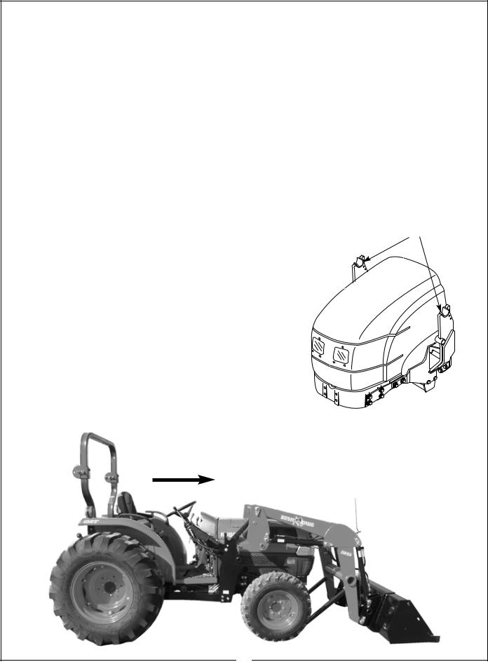
Figure 1-1 Major Components
Bucket Level Indicator Rod
Bucket Cylinder
Cross Tube
Bucket
Subframe
Mainframe Boom
Parking Stands Stored |
Boom Cylinder |
|
1-1 INTRODUCTION
We are pleased to have you as a Bush Hog customer. Your Front End Loader has been carefully designed to give maximum service with minimum down time. This manual is provided to give you the necessary operating and maintenance instructions for keeping your front end loader in top operating condition. Please read this manual thoroughly. Understand what each control is for and how to use it. Observe all safety precautions decaled on the machine and noted throughout the manual for safe operation of implement. If any assistance or additional information is needed, contact your authorized Bush Hog dealer.
1-2 DESCRIPTION
Model 1045 / 2045 / 3045 Front End Loaders are designed for two wheel and four wheel drive tractors. They come equipped with parking stands to support the loader so the tractor can be “driven in” for quick attachment and a bucket level indicator that allows operator to gauge bucket position when the bucket cannot be seen. Available attachments include buckets for lifting loose materials; a bale spear for lifting round hay bales (Model 3045 only); and a fork lift for palletized material (2045 / 32045 Models only). All operations should be conducted within the loader limits specified in Table 1-1.
8
Table 1-1 TECHNICAL SPECIFICATIONS
|
|
VV |
U |
|
V |
D |
|
|
E |
|
|
|
|
XX |
A |
|
|
B |
|
|
J C |
W |
X |
G |
|
ZZ |
F |
|
|
Y |
|
Z |
H |
|
|
|
SERIES LOADER |
1045 |
2045 |
3045 |
|
|
|
|
|
|
|
|
A. Maximum Lift Height - Measured at Pivot Pin |
86 in. |
103 in. |
110 in. |
|
|
|
|
|
|
|
|
B. Maximum Lift Height - Under Level Bucket |
81 in. |
96 in. |
100 in. |
|
|
|
|
|
|
|
|
C. Clearance with Attachment Dumped 45° 92 in. |
67 in. |
77 in. |
82 in. |
|
|
|
|
|
|
|
|
D. Reach at Maximum Height |
23 in. |
22 in. |
30 in. |
|
|
|
|
|
|
|
|
E. |
Maximum Dump Angle |
45° |
40° |
45° |
|
|
|
|
|
|
|
F. Reach with Bucket on Ground |
54 in. |
62 in. |
67 in. |
|
|
|
|
|
|
|
G. |
Maximum Rollback Angle |
25° |
25° |
25° |
|
|
|
|
|
|
|
|
H. |
Digging Depth |
5 in. |
5 in. |
5 in. |
|
|
|
|
|
|
|
J. Overall Height in Carry Position |
48 in. |
56 in. |
56 in. |
|
|
|
|
|
|
|
|
U. Lift Capacity to Maximum Height - At Pivot Pin |
825 lbs. |
1530 lbs. |
2350 lbs. |
|
|
|
|
|
|
|
|
V. Lift Capacity to Maximum Height - 31.5” |
570 lbs. |
880 lbs. |
1500 lbs |
|
|
|
Forward of Pivot Pin |
|
|
|
|
|
|
|
|
|
|
W. Lift Capacity to 59” Height - At Pivot Pin |
940 lbs. |
1730 lbs. |
2700 lbs. |
|
|
|
|
|
|
|
|
X. Lift Capacity to 59” Height - 31.5” |
710 lbs. |
1195 lbs. |
1850 lbs. |
|
|
|
Forward of Pivot Pin |
|
|
|
|
|
|
|
|
|
|
Y. Breakout Force - At Pivot Pin |
1335 lbs. |
2370 lbs. |
4000 lbs. |
|
|
|
|
|
|
|
|
Z. Breakout Force - 31.5” Forward of Pivot Pin |
965 lbs. |
1530 lbs. |
2900 lbs. |
|
|
|
|
|
|
|
|
VV. Rollback Force at Maximum Height - |
1935 lbs. |
1625 lbs. |
2300 lbs. |
|
|
|
31.5” Forward of Pivot Pin |
|
|
|
|
|
|
|
|
|
|
XX. Rollback Force at 59” Height - |
2300 lbs. |
2020 lbs. |
3400 lbs. |
|
|
|
31.5” Forward of Pivot Pin |
|
|
|
|
|
|
|
|
|
|
ZZ. Rollback Force at Ground Level - |
1700 lbs. |
1680 lbs. |
2800 lbs. |
|
|
|
31.5” Forward of Pivot Pin |
|
|
|
|
|
|
|
|
|
|
|
Raising Time - Ground Level to Full Height |
3.5 sec. |
3.8 sec. |
5 sec. |
|
|
|
|
|
|
|
|
Lowering Time - Full Height to Ground |
2.5 sec. |
2.3 sec. |
3 sec. |
|
|
|
|
|
|
|
|
Bucket Dumping Time - Full Rollback |
4.0 sec. |
3.3 sec. |
4 sec. |
|
|
to Full Dump |
|
|
|
|
|
|
|
|
|
|
|
Bucket Rollback Time - Full Dump |
3.0 sec. |
2 sec. |
2.5 sec. |
|
|
to Full Rollback |
|
|
|
|
|
|
|
|
|
|
Tractor HP Range |
15 - 25 |
20 - 40 |
30 - 50 |
|
|
|
|
2 & 4 WD |
2 & 4 WD |
2 & 4 WD |
|
|
|
|
|
|
|
Based On Tractor Hydraulic System: |
|
|
|
|
|
|
Pressure |
1875 psi |
2000 psi |
2500 psi |
|
|
Flow |
6 gpm |
10 gpm |
10 gpm |
|
|
|
|
|
|
9
SECTION II LOADER MOUNTING AND DISMOUNTING
2-1 PREPARING TRACTOR
 CAUTION
TRACTORS THAT HAVE MOVABLE AXLES
MUST BE SET FORWARD IN THE LONG WHEEL-
BASE POSITION AS SHOWN IN FIGURE 2-1 TO
PREVENT EXCESSIVE LEVERAGE BEING
EXERTED ON THE TRACTOR FRAME. FAILURE
TO DO SO CAN RESULT IN PERSONAL INJURY
AND EQUIPMENT DAMAGE. REFER TO TRAC-
TOR OPERATOR’S MANUAL FOR ABOVE PRO-
CEDURES AND SPECIFICATIONS FOR YOUR
TRACTOR.
A.Check air pressure in tractor tires to be sure it is adequate for heavy loads.
B.Add rear wheel weights, fluid in tires, or equivalent to provide sufficient tractor stability.
C.It is recommended that tractor wheels be moved to the widest settings.
D.Check tractor hydraulic oil reservoir to be sure it is full.
E.Refer to your tractor operator’s manual for above procedures and specifications for your tractor.
2-2 MOUNTING LOADER
To aid in mounting and dismounting loader, apply a small amount of grease, if needed, to each loader bracket in area of top receiver and guide. Figure 2-2.
A. Slowly drive tractor to a position where the hoses can be connected to the quick couplers. Stop
the engine. Connect the loader hydraulic hoses to the correct couplers. Figure 2-3.
B. Retract Loader Lift Cylinders. Figure 2-3.
Figure 2-3 Drive In Close Enough To Alllow Connecting
Figure 2-1
Short Wheelbase
Long Wheelbase
Figure 2-2 Apply Grease To These Areas
Hydraulic Hoses To Tractor Outlets
10
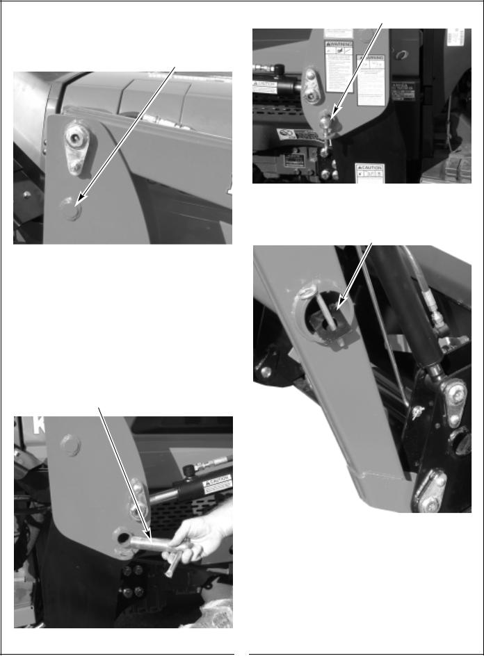
C. Check |
that lift cylinders are fully retracted. |
|
Figure 2-6 |
Pin In Operating Position |
Figure 2-3. Then drive tractor forward. Use bucket |
|
|
|
|
|
|
|
||
cylinders to position height of outer pedestal top pin. |
|
|
|
|
Figure 2-4. |
|
|
|
|
|
|
|
|
|
Figure 2-4 |
Outer Pedestal Top Pin |
|
|
|
|
|
|
|
|
|
|
|
|
|
D. Align outer pedestal top pin with mounting bracket guide post on both sides. Make sure loader
is centered right to left on both brackets.
E.Extend the bucket cylinders to lower the pedestal top pins into mounting bracket receivers on
both sides.
F.Extend lift cylinders slowly making sure loader
is seated completely in mounting bracket top and bottom receivers. Retract bucket cylinder until bucket is approximately 1/2” off ground.
G. Slide quick pin into position and let pin handle extend downward through the retaining loop at the bottom of the subframe. Figures 2-5 and 2-6
Figure 2-5 Quick Pin
H. Remove parking stands from the parked position and return them to their storage positions in the cross tube. Figure 2-7
Figure 2-7 Parking Stand Stored
Secure parking stands in the storage position by using the provided pins.
I. Lower loader to ground and secure loader hydraulic hoses in a protected area.
IMPORTANT
To avoid hydraulic hose damage, be alert and make sure hoses do not catch on tractor and/or loader during mounting or dismounting.
11

2-3 DISMOUNTING LOADER
 CAUTION
ALWAYS PARK LOADER WITH MATERI-
AL BUCKET OR AUTHORIZED BUSH
HOG ATTACHMENT ATTACHED TO THE
LOADER.
 CAUTION
BEFORE LEAVING THE TRACTOR SEAT,
LOWER ATTACHMENT OR LOADER
BOOM TO GROUND, STOP ENGINE,
LOCK BRAKES, RELIEVE HYDRAULIC
PRESSURE, AND REMOVE KEY.
 CAUTION
DO NOT STAND, WALK, OR WORK UNDER
A RAISED LOADER OR ATTACHMENT
UNLESS IT IS SECURELY BLOCKED OR
HELD IN POSITION. ACCIDENTAL MOVE-
MENT OF A CONTROL LEVER/LEVERS OR
LEAKS IN THE HYDRAULIC SYSTEM
COULD CAUSE THE LOADER TO DROP,
OR ATTACHMENT TO DUMP, CAUSING
SEVERE INJURY.
 CAUTION
DO NOT ALLOW BYSTANDERS IN LOADER
AREA.
IMPORTANT
Never allow weight of tractor to be placed on parking stands when mounting or dismounting loader.
A. Position the loader on |
a hard level surface. |
The more level the surface, the |
easier the loader is |
to mount and dismount. |
|
B.Raise loader, dump bucket over, and then lower loader so that bucket cutting edge is approximately 1/2” off of surface.
C.Remove parking stands from their storage positions in the boom crosstube as shown in Figure 2-8.
D. Position parking stands in attaching brackets on inside of each loader arm and secure. Figure 2-9.
E.Dismounting procedures will be the reverse of the mounting procedure.
F.Rollback bucket slightly while lowering loader boom down until the parking stands make firm con-
tact with ground. Dump bucket until bucket touches the surface.
NOTE
Driving the tractor forward slowly while positioning loader will allow parking stands to contact ground firmly.
Figure 2-9 Parking Stands Installed
|
|
|
|
|
|
Long End Positioned Rearward |
Attaching Bracket |
|
|
|
|
G.Retract loader lift cylinders
H.Slowly rollback bucket while driving slightly forward with tractor. Doing this will allow mounting
brackets to guide loader as loader is being parked off of tractor.
I.Rollback bucket completely. Make sure all loader components clear tractor. Stop the tractor engine and then work valve control lever/levers to relieve hydraulic fluid pressure in lines. Refer to tractor operator manual for additional information.
J.Disconnect loader hoses from quick couplers. Start tractor and slowly back tractor away from loader. Figures 2-10, 2-11, 2-12
Figure 2-10 Disconnecting Hydraulic Hoses
12
 Loading...