


BUSH HOG®
Backhoes
BH650 / BH750 / BH850 / BH950
Operator’s Manual
ASSEMBLY • OPERATION • MAINTENANCE
1107 |
$4.00 |
50033052 |

CONGRATULATIONS!
You have invested in the best implement of its type on the market today.
The care you give your Bush Hog implement will greatly determine your satisfaction
with its performance and its service life. We urge a careful study of this manual to provide you with a thorough understanding of your new implement before operating, as well as suggestions for operation and maintenance.
If your manual should become lost or destroyed, Bush Hog will be glad to provide you with a new copy. Order from Bush Hog, P. O. Box 1039, Selma, Alabama 36702-1039.
As an authorized Bush Hog dealer, we stock genuine Bush Hog parts which are manufactured with the same precision and skill as our original equipment. Our trained service personnel are well informed on methods required to service Bush Hog equipment, and are ready and able to help you.
Should you require additional information or assistance, please contact us.
YOUR AUTHORIZED
BUSH HOG DEALER
BECAUSE BUSH HOG MAINTAINS AN ONGOING
PROGRAM OF PRODUCT IMPROVEMENT, WE
RESERVE THE RIGHT TO MAKE IMPROVEMENTS IN
DESIGN OR CHANGES IN SPECIFICATIONS WITH-
OUT INCURRING ANY OBLIGATION TO INSTALL
THEM ON UNITS PREVIOUSLY SOLD.
BECAUSE OF THE POSSIBILITY THAT SOME
PHOTOGRAPHS IN THIS MANUAL WERE TAKEN OF
PROTOTYPE MODELS, PRODUCTION MODELS MAY
VARY IN SOME DETAIL. IN ADDITION, SOME
PHOTOGRAPHS MAY SHOW SHIELDS REMOVED
FOR PURPOSES OF CLARITY. NEVER OPERATE
THIS IMPLEMENT WITHOUT ALL SHIELDS IN PLACE.

BACKHOES
Operator’s Manual
TABLE OF CONTENTS
SECTION/PARA |
PAGE |
|
SECTION/PARA |
PAGE |
Warranty . . . . . . . . . . . . . . . . . . . . . . . . . |
. . . . . 2 |
|
Tooth Replacement |
15 |
Dealer Preparation Check List. . . . . . . . . |
. . . . . 3 |
|
Lubrication |
15 |
Safety Procedures . . . . . . . . . . . . . . . . . . |
. . . . . 5 |
|
Removal / Storage |
16 |
Federal Laws and Regulations . . . . . . . . |
. . . . . 7 |
|
Stabilizer Pads |
17 |
General Operation . . . . . . . . . . . . . . . . . . |
. . . . . 8 |
|
Hydraulic Trouble Shooting |
17 |
Controls . . . . . . . . . . . . . . . . . . . . . . . . . . |
. . . . . 8 |
|
Valve Repair |
23 |
Operating The Backhoe. . . . . . . . . . . . . . |
. . . . . 9 |
|
Assembly |
24 |
Transporting The Backhoe . . . . . . . . . . . |
. . . . 10 |
|
Mounting Kit Instructions |
25 |
Placing The Stabilizers . . . . . . . . . . . . . . |
. . . . 11 |
|
PTO Pump Kits |
30 |
Filling The Bucket . . . . . . . . . . . . . . . . . . |
. . . . 12 |
|
Hydraulic Hook-Up To Tractor |
31 |
Dumping The Bucket . . . . . . . . . . . . . . . . |
. . . . 12 |
|
Power Beyond Kit |
35 |
Trenching. . . . . . . . . . . . . . . . . . . . . . . . . |
. . . . 12 |
|
Flow Divider Kit |
38 |
Back Filling . . . . . . . . . . . . . . . . . . . . . . . |
. . . . 13 |
|
General Specifications |
42 |
Service. . . . . . . . . . . . . . . . . . . . . . . . . . . |
. . . . 14 |
|
Removing From Shipping Pallet |
43 |
Beginning Of Season. . . . . . . . . . . . . . . . |
. . . . 14 |
|
Safety Decals |
44 |
Hydraulic System. . . . . . . . . . . . . . . . . . . |
. . . . 14 |
|
Torque Specifications |
45 |
|
|
|
|
|
|
|
|
|
|
|
|
|
|
|
|
|
|
|
|
RETAIL CUSTOMER’S RESPONSIBILITY
UNDER THE BUSH HOG WARRANTY
It is th e R etail C u sto m er an d /o r O p erato r’s resp o n sib ility to read th e O p erato r’s M an u al, to o p erate, lu b ricate, m ain tain , an d sto re th e p ro d u ct in acco rd an ce w ith all in stru ctio n s an d safety p ro ced u res . F ailu re o f th e o p erato r to read th e O p erato r’s M an u al is a m isu se o f th is eq u ip m en t.
It is th e R etail C u sto m er an d /o r O p erato r’s resp o n sib ility to in sp ect th e p ro d u ct an d to h ave an y p art(s) rep aired o r rep laced w h en co n tin u ed o p eratio n w o u ld cau se d am ag e o r exces - sive w ear to o th er p arts o r cau se a safety h azard .
It is th e R etail C u sto m er’s resp o n sib ility to d eliver th e p ro d u ct to th e au th o rized B u sh H o g d ealer fro m w h o m h e p u rch ased it, fo r service o r rep lacem en t o f d efective p arts w h ich are co vered b y w arran ty . R ep airs to b e su b m itted fo r w arran ty co n sid eratio n m u st b e m ad e
w ith in fo rty -five (45) d ays o f failu re .
It is th e R etail C u sto m er’s resp o n sib ility fo r an y co st in cu rred b y th e D ealer fo r travelin g to o r h au lin g o f th e p ro d u ct fo r th e p u rp o se o f p erfo rm in g a w arran ty o b lig atio n o r in sp ectio n .
1

LIMITED WARRANTY
OOOOOOOOOOOOOOOOOOOOOOOOOOOOOOO
Bush Hog warrants to the original purchaser of any new Bush Hog equipment, purchased from an authorized Bush Hog dealer, that the equipment be free from defects in material and workmanship for a period of one (1) year for non-commercial, state, and municipalities’ use and ninety (90) days for commercial use from date of retail sale. The obligation of Bush Hog to the purchaser under this warranty is limited to the repair or replacement of defective parts.
Replacement or repair parts installed in the equipment covered by this limited warranty are warranted for ninety (90) days from the date of purchase of such part or to the expiration of the applicable new equipment warranty period, whichever occurs later. Warranted parts shall be provided at no cost to the user at an authorized Bush Hog dealer during regular working hours. Bush Hog reserves the right to inspect any equipment or parts which are claimed to have been defective in material or workmanship.
DISCLAIMER OF IMPLIED WARRANTIES & CONSEQUENTIAL DAMAGES
Bush Hog’s obligation under this limited warranty, to the extent allowed by law, is in lieu of all warranties, implied or expressed, INCLUDING IMPLIED WARRANTIES OF MERCHANTABILITY AND FITNESS FOR A PARTICULAR PURPOSE and any liability for incidental and consequential damages with respect to the sale or use of the items warranted. Such incidental and consequential damages shall include but not be limited to: transportation charges other than normal freight charges; cost of installation other than cost approved by Bush Hog; duty; taxes; charges for normal service or adjustment; loss of crops or any other loss of income; rental of substitute equipment, expenses due to loss, damage, detention or delay in the delivery of equipment or parts resulting from acts beyond the control of Bush Hog.
THIS LIMITED WARRANTY SHALL NOT APPLY:
1.To vendor items which carry their own warranties, such as engines, tires, and tubes.
2.If the unit has been subjected to misapplication, abuse, misuse, negligence, fire or other accident.
3.If parts not made or supplied by Bush Hog have been used in connection with the unit, if, in the sole judgement of Bush Hog such use affects its performance, stability or reliability.
4.If the unit has been altered or repaired outside of an authorized Bush Hog dealership in a manner which, in the sole judgement of Bush Hog, affects its performance, stability or reliability.
5.To normal maintenance service and normal replacement items such as gearbox lubricant, hydraulic fluid, worn blades, or to normal deterioration of such things as belts and exterior finish due to use or exposure.
6.To expendable or wear items such as teeth, chains, sprockets, belts, springs and any other items that in the company’s sole judgement is a wear item.
NO EMPLOYEE OR REPRESENTATIVE OF BUSH HOG IS AUTHORIZED TO CHANGE THIS LIMITED WARRANTY IN ANY WAY OR GRANT ANY OTHER WARRANTY UNLESS SUCH CHANGE IS MADE IN WRITING AND SIGNED BY BUSH HOG’S SERVICE MANAGER, POST OFFICE BOX 1039, SELMA, ALABAMA 36702-1039.
OOOOOOOOOOOOOOOOOOOOOOOOOOOOOOO
Record the model number, serial number and date
purchased. This information will be helpful to your MODEL NUMBER dealer if parts or service are required.
MAKE CERTAIN THE WARRANTY REGISTRATION |
SERIAL NUMBER |
|
|
|
|
||
CARD HAS BEEN FILED WITH BUSH HOG/ |
|
|
|
SELMA, ALABAMA |
DATE OF RETAIL SALE |
|
|
2

DEALER PREPARATION CHECK LIST
BH650 - BH750 - BH850 - BH950 BACKHOES
BEFORE DELIVERING MACHINE - The following check list should be completed. Use the Operator’s Manual as a guide.
qMachine properly assembled.
qAll safety decals readable (See decal page).
qAll bolts tightened to torque specifications given in the torque chart.
qMachine operates properly.
qOperator’s manual has been delivered to owner and he has been instructed on the safe and proper use of the backhoe.
Dealer’s Signature
 CAUTION:
It is recommended that the tractor be equipped with Rollover Protection System (ROPS) and seat belt be used for all implement operations.
.
THIS CHECKLIST TO REMAIN IN OWNER’S MANUAL
It is the responsibility of the dealer to complete the procedures listed above before delivery of this implement to the customer.
3

Safety Alert Symbol
This Safety Alert Symbol means: “ATTENTION! BECOME ALERT!
YOUR SAFETY IS INVOLVED!”
This symbol is used to call attention to safety precautions that should be followed by the operator to avoid accidents. When you see this symbol, carefully read the message that follows and heed its advice. Failure to comply with safety precautions could result in death or serious bodily injury.
Safety Signs Signal Words
The signal words DANGER, WARNING, AND CAUTION are used on the equipment safety signs. These words are intended to alert the viewer to the existence and the degree of hazard seriousness.
This signal word indicates a potentially hazardous situation which, if not avoided, will result in death or serious injury.
White letters on RED
This signal word indicates a potentially hazardous situation which, if not avoided, could result in death or serious injury
It may also be used to alert against unsafe practices.
Black letters on ORANGE
This signal word indicates a potentially hazardous situation exist which, if not avoided, may result in minor or moderate injury.
It may also be used to alert against unsafe practices.
Black letters on YELLOW
4

IMPORTANT SAFETY PRECAUTIONS
This symbol is used to call attention to safety precautions that should be followed by the operator to avoid accidents. When you see this symbol, carefully read the message that follows and heed its advice. Failure to comply with safety precautions could result in serious bodily injury.
In addition to the design and configuration of equipment, hazard control and accident prevention are dependent upon the awareness, concern, prudence and proper training of personnel in the operation, transport, maintenance and storage of equipment. Lack of attention to safety can result in accident, personal injury, reduction of efficiency and worst of all—loss of life. Watch for safety hazards and correct deficiencies promptly. Use the following safety precautions as a general guide to safe operations when using this machine. Additional safety precautions are used throughout this manual for specific operating and maintenance procedures. Read this manual and review the safety precautions often until you know the limitations.
THE TRACTOR
1.Read the tractor operator’s manual to learn how to operate your tractor safely. Failure to do so could result in serious injury or death and equipment damage.
2.It is recommended that tractor be equipped with Rollover Protective System (ROPS) and a seat belt be used for all loader operations.
3.Add wheel ballast or front weight for stability.
4.Move wheels to the tractor manufacturer’s widest recommended settings to increase stability.
5.For better stability, use tractor with wide front axle rather than tricycle front wheels.
6.Move and turn the tractor at low speeds.
7.Stop tractor engine, place transmission in park (or neutral), engage parking brake, lower loader arms to ground, cycle all hydraulic controls to relieve pressure, allow machine moving parts to stop, remove ignition key to prevent unauthorized person from starting engine before dismounting tractor or servicing, repairing, or making adjustments to the equipment.
8.Wear personal protective equipment (PPE) such as, but not limited to, protection for eyes, ears, lungs, head, hands and feet when operating, servicing, or repairing equipment. Avoid wearing loose clothing or jewelry that may catch and entangle on equipment moving parts.
THE BACKHOE
1.DO NOT operate the backhoe unless it is rigidly attached to the tractor or skid steer loader.
2.KNOW your controls. Read this operator’s manual and the manual provided with your tractor. Learn how to stop the tractor, the engine and the backhoe quickly in an emergency.
3.PROVIDE adequate front end weight to counter-balance the backhoe at all times. 20% of the total tractor, loader and backhoe weight must be on the tractor front axle. If unsure of weight distribution, determine at a weight scale. Total vehicle weight , including backhoe and counter weights, must not exceed the ROPS certificate for gross vehicle weight.
4.BE SURE the area is clear of overhead or underground utilities or other hazards.
5.POSITION a barricade around the work area.
6.KEEP all bystanders a safe distance away.
7.DO NOT attempt to enter operator’s platform of backhoe by using the stabilizers as a step.
8.OPERATE from the backhoe operator’s seat only.
9.ALLOW only one person to operate the backhoe at any time.
10.DISENGAGE safety locks as shown in Figures 1 & 3 before attempting to operate the backhoe.
11.NEVER dig with the backhoe unless the stabilizers are properly set.
5

SAFETY PRECAUTIONS CONTINUED
12.DO NOT dig under stabilizers or tractor backhoe. Soft ground or sandy soil can cause cave-ins.
13.KEEP BUCKET away from the stabilizer area to avoid possible stabilizer damage.
14.ALWAYS swing bucket uphill to dump when on a hillside and keep loaded bucket low.
15.SET BRAKES and block wheels when operating on hills and banks to avoid dangerous runaway.
16.WATCH for overhead wires. DO NOT touch wires with any part of the backhoe.
17.NEVER allow a person to work under a raised bucket.
18.NEVER lift a person with the backhoe.
19.DO NOT use the backhoe as a battering ram. Use the backhoe only for digging.
20.ALWAYS lower the backhoe bucket and stabilizers to the ground, shut off engine, and apply the parking brake before getting off unit, or when not digging.
21.NEVER leave the tractor unattended with the engine running.
22.DO NOT attempt to raise the tractor off the ground or move the tractor forward or backward using the backhoe dipperstick or bucket.
TRANSPORTATION
1.ALWAYS engage safety locks before transporting backhoe. See Figures 1 & 3.
2.DO NOT drive the tractor near the edge of a ditch or excavation.
3.ALWAYS use accessory lights and devices when transporting on a road or highway to warn operators of other vehicles. Check your local government regulations.
4.BE SURE the SMV emblem is visible to the rear.
ADJUSTMENTS AND INSPECTION
1.CHECK pins that attach backhoe to tractor and all pivot pins for tightness several times daily. Replace any parts that are bent, broken or missing.
2.ALWAYS engage safety locks before servicing backhoe. See Figures 1 & 3.
3.DO NOT oil, grease, or adjust the backhoe while it is in motion. For greasing, see Service section for details.
4.DO NOT change any backhoe relief valve settings. They are factory set for best backhoe performance and safety.
5.PROTECT YOUR EYES - WEAR SAFETY GLASSES.
6.GUARD AGAINST INJURY when driving connecting pins or performing any repair in which particles can chip from work piece or striking tool.
7.DO NOT remove any guards on backhoe or tractor.
AVOID HIGH-PRESSURE FLUIDS
ESCAPING fluid under pressure can have sufficient force to penetrate the skin and cause serious injury. Be sure to stop engine and relieve all pressure before disconnecting lines. Be sure all connections are tight and that lines, pipes, and hoses are not damaged before applying pressure to the system. Fluid escaping from a very small hole can be almost invisible. Use a piece of cardboard or wood - not your hands-to search for suspected leaks.
SEE A DOCTOR at once if injured by escaping fluid. Serious infection or gangrene can develop if proper medical treatment is not administered immediately.
6

IMPORTANT FEDERAL LAWS AND REGULATIONS* CONCERNING
EMPLOYERS, EMPLOYEES AND OPERATIONS.
*(This section is intended to explain in broad terms the concept and effect of the following federal laws and regulations. It is not intended as a legal interpretation of the laws and should not be considered as such).
U.S. Public Law 91-596 (The Williams-Steiger Occupational Safety and Health Act of 1970) OSHA
This Act Seeks:
“...to assure so far as possible every working man and woman in the nation safe and healthful working conditions and to preserve our human resources...”
DUTIES
Sec. 5 (a) Each employer—
(1)shall furnish to each of his employees employment and a place of employment which are free from recognized hazards that are causing or are likely to cause death or serious physical harm to his employees;
(2)shall comply with occupational safety and health standards promulgated under this Act.
(b)Each employee shall comply with occupational safety and health standards and all rules, regulations and orders issued pursuant to this Act which are applicable to his own actions and conduct.
OSHA Regulations
Current OSHA regulations state in part: “At the time of initial assignment and at least annually thereafter, the employer shall instruct every employee in the safe operation and servicing of all equipment with which the employee is, or will be involved.” These will include (but are not limited to) instructions to:
Keep all guards in place when the machine is in operation;
Permit no riders on equipment;
Stop engine, disconnect the power source, and wait for all machine movement to stop before servicing, adjusting, cleaning or unclogging the equipment, except where the machine must be running to be properly serviced or maintained, in which case the employer shall instruct employees as to all steps and procedures which are necessary to safely service or maintain the equipment.
Make sure everyone is clear of machinery before starting the engine, engaging power, or operating the machine.
EMPLOYEE TRACTOR OPERATING INSTRUCTIONS:
1.Securely fasten your seat belt if the tractor has a ROPS.
2.Where possible, avoid operating the tractor near ditches, embankments, and holes.
3.Reduce speed when turning, crossing slopes, and on rough, slick, or muddy surfaces.
4.Stay off slopes too steep for safe operation.
Child Labor Under 16 Years Old
5.Watch where you are going, especially at row ends, on roads, and around trees.
6.Do not permit others to ride.
7.Operate the tractor smoothly - no jerky turns, starts, or stops.
8.Hitch only to the drawbar and hitch points recommended by tractor manufacturers.
9.When tractor is stopped, set brakes securely and use park lock if available.
Some regulations specify that no one under the age of 16 may operate power machinery. It is your responsibility to know what these regulations are in your own area or situation. (Refer to U.S. Dept. of Labor, Employment Standard Administration, Wage & Home Division, Child Labor Bulletin #102.)
7
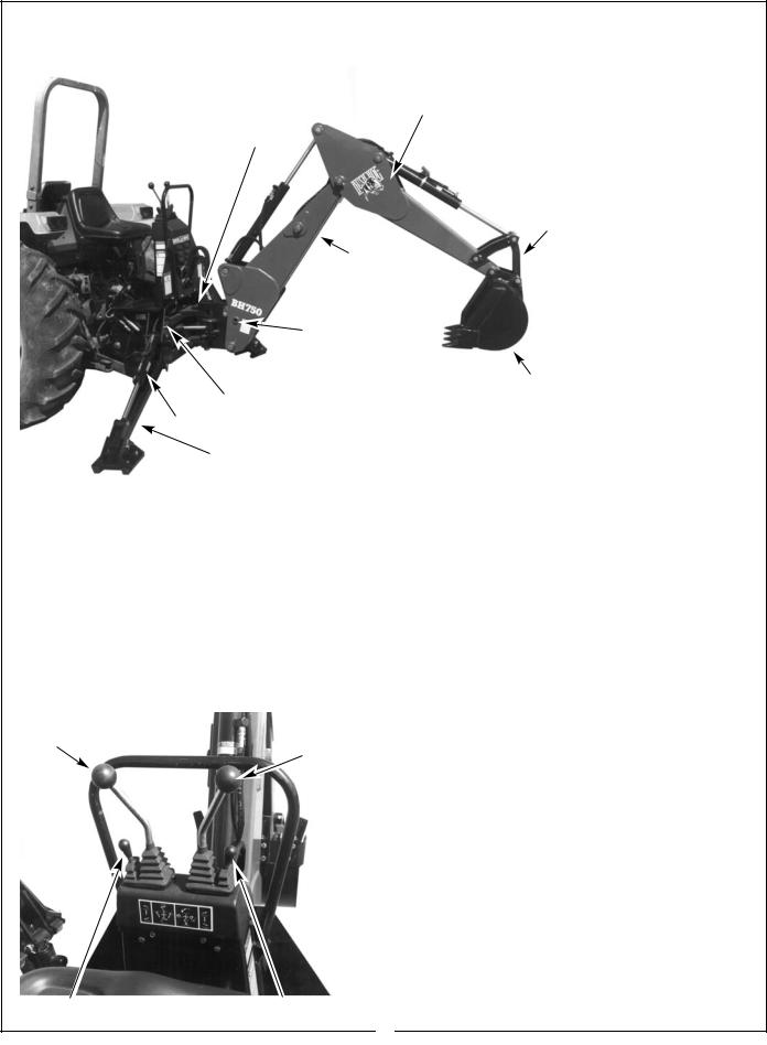
GENERAL OPERATION
Figure 1
Dipper-Stick
Swing
Lock Pin Location
Bucket
Link
Boom
Boom Transport
Lock Pin Location
Bucket
Mainframe
Stabilizer Cylinder
Stabilizer
 CAUTION
T o a v o i d p o s s i b l e i n j u r y , o b s e r v e t h e fo llo w in g safety ru les B E F O R E O P E R A T IN G th e b ackh o e:
1 . B E S U R E a r e a i s c le a r o f u n d e rg ro u n d u tilitie s o r o th e r h a z - ard s .
2 . P O S I T I O N b a r r i - c a d e a r o u n d w o r k area .
3 . P R O V ID E ad eq u ate f r o n t e n d w e i g h t t o
c o u n te r-b a la n c e |
tra c - |
to r a t a ll tim e s . |
2 0 % |
o f t h e t o t a l t r a c t o r , lo a d e r a n d b a c k h o e w e i g h t m u s t b e o n th e tracto r fro n t axle . 4 . K eep b ystan d ers a safe d istan ce aw ay .
DIRECTIONS: The terms right, left, front and back shall be determined from the position of the operator when seated in the operating position on the backhoe.
Engine Speed
The speed at which the backhoe operates is partially dependent on engine RPM. Use a moderate engine speed to start and increase it as your experience permits. Refer to “SPECIFICATIONS” for hydraulic flow volume requirements. When powering from tractor systems with higher output, reduce engine RPM to obtain acceptable backhoe operating speed.
Figure 2 |
Control Handles |
|
|
|
|
BOOM & |
||
SWING |
|
CROWD & |
|
|
BUCKET |
Left Hand Stabilizer |
Right Hand Stabilizer |
CONTROLS
The backhoe has two major control levers plus the stabilizer control levers. These controls are located on the control console directly ahead of the operator. See Figure 2. The following is a list of the controls, with the function of each, reading from left to right.
1.Left Hand Stabilizer: Push lever forward, the LH stabilizer lowers. Pull lever back, the LH stabilizer raises.
2.Boom/Swing: Push lever forward, the boom moves down, away from the operator. Pull lever back, the boom moves up, toward the operator.
The Boom/Swing Control Lever has an added “float” function. A detent or stop should be felt when the lever is pushed forward to move the boom down. Pushing the lever forward more will overcome the detent and cause the boom to float, or move down or up freely, depending on the forces acting on it. When the lever is released it should return to the center, neutral position.
Move lever to the left, the backhoe swings to the left. Move lever to the right, the backhoe swings to the right.
By moving the lever to one of the intermediate positions, the boom can be swung left or right at the same time it is being raised or lowered, performing the two operations simultaneously.
SWING LEFT AND LOWER the boom by moving the control lever forward and to the left.
8
Figure 3 Safety Locks
|
|
|
|
|
|
|
|
Swing Lock Pin |
|
Boom Transport Lock Pin |
|
|
|
|
|
SWING LEFT AND RAISE the boom by moving the control lever back and to the left.
SWING RIGHT AND LOWER the boom by moving the lever forward and to the right.
SWING RIGHT AND RAISE the boom by moving the lever back and to the right.
3. Crowd/Bucket: Push lever forward, the dipperstick moves out, away from the operator. Pull lever back, the dipperstick moves in, toward the operator.
Move lever to left, the bucket curls in. Move lever to right, the bucket extends out.
By moving the lever to one of the intermediate positions, the dipperstick can be extended or retracted at the same time the bucket is being loaded or dumped.
EXTEND AND LOAD the bucket by moving the lever forward and to the left.
RETRACT AND LOAD the bucket by moving the lever back and to the left.
EXTEND AND DUMP the bucket by moving the lever forward and to the right.
RETRACT AND DUMP the bucket by moving the lever back and to the right.
The two operations of the boom/swing lever, combined with the two operations performed by the crowd/bucket control lever, provide four simultaneous operations from the two levers, keeping cycle time to a minimum.
4. Right Hand Stabilizer: Push lever forward, the RH stabilizer lowers. Pull lever back, the RH stabilizer raises.
Figure 3a
Lock Pins
Storage Tubes
In general, the direction of movement of a control lever corresponds to the movement of the operating member.
OPERATING THE BACKHOE
 CAUTION
To avoid possible injury, observe the following safety rules WHEN OPERATING the backhoe.
1.DISENGAGE safety lock pins as shown in Figure 3 before attempting to operate the backhoe. Store lock pins in angled tubes located at the rear right hand side of the backhoe below the foot platform. See Figure 3a.
2.OPERATE from the backhoe operator’s seat only.
3.LOWER the stabilizers until the rear of the tractor is totally supported by them. NOTE: Rear tires should not come up off of the ground. See diagram on Page 11.
4.DO NOT dig near the stabilizers.
5.DO NOT touch overhead wires with any part of the backhoe.
6.DO NOT attempt to raise the tractor off the ground or move the tractor forward or backward using the backhoe dipperstick or bucket.
7.DO NOT lose stability by swinging the bucket downhill when positioned on a slope.
8.DO NOT lower the backhoe boom using the “float” function. It will freefall, and could result in injury to bystanders or damage to the backhoe.
9

Location: Back Of Control Panel
It is not difficult to become an efficient operator. Control lever operating decal is located on back of the control console. Study this decal. It will assist you in becoming familiar with the controls.
Smooth, light handling of the controls will result in the most efficient backhoe operation.
Operate the backhoe control levers to become familiar with their speed and movements. The engine speed and the size of the hydraulic system will determine the speed of cylinder operation. When powering from tractor systems with higher output than required, reduce engine RPM to obtain acceptable backhoe operating speed. If backhoe is to be mounted to a tractor or to a skid steer loader with a hydraulic flow rate exceeding 12 gallons per minute (gpm), then the backhoe must be equipped with a Flow Divider Kit. Refer to “Flow Divider Kit” section of this manual for assembly and installation instructions.
Swing the boom several times to practice controlling the speed of swing. Do not operate the swing more than 45° each way for the first few times, then gradually increase the arc.
IMPORTANT: To avoid damage to the backhoe, do not slam unit into the rubber bumpers when swinging the boom right or left.
The boom “float” function may be used during digging to eliminate down pressure when cleaning the bottom of a trench. The primary purpose of the boom “float” function is to protect the operator from serious injury in the event that the backhoe or tractor hitch would
Best results are obtained by digging near the center of the swing arc so material can be dumped on either side.
As the operator becomes more familiar with the operation of the backhoe, it will be common practice to operate two controls at one time. For example, with the bucket extended and the dipperstick extended, the lift control and crowd control can be operated together to bring the bucket toward the operator with down pressure on it. As the dipperstick approaches the operator, the crowd and bucket controls can be operated to close the bucket and trap the material. At the end of the stroke, the lift and crowd controls are operated to move the load up and away from the
operator to save time in clearing the excavation.
This dual operation of controls will speed and simplify the digging operation. Normally the two or more movements will not be equal or even simultaneous, but as the pressure within the cylinders changes, and the resistance on an operating member of the hoe lessens, it will begin to move. It is balancing the force of one member against the other.
NOTE: Actuating the bucket is the key to powerful digging. Operating the crowd and bucket controls simultaneously will insure a full bucket and prevent waste motion and time.
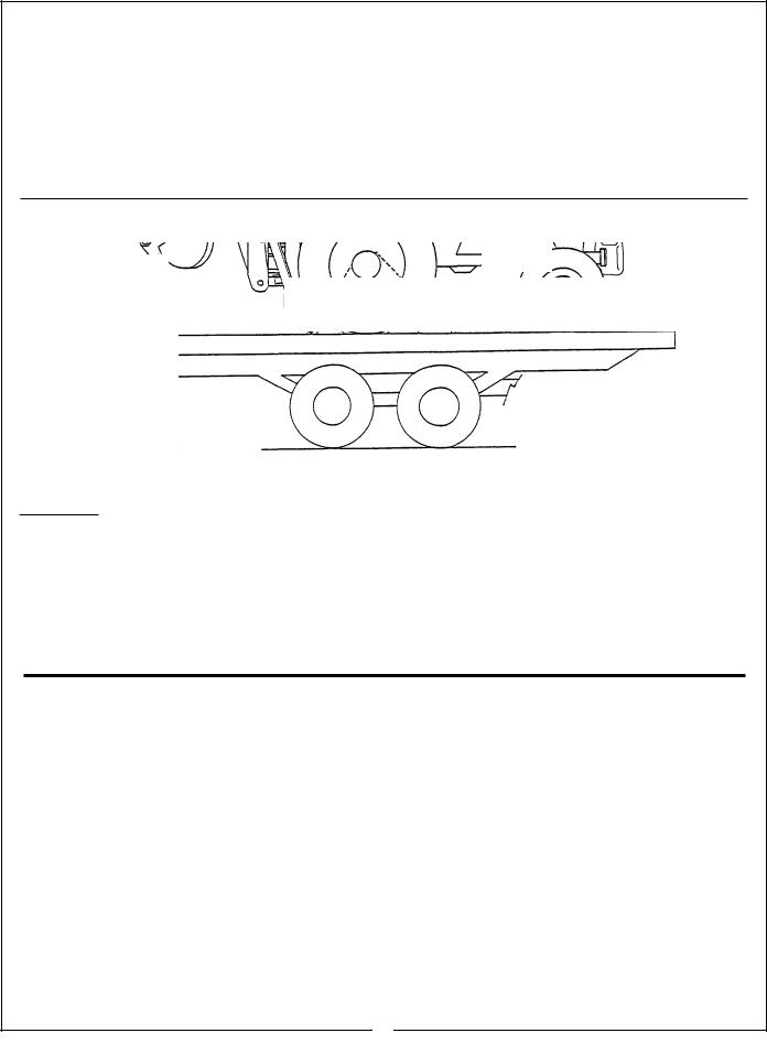
TRANSPORTING THE BACKHOE
IMPORTANT: To prevent serious damage to the tractor, read and follow the instructions on the following decal:
IMPORTANT
IMPROPER TRANSPORTING
METHODS CAN CAUSE SER-
IOUS DAMAGE TO TRACTOR.
•ENGAGE BOTH SAFETY LOCKS WHEN TRANSPORTING BACKHOE.
•TRAVEL SLOWLY OVER ROUGH TERRAIN.
•WHEN TRANSPORTING ON TRUCK OR TRAILER, LOWER BACKHOE BOOM SO BUCKET RESTS FIRMLY ON BED. APPLY RESTRAINTS TO TRACTOR, NOT TO BACKHOE OR BACKHOE ATTACHING KIT.
50102295
Location: Right Side of Boom
10
 CAUTION
To avoid possible injury, observe the following safety rules when transporting the backhoe:
1.ALWAYS engage safety locks as shown on Figs. 1 and 3 when transporting backhoe.
2.TRAVEL SLOWLY over rough terrain, on hillsides, and around curves to prevent tipping.
3.DO NOT drive the tractor near the edge of a ditch or excavation.
4. USE accessory lights and SMV emblem when traveling on highways.
Before leaving backhoe operator’s seat, position the backhoe for transport by raising boom, crowding dipperstick in, swinging to center and raising the stabilizers.
When transporting for long distances, periodically examine the backhoe and raise stabilizers and bucket back up to the full transport height. It is normal for the backhoe to slowly settle while being transported.
WHEN TRANSPORTING
Figure 4
Note: Bucket should be lowered to bed when possible.
DO NOT attach hold down chains anywhere on backhoe assembly.
 CAUTION
DO NOT CHAIN BACKHOE DOWN IN ORDER TO SECURE TRACTOR TO TRAILER
Block and secure tractor only.
PLACING THE STABILIZERS
Decreased
Digging
Depth
|
|
Narrower |
|
|
|
|
Stabilizer |
|
|
|
|
|
Stabilizers Improperly Positioned |
|
Stabilizers Properly Positioned |
|
|
||
|
Platform |
|
||
|
|
|
|
|
|
|
|
|
|
|
|
|
|
|
Set the stabilizers to remove weight from the rear wheels. The wheels are to remain touching the ground as this provides for the widest stabilizer stance and the lowest center of gravity. Raising the wheels off the ground will not only reduce stability and digging depth, but will impair performance and impose unnecessary stress on the unit.
11

General Operations
FILLING THE BUCKET
Control the bucket attitude throughout the digging cycle to keep teeth at the proper angle for best penetration. This will minimize dragging and scraping the bucket through the ground.
When digging in hard-packed soil, bucket penetration can be increased by applying down pressure with the boom while crowding in and curling the bucket. If the crowd action “stalls” it may be necessary to apply lift occasionally during the digging cycle to correct the bucket depth.
To obtain a cleaner trench and avoid the buildup of material directly in front of the backhoe, crowd out and completely curl the bucket while starting to lift it from the excavation. In this way, excess material will fall back into the excavation.
DUMPING THE BUCKET
To dump the bucket at the end of the digging cycle, lift the bucket clear of the trench while crowding it out and swinging it to the spoil pile.
As the pile is approached, dump the bucket. When the bucket is empty, the dipperstick and bucket are in position to resume digging upon return to the trench.
IMPORTANT: Avoid constant jarring or hammering-type contact between the spoil pile and the loaded bucket, as this may cause premature wear to the backhoe pins and bushings.
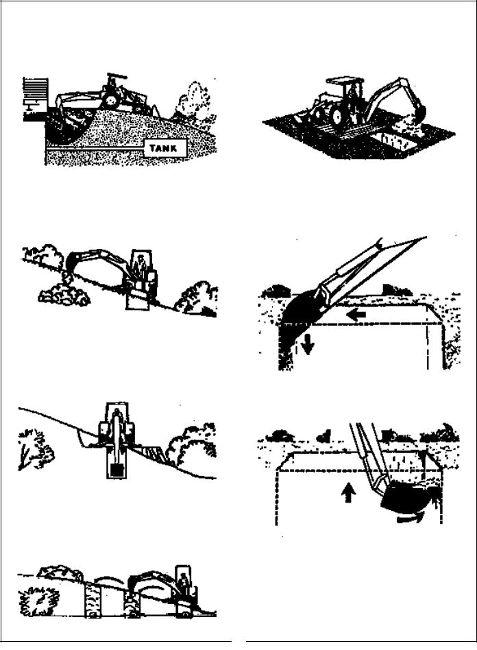
TRENCHING BETWEEN A BUILDING AND OPEN EXCAVATIONS
Start the trench at the building. Trench out halfway to the excavation. Then start trenching from the excavation to the first trench. Dig toward the first trench until there is just enough room to move the unit out between the two trenches.
Position the unit so the backhoe swing post is over the centerline of the trench connection. Dig with the backhoe at extreme swing positions, and in as close to the stabilizers as possible. Pile the spoil on the opposite side of the trenches.
Position the unit forward with the lift and crowd levers so the two trenches can be connected. Pile the spoil on the opposite side of the trench.
12
General Operations
SIDE SLOPE EXCAVATING OR TRENCHING
Dig with the backhoe uphill whenever possible.
Level the backhoe on slopes with the stabilizers to dig plumb trenches, or use the backhoe or loader to cut a level slot for the uphill wheel and stabilizer. Pile the spoil from the slot on the low side.
When on the side of a steep slope, cut a level surface along the uphill side of the trench with the loader.
Pile the spoil of the cut downhill. When digging, pile the spoil of the trench uphill.
Dig field trenches progressively. As soon as one trench is completed, have the workmen lay the tile. Start the next trench, using the spoil to fill the previous trench.
MISCELLANEOUS
When finishing straight walls or bellholes in sandy soil, use a platform under the rear tires and the stabilizers. The platform distributes the load over a larger area and lessens the possibility of a cave-in. The platform also tends to keep the unit from creeping rearward if hard digging is encountered.
FINISHING STRAIGHT WALLS
Finish the far wall by crowding out while forcing the bucket down from the boom. Actuate the bucket (curl out) to keep the bottom of the bucket vertical.
To finish the near wall, lift up and crowd in. Keep the edges of the bucket horizontal.
BACKFILLING
Backfill by lifting the bucket over the spoil pile and then crowding in. Pull both the crowd and lift levers for smooth, even backfilling.
IMPORTANT: Do not backfill by using the swing circuit and dragging the bucket sideways. Doing so can cause damage to the dipperstick, boom, or swing cylinders and/or the mainframe.
13
 Loading...