

Page 1
Page 2

2
CONTENTS
Installation...................................................3
DIN Front-Mount (Method A)
.....................
3
Installing the unit.......................................... 3
Removing the unit........................................4
DIN Rear-Mount (Method B)
......................
5
Using the detachable front panel..........6
Wiring Connection.................................... 7
ISO connection
.............................................
7
Location of keys........................................ 8
Basic operation.......................................... 9
Switching on/off the unit
.............................
9
Faceplate release........................................ 9
Sound adjustment........................................9
Loudness
.......................................................
9
Display...........................................................9
Equalization.................................................. 9
Reset function
..............................................
9
Mode selection............................................. 9
System setting..............................................9
Auxiliary input
...............................................
10
Radio operation......................................... 10
Selecting the frequency band.................... 10
Selecting a station
.......................................
10
Automatic memory storing & program
scanning........................................................ 10
Station storing
..............................................
10
RDS............................................................... 10
Setting RDS mode
.......................................
10
Using PTY to select program
.....................
10
TA SEEK/ALARM.........................................11
PI SOUND/MUTE........................................ 11
RETURN LONG/SHORY........................... 11
MASK DIP/ALL.......................................... 12
EONTA DX/LO........................................... 12
TA-VOLUME
..............................................
12
REG OFF/ON.............................................12
EONTA DX/LO........................................... 12
Listening to Traffic Announcement
.........
12
DAB operation..........................................13
CD(MP3/WMA) operation...................... 13
Switching to CD mode
..............................
13
Selecting tracks......................................... 13
Pausing playing......................................... 13
Previewing all tracks
.................................
13
Repeating the same track........................ 13
Playing all tracks in random.....................14
Ejecting a disc............................................14
Disc notes...................................................15
USB play operation
.................................
16
SD/MMC operation..
................................
16
Bluetooth operation................................16
Preparing for operation.............................16
Pairing
.........................................................
16
Connect.......................................................17
T-menu
........................................................
17
Making an outgoing call
...........................
18
Transfer the call between mobile phone
and the unit.................................................18
BT reset...................................................... 18
Bluetooth audio (A2DP function)............ 18
Specification
.............................................
19
Trouble shooting
.....................................
20
Page 3
3
INSTALLATION
Notes:
Choose a mounting location where the
unit will not interfere with the normal
driving function of the driver.
Before finally installing the unit,
connect the wiring temporarily, and
make sure it is all connected up
properly and the unit and the system
work correctly.
Use only the parts included with the
unit to ensure proper installation. The
use of unauthorized parts can cause
malfunctions.
Consult with your nearest dealer if
installation requires the drilling of holes
or other modifications of the vehicle.
Install the unit where it does not get in
the driver’s way and cannot injure the
passenger if there is a sudden stop,
like an emergency stop.
If installation angle exceeds 30°from
horizontal, the unit might not give its
optimum performance.
Avoid installing the unit where it would
be subject to high temperatures, such
as from direct sunlight, or from hot air,
from the heater, or where it would be
subject to dust, dirt or excessive
vibration.
DIN FRONT/REAR-MOUNT
This unit can be properly installed either
from “Front” (conventional DIN
Front-mount) or “Rear” (DIN
Rear-mount installation, utilizing
threaded screw holes at the sides of the
unit chassis). For details, refer to the
following illustrated installation
methods.
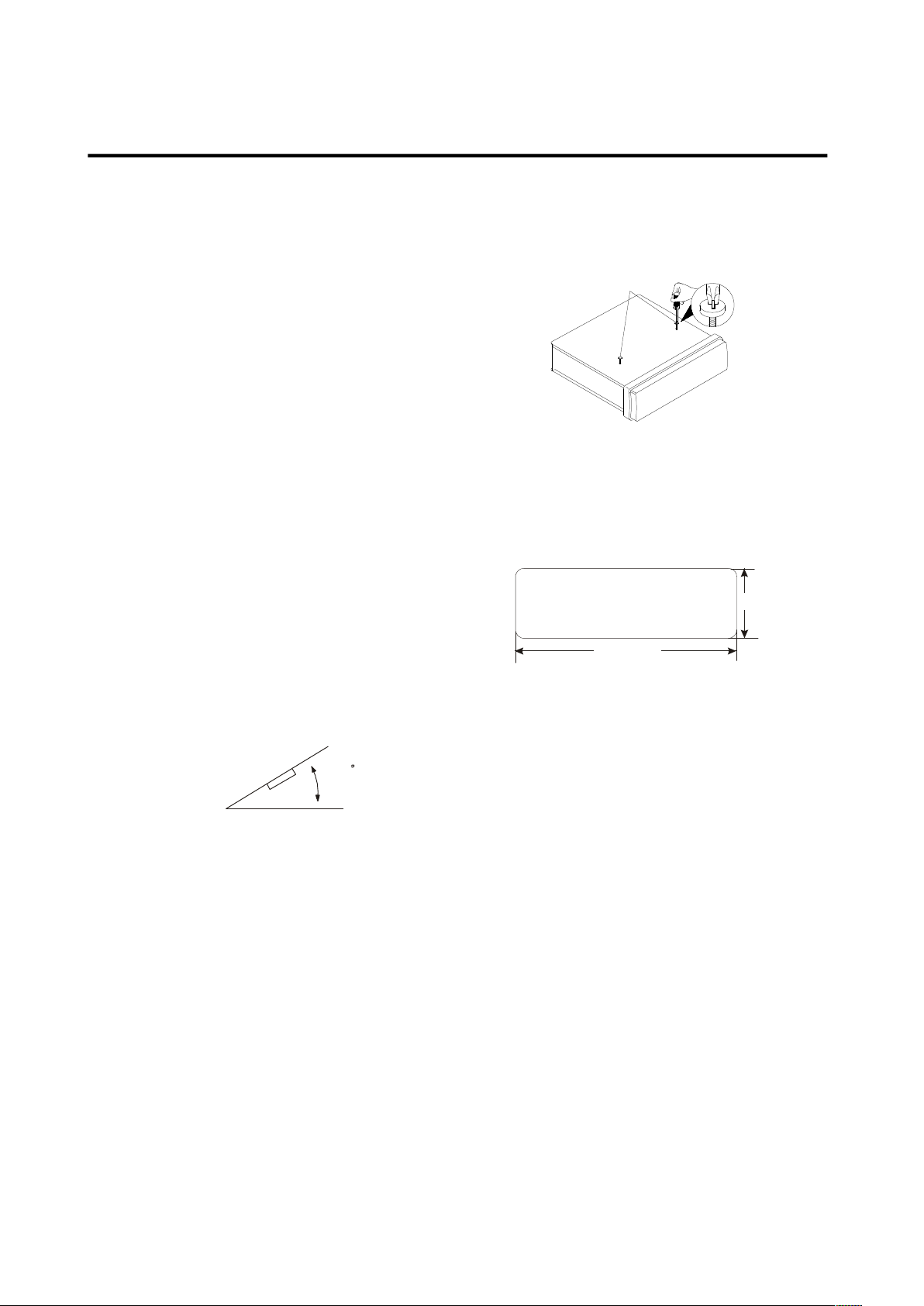
TAKEOUTSCREW BEFORE INSTALLATION
Before installing the unit, please remove
the two screws.
DIN FRONT-MOUNT (Method A)
Installation Opening
This unit can be installed in any dashboard
having an opening as shown below:
Installing the unit
Be sure you test all connections first, and
then follow these steps to install the unit.
1. Make sure the ignition is turned off, and
then disconnect the cable from the
vehicle battery’s negative (-) terminal.
2. Disconnect the wire harness and the
antenna.
3. Press the release button on the front
panel and remove the control panel
(see the steps of “removing the front
panel”).
4. Remove the trim ring by releasing the 2
clips on each of its two sides.
5. The two supplied keys release tabs
inside the unit’s sleeve so you can
remove it. Insert the keys as far as they
will go (with the notches facing up) into
the appropriate slots at the middle
30
53 mm
18 2mm
Take out screw
before installation.
Page 4
4
INSTALLATION
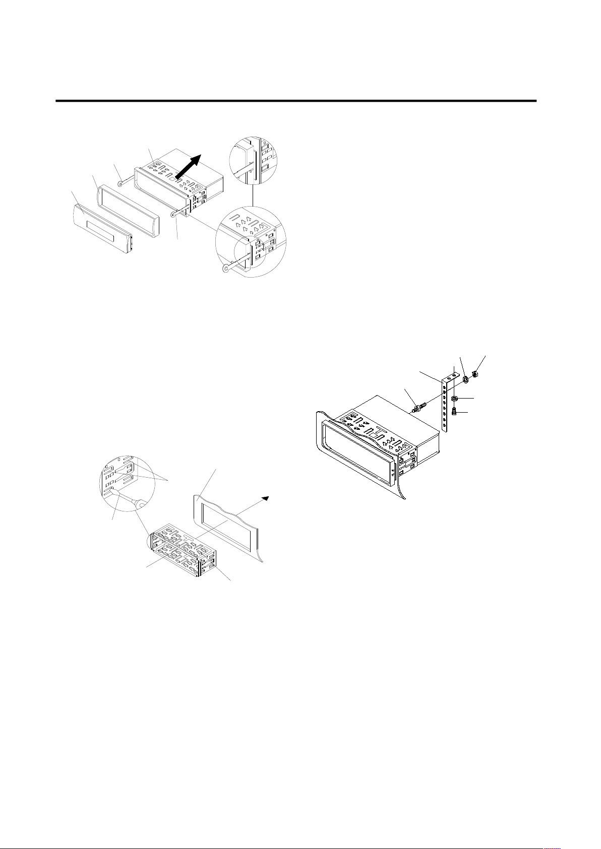
left and right sides of the unit. Then slide
the sleeve off the back of the unit.
6. Mount the sleeve by inserting the sleeve
into the opening of the dashboard and
bend open the tabs located around the
sleeve with a screwdriver. Not all tabs
will be able to make contact, so
examine which ones will be most
effective. Bending open the appropriate
tabs behind the dashboard to secure
the sleeve in place.
T
abs
S
crewdriver
Sleeve
Dashboard
7. Reconnect the wire harness and the
antennas and be careful not to pinch
any wires or cables.
8. Slide the unit into the sleeve until it
locks into place.
9. To further secure the unit, use the
supplied metal strap to secure the back
of the unit in place. Use the supplied
hardware (Hex Nut (M5mm) and Spring
Washer) to attach one end of
the strap to the mounting bolt on the back
of the unit. If necessary, bend the metal
strap to fit your vehicle’s mounting area.
Then use the supplied hardware
(Tapping Screw (5x25mm) and Plain
Washer) to attach the other end of metal
strap to a solid metal part of the vehicle
under the dashboard. This strap also
helps ensure proper electrical grounding
of the unit.
Note to install the short threading
terminal of the mounting bolt to the back
of the unit and the other long threading
terminal to the dashboard.
M
o
unting Bolt
Spring Washer
Plain Washer
Tapping Screw
Hex Nut
Metal Strap
10. Reconnect the cable to the vehicle
battery’s negative (-) terminal. Then
replace the outer trim ring and install the
unit’s front panel (see the steps of
“installing the front panel”).
Removing the unit
- Make sure the ignition is turned off,
then disconnect the cable from the
vehicle battery’s negative (-) terminal.
- Remove the metal strap attached the
back of the unit (if attached).
- Press the release button to remove the
front panel.
- Lift the top of the outer trim ring then
pull it out to remove it.
O
ut
er Trim Ring
Front Panel
L
K
ey
Sleeve
R Key
Page 5
5
INSTALLATION
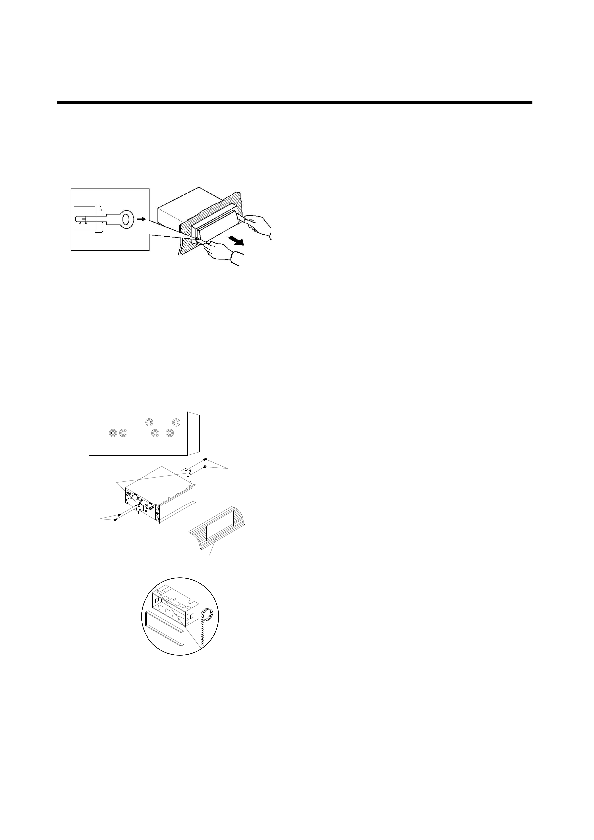
- Insert both of the supplied keys into the
slots at the middle left and right sides of
the unit, then pull the unit out of the
dashboard.
DIN REAR-MOUNT (Method B)
If your vehicle is a Nissan or Toyota, follow
these mounting instructions:
Use the screw holes marked T (Toyota), N
(Nissan) located on both sides of the unit to
fasten the unit to the factory radio mounting
brackets supplied with your vehicle.
D
ashboard or Console
Screw
F
actory Radio
Mounting Bracket
S
ide View showing
Screw Holes marked
T, N
Screw
Fastening the unit to the factory radio
mounting brackets:
Align the screw holes on the bracket with
the screw holes on the unit, and then
tighten the screws (5x5mm) on each side.
Note: the outer trim ring, sleeve and the
metal strap are not used for method B
installation.
Page 6
6
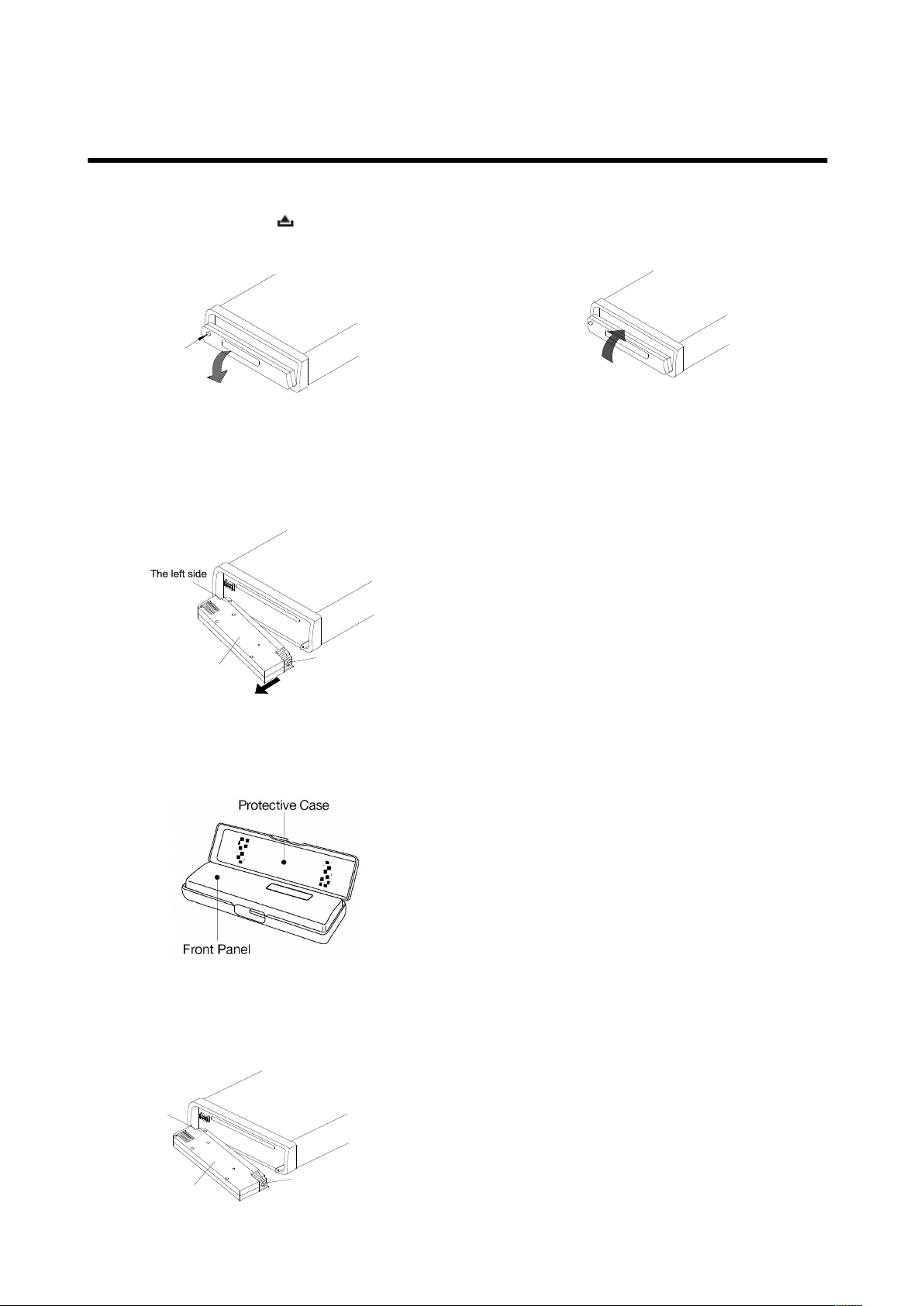
USING THE DETACHABLE FRONT PANEL
To Detach the Front Panel
1. Press the release ( ) button, the front
panel will fold down.
O
P
EN
2. To remove the front panel, lift it up at a
little angle from horizontal position, then
first pull out the right side and then pull
out the left side.
F
r
ont Panel
T
h
e right side
3. For safekeeping, store the front panel in
the supplied protective case immediately
after being removed.
To Install the Front Panel
1. To install the front panel, first insert the
left side into proper position then insert
the right side into place.
2. When the two sides are fixed into place,
push the front panel into main unit.
3. Note that if the front panel fails to lock in
position properly, pressing control
buttons may not function and the display
may be missing some segments. Press
the release button and then reinstall the
front panel again.
Precautions when handling
1. Do not drop the front panel.
2. Do not put pressure on the display or
control buttons when removing or
installing the front panel.
3. Do not touch the contacts on the front
panel or on the main unit body. It may
result in poor electrical contact.
4. If any dirt or foreign substance adheres
to the contacts, it can be removed with
a clean and dry cloth.
5. Do not expose the front panel to high
temperatures or direct sunlight.
6. Do not allow volatile agents (e.g.
benzene, thinner, or insecticides) to
touch the surface of the front panel.
7. Do not attempt to disassemble the front
panel.
T
h
e left sid e
F ro nt P an el
T he rig ht sid e
Page 7

7
WIRING CONNECTION
ISO CONNECTION
Page 8

8
OPERATION
LOCATION OF KEYS
1. 4/SHF
2. 1/
3. 5 DIR-
4. 2 SCN
5. 6 DIR+
6. 3 RPT
7. (
pick up)
8. VOL/PUSH/SEL/MENU
9.
10. Mic
11. LCD
12. USB interface
13. AUX IN
14.
15. MUTE
16. (Hang up)/LOU/BND
17. T-MENU/TRANS
18. SCAN/# (FM/AM modes only)
19.9/PTY
20. MODE/PAIR
21. */+/ AS/PS (Full DAB scan)
22. 0/DSP
23. 8/TA/EQ
24. 7 AF
25. (
Front panel release button
)
26. SD card slot
27. Reset button
28. CD slot
29. Eject button
Page 9

9
OPERATION
BASIC OPERATION
SWITCHING THE UNITON/OFF
Press any button to turn on the unit. When
the unit is on, press and hold the button
(15) to turn the unit off.
FACEPLATE RELEASE
Press button (25) to detach the
removable faceplate.
SOUND ADJUSTMENT
Press SEL button (8) to enter AUDIO
SETTING mode. The adjustment mode will
change in the following order:
Bass / Treble / Balance / Fader / VOL, turn
the volume knob to adjust the setting.
LOUDNESS
Press and hold LOUD button (16) to switch
the loudness function on, “LOUD” will
appear on the LCD for several seconds.
Press it again to release this function.
DISPLAY
Press DSP button (22) to show various
information such as clock, frequency, PTY
and so on.
EQUALIZATION
Press EQ button (23) to turn on
equalization function and to select desired
audio mode. There are five kinds of mode
as below:
→FLAT→CLASSICS→POP→ROCK→DSP OFF
RESET FUNCTION
RESET button (27) must be activated with
either a ballpoint pen or thin metal object.
The RESET button is to be activated for the
following reasons:
- Initial installation of the unit when all
wiring is completed.
- Function buttons do not operate.
- Error symbol on the display.
Note: if pressing RESET button (27), does
not solve the issue, clean the panel
contacts with isopropyl alcohol on a cotton
swab.
MODE SELECTION
Short press MODE button (20) to change
the mode: Radio, DAB, USB, SD PLAY and
AUX.
SYSTEM SETTING
Press and hold SEL button (8) on the front
panel to enter SYSTEM SETTING mode.
Items below can be adjusted:
BEEP / P-VOL / HOUR 24H
Use SEL button (8) to select the item you
want to change, and by rotating the volume
knob (8) to change the corresponding
setting.
1) BEEP ON/OFF:
Beep on: There is a beep sound when
buttons is pressed.
Beep off: There is no beep sound when
buttons is pressed.
2) P-VOL
P-VOL: The maximum volume value
when you turn on the unit.
Example, with P-VOL at 40 (default
value):
If the volume value is smaller than 40
when you turn off the unit, next time you
turn on the unit the volume will keep the
last volume value. But if the volume
value is higher than 40 when you turn off
the unit. Then next time you turn on the
unit. The volume value will back to 40.
Page 10

10
OPERATION
4) HOUR 24/12
You can select time format to 12 hour or 24
hour format.
AUXILIARY INPUT
A portable audio player can be connected
to the unit through the AUX IN jack (13) on
the front panel. After finishing the
connection, Press MODE button (20) to
switch the mode to AUX IN mode.
RADIO OPERATION FM/AM
SELECTING THE FREQUENCY BAND
In radio mode, press BAND button (16) to
select the desired band.
The reception band will change in the
following order:
FM1FM2FM3MW1(AM1)
SELECTING A STATION
Press / buttons (9/14) to activate
automatic seek function. It will search
up/down for a station automatically. Press
for 2 seconds until “MANUAL……” appears
on the display, the manual tuning mode is
selected. In this mode you can tune
up/down in 0.05Mhz steps. If both buttons
have not been pressed for several seconds,
they will return to seek tuning mode and
“AUTO……” appears on the display for 1
second.
AUTOMATIC MEMORY STORING &
PROGRAM SCANNING
Press and hold AS/PS button (21)
“SEARCH” will appear on LCD, the radio
will search from the current frequency and
checks the signal strength until one cycle
search is finished. The 6 strongest stations
are stored into the corresponding preset
number button.
A short press of AS/PS button (21) will
scan preset stations, and the
corresponding station number P1~P6 will
flash on the LCD.
STATION STORING
Search for a station first. Then press a
preset button (1-6) for 2 seconds (until
2’nd beep), current station is stored into
the number button.
RDS (RADIO DATA SYSTEM)
OPERATION
Setting RDS mode
Press AF button (24) and release
immediately to switch on or off AF
function.
Whenever RDS is switched on, the
symbol “AF” appears on the display.
The program name will be displayed on
receiving an RDS station.
“AF” starts blinking if the broadcasting
signal is getting worse.
“ALARM” will be displayed when an
emergency broadcast is received;
meanwhile sound output level will be
adjusted to the preset output level
automatically when the volume control is
smaller than TA VOL value.
Using PTY to Select Program:
1) Press PTY button (19). Then press
preset button (1-6) , (or use the volume
knob) to select programs below:
Button 1: AFFAIRS / INFO / SPORT /
EDUCATE / NEWS
Button 2: DRAMA / CULTURE /
SCIENCE / VARIED / POP M
button 3: ROCK M / EASY M / LIGHT
M / CLASSICS / OTHER M
Page 11

11
OPERATION
Button 4:WEATHER / FINANCE /
CHILDREN / SOCIAL / RELIGION
Button 5: PHONE IN/ TRAVEL/
LEISURE / JAZZ / COUNTRY
Button 6: NATION M / OLDIES / FOLK
M / DOCUMENT / TEST /ALARM.
Then press / buttons (9/14) to
begin searching for the corresponding
program.
RDS MENU
Note, these are advanced settings and
best left as default unless you are an
expert user.
1)Press and hold PTY button (19) for 2
seconds to enter RDS MENU. Short
press PTY button (19) again to show
below items:
TA---PI---RETUNE---MASK---EONTA
---TAVOL---REG
In each item above rotating knob (8) will
select the corresponding setting desired.
TA: SEEK/ALARM
a) TA SEEK mode (default)
When a newly tuned station does not
receive TP information for 5 seconds,
the radio retunes to the next station
which has a different station (PI) as the
last station, but has the same TP
information.
When TP information gets lost on the
current station, for longer than the retune
time, which is set by RETUNE SHORT
or RETUNE LONG, the radio will retune
to next equivalent PI station.
Note: In TA SEEK mode, the current
station can be changed to a completely
different station because the unit
searches TP stations when the field
(signal) strength of the current station is
very weak, or the current station has no
“TP” signal.
(The higher priority is TP rather than
PI.)
b) TA ALARM mode
When this mode is selected, automatic
retune mode is not activated. Instead a
double beep sound (ALARM) is output
the unit keeps the current station. (The
PI priority is higher than TP.)
When a newly tuned station doesn’t
have TP information for 5 seconds, unit
will beep. When TP information gets lost
at the current station for retune time, unit
will beep. When a newly tuned station
has no RDS signal, “PI SEEK” is
suppressed.
PI: SOUND/MUTE:
When the vehicle is crossing an area
where two stations with same AF but
different PI code can be received at the
same time, the receiver will become
unstable; under this situation two modes
can be selected:
a) PI SOUND mode (default)
The different PI sounds will be heard
b) PI MUTE mode:
Under above same situation, the radio
will be muted.
RETUNE: LONG/SHORT
When PI information gets lost on the
current station the radio will retune to
next matching PI station after the preset
retune time:
Retune Long 90 seconds
Retune Short 30 seconds
Page 12

12
OPERATION
MASK: DPI/All
MASK DPI mode
Masks only the AF which has a different
PI (DPI).
MASK ALL mode
Masks the AF which has Different PI and
no RDS signal with high field strength.
EONTA DX/LO (DISTANCE/LOCAL)
The purpose of this key is to reduce
unwanted EON TA switching. When
EON TA information is received from the
current station, the radio switches to that
EON linked station, but no information is
be received because the EON linked
station is located too far from that area,
so the radio is switches back to current
station again. In the above operation, the
user listens to a wrong program or poor
signal reception for a while
EON TA LOCAL mode
(Default)
When the signal strength level of the
EON linked frequency is less than the
threshold level, the radio does not switch
to that station, and the listener does not
hear any disturbances.
EON TA DISTANCE mode
The radio will always try to switch to TA
EON linked signals even when the
reception may be poor.
TA-VOLUME: Volume 30 (the default TA
volume value is 30).
When a Traffic Announcement is
received, If the main volume is set lower
than the TA VOL value. It will turn up the
main volume to the TA VOL value.
REG: OFF/ON
REGION ON mode:
AF switching or PI SEEK is implemented
to stations which have identical PI codes
as the current station.
REGION OFF mode: The regional code
in the format of the PI code is ignored
when AF switching or PI SEEK is
implemented.
Listening to Traffic Announcements
When TA mode is on (TA shows in the
display) and a traffic announcement is
transmitted, the radio will switch
temporarily to the EON linked station
for the broadcast. If the unit was in
DAB/USB/SD or AUX IN mode, it will
switch temporarily to FM radio mode.
If the volume level was under the
threshold point it will be raised to the
threshold point. But if the user has
changed the volume level to more than
the threshold point (min. TA volume
level), it will be set to the last level.
When TA mode is on, TA will show in the
display
The current traffic announcement can be
cancelled by pressing 8/TA/EQ(23).
TA mode will remain on.
RDS abbreviations:
PI: Program Identification code
Code for identifying programs
PS: Program Service Name
Broadcast station name data
expressed in alphanumeric
characters
AF: Alternative Frequencies
Frequency list of broadcasting
stations transmitting the same
program
TP: Traffic Program Identification
Identification data for traffic
information-broadcasting station
Page 13

13
OPERATION
TA: Traffic Announcement Identification
Identification data showing if traffic
information is being transmitted or
not.
EON: Enhanced Other Networks
Information
Broadcasting information on PI, AF,
TP, TA, etc, relating to networks
other than the network used for
current reception
PTY: Program Type Code
Contents of programs such as
news, light music, sports etc.
DAB OPERATION
1) Press mode button (20) until DAB is
displayed at the top of the LCD
2) Press AS/PS button for DAB full scan. If
there are no signals found "NO
STATION FOUND" will be displayed
3) Press / buttons (9/14) to change
up/down channels
4) Press and hold M1-M6(2/4/6/1/3/5)
button to store the current station to a
M1-M6 station preset.
5) Short Press M1-M6(1/2/3/4/5/6)
buttons to select presets M1-M6.
6) Press DSP (22) to show various
information (This is rotates in the
sequence below)
Station name -> Ensemble name ->
Current Frequency -> Current PTY ->
DLS Message -> CLOCK -> Signal
Strength -> Signal Quality -> Station
name
7) List Search mode
Press PTY button to enter/exit List
Search mode.
In list search mode rotating the Volume
UP/DOWN(8) displays station names
without directly tuning to them. Press
SEL button to select the currently
Listed Station.
* In this mode LCD display blinks
CD/MP3/WMA OPERATION
SWITCHING TO CD MODE
Press (25) front panel release, lower the
panel, gently insert a CD label side up
into the CD slot and close the front panel.
The unit will switch to CD mode and
begin playback.
If a CD is already in the drive press
MODE button (20) untill the CD mode
appears and playback will begin.
SELECTING TRACKS
Press / buttons (9/14) to skip to the
Next/previous track/file. Track/file
number will be shown on the display.
Press and hold / buttons (9/14) for
2 seconds to fast forward/reverse . File
play starts when releasing the button.
PAUSING PLAYING
Press button (2) to pause the
playing. and “Pause” will appear on LCD.
Press it again to resume play.
PREVIEWING ALL TRACKS
Press SCAN button (18) to play the first
several seconds of each track, “SCN” will
show in the display, press again to stop
scan and listen to the track.
Press and hold SCAN button (18) to play
the first several seconds of each track in
the current folder (MP3) and “D-SCN” will
appear, press it again to exit this mode.
REPEATING THE SAME TRACK
Press RPT button (6) to continuously
repeat the same track. and “S-RPT” will
appear on LCD. Press it again to stop
repeat, and “S-RPT” will disappear.
Page 14

14
OPERATION
Press and hold RPT button (6) to repeat all
the files in the current folder (MP3) or on
the CDA disk. “D-RPT” will appear on LCD.
Press it again to exit this mode.
PLAYING ALL TRACKS IN RANDOM
Press SHF button (1) to play all files in
random order, and “S-SHF” will appear on
LCD. Press again to cancel the function,
and “S-SHF” will disappear.
Press and hold SHF button (1) for 2
seconds will play all files in the current
folder in random order. And “D-SHF” will
appear on LCD. Press it again will exit this
mode.
EJECTING A DISC
Open the front panel and Press button
(29) to stop CD/MP3/WMA play and eject
the disc from the disc slot (29).
ESP FUNCTION
The unit has a shockproof function, with a
memory of 30 seconds for CD and 90
seconds for MP3/WMA file (128k
bitrates/44.1 kHz sampling).
SELECTING DIRECTORY UP/DOWN
Press DIR- button (3) or DIR+ button
(5), to select directory down or up. If the
disc/USB driver does not
contain any directory, there will be no
function If the disc is a CD disc (CDDA).
Press DIR-/DIR+ button to skip to -10/+10
songs.
SELECTING TRACKS (for MP3/WMA)
Searching Tracks Directly
Press AS/PS (SCH) button (21) one time.
This enters into “Searching track directly”
mode.
The unit searches the track selected by
following direct numeric buttons:
M1-M6, 7/AF, 8/TA/EQ, 9/PTY, 0/DSP. You
can also rotate the button (8) to select the
numbers.
If selecting three digits, the unit searches
the track at once. If selecting one or two
digits, the unit waits for BND/LOU or SEL
button for a few seconds. The unit then
searches the track even if the enter button
is not pressed.
Searching Directory or File Name
Press AS/PS (SCH) button (21) two times.
This enters into “Searching Directory or
File Name” mode.
The unit searches files and directories
that have the same character which is
input by the user pressing the
corresponding buttons listed on the
following page.
AS/PS
Mode Select
BND/LOU
ENTER
M1
A, B, C, 1
M2
D, E, F, 2
M3
G, H, I, 3
M4
J, K, L, 4
M5
M, N, O, 5/Directory
DOWN
M6
P, Q, R, 6/Directory UP
MOD
S, T, U, 7
TUNE/SEEK/TRACK
DOWN
V, W, X, 8
TUNE/SEEK/TRACK
UP
Y, Z, SPACE, 9
PUSH SEL
CHARACTER SHIFT
RIGHT
DSP
_,-,+,0
AUDIO KNOB
CHARACTER SELECT
(A, B~8,9,0, _,-,+,)
Searching track/directories (MP3)
1. Use the corresponding buttons, or
using button (8) to select the
characters A to Z, blank, 0 to 9, _, -,
+.
2. Press SEL button (8) to confirm
entry of each character.
3. Press BND/LOU button (16) to start
the song search.
In case the selected title is a
Page 15

15
OPERATION
directory name, please use button (4)
to list all songs under this directory
and select a song.
4. Press BND/LOU or SEL button to
confirm and start playback.
5. If the newly selected title is another
directory repeat the above steps.
Searching From the Root Directory
Press AS/PS (SCH) button (21) three
times. The unit searches file or directory
from the root by button (8). The display
will list all available directories and
Songs. Select the desired
directory/songs by using buttons (8) and
BND/LOU or SEL button to confirm. If
the selected title is a song, it starts to
play. If the selected title is a directory
name, then use the buttons (8) to list all
songs under this directory, and select a
song, Press BND/LOU or SEL button to
confirm and start playback.. Repeat the
above steps if the newly selected title is
another directory.
Searching FILE From Current
Directory
Press AS/PS (SCH) button four times.
The unit searches files or directories
from current directory by button (8). The
currently playing file name is displayed,
and can be selected by button (8). After
selecting a file, press BND/LOU or SEL
button to play. If you would like to listen
to a song which is in a different directory,
select (‘ ‘) and press SEL button,
select desired directory and press SEL
button to enter it. After selecting a song
press BND/LOU or SEL button to play.
DISPLAY ID3 INFORMATION
Press DSP button (22) to show the ID3
TAG (title, artist and album).
SUPPORT MP3/WMA DECODING
MODE
The main unit supports MP3/WMA
(Windows Media Audio) decoding
modes as below.
Standard
Bit Rate (kbps)
Supports Mode
MPEG1
Audio Layer
3 (44.1kHz)
32,48,64,96,
128,192,256,
320
Stereo
Windows
Media Audio
(44.1kHz)
64,96,128,192
Stereo
The USB operation can support:
Folder: 500 max; File 999 max; Size
2GB; Depth of folders (directories) 8
layers
DISC NOTES
A. Notes on discs:
Do not stick paper or tape, etc, onto the
label side or the recording side of any
discs, as it may cause a malfunction.
Dirt, dust, scratches and warping discs
will cause various malfunctions.
B. Notes on CD-Rs (recordable
CDs)/CD-RWs (rewritable CDs):
1. Be sure to use discs with following
marks only for the unit to play:
2. The unit cannot play a CD-R or CD-RW
that is not finalized. (Please refer to the
manual of your CD-R/CD-RW recorder
or CD-R/CD-RW software for more
information on the finalization process).
3. Depending on the recording status
conditions of the disc and the
equipment used for the recording, some
CD-Rs/CD-RWs may not be played on
this unit (see 1).
4. To experience more reliable play back,
please see following recommendations:
a: Use CD-RWs with speed 1x to 4x
ReWritable
Page 16

16
OPERATION
and write with speed 1x to 2x.
b. Use CD-Rs with speed 1x to 8x and
write with speed 1x to 2x.
c. Do not play a CD-RW which has
been written for more than 5 times.
C. Notes on MP3 files
1. The disc must be in ISO9660 level 1 or
level 2 formats, and Joliet or Romeo in
expansion format.
2. When naming a MP3 file, be sure the file
name extension is “.MP3”.
3. A non-MP3 audio file, with a file name
extension of “.MP3” will not be
recognized.
USB PLAYBACK
The USB interface (12) is located under the
small flap on the right side of the front panel.
When you connect an USB stick into the
interface, the unit will search MP3/WMA
files in the USB stick and start to play
automatically.
If in other mode, press MODE button (20)
to select “USB”
Note:
This unit can only support standard
USB-memory drives approved by
Microsoft.
USB MP3 players are not standardized
which means different brand names
and different models have their own
standard. This product cannot
necessarily support every MP3 player.
When connecting an MP3 player with a
none rechargeable battery, please
remove the battery before using it in
your radio, otherwise there is a risk of
fire.
SDCARDPLAYBACK
The SD interface (26) is located under the
front panel. To insert a card remove the
front panel completely to access the slot.
The unit will search MP3/WMA files on the
card and start to play automatically.
The use of SD cards is the same as MP3
operation described for USB. If unit is in
other mode, press MODE button (20) to
select SD mode.
CAUTION
When there are other important files on the
USB device/SD card. Do not connect it to
the main unit to play as in rare
circumstances file loss could occur.
BLUETOOTH PLAYBACK
PREPARATION
(i) When using Bluetooth, please make
sure your mobile phone supports
Bluetooth mode
(ii) It is recommended that the distance
between the mobile phone and the unit
is within 3m; please don’t put any metal
object or any obstacle between the path
of the mobile phone and the unit.
PAIRING
1) In any mode, press and hold
PAIR(MODE) button (20) on the front
panel, “PAIRING” will appear on the
LCD.
2) On the mobile phone, select the
Bluetooth set up. (Please refer to the
instruction manual of your mobile phone
on how to operate Bluetooth.)
3) “CCE5063” should appear in the list
on your mobile phone, please select
“CCE5063” and then input password
Page 17

17
OPERATION
“0000” when prompted.
4) When successfully paired, “CONN
OK!” will be displayed on radio display.
5) If pairing fails, “PAIR END” will be
displayed on radio display. You can
press and hold PAIR button (20) to try
the pairing again.
6) Note:
During Pairing, the MODE key will not
function, during pairing mode you can
press PAIR button (20) to terminate
pairing.
CONNECTION
This unit has a built-in
auto-reconnection function. Every time
you short press button (7), the unit
will auto reconnect with the mobile
phone, (note: the mobile phone must
have been paired with the unit before).
1) If the mobile phone is out of range,
the connection will be lost, when you
come back to the unit, reconnection is
necessary.
2) If the mobile phone is out of range
and there is an incoming call, when
you come back within range, and you
want to transfer the audio to the radio,
you need to reconnect.
3) When you press button (25) to
release the front panel, the connection
will be lost. When you install the front
panel, you need to reconnect.
If you turn off the mobile phone that
has paired with the unit, when you
turn on the mobile phone, you need to
reconnect.
T-MENU
When successfully paired, short press
of T-MENU button (17) on the front
panel will enter the telephone menu,
keep pressing this button or press
/ button (9/14) to change the
items in this menu. The items will be
displayed in the following sequence:
PRE NUM/ RECELVED / DIALED /
MISSED / PHONE BK / MANU ANS /
TALK.
For details please see the following
instruction.
1) RRE NUM: You can save 10
phone-calls to phonebook 1. In PRE
NUM mode, rotating button (8) to
select the NUMBER. Then press SEL
button, and enter the phone number.
Then press SEL button again to save
it to phonebook 1.
If you want to delete a number from
phonebook 1. after selecting the
number press and hold BND/LOU/
key for 2 seconds. The number
will be deleted.
2) RECEIVED: Display the last calls
you have received (10 numbers).
3) DIALED: Display the last dialed
numbers (10 numbers).
4) MISSED: Display the calls you have
missed (10 numbers).
PHONE BK:
You can copy 20 phone numbers you’re
your mobile phone to phone book 2 of the
unit via Bluetooth connection, see
instruction book of your phone. If you need
to delete numbers from phone book 2,
select the number, then press and hold
BND/LOU/ key for 2 seconds. The number
will be deleted
5)MANU ANS (manual answer):
Page 18

18
OPERATION
You can set Answer mode to manual
answer (MANU ANS) mode or Auto
Answer (AUTO ANS) mode.
In auto answer mode, when a call
comes in the phone number will
appear on the LCD. The unit will
answer the call automatically.
In MANU ANS mode, when a call
comes in, the phone number will
appear on LCD. you can press
button (7) to answer the call, or press
button (16) to reject the incoming
call.
6) TALK (00~20):
You can set the bluetooth volume in
TALK xx. If it is 00, when there is a
call coming in the main volume will
set to 60 automatically. If you set
TALK to 20. The main volume will set
to 100 automatically when a call
comes in.
Example:
TALK volume MAIN volume
00 = 60
01 = 62
02 = 64
……………………..
20 = 100
MAKING AN OUTGOING CALL
1) Making an outgoing call from
SPEED DIAL, RECEIVED LIST, DIALED
LIST, MISSED LIST, PHONE BOOK
(Mobile Phone) and PHONE BOOK (SIM
Card) please refer to the T-MENU
section.
2) To make an outgoing call by
inputting the phone number manually.
Press button (7) on the front panel
“CALL_” will appear on LCD. Use 0~9,
*,
# buttons to enter the phone number you
want to dial. (Note: short press * button
will input “*” character, press and hold it
will input “+” character). Then press
button (7) again to call the number.
Note: if you input the wrong number,
short press BND button to clear it. Press
and hold BND button to clear whole
number.
TRANSFER THE CALL BETWEEN
MOBILE PHONE AND THE UNIT
During the talk mode, you can press and
hold TRANSFER (T-MENU) button (17)
to transfer the phone call between the
mobile phone and the unit.
Note:
1) If you transfer the call to mobile phone,
the mute of the present mode will be
released at the same time.
2) When making an outgoing call, it’s
not possible to transfer if the call has not
been answered yet.
BT reset
In BT AUDIO mode, press and hold
#SCAN key for several seconds. Some
of the Bluetooth information and phone
numbers will be lost.
BLUETOOTH AUDIO
The unit supports Bluetooth audio. when
the unit is paired, you can play music
from your phone.
M1, M2, button on the front panel of the
unit serves as PAUSE/PLAY and STOP
control buttons. Phones may vary in
how they use these buttons.
Use the / buttons (9/14) on the front
panel of the unit to choose the
previous/next track. (Some phones will
not use this function)
Page 19

SPECIFICATION
GENERAL
Power Supply Requirements : DC 12 Volts, Negative Ground
Chassis Dimensions : 178 (W) x 160 (D) x 50 (H)
Tone Controls
- Bass (at 100 Hz) : ±10 dB
- Treble (at 10 kHz) : ±10 dB
Maximum Output Power : 4x40watts
Current Drain : 15 Ampere (max.)
RADIO
(Europe)
FM
Frequency Coverage 87.5~108 MHz
IF 10.7 MHz
Sensitivity (S/N=30dB) 4μV
Stereo Separation >25dB
MW
Frequency Coverage 522~1620 KHz
IF 450 KHz
Sensitivity (S/N=20dB) 36dBuV
DAB
Frequency Coverage 174.928~239.200 MHz
Sensitivity (S/N=20dB) ≥-100dBuV
Preset stations 18
CONTACT DETAILS
We trust you are co mpletely satisfi ed with this p roduct from Argos Ltd, ho wever
please feel free to contact us if you experience any difficulties, or if you would like
to express your views regarding our products.
Please write to:
Customer Services
Argos Ltd
489-499 Avebury Boulevard
Saxon gate West
Central Milton Keynes
MK9 2NW
Telephone No.: 0870 600 3030
Through the process of continuous improvement, Argos Limited reserves the right
to change or alter specifications without prior notice. E&OE
19
Page 20

TROUBLE SHOOTING
Before going through the checklist, check your wiring connections. If any of the
problems persist after checklist has been made, consult your nearest service dealer.
Symptom Cause Solution
No power.
Disc cannot
be loaded or
ejected.
No sound.
Sound skips.
The operation
keys do not
work.
The car ignition switch is
not on.
If the power supply iconnected
to the car accessory circuits,
but the engine is not moving,
switch the ignition key to“ACC”.
The fuse is blown. Replace the fuse.
Temperature inside the
car is too high.
Cool off or until the ambient
temperature return to normal.
Condensation. Leave the player off for an hour
or so, then try again.
Volume is at minimum Adjust volume to a desired level.
Wiring is not properly
connected.
The installation angle is
more than 30 degree.
The built-in microcomputer
is not operating properly
due to noise.
Check wiring connection.
Adjust the installation angle less
than 30 degree.
Press the RESET button.Front
panel is not properly fixed into
place.
The radio does
not Work. The
radio station
The antenna cables are
not connected.
Insert the antenna cables firmly.
The signals are too weak. Select a station manually.
automatic
selection does
not work.
INFORMATION FOR THE CONSUMER
Disposal of your old product Your product is designed and manufactured
with high quality materials and components, which can be recycled and
reused. When this crossed out wheeled bin symbol is attached to a product
it means the product is covered by the European Directive 2002/96/EC.
Please make yourself aware of the local collection system for electrical and
electronic products. Please act according to your local rules and do not
dispose of your old products with your normal household waste. The correct
disposal of your old product will help prevent potential negative
consequences for the environment and human health.
20
Page 21

Guarantee
This product is guaranteed against manufacturing defects for a period of
PRODUCT GUARANTEE
Year
This product is guaranteed for twelve months from the date of original purchase.
Any defect that arises due to faulty materials or workmanship will either be replaced,
refunded or repaired free of charge where possible during this period by the dealer from
whom you purchased the unit.
The guarantee is subject to the following provisions:
The guarantee does not cover accidental damage, misuse, cabinet parts, knobs or
consumable items.
The product must be correctly installed and operated in accordance with the instructions
contained in this manual.
It must be used solely for domestic purpose.
The guarantee will be rendered invalided if the product is re-sold or has been damaged by
inexpert repair.
Specifications are subject to change without notice.
The manufacturer disclaims any liability for the incidental or consequential damages.
The guarantee is in addition to, and does not diminish your statutory or legal rights.
Guarantor: Argos Limited
489 - 499 Avebury Boulevard
Central Milton Keynes
MK9 2NW
 Loading...