

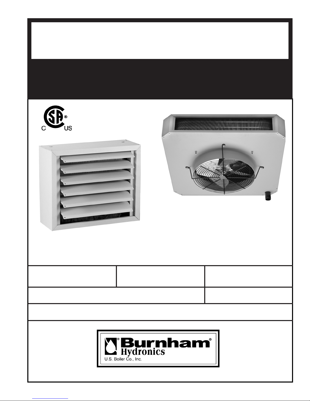
Page 1
DNAGNITAREPO,NOITALLATSNI
ROFSNOITCURTSNIECIVRES
™
HB
™
VBDNA
SRETAEHTINU
RETAWTOHROMAETSROF
sserddA
8144A001R4-2/07
.retaehehtfopotnodetacollebaL
rebmuNledoMrebmuNlaireSetaDnoitallatsnI
rot
cartnoCgnitaeH rebmuNenohP
gnikeesnehW.rotcartnocgnitaehruoyllac,retaehotsriaperroecivresroF
gnitaRnonwohssarebmuNlaireSdnarebmuNledoMedivorp,retaehnonoitamrofni
Page 2

TABLE OF CONTENTS
I. PRECAUTIONS - IMPORTANT INFORMATION .................................................3
II. GENERAL INFORMATION
A. Installation Limitations ..............................................................................................4
B. Inspection on Arrival .................................................................................................4
III. INSTALLATION
A. Special Precautions ....................................................................................................4
B. Unit Suspension ........................................................................................................4
C. Unit Heater Mounting Height ....................................................................................5
D. Piping Installation ......................................................................................................5
E. Wiring Instructions .....................................................................................................5
IV. OPERATION
A. Prior to Operation ......................................................................................................8
B. Initial Start-up ............................................................................................................8
V. MAINTENANCE
A. Regular Inspection .....................................................................................................9
B. Motors ........................................................................................................................9
C. Casings .......................................................................................................................9
D. Coils ...........................................................................................................................9
VI. APPLICATION GUIDELINES
A. General Guidelines ..................................................................................................10
B. Steam Performance Data .........................................................................................11
C. Selection Procedure - Steam Application ................................................................12
D. Steam Calculation Formulas ....................................................................................13
E. Steam Correction Factors .........................................................................................14
F. Hot Water Performance Data ....................................................................................17
G. Selection Procedure - Hot Water Application ..........................................................18
H. Hot Water Calculation Formulas .............................................................................19
I. Hot Water Correction Factors ...................................................................................20
VII. OPTIONS, ACCESSORIES AND CONTROL SEQUENCES
A. Field Installed Options for Horizontal and Vertical Models ....................................21
B. Control Sequences ...................................................................................................21
C. Field Installed Options for Horizontal Models Only ...............................................21
D. Field Installed Options for Vertical Models Only ...................................................22
VIII. DIMENSIONAL DATA
A. BH Dimensional Data ..............................................................................................25
B. BV Dimensional Data ..............................................................................................26
IX. MOTOR DATA ...........................................................................................................27
WARRANTY ................................................................................................Back Cover
2
Page 3

I. IMPORTANT INFORMATION - READ CAREFULLY BEFORE INSTALLATION
The following terms are used throughout this manual to bring attention to the presence of hazards of various risk levels, or to
important information concerning product life.
ECITON
nosnoitcurtsnilaicepssetacidnI
ecnanetniamro,noitarepo,noitallatsni
otdetalertontubtnatropmierahcihw
.sdrazahyrujnilanosrep
GNINRAW
suodrazahyllaitnetopasetacidnI
dluoc,dediovatonfi,hcihwnoitautis
royrujnisuoires,htaednitluser
.egamadytreporplaitnatsbus
GNINRAW
ytreporpesuacnacecnanetniamroecivres,noitaretla,tnemtsujda,noitallatsnireporpmI
reporpehtnisnoitcurtsnillawollofoteruliaF.efilfossolroyrujnilanosrep,egamad
lladnatsrednudnadaeR.egamadytreporproyrujnilanosrepesuacnacredro
sihtgnicivresrogniniatniam,gnitarepo,pu-gnitrats,gnillatsnierofeb,snoitcurtsni
ehraendetsopdnanoitidnocelbigelnierutaretildnalaunamsihtpeeK.retaeh
.naicinhcetecivresdnarenwoybecnerefer
aegdelwonkdnadelliks
.secafrus
.n
erdlihcraenesuninoituacemertxeesU
.ycnegaecivresrorellatsnielb
rofreta
,decneirepxenaybylnodemrofrepebtsumecivresdna,ecnanetniam,noitallatsnI
tohhcuotnikserabteltonod,snrubdiovaoT.TOHsi,noitareponinehw,retaehsihT
.gnitareposiretaehehtrevenehwnoituacemertxeesU
uteR.snoicnuflamretaehehtretfaretaehynaetarepotonoD
.riaperronoitanimaxerofytilicafecivres
tonoD
.sroodtuoesu
.rerutcafunamehtyb
dezirohtuanaotretaehnr
dednemmocertonsiesurehtoynA.launamsihtnidebircsedsaylnoretaehsihtesU
ECITON
.launamsihtfokcabehtnodetnirpsihcihwfoypoca,ytnarrawdetimilasahrotaidarsihT
dnadeniatniam,dellatsnineebsahrotaidarehtfiylnodilavsirotaidarsihtrofytnarrawehT
.snoitcurtsniesehthtiwecnadroccanidetarepo
3
Page 4
II. GENERAL INFORMATION
A. INSTALLATION LIMITATIONS
Installation and service instructions in this manual are
applicable to the steam/hot water unit heaters which
should be installed in their proper applications for their
most effective function as overhead heating units. The
copper coils are warranted for operation at steam or
hot water pressures up to 150 psig, and/or temperatures
up to 375°F. Canadian Standards Association (CSA)
requirements state that explosion-proof units may not
be used with a fl uid temperature in excess of 329°F and
still maintain their explosion-proof rating, for national
electric code ignition temperature rating T3B for grain
dust.
B. INSPECTION ON ARRIVAL
1. Inspect unit upon arrival. In case of damage, report
immediately to transportation company and your
local Burnham Hydronics Representative.
GNINRAW
DRAUGNAFTELTUOEVOMERTONOD
.STINUVBLEDOMMORF
2. Check rating plate on unit and motor to verify that
power input and motor specifi cation meet available
electric power at point of installation.
3. Inspect unit received for conformance with
description of product ordered (including
specifi cations where applicable).
III. INSTALLATION
A.
SPECIAL PRECAUTIONS
1. Disconnect power supply before making wiring
connections to prevent electrical shock and
equipment damage. All units must be wired strictly
in accordance with wiring diagram furnished with
unit.
2. Units should not be installed in atmospheres where
corrosive fumes or sprays are present.
3. Units must not be installed in potentially explosive
or fl ammable atmospheres.
4. Be sure no obstructions block air intake or air
discharge of unit heater.
5. Do not install unit above recommended maximum
mounting heights (see Table 1) or below the
minimum height of eight feet.
B. UNIT SUSPENSION
Horizontal Delivery Units, Model BH Series
All horizontal delivery units have two tapped holes
(3/8”-16) in the top for unit suspension. Piping
support hangers or clamps are recommended and
should be placed as close to the unit heater as
possible. For other models, independent suspension
can be made with threaded rods, pipes, or ceiling
hanger brackets.
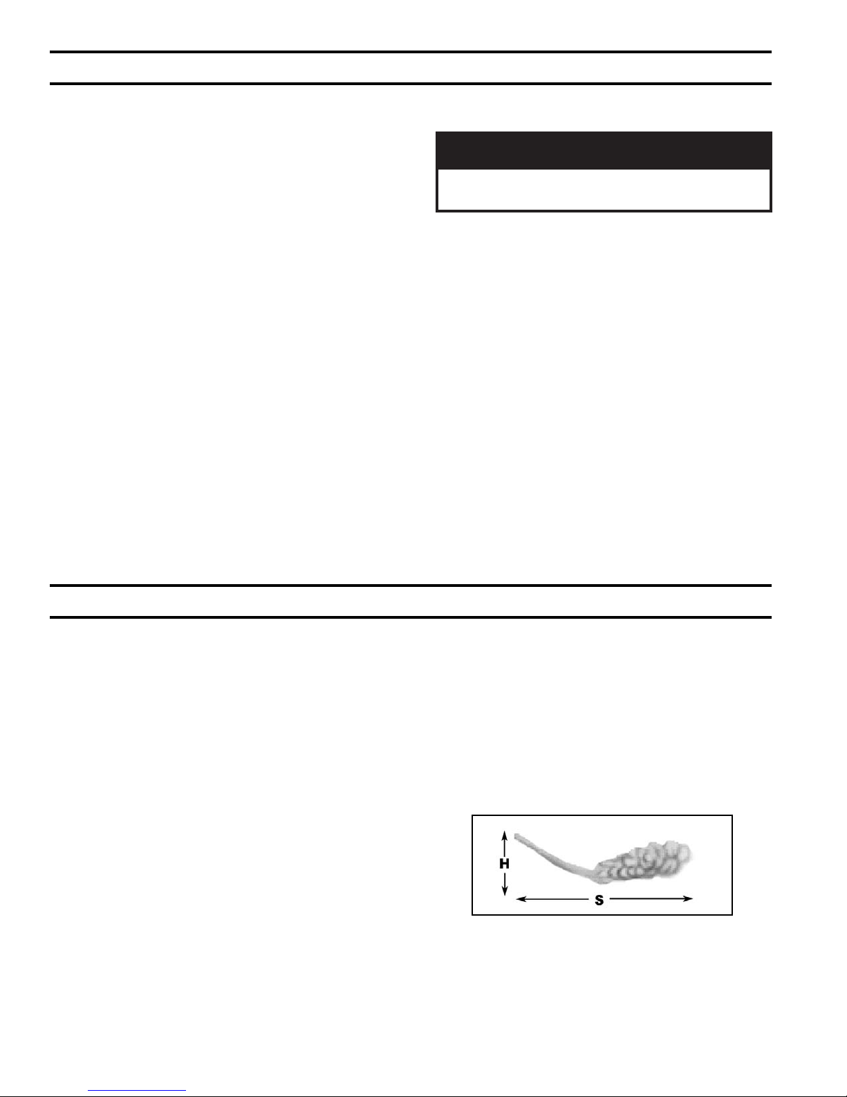
Figure 1: Horizontal Air Delivery
4
Page 5
Vertical Delivery Units, Model BV Series
Models BV-42 through BV-161 have 4 tapped holes
(1/2”-13) on the top surface for unit suspension.
Suspension can be made with threaded rods, pipes,
or ceiling hanger brackets. Models BV-193 through
BV-610 have angle-iron frame mounting brackets for
heavy-duty installation with applicable hardware.
No Defl ector
accessories. Locate horizontal delivery unit heaters so
air streams of individual units wipe the exposed walls
of the building with either parallel or angular fl ow
without blowing directly against the walls. Heaters
should be spaced so the air stream from one supports
the air stream from another heater. Locate vertical
delivery unit heaters in the center area of the space to
be heated, using horizontal delivery unit heaters along
the walls where heat loss is usually greatest.
D. PIPING INSTALLATION
Horizontal and Vertical Unit Heaters
Note: Only make piping connections using two (2)
pipe wrenches. One wrench is used as a “back-up”
while the other wrench is used for applying force
necessary to tighten the fi tting.
Two-Way Louver
4-Cone Anemostat
Truncone
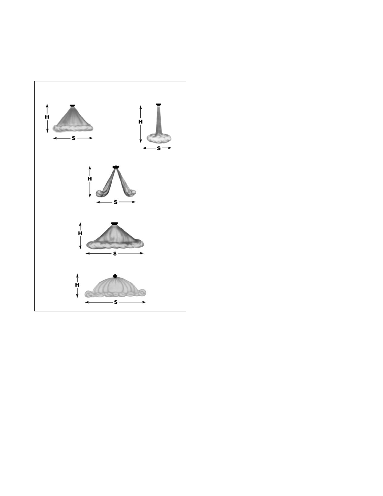
Figure 2: Vertical Air Delivery
C. UNIT HEATER MOUNTING HEIGHT
Do not install unit above recommended maximum
mounting heights or below the minimum height of eight
feet. The height at which unit heaters are installed is
critical. Maximum mounting heights for all units are
listed in Table 1. Maximum mounting heights for Model
BV is given for units with or without air diffusion
The illustrations, on page 6, suggest four (4) different
piping confi gurations. Refer to the ASHRAE Guide &
Specialty Manufacturer for selection of fi lter, piping
traps and other specialty sizing. Piping is typical for
unit heaters.
E. WIRING INSTRUCTIONS
1. Disconnect power supply before making wiring
connections to prevent electrical shock and
equipment damage. All units must be wired strictly
in accordance with wiring diagram (Figure 3).
2. All wiring must be done in accordance with the
National Electric Code and applicable local codes.
In Canada, wiring must conform to the Canadian
Electric Code. It is recommended that all wiring be
adequately grounded.
3. Electric wiring must be sized to carry the full load
amp draw of the motor, starter, and any controls that
are used with the unit heater. Overcurrent protectors
should be sized based on motor current rating shown
on the unit serial plate, and applicable national
electric code procedures.
4. All units should be installed with an electrical
junction box. Junction boxes are either integral to
the motor or to be attached to the unit casing. Units
with explosion-proof motors have an explosionproof junction box attached to the motor. Any
damage to or failure of Burnham Hydronics heater
units caused by incorrect wiring of the units is not
covered by Burnham Hydronics standard warranty.
5
Page 6
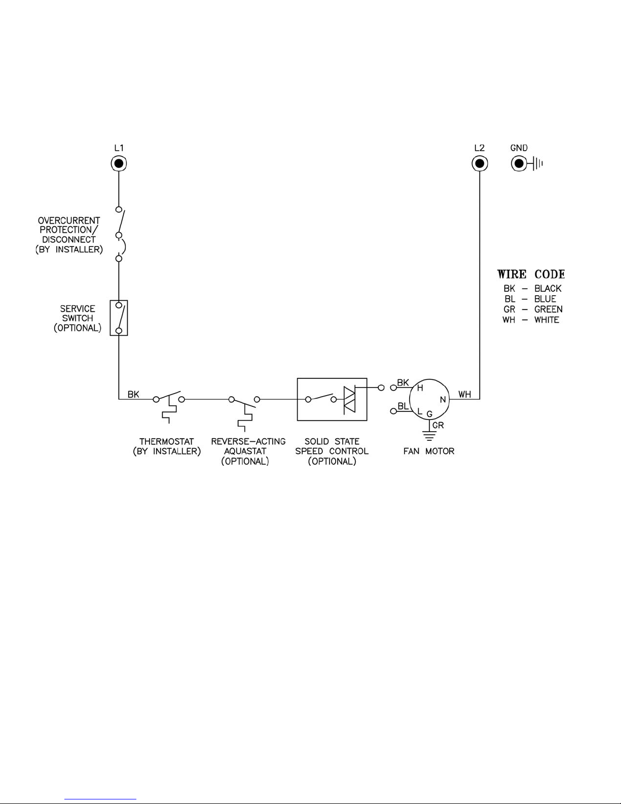
Figure 3: 115V / 60Hz / 1PH Wiring Schematic
6
Page 7
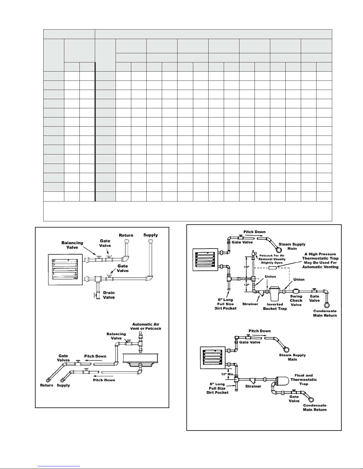
Table 1: Recommended Maximum Mounting Height
epyTlatnoziroH epyTlacitreV
ledoM
rebmuN
H S H S H S H S H S H S H S H S
81-HB971 24-VB117151118 913111822822882
42-HB981 95-VB3102813195261410182982853
33-HB0102 87-VB412291411162715111031103803
74-HB2152 59-VB614212611162715111031103803
36-HB4192 931-VB817242813123128131633163954
68-HB5113 161-VB1213821241533202410441040105
801-HB5123 391-VB3243133261935222514461442155
121-HB6133 212-VB5273335261935222514461442155
561-HB7143 742-VB6293436271640362812571253156
391-HB8173 972-VB0354730381355303120681063157
852-HB9104 333-VB0354730371355303120671063157
092-HB0244 583-VB0354630371355303120671063157
043-HB0264 005-VB7365447391562473624791473139
.tF-thgieH
ledoM
rebmuN
016-VB63453463913614145227------------
evuollatnozirohhtiW:SETON
rotcelfeDoN teJ-enoC enocnurT
.tF-thgieH .tF-thgieH .tF-thgieH .tF-thgieH .tF-thgieH .tF-thgieH .tF-thgieH
.)riagniretneF°06dnamaetS.isp2(
yaW-enO
srevuoL
yaW-owT
srevuoL
noitidnocdradnatstagnitareposretaehroferaseulaV.enalplacitrevehtmorf°03neposr
.noitisopdenepo-yllufriehtnisrotcelfedhtiweratejenocdnasrevuolyaw-owtrofsthgiehdetsiL
enoC-3
tatsomenA
enoC-4
tatsomenA
Horizontal Unit Heater Connected to
Overhead Hot Water Mains
Vertical Unit Heater Connected to
Overhead Hot Water Mains
Figure 4: Hot Water System Piping
Unit Heater Connection for High Pressure Steam
Unit Heater Connection for Low Pressure Steam - Open Grav-
ity or Vacuum Return System
Figure 5: Steam System Piping
7
Page 8

IV. OPERATION
A. PRIOR TO OPERATION
1. Check all electrical connections to assure they are
secure.
2. Check rigidity of unit mounting. Tighten all
fasteners, if necessary.
3. Inspect piping, strainers, traps, fi ttings, etc.
B. INITIAL START-UP
1. Set thermostat to lowest position.
2. Turn on power supply to unit.
3. Open return gate valve, and then open supply gate
valve to unit.
4. Raise thermostat setting to desired position.
5. Adjust louvers (if provided) for desired heat
distribution.
6. To insure proper sequence of operation, cycle unit
on and off a few times by raising and lowering
thermostat setting.
7. Check for proper rotation of fan. All fans must rotate
in a counterclockwise direction when viewed from
the back (BH) of the unit heater.
8
Page 9

V. MAINTENANCE
INSPECT REGULARLY
A.
Under average conditions, it is recommended that
unit heaters be inspected before every heating season
— more often in locations where air is contaminated
with corrosive fumes, dust, soot or oil spray. Check
for dirty, clogged coils, excessive vibration and loose
connections. Inspect piping, strainers, traps, fi ttings, etc.
B. MOTORS
1. Cleaning
Remove grease and dirt on motor during each
inspection or lubrication. Open frame motors should
be blown clean every heating season, or whenever
coils are cleaned, whichever is sooner.
2. Lubrication
Lubricate motor according to manufacturer’s
instructions located on the motor. When no motor
oiling instructions are on the motor, oil the motor
every two thousand hours of operation with SAE20
motor oil for units in normal applications. Adjust
oiling according to usage and atmosphere. Some
motors do not have oil fi ttings. These motors are
lubricated for long life and do not require further
lubrication.
3. Overload Protection
A change in line voltage higher or lower than motor
nameplate rating may cause overheating and serious
motor damage. Check plant voltage conditions.
A separate manual starter with thermal overload
protection device is recommended for those units
that do not have motors with built in overload
protection.
C. CASINGS
1. Cleaning
Periodic cleaning of casings is recommended to
remove dirt, grease and corrosive substances that
may injure fi nish. Rusted or corroded spots should
be cleaned and repainted.
2. General Inspection
Tighten fan guard and motor bracket. Check fan for
proper clearance, free rotation and fi rm connection
to shaft. When servicing is complete, tag unit to
indicate date of inspection, lubrication and cleaning.
GNINRAW
launamsihtniderevoctnempiuqeehT
dnadeniatniam,dellatsniebdluohs
.naicinhcetdeifilauqaybdecivres
ECITON
deifilauqlacolruoytcatnocecivresroF
rorotcartnocecivresdnanoitallatsni
.ynapmocytilituetairporppa
D. COILS
1. Cleaning
Clean coil at least once a year, more often under
unfavorable conditions. Unless coil is kept
reasonably free of dirt, lint and grease, its original
heating capacity will be reduced — possibly to a
serious degree, and motor damage may result.
Two commonly used cleaning methods are:
a. Loosen dirt by brushing fi ns on side where air
enters coil and then turn on fan to blow dirt from
unit.
b. Use high-pressure air hose to loosen dirt by
blowing from side where air leaves coil (side
adjacent to louvers on blow-through units (BH);
side adjacent to fan on draw-through units (BV)).
For thorough cleaning of coil, remove motor and
fan and spray a mild alkaline cleaning solution
over the coil. After a few minutes, follow by a
hot water rinse. (A steam gun can be used for
spraying cleaning solution and hot water.) Coils
subjected to corrosive fumes should be checked
and cleaned frequently.
2. Internal Corrosion Safeguards
Provide controlled water treatment -- don’t use
excess of boiler compounds. Contact your boiler
compound supplier for proper usage or the services
of a water treatment laboratory. Periodic internal
fl ushing of the coils is recommended in areas where
water supply is suspected of causing scale. Use an
alkaline-chelant solution and introduce it at the main
pump of the hydronic system. Flush thoroughly.
GNINRAW
sahcussdicalarenimrocinagronignisU
hguohtneve,dica)cirolhcordyh(citairum
,egamaderevesotdaelyam,detibihni
.egakaeldnanoisorrocgnidulcni
De-aerate boiler feed-water (particularly if large
amount of new water is used). Insure rapid continuous
and adequate condensate drainage by properly sized
and installed traps and piping. Check traps for sticking.
Clean strainers ahead of traps. (When traps don’t work,
condensate accumulates in unit heater coil; water
hammer results.) Adequately vent each unit. Use lowpressure steam when possible.
9
Page 10

VI. APPLICATION GUIDELINES
A. GENERAL GUIDELINES
1. The fi rst step in the design of a job is typically to
determine the heat loss. Refer to ASHRAE and
others for publications on the basic methodology
used in calculating the building or area’s heat loss.
Special attention should be paid to the building type
(architecturally) and application placement (area
use) in this procedure.
2. The second step is to decide the necessary
engineering data for design conditions such as CFM,
fi nal air temperature, quantity and location of units,
based on the specifi c Burnham Hydronics Unit
Heater model selected.
3. Burnham Hydronics steam/hot water unit heaters’
versatility offers a wide selection of outputs and
airfl ow allowing almost unlimited fl exibility in job
design.
4. Keep the following guidelines in mind when
designing any job using steam/hot water unit
heaters:
• Always direct airfl ow to regions of greatest heat
loss.
considering the nuisance of a loud unit. All units
were designed to minimize sound created by airfl ow
and motor operation by careful component selection
and inlet geometry. Sound Classifi cation Table 2
shows typical rooms and their corresponding sound
class rating.
Typical BH Unit Arrangement
• Use louvers for adjustment of throw length and
complete directional control of airfl ow.
• Mount units at the lowest practical and allowable
level.
• Select lower CFM models for lower installation
heights and heavily occupied areas. Select higher
CFM models for areas where higher installation is
required.
• More, smaller units will provide better heat
distribution than fewer larger units.
• Watch fi nal air temperatures on units mounted at
lower levels or in heavily occupied areas to ensure
that air is warm enough to avoid drafts being felt.
• Sound classifi cations: Burnham Hydronics Unit
Heaters provide exceptional heat output while
Table 2: Sound Class Ratings*
GNIDLIUBROMOORFOEPYT GNITARSSALCDNUOS
smoortseR,sreyoF,slatipsoH,seirarbiL,seciffO,sloohcS I
seitilicaFgniniDlaicremmoC,sesuohbulC,serotStnemtrapeD,smoorwohS II
sraB,smuisanmyG,serotSesuoheraW,seibboLegraL III
saerAnommoCmuidatS,spohSenihcaM,saerAgnippihS,seirotcaFllamS IIV-II
spohSnoitacirbaF,seirotcaFegraL IIV
*When placed in the paired room, the unit’s noise should be relatively comparable to the ambient sound level.
10
Page 11

B. STEAM PERFORMANCE DATA
Table 3: Steam Performance Data -- High Motor Speed
Performance Data at Standard Conditions of 2 lb. Steam and 60°F Entering Air
.xaM
ledoM
epyT
YREVILEDRIALACITREV YREVILEDRIALATNOZIROH
ledoM
rebmuN
81-HB000,8157II9 7100401520181
42-HB000,42001II9 8105408590152
33-HB000,33831II010203601590153
74-HB000,74691III215203700602194
36-HB000,36362III4192021150621166
68-HB000,68853III5113043103791198
801-HB000,801054III51230551526521111
121-HB000,121405III61335771517321621
561-HB000,561886VI71430052057121071
391-HB000,391408VI81730092078221002
852-HB000,8525701V 91040093029121762
092-HB000,0928021V 024400340101221003
043-HB000,0437141V 02640315569121253
24-VB000,24571II11
95-VB000,95642II31
87-VB000,87523II41
59-VB000,59693II61
931-VB000,931975III81
161-VB000,161176III12
391-VB000,391408VI32
212-VB000,212388VI52
742-VB000,7429201VI62
972-VB000,9723611V03
333-VB000,3338831V03
583-VB000,5834061IV03
005-VB000,0053802IV73
016-VB000,0162452IV63
.rH/UTB
.tF.qS
RDE
dnuoS
**ssalC
gnitnuoM
*)tf(thgieH
51
81
91
12
42
82
13
33
43
73
73
63
44
34
Table 4: Steam Performance Data -- Reduced Motor Speed
Performance Data at Standard Conditions of 2 lb. Steam and 60°F Entering Air
taeH
71
02
22
42
72
13
43
73
93
54
54
54
65
45
ATADRIA
tadaerpS
*thgieH.xaM
mfC
05997730134
11
31
41
61
81
12
32
52
62
03
03
03
73
63
051134911116
055129901118
5771631131199
00524821611441
00920941511761
00933461901002
00342181901912
03155081701652
00850402701882
00668691011543
06870391601893
097010942301815
053215432601136
teltuO
yticoleV
)mpF(
riAlaniF
.pmeT
)F°(
etasnednoC
rh/bl
* denepoyllufsedalb,rotcelfedtejenochtiwdeppiuqesepytlacitrev,enalplacitrevmorf°03neposrevuollatnozirohhtiwstinU
ledoM
epyT
YREVILEDRIALATNOZIROH
ledoM
rebmuN
81-HB008,4126I 9 2101359340151
42-HB007,9128I 9 3105355421112
33-HB001,72311I 014109459311192
74-HB005,83161II218156556432104
36-HB007,15612II411207807451145
68-HB005,07492II5122040107532137
801-HB006,88963II5132042100562119
121-HB002,99314II61325141075521301
561-HB003,531465III71420991006321931
391-HB003,851956III81620132596321461
.dlobninwohsera
.atadecnamrofrep
.rH/UTB
RDE
ATADRIA
dnuoS
.tF.qS
**ssalC
.snoitinifeDssalCdnuoSrof7egapeeS**
.xaM
gnitnuoM
*)tf(thgieH
taeH
tadaerpS
*thgieH.xaM mfC
teltuO
yticoleV
)mpF(
riAlaniF
.pmeT
)F°(
etasnednoC
rh/bl
yrosseccateltuolanoitiddarof12egapeesesaelP.srotcelfedtuohtiwstinurofsiataddaerps/thgiehgnitnuomdedlob-noN
11
Page 12

SELECTION PROCEDURE - STEAM APPLICATION
C.
Example 1:
GIVEN DESIGN CONDITIONS:
Unit Heater Model: BH-63
Steam Pressure: 10 lb
Entering Air Temperature: 70°F
APPLICATION PROCEDURE:
:yticapaC.1
utB
:etasnednoC.2
RTA
riAlaniF.3
:erutarepmeT
A
TAF
A
.4gnitnuoM.xaM
:thgieH
Example 2:
GIVEN DESIGN CONDITIONS:
Vertical Air Delivery requested
Heating Load: 100,000 Btu/hr
Entering Air Temperature: 50°F
Steam Pressure: 2 lb
utB=
A
S
TAF(=
S
TAE=
A
F°46.521=
HMM
A
utB=etaRetasnednoC
TAE-
S
RTA+
A
HMM=
S
=60.1x000,36= rh/utB087,66
A
5.259/087,66= rh/.bl11.07=
=701x)F°06-F°21(= F°46.55
=49.0xteef41= eef61.31 t
rotcaFyticapaCgnitaeHx
maetSfotaeHtnetaL/
rotcaFesiR.pmeTriAx)
°46.55+F°07= F
rotcaFnoitcerroCx
000,36 .3elbaTmorfrh/utB
si 5.259 .8elbaTmorf,.bl/utB
.dts sisnoitidnoc F°211 .3elbaTmorf
A
si 41 .3elbaTmorf,teef
49.0 .7elba
icnevigrof 60.1 .5elbaTmorf
siecnatsmucr
siecnatsmucricnevig 70.1 .6elbaTmorf
Tmorf
si36-HBnafoyticapacdradnatsehT
rotcafnoisrevnocyticapacgnitaehmaetS
.bl01tamaetsfotaehtnetalehT
ta36-HBnafoerutarepmetrialanifehT
rofrotcafnoisrevnocesirerutarepmetri
noitidnoc.dtstathgiehgnitnuom.xamehT
sirotcafnoitcerrocthgiehgnitnuomehT
APPLICATION PROCEDURE:
utB
:noitceleStinU.1
utB=
S
gnitaeHlautcA.2
:yticapaC
utBeblliw
A
12
A
=70.1/000,001= rh/utB854,39
utB=
S
=70.1x000,59= rh/utB056,101 .
tceleS.)snoitidnocdradnatsta( .59-VB
rotcaFyticapaCgnitaeH/
ehtteemlliwledom59-VBna,3elbaTmorF
foyticapacdetarstihtiwstnemeriuqergnitaeh
000,59 .snoitidnocdradnatst
snoitidnoclautcata59-VBnafoyticapacehT
rotcaFyticapaCgnitaeHx
arh/utB
rofrotcafnoisrevnocyticapacgnitaehmaetS
siecnatsmucricnevig 70.1 .5elbaTmorf
Page 13

D.
STEAM CALCULATION FORMULAS
1. Refer to Table 5:
a. To determine the heating capacity (Btu/hr) of a
unit heater at a steam pressure and/or entering
air temperature other than standard conditions of
2 lb. Steam and 60°F entering air temperature.
b. To fi nd actual unit heater capacity when
operating at non-standard (actual) conditions:
Btu
= BtuS x Heating Capacity Factor
A
c. To select a heater capacity based on standard
conditions to meet a heating capacity at nonstandard (actual) conditions:
BtuS = BtuA / Heating Capacity Factor
2. Refer to Table 6:
a. To determine the air temperature rise of a unit
heater at a steam pressure and/or entering air
temperature other than standard conditions of
2 lb. Steam, 60°F entering air temperature.
b. To fi nd actual air temperature rise of unit
heater when operating at non-standard (actual)
conditions:
ATRA = (FATS - EATS) x Air Temperature Rise
Factor
c. To fi nd actual fi nal air temperature of unit
heater when operating at non-standard (actual)
conditions:
FATA = EATA + ATR
A
3. Refer to Table 7:
To determine how non-standard steam pressures
(other than 2 lb.) affect mounting height.
Max. Mounting HeightA = Max. Mounting
HeightS x Correction Factor
4. Refer to Table 8:
To determine the rate of condensate production at
steam pressures other than 2 lb.
Condensate Rate = BtuA / Latent Heat of Steam
5. Terminology:
a. ATRA = Air temperature rise at non-standard
(actual) conditions
b. BtuA = Capacity at actual operating conditions
c. BtuS = Capacity at standard conditions (2 lb.
Steam, 60°F entering air temperature) from
Tables 3 and 4.
d. EATA = Entering air temperature at non-standard
actual) conditions
e. EATS = Entering air temperature at standard
conditions (60°F)
f. FATA = Final air temperature at non-standard
(actual) conditions
g. FATS = Final air temperature at standard
conditions from Tables 3 and 4.
h. Max. Mounting HeightA = Maximum mounting
height at actual conditions
i. Max. Mounting HeightS = Maximum mounting
height at standard conditions
13
Page 14

E.
STEAM CORRECTION FACTORS
Table 5: Steam Heating Capacity Conversion Factors
tinU
retaeH
sepyT
YREVILEDLACITREVYREVILEDLATNOZIROH
gniretnE
.pmeTriA
)F°(
01-45.195.146.137.108.168.179.160.231.202.262.282.213.263.214.215.206.2
054.105.155.146.117.177.178.169.140.290.261.281.212.262.213.214.205.2
0173.114.164.155.116.186.187.168.149.100.260.290.211.261.202.213.204.2
0272.123.173.164.135.185.186.177.158.109.169.199.120.260.211.212.203.2
0391.142.192.183.144.105.106.186.167.118.178.109.139.179.120.211.202.2
0411.161.112.192.143.124.115.106.176.137.187.118.148.188.139.120.211.2
0530.180.131.112.182.133.134.115.185.146.107.127.157.197.148.139.120.2
0669.000.150.131.191.152.153.134.105.165.116.146.166.117.157.148.139.1
0788.039.079.060.121.171.172.153.124.174.135.155.185.126.166.167.148.1
0818.058.009.089.040.101.191.172.143.193.154.174.105.145.185.186.167.1
0947.087.038.019.079.020.121.191.162.113.173.104.124.164.105.195.176.1
00176.017.067.048.009.059.040.121.191.142.192.123.143.183.124.115.195.1
01-94.125.185.146.107.157.138.109.169.120.270.201.211.251.291.272.243.2
014.154.105.175.126.176.157.128.178.149.199.120.240.280.211.291.262.2
0133.173.124.194.155.106.186.157.118.178.129.149.169.100.230.211.281.2
0252.192.143.114.174.125.116.186.147.197.148.168.188.129.159.199.101.2
0381.122.172.143.104.154.135.116.176.127.167.197.108.148.188.119.130.2
0411.151.102.172.123.173.164.135.195.146.196.117.137.177.108.188.159.1
0530.170.121.191.152.103.193.164.125.175.126.146.166.196.137.118.188.1
0669.000.150.121.181.132.123.193.154.105.155.175.195.126.166.147.118.1
0709.039.089.050.111.161.152.123.183.134.174.194.115.155.195.176.147.1
0838.068.019.089.040.190.181.152.113.163.104.124.144.184.125.106.176.1
0967.008.058.019.079.020.111.181.142.192.133.163.183.114.154.135.106.1
001
0 2 5 01 51 02 03 04 05 06 07 57 08 09 001 521 051
96.037.087.058.009.069.040.111.171.122.172.192.113.143.183.164.135.1
)GISP(ERUSSERPMAETS
14
Page 15

Table 6: Air Temperature Rise Conversion Factors
tinU
retaeH
sepyT
YREVILEDLACITREVYREVILEDLATNOZIROH
gniretnE
.pmeTriA
)F°(
01-33.183.134.105.165.116.107.187.148.119.159.179.100.240.280.271.252.2
082.133.183.154.115.165.156.137.197.168.119.139.159.100.240.231.212.2
0142.172.133.104.164.125.106.186.147.118.168.198.119.159.199.190.271.2
0271.122.172.153.124.164.155.126.196.157.118.148.168.109.159.140.221.2
03
0470.111.161.142.101.163.164.145.106.166.117.147.167.118.158.149.130.2
0510.160.111.191.142.103.104.184.155.116.166.196.127.157.197.198.189.1
0669.000.150.131.191.152.153.134.105.165.116.146.166.107.157.148.139.1
0709.049.000.170.141.191.192.183.154.105.165.185.116.156.196.197.178.1
0848.088.039.020.180.141.142.123.193.154.115.135.165.106.146.147.138.1
0987.038.088.059.020.180.181.162.133.104.154.174.194.145.195.186.177.1
00127.067.028.009.079.020.121.112.182.133.193.124.144.194.135.136.117.1
01-63.114.164.145.116.176.177.158.129.199.150.280.201.251.291.292.293.2
013.153.104.184.155.116.117.197.168.139.199.120.240.290.241.242.233.2
0152.192.153.134.194.155.156.147.118.188.149.169.199.140.280.281.272.2
0291.142.192.173.144.105.106.186.157.128.188.119.139.100.220.221.222.2
0331.181.132.113.183.144.145.126.196.167.128.158.178.129.179.170.261.2
0480.121.171.152.123.183.184.165.146.107.167.197.118.168.119.110.201.2
0520.160.121.102.162.123.124.115.185.156.107.137.157.108.158.159.140.2
0669.000.160.141.102.162.163.154.125.185.156.176.107.147.197.198.199.1
0709.049.000.180.141.102.103.193.164.135.195.126.146.196.137.138.139.1
0848.088.049.020.190.151.152.133.104.174.135.165.185.136.176.177.178.1
0987.028.088.069.020.180.181.172.143.114.174.105.125.175.116.117.118.1
001
0 2 5 01 51 02 03 04 05 06 07 57 08 09 001 521 051
21.171.112.192.163.114.115.185.156.117.167.197.128.168.198.199.170.2
27.067.028.098.079.020.121.112.182.153.114.134.164.115.155.156.157.1
)GISP(ERUSSERPMAETS
Table 7: Steam Unit Heater Mounting Height Correction Factors
2501510203040506070809001521051571
)GISP(erusserPmaetS
rotcaFnoitcerroC
00.179.049.029.098.068.048.028.008.097.077.067.057.047.027.017.0
15
Page 16

Table 8: Properties of Steam
eguaG
erusserP
)GISP(
00.2123.079
25.8122.669 639.1829.229 277.7130.698 2114.5439.378
44.4224.269 833.4821.129 473.9138.498 5112.7435.278
52.7226.069 047.6823.919 679.0235.398 8119.8430.178
68.9228.859 240.9826.719 874.2233.298 1217.0536.968
88.4326.559 443.1929.519 089.3231.198 4214.2532.868
014.9325.259 645.3923.419 284.5239.988 5219.2538.768
217.3426.949 846.5927.219 489.6238.888 7210.4539.668
418.7428.649 057.7922.119 684.8236.788 0317.5535.568
616.1522.449 257.9927.909 888.9235.688 3313.7531.468
813.5527.149 457.1032.809 092.1334.588 6319.8539.268
028.8523.939 656.3037.609 295.2333.488 9314.0635.168
221.2629.639 855.5033.509 499.3332.388 2410.2633.068
423.5627.439 063.7039.309 692.5331.288 5415.3630.958
623.8625.239 261.9035.209 896.6331.188 0519.5639.658
823.1725.039 469.0132.109 0019.7330.088 5714.7738.648
031.4725.829 666.2139.998 3018.9335.878 0029.7832.738
238.6726.629 864.4136.898 6017.1439.678 5223.7935.828
pmeT
)F°(
taeHtnetaL
).bl/utB(
eguaG
erusserP
)GISP(
43
pmeT
)F°(
4.9727.429 070.6133.798 9016.3434.578
taeHtnetaL
).bl/utB(
eguaG
erusserP
)GISP(
pmeT
)F°(
taeHtnetaL
).bl/utB(
eguaG
erusserP
)GISP(
pmeT
)F°(
taeHtnetaL
).bl/utB(
16
Page 17

F. HOT WATER PERFORMANCE DATA (at Standard Conditiions of 200°F Entering Water, 60°F Entering Air and
20°F Water T emperatur e Drop)
Table 9: Hot Water Performance Data -- High Motor Speed
ATADRETAW ATADRIA
erusserP
ledoM
epyT
YREVILEDRIALACITREV YREVILEDRIALATNOZIROH
ledoM
rebmuN .rH/UTB
81-HB000,313.194.00.5/3.0II9 8100400509
42-HB003,717.138.00.5/3.0II010205407569
33-HB005,425.221.00.01/4.0II112203659469
74-HB008,334.312.00.01/4.0III3162037085301
36-HB005,647.474.00.51/5.0III5103021109589
68-HB009,162.697.00.51/5.0III61130431017301
801-HB000,181.858.00.02/5.0III61330551506801
121-HB000,090.940.10.02/7.0III71635771096701
561-HB000,3313.3184.20.03/0.2VI81830052537901
391-HB000,6516.5153.30.03/0.2VI91040092058011
852-HB000,8918.9145.30.04/5.2V02240093598701
092-HB000,4224.2254.40.04/5.2V12640034099801
043-HB000,3723.7
24-VB005,031.390.00.01/5.0II11
95-VB003,445.481.00.51/8.0II41
87-VB005,850.634.00.02/0.1II51
59-VB000,172.716.00.52/3.1II71
931-VB000,1113.1148.00.03/0.1III81
161-VB008,8211.3111.10.04/3.1III22
391-VB007,2415.4118.00.05/5.1VI42
212-VB000,9511.6189.00.06/0.2VI52
742-VB000,7919.9156.10.06/0.2VI72
972-VB000,0222.2210.20.57/3.2V13
333-VB000,5627.6272.10.57/8.2V03
583-VB000,8031.1386.10.57/3.3IV33
005-VB000,3049.0423.20.001/0.3IV04
016-VB000,9543.6424.20.001/0.6IV93
MPG
242.30.05/5.2V22050315549901
porD
fo.tf(
)retaw
xaM/niM
MPG
dnuoS
**ssalC
.xaM
gnitnuoM
*).tf(thgieH
51
91
12
32
52
03
33
53
63
93
83
04
84
74
taeH
tadaerpS
*thgieH.xaM mfC
71
12
32
52
82
33
63
73
04
74
64
94
06
85
05967719
11
51
61
71
91
12
42
52
72
13
03
33
04
04
051104979
055109969
5771231199
00521821301
00928841301
0093046159
0034908169
0315308179
0085730279
0066669199
0687829179
09701784249
05321343279
teltuO
yticoleV
)mpF(
riAlaniF
.pmeT
)F°(
Table 10: Hot Water Performance Data -- Reduced Motor Speed
ledoM
epyT
YREVILEDRIALATNOZIROH
* denepoyllufsedalb,rotcelfedtejenochtiwdeppiuqesepytlacitrev,enalplacitrevmorf°03neposrevuollatnozirohhtiwstinU
ledoM
rebmuN
81-HB066,013.194.0I9 3101309329
42-HB681,417.138.1I 014105305489
33-HB090,025.221.0I 116109409389
74-HB617,724.312.0II3181565554501
36-HB031,837.474.0II5112078064101
68-HB857,052.697.0II61220401055501
801-HB024,661.858.0II61320421584011
121-HB008,370.940.1II71625141555801
561-HB060,9013.3184.2III81720991095111
391-HB029,7216.5153.3III91820132086111
.dlobninwohsera
.atadecnamrofrep
.rH/UTB
ATADRETAW ATADRIA
erusserP
porD
MPG
.snoitinifeDssalCdnuoSrof7egapeeS**
fo.tf(
)retaw
dnuoS
**ssalC
.xaM
gnitnuoM
*).tf(thgieH
taeH
tadaerpS
*thgieH.xaM mfC
teltuO
yticoleV
)mpF(
riAlaniF
.pmeT
)F°(
yrosseccateltuolanoitiddarof12egapeesesaelP.srotcelfedtuohtiwstinurofsiataddaerps/thgiehgnitnuomdedlob-noN
17
Page 18

SELECTION PROCEDURE - HOT WATER APPLICATION
G.
Example 1:
GIVEN DESIGN CONDITIONS:
Unit Heater Model: BV-59, Entering Water Temperature: 250°F, Entering Air Temperature: 70°F
APPLICATION PROCEDURE:
:yticapaC.1
utB
:etaRwolFretaW.2
riAlaniF.3
:erutarepmeT
.4gnitnuoM.xaM
DTW
:thgieH
gnitnuoM.xaM.5
:thgieH
Example 2:
GIVEN DESIGN CONDITIONS:
Horizontal Air Delivery requested, Heating Load: 120,000 Btu/hr, Entering Air Temp.: 50°F, Entering Water Temp.:
180°F
utB=
A
S
=272.1x003,44= rh/utB053,65
rotcaFyticapaCgnitaeHx
si95-VBnafoyticapacdradnatsehT
003,44 .9elbaTmorfrh/utB
rotcafnoisrevnocyticapacgnitaehmaetS
siecnatsmucricnevigrof 272.1 .11elbaTmorf
dradnatssaemaS
anopudesabsi95-VBnoyticapacdradnatsehT
foetarwolfretaw 5.4 .9elbaTmorf,MPG
TAF
TAE=
A
A
mfCx675(
utB/)
S
TAF
A
utB=
A
A
=)5.4x084( F°90.62
HMM
A
A
HMM=
S
=68.0xteef41= teef0.21
TAE+064([+
/)
A
])1-
/)07+064([+F°07=
=])1-053,65/)0511x675( F°911
/053,65=)AGx084(/
rotcaFnoitcerroCx
si95-VBnafowolfriadradnatsehT 0511 ,MFC
.9elbaTmorf
anopudesabsi95-VBnoyticapacdradnatsehT
foetarwolfretaw 5.4 .9elbaTmorf,MPG
noitidnocdradnatstathgiehgnitnuom.xamehT
si 41 .9elbaTmorf,teef
sirotcafnoitcerrocthgiehgnitnuomehT
68.0 .41elbaTmorf
APPLICATION PROCEDURE:
:noitceleStinU.1
gnitaeHlautcA.2
:yticapaC
riAlaniF.3
:erutarepmeT
.4erutarepmeTretaW
:porD
gnitnuoM.xaM.5
:thgieH
18
utB
utB=
S
A
=049.0/000,021= rh/utB066,721
rotcaFyticapaCgnitaeHx
rofrotcafnoisrevnocyticapacgnitaehretaWtoH
siecnatsmucricnevig 049.0 .11elbaTmorf
tceleS.)snoitidnocdradnatsta( .561-HB
utBeblliwsnoitidnoc
lautcata561-HBnafoyticapacehT
utB=
A
X
gnitaeHx
=049.0x000,331=rotcaFyticapaC
rofrotcafnoisrevnocyticapacgnitaehretaWtoH
siecnatsmucricnevig 049.0 .11elbaTmorf
rh/utB020,521
TAF
TAE=
A
A
mfCx675(
S
DTW
utB=
A
A
HMM
HMM=
A
=80.1x81= teef4.91
S
TAE+064([+
=])0052x675(/)020,521( F°49
MPGx084(/
)
A
=)3.31x084(/020,521= °5.91 F
tcerroCx rotcaFnoi
utB(x)
A
/)
A
x05+064([x05=])
siecnatsmucricnevigrofmfC 0052 morf
.9elbaT
MPG
A
.9elbaT
siecnatsmucricnevigrof 3.31 morf
sirotcafnoitcerrocthgiehgnitnuomehT 80.1
.41elbaTmorf
Page 19

H.
HOT WATER CALCULATION FORMULAS
1. Refer to Table 11:
a. To determine the heating capacity (Btu/hr) of a
unit heater at a water temperature and/or entering
air temperature other than standard conditions of
200°F entering water temperature, 60°F entering
air temperature.
b. To fi nd actual unit heater capacity when
operating at non-standard (actual) conditions:
Btu
= BtuS x Heating Capacity Factor
A
c. To select a heater capacity based on standard
conditions to meet a heating capacity at nonstandard (actual) conditions:
BtuS = BtuA / Heating Capacity Factor
2. Refer to Table 12:
a. To determine how water temperature drop affects
heat capacity in Btu, water fl ow rate is in GPM
and pressure drop in feet of water. These factors
should be applied to the values at actual entering
water and air temperature conditions.
b. To fi nd actual unit heater capacity or fl ow rate
or pressure drop when operating at non-standard
(actual) conditions:
BtuA = BtuS x Btu Correction Factor
GPMA = GPMS x GPM Correction Factor
WPDA = WPDS x WPD Correction Factor
c. To select a heater capacity based on standard
conditions to meet a heating capacity at nonstandard (actual) conditions:
BtuS = BtuA / Btu Correction Factor
d. Other useful formulas:
FATA = EATA + [(460 + EATA) x (BtuA) / (576 x
CfmS)] For BH units only
FATA = EATA + [(460 + EATA) / (576 x CfmS /
BtuA)-1)] For BV Units only
3. Refer to Table 13:
a. To determine how glycol solutions affect heater
capacity. These factors should be applied to the
heater capacity at actual entering water and air
temperature conditions.
b. To fi nd actual unit heater capacity when operated
with glycol solution:
Btu
= BtuS (or BtuA) x Glycol Correction
AG
Factor
c. To select a heater capacity based on standard
conditions to meet a heating capacity with glycol
solution:
Btu
(or BtuA) = BtuAG / Glycol Correction
S
Factor
4. Refer to Table 14:
To determine how water temperatures other than
200°F affect mounting height of unit.
Max. Mounting HeightA = Max. Mounting
HeightS x Correction Factor
5. Terminology:
a. BtuA = Capacity at non-standard (actual)
conditions
b. BtuAG = Capacity with Glycol solution
c. BtuS = Capacity at standard conditions (200°F
entering air temperature, 60°F entering air
temperature) from Tables 9 and 10
d. CfmS = Unit airfl ow as found in Tables 9 and 10
e. EATA = Entering air temperature at actual
conditions
f. FATA = Final air temperature at actual conditions
g. GPMA = Water fl ow rate at actual conditions in
GPM
h. GPMS = Flow rate at standard conditions (200°F
entering water temperature, 60°F entering air
temperature) from Tables 9 and 10
i. Max. Mounting HeightA = Maximum mounting
height at actual conditions
j. Max. Mounting HeightS = Maximum mounting
height at standard conditions
k. WPDA = Water pressure drop at non-standard
(actual) conditions
l. WPDS = Water pressure drop at standard
conditions (200°F entering water temperature,
60°F entering air temperature) from Tables 9 and
10
19
Page 20

I. HOT WATER CORRECTION FACTORS
Table 11: Hot Water Heating Capacity Conversion Factors
riAgniretnE
)F°(.pmeT
001
011
021
031
041
051
061
071
081
091
002
012
022
032
042
052
062
072
082
092
003
0 01 02 03 04 05 06 07 08 09 001
967.0386.0995.0815.0934.0163.0682.0212.0041.0960.0000.0
648.0957.0476.0295.0215.0434.0753.0382.0012.0831.0860.0
329.0538.0947.0666.0585.0605.0924.0353.0972.0702.0731.0
000.1119.0428.0047.0856.0875.0005.0424.0943.0672.0502.0
770.1789.0998.0418.0137.0156.0175.0494.0914.0543.0372.0
451.1360.1479.0888.0508.0327.0346.0565.0984.0414.0243.0
132.1931.1940.1269.0878.0597.0417.0636.0955.0384.0014.0
803.1512.1421.1630.1059.0768.0687.0607.0926.0255.0874.0
583.1192.1991.1011.1420.1049.0758.0777.0996.0126.0745.0
294.1763.1472.1481.1790.1210.1929.0848.0867.0096.0516.0
935.1344.1943.1852.1071.1480.1000.1819.0838.0957.0486.0
516.1915.1424.1233.1342.1751.1170.1989.0809.0828.0257.0
269.1495.1994.1604.1213.1922.1341.1060.1879.0798.0028.0
967.1076.1375.1084.1093.1103.1142.1031.1840.1669.0988.0
648.1647.1946.1455.1364.1373.1682.1102.1811.1530.1759.0
329.1228.1327.1826.1635.1644.1753.1272.1881.1401.1520.1
000.2898.1897.1207.1906.1815.1924.1243.1752.1371.1490.1
770.2479.1378.1677.1286.1095.1005.1314.1723.1242.1261.1
451.2050.2849.1058.1557.1366.1175.1384.1793.1113.1032.1
132.2621.2320.2429.1928.1437.1346.1455.1764.1083.1003.1
803.2202.2890.2899.1209.1708.1417.1526.1735.1944.1763.1
)F°(ERUTAREPMETRIAGNIRETNE
Table 12: Correction Factors for Varying Water Temperature Drop*
)F°(,porDerutarepmeTretaW
rotcaFnoitcerroCutB
rotcaFnoitcerroCMPG
rotcaFnoitcerroCDPW
5 01 51 02 52 03 53 04 54 05 55 06
32.131.160.100.159.009.068.028.087.027.096.076.0
46.412.204.100.167.016.005.024.063.003.062.032.0
42.7123.458.100.116.014.003.022.081.041.021.011.0
Table 13: Ethylene Glycol Correction Factors**
)F°(erutarepmeTnoituloS
001
051
002
052
%02 %03 %04 %05 %06 %07 %08
99.069.039.098.058.018.067.0
99.069.049.009.078.038.087.0
99.079.049.029.088.058.018.0
89.069.049.029.098.068.028.0
Table 14: Hot Water Unit Heater Mounting Height Correction Factors***
041 051 061 071 081 091 002 012 022 032 042 052 062 072 082 092 003
.snoitidnocerutarepmetriaF°06dnaretawgniretneF°002dradnatsrofylnodilavsrotcafnoitcerrocporderutarepmetretaW*
%NOITULOSLOCYLGENELYHTE
.59.0ybrotcafnoitcerroclocylGenelyhtEylpitlum,rotcafnoitcerrocnoituloslocylGenelyporProF**
F°,ERUTAREPMETRETAWGNIRETNE
noitcerroC
rotcaF
33.152.191.131.180.140.100.179.049.019.098.068.048.028.008.087.077.0
20
.F°07otF°05morfgnignarerutarepmetriagniretnehtiwesuroferasrotcaF***
Page 21

VII. OPTIONS, ACCESSORIES AND CONTROL SEQUENCES
A. FIELD INSTALLED OPTIONS FOR HORIZONTAL AND VERTICAL MODELS
.oNtraP noitpircseD
PO-907BtatsomrehT .V772/V521@A22F°09otF°05egnaRtatsomrehTgnitaeHegatloVeniL
PO-017B
PO-117BtatsauqA
PO-217B
PO-317BdrauGtatsomrehT
PO-417BtiKregnaHepiP .dordedaerhtfodaetsniepipdedaerhtybgniliecmorfdednepsusebottinuwollA
gniwolloFotrefeR
elbaT
PO-617BtcennocsiD .noitareponaffolortnocffo/nowollatcennocsiddetnuoMllaW
.oNtraP noitpircseD
10-SMB420HB,810HB:esuFA18.0htiw
20-SMB740HB,330HB:esuFA98.0htiw
30-SMB
40-SMB121HB,801HB:esuFA9.1htiw
50-SMB
60-SMB
70-SMB
80-SMB 212VB,391VB,161VB,931VB,043HB,092HB:esuFA5.5htiw
90-SMB
01-SMB
foorP-noisolpxE
tatsomrehT
rellortnoCdeepS
)deepselbairaV(
retratSlaunaM
uoMllaW
391HB:esuFA4.3htiw
852HB:esuFA5.4htiw
333VB:esuFA6.01htiw
epsdetnuoMllaW
.erutarepmet
950VB,240VB,680HB,360HB:esuFA6.1htiw
590VB,870VB,561HB:esuFA1.3htiw
972VB,742VB:esuFA3.7htiw
.V032@A5.6,V511@A2.01egnarF°48otF°64
.dehcaersierutarepmetretawdenimretederp
.852-HBurht81-HBrofylnoelbaliava,emulovwolfria
sretratSlaunaMdetnuoMllaW
alitnurotomehtyaledlliwtI.F°042otF°001egnaRtatsauqAdetnuoMecafruS
gnillortnoc,deepsnaffotnemtsujdaetinifnietomerswollarellortnocde
tesfotnemtsujdadetnawnuretedotsyekdnakcolhtiwdrauggnikcolcitsalpraelC
ffo/noetomerrofnoitcetorpdaolrevolamrehthtiwretratshctiwselggotdetn
.daol%521otputinustcetorptahtdaolrevodesufahtiwsemocretratS.naffolortnoc
B. CONTROL SEQUENCES
The following control sequence descriptions are
commonplace for steam/hot water horizontal and
vertical air delivery unit heaters.
1. Intermittent Fan Operation - Intermittent Hot/Cold
Coil
a. When a thermostat calls for heat, the motor is
energized. At the same time, a valve is opened
allowing the heating fl uid to enter the unit heater.
b. Placing an aquastat to the supply or return
piping will prevent motor operation until coil is
properly heated to avoid the delivery of cold air.
c. After thermostat is satisfi ed, motor is de-
energized.
2. Intermittent Fan Operation - Hot Coil
a. When a thermostat calls for heat, the motor is
energized.
b. The heating fl uid is continuously supplied to the
unit heater, even with the motor off.
c. After thermostat is satisfi ed, motor is de-
energized.
3. Continuous Fan Operation - Intermittent Hot/Cold
Coil
a. When a thermostat calls for heat, a valve opens,
allowing the heating fl uid to enter the unit heater.
b. After the thermostat is satisfi ed, the valve closes.
c. The fan runs continuously.
C. FIELD INSTALLED OPTIONS FOR
HORIZONTAL MODELS ONLY
.oNtraP noitpircseD
10-A7BsedalBresuffiD42-HB/81-HB
20-A7BsedalBresuffiD74-HB/33-HB
30-A7BsedalBresuffiD68-HB/36-HB
40-A7B121-HB/801-HBsedalBresuffiD
50-A7B
60-A7BsedalBresuffiD852-HB
70-A7B
80-A7B
092-HBsedalBresuffiD
043-HBsedalBresuffiD
391-HB/561-HBsedalBresuffiD
21
Page 22

D.
FIELD INSTALLED OPTIONS FOR VERTICAL MODELS ONLY
teJ-enoC
oNtraP
10-JCVB
20-JCVB
30-JCVB
40-JCVB
50-JCVB
60-JCVB
70-JCVB
80-JCVB
enocnurT .tej-enocahtiwelbissopnahtaeraregralagnirevocmaertsriadaorbarofswollaenocnurtehT
oNtraP
10-CTVB
20-CTVB
30-CTVB
40-CTVB
revuoLyaW-enO .riafoegrahcsidlanoitceridenoarofswollarevuolyaw-enoehT
oNtraP
10-L1VB
20-L1VB
30-L1VB
40-L1VB
50-L1VB
60-L1VB
70-L1VB
80-L1VB016-VRrevuoLyaW-enO
revuoLyaW-owT .riafoegrahcsidlanoitceridenoarofswollarevuolyaw-owtehT
oNtraP
10-L2VB
20-L2VB
30-L2VB
40-L2VB
50-L2VB
60-L2VB
70-L2VB
80-L2VB
tatsomenAenoC-3 .enocnurtehthtiwelbissopnahtaeraregralagnirevocmaertsrianevenarofswollatatsomenaenoc-3ehT
oNtraP
10-A3VB
20-A3VB
30-A3VB
40-A3VB
50-A3VB
60-A3VB
70-A3VB
80-A3VB
tatsomenAenoC-4
oNtraP
10-A4VB
20-A4VB
30-A4VB
40-A4VB
50-A4VB
60-A4VB
70-A4VB
80-A4VB
enocnurT59,87,95,24-VR
enocnurT212,391,161,931-VR
enocnurT583,333,972,742-VR
ocnurT016,005-VR
en
noitpircseD
95,24-VRteJenoC
59,87-VRteJenoC
161,931-VRteJenoC
212,391-VRteJenoC
97
2,742-VRteJenoC
583,333-VRteJenoC
005-VRteJenoC
016-VRteJenoC
noitpircseD
noitpircseD
VRrevuoLyaW-enO
005-VRrevuoLyaW-enO
noitpircseD
VRrevuoLyaW-owT
005-VRrevuoLyaW-owT
016-VRrevuoLyaW-owT
noitpircseD
005-VRtatsomenAenoC-3
016-VRtatsomenAenoC-3
.tasomena
noitpircseD
005-VRtatsomenAenoC-4
016-VRtatsomenAenoC-4
.aeraregralarevocnactahtmaerts
95,24-VRrevuoLyaW-enO
59,87-VRrevuoLyaW-enO
161,931-VRrevuoLyaW-enO
212,391-
972,742-VRrevuoLyaW-enO
583,333-VRrevuoLyaW-enO
95,24-VRrevuoLyaW-owT
59,87-VRrevuoLyaW-owT
161,931-VRrevuoLyaW-owT
212,391-
972,742-VRrevuoLyaW-owT
583,333-VRrevuoLyaW-owT
95,24-VRtatsomenAenoC-3
59,87-VRtatsomenAenoC-3
161,931-VRtatsomenAenoC-3
2,391-VRtatsomenAenoC-3
21
972,742-VRtatsomenAenoC-3
583,333-VRtatsomenAenoC-3
95,24-VRtatsomenAenoC-4
59,87-VRtatsomenAenoC-4
161,931-VRtatsomenAenoC-4
2,391-VRtatsomenAenoC-4
21
972,742-VRtatsomenAenoC-4
583,333-VRtatsomenAenoC-4
denedaorbaotmaertsyticolevhgihtceridamorfdetsujdaebotriadegrahcsids'tinuehtswollatej-enocehT
enoc-3ehthtiwelbissopnahtaeraregralagnirevocmaertsrianevenarofswollatatsomenaenoc-4ehT
22
Page 23

Table 15: Vertical Air Outlet Accessory Dimensions*
teJenoC enocnurT srevuoL tatsomenAenoC-3 tatsomenAenoC-4
ledoM L T M X P Z N AA N EE
95-VB/24-VB
59-VB/87-VB
161-VB/931-VB
212-VB/391-VB
972-VB/742-VB
583-VB/333-VB
016-VB/005-VB
2/1-6 2/1-61 01 52 2/1-6 2/1-61 2/1-21 2/1-22 41 52
2/1-6 2/1-81 01 52 2/1-6 2/1-81 2/1-21 2/1-42 41 72
8 2/1-02 21 92 8 2/1-02 41 2/1-62 2/1-51 92
8 2/1-22 21 92 8 2/1-22 41 2/1-82 2/1-51 13
9 2/1-42 41 33 9 2/1-42 51 2/1-03 2/1-61 33
9 2/1-62 41 33 9 2/1-62 51 2/1-23 2/1-61 53
01 2/1-03 81 73 01 2/1-03 61 2/1-63 2/1-71 93
.sehcninisnoisnemidllA*
23
Page 24

Table 16: Vertical Air Outlet Accessory Maximum Height and Spread
123
.1 nisrotcelfedrofnwohsatad,tej-enocrosrevuolroF.snoitidnocerutarepmetriagniretneF°06,maetS.bl2dradnatsrofnwohsataD
.3
yaW-enO
teJenoC enocnurT
ledoM
H S H S H S H S H S H S
24-VB
95-VB
87-VB
59-VB
931-VB
161-VB
391-VB
212-VB
742-VB
972-VB
333-VB
583-VB
005-VB
016-VB
.noitisopdenepo-ylluf
.teefnisnoisnemidllA
dradnatS dradnatS dradnatS dradnatS dradnatS dradnatS
51 11 8 91 31 11 8 22 8 22 8 82
81 31 9 52 61 41 01 82 9 82 8 53
91 41 11
12 61 11 62 71 51 11 03 11 03 8 03
42 81 31
82 12 41 53 32 02 41 04 41 04 01 05
13 32 61
33 52 61 93 52 22 51 44 61 44 21 55
43 62 71
73 03 81 35 53 03 12 06 81 06 31 57
73 03
63 03 71 35 53 03 12 06 71 06 31 57
44 73 91
34 63 91 36 14 14 52 27 --- --- --- ---
.41elbaTnirotcafnoitcerroc
1
7
62
23 12 81
93
64
35 53
56
tlum,retawtohrofdaerpsdnathgiehgnitnuomroF.2
71 51 11 03 11 03
52
03 62 81 25
24 73 62 47
srevuoL
22
03 12 06
htoerutarepmetretawgniretneroF.erutarepmetretawgniretne
31 63
51 44
yaW-owT
srevuoL
31
61
71
71
91
enoC-3
tatsomenA
63 9
44 21
25 31
06 31
47 31
.7elbaTnirotcafnoitcerrocehtybeulavehtylpitlum,.bl2nahtrehtoerusserpmaetstadaerps/thgiehgnitnuomroF
enoC-4
tatsomenA
8 03
54
55
56
57
39
F°002tadaerpsdnathgiehgnitnuomehtetamixorppaot60.1ybevobaeulavehtylpi
ehtylpitlumnehtdna60.1ybevobaeulavehtylpitlum,F°002nahtre
Cone-Jet
Truncone
Anemo-
24
Lou-
No Defl ector
Page 25

VIII. DIMENSIONAL DATA
A. BH DIMENSIONAL DATA
Table 17: Model BH Dimensions
ledoM A B C D E F G H *H
81-HB
42-HB
33-HB
74-HB
36-HB
68-HB
801-HB
121-HB
561-HB
391-HB
852-HB
092-HB
043-HB
4/3-41 4/3-61 61/7-7 2/1-4 4/3-21 8/1-4 61/9-5 01 A/N 4/3 9 81
4/3-41 4/3-61 61/7-7 2/1-4 4/3-21 8/1-4 61/9-5 01 A/N 4/3 9 91
8/7-81 4/3-61 61/7-7 4/3-4 4/3-21 8/1-4 61/31-5 61 A/N 4/3 21 53
8/7-81 4/3-61 61/7-7 4/3-4 4/3-21 8/1-4 61/31-5 61 A/N 4/3 21 63
8/7-81 4/3-22 61/7-8 4/3-4 4/3-71 8/1-4 7 61 A/N 4/3 41 15
8/7-81 4/3-22 61/7-8 4/3-4 4/3-71 8/1-4 7 61 A/N 4/3 41 25
61/51-62 8/7-52 2/1-9 4/1-6 4/3-42 2/1-3 4/1-6 A/N 2 2/1-1 81 67
61/51-62 8/7-52 2/1-9 4/1-6 4/3-42 2/1-3 4/1-6 A/N 2 2/1-1 81 77
61/51-62 8/7-13 01 4/1-6 4/3-03 2/1-3 4/1-6 A/N 2 2/1-1 02 59
61/51-62 8/7-13 01 4/1-6 4/3-03 2/1-3 4/1-6 A/N 2 2/1-1 02 69
61/51-23 61/31-04 11 4/1-6 61/11-93 2/1-3 4/1-6 A/N 2 2 22 561
61/51-23 61/31-04 11 4/1-6 61/11-93 2/1-3 4/1-6 A/N 2 2 22 761
61/51-83 61/31-04 21 4/1-6 61/11-93 2/1-3 4/1-8 A/N 2 2 42 281
.sehcninisnoisnemidllA*
TPNelaM
snoitcennoC
.snoitcennocepipTPNelamefedisevah68-HBurht81-HB**
.snoitcennocepipTPNelammottobdnapotevah043-HBurht801-HB
naF
retemaiD
.xorppA
pihS
thgieW
25
Page 26

BV DIMENSIONAL DATA
B.
Table 18: Model BV Dimensions*
ledoM A B C D E F G H I
95-VB/24-VB
59-VB/87-VB
005-VB
016-VB
32 8/3-6 21 21 8/1-3 51 4/3-2 8/7-1 4/1-3 2/1-1 4/3-31 25
52 8/3-6 31 31 8/1-3 71 4/3-2 8/7-1 4/1-3 2/1-1 4/3-51 46
53 8/3-6 91 91 8/1-3 8/7-81 4/3-2 8/7-1 4/1-3 2/1-1 4/3-71 99
161-VB/931-VB
03 8/3-21 91 71 4 8/7-02 4/3-2 2 8/5-3 2 4/3-91 621
212-VB/391-VB
53 8/3-21 02 81 4 8/7-22 4/3-2 2 8/5-3 2 4/3-12 451
972-VB/742-VB
53 8/3-81 12 12 4 4/3-42 3 2/1-2 2/1-4 2/1-2 4/3-32 981
583-VB/333-VB
34 8/3-81 52 52 4 4/3-82 3 2/1-2 2/1-4 2/1-2 4/3-72 072
34 8/3-81 72 72 4 4/3-03 3 2/1-2 2/1-4 2/1-2 4/3-92 092
.sehcninisnoisnemidllA*
26
TPNelaM
snoitcennoC
naF
retemaiD
.xorppA
pihS
thgieW
Page 27

IX. MOTOR DATA
ataDrotoM
.oNledoM PHrotoM spmAdaoLlluF
81-HB
42-HB
33-HB
74-HB
36-HB
68-HB
801-HB
121-HB
561-HB
391-HB
852-HB
092-HB
043-HB
8/1
8/1
4/1
4/1
3/1
2/1
2/1
ATADROTOMRETAEHTINUYREVILEDRIALATNOZIROH
epyTrotoMdnaegatloV
1/06/511 1/06/032 3/06/064/032 1/06/032-802/511
daolrevOlamrehT/wdesolcnEyllatoT desolcnEyllatoT
03/1
03/1
51/1
51/1
01/1
01/1
07.053.0A/N4.2-3.2/8.4
07.053.0A/N4.2-3.2/8.4
27.004.0A/N4.2-3.2/8.4
27.004.0A/N4.2-3.2/8.4
03.108.07.0/4.14.2-3.2/8.4
03.108.07.0/4.14.2-3.2/8.4
85.109.01.1/2.24.3-1.3/8.6
85.109.01.1/2.24.3-1.3/8.6
07.204.11.1/2.24.3-1.3/8.6
08.204.11.1/2.24.3-1.3/8.6
06.309.11.1/2.29.3-6.3/8.7
07.404.21.1/2.28.4-7.4/6.9
07.404.21.1/2.28.4-7.4/6.9
foorPnoisolpxE
daolrevOlamrehT/w
ataDrotoM
1/06/511 1/06/032 3/06/064/032 1/06/032-802/511
.oNledoM PHrotoM spmA
24-VB
95-VB
87-VB
59-VB
931-VB
161-VB
391-VB
212-VB
742-VB
972-VB
333-VB
583-VB
005-VB
016-VB
02/1
02/1
8/1
8/1
4/1
4/1
2/1
2/1
8/5
8/5
1
1
2/1-1
2/1-1
03.107.07.0/4.14.2-3.2/8.4
03.107.07.0/4.14.2-3.2/8.4
07.204.17.0/4.14.2-3.2/8.4
07.204.17.0/4.14.2-3.2/8.4
08.204.11.1/2.23.3-1.3/6.6
08.204.11.1/2.23.3-1.3/6.6
07.404.21.1/2.28.4-7.4/6.9
07.404.21.1/2.28.4-7.4/6.9
09.500.31.2/2.48.4-7.4/6.9
09.500.31.2/2.48.4-7.4/6.9
00.905.41.2/2.4A/N
A/NA/N1.2/2.4A/N
A/NA/N5.2/0.5A/N
A/NA/N5.2/0.5A/N
daolrevOlamrehT/wdesolcnEyllatoT desolcnEyllatoT
ATADROTOMRETAEHTINUYREVILEDRIALACITREV
epyTrotoMdnaegatloV
foorPnoisolpxE
daolrevOlamrehT/w
rewoP/rotoM
edoC
10HP1,ZH06,V511
20HP1,ZH06,V032
50HP3,ZH06,V064/V032
60foorPnoisolpxE,HP1,ZH06,V032-802/V511
sedoCrewoP/rotoM
noitpircseD
27
Page 28

Limited WarrantyLimited Warranty
Limited Warranty
Limited WarrantyLimited Warranty
PANELRAY™, Convector and
BH and BV Series Unit Heaters
Limited Warranty – Except as provided below with
respect to products or parts not manufactured by
U.S. Boiler™ Company, Inc. U.S. Boiler Company, Inc.
warrants to the original owner at the original installation
site that products manufactured by U.S. Boiler Company,
Inc. comply, at the time of manufacture, with recognized
Hydronics industry regulatory agency standards and
requirements then in effect and will be free from defects
in materials and workmanship for a period of one year
after the date of installation.
The remedy for breach of this warra nty is expressly
limited to the repair or replacement of any part found to
be defective under conditions of normal use and does not
extend to liability for incidental, special or consequential
damages or losses such as loss of the use of the
products, inconvenience, loss of time or labor expense
involved in repairing or replacing alleged defective
product. U.S. Boiler Company, Inc. shall have no
responsibility for the performance of any product sold by
it under conditions varying materially from those under
which such product is usually tested under existing
industry standards, nor for any damage to the product
from abrasion, erosion, corrosion, deterioration or the like
due to abnormal temperatures or the influence of foreign
matter or energy, nor for the design or operation of any
system of which any such product may be made a part
or for the suitability of any such product for any particular
application.
For products or parts not manufactured by U.S. Boiler
Company, Inc., the warranty obligation of U.S. Boiler
Company, Inc. shall, in all respects, conform and be
limited to the warranty actually extended to U.S. Boiler
Company, Inc. by its vendors.
Warranty service can be obtained by contacting the
original installer of the product and providing him with a
detailed description of any apparent defect. If this
procedure fails to result in satisfactory warranty service,
the owner should notify U.S. Boiler Company, Inc., P.O.
Box 3079, Lancaster, PA 17604. Transportation to a
factory or other designated facility for repairs of any
products or items alleged defective shall, in all events,
be the responsibility and at the cost of the owner.
Notwithstanding any of the above provision, (1) failures
resulting from misuse, improper installation or lack of
maintenance are not covered by this warranty, and (2)
U.S. Boiler Company, Inc.’s liability under this warranty
shall not exceed the selling price of the product found to
be defective.
Equipment furnished by the Buyer, either mounted or
unmounted, and when contracted for by the Buyer to be
installed or handled is not covered by this warranty. U.S.
Boiler Company, Inc. does not assume any responsibility
in connection with such equipment, operation, warranty,
performance, or any other liability connected thereto.
Then foregoing provisions of this WARRANTY shall be
effective to the maximum extent permitted by applicable
law, and, to the extent that any such provision would
otherwise have an unconscionable result or would
otherwise be inconsistent with applicable law, such
provision shall be limited in effect to the minimum extent
necessary to avoid such unconscionable result or
inconsistency with applicable law.
Any implied warranties, including implied warranties of
merchantability and fitness for a particular purpose shall,
to the extent permitted by applicable law, be limited in
duration to a period of one year after the date of
installation. To the extent permitted by applicable law,
the remedies for breach of any such implied warranty
shall be limited to the remedies set forth above with
respect to a breach of the express limited warranty
provided. With respect to the limitations on implied
warranties set forth above, U.S. Boiler Company, Inc.
hereby notifies each person to whom such warranty is
made as follows: Some states do not allow limitations
on how long an implied warranty lasts or the exclusion or
limitation of incidental or consequential damages, so the
above limitations, or exclusions may not apply to you.
This warranty gives you specific legal rights, and you
may also have other rights which vary from state to
state.
 Loading...