

Page 1
Supplemental Instructions
Modular Installation
Alpine™ Series Gas Boiler
These instructions supplement information contained in Installation, Operating and Service Instructions for Alpine™ Gas-Fired
Boiler (IO&S), Part No. 101602-01. Follow Supplemental Instructions and details outlined below until directed otherwise.
WARNING
Prior to attempting any service on this boiler, read, understand and follow all instructions as outlined in
this supplement and also the Installation, Operating and Service Instructions which was provided with the
boiler.
GENERAL INFORMATION
These instructions contain supplemental information related only to Modular Installations on the Alpine™ boiler.
This information is also found in the IO&S manual furnished with the boiler. Refer to IO&S manual for all nonmodular related installation instructions. Where applicable, substitute these instructions, paragraph for paragraph,
for the information outlined in the IO&S manual..
Modular Installation
A. General Guidelines
1. Read and follow all venting, combustion air,
water piping, gas piping and electrical instructions
contained in the Installation, Operating and Service
Instructions unless otherwise instructed in this
section.
2. Consult Local Building Codes or National Fuel Gas
Code, NFPA 54/ANSI Z222.3 for restrictions and
instructions on modular boiler installations.
B. Venting
1. Each boiler must have an individual vent pipe.
Refer to Venting Section of the Installation,
Operating and Service Instructions for venting
guidelines and options.
WARNING
Do not manifold vent pipes together.
2. The maximum vent length for each boiler is sixty
(60) equivalent feet.
3. The minimum horizontal distance between vent
terminations is one (1) foot. Additional horizontal
distance is desirable to avoid frost damage to the
building. Vent terminations must be at least twelve
(12) inches above the ground plus the expected
snow accumulation.
102170-01-6/08
CAUTION
Installing multiple vent terminations close
together promotes frost buildup on buildings. To
minimize this possibility, extend the distance from
the building to the end of the vent termination
and increase the horizontal distance between
terminations.
4. Multiple vertical vent pipes may be piped through
a common conduit or chase so that one roof
penetration may be made. Each vent termination
must be one (1) foot from other terminations.
C. Air Intake Piping
1. Each boiler must have an individual air intake
pipe, refer to Venting Section of the Installation,
Operating and Service Instructions for Air Intake
Guidelines and Options.
2. The maximum air intake length for each boiler is
sixty (60) equivalent feet.
3. Locate air intake termination on the same wall as
the vent termination if possible, to prevent nuisance
boiler shutdowns. However, boiler may be installed
with vertical venting and sidewall combustion air
inlet (or visa versa) if installation conditions do not
allow alternate arrangement.
D. Water Piping (See Table S1)
Installing a low water cutoff in the system piping of
modular systems is strongly recommended and may be
required by Local Codes.
1
Page 2
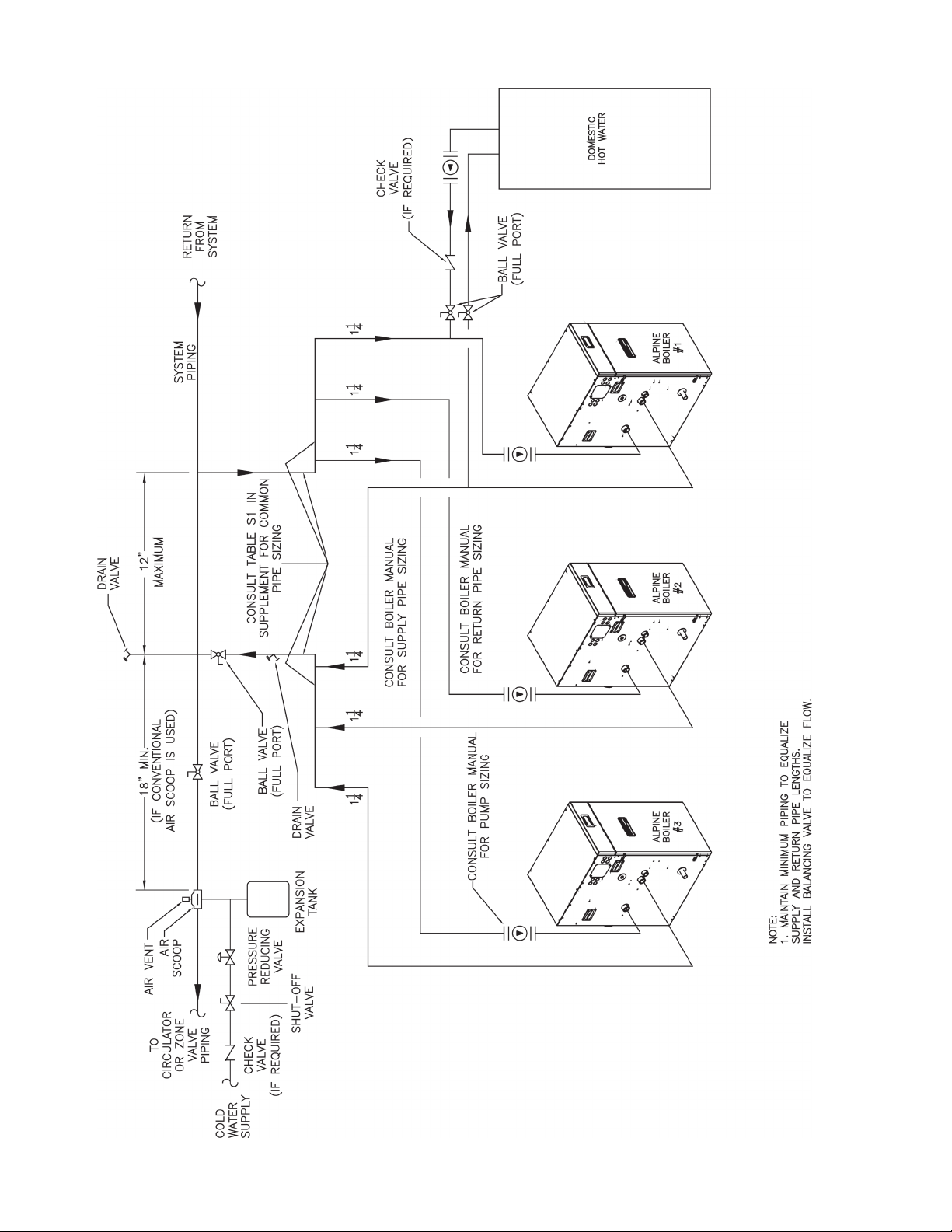
Figure S1: Modular Boiler Water Piping
2
Page 3

TABLE S1: MODULAR BOILER WATER MANIFOLD SIZING
Boiler
Model
ALP080 1¼” 1½” 2” 2½” 2½” 2½” 2½”
ALP105 1½” 2” 2” 2½” 2½” 2½” 3”
ALP150 2” 2” 2½” 2½” 2½” 3” 3½”
ALP210 2” 2½” 3” 3” 3½” 4” 4”
ALP285 2½” 2½” 3” 3½” 3½” 4” 5”
ALP399 2½” 3” 3 4” 4” 5” 5”
2 3 4 5 6 7 8
Recommended Minimum Common Water Manifold Size (NPT)
E. Gas Piping
1. Refer to National Fuel Gas Code, Local Codes and
Tables 12A and 13 of the Installation, Operating and
Service Instructions for gas pipe sizing.
2. Each boiler must be piped as shown in Figure 26 of
the Installation, Operating and Service Instructions.
WARNING
If gas pressure in the building is above ½ psig,
an additional gas pressure regulator is required.
Using one additional regulator for multiple
boilers may result in unsafe boiler operation.
The additional regulator must be able to properly
regulate gas pressure at the input of the smallest
boiler. If the regulator cannot do this, two or
more additional regulators are required. Consult
regulator manufacturer and/or local gas supplier
for instructions and equipment ratings.
Number of Units
F. Electrical
1. Each boiler must be provided with a fused
disconnect and service switch.
2. Install wiring in accordance with requirements of
authority having jurisdiction. In the absence of such
requirements, follow the National Electric Code,
NFPA 70 and/or CSA C22.1 Electric Code.
G. Modular Boiler Control Systems
Contact a controls manufacturer such as Honeywell or
Tekmar to properly apply a modular control system.
Common systems may use outdoor temperature, return
water temperature or both to stage the boilers.
3
 Loading...