

Burnham 8B Series, 805B, 806B, 810B, 807B Installation, Operating And Servicing Instructions
...
SEIRESB8
RELIOBDERIF-SAG
DNAGNITAREPO,NOITALLATSNI
ROFSNOITCURTSNIECIVRES
,reliobnonoitamrofnignikeesnehW.rotcartnocgnitaehruoyllac,reliobotsriaperroecivresroF
.lebaLgnitaRnonwohssarebmuNlaireSdnarebmuNledoMrelioBedivorp
rebmuNledoMrelioBrebmuNlaireSrelioBetaDnoitallatsnI
____-_____8________6
rotcartnoCgnitaeH rebmuNenohP
sserddA
8141602R13-7/03
1
Price - $5.00
IMPORTANT INFORMATION - PLEASE READ THIS PAGE CAREFULLY
NOTE: The equipment shall be installed in accordance with those installation regulations enforced in the area where the
installation is to be made. These regulations shall be carefully followed in all cases. Authorities having jurisdiction
shall be consulted before installations are made.
All wiring on boilers installed in the USA shall be made in accordance with the National Electrical Code and/or local
regulations.
All wiring on boilers installed in Canada shall be made in accordance with the Canadian Electrical Code and/or local
regulations.
This Series 8B Boiler has been approved by the Massachusetts Board of Plumbers and Gas Fitters:
Approval No. G1-0202-11A.
The Commonwealth of Massachusetts requires this product to be installed by a licensed Plumber or Gas Fitter.
The following terms are used throughout this manual to bring attention to the presence of hazards of various risk levels,
or to important information concerning product life.
REGNAD
noitautissuodrazahyltnenimminasetacidnI
,htaednitluserlliw,dediovatonfi,hcihw
ytreporplaitnatsbusroyrujnisuoires
.egamad
.egamad
GNINRAW
noitautissuodrazahyllaitnetopasetacidnI
,htaednitluserdluoc,dediovatonfi,hcihw
ytreporplaitnatsbusroyrujnisuoires
.egamad
NOITUAC
noitautissuodrazahyllaitnetopasetacidnI
nitluseryam,dediovatonfi,hcihw
ytreporproyrujnironimroetaredom
ECITON
nosnoitcurtsnilaicepssetacidnI
ecnanetniamro,noitarepo,noitallatsni
otdetalertontubtnatropmierahcihw
.sdrazahyrujnilanosrep
REGNAD
rosihtfoytinicivehtnisdiuqilrosropavelbammalfrehtoroenilosagesuroerotsTONOD
.ecnailpparehtoyna
lacirtceleynahcuotTONOD-ecnailppaynaetarepootyrtTONOD,sropavsagllemsuoyfI
yletomeramorfreilppussagehtllac,yletaidemmI.gnidliubehtnienohpynaesurohctiws
,elbaliavanusireilppusehtfirosnoitcurtsnis'reilppussagehtwolloF.enohpdetacol
.tnemtrapederifehttcatnoc
elbitsubmocrevoetercnoc,teprac,gniroolfelbitsubmocnoreliobsihtllatsniTONOD
rognipipcitsalpsahcuslairetamdetceffataehynarevoetercnocnoron,doowrogniroolf
.dleihsroolfelbitsubmocdellatsniylreporpatuohtiwgniriw
2
GNINRAW
ehtwolloF.ylefasetarepootecivresdnaecnanetniamralugerseriuqerreliobsihT
.launamsihtnideniatnocsnoitcurtsni
ytreporpesuacnacecnanetniamroecivres,noitaretla,tnemtsujda,noitallatsnireporpmI
erofeblaunameritneehtdnatsrednudnadaeR.efilfossolroyrujnilanosrep,egamad
ebtsumecivresdnanoitallatsnI.ecivresro,noitarepopu-trats,noitallatsnignitpmetta
.ycnegaecivresrorellatsnidelliksdna,decneirepxe,elbaegdelwonkaybylnodemrofrep
.detnevylreporpebtsumreliobsihT
snoisivorperaerehtosdellatsniebtsumdnanoitarepoefasrofriahserfsdeenreliobsihT
.rianoitalitnevdnanoitsubmocetauqedarof
ehtfotratsehterofebdenaelcdnadetcepsniebtsummetsysgnitnevehtforoiretniehT
rofnosaesgnitaehehttuohguorhtyllacidoirepdetcepsniebdluohsdnanosaesgnitaeh
suoixonwollaotyrassecensimetsystnevdetcurtsbonudnanaelcA.snoitcurtsboyna
drawotetubirtnoclliwdnaylefastnevotefilfossolroyrujniesuacdluoctahtsemuf
.ycneiciffes'reliobehtgniniatniam
gnippatehtotnidellatsnisievlavfeilererusserpasselnuetelpmoctonsinoitallatsnI
roflaunamsihtfonoitceSmirTdnagnipiPretaWehteeS-reliobfopotehtnodetacol
.sliated
dnanwodtuhsotreliobehtesuacyamhcihwsecivedytefashtiwdeilppussireliobsihT
gnitaeheht,ytilibissopasisepipnezorfoteudegamadfI.ecivrestuohtiwtrats-erton
dnasdraugefasetairporpparo;rehtaewdlocnidednettanutfelebtondluohsmetsys
sireliobehtfiegamadtneverpotmetsysgnitaehehtnodellatsniebdluohssmrala
.evitareponi
sgnittifepipynawercsnutonoD.erusserphgihrednuretawtohyrevsniatnocreliobsihT
ehtgnirussaylevitisoptuohtiwreliobsihtfostnenopmocynatcennocsidottpmettaron
nehwtnempiuqednagnihtolcevitcetorpraewsyawlA.erusserponsahdnaloocsiretaw
ehtnoylertonoD.seirujnidlacstneverpotreliobsihtgnicivresropugnitrats,gnillatsni
.reliobehtfoerusserpdnaerutarepmetehtenimretedotseguagerutarepmetdnaerusserp
oD.gnitareposireliobehtnehwtohyrevemocebhcihwstnenopmocsniatnocreliobsihT
.loocerayehtsselnustnenopmocynahcuotton
,animulaniatnocleufehtdnanoitsubmocfostcudorp,noitcurtsnocfoslairetamrelioB
rocixotrehtoro/dnasedyhedla,sedixonegortin,edixonomnobrac,slatemyvaeh,acilis
ehtotnwonkerahcihwdnayrujnisuoiresrohtaedesuacnachcihwsecnatsbuslufmrah
esusyawlA.mrahevitcudorperrehtodnastcefedhtrib,recnacesuacotainrofilaCfoetats
ehtybraengnikrowrognicivresnehwtnempiuqednasrotaripser,gnihtolcytefasreporp
.ecnailppa
.htaedroyrujnilanosrepesuacnacredroreporpehtnisnoitcurtsnillawollofoteruliaF
slaunamsrerutcafunamtnenopmocnideniatnocesohtllagnidulcni,snoitcurtsnilladaeR
rogniniatniam,gnitarepo,pugnitrats,gnillatsnierofebreliobehthtiwdedivorperahcihw
.gnicivres
elbammalfrehtodnaenilosag,slairetamelbitsubmocmorfeerfdnaraelcaerareliobpeeK
.sdiuqilrosropav
.retawottcejbusneebsahhcihwlortnochtiwreliobetarepotonoD
.semitllataecalpniebtsumsdraugdnaserusolcne,setalprevocllA
ECITON
.launamsihtfokcabehtnodetnirpsihcihwfoypoca,ytnarrawdetimilasahreliobsihT
yltcerroceraslortnocllatahteesotrotcartnocgnillatsniehtfoytilibisnopserehtsitI
.etelpmocsinoitallatsniehtnehwylreporpgnitarepoeradnadellatsni
evahlevelaesevobateef000,2nahtretaergsedutitlatanoitallatsniroftliubsreliobASU
replevelaesevobateef000,1reptnecrep4etartupnisagecuderotdecifiroyllaicepsneeb
naidanaC.FxidneppAdna2.1.8noitceS,1.322ZISNA/45APFN,edoCsaGleuFlanoitaNeht
.lebalgnitarehtnodetacidnisignizisecifiro'sreliob
3

Table of Contents
I. Pre-Installation ................................................ 6
II. Boiler Assembly ................................................ 8
III. Gas Control System Assembly ....................... 15
(Knockdown Boilers)
IV. Water Trim and Piping .................................... 27
V. Gas Piping ....................................................... 31
VI. Venting ............................................................33
VII. Electrical .......................................................... 36
VIII. System Start-up ............................................... 59
IX. Service ............................................................. 68
X. Repair Parts ..................................................... 75
4
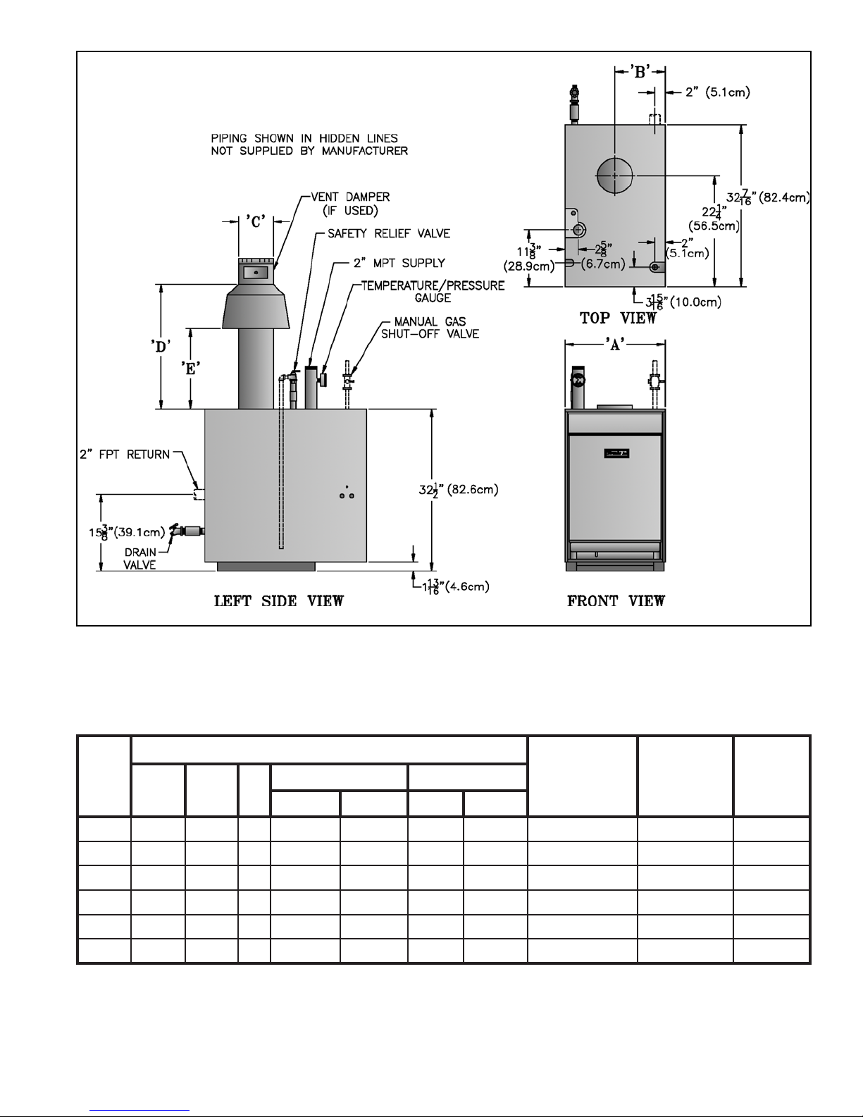
Table 1: Dimensional Data
Figure 1: Dimensional Data
relioB
ledoM
ABC
.oN
B50802017 61/31-4261/31-428/1-618/1-61.tf51x.aid"79.11096
B6084/3-328/7-118 61/31-724/3-528161.tf51x.aid"89.31077
B7082/1-724/3-319 61/31-824/3-528161.tf51x.aid"99.51578
B8084/1-138/5-519 61/31-0361/11-620261.tf51x.aid"99.71089
B908532/1-71012/1-3361/7-622251.tf51x.aid"019.910801
B0184/3-838/3-91012/1-3361/7-622251.tf51x.aid"019.120021
)1(
.)"4/1-73silenap
)2(
)3(
)4(
)sehcnI(snoisnemiD
DE
ASUadanaCASUadanaC
TPN1:ezisnoitcennocsaG
)ylnOretaW(isp05:erusserPgnikroWelbawollAmumixaM
.rellatsniybdeilppussenilneddihninwohssmetI
5
dednemmoceR
eziSyenmihC
)dnuoR(
retaW
tnetnoC
)snollaG(
.xorppA
gnippihS
thgieW
)BL(
pottekcajotroolf(thgiehreliobot"4/3-4sdda;gniroolfelbitsubmocnosnoitallatsnirofderiuqeresablaicepS
I. Pre-Installation
GNINRAW
erofebsnoitcurtsnilladaerylluferaC
llawollofoteruliaF.reliobgnillatsni
esuacnacredroreporpnisnoitcurtsni
.htaedroyrujnilanosrep
A. Inspect shipment carefully for any signs of damage.
All equipment is carefully manufactured, inspected and
packed. Our responsibility ceases upon delivery of
boiler to carrier in good condition. Any claim for
damage or shortage in shipment must be filed
immediately against carrier by consignee. No claims
for variances or shortages will be allowed by Boiler
Manufacturer, unless presented within sixty (60) days
after receipt of equipment.
B. Installation must conform to the requirements of the
authority having jurisdiction. In the absence of such
requirements, installation must conform to the
National Fuel Gas Code, NFPA 54/ANSI Z223.1 and/
or CAN/CGA B149 Installation Codes. Where
required by the authority having jurisdiction, the
installation must conform to the Standard for Controls
and Safety Devices for Automatically Fired Boilers,
ANSI/ASME No. CSD-1.
C. Provide clearance between combustible material
and boiler jacket (following clearances are minimums):
1. USA, 805B-807B: listed for Alcove installation
a. Front: 18"
b. Top: 36"
c. Draft hood, rear, sides and flue connector: 6"
2. USA, 808B-810B: for installation in room which is
large in comparison with size of boiler.
a. Front: 18"
b. Top: 51½"
c. Draft hood, rear, sides, and flue connector: 6"
3. Canada, 805B-810B:
a. Top and front: 18" (45.7cm)
b. Flue, rear and sides: 6" (15.2cm)
D. Provide clearance for servicing and proper operation
(following clearances are recommended and may be
reduced to minimum clearances shown above):
1. Single boiler, 805B-807B, Front/Top: 24" (61cm)
2. Single boiler, 808B-810B, Front/Top: 48" (122cm)
3. Multiple/modular boiler, USA/Canada, Sides:
1" (2.5cm)
E. Install boiler on level floor as close to chimney as
possible. For basement installation provide a solid base
such as concrete or masonry construction if floor is not
level or if water may be encountered on floor around
boiler.
F. Protect gas ignition system components from water
(dripping, spraying, rain, etc.) during boiler operation
and service (circulator replacement, control
replacement, etc.).
GNINRAW
noitallatsnirofdeifitrecngisedsiecnailppA
roF.ylnogniroolfelbitsubmocnonno
ylnogniroolfelbitsubmocnonoitallatsni
elbaTnidetsilesablaicepsnodellatsninehw
.gnitepracnodellatsniebtontsumrelioB.2
sihcihwetercnocnodellatsnisireliobnehW
gnitlemottcejbussitahtlairetamarevo
laicepseht,).cte,gnibuttnaidarXEP,CVP(
tonsidapetercnocA.desuebtsumesab
.gniroolfelbitsubmoctcetorpottneiciffus
Table 2: Special Base Required for Installation on
Combustible Flooring
.oNledoMrelioBrebmuNtraPesaBlaicepS
B50855061816
B60856061816
B70857061816
B80858061816
B90859061816
B01850161816
G. Provide combustion and ventilation air in
accordance with applicable provisions of local building
codes, or the National Fuel Gas Code, NFPA 54/ANSI
Z223.1, Section 5.3, Air for Combustion and
Ventilation; or CAN/CGA B149 Installation Codes,
Part 5, Venting Systems and Air Supply for
Appliances.
GNINRAW
rianoitalitnevdnanoitsubmocetauqedA
reporperussaotdedivorpebtsum
.noitsubmoc
The following guideline is based on the National Fuel
Gas Code, NFPA 54/ANSI Z223.1.
1. Determine volume of space (boiler room). Rooms
communicating directly with space (through
permanent openings not furnished with doors) are
considered part of space.
Volume [ft³] = Length [ft] x Width [ft] x Height [ft]
2. Determine Total Input of all appliances in space.
Round result to nearest 1,000 Btu per hour (Btuh).
3. Determine type of space. Divide Volume by Total
Input.
6

a. If result is greater than or equal to 50 ft³ per 1,000
Btuh, space is considered an unconfined space.
b. If result is less than 50 ft³ per 1,000 Btuh, space is
considered a confined space.
4. Determine building type. A building of unusually
tight construction has the following characteristics:
a. Walls and ceiling exposed to outside atmosphere
have a continuous water vapor retarder with a
rating of 1 perm or less with openings gasketed
and sealed, and
b. Weather-stripping has been added on openable
windows and doors, and
c. Caulking or sealants applied in joints around
window and door frames, between sole plates
and floors, between wall-ceiling joints, between
wall panels, at plumbing and electrical
penetrations, and at other openings.
5. For boiler located in an unconfined space in a
building of other than unusually tight construction,
adequate combustion and ventilation air is normally
provided by fresh air infiltration through cracks
around windows and doors.
6. For boiler located in an unconfined space in a
building of unusually tight construction or in a
confined space, provide outdoor air through
permanent opening(s) which communicate directly
or by duct with the outdoors or spaces (crawl or
attic) freely communicating with the outdoors.
Minimum dimension of air opening(s) is 3" (7.6cm).
a. Two permanent openings: Locate one opening
within 12 " (30.5cm) of top of space. Locate
remaining opening within 12" (30.5cm) of bottom
of space. Size each opening per following:
i. Minimum free area of 1 square inch per 3,000
Btu per hour input of all equipment in space.
ii. Free area shall not be less than the sum of
the areas of all vent connectors in the
confined space.
Alternate method for boiler located within confined
space. Use indoor air if two permanent openings
communicate directly with additional space(s) of
sufficient volume such that combined volume of all
spaces meet criteria for unconfined space. Size each
opening for minimum free area of 1 square inch per
1,000 Btu per hour input of all equipment in
spaces, but not less than 100 square inches.
7. Ventilation Duct Louvers and Grilles. Equip
outside openings with louvers to prevent entrance
of rain and snow, and screens to prevent entrance of
insects and rodents. Louvers and grilles must be
fixed in open position or interlocked with
equipment to open automatically before burner
operation. Screens must not be smaller than ¼ inch
mesh.
Consider the blocking effect of louvers, grilles and
screens when calculating the opening size to
provide the required free area. If free area of louver
or grille is not known, assume wood louvers have
20-25 percent free area and metal louvers and
grilles have 60-75 percent free area.
8. For Specially Engineered Installations. The above
requirements shall be permitted to be waived where
special engineering, consistent with good
engineering practice and approved by the authority
having jurisdiction, provides an adequate supply of
air for combustion, ventilation, and dilution of flue
gases.
i. Direct communication with outdoors.
Minimum free area of each opening must be
1 square inch per 4,000 Btu per hour input
of all equipment in space.
ii. Vertical ducts. Minimum free area of each
opening must be 1 square inch per 4,000
Btu per hour input of all equipment in
space. Duct cross-sectional area shall be
same as opening free area.
iii. Horizontal ducts. Minimum free area of
each opening must be 1 square inch per
2,000 Btu per hour input of all equipment
in space. Duct cross-sectional area shall be
same as opening free area.
b. One permanent opening shall be permitted where
the boiler has clearances of at least 1" (2.5cm)
from the sides and rear and 6" (15.2cm) from the
front. Locate the opening within 12 " (30.5cm) of
top of space. Size opening per following:
GNINRAW
rehtoroenilosagerehwreliobllatsnitonoD
fosecruosro,sdiuqilrosropavelbammalf
,srenaelc,sehcaelb.e.i(snobracordyh
cirbaf,srevomertniap,syarps,slacimehc
.derotsrodesuera).cte,srenetfos
ECITON
ehtotdragerhtiwreliobehtfognizis-siM
evissecxenitluserlliwdaolmetsysgnitaeh
tnenopmocdetareleccadnagnilcycreliob
tnarrawTONSEODmahnruB.eruliaf
reliobdezis-simybdesuacseruliaf
otreliobehtezisrevoTONOD.snoitacilppa
yltaergsreliobelpitlum/raludoM.metsyseht
.gnizisrevoreliobfodoohilekilehtecuder
7
II. Boiler Assembly
A. Remove Crate (Semi-Pak and Packaged Only)
1. Remove all fasteners at crate skid.
2. Lift outside container and remove with all other
inside protective spacers and bracing.
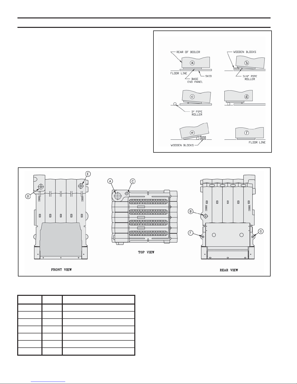
B. Remove boiler from skid. See Figure 2. Exercise care
to avoid dropping boiler.
1. Place boiler in approximate location. Refer to
Section I: Pre-Installation. Remove base hold down
bolts.
2. Using pry bar under rear corner of Base End Panel,
raise boiler and install 1½" wood blocks under rear
corners. Install ¾" pipe roller between Base and
skid.
3. Remove 1½" wood blocks. Place 3" pipe roller on
floor behind skid.
4. Roll boiler off skid. Move skid out of way.
Figure 2: Skid Removal
Table 3: Purpose of Tappings
gnippaTeziSesopruP
A"2ylppuS
B"2nruteR
C"¾evlaVfeileR
D"¾timiL
E"¾timiLyrailixuA
F"¾tuohsaW
G"¾niarD
Figure 3: Tapping Locations
8
5. Roll boiler until 3" roller is located as shown. Use
pry bar to install wood blocks under front corners of
base. Remove 3" roller.
6. Lift boiler with pry bar. Remove wood blocks.
Lower boiler.
C. For Packaged Boiler only, proceed to Paragraph E.
D. Test Section Assembly for leaks before connecting to
system and installing controls, trim and jacket. Refer
to Figure 3 and Table 3.
1. Plug Tappings C & E (¾ NPT) and Return Tapping
B (2 NPT).
2. Insert ¾" NPT x ¼" NPT bushing in Tapping D.
Install pressure gauge capable of indicating 50 psi.
3. Insert 2" NPT x ¾" NPT bushing in Supply
Tapping A. Install purge valve with a hose that
runs to a drain.
4. Connect fill valve and piping to Drain Tapping G.
GNINRAW
.reliobtsetkaelotriaesutonoD
5. Fill boiler completely with water by venting air
through purge valve. Close purge valve and apply
water pressure of at least 10 psi but less than 50 psi
gauge pressure.
6. Examine boiler for leaks or damage due to
shipment or handling.
7. Remove plugs from Return Tapping B, Tapping C,
and Tapping E (if second limit or operating control
is used). Also remove fill valve and piping, purge
valve and piping, and pressure gauge.
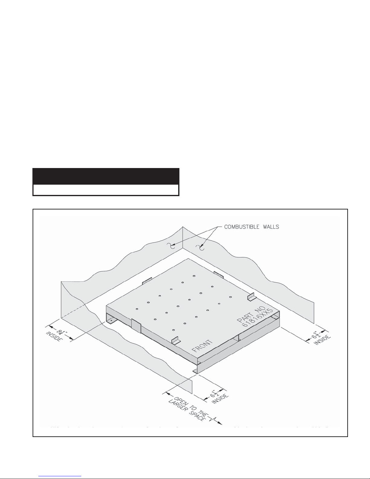
E. Install special base if installation is on combustible
flooring. See Figure 4. Floor shield adds 4¾" to boiler
height.
1. Place special base on combustible floor with surface
marked "FRONT" in upward position.
2. Locate special base with spacing to combustible
materials as shown in Figure 4.
3. Place boiler on special base. Boiler must rest inside
locating brackets. Boiler jacket panels will
overhang special base.
4. Do not enclose boiler (including special base) on all
four sides. Models 805B - 807B may be enclosed
Figure 4: Installation of Special Base for Combustible Flooring
9
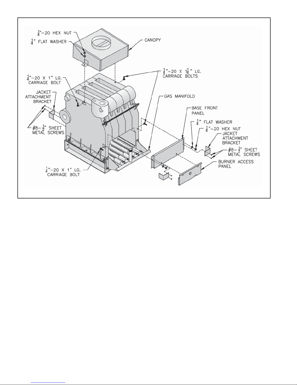
Figure 5: General Assembly (Knockdown Boilers)
on three sides (alcove) while maintaining
clearances shown in Figure 4.
F. Move boiler to permanent location by sliding or
walking. DO NOT DROP.
For Packaged Boiler proceed to Section IV: Trim and
Piping.
G. Install Canopy on section assembly. See Figure 5.
Canopy and hardware are located in Combination
Boiler Parts and Control Carton.
1. Position Canopy on top of Section Assembly.
Locate between end sections and sealing ledge on
front and back of each section.
2. Fasten each end with ¼" - 20 x 1" carriage bolts,
washers and nuts.
3. Seal between Canopy and Section Assembly with
furnace cement.
H. Inspect joints between sections. They were factory
sealed. If any openings resulted during shipment or
handling, reseal with furnace cement. Confirm tie rods
are only hand tight to allow for thermal expansion.
I. Install Base Front Panel. See Figure 5. Panel and
hardware located in Combination Boiler Parts and
Control Carton.
1. Attach Base Front Panel to Section Assembly using
¼" - 20 x 1¼" carriage bolts, washers and nuts.
2. Seal between top of Base Front Panel and Section
Assembly with furnace cement (shipped in
Combination Boiler Parts and Control Carton).
3. Seal between top of Base Rear Panel and Section
Assembly with furnace cement.
J. Install Pilot/Main Burner Assembly. See Figure 7.
Assembly is located in Combination Boiler Parts and
Control Carton. Verify assembly is properly located on
support bracket in Base Rear Panel, seated on Main
Burner Orifice, and secured with hitch pin clip.
K. Attach Flame Roll-out Switch to Burner Access
Panel. See Figure 6. Flame Roll-out Switch and
hardware are located in Combination Boiler Parts and
Control Carton. Flame Roll-out Switch is a single use
device - do not test with heat - switch cannot be reset.
10
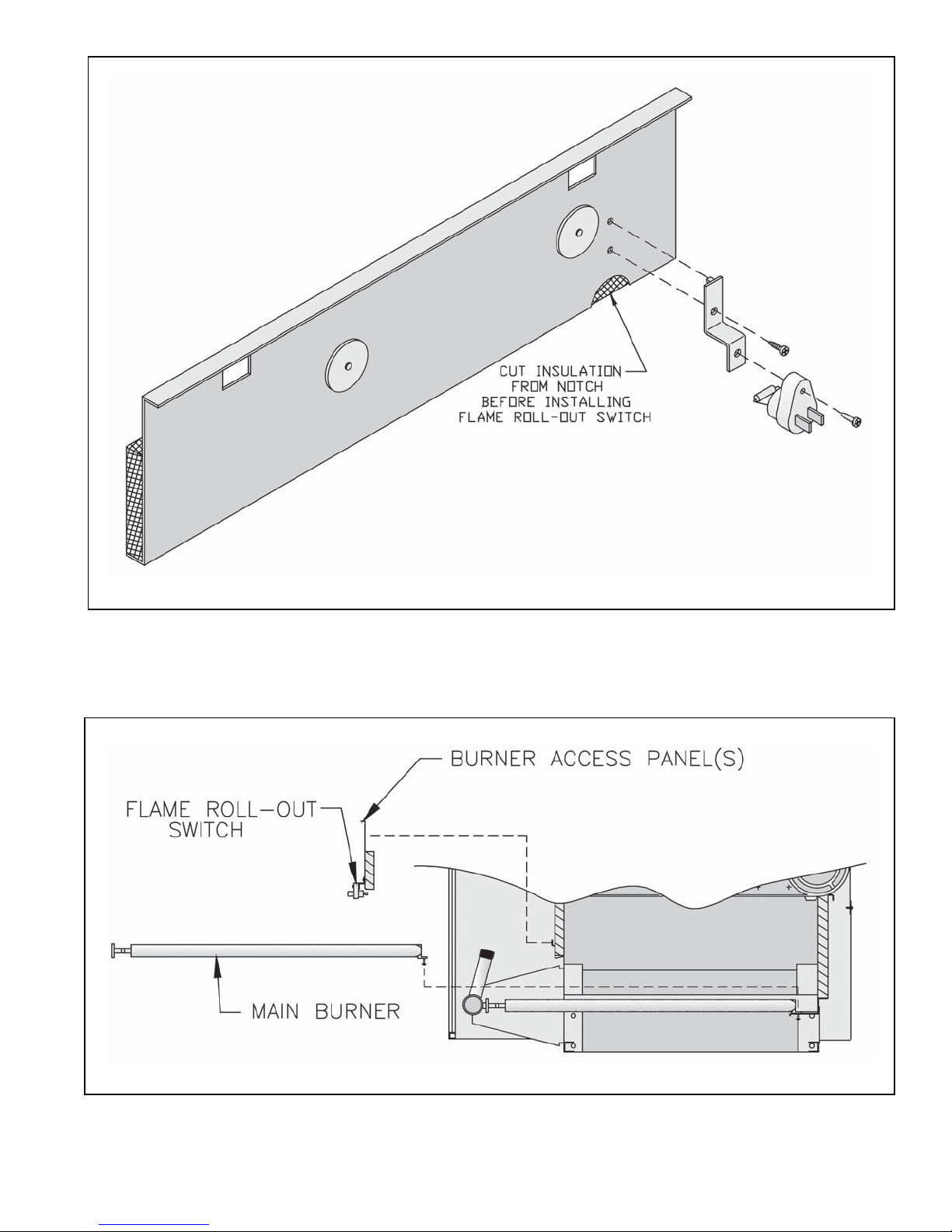
Figure 6: Flame Roll-out Switch Installation
Figure 7: Burner/Burner Access Panel Installation
11

1. Cut insulation from semicircular notch at right end of
the burner access panel. Models 808B - 810B have
two (2) burner access panels. Remove insulation
from notch of right side burner access panel only.
2. Attach Flame Roll-out Switch Mounting Bracket to
burner access panel with (1) #8 x ½" lg. sheet metal
screw.
3. Attach Flame Roll-out Switch to mounting bracket
with (1) #8 x ¾" lg. sheet metal screw.
L. Install Burner Access Panel(s). Locate Burner
Access Panel(s) in Combination Boiler Parts and
Control Carton. Engage Burner Access Panel holes
with projections on Base Front Panel. See Figure 6.
M. Install Immersion Well(s).
1. Remove Immersion Well(s) from Combination
Boiler Parts and Control Carton..
2. Insert Immersion Well in Tapping D. See Figure 3.
3. If second limit or operating control is used, insert
immersion well in Tapping E. If vertical gas
piping is to be installed inside of boiler jacket, it is
recommended that second limit be installed in
system piping.
7. Attach Lower Front Tie Bar to Left Side and Right
Side Panels.
8. Engage Upper Front Panel in slots on Left Side and
Right Side Panels. Place Top Panel in position.
Attach Top Panel to Left Side, Right Side and
Upper Rear Panels.
9. Tighten all jacket screws.
10. Affix Lighting/Operating Instructions Label and
Wiring Diagram Label to inside of Front
Removable Door. Labels are located in
Combination Boiler Parts and Control Carton.
O. Install Junction Box. See Figure 8. Attach junction
box to inside of Left Side Panel with ¼" - 20 x ¼" lg.
machine screw (located in Combination Boiler Parts
and Control Carton).
P. Install Limit Control. Locate limit in Combination
Boiler Parts and Control Carton. Insert limit probe into
left immersion well as far as possible. Tighten set
screw.
Q. Install Auxiliary Limit or operating control (if used).
Insert control probe into right immersion well as far as
possible. Tighten set screw.
N. Install Jacket. See Figure 8.
1. Locate four (4) Jacket Attachment Brackets in
Combination Boiler Parts and Control Carton.
Attach to Front Base Panel and Rear Base Panels
with #8 sheet metal screws. See Figure 5.
2. Hang Left Side Panel and Right Side Panel onto
Jacket Attachment Brackets.
3. Attach Lower Rear Panel to Left and Right Side
Panels. Do not tighten sheet metal screws.
4. Attach Upper Rear Panel to Lower Rear Panel. Do
not install three (3) upper screws.
5. Remove Rating Label and Combustible Clearance
Label from Combination Boiler Parts and Control
Carton. Attach to Vestibule Panel in locations
shown.
6. Attach Vestibule Panel to Left Side and Right Side
Panels.
R. Install Gas Control Assembly. Refer to Section III,
Gas Control System Assembly (Knockdown Boilers).
S. EP and OP System: See Figure 9.
1. Install pre-wired EP/OP Control Cabinet Assembly
to right front corner of jacket top panel.
2. Install Honeywell RM7890 Control (located in
RM7890 Control Carton).
3. EP Only: Remove RM7890's Dust Cover. With a
pair of side cutters, carefully snip both wire leads to
the brown resistor labelled "JR2" and discard it.
Replace Dust Cover.
4. Install Honeywell R7847 Flame Amplifier.
5. Install heat shield.
12
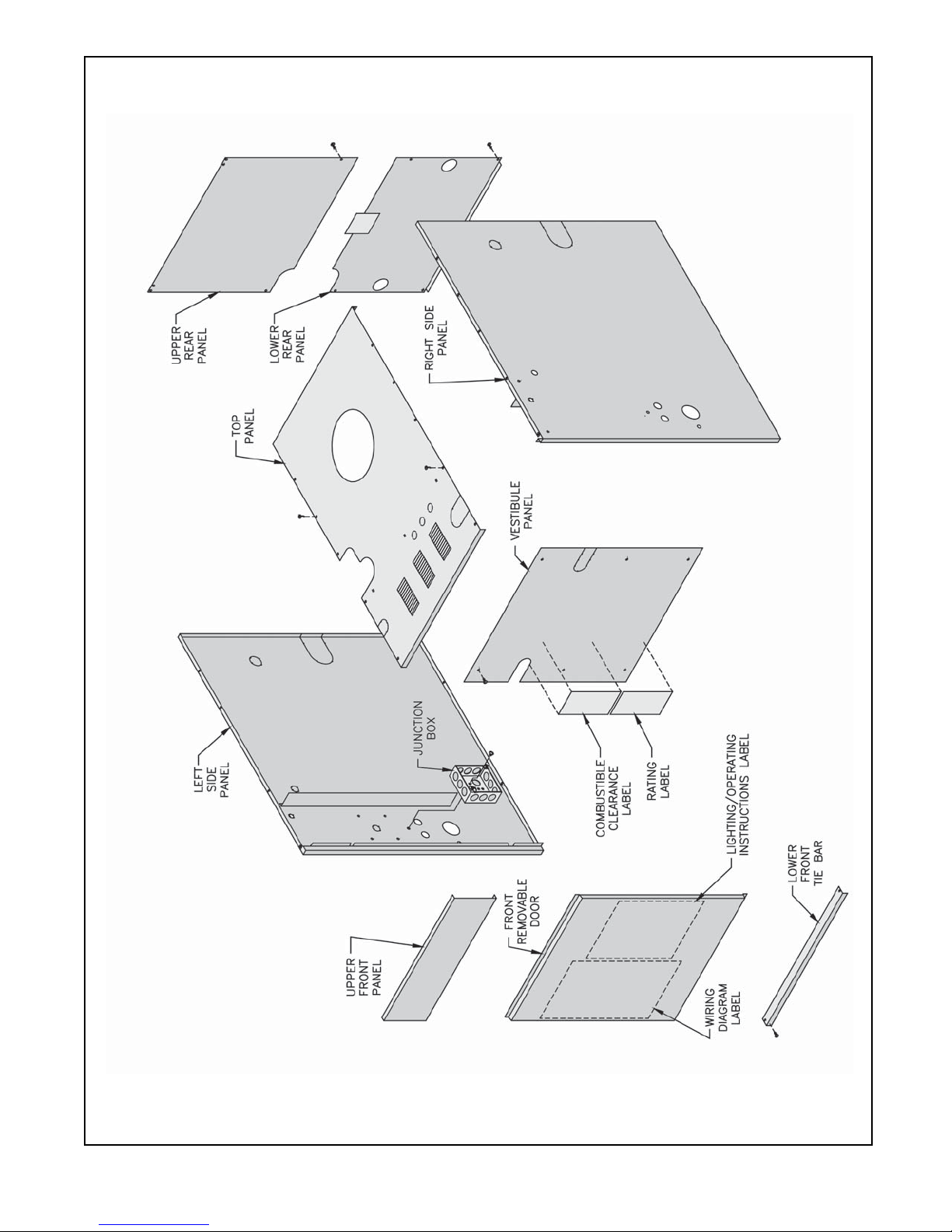
Figure 8: Jacket Assembly
13
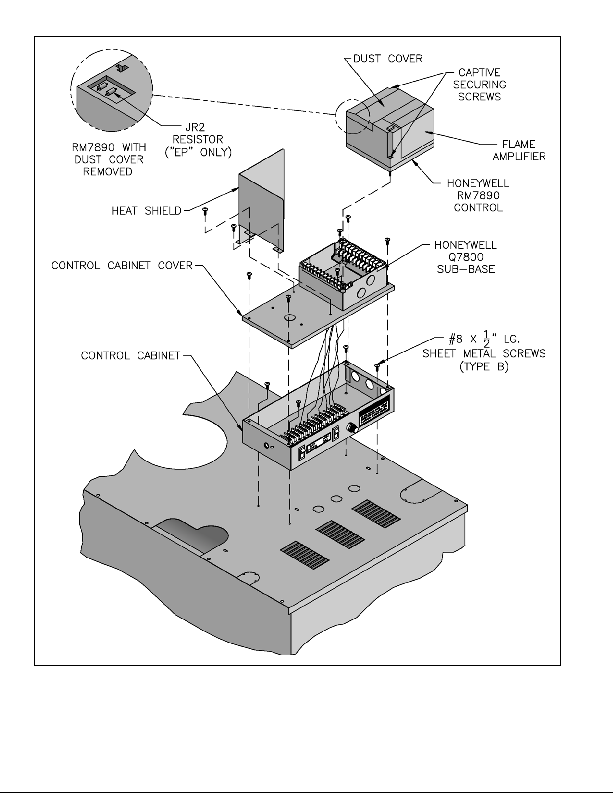
Figure 9: EP/OP Control Installation
14

III. Gas Control System Assembly (Knockdown Boilers)
A. 24V Standing Pilot Control System
Install Gas Control System. All components are
located in Combination Boiler Parts and Control Carton.
1. Install Gas Control Assembly on Manifold. See
Figure 10. Use thread (joint) compound (pipe dope)
resistant to action of liquefied petroleum gas.
2. Install pilot burner piping and controls. See Figure
10.
3. Connect Thermocouple Lead to Gas Valve.
4. Mount Transformer (continuous circulation) or
Control Center (intermittent circulation) to Junction
Box.
a. Canada only - loop 4" nylon cable tie between
junction box and transformer/control center.
b. Attach transformer/control center to junction
box.
B. EI (Intermittent Ignition)
Install Gas Control System. All components are
located in Combination Boiler Parts and Control Carton.
1. Install Gas Control Assembly on Manifold. See
Figure 11. Use thread (joint) compound (pipe dope)
resistant to action of liquefied petroleum gas.
2. Install pilot burner piping and controls.
a. Honeywell EI
i. USA - See Figure 12.
ii. Canada - See Figure 13.
b. Johnson EI
i. USA - See Figure 14.
ii. Canada - See Figure 15.
3. Install Ignition Module.
a. Attach Ignition Control Mounting Bracket to
Jacket Vestibule Panel using two (2) #8 x ½"
sheet metal screws.
b. Attach Johnson Ignition Module to Mounting
Bracket using two (2) #6 x ¾" sheet metal screws
or attach Honeywell Ignition Module to
Mounting Bracket using two (2) #8 x ½" sheet
metal screws.
c. Connect pilot ground wire and ignitor/sensor
lead(s) to ignition module. Refer to "Section VII:
Electrical" for connection details.
4. Mount Transformer (continuous circulation) or
Control Center (intermittent circulation) to Junction
Box. See Figure 8.
a. Canada only - loop 4" nylon cable tie between
junction box and transformer/control center.
b. Attach transformer/control center to junction
box.
C. OP Control System
Install Gas Control System. All components are
located in Combination Boiler Parts and Control Carton.
1. Install Gas Control Assembly on Manifold. See
Figure 16. Use thread (joint) compound (pipe dope)
resistant to action of liquefied petroleum gas.
2. Install pilot burner piping and controls. See Figure
16.
3. Connect Thermocouple Lead to Gas Valve.
4. Mount Transformer (continuous circulation) or
Control Center (intermittent circulation) to Junction
Box.
a. Canada only - loop 4" nylon cable tie between
junction box and transformer/control center.
b. Attach transformer/control center to junction
box.
D. OP-CSD-1 Control System
Install Gas Control System. All components are
located in Combination Boiler Parts and Control Carton.
1. Install Gas Control Assembly on Manifold. See
Figure 17. Use thread (joint) compound (pipe dope)
resistant to action of liquefied petroleum gas.
2. Mount pilot switch.
3. Install pilot burner piping and controls. See Figure
17.
4. Connect Thermocouple lead to pilot switch.
5. Mount Transformer (continuous circulation) or
Control Center (intermittent circulation) to Junction
Box.
6. Attach transformer/control center to junction box.
E. EP Control System
Install Gas Control System. All components are
located in Combination Boiler Parts and Control Carton.
1. Install Gas Control Assembly on Manifold. See
Figure 18.
2. Install pilot burner piping and controls. See Figure
18.
3. Install Ignition Transformer.
a. Attach Ignition Transformer to Jacket Vestibule
Panel using four (4) #8 x ½" lg. sheet metal
screws.
b. Connect Ignition Lead from Pilot to Ignition
Transformer.
4. Mount Transformer (continuous circulation) or
Control Center (intermittent circulation) to Junction
Box.
a. Canada only - loop 4" nylon cable tie between
junction box and transformer/control center.
15

b. Attach transformer/control center to junction
box.
Panel using four (4) #8 x ½" lg. sheet metal
screws.
F. EP-CSD-1 Control System
Install Gas Control System. All components are
located in Combination Boiler Parts and Control Carton.
1. Install Gas Control Assembly on Manifold. See
Figure 19.
2. Install pilot burner piping and controls. See Figure
19.
3. Install Ignition Transformer.
a. Attach Ignition Transformer to Jacket Vestibule
b. Connect Ignition Lead from Pilot to Ignition
Transformer.
4. Mount Transformer (continuous circulation) or
Control Center (intermittent circulation) to Junction
Box.
a. Canada only - loop 4" nylon cable tie between
junction box and transformer/control center.
b. Attach transformer/control center to junction
box.
16
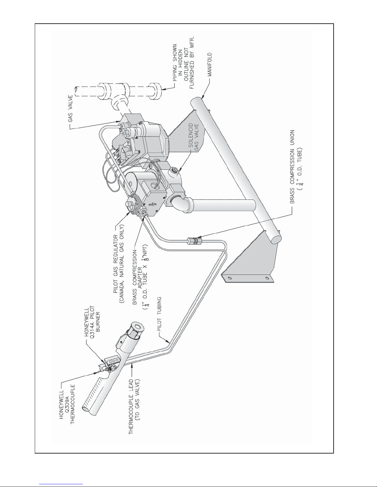
Figure 10: Schematic Gas Piping, 24V Standing Pilot, 806B & 807B
17
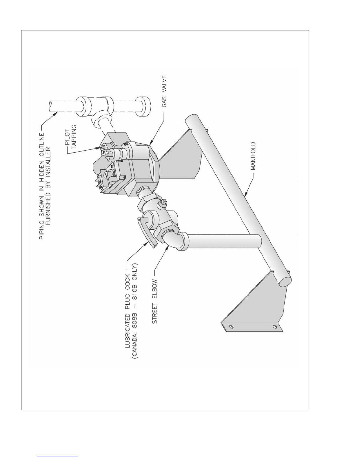
Figure 11: Main Gas Piping, Intermittent Ignition (EI)
18
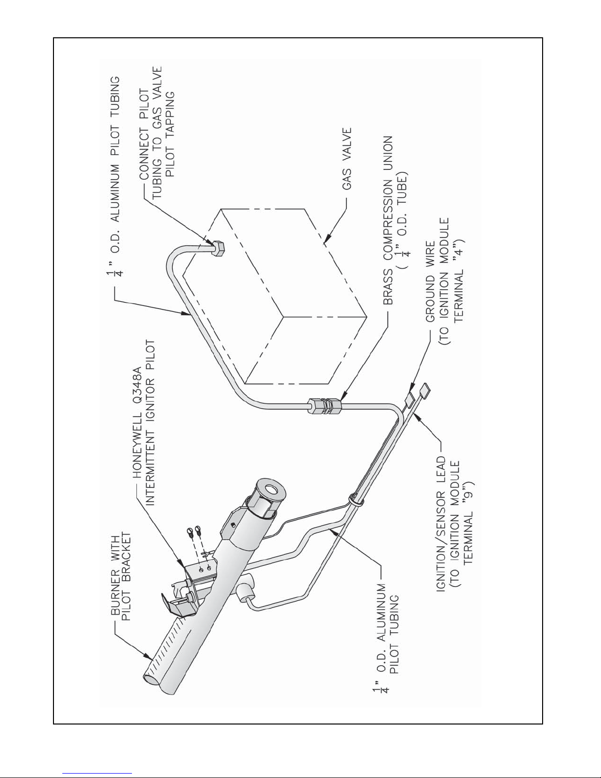
Figure 12: Schematic Pilot Piping (Honeywell EI), USA
19
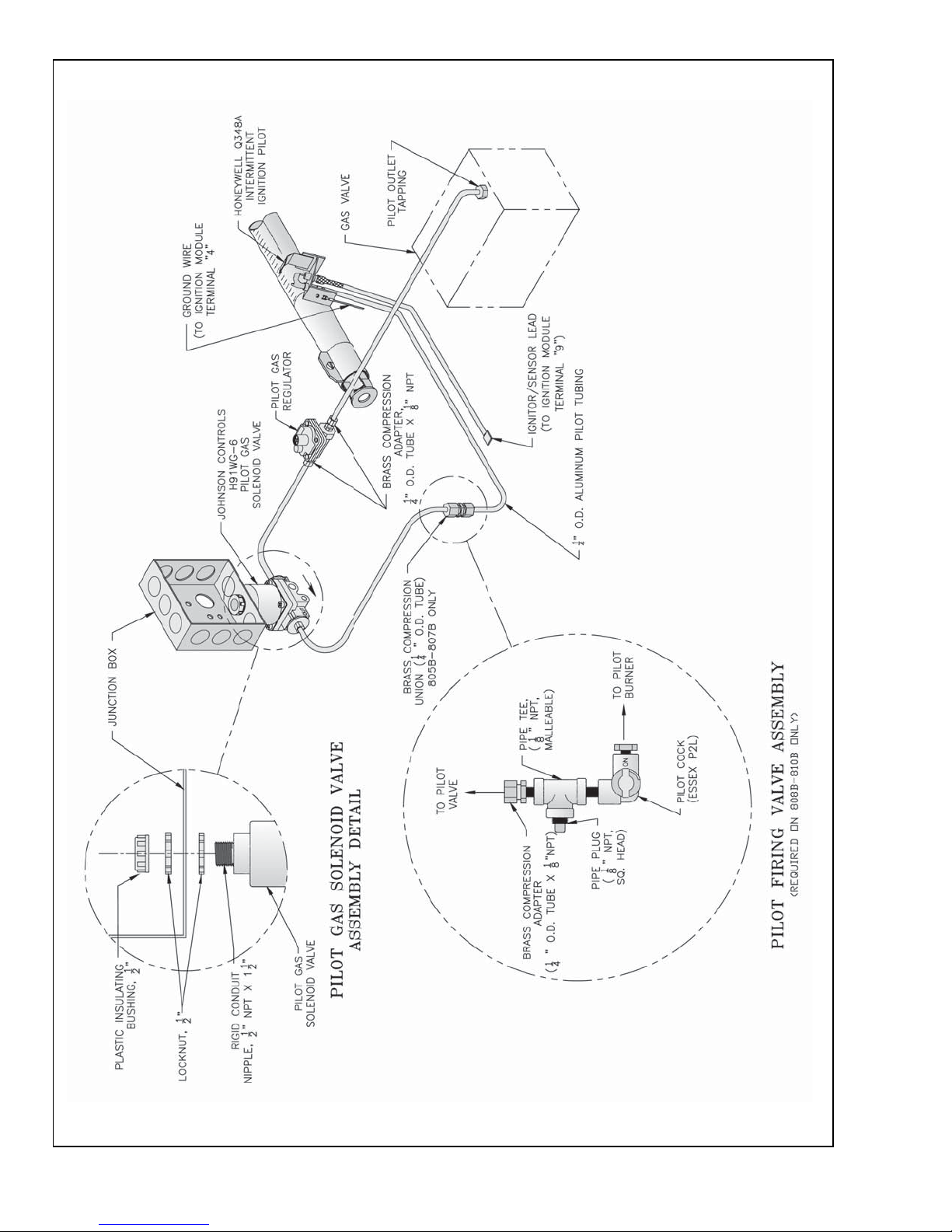
Figure 13: Schematic Pilot Piping (Honeywell EI)
Canada: Natural Gas, 805B - 810B; LP Gas, 806B - 807B
20
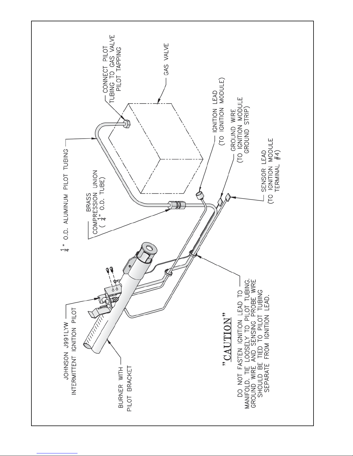
Figure 14: Schematic Pilot Piping (Johnson EI), USA
21
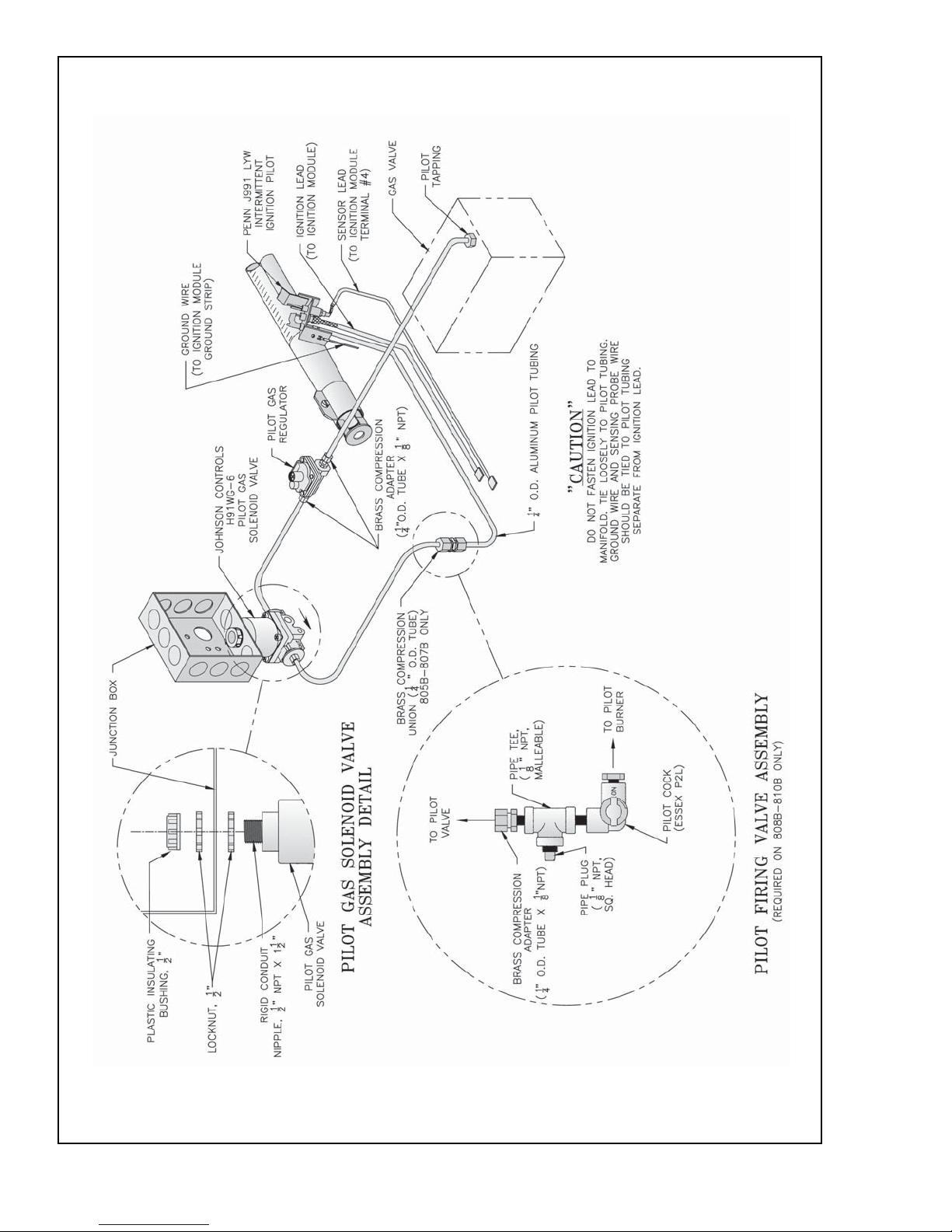
Figure 15: Schematic Pilot Piping (Johnson EI)
Canada: Natural Gas, 805B - 810B; LP Gas, 806B - 807B
22
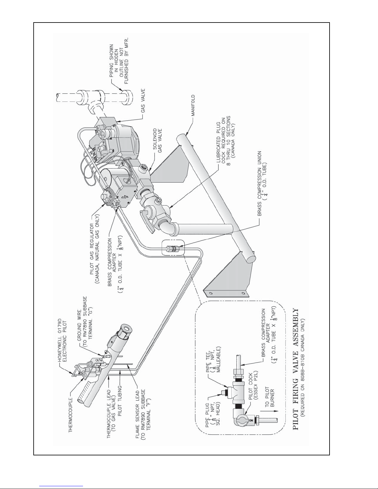
Figure 16: Schematic Gas Piping, OP Control System, 806B - 810B
23
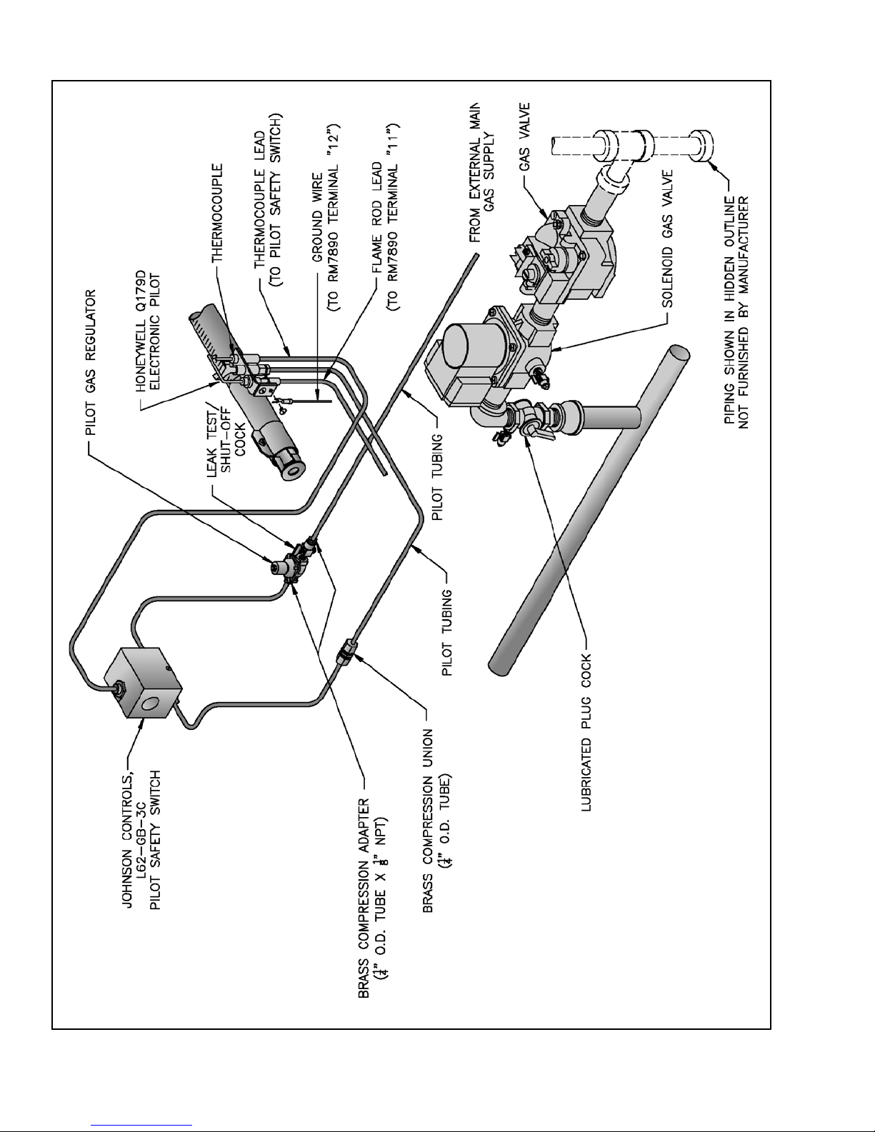
Figure 17: Schematic Gas Piping, OP-CSD-1 Control System, 808B - 810B
24
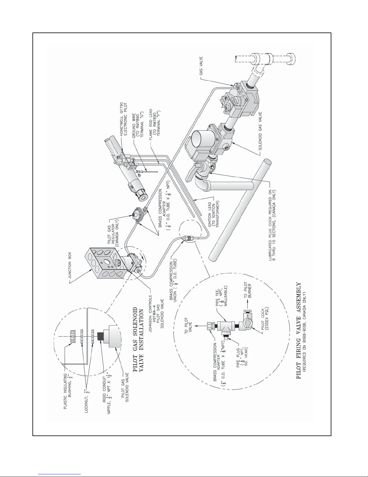
Figure 18: Schematic Gas Piping, EP Control System (Natural Gas Only), 806B - 810B
25
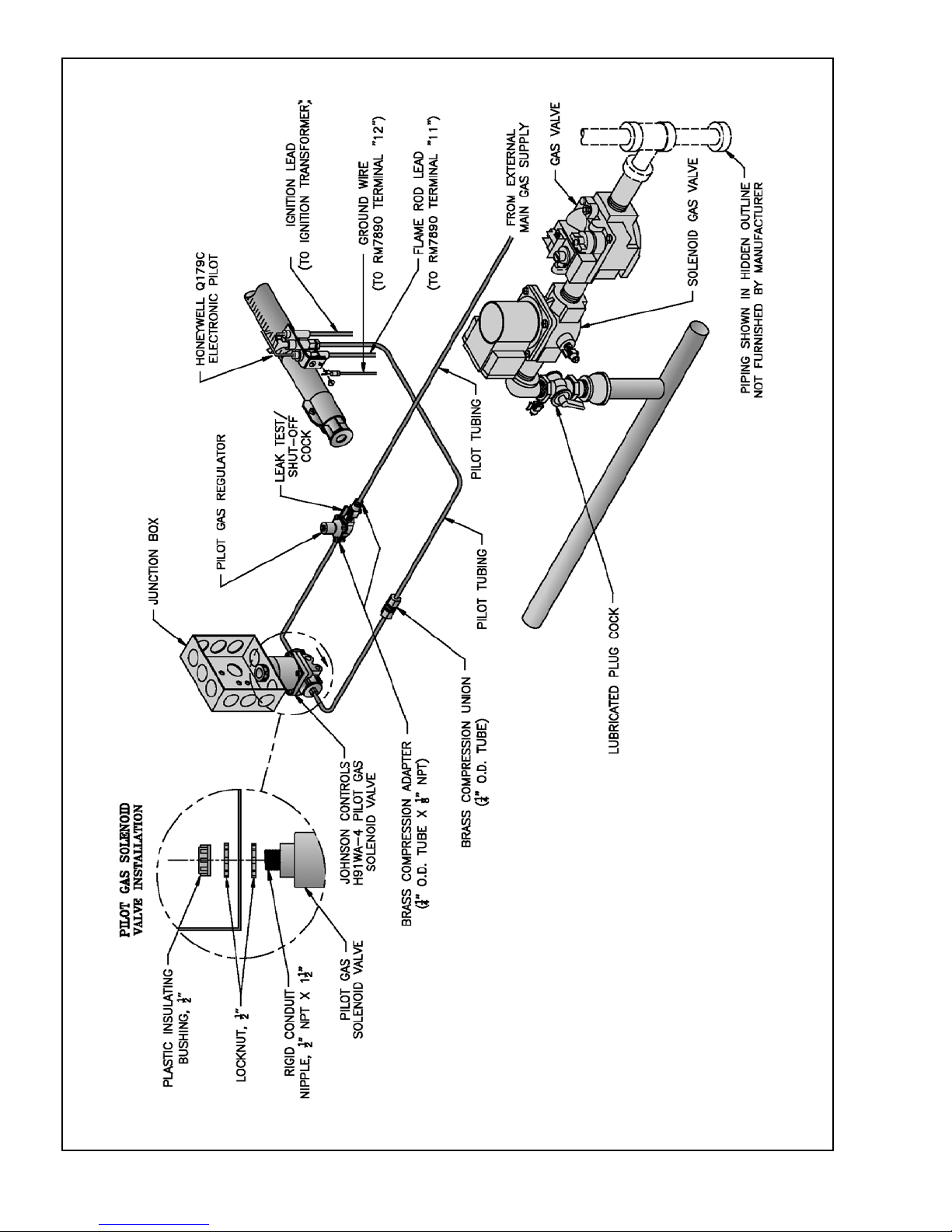
Figure 19: Schematic Gas Piping, EP-CSD-1 Control System, 808B - 810B
26
IV. Water Trim and Piping
.erutcurts
.retawfonoitidda
GNINRAW
roreliobotegamaddnanoitareporeporpminitluseryamreliobepipylreporpoteruliaF
reliobleetsdnanorifonoisorrocesuaclliwretawreliobfonoitanimatnocnegyxO
smelborprevoctonseodytnarraWs'mahnruB.eruliafreliobotdaelnacdna,stnenopmoc
tneuqerfybdesuacpu-dliub)emil(elacsroretawreliobfonoitanimatnocnegyxoybdesuac
A. Design and install boiler and system piping to prevent
oxygen contamination of boiler water and frequent water
additions.
1. There are many possible causes of oxygen
contamination such as:
a. Addition of excessive make-up water as a result
of system leaks.
b. Absorption through open tanks and fittings.
c. Oxygen permeable materials in the distribution
system.
2. In order to insure long product life, oxygen sources
must be eliminated. This can be accomplished by
taking the following measures:
a. Repairing system leaks to eliminate the need for
addition of make-up water.
b. Eliminating open tanks from the system.
c. Eliminating and/or repairing fittings which allow
oxygen absorption.
d. Use of non-permeable materials in the
distribution system.
e. Isolating the boiler from the system water by
installing a heat exchanger.
f. Use properly designed and operating air
elimination devices in water piping.
B. Design system to obtain a 20°F temperature rise through
the boiler (see Table 4). If a temperature rise greater
than 40°F is desired, consult Burnham.
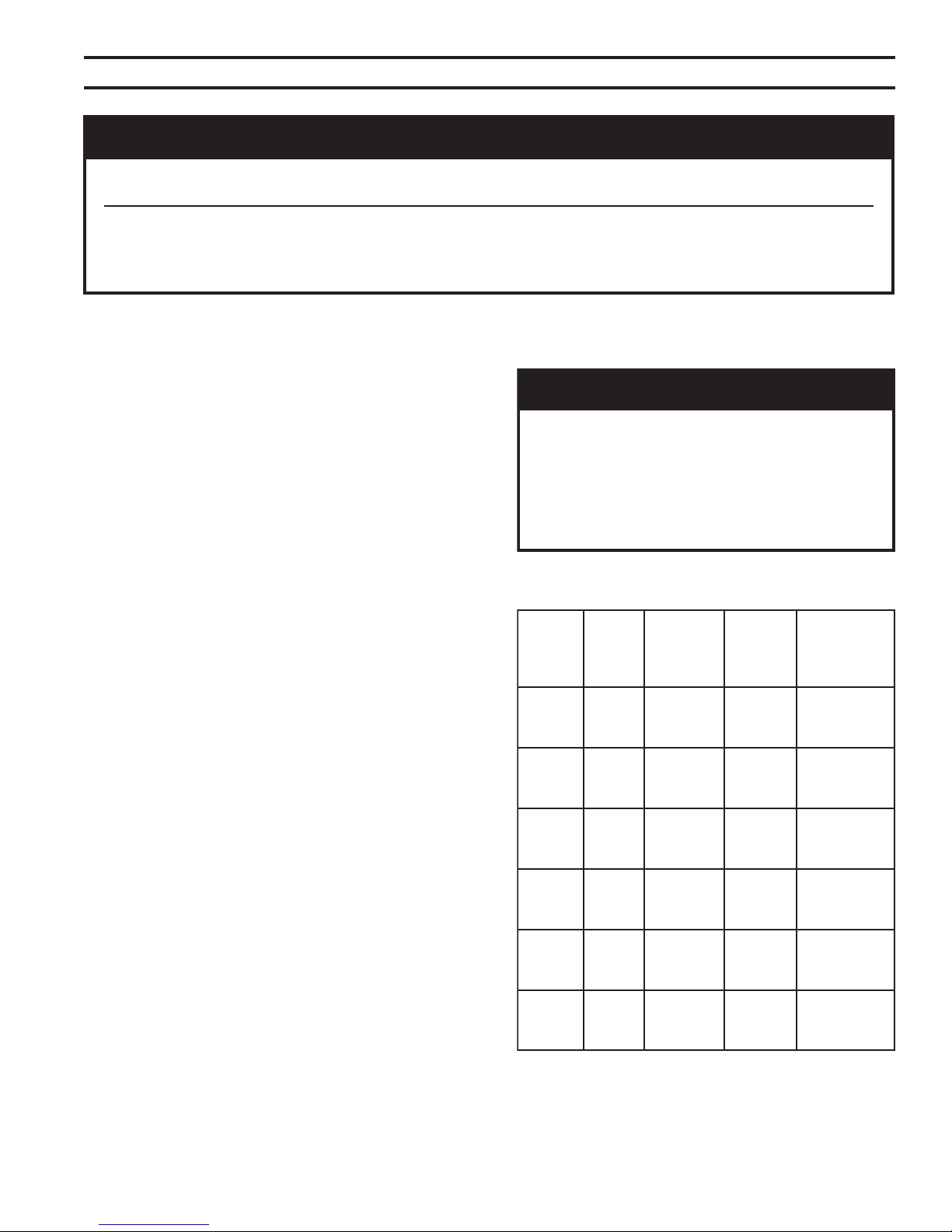
C. Install Safety Relief Valve. See Figure 20. Components
are located in Water Trim Carton. Safety Relief Valve
must be installed with spindle in vertical position.
1. Install ¾" NPT x 3½" lg. nipple in tapping "C". See
Figure 3.
2. Install safety relief valve on ¾" NPT nipple.
GNINRAW
.tnemegnarragnipip
Table 4: Flow Rate, Temperature Rise, and
Pressure Drop
RELIOB
EZIS
B508
B608
B708
B808
B908
B018
WOLF
ETAR
)MPG(
12
41
01
62
71
31
13
12
51
73
42
81
24
82
12
74
13
32
.PMET
ESIR
URHT
RELIOB
F°02
F°03
F°04
F°02
F°03
F°04
F°02
F°03
F°04
F°02
F°03
F°04
F°02
F°03
F°04
F°02
F°03
F°04
.NIM
RELIOB
GNIPIP
)TPN(
"½1
"¼1
"¼1
"½1
"½1
"¼1
"2
"½1
"¼1
"2
"½1
"½1
"2
"2
"½1
"2
"2
"½1
tsumgnipipegrahcsidevlavfeilererusserP
erevesfolaitnetopehttahthcusdepipeb
ynaniepipTONOD.detanimilesisnrub
TONOD.ruccodluocgnizeerferehwaera
.spacrosgulp,sevlavffotuhsynallatsni
egrahcsidreporprofsedoClacoLtlusnoC
RELIOB
ERUSSERP
PORD
'3
'2
'1
'3
'2
'1
'3
'2
'1
'3
'2
'1
'3
'2
'1
'3
'2
'1
27
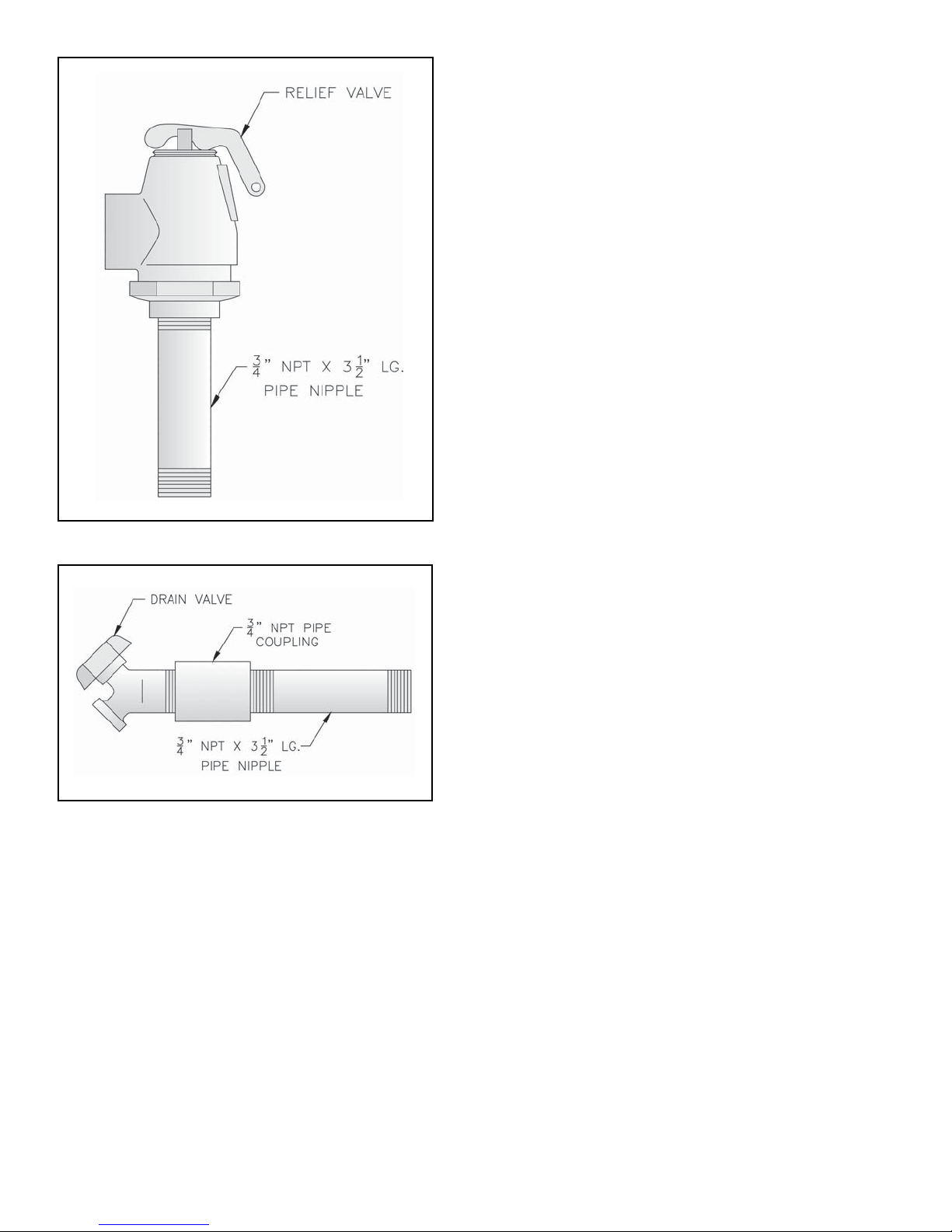
Figure 20: Safety Relief Valve Installation
Figure 21: Drain Piping Installation
b. Insert Temperature-Pressure Gauge. Tighten by
applying pressure to square shank on back of
gauge. DO NOT APPLY PRESSURE ON GAUGE
CASE since this may ruin gauge calibration.
2. Alternate Temperature-Pressure Gauge Piping. See
Figure 23.
a. Install 2 NPT x 10" Nipple into Supply Tapping
"A". See Figure 3.
b. Install 2 NPT x ¾ NPT x 2 NPT Tee (provided) or
2 NPT x 2 NPT x ¾ NPT Tee (installer furnished).
¾" NPT leg should face forward.
c. Install ¾ NPT x ¼ NPT Bushing.
d. Insert Temperature-Pressure Gauge. Tighten by
applying pressure to square shank on back of
gauge. DO NOT APPLY PRESSURE ON GAUGE
CASE since this may ruin gauge calibration.
F. Connect system supply and return piping to boiler. See
Figure 25. Also consult I=B=R Installation and Piping
Guides. Maintain minimum ½ inch clearance from hot
water piping to combustible materials.
1. If boiler is used in connection with refrigeration
systems, boiler must be installed with chilled medium
piped in parallel with heating boiler using
appropriate valves to prevent chilled medium from
entering boiler. See Figure 24. Also consult I=B=R
Installation and Piping Guides.
2. If boiler is connected to heating coils located in air
handling units where they may be exposed to
refrigerated air, boiler piping must be equipped with
flow control valves to prevent gravity circulation of
boiler water during cooling system operation.
3. Use boiler bypass if boiler is operated in system
which has a large volume or excessive radiation
where low boiler water temperatures may be
encountered (i.e. converted gravity circulation
system, etc.). See Figure 25.
4. A hot water boiler installed above radiation level
must be provided with a low water cutoff device as
part of installation.
D. Install Drain Valve in rear of Left End Section, Tapping
"G". See Figure 21. Components are located in Water
Trim Carton.
E. Install Temperature-Pressure Gauge. Components are
located in Water Trim Carton.
1. Standard Temperature - Pressure Gauge Piping. See
Figure 22.
a. Install 2" NPT x 10" lg. nipple with gauge tapping
into Supply Tapping "A". See Figure 3. Gauge
tapping should face forward.
5. A start-up strainer is recommended for practically all
modular installations (new and replacement alike) to
prevent system debris and sediment from ending up
in the boilers where it will inhibit heat transfer and
may eventually cause a cast iron section to crack
from overheating.
G. Alliance Water Heater (if used). Refer to Alliance
Installation, Operating and Service Instructions for
additional information. Install in same manner as space
heating zone.
28
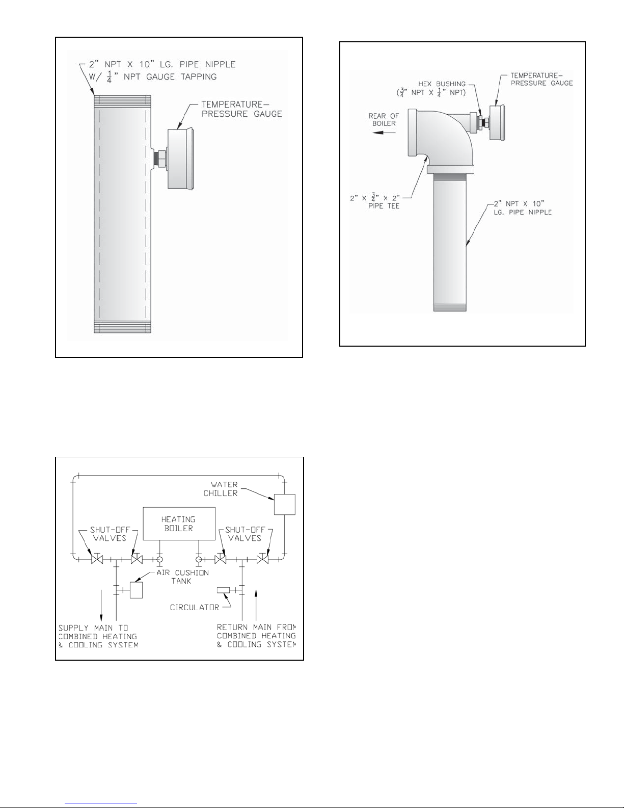
Figure 22: Temperature-Pressure Gauge
Installation
Figure 23: Alternate Temperature-Pressure
Gauge Installation
Figure 24: Recommended Piping for Combination
Heating & Cooling (Refrigeration) System
29
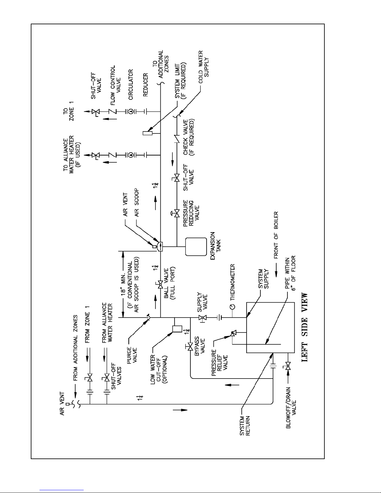
Figure 25: Recommended Boiler Piping for Circulator Zoned Heating Systems
30
 Loading...