

Page 1
Type 8026 - 8036 - 8076
Flowmeters with paddle wheel
Quickstart
English
Page 2
We reserve the right to make technical changes without notice.
Technische Änderungen vorbehalten.
Sous réserve de modifications techniques.
© 2009-2012 Bürkert SAS
Quickstart 1207/1_EU-ML_00561813_original_FR
1. ABOUT THE QUICKSTART.........................................................................3
2. INTENDED USE ................................................................................................4
3. BASIC SAFETY INFORMATION ...............................................................4
4. GENERAL INFORMATION ...........................................................................6
5. DESCRIPTION OF THE NAME PLATE ..................................................6
6. TECHNICAL DATA ...........................................................................................7
7. INSTALLATION AND WIRING .................................................................17
8. ADJUSTMENT AND COMMISSIONING ............................................27
9. MAINTENANCE AND TROUBLESHOOTING ..................................40
10. PACKAGING, TRANSPORT ...................................................................40
12. DISPOSAL OF THE PRODUCT ........................................................... 41
Page 3
Type 8026- 8036- 8076
Warns against material damage.
Failure to observe this warning may result in damage to the device
About the Quickstart
1. ABOUT THE QUICKSTART
This Quickstart describes the entire life cycle of the device. Please
keep this Quickstart in a safe place, accessible to all users and any
new owners.
Important safety information.
Respect the safety instructions. Study in particular the chapters
entitled Intended Use and Basic Safety Instructions.
• The quickstart must be read and understood.
The quickstart explains how to install, adjust, and start-up the device.
A detailed description of the device can be found in the related ope-
rating instructions available on the CD delivered with the device.
1.1. Symbols used
danger
Warns against an imminent danger.
• Failure to observe this warning can result in death or in serious
injury.
Warning
Warns against a potentially dangerous situation.
• Failure to observe this warning can result in serious injury or even
death.
attention
Warns against a possible risk.
• Failure to observe this warning can result in substantial or minor
injuries.
note
•
or system.
Indicates additional information, advice or important
recommendations.
Refers to information contained in this manual or in other
documents.
→ Indicates a procedure to be carried out.
1.2. Definition of the word "device"
→ The word "device" used within this manual refers to the flow-
meter type 8026, 8036 or 8076.
English
3
Page 4
Type 8026- 8036- 8076
Intended use
2. INTENDED USE
Use of the device that does not comply with the instructions
could present risks to people, nearby installations and the
environment.
• 8026, 8036 and 8076 devices are intended to measure the
flow rate of liquids:
- 8026 and 8036 flowmeters are used to measure the flow of
neutral or slightly aggressive liquids,
- 8076 flowmeters are used to measure the flow rate of
viscous liquids such as honey or oil, which are free of solid
particles.
• This device must be protected against electromagnetic interference, ultraviolet rays and, when installed outdoors, the effects
of climatic conditions.
• This device must be used in compliance with the characteristics
and commissioning and use conditions specified in the contractual documents and in the user manual.
• Requirements for the safe and proper operation of the device
are proper transport, storage and installation, as well as careful
operation and maintenance.
• Only use the device as intended.
→ Observe any existing restraints when the device is exported.
3. BASIC SAFETY INFORMATION
This safety information does not take into account:
• any contingencies or occurences that may arise during installation,
use and maintenance of the devices.
• the local safety regulations for which the operating company
is responsible including the staff in charge of installation and
maintenance.
Danger due to high pressure in the installation.
• Stop the circulation of fluid, cut off the pressure and drain the
pipe before loosening the process connections.
Danger due to electrical voltage.
• Shut down and isolate the electrical power source before carrying out work on the system.
• Observe all applicable accident protection and safety regulations
for electrical equipment.
Danger due to high temperatures of the fluid.
• Use safety gloves to handle the device.
• Stop the circulation of fluid and drain the pipe before loosening
the process connections.
Danger due to the nature of the fluid.
• Respect the prevailing regulations on accident prevention and
safety relating to the use of aggressive fluids.
4
English
Page 5
Type 8026- 8036- 8076
Basic safety information
Various dangerous situations
To avoid injury take care:
• to prevent any unintentional power supply switch-on.
• to ensure that installation and maintenance work are
carried out by qualified, authorised personnel in possession of
the appropriate tools.
• to guarantee a defined or controlled restarting of the process,
after a power supply interruption.
• to use the device only if in perfect working order and in compliance with the instructions provided in the instruction manual.
• to observe the general technical rules when installing and using
the device.
• not to use the device in explosive atmospheres.
• not to use the device for the measurement of gas flow rates.
• not to use the device in an environment incompatible with the
materials it is made of.
• not to use fluid that is incompatible with the materials the device
is made of.
• not to subject the device to mechanical loads (e.g. by placing
objects on top of it or by using it as a step).
• Do not make any external modifications to the device. Do not
paint or varnish any part of the device.
note
The device may be damaged by the fluid in contact with.
• Systematically check the chemical compatibility of the component materials of the device and the fluids likely to come into
contact with it (for example: alcohols, strong or concentrated
acids, aldehydes, alkaline compounds, esters, aliphatic compounds, ketones, halogenated aromatics or hydrocarbons,
oxidants and chlorinated agents).
note
Elements / Components sensitive to electrostatic discharges
• This device contains electronic components sensitive to electrostatic discharges. They may be damaged if they are touched by
an electrostatically charged person or object. In the worst case
scenario, these components are instantly destroyed or go out of
order as soon as they are activated.
• To minimise or even avoid all damage due to an electrostatic
discharge, take all the precautions described in the EN 613405-1 and 5-2 norms.
• Also ensure that you do not touch any of the live electrical
components.
English
5
Page 6
Type 8026- 8036- 8076
General information
4. GENERAL INFORMATION
4.1. Manufacturer's address and
international contacts
To contact the manufacturer of the device, use following address:
Bürkert SAS
Rue du Giessen
BP 21
F-67220 TRIEMBACH-AU-VAL
You may also contact your local Bürkert sales office.
The addresses of our international sales offices are available on the
internet at: www.burkert.com
4.2. Warranty conditions
The condition governing the legal warranty is the conforming use
of the in observance of the operating conditions specified in this
manual.
4.3. Information on the Internet
You can find the user manuals and technical data sheets regarding
the types 8026, 8036 or 8076 at: www.burkert.com
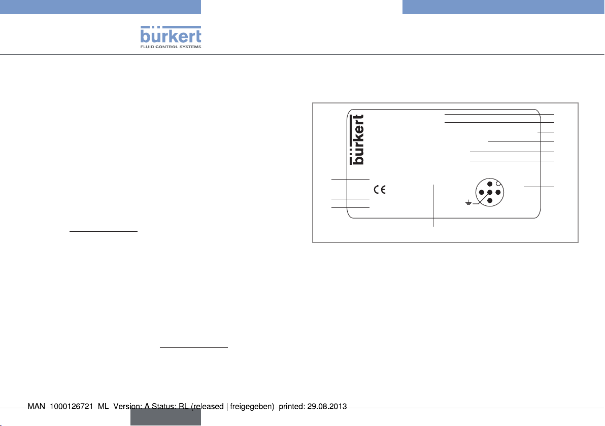
5. DESCRIPTION OF THE NAME PLATE
8026 Flow-Meter
Supply: 14-36VDC
Output: 1x4-20mA 2xTransistors 500 mA Max
Cell: HALL INSERTION SHORT
Process: Temp -15/100°C
PN 10 Bar
Made in France
11
10
9
Fig. 1: Example of a name plate
IP67 W49LU
S-N:1110
00560861
8
2:NPN/PNP1
3:0V
4:NPN/PNP2
1:V+
1. Type of the device and measured variable
2. Power supply
3. Output specifications
4. Type of sensor
5. Fluid temperature range
6. Fluid pressure
7. Allocation of the pins on the M12 fixed connectors
8. Manufacturing code
9. Order code
1
2
3
4
5
6
7
6
English
Page 7
Type 8026- 8036- 8076
Technical data
10. Serial number
11. Protection rating
6. TECHNICAL DATA
6.1. Conditions of use
Ambient temperature -10 to +60 °C
Air humidity < 85%, non condensated
Protection rating IP67 and IP65 with connectors plugged
in and tightened and electronic module
cover fully screwed down
6.2. Conformity to standards and
directives
6.2.1. Conformities common to the 8026
and the SE36
• EMC: EN 61000-6-2, EN 61000-6-3
• Vibration: EN 60068-2-6
• Shock: EN 60068-2-27
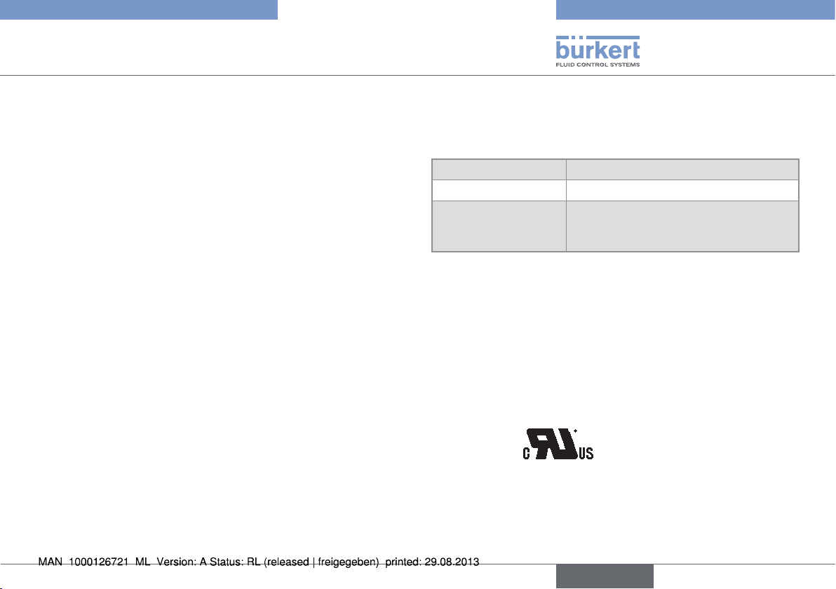
For UL devices (
Canada:
• UL 61010-1
• CAN/CSA-C22.2 n° 61010-1
) in the United States of America and
English
7
Page 8
Type 8026- 8036- 8076
Technical data
6.2.2. Conformity to the pressure directive
of flowmeters 8026 and fittings
S030 and S070
The devices 8026 and the fittings S030 and S070 comply with
article 3§3 of the pressure directive.
Acc. to the 97/23/CE pressure directive, the product can only be
used in the following cases (depending on max. pressure, pipe diameter and fluid):
Type of fluid Conditions
Fluid group 1, par.
1.3.a
Fluid group 2 par. 1.3.a DN ≤ 32
Fluid group 1 par. 1.3.b • Flowmeter 8026: DN ≤ 25
Fluid group 2 par. 1.3.b • Flowmeter 8026: DN ≤ 400
• Flowmeter 8026 and fitting S030:
DN
≤ 25 only
• Fitting S070: Forbidden
or DN > 32 and PNxDN
or DN > 25 and PNxDN ≤ 2000
• Fittings S030 and S070:
PNxDN ≤ 2000
• Fittings S030 and S070: DN
≤ 1000
≤ 200
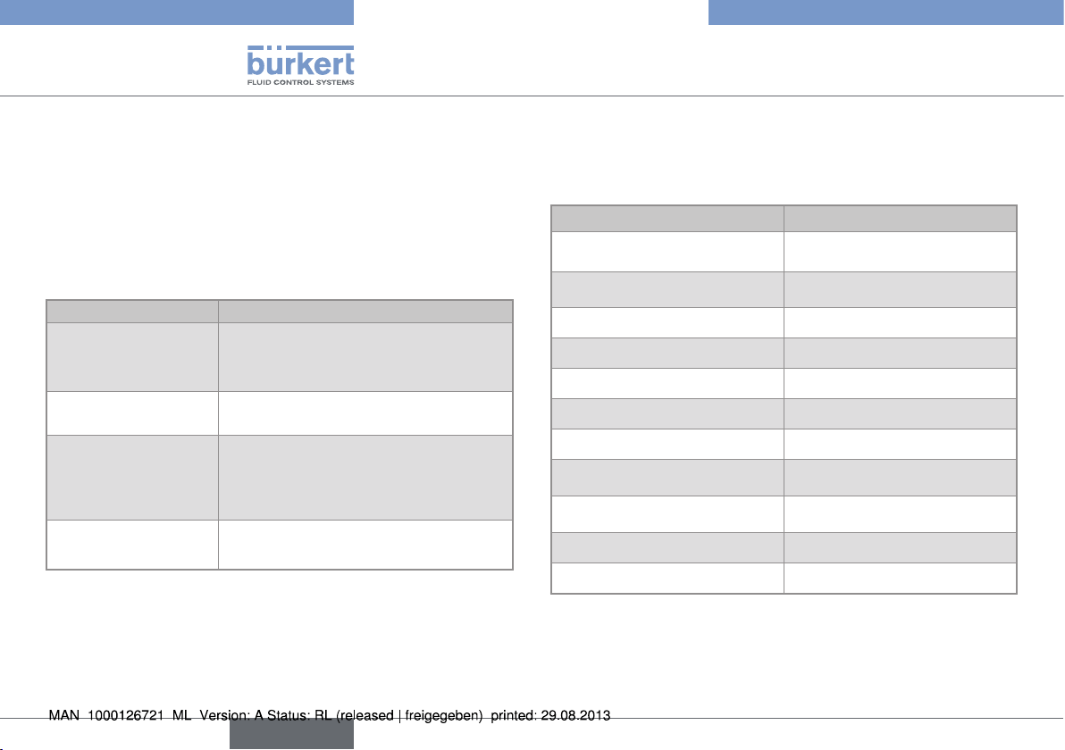
6.3. General technical data
6.3.1. Mechanical data
Part Material
Box / seals stainless steel 1.4404, PPS /
EPDM
Cover / seal PC / EPDM
Display module PC / PBT
M12 fixed connector nickel-plated brass
Fixed connector holder stainless steel 1.4404 (316L)
Screws Stainless steel
Nut PC
Flow sensor holder / seal (only
8026)
Axis and shaft of the paddle
wheel (only 8026)
Paddle wheel (only 8026) PVDF
Quarter-turn system (only SE36) PC
PVDF / FKM (default)
Ceramic (Al
2O3
)
8
English
Page 9
Type 8026- 8036- 8076
Technical data
Nickel-plated
brass
Stainless steel
PPS
FKM
PVDF
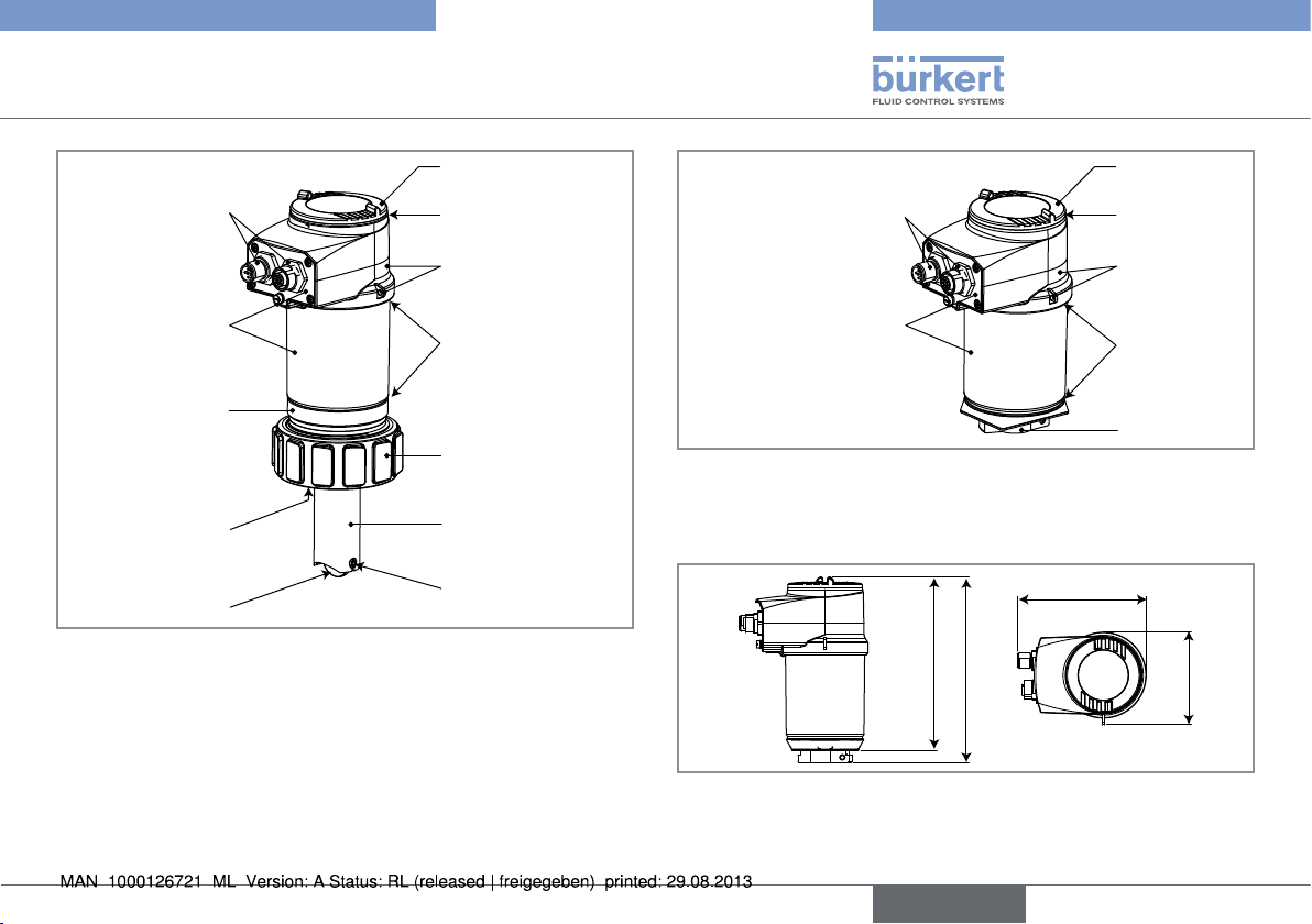
Fig. 2: Materials used in the 8026 fowmeters
PC
EPDM
PPS
EPDM
PC
PVDF
Ceramic (Al2O3)
PC
Nickel-plated
EPDM
brass
PPS
Stainless steel
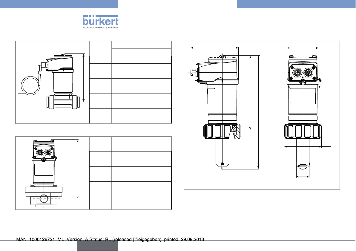
Fig. 3: Materials used in the SE36 electronic module for the
8036 or 8076 flowmeters
• Materials of the 8026 in contact with the fluid: PVDF, ceramic,
FKM (default).
131
140
Fig. 4: Dimensions of electronic module SE36
EPDM
PC
97
70
English
9
Page 10
Type 8026- 8036- 8076
Technical data
DN
06 160
08 160
15 165
H
20 163
25 163
32 166
40 170
50 177
65 177
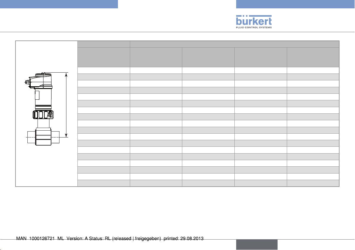
Fig. 5: Dimension H of flowmeter 8036
DN
15 166
25 181
H
40 198
50 216
80 256
100 257
Fig. 6: Dimension H of flowmeter 8076
H [mm]
with fitting S030
H [mm]
with fitting S070
97
151
1)
230 / 268,5
1)
with short sensor / with long sensor
Fig. 7: Dimensions of flowmeter 8026
Ø 65
70
Ø 75
Ø 26,5
10
English
Page 11
Type 8026- 8036- 8076
Technical data
DN of the fitting H [mm] with fitting S020 type:
[mm] T-fitting Flange fitting Plastic spigot Spigot or welding
15 231.5
20 229.5
25 229.5
32 232.5.
40 236.5
50 242.5 267.5 237.5
H
65 242.5 265.5 250.5 243.5
80 270.5 256.5 248.5
100 275.5 263.5 258.5
110 271.5
125 278.5 298.5 269.5
150 248.5 305.5 280.5
180 312.5
200 324.5 326.5 301.5
250 344.5 361.5
300 356.5 380.5
350 369.5 392.5
400 384.5
Fig. 8: Dimension H when the flowmeter 8026 is inserted into a fitting S020
tab in stainless
steel
English
11
Page 12
Type 8026- 8036- 8076
Technical data
A
P (bar)
10
9
8
7
6
5
4
3
2
1
0
A: Operating range
-10 +10 +30 +50 +70 +90 +110
PVDF +
PVC + PP
Metal
PVC (PN10)
PP (PN10)
Metal
(PN10)
PVDF (PN10)
T (°C)
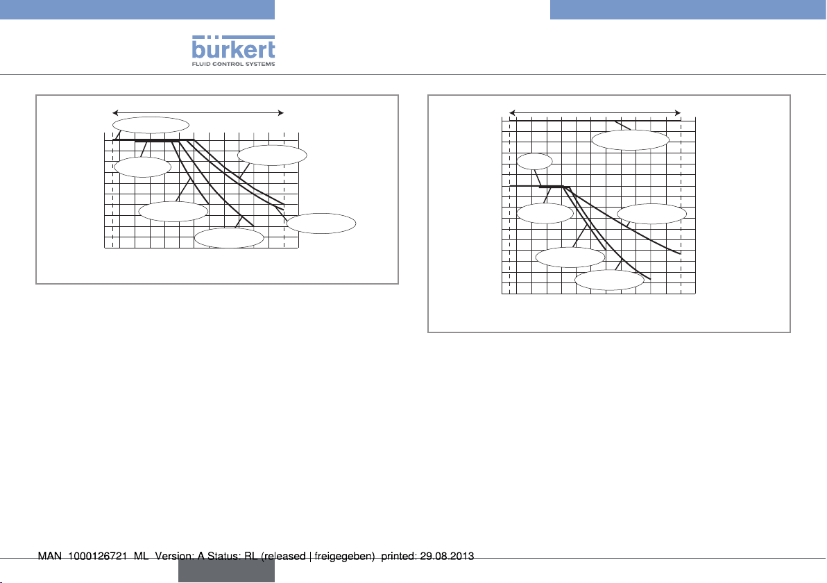
Fig. 9: Fluid temperature-pressure dependency for the flowmeter
8026 associated to a fitting S020
P (bar)
16
15
14
13
12
11
10
9
8
7
6
5
4
3
2
1
0
A: Operating range
PVDF
PVC + PP
PVC (PN10)
-10 +10 +30 +50 +70 +90 +110
A
Metal
PP (PN10)
(PN16)
PVDF (PN10)
T (°C)
Fig. 10: Fluid temperature-pressure dependency for the flowmeter
8036 (SE36 associated to a fitting S030 with PVDF
paddle wheel)
12
English
Page 13
Type 8026- 8036- 8076
Technical data
6.3.2. General data
Pipe diameter DN06 to DN400;
For a fitting S020 or S030 the appropriate diameter is determined using the flow rate / DN /
fluid velocity graphs: refer to the operating manuals of the fittings
Type of fitting • S020 for flowmeter 8026: see related operating manual
• S030 for flowmeter 8036: see related operating manual
• S070 for flowmeter 8076: see related operating manual
Fluid temperature
• 8026
• 8036 with fitting S030 in PVC
1)
• 8036 with fitting S030 in PP 1)
1)
• 8036 with fitting S030 in PVDF
stainless steel
1)
, brass1) or
• 8076 with fitting S070 in aluminium
• 8076 with fitting S070 in stainless steel
• -15 to +100 °C; Also factor in the fluid temperature/pressure dependency for the 8026
inserted into an S020 fitting: see „Fig. 9“
• 0 to +50 °C; Also factor in the fluid temperature/pressure dependency for the 8036: see
„Fig. 10“
• 0 to +80 °C; Also factor in the fluid temperature/pressure dependency for the 8036: see
„Fig. 10“
• -15 to +80 °C; Also factor in the fluid temperature/pressure dependency for the 8036:
see „Fig. 10“
• max. +80 °C
• max. +100 °C
English
13
Page 14
Type 8026- 8036- 8076
Technical data
Fluid pressure
• 8026
• 8036
• 8076 with a fitting S070 of DN15
• 8076 with a fitting S070 of DN25
• 8076 with a fitting S070 of DN40 or DN50
• 8076 with a fitting S070 of DN80
• 8076 with a fitting S070 of DN100
Type of fluid
• 8026 and 8036
• 8076
Fluid viscosity
• 8026 and 8036
• 8076
Solid particle rate in the fluid
• 8026 and 8036
• 8076
Also refer to the requirements of the Pressure Directive: see chap. „6.2.2“
• PN10; Also factor in the fluid temperature/pressure dependency for the 8026 inserted
into an S020 fitting (see „Fig. 9“)
• PN16; Also factor in the fluid temperature/pressure dependency for the 8036 (SE36
mounted on an S030 fitting): see „Fig. 10“
• max. 55 bar
• max. 55 bar (or the rules governing the flanges)
• max. 18 bar
• max. 12 bar
• max. 10 bar
• Neutral or slightly aggressive fluids
• Viscous fluids, free of solid particles
• 300 cSt max.
• Refer to the operating manual for fitting S070
• ≤ 1%
• 0 %
14
English
Page 15
Type 8026- 8036- 8076
Technical data
Flow rate measurement
• Measurement range
• Linearity
• Repeatability
• Measurement error with standard K factor
• measurement error with a Teach-in procedure
1)
and PVDF paddle wheel
2)
Determined in the following reference conditions: fluid = water, water and ambiant temperatures = 20 °C, upstream and downstream dis-
• 0,3 to 10 m/s
2)
• ±0,5%
• ±0,4%
• ±2,5%
• ±1%
of the full scale
2)
of the measured value
2)
of the measured value
2)
of the measured value (at the teach-in point)
tances respected, appropriate pipe dimensions.
6.3.3. Electrical data
Power supply
• version with 2 or 3 outputs (2 wires)
• version with 4 outputs (3 wires)
Specifications of the power source (not sup-
plied) of the UL devices
Current consumption
• version with 2 or 3 outputs (2 wires)
• version with 4 outputs (3 wires)
Current consumption, with loads on the
transistors
Power consumption 40 W max.
Protection against polarity reversal
• 14-36 V DC, filtered and regulated
• 12-36 V DC, filtered and regulated
• limited energy source (in accordance to UL 61010-1, paragraph 9.3)
• or Class 2 source (in accordance to standards 1310/1585 and 60950-1)
• 25 mA max. (at 14 V DC)
• 5 mA max. (at 12 V DC)
1 A max.
yes
English
15
Page 16
Type 8026- 8036- 8076
Technical data
Protection against voltage spikes
Protection against short circuits
Transistor output
• Version with only 1 transistor output
• Version with 2 transistor outputs
Current output
• Version with only 1 current output (2 wires)
• version with 2 current outputs (3 wires)
yes
yes, transistor outputs
• NPN, open collector, 700 mA max., 1-36 V DC
• NPN (/sink) or PNP (/source) (depending on parameter setting), open collector, 700 mA
max., 500 mA max. per transistor if both transistor outputs are wired.
NPN output: 1-36 V DC
PNP output: supply voltage
4-20 mA, sink ("NPN sink") or source ("PNP source") (depending on parameter setting)
• max. loop impedance: 1100
• max. loop impedance: 1100
W at 36 V DC, 610 W at 24 V DC, 180 W at 14 V DC
W at 36 V DC, 610 W at 24 V DC, 100 W at 12 V DC
16
English
Page 17
Type 8026- 8036- 8076
Installation and wiring
7. INSTALLATION AND WIRING
7.1. Safety instructions
danger
Risk of injury due to high pressure in the installation.
• Stop the circulation of fluid, cut off the pressure and drain the
pipe before loosening the process connections.
Risk of injury due to electrical voltage.
• Shut down and isolate the electrical power source before
carrying out work on the system.
• Observe all applicable accident protection and safety regulations for electrical equipment.
Risk of injury due to the nature of the fluid.
• Respect the prevailing regulations on accident prevention and
safety relating to the use of aggressive fluids.
Warning
Risk of injury due to non-conforming installation.
• The electrical and fluid installation can only be carried out by
qualified and skilled staff with the appropriate tools.
• Install appropriate safety devices (correctly rated fuse and/or
circuit-breaker).
• Respect the assembly instructions for the fitting used.
Risk of injury due to unintentional switch on of power supply
or uncontrolled restarting of the installation.
• Take appropriate measures to avoid unintentional activation of
the installation.
• Guarantee a set or controlled restarting of the process subsequent to any intervention on the device.
note
The tightness of the device is not guaranteed when the cover
is removed.
• Once the cover is removed, prevent the projection of liquid
inside the housing.
The device may be damaged if a metal component comes
into contact with the electronics.
• Prevent contact of the electronics with a metal component
(screwdriver, for example).
English
17
Page 18
Type 8026- 8036- 8076
Installation and wiring
7.2. Installation onto the pipe
danger
Risk of injury due to high pressure in the installation.
• Stop the circulation of fluid, cut off the pressure and drain the
pipe before loosening the process connections.
Risk of injury due to the nature of the fluid.
• Respect the prevailing regulations on accident prevention and
safety relating to the use of aggressive fluids.
7.2.1. Recommendations on installing an
8026 or an 8036 on a pipe
attention
Risk of damage when installing the fitting.
• Respect the installation instructions given in the user manual for
the fitting.
→ Install the fitting on the pipe, respecting the instructions given in
the manual for the fitting used.
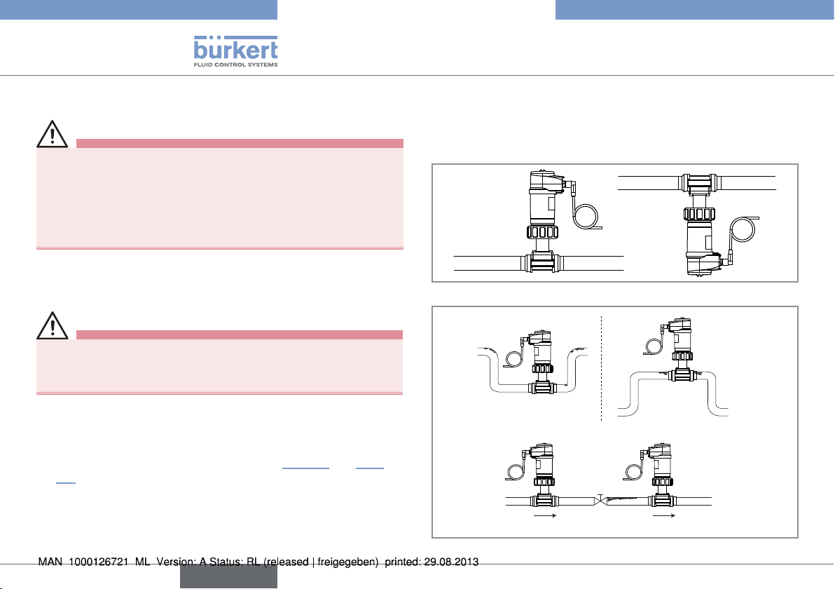
→ Respect the following additional conditions of installation to
ensure that the device operates correctly („Fig. 11“ and „Fig.
12“).
- Install the device in such a way that the paddle wheel axis is
horizontal.
- Prevent the formation of air bubbles in the pipe in the section
around the sensor.
- Ensure that the pipe is always filled in the section around the
sensor.
Fig. 11: The paddle wheel axis must be horizontal
Correct
Correct
Incorrect
Incorrect
flow direction
18
English
Page 19
Type 8026- 8036- 8076
Installation and wiring
Correct
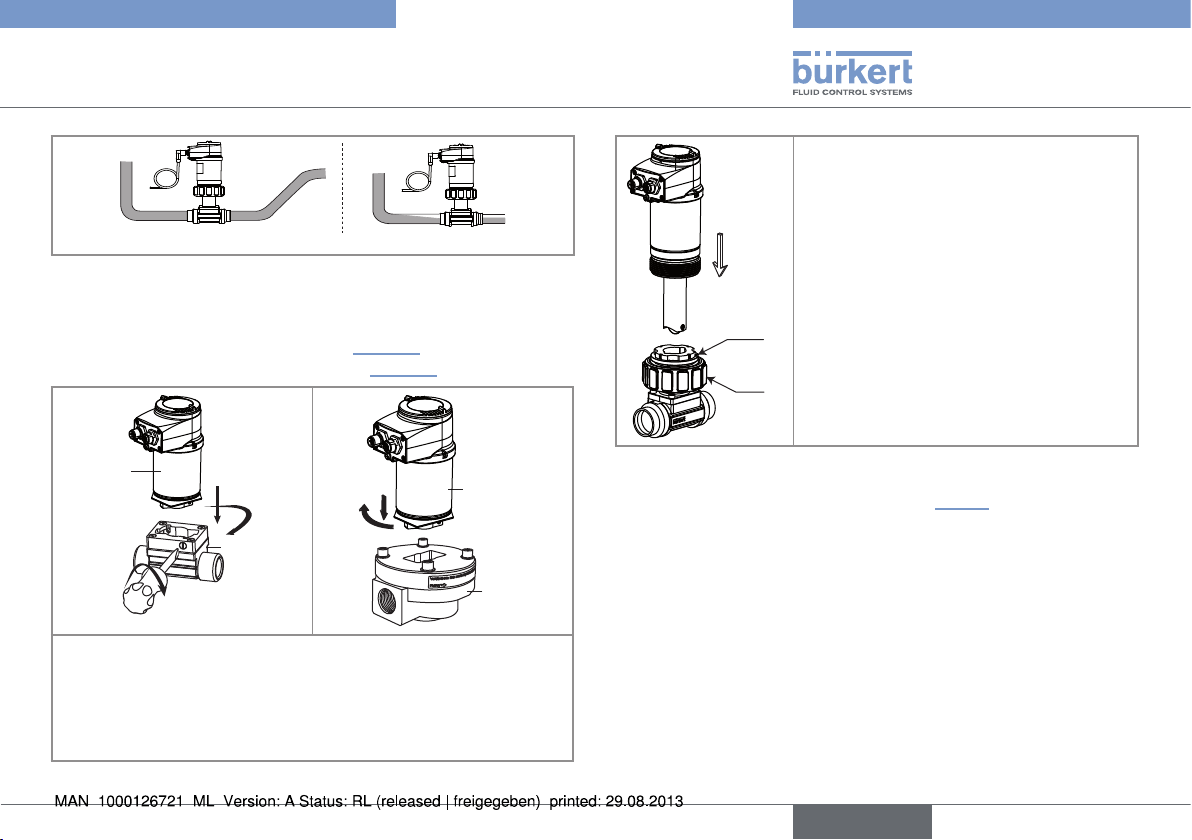
Fig. 12: Air bubbles within the pipe / Filling of the pipe
Incorrect
→ Fit the display module (see related operating manual) to para-
meter the device.
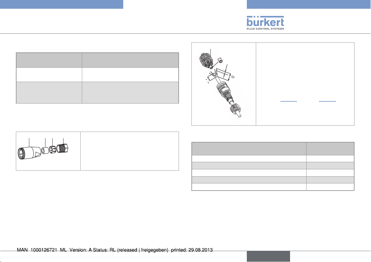
→ Assemble the flowmeter 8036 (see „Fig. 13“) or install the flow-
meter 8026 into the fitting S020 (see „Fig. 14“)
→ Check that there is a seal on the fitting
and that it is not damaged. Replace the
seal if necessary.
→ Place nut A on the fitting and insert
circlip B into the groove.
→ Carefully insert the device into the
fitting. If assembly is correct, the device
can no longer rotate on itself.
→ Secure the unit with nut A, tightening
B
only by hand.
A
SE36
1
2
S030
3
1
2
SE36
S070
→ 1 : Insert the electronic module in the sensor holder.
→ 2 : Turn the electronic module by a quarter turn.
→ 3 : Secure the electronic module and the S030 fitting only, by
tightening the screw with a suitable tool to a max. tightening
torque of 1 Nm.
Fig. 13: Assembling the SE36 and the fitting S030 or S070
Fig. 14: Installation of flowmeter 8026 into the fitting S020
→ Set the K factor parameter (see chap. „8.8.8“) or have it deter-
mined through a teach-in procedure.
English
19
Page 20
Type 8026- 8036- 8076
Installation and wiring
7.2.2. Recommendations on installing an
8076 on a pipe
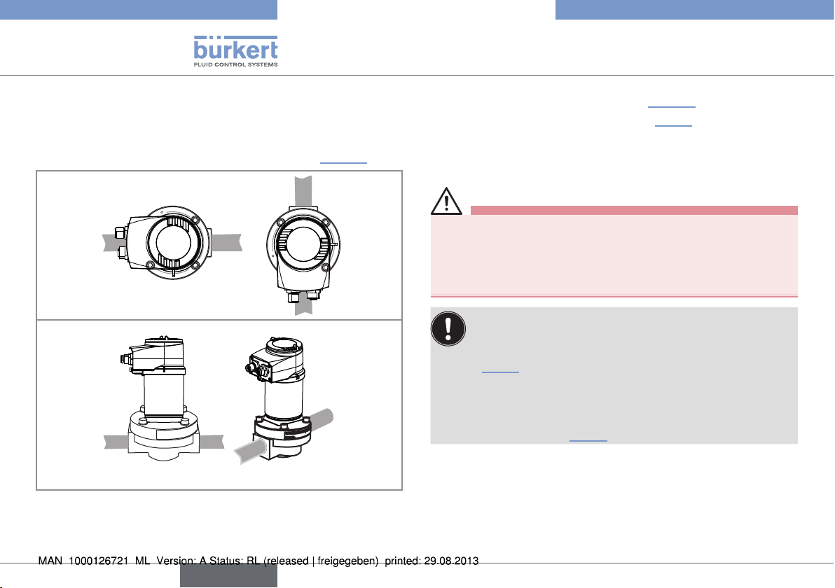
→ Install the fitting S070 on the pipe in such a way that the oval
gear axes are in the horizontal plane, as shown in „Fig. 15“.
Fig. 15: The oval gear axes must be horizontal (seen from the front)
Correct
Incorrect
→ Fit the display module (see related operating manual) to para-
meter the device.
→ Assemble flowmeter type 8076 (see „Fig. 13“)
→ Set the K factor parameter (see chap. „8.8.8“) or have it deter-
mined through a teach-in procedure.
7.3. Wiring
danger
Risk of injury due to electrical voltage.
• Shut down and isolate the electrical power source before
carrying out work on the system.
• Observe all applicable accident protection and safety regulations for electrical equipment.
• Use a high quality electrical power supply (filtered and
regulated).
• Make sure the installation is equipotential. See chap.
„7.3.3“.
• Use a shielded cable.
• Once the device is wired, set the "HWMode" parameter
depending on the wiring carried out, sink/NPN or source/
PNP. See chap. „8.8.3“.
20
English
Page 21
Type 8026- 8036- 8076
5,5
Installation and wiring
7.3.1. Electrical connections
Number of fixed
connectors
1 male M12 fixed
connector
1 male M12 fixed connector and 1 female M12
fixed connector
Type of connectors
female 5-pin M12 (available as an
accessory)
female 5-pin M12 + male 5-pin M12
(both available as accessories)
7.3.2. Assembling the male or female
connector (accessories:
4 3 2 1
→ Unscrew the nut [1] on the body [4].
→ Insert the cable into the nut [1], the
cable clamp [2] and the seal [3], and
then into the body [4].
5
→ Strip 20 mm of the cable.
→ Cut the central wire (earth) so that
its length is equal to 11.5 mm.
11,5
5,5
20
→ Expose 5.5 mm of the wires on the
stripped cable.
→ Insert each wire into the appropriate
pin on the terminal block [5] (see
chap. „7.3.4“ to chap. „7.3.6“).
→ Tighten the terminal block [5] wired
to the body [4].
→ Tighten the connector nut [1].
Fig. 16: Multipin M12 connector (available as an accessory)
Pin of the female M12 connector available
as an accessory (order code 438680)
1 brown
2 white
3 blue
4 black
5
Colour of the
wire
grey
English
21
Page 22
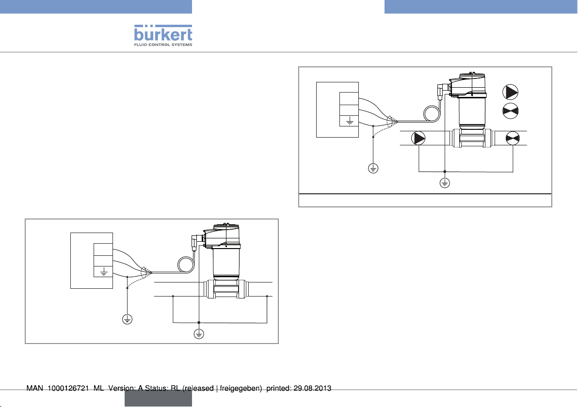
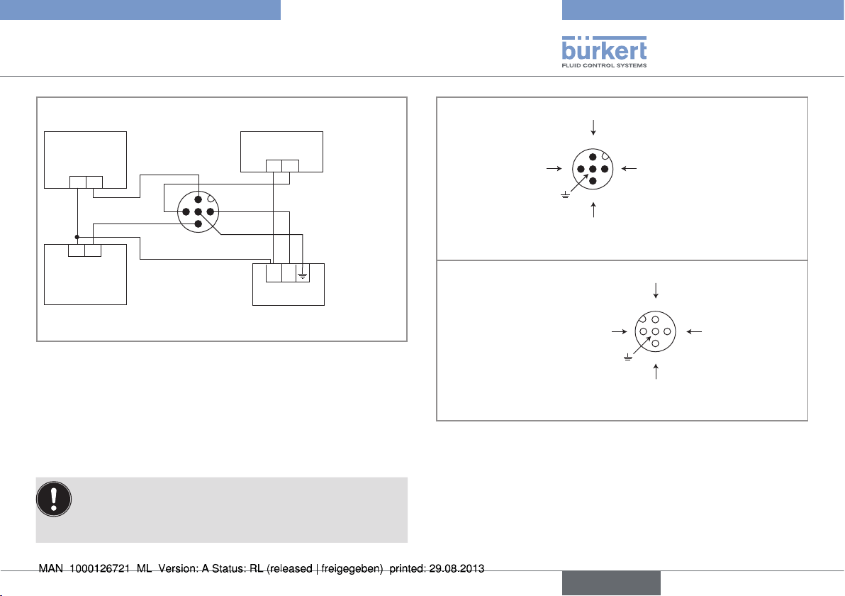
7.3.3. Equipotentiality of the installation
To ensure the equipotentiality of the installation (power supply device - fluid):
→ Connect together the various earth spots in the installation to
eliminate the potential differences that may occur between different earthes.
→ Observe faultless grounding of the shield of the power supply
cable.
→ Special attention has to be paid if the device is installed on
plastic pipes because there is no direct earthing possible.
Proper earthing is performed by earthing together the metallic
devices such as pumps or valves, that are as close as possible
to the device.
Type 8026- 8036- 8076
Installation and wiring
+
12-36 V DC
Power supply
Devices such as valves, pumps,...
Fig. 18: Equipotentiality skeleton diagram with pipes in plastic
1)
Power
supply
Fig. 17: Equipotentiality skeleton diagram with pipes in metal
22
+
12-36 V DC
English
Page 23
Type 8026- 8036- 8076
Installation and wiring
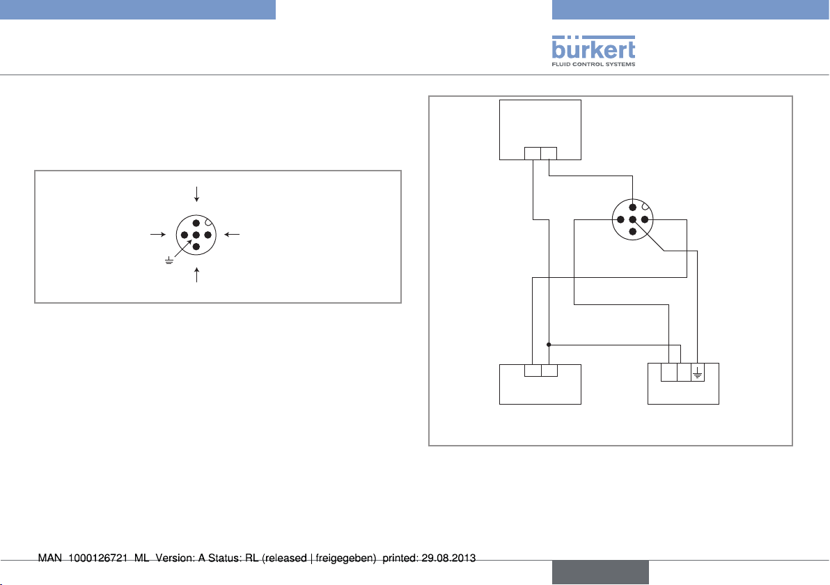
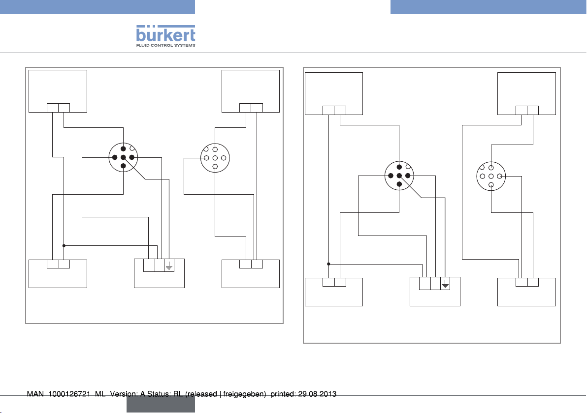
7.3.4. Wiring a version with a single
M12 fixed connector and an NPN
transistor output and a current
output
NPN transistor output (TR1)
Load
white
2
0V
3
4
V+ (14-36 V DC)
1
Not connected
Fig. 19: Pin assignment of the male fixed connector on a version
with 1 NPN transistor output and 1 current output
2
blue
3
brown
1
4
grey
+ -
4-20 mA input (external
Power supply
+ -
14-36 VDC
instrument)
Fig. 20: Wiring the NPN transistor output and the current output
in sinking mode (parameter setting "NPN/sink", cannot
be changed), on a version with 1 M12 fixed connector, 1
NPN transistor output and 1 current output
English
23
Page 24
Type 8026- 8036- 8076
Installation and wiring
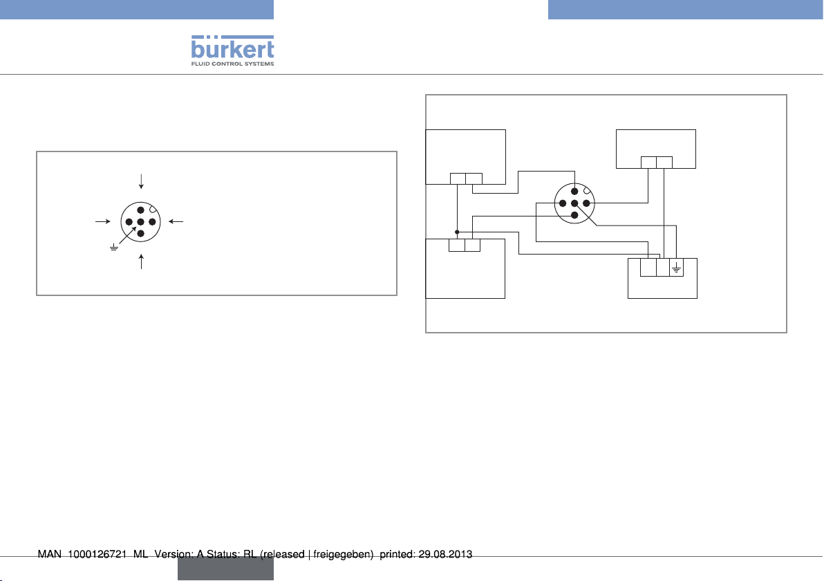
7.3.5. Wiring a version with a single M12
fixed connector and two transistor
outputs and one current output
Transistor output 1 (TR1)
2
0V
3
4
Transistor output 2 (TR2)
Fig. 21: Pin assignment of the male fixed connector on a version
with 2 transistor outputs and 1 current output
V+ (14-36 V DC)
1
4-20 mA input (external
Load 1
black
white
2
3
4
1
brown
grey
instrument)
+ -
blue
+ -
14-36 V DC
Load 2
Power supply
Fig. 22: NPN wiring of both transistor outputs and wiring the
current output in sinking mode (parameter setting "NPN/
sink"), of a version with 1 M12 fixed connector
24
English
Page 25
Type 8026- 8036- 8076
Installation and wiring
4-20 mA input (external
instrument)
Load 1
+ -
+ -
14-36 V DC
Load 2
black
white
blue
2
brown
3
1
4
grey
Power supply
Fig. 23: PNP wiring of both transistor outputs and wiring the
current output in sourcing mode (parameter setting "PNP/
source"), of a version with 1 M12 fixed connector
7.3.6. Wiring a version with two M12 fixed
connectors and two transistor
outputs and two current outputs
Connect the power supply for the device to the male
fixed connector; the supply is then transferred internally
to pins 1 and 3 of the female fixed connector in order to
ease wiring of the load to the female fixed connector.
Transistor output 1 (TR1)
2
V+ (12-36 V DC)
0V
3
1
4
Current output 1 (AC1)
Male fixed connector
Transistor output 2 (TR2)
2
V+ (12-36 V DC)
1
4
0V
3
Current output 2 (AC2)
Female fixed connector
Fig. 24: Pin assignment of the male and female M12 fixed
connectors
English
25
Page 26
Type 8026- 8036- 8076
Installation and wiring
Load 1
+ - + -
1st 4-20 mA input
(external instru-
ment)
black
white
2
3
blue
brown
1
4
grey
12-36 V DC
Power supply
brown
1
+ -
white
2
3
4
black
nd
2
4-20 mA
input (external
instrument)
Load 2
Fig. 25: NPN wiring of both transistor outputs and wiring of both
current outputs in sinking mode, on a version with 2 fixed
connectors (parameter setting "NPN/sink")
Load 1
Load 2
white
white
3
black
2
brown
1
4
grey
+ -
blue
+ - + -
12-36 V DC
1st 4-20 mA input
(external instru-
ment)
Power supply
Fig. 26: PNP wiring of both transistor outputs and wiring of both
current outputs in sourcing mode, on a version with 2
fixed connectors (parameter setting "PNP/source")
2
blue
3
1
4
black
nd
2
4-20 mA input
(external instrument)
26
English
Page 27
Type 8026- 8036- 8076
Adjustment and commissioning
8. ADJUSTMENT AND COMMISSIONING
8.1. Safety instructions
Warning
Risk of injury due to non-conforming adjustment.
Non-conforming operating could lead to injuries and damage the
device and its surroundings.
• The operators in charge of adjustment must have read and
understood the contents of this manual.
• In particular, observe the safety recommendations and intended
use.
• The device/installation must only be adjusted by suitably trained
staff.
Warning
Danger due to nonconforming commissioning.
Nonconforming commissioning could lead to injuries and damage
the device and its surroundings.
• Before commissioning, make sure that the staff in charge have
read and fully understood the contents of the manual.
• In particular, observe the safety recommendations and intended
use.
• The device / the installation must only be commissioned by
suitably trained staff.
Protect this device against electromagnetic interference, ultraviolet rays and, when installed outdoors, the
effects of the climatic conditions.
8.2. When switching on the device
If the message “ERROR - This display does not support this
Element - Contact Bürkert” is displayed, the version of the
display module is not compatible with the software version
of the device. Contact your Bürkert reseller.
When the device is switched on or the display module mounted on
the electronic module, the display indicates the software version of
the display. The display then shows the first screen of the Process
level.
8.3. Operating levels
The device has 2 operating levels:
Process level
This level is used:
• to read the value of the measured flow rate and/or the sensor
input frequency
• to read the values of both volume totalizers
• to reset totalizer 2
• to read both the lowest and highest values of the flow rate or the
input frequency that have been measured by the device since the
latest reset (this feature is not active by default),
English
27
Page 28
Type 8026- 8036- 8076
Adjustment and commissioning
• to reset both the lowest and highest values of the flow rate or the
input frequency, if the feature has been activated
• to read the current values emitted on the 4-20 mA outputs.
Configuration level
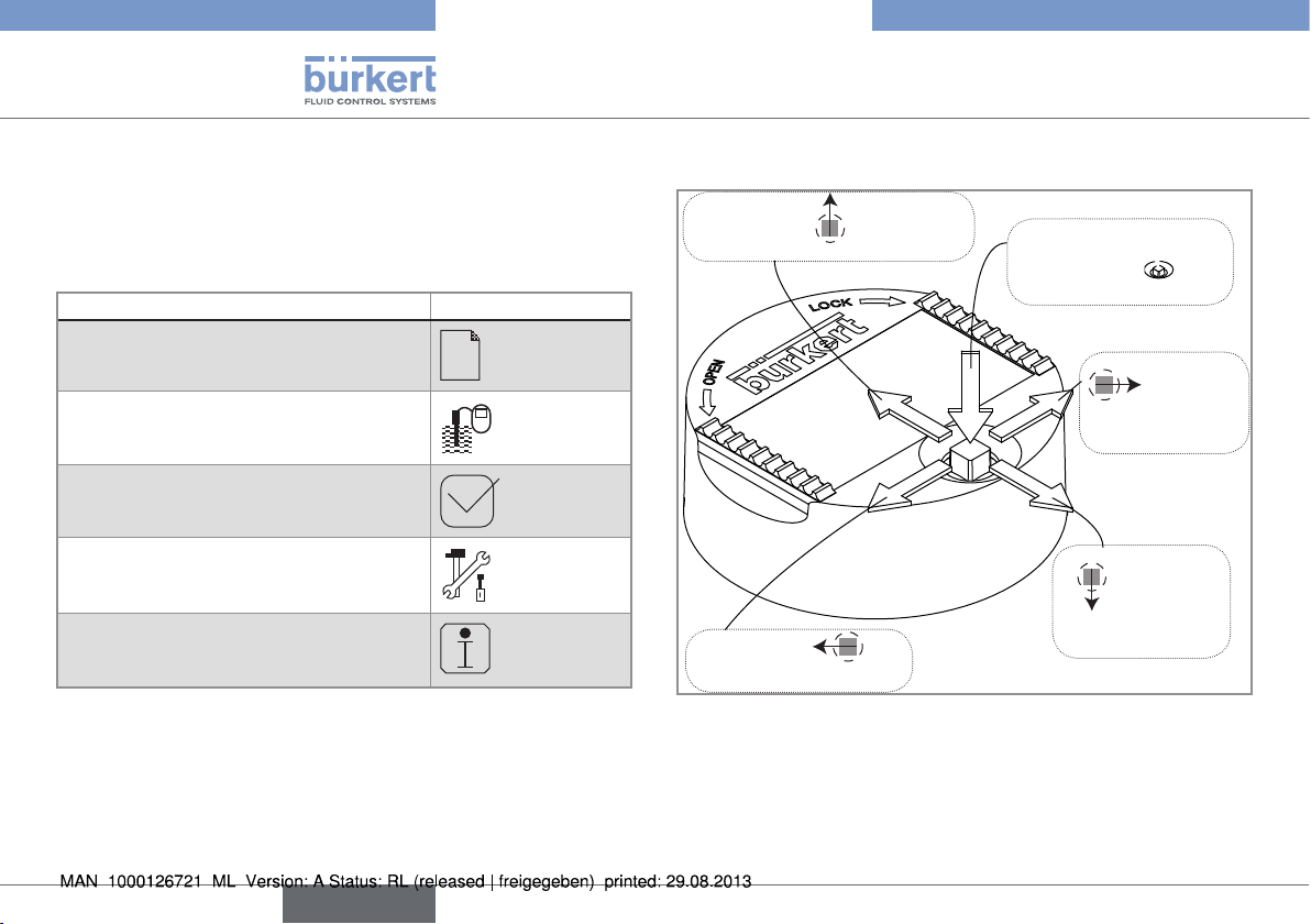
This level comprises 5 menus:
Menu title Relevant icon
"Param"
Default access code is "0000".
This is
when the
device is being parame-
tered............
....................
"Calib"
Default access code is "0000".
"Diagnostic"
Default access code is "0000".
"Test"
Default access code is "0000".
"Info"
8.4. Using the navigation button
Symbolised by in this manual
Symbolised by
this manual
Symbolised by
in this manual
Symbolised by
in this manual
Symbolised by in
this manual
Fig. 27: Using the navigation button
in
28
English
Page 29
Type 8026- 8036- 8076
Adjustment and commissioning
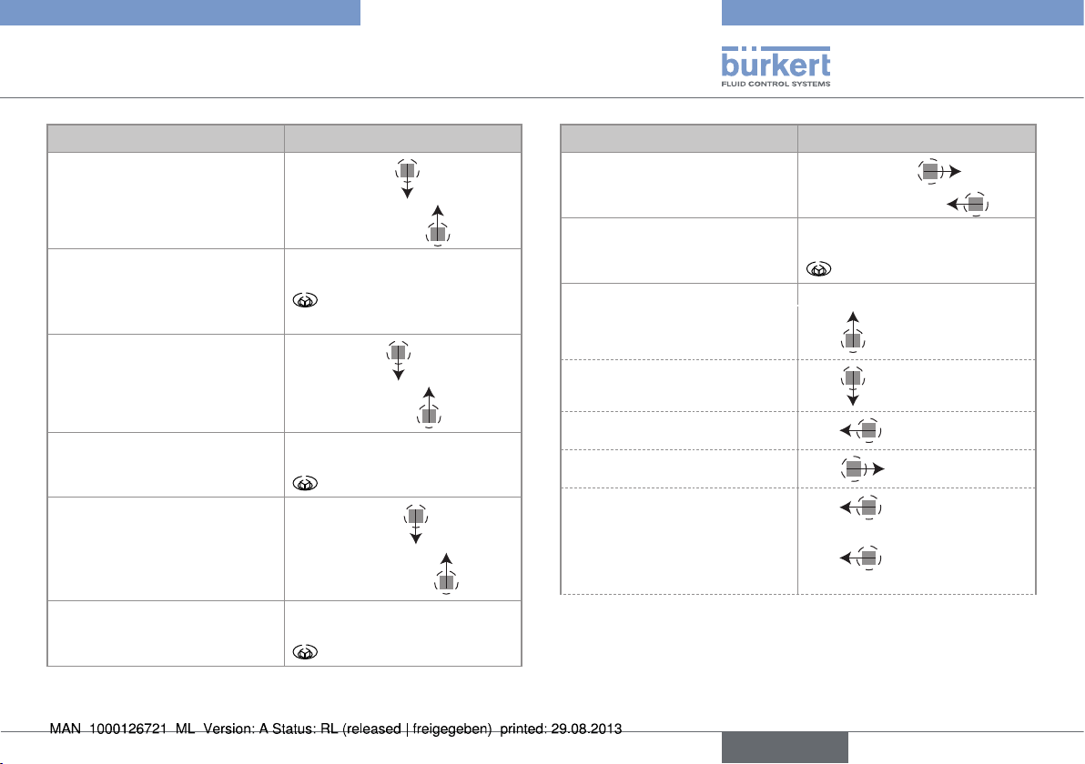
You want to... Press...
...browse in Read level
• next screen:
• previous screen:
• ...access the Configuration
level
• ...display the Param menu
...browse in the menus of the
Configuration level
...access the menu displayed
...browse in the menu functions
...select the highlighted function
for at least 2 sec., from any
screen of the Read level
• next menu:
• previous menu:
• next function:
• previous function:
You want to... Press...
...browse in the dynamic
functions bar (MEAS, BACK,
ABORT, OK, YES, NO)
...confirm the highlighted
dynamic function
...modify a numerical value
- increment the figure
selected
- decrement the figure
selected
- select the previous figure
- select the next figure
- allocate the "+" or "-" sign
to the numerical value
• next function:
• previous function:
-
-
-
-
of the numerical value then
sign is displayed
to the extreme left
until the desired
English
29
Page 30
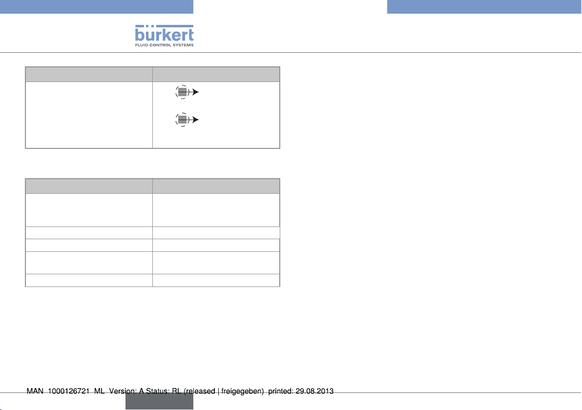
You want to... Press...
- move the decimal point
-
to the extreme right
of the numerical value then
until the decimal
point is in the desired
place
8.5. Using the dynamic functions
You want to... Choose...
...go back to the READ level,
without validating the modifications made
...confirm the entering dynamic function "OK"
...go back to the parent menu dynamic function "BACK"
...abort the current operation
and go back to the parent menu
...answer the question asked dynamic function "YES" or "NO"
dynamic function "MEAS"
dynamic function "ABORT"
Type 8026- 8036- 8076
Adjustment and commissioning
30
English
Page 31

Type 8026- 8036- 8076
Adjustment and commissioning
8.6. Description of icons and LEDs
• The LEDs of the display module are duplicated on the electronic board that is located under the display module: these LEDs
become visible when the device is not equipped with the display module.
• The yellow LED related to a transistor output is deactivated if the transistor output is configured in pulse mode ("Pulse").
The LEDs of the display module are duplicated on the electronic board that is located under the display module: these LEDs become
visible when the device is not equipped with the display module.
L
O
C
600.0l/h
0.60/h
K
Yellow LED: shows that
transistor 1 is switched
not used
Green LED: shows that
the device is energized
Red LED: shows
an error.
O
Flow_L
Flow_m3
ERR
N
E
P
Yellow LED: shows that transis-
tor 1 is switched
Yellow LED: shows that transistor 2
is switched
Fig. 28: Position of the icons and description of the LEDs
Yellow LED: shows that
transistor 2 is switched
English
Red LED: shows an error.
31
Page 32

Type 8026- 8036- 8076
Adjustment and commissioning
Icon Possible cause and alternatives
Sensor input frequency within the defined ranges
The alternatives, in this position, if monitoring of the
sensor input frequency is activated, are:
, associated with
•
ERR
ERR
• , associated with
The device is measuring.
The alternative icons in this position are:
!
HOLD
•
flashing: HOLD mode activated.
• T: running check that the outputs are working and
behaving correctly.
"warning" message.
"error" message.
8.7. Process level
A
First view of the Pro-
cess level.
Zoom on the value
Flow_L
Flow_m3
Flow_L
in the first line.
1243
Zoom on the value in
the second line.
Flow_m3
1.243
Display of the main
volume totalizer.
Tot1_L
987654
1243l/h
1) 2)
1. 243/h
1)
l/h
1) 2)
/h
32
B
English
Page 33

Type 8026- 8036- 8076
Adjustment and commissioning
B
Display of the
second volume tota-
lizer.
Display of the minimum and maximum
input flows or fre-
quencies measured.
Display of the cur-
rent outputs.
Tot2_m
Max
Min
AC1
AC2
3
987
1250l/h
1200l/h
18.3 mA
7.5 mA
C
3)
Reset Yes/No
Reset Yes/No
C
Zoom on the value
AC1
of the first current
output.
Zoom on the value
18.3 mA
AC2
of the second cur-
rent output.
1)
These displays appear if line 1 and line 2 are activated. Only line 1
is activated by default.
2)
Only the time unit is displayed when the PVAR chosen is "Flow_
m3", "Flow_gal" or "Flow_Igal".
3)
Display of the minimum and maximum flow rates in the Process
level is deactivated by default.
7.5 mA
A
English
33
Page 34

Type 8026- 8036- 8076
Adjustment and commissioning
8.8. Configuration level
Only the most current functions are described in the Quickstart. For the use of the other functions, refer to the operating manual available on the CD delivered with the device.
8.8.1. Setting the data displayed on lines 1 and 2 of the display module
Param
This is
when the
device is being parame-
tered............
....................
Display
This is
when the
device is being parame-
tered............
....................
Line1 / Line2
Line 1/Line2:
PVar:
Unit:
Enabled
Disabled
Flow_L
Flow_m3
Flow_gal
Flow_Igal
Freq.
/h
/min
/s
Hz
If PVar ≠ Freq.
If PVar = Freq.
34
English
Filter:
Slow
Fast
None
Page 35

Type 8026- 8036- 8076
Adjustment and commissioning
8.8.2. Choosing the units for the totalizers displayed in Process level
The totalizers are saved if a power cut occurs.
Param
This is
when the
device is being parame-
tered............
....................
Display
This is
when the
device is being parame-
tered............
....................
Totalizers Total1 / Total 2
Unit
Liter
m3
gal
Igal
8.8.3. Defining the connection mode of the outputs
Param
This is
when the
device is being parame-
tered............
....................
On a version of the device with an NPN transistor output and a current output, only the choice “sink/NPN” is possible.
The setting has no effect on a version with one fixed connector, 2 transistor outputs and a single current output, if the sole current
output is wired.
Outputs
This is
when the
device is being parame-
tered............
....................
HWMode
sinkNPN
sourcePNP
English
35
Page 36

8.8.4. Setting the parameters of the current outputs
Param
This is
when the
device is being parame-
tered............
....................
Outputs
This is
when the
device is being parame-
tered............
....................
AC1 / AC2
PVar:
Flow_L
Flow_m3
Flow_gal
Flow_Igal
Freq.
Tot1_L
Tot1_m3
Tot1_gal
Tot1_Igal
Tot2_L
Tot2_m3
Tot2_gal
Tot2_Igal
4mA: INPUT
20mA: INPUT
Filter:
Slow
Fast
None
Diag. mode:
None
22mA
Type 8026- 8036- 8076
Adjustment and commissioning
36
English
Page 37

Type 8026- 8036- 8076
Adjustment and commissioning
8.8.5. Setting the parameters of the transistor outputs
The 2nd transistor output "TR2" is only available on a version with 2 transistor outputs.
Param
This is
when the
device is being parame-
tered............
....................
Outputs
This is
when the
device is being parame-
tered............
....................
TR1 / TR2 PVar:
Mode: Hysteresis
Low: INPUT
High: INPUT
Contact:
Delay: INPUT
Pulse: INPUT
Flow_L
Flow_m3
Flow_gal
Flow_Igal
Freq.
Tot1_L
Tot1_m3
Tot1_gal
Tot1_Igal
Tot2_L
Tot2_m3
Tot2_gal
Tot2_Igal
Warning
Window
Pulse
Normally open
Normally closed
If "Mode" ≠ "Pulse"
If "PVar" ≠ "Warning"
If "Mode" ≠ "Pulse"
If "Mode" = "Pulse"
English
37
Page 38

Type 8026- 8036- 8076
Adjustment and commissioning
8.8.6. Activating/deactivating the Hold function
• The Hold mode is automatically deactivated when the device restarts after a power interruption, if the Hold mode was activated at
the moment of the power cut-off.
• The Hold mode has no effect on the transistor outputs when they are operating in “Pulse” mode.
Calib
System
Hold
Hold: Disable
Hold: Enable
8.8.7. Adjusting the current outputs
Warning
Risk of injury due to wrong adjustment.
• Make sure the Hold mode is disabled (see chap. „8.8.6“).
Calib
Outputs
AC1 / AC2
4mA:
20mA:
The entered values are not memorised in this menu. Only the values emitted on the current outputs are adjusted after pressing “OK”
when the message “Recalibrate AC outputs?” is shown.
38
English
INPUT
INPUT
Page 39

Type 8026- 8036- 8076
Adjustment and commissioning
8.8.8. Entering the K factor or determining it with Teach-in
Calib
Sensor
K.fact.
INPUT
Vol.Teach
Flow Teach
PVar:
Start Teach
PVar:
Start Teach
Litre
m3
gal
Igal
Meas.Progress
Input Vol.
Cal. Result
Flow_L
Flow_m3
Flow_gal
Flow_Igal
Freq.
Measure
Flow Teach
Cal. Result
English
39
Page 40

Type 8026- 8036- 8076
Maintenance and troubleshooting
9. MAINTENANCE AND TROUBLESHOOTING
9.1. Safety instructions
danger
Risk of injury due to high pressure in the installation.
Risk of injury due to electrical voltage.
Risk of injury due to high temperatures of the fluid.
Risk of injury due to the nature of the fluid.
Warning
Risk of injury due to non-conforming maintenance.
• Maintenance must only be carried out by qualified and skilled
staff with the appropriate tools.
• Ensure that the restart of the installation is controlled after any
interventions.
→ To clean the device and the flow sensor, refer to the operating
manual available on the CD delivered with the device.
9.2. If you encounter problems
→ If you encounter problems, refer to the operating manual avai-
lable on the CD delivered with the device.
10. PACKAGING, TRANSPORT
note
Damage due to transport
Transport may damage an insufficiently protected device.
• Transport the device in shock-resistant packaging and away
from humidity and dirt.
• Do not expose the device to temperatures that may exceed the
admissible storage temperature range.
• Protect the electrical interfaces using protective plugs.
11. STORAGE
note
Poor storage can damage the device.
• Store the device in a dry place away from dust.
• Storing temperature for type 8026: -10 to +60°C.
• Storing temperature for type SE36: -10 to +60°C.
• Storing temperature for the fitting: refer to the related manual
40
English
Page 41

Type 8026- 8036- 8076
Disposal of the product
12. DISPOSAL OF THE PRODUCT
→
Dispose of the device and its packaging in an environmentallyfriendly way.
note
Damage to the environment caused by products contaminated by fluids.
• Keep to the existing provisions on the subject of waste disposal
and environmental protection.
note
Comply with the national and/or local regulations which
concern the area of waste disposal.
English
41
Page 42

Type 8026- 8036- 8076
42
English
Page 43

Typ 8026 - 8036 - 8076
Durchfluss-Messgeräte mit Flügelrad
Quickstart
Deutsch
Page 44

We reserve the right to make technical changes without notice.
Technische Änderungen vorbehalten.
Sous réserve de modifications techniques.
© 2009-2012 Bürkert SAS
Quickstart 1207/1_EU-ML_00561813_original_FR
1. ÜBER DEN QUICKSTART ...........................................................................3
2. BESTIMMUNGSGEMÄSSE VERWENDUNG ......................................4
3. GRUNDLEGENDE SICHERHEITSHINWEISE ....................................4
4. ALLGEMEINE HINWEISE .............................................................................6
5. BESCHREIBUNG DES TYPENSCHILDS .............................................7
6. TECHNISCHE DATEN ...................................................................................7
7. INSTALLATION UND VERKABELUNG ...............................................17
8. BEDIENUNG, INBETRIEBNAHME ...........................................................................27
9. WARTUNG, FEHLERBEHEBUNG .....................................................................40
10. VERPACKUNG, TRANSPORT .............................................................. 40
12. ENTSORGUNG ............................................................................................41
Page 45

Type 8026 - 8036 - 8076
Warnt vor Sachschäden!
Über den Quickstart
1. ÜBER DEN QUICKSTART
Der Quickstart beschreibt den gesamten Lebenszyklus des Gerätes.
Bewahren Sie diesen Quickstart so auf, dass er für jeden Benutzer
zugänglich ist und jedem neuen Eigentümer des Gerätes wieder zur
Verfügung steht.
Wichtige Informationen zur Sicherheit!
Lesen Sie den Quickstart sorgfältig durch. Beachten Sie vor allem
die Kapitel Grundlegende Sicherheitshinweise und Bestimmungsgemäße Verwendung.
• Der Quickstart muss gelesen und verstanden werden.
Der Quickstart erläutert beispielhaft die Montage und Inbetriebnahme des Gerätes.
Die ausführliche Beschreibung des Gerätes finden Sie in der Bedienungsanleitung für den Typ 8026, 8036 oder 8076 auf der mit dem
Gerät gelieferten CD.
1.1. Darstellungsmittel
gefaHr!
Warnt vor einer unmittelbaren Gefahr!
• Bei Nichteinhaltung sind Tod oder schwere Verletzungen die
Folge.
Warnung!
Warnt vor einer möglicherweise gefährlichen Situation!
• Bei Nichteinhaltung drohen schwere Verletzungen oder Tod.
VOrSICHT!
Warnt vor einer möglichen Gefährdung!
• Nichtbeachtung kann mittelschwere oder leichte Verletzungen
zur Folge haben.
HInWeIS!
• Bei Nichtbeachtung kann das Gerät oder die Anlage beschädigt
werden.
bezeichnet wichtige Zusatzinformationen, Tipps und
Empfehlungen.
verweist auf Informationen in dieser Bedienungsanleitung
oder in anderen Dokumentationen.
→ markiert einen Arbeitsschritt, den Sie ausführen müssen.
1.2. Begriffsdefinition "Gerät"
→ Der in dieser Anleitung verwendete Begriff "Gerät" steht immer
für das Durchfluss-Messgerät Typ 8026, 8036 oder 8076.
deutsch
3
Page 46

Type 8026 - 8036 - 8076
Bestimmungsgemässe Verwendung
2. BESTIMMUNGSGEMÄSSE VERWENDUNG
Bei nicht bestimmungsgemäßem Einsatz dieses DurchflussMessgerätes können Gefahren für Personen, Anlagen in der
Umgebung und die Umwelt entstehen.
• Das Durchfluss-Messgerät 8026, 8036 oder 8076 ist
ausschließlich für die Durchflussmessung in Flüssigkeiten bestimmt:
- Die Durchfluss-Messgeräte 8026 und 8036 dienen zur
Durchflussmessung in neutralen oder leicht aggressiven
Flüssigkeiten.
- Das Durchfluss-Messgerät 8076 dient zur Durchflussmessung in viskosen Flüssigkeiten ohne Feststoffpartikel, wie
etwa Honig oder Öl.
• Schützen Sie das Gerät vor elektromagnetischen Störungen, U.V.-Bestrahlung und bei Außenanwendung vor
Witterungseinflüssen.
• Für den Einsatz sind die in den Vertragsdokumenten und der
Bedienungsanleitung spezifizierten zulässigen Daten, Betriebsund Einsatzbedingungen zu beachten.
• Zum sicheren und problemlosen Einsatz des Gerätes müssen
Transport, Lagerung und Installation ordnungsgemäß erfolgen,
außerdem müssen Betrieb und Wartung sorgfältig durchgeführt
werden.
• Achten Sie immer darauf, dieses Gerät auf ordnungsgemäße
Weise zu verwenden.
→ Beachten Sie bei der Ausfuhr des Gerätes gegebenenfalls bes-
tehende Beschränkungen.
3. GRUNDLEGENDE SICHERHEITSHINWEISE
Diese Sicherheitshinweise berücksichtigen keine
• Zufälligkeiten und Ereignisse, die bei Montage, Betrieb und
Wartung der Geräte auftreten können.
• Ortsbezogenen Sicherheitsbestimmungen, für deren Einhaltung,
auch in Bezug auf das Installations- und Wartungspersonal, der
Betreiber verantwortlich ist.
Gefahr durch hohen Druck in der Anlage!
• Vor dem Lösen der Prozessanschlüsse die Anlage druckfrei
schalten und die Flüssigkeitszirkulation stoppen.
Gefahr durch elektrische Spannung!
• Schalten Sie vor Beginn der Arbeiten in jedem Fall die
Spannung ab, und sichern Sie diese vor unbeabsichtigtem
Wiedereinschalten!
• Beachten Sie geltende Unfallverhütungs- und Sicherheitsbestimmungen für elektrische Geräte!
Gefahr durch hohe Flüssigkeitstemperaturen!
• Das Gerät nur mit Schutzhandschuhen anfassen.
• Vor dem Lösen der Prozessanschlüsse die Flüssigkeitszirkulation stoppen und die Rohrleitung leeren.
4
deutsch
Page 47

Type 8026 - 8036 - 8076
Grundlegende Sicherheitshinweise
Gefahr aufgrund der Art der Flüssigkeit!
• Beachten Sie die Regeln, die auf dem Gebiet der Unfallverhütung
und der Sicherheit in Kraft sind und die sich auf die Verwendung
gefährlicher Flüssigkeiten beziehen.
Allgemeine Gefahrensituationen.
Zum Schutz vor Verletzungen ist zu beachten
• Dass die Anlage nicht unbeabsichtigt betätigt werden kann.
• Installations- und Instandhaltungsarbeiten dürfen nur von autorisiertem Fachpersonal mit geeignetem Werkzeug ausgeführt
werden.
• Nach einer Unterbrechung der elektrischen Versorgung ist ein
definierter oder kontrollierter Wiederanlauf des Prozesses zu
gewährleisten.
• Betreiben Sie das Gerät nur in einwandfreiem Zustand und
unter Beachtung der Bedienungsanleitung.
• Bei der Einsatzplanung und dem Betrieb des Gerätes die allgemeinen Regeln der Technik einhalten.
• Dieses Gerät nicht in explosionsgefährdeten Bereichen
einsetzen.
• Dieses Gerät nicht zur Messung eines Gasdurchflusses
verwenden.
• Dieses Gerät nicht in einer Umgebung verwenden, die mit den
Materialien, aus denen es besteht, inkompatibel ist.
Allgemeine Gefahrensituationen.
Zum Schutz vor Verletzungen ist zu beachten
• Keine Flüssigkeit verwenden, die sich nicht mit den Werkstoffen
verträgt, aus denen das Gerät besteht.
• Belasten Sie das Gerät nicht mechanisch (z. B. durch Ablage
von Gegenständen oder als Trittstufe).
• Nehmen Sie keine äußerlichen Veränderungen an den Gerätegehäusen vor. Keinen Teil des Gerätes lackieren oder
anstreichen.
HInWeIS!
Das Gerät kann durch das Medium beschädigt werden.
• Kontrollieren Sie systematisch die chemische Verträglichkeit
der Werkstoffe, aus denen das Gerät besteht, und der Flüssigkeiten, die mit diesem in Berührung kommen können (zum
Beispiel: Alkohole, starke oder konzentrierte Säuren, Aldehyde,
Basen, Ester, aliphatische Verbindungen, Ketone, aromatische
oder halogenierte Kohlenwasserstoffe, Oxidations- und chlorhaltige Mittel).
deutsch
5
Page 48

Type 8026 - 8036 - 8076
Allgemeine Hinweise
HInWeIS!
Elektrostatisch gefährdete Bauelemente / Baugruppen!
• Das Gerät enthält elektronische Bauelemente, die gegen
elektrostatische Entladung empfindlich reagieren. Berührung
mit elektrostatisch aufgeladenen Personen oder Gegenständen
gefährdet diese Bauelemente. Im schlimmsten Fall werden sie
sofort zerstört oder fallen nach der Inbetriebnahme aus.
• Beachten Sie die Anforderungen nach EN 61340-5-1 und 5-2,
um die Möglichkeit eines Schadens durch schlagartige elektrostatische Entladung zu minimieren bzw. zu vermeiden!
• Achten Sie ebenso darauf, dass Sie elektronische Bauelemente
nicht bei anliegender Versorgungsspannung berühren!
4. ALLGEMEINE HINWEISE
4.1. Herstelleradresse und
internationale Kontaktadressen
Sie können mit dem Hersteller des Gerätes unter folgender Adresse
Kontakt aufnehmen:
Bürkert SAS
Rue du Giessen
BP 21
F-67220 TRIEMBACH-AU-VAL
oder wenden Sie sich an Ihr lokal zuständiges Vertriebsbüro von
Bürkert.
Die internationalen Kontaktadressen finden Sie im Internet unter:
www.burkert.com
4.2. Gewährleistung
Voraussetzung für die Gewährleistung ist der bestimmungsgemäße
Gebrauch des Gerätes unter Beachtung der in der vorliegenden
Bedienungsanleitung spezifizierten Einsatzbedingungen.
4.3. Informationen im Internet
Bedienungsanleitungen und Datenblätter zu den Typen 8026, 8036
oder 8076 finden Sie im Internet unter: www.buerkert.de
6
deutsch
Page 49

Type 8026 - 8036 - 8076
Beschreibung des Typenschilds
5. BESCHREIBUNG DES TYPENSCHILDS
8026 Flow-Meter
Supply: 14-36VDC
Output: 1x4-20mA 2xTransistors 500 mA Max
Cell: HALL INSERTION SHORT
Process: Temp -15/100°C
PN 10 Bar
Made in France
11
10
9
Bild 1: Beispiel Typenschild
IP67 W49LU
S-N:1110
00560861
8
1. Typ des Gerätes und Messgröße
2. Betriebsspannung
3. Merkmale der Ausgänge
4. Typ des Sensors
5. Flüssigkeitstemperaturbereich
6. Flüssigkeitsdruck
7. Pin-Belegung der M12-Anschlüsse
8. Herstellungscode
9. Bestell-Nummer
10. Seriennummer
11. Schutzart
2:NPN/PNP1
3:0V
4:NPN/PNP2
1:V+
1
2
3
4
5
6
7
6. TECHNISCHE DATEN
6.1. Betriebsbedingungen
Umgebungstemperatur -10 bis +60 °C
Luftfeuchtigkeit < 85 %, nicht kondensierend
Schutzart IP67 und IP65 mit eingesteckten und
festgeschraubten Steckverbindern und
dem bis zum Anschlag festgeschraubten
Deckel des Elektronikmoduls.
6.2. Einhaltung von Normen und
Richtlinien
6.2.1. Vom 8026 und SE36 eingehaltene
Normen
• EMV: EN 61000-6-2, EN 61000-6-3
• Vibration: EN 60068-2-6
• Schock: EN 60068-2-27
Und für die UL-Geräte (
von Amerika und Kanada:
• UL 61010-1
• CAN/CSA-C22.2 n° 61010-1
) für die Vereinigten Staaten
deutsch
7
Page 50

Type 8026 - 8036 - 8076
Technische Daten
6.2.2. Einhaltung der Druckgeräterichtlinie
durch die Durchfluss-Messgeräte
8026 und Fittings S030 und S070
Die Geräte 8026 und die Fittings S030 und S070 erfüllen die
Anforderungen von Artikel 3§3 der Druckgeräterichtlinie.
Gemäß der Druckrichtlinie 97/23/EG darf das Produkt (in Abhängigkeit vom Höchstdruck, dem DN der Leitung und der Art der Flüssigkeit) nur in den folgenden Fällen verwendet werden:
Art der Flüssigkeit Voraussetzungen
Flüssigkeitsgruppe 1
Kap. 1.3.a
Flüssigkeitsgruppe 2
Kap. 1.3.a
Flüssigkeitsgruppe 1
Kap. 1.3.b
Flüssigkeitsgruppe 2
Kap. 1.3.b
• Durchfluss-Messgerät 8026 und Fitting
S030: nur DN
• Fitting S070: verboten
DN ≤ 32
oder DN > 32 und PNxDN
• Durchfluss-Messgerät 8026: DN ≤ 25
oder DN > 25 und PNxDN ≤ 2000
• Fittings S030 und S070: PNxDN ≤
2000
• Durchfluss-Messgerät 8026: DN ≤
400
• Fittings S030 und S070: DN
≤ 25
≤ 1000
≤ 200
6.3. Allgemeine Technische Daten
6.3.1. Mechanische Daten
Teil Werkstoff
Gehäuse / Dichtungen Edelstahl 1.4404, PPS / EPDM
Deckel / Dichtung PC / EPDM
Display-Modul PC, PBT
M12-Anschlüsse vernickeltes Messing
Halter der Anschlüsse Edelstahl 1.4404 (316L)
Schrauben Edelstahl
Überwurfmutter PC
Armatur des Durchflusssensors /
Dichtung (nur 8026)
Flügelrad-Achse und -Lager (nur
8026)
Flügelrad (nur 8026) PVDF
Bajonettsystem (nur SE36) PC
PVDF / FKM (standardmäßig)
Keramik (Al
2O3
)
8
deutsch
Page 51

Type 8026 - 8036 - 8076
Technische Daten
PC
vernickeltes
EPDM
Messing
PPS
Edelstahl
EPDM
PPS
PC
FKM
PVDF
Keramik (Al2O3)
PVDF
Bild 2: Werkstoffe des Durchfluss-Messgerätes 8026
PC
vernickeltes
EPDM
Messing
PPS
Edelstahl
Bild 3: Werkstoffe, aus denen das Elektronikmodul SE36 der
Durchfluss-Messgeräte 8036 oder 8076 besteht
• Werkstoffe des 8026 in Kontakt mit der Flüssigkeit: PVDF,
Keramik, FKM (standardmäßig).
131
140
Bild 4: Abmessungen des Elektronikmoduls SE36
EPDM
PC
97
70
deutsch
9
Page 52

Type 8026 - 8036 - 8076
Technische Daten
DN
H [mm]
mit Fitting S030
06 160
08 160
15 165
H
20 163
25 163
32 166
40 170
50 177
65 177
Bild 5: Abmessung H für das Durchfluss-Messgerät 8036
DN
H [mm]
mit Fitting S070
15 166
25 181
H
40 198
50 216
80 256
100 257
Bild 6: Abmessung H für das Durchfluss-Messgerät 8076
97
151
1)
230 / 268,5
1)
Mit kurzem Sensor / mit langem Sensor
Ø 65
Ø 26,5
Bild 7: Abmessungen des Durchfluss-Messgerätes 8026
70
Ø 75
10
deutsch
Page 53

Type 8026 - 8036 - 8076
Technische Daten
DN des Fittings H [mm] mit Fitting S020 mit folgender Bauform:
[mm] T-Fitting Flansch-
Anschlüssen
15 231.5
20 229.5
25 229.5
32 232.5.
40 236.5
50 242.5 267.5 237.5
H
65 242.5 265.5 250.5 243.5
80 270.5 256.5 248.5
100 275.5 263.5 258.5
110 271.5
125 278.5 298.5 269.5
150 248.5 305.5 280.5
180 312.5
200 324.5 326.5 301.5
250 344.5 361.5
300 356.5 380.5
350 369.5 392.5
400 384.5
Bild 8: Abmessung H, wenn das Durchfluss-Messgerät 8026 in ein Fitting S020 gesteckt ist
Stutzen aus
Kunststoff
Stutzen aus
Edelstahl
deutsch
11
Page 54

Type 8026 - 8036 - 8076
Technische Daten
A
P (bar)
10
9
8
7
6
5
4
3
2
1
0
-10 +10 +30 +50 +70 +90 +110
A: Anwendungsbereich
PVDF +
PVC + PP
Metall
PVC (PN10)
PP (PN10)
Metall
(PN10)
PVDF (PN10)
T (°C)
Bild 9: Temperatur-Druck-Abhängigkeit der Flüssigkeit bei dem
Durchfluss-Messgerät 8026 in Verbindung mit einem
Fitting S020
P (bar)
16
15
14
13
12
11
10
9
8
7
6
5
4
3
2
1
0
-10 +10 +30 +50 +70 +90 +110
A: Anwendungsbereich
PVDF
PVC + PP
PVC (PN10)
A
Metall
PP (PN10)
(PN16)
PVDF (PN10)
T (°C)
Bild 10: Temperatur-Druck-Abhängigkeit der Flüssigkeit bei dem
Durchfluss-Messgerät 8036 (SE36 in Verbindung mit
einem Fitting S030 mit PVDF-Flügelrad)
12
deutsch
Page 55

Type 8026 - 8036 - 8076
Technische Daten
6.3.2. Allgemeine Daten
Durchmesser der Leitungen DN06 bis DN400;
Für ein Fitting S020 oder S030 wird der passende Durchmesser mit Durchfluss/DN/Fließgeschwindig-Rechnern bestimmt: siehe die Bedienungsanleitungen der Fittings
Typ des Fittings • S020 für das Durchfluss-Messgerät 8026: siehe die entsprechende Bedienungsanleitung
• S030 für das Durchfluss-Messgerät 8036: siehe die entsprechende Bedienungsanleitung
• S070 für das Durchfluss-Messgerät 8076: siehe die entsprechende Bedienungsanleitung
Flüssigkeitstemperatur
• 8026
• 8036 mit Fitting S030 aus PVC
1)
• 8036 mit Fitting S030 aus PVC 1)
1)
• 8036 mit Fitting S030 aus PVDF
Messing 1) oder Edelstahl
1)
,
• 8076 mit Fitting S070 aus Aluminium
• 8076 mit Fitting S070 aus Edelstahl
• -15 bis +100 °C; Die Temperatur-Druck-Abhängigkeit des 8026 in Verbindung mit einem
Fitting S020 berücksichtigen: Siehe „Bild 9“
• 0 bis +50 °C; Die Temperatur-Druck-Abhängigkeit des 8036 berücksichtigen: Siehe
„Bild 10“
• 0 bis +80 °C; Die Temperatur-Druck-Abhängigkeit des 8036 berücksichtigen: Siehe
„Bild 10“
• -15 bis +80 °C; Die Temperatur-Druck-Abhängigkeit des 8036 berücksichtigen: Siehe
„Bild 10“
• max. +80 °C
• max. +100 °C
deutsch
13
Page 56

Type 8026 - 8036 - 8076
Technische Daten
Flüssigkeitsdruck
• 8026
• 8036
• 8076 mit Fitting S070 mit DN15
• 8076 mit Fitting S070 mit DN25
• 8076 mit Fitting S070 mit DN40 oder DN50
• 8076 mit Fitting S070 mit DN80
• 8076 mit Fitting S070 mit DN100
Art der Flüssigkeit
• 8026 und 8036
• 8076
Viskosität der Flüssigkeit
• 8026 und 8036
• 8076
Feststoffpartikelkonzentration in der
Flüssigkeit
• 8026 und 8036
• 8076
Siehe außerdem die Anforderungen der Druckgeräterichtlinie: Siehe Kap. „6.2.2“
• PN10; Die Temperatur-Druck-Abhängigkeit des 8026 in Verbindung mit einem Fitting
S020 berücksichtigen (siehe „Bild 9“)
• PN16; Die Temperatur-Druck-Abhängigkeit des 8036 (SE36 in Verbindung mit einem
Fitting S030) berücksichtigen: Siehe „Bild 10“
• max. 55 bar
• max. 55 bar (oder die Regeln für Flanschen)
• max. 18 bar
• max. 12 bar
• max. 10 bar
• Neutrale oder leicht aggressive Flüssigkeiten
• Viskose Flüssigkeiten ohne Feststoffpartikel
• 300 cSt max.
• Siehe Bedienungsanleitung des Fittings S070
• ≤ 1%
• 0 %
14
deutsch
Page 57

Type 8026 - 8036 - 8076
Technische Daten
Durchflussmessung
• Messbereich
• Linearität
• Wiederholbarkeit
• Messfehler mit Standard-K-Faktor
• Messfehler mit Teach-in
1)
und Flügelrad aus PVDF
2)
Unter folgenden Referenzbedingungen bestimmt: Flüssigkeit = Wasser, Temperaturen der Flüssigkeit und Umgebung = 20 °C, Mindestein-
• 0,3 bis 10 m/s
2)
• ±0,5%
• ±0,4%
• ±2,5%
• ±1%
vom Messbereichsende
2)
vom Messwert
2)
vom Messwert
2)
vom Messwert (am Teach-In-Punkt)
und -auslaufstrecken eingehalten, passende Rohrdurchmesser.
6.3.3. Elektrische Daten
Betriebsspannung
• Version mit zwei oder drei Ausgängen
(2-Leiter-Anschluss)
• Ausführung mit 4 Ausgängen
(3-Leiter-Anschluss)
Daten der Spannungsversorgungseinheit (nicht
mitgeliefert) der UL Geräte
Eigenstromverbrauch
• Version mit zwei oder drei Ausgängen
(2-Leiter-Anschluss)
• Ausführung mit 4 Ausgängen
(3-Leiter-Anschluss)
• 14-36 V DC, gefiltert und geregelt
• 12-36 V DC, gefiltert und geregelt
• Einheit mit beschränkter Leistung (gemäß Kap. 9.3 der Norm UL 61010-1)
• oder Spannungsversorgung der Klasse 2 (gemäß der Normen 1310/1585 und 60950-1)
• 25 mA max. (bei 14 V DC)
• 5 mA max. (bei 12 V DC)
deutsch
15
Page 58

Verbrauch mit Lasten an den Transistoren 1 A max.
Leistungsaufnahme 40 W max.
Schutz vor Verpolung
Schutz vor Spannungsspitzen
Schutz vor Kurzschlüssen
Transistorausgang
• Ausführung mit einem Transistorausgang
• Ausführung mit 2 Transistorausgängen
Stromausgang
• Ausführung mit einem Stromausgang
(2-Leiter-Anschluss)
• Ausführung mit 2 Stromausgängen
(3-Leiter-Anschluss)
ja
ja
ja, Transistorausgänge
• NPN, Open Kollektor, max. 700 mA, 1-36 V DC
• NPN (/sink) oder PNP (/source) (je nach Parametrierung), Open Kollektor, max. 700 mA,
max. 500 mA pro Transistor, wenn beide Transistorausgänge angeschlossen sind
NPN-Ausgang: 1-36 V DC
PNP-Ausgang: Versorgungsspannung
4-20 mA, Senke ("NPN sink") oder Quelle ("PNP source") (je nach Parametrierung)
• Schleifenimpedanz max.: 1100
• Schleifenimpedanz max.: 1100
Type 8026 - 8036 - 8076
Technische Daten
W bei 36 V DC, 610 W bei 24 V DC, 180 W bei 14 V DC
W bei 36 V DC, 610 W bei 24 V DC, 100 W bei 12 V DC
16
deutsch
Page 59

Type 8026 - 8036 - 8076
Installation und Verkabelung
7. INSTALLATION UND VERKABELUNG
7.1. Sicherheitshinweise
gefaHr!
Verletzungsgefahr durch hohen Druck in der Anlage!
• Vor dem Lösen der Prozessanschlüsse die Anlage druckfrei
schalten, die Flüssigkeitszirkulation stoppen und die Rohrleitung
leer laufen lassen.
Verletzungsgefahr durch Stromschlag!
• Schalten Sie vor Beginn der Arbeiten in jedem Fall die
Spannung ab, und sichern Sie diese vor unbeabsichtigtem
Wiedereinschalten!
• Beachten Sie geltende Unfallverhütungs- und Sicherheitsbestimmungen für elektrische Geräte!
Verletzungsgefahr aufgrund der Art der Flüssigkeit!
• Beachten Sie die Regeln, die auf dem Gebiet der Unfallverhütung
und der Sicherheit in Kraft sind und die sich auf die Verwendung
gefährlicher Flüssigkeiten beziehen.
Warnung!
Verletzungsgefahr bei unsachgemäßer Installation!
• Fluidische und elektrische Installationen dürfen nur durch autorisiertes Fachpersonal und mit geeignetem Werkzeug durchgeführt werden!
• Verwenden Sie unbedingt geeignete Sicherheitsvorrichtungen (ordnungsgemäß dimensionierte Sicherungen und/oder
Schutzschalter).
• Beachten Sie die Montageanweisungen des verwendeten
Fittings.
Verletzungsgefahr durch ungewolltes Einschalten der Anlage
und unkontrollierten Wiederanlauf!
• Anlage vor unbeabsichtigtem Betätigen sichern.
• Nach jedem Eingriff an dem Gerät einen kontrollierten Wiederanlauf gewährleisten.
HInWeIS!
Die Dichtheit des Gerätes ist nicht gewährleistet, wenn der
Deckel abgenommen ist.
• Vermeiden, dass Flüssigkeit in das Innere des Gehäuses spritzt,
wenn der Deckel abgenommen wurde.
Gefahr der Beschädigung des Gerätes durch Berühren der
Elektronik mit einem Gegenstand aus Metall.
• Verhindern, dass die Elektronik mit einem Gegenstand aus
Metall (zum Beispiel einem Schraubendreher) in Berührung
kommt.
deutsch
17
Page 60

Type 8026 - 8036 - 8076
Installation und Verkabelung
7.2. Fluidischer Anschluss
gefaHr!
Verletzungsgefahr durch hohen Druck in der Anlage!
• Vor dem Lösen der Prozessanschlüsse die Anlage druckfrei
schalten, die Flüssigkeitszirkulation stoppen und die Rohrleitung
leer laufen lassen.
Verletzungsgefahr aufgrund der Art der Flüssigkeit!
• Beachten Sie die Regeln, die auf dem Gebiet der Unfallverhütung
und der Sicherheit in Kraft sind und die sich auf die Verwendung
gefährlicher Flüssigkeiten beziehen.
7.2.1. Hinweise für die Installation eines
8026 oder eines 8036 an einer
Rohrleitung
VOrSICHT!
Gefahr der Beschädigung bei der Installation des Fittings!
• Die Installationshinweise einhalten, die in der Bedienungsanleitung des Fittings genannt sind.
→ Das Fitting an der Rohrleitung anbringen, dabei die in der Bedie-
nungsanleitung des Fittings genannten Hinweise einhalten.
→ Die folgenden zusätzlichen Installationsbedingungen beachten,
um die korrekte Funktion des Gerätes zu gewährleisten („Bild
11“ und „Bild 12“).
- Das Gerät so installieren, dass die Flügelradachse horizontal
liegt.
- Die Bildung von Luftblasen in der Rohrleitung am Sensor
vermeiden.
- Darauf achten, dass die Rohrleitung am Sensor immer gefüllt
ist.
Bild 11: Die Flügelradachse muss horizontal liegen
18
deutsch
Page 61

Type 8026 - 8036 - 8076
Installation und Verkabelung
Richtig
Richtig
Richtig
Bild 12: Luftblasen in der Rohrleitung / Füllung der Rohrleitung
Falsch
Falsch
Fließrichtung
Falsch
→ Das Display-Modul zur Parametrierung des Gerätes anbringen
(siehe Bedienungsanleitung des Display-Moduls).
→ Das Durchfluss-Messgerät 8036 zusammensetzen (siehe „Bild
13“) oder das Durchfluss-Messgerät 8026 in das Fitting S020
einsetzen (siehe „Bild 14“)
SE36
1
2
S030
3
1
2
SE36
S070
→ 1 : Das Elektronikmodul in die Armatur des Fittings einsetzen.
→ 2 : Das Elektronikmodul um eine Vierteldrehung drehen.
→ 3 : Das Elektronikmodul und ausschließlich das Fitting S030
miteinander verbinden, dazu die Schraube mit einem geeigneten
Werkzeug und einem Drehmoment von max. 1 Nm festziehen.
Bild 13: Montage des SE36 auf einem Fitting S030 oder S070
deutsch
19
Page 62

Type 8026 - 8036 - 8076
Installation und Verkabelung
→ Prüfen, ob die Dichtung auf dem Fitting
sitzt und ob sie unversehrt ist. Die
Dichtung erforderlichenfalls ersetzen.
→ Die Überwurfmutter A auf das Fitting
setzen und den Sprengring B in die
Rille einsetzen.
→ Das Gerät vorsichtig in das Fitting
einsetzen. Wenn die Montage korrekt
ist, kann das Gerät nicht mehr um sich
B
selbst gedreht werden.
→ Die Einheit mit der Überwurfmutter
A
A verriegeln, diese nur mit der Hand
festziehen.
Bild 14: Installation des Durchfluss-Messgerätes 8026 im Fitting
S020
→ Den K-Faktor einstellen (siehe Kap. „8.8.8“) oder ihn durch ein
Teach-in bestimmen.
7.2.2. Empfehlungen für die Installation
eines 8076 an einer Rohrleitung
→ Das Fitting S070 so in der Rohrleitung installieren, dass die
Ovalradachsen sich in der Horizontalebene befinden, wie in „Bild
15“ dargestellt.
Richtig
Falsch
20
Bild 15: Die Ovalradachsen müssen horizontal liegen
(Vorderansicht)
deutsch
Page 63

Type 8026 - 8036 - 8076
Installation und Verkabelung
→ Das Display-Modul zur Parametrierung des Gerätes anbringen
(siehe Bedienungsanleitung des Display-Moduls).
→ Das Gerät 8076 montieren (siehe „Bild 13“)
→ Den K-Faktor einstellen (siehe Kap. „8.8.8“) oder ihn durch ein
Teach-in bestimmen.
7.3. Verkabelung
gefaHr!
Verletzungsgefahr durch Stromschlag!
• Schalten Sie vor Beginn der Arbeiten in jedem Fall die
Spannung ab, und sichern Sie diese vor unbeabsichtigtem
Wiedereinschalten!
• Beachten Sie geltende Unfallverhütungs- und Sicherheitsbestimmungen für elektrische Geräte!
• Eine hochwertige (gefilterte und geregelte) Stromversorgung verweden.
• Den Potentialausgleich der Installation gewährleisten.
Siehe Kap. „7.3.3“.
• Abgeschirmte Kabel verwenden.
• Wenn das Gerät verkabelt ist, den Parameter "HWMode"
je nach Verkabelungsart einstellen, Senke/NPN oder
Quelle/PNP. Siehe Kap. „8.8.3“.
7.3.1. Verkabelung
Anzahl der Anschlüsse Typ der Steckverbinder
1 M12-Gerätestecker 5-polige M12-Buchse (als Zubehör
verfügbar)
1 M12-Gerätestecker + 1
M12-Gerätebuchse
5-polige M12-Buchse + 5-polige,
M12-Stecker (beide als Zubehör
verfügbar)
7.3.2. Stecker bzw. Buchse montieren
(Zubehör)
4 3 2 1
→ Die Mutter [1] des Gehäuses
losschrauben.
→ Das Kabel durch die Mutter [1], die
Kabelklemme [2] und die Dichtung
[3] führen und dann in das Gehäuse
stecken [4].
deutsch
21
Page 64

Type 8026 - 8036 - 8076
5,5
Installation und Verkabelung
5
→ Das Kabel auf 20 mm entmanteln.
→ Die zentrale Ader (Erde) so
zuschneiden, dass seine Länge
11,5 mm beträgt.
→ Die Ader des entmantelten Kabels
auf 5,5 mm abisolieren.
11,5
5,5
20
→ Jede Ader in die passende Klemme
der Klemmleiste [5] stecken (siehe
Kap. „7.3.4“ bis „7.3.6“).
→ Das Klemmelement [5] mit dem
Kabel an das Gehäuse schrauben
[4].
→ Die Mutter [1] der Buchse
festziehen.
Bild 16: Multipoliger M12-Steckverbinder (als Zubehör verfügbar)
Pin des Kabels der M12-Buchse, die als
Zubehör erhältlich ist (Bestellnr. 438680)
1 braun
2 weiß
3 blau
4 schwarz
5
Farbe der Ader
grau
7.3.3. Potentialausgleich der Installation
gewährleisten
Um die Äquipotentialität der Installation (Versorgungsspannung Gerät - Flüssigkeit) zu gewährleisten,
→ Die verschiedenen Erdungspunkte der Installation aneinander
anschließen, damit die zwischen zwei Erdungspunkten möglicherweise erzeugten Potentialdifferenzen beseitigt werden.
→ Auf vorschriftsmäßige Erdung der Abschirmung des Versor-
gungskabels achten.
→ Geben Sie darauf besonders acht, wenn das Gerät auf
Kunststoffrohren installiert wird, weil keine direkte Erdung
möglich ist. Zur Ordnungsgemäßen Erdung alle die sich in
der Nähe des Geräts befindenden metallischen Apparate, wie
Ventile oder Pumpen, an den selben Erdungspunkt anschließen.
Versor-
gungs-Span-
nung
+
12-36 V DC
22
Bild 17: Prinzipschaltbilder einer Äquipotentialität bei
Rohrleitungen aus Metall
deutsch
Page 65

Type 8026 - 8036 - 8076
Installation und Verkabelung
+
12-36 V DC
Versorgungs-
Spannung
7.3.4. Verkabelung einer Ausführung
mit einem M12-Gerätestecker und
1)
einem NPN-Transistorausgang und
einem Stromausgang
NPN-Transistor-Ausgang (TR1)
2
0V
3
4
V+ (14-36 V DC)
1
Geräte wie Pumpe, Ventil,...
Bild 18: Prinzipschaltbilder einer Äquipotentialität bei
Rohrleitungen aus Kunststoff
Nicht belegt
Bild 19: Pin-Belegung des Gerätesteckers einer Ausführung mit
einem NPN-Transistorausgang und einem Stromausgang
deutsch
23
Page 66

weiß
Last
blau
Type 8026 - 8036 - 8076
Installation und Verkabelung
7.3.5. Verkabelung einer Ausführung mit
einem M12-Gerätestecker und zwei
Transistorausgängen und einem
Stromausgang
Transistorausgang 1 (TR1)
2
3
1
4
grau
0V
Transistorausgang 2 (TR2)
Bild 21: Pin-Belegung des Gerätesteckers einer Ausführung mit
zwei Transistorausgängen und einem Stromausgang
braun
2
V+ (14-36 V DC)
3
1
4
+ -
+ -
14-36 VDC
4-20 mA-Eingang (ex-
Versorgungs-Spannung
ternes Instrument)
Bild 20: Anschluss des NPN-Transistorausgangs und des
Stromausgangs als Senke (nicht veränderbare Einstellung
"NPN/sink") einer Ausführung mit einem M12Gerätestecker, einem NPN-Transistorausgang und einem
Stromausgang
24
deutsch
Page 67

Type 8026 - 8036 - 8076
Installation und Verkabelung
4-20 mA-Eingang (externes
Last 1
schwarz
weiß
2
3
1
4
Instrument)
+ -
braun
grau
blau
+ -
14-36 V DC
Last 2
Versorgungs-Spannung
Bild 22: NPN-Anschluss der zwei Transistorausgänge
und Anschluss des Stromausgangs als Senke
(Softwareeinstellung "NPN/sink") einer Ausführung mit
einem M12-Anschluss
4-20 mA-Eingang (externes
Instrument)
Last 1
+ -
+ -
Last 2
schwarz
weiß
blau
2
braun
3
1
4
grau
14-36 V DC
Versorgungs-Spannung
Bild 23: PNP-Anschluss der zwei Transistorausgänge
und Anschluss des Stromausgangs als Quelle
(Softwareeinstellung "PNP/source") einer Ausführung mit
einem M12-Anschluss
deutsch
25
Page 68

Type 8026 - 8036 - 8076
Installation und Verkabelung
7.3.6. Verkabelung einer Ausführung mit
zwei M12-Anschlüssen und zwei
Transistorausgängen und zwei
Stromausgängen
Die Spannungsversorgung des Gerätes an den
M12-Gerätestecker anschließen; Die Versorgungsspannung ist dann auf Pins 1 und 3 der Gerätebuchse
verfügbar, um die Verkabelung der Last an die Gerätebuchse zu vereinfachen.
Transistorausgang 1 (TR1)
2
0V
3
4
Stromausgang 1 (AC1)
V+ (12-36 V DC)
Bild 24: Pin-Belegung des M12-Gerätesteckers und der M12-Gerätebuchse
V+ (12-36 V DC)
1
Transistorausgang 2 (TR2)
2
1
3
4
Stromausgang 2 (AC2)
Gerätestecker
0V
Gerätebuchse
Last 1
weiß
3
blau
2
braun
1
4
braun
1
grau
+ -
schwarz
+ - + -
4
Last 2
weiß
2
3
schwarz
12-36 V DC
1. 4-20 mA-Eingang (externes
Instrument)
Versorgungs-Spannung
2. 4-20 mAEingang (externes
Instrument)
Bild 25: NPN-Anschluss der zwei Transistorausgänge und
Anschluss als Senke der zwei Stromausgänge
(Softwareeinstellung "NPN/sink") einer Ausführung mit
zwei Anschlüssen
26
deutsch
Page 69

Type 8026 - 8036 - 8076
Bedienung, Inbetriebnahme
Last 1
Last 2
weiß
weiß
2
blau
3
schwarz
+ - + -
4
braun
1
grau
+ -
12-36 V DC
1. 4-20 mA-Eingang (externes
Instrument)
Versorgungs-Spannung
Bild 26: PNP-Anschluss der zwei Transistorausgänge und
Anschluss als Quelle der zwei Stromausgänge
(Softwareeinstellung "PNP/source") einer Ausführung mit
zwei Anschlüssen
2
blau
3
1
4
schwarz
2. 4-20 mA-Eingang
(externes Instrument)
8. BEDIENUNG, INBETRIEBNAHME
8.1. Sicherheitshinweise
Warnung!
Verletzungsgefahr bei unsachgemäßer Bedienung!
Nicht sachgemäße Bedienung kann zu Verletzungen, sowie
Schäden am Gerät und seiner Umgebung führen.
• Das Bedienpersonal muss den Inhalt der Bedienungsanleitung
kennen und verstanden haben.
• Besonders zu beachten sind die Sicherheitshinweise und die
bestimmungsgemäße Verwendung.
• Das Gerät/die Anlage darf nur durch ausreichend geschultes
Personal bedient werden.
Warnung!
Verletzungsgefahr bei unsachgemäßer Inbetriebnahme!
Nicht sachgemäßer Betrieb kann zu Verletzungen sowie Schäden
am Gerät und seiner Umgebung führen.
• Vor der Inbetriebnahme muss gewährleistet sein, dass der Inhalt
der Bedienungsanleitung dem Bedienungspersonal bekannt ist
und vollständig verstanden wurde.
• Besonders zu beachten sind die Sicherheitshinweise und die
bestimmungsgemäße Verwendung.
• Das Gerät/die Anlage darf nur durch ausreichend geschultes
Personal in Betrieb genommen werden.
deutsch
27
Page 70

Type 8026 - 8036 - 8076
Bedienung, Inbetriebnahme
Schützen Sie das Gerät vor elektromagnetischen
Störungen, U.V.-Bestrahlung und bei Außenanwendung
vor Witterungseinflüssen.
8.2. Einschalten des Gerätes
Wenn die Meldung "ERROR - This display does not support
this Element - Contact Bürkert” angezeigt wird, ist die
Version des Display-Moduls nicht mit der Softwareversion
des Gerätes kompatibel. Nehmen Sie Kontakt mit Ihrem
Bürkert Händler auf.
Beim Einschalten des Gerätes und beim Einsetzen des DisplayModuls erscheint auf der Anzeige die Softwareversion der
Anzeige. Dann erscheint auf der Anzeige der erste Bildschirm der
Prozess-Ebene:
8.3. Bedienebenen
Das Gerät verfügt über zwei Bedienebenen:
Prozess-Ebene
Diese Bedienebene erlaubt es,
• den Wert der Durchflussmessung und/oder der Frequenz am
Sensoreingang auszulesen
• den Wert der beiden Volumensummen auszulesen
• den Mengenzähler 2 auf Null zu stellen
• die seit der letzten Nullstellung gemessenen Minimal- und Maximalwerte des Durchflusses oder der Eingangsfrequenz auszulesen
(Funktion standardmäßig deaktiviert)
• die gemessenen Minimal- und Maximalwerte des Durchflusses
oder der Eingangsfrequenz auf Null zu stellen, wenn die Funktion
aktiviert ist
• die Stromwerte auszulesen, die auf den 4-20 mA -Ausgängen
ausgegeben werden.
Einstellungs-Ebene
Diese Bedienebene umfasst fünf Menüs:
Titel des Menüs Entsprechendes
Symbol
"Param"
Der Default-Zugriffscode lautet "0000".
This is
when the
device is being parame-
tered............
....................
"Calib"
Der Default-Zugriffscode lautet "0000".
"Diagnostic"
Der Default-Zugriffscode lautet "0000".
"Test"
Der Default-Zugriffscode lautet "0000".
"Info"
28
deutsch
Page 71

Type 8026 - 8036 - 8076
Bedienung, Inbetriebnahme
8.4. Verwendung der
Navigationstaste
Symbolisch in diesem Handbuch mit
dargestellt
Handbuch mit
Symbolisch in diesem Han-
dbuch mit
Bild 27: Verwendung der Navigationstaste
dargestellt
Symbolisch in diesem
dargestellt
Symbolisch in
diesem Handbuch mit
dargestellt
Symbolisch in
diesem Handbuch mit
dargestellt
Sie wollen... Drücken Sie...
... sich in der Prozess-Ebene
bewegen
• nächster Bildschirm:
• vorheriger Bildschirm:
• ... auf die Einstellungs-Ebene
zugreifen
• ... das Menü Parametrierung
anzeigen
mindestens zwei Sekunden
lang in der Prozess-Ebene
... sich in den Menüs der Einstellungs-Ebene bewegen
• nächstes Menü:
• vorheriges Menü:
... das angezeigte Menü
auswählen
... sich in den Funktionen eines
Menüs bewegen
• nächste Funktion:
• vorherige Funktion:
... die hervorgehobene Funktion
auswählen
deutsch
29
Page 72

Type 8026 - 8036 - 8076
Bedienung, Inbetriebnahme
Sie wollen... Drücken Sie...
... sich auf der Leiste der dynamischen Funktionen bewegen
(MEAS, BACK, ABORT, OK,
YES, NO)
... die hervorgehobene dynamische Funktion bestätigen
... einen numerischen Wert
ändern
- die ausgewählte Ziffer
erhöhen
- die ausgewählte Ziffer
verringern
- die vorherige Ziffer
auswählen
- die nächste Ziffer
auswählen
- dem numerischen Wert
das Vorzeichen "+" oder
"-" zuweisen
• nächste Funktion:
• vorherige Funktion:
-
-
-
-
-
bis zum linken Ende
des numerischen Wertes,
dann
gewünschte Vorzeichen
angezeigt wird
bis das
Sie wollen... Drücken Sie...
- das Komma verschieben
-
bis zum rechten
Ende des numerischen
Wertes, dann
bis sich das Komma an
der gewünschten Stelle
befindet
8.5. Verwendung der dynamischen
Funktionen
Sie wollen... Betätigen Sie ....
...in die Prozess-Ebene
zurückkehren
...die Eingabe bestätigen die dynamische Funktion "OK"
...zum übergeordneten Menü
zurückkehren
...den laufenden Vorgang
abbrechen und zum übergeordneten Menü zurückkehren
... die gestellte Frage
beantworten
die dynamische Funktion
"MEAS"
die dynamische Funktion
"BACK"
die dynamische Funktion
"ABORT"
die dynamische Funktion "YES"
oder "NO"
30
deutsch
Page 73

Type 8026 - 8036 - 8076
Bedienung, Inbetriebnahme
8.6. Beschreibung der Symbole und LEDs
• Die LEDs des Display-Moduls sind auf der Elektronikplatine unter dem Display-Modul dupliziert: Diese LEDs sind dann sichtbar,
wenn das Display-Modul nicht auf dem Gerät montiert wird.
• Die gelbe LED eines Transistorausgangs ist deaktiviert, wenn der Transistorausgang als Pulsausgang konfiguriert wurde ("Pulse").
Die LEDs des Display-Moduls sind auf der Elektronikplatine unter dem Display-Modul dupliziert: Diese LEDs sind dann sichtbar, wenn
das Display-Modul nicht auf dem Gerät montiert wird.
L
O
C
600.0l/h
0.60/h
K
nicht
verwendet
Gelbe LED: meldet die
Umschaltung des Transis-
tors 1
Grüne LED: das Gerät ist
unter Spannung
Rote LED:
Fehlermeldung.
P
O
Flow_L
Flow_m3
ERR
N
E
Gelbe LED: meldet die Ums-
chaltung des Transistors 1
Gelbe LED: meldet die Umschaltung
des Transistors 2
Bild 28: Die Lage der Symbole und die Beschreibung der LEDs
Gelbe LED: meldet die
Umschaltung des Tran-
deutsch
Rote LED: Fehlermeldung.
sistors 2
31
Page 74

Type 8026 - 8036 - 8076
T
Bedienung, Inbetriebnahme
Symbol Bedeutung und Alternativen
Eingangsfrequenz des Sensors innerhalb der festgelegten Bereiche.
Die Alternativen an dieser Stelle, wenn die Überwachung
der Eingangsfrequenz des Sensors aktiv ist, sind:
und
•
ERR
!
HOLD
blinkend: HOLD-Modus aktiviert.
: Die Kontrolle der ordnungsgemäßen Funktionsfähi-
ERR
• und
Das Gerät führt eine Messung durch.
Die Symbol-Alternativen an dieser Stelle sind:
•
•
gkeit oder des ordnungsgemäßen Verhaltens der
Ausgänge ist aktiv.
Ereignis "Warnung" ("warning");
Ereignis "Fehler" ("error");
8.7. Prozess-Ebene
A
Erste Anzeige in der
Prozess-Ebene.
Vergrößerung des
Wertes der ersten
Zeile
Vergrößerung des
Wertes der zweiten
Zeile
Anzeige des Haupt-
VolumenMengen-
zählers.
Flow_L
Flow_m3
Flow_L
1243
Flow_m3
1.243
Tot1_L
987654
1243l/h
1) 2)
1. 243/h
1)
l/h
1) 2)
/h
B
32
deutsch
Page 75

Type 8026 - 8036 - 8076
Bedienung, Inbetriebnahme
B
Anzeige des zweiten
VolumenMengen-
zählers.
Anzeige der gemes-
senen Minimal- und
Maximalwerte der
Durchflüsse oder
Eingangsfrequen-
zen.
Anzeige der Stro-
mausgangs-Werte
Tot2_m
Max
Min
AC1
AC2
3
987
1250l/h
1200l/h
18.3 mA
7.5 mA
C
3)
Reset Yes/No
Reset Yes/No
C
Vergrößerung des
AC1
Wertes des ersten
Stromausgangs
Vergrößerung des
18.3 mA
AC2
Wertes des zweiten
Stromausgangs
1)
Diese Anzeigen sind vorhanden, wenn Zeile 1 und Zeile 2 aktiv
sind. In der Grundeinstellung ist nur Zeile 1 aktiv.
2)
Nur die Zeiteinheit wird angezeigt, wenn es sich bei der gewählten
PVAR um «Flow_m3», «Flow_gal» oder «Flow_Igal» handelt.
3)
Die Anzeige der Minimal- und Maximaldurchflüsse in der Prozess-
Ebene ist standardmäßig deaktiviert.
7.5 mA
A
deutsch
33
Page 76

Type 8026 - 8036 - 8076
Bedienung, Inbetriebnahme
8.8. Einstellungs-Ebene
Nur die am meist vewendeten Funktionen sind in diesem Quickstart beschrieben. Die Einstellung der anderen Funktionen wird in der
ausführlichen Bedienungsanleitung, die sich auf der mit dem Gerät gelieferten CD befindet, beschrieben.
8.8.1. Angezeigte Daten der Zeilen 1 und 2 des Display-Moduls einstellen
Param
This is
when the
device is being parame-
tered............
....................
Display
This is
when the
device is being parame-
tered............
....................
Line1 / Line2:
Line 1/Line2:
PVar:
Unit:
Enabled
Disabled
Flow_L
Flow_m3
Flow_gal
Flow_Igal
Freq.
/h
/min
/s
Hz
Wenn PVar ≠ Freq.
Wenn PVar = Freq.
34
Filter:
deutsch
Slow
Fast
None
Page 77

Type 8026 - 8036 - 8076
Bedienung, Inbetriebnahme
8.8.2. Die Einheiten der in der Prozess-Ebene angezeigten Mengenzähler wählen
Die Mengenzähler werden bei Stromausfall gespeichert.
Param
This is
when the
device is being parame-
tered............
....................
Display
This is
when the
device is being parame-
tered............
....................
Totalizers Total1 / Total 2
Unit
Liter
m3
gal
Igal
8.8.3. Anschlussweise der Ausgänge definieren
Param
This is
when the
device is being parame-
tered............
....................
Bei einer Geräteversion mit einem NPN-Transistorausgang und einem Stromausgang ist nur die Auswahl "sink/NPN" möglich.
Bei einer Geräteausführung mit zwei TransistorausgÄngen und einem Stromausgang hat diese Einstellung keine Wirkung, wenn nur
der Stromausgang verkabelt ist.
Outputs
This is
when the
device is being parame-
tered............
....................
HWMode
sinkNPN
sourcePNP
deutsch
35
Page 78

8.8.4. Stromausgänge parametrieren
Param
This is
when the
device is being parame-
tered............
....................
Outputs
This is
when the
device is being parame-
tered............
....................
AC1 / AC2
PVar:
4mA: EINGABE
20mA: EINGABE
Filter:
Mode diag.:
Type 8026 - 8036 - 8076
Bedienung, Inbetriebnahme
Flow_L
Flow_m3
Flow_gal
Flow_Igal
Freq.
Tot1_L
Tot1_m3
Tot1_gal
Tot1_Igal
Tot2_L
Tot2_m3
Tot2_gal
Tot2_Igal
Slow
Fast
None
None
22mA
36
deutsch
Page 79

Type 8026 - 8036 - 8076
Bedienung, Inbetriebnahme
8.8.5. Transistorausgänge parametrieren
Der zweite Stromausgang "TR2" steht nur bei einer Ausführung mit zwei Stromausgängen zur Verfügung.
Param
This is
when the
device is being parame-
tered............
....................
Outputs
This is
when the
device is being parame-
tered............
....................
TR1 / TR2 PVar:
Mode: Hysteresis
Low: EINGABE
High: EINGABE
Contact:
Delay: EINGABE
Pulse: EINGABE
Flow_L
Flow_m3
Flow_gal
Flow_Igal
Freq.
Tot1_L
Tot1_m3
Tot1_gal
Tot1_Igal
Tot2_L
Tot2_m3
Tot2_gal
Tot2_Igal
Warning
Window
Pulse
Normally open
Normally closed
Wenn "Mode" ≠ "Pulse"
Wenn "PVar" ≠ "Warning"
Wenn "Mode" ≠ "Pulse"
Wenn "Mode" = "Pulse"
deutsch
37
Page 80

Type 8026 - 8036 - 8076
Bedienung, Inbetriebnahme
8.8.6. Modus Hold aktivieren / deaktivieren
• Nach einer Unterbrechung der elektrischen Versorgung wird der Modus Hold automatisch bei Wiederanlauf des Gerätes deaktiviert.
• Der Modus Hold hat keine Auswirkung auf die Transistorausgänge, wenn diese im Impulsbetrieb arbeiten.
Calib
System
Hold
Hold: Disable
Hold: Enable
8.8.7. Stromausgänge justieren
Warnung!
Verletzungsgefahr bei unsachgemäßer Bedienung!
• Stellen Sie sicher, dass der Modus Hold deaktiviert ist (siehe Kap. „8.8.6“).
Calib
Outputs
AC1 / AC2
4mA:
20mA:
Die eingegebenen Werte werden nicht in diesem Menü gespeichert. Nur die an den Stromausgängen ausgegebenen Werte werden
eingestellt, nachdem bei der Meldung "Recalibrate AC outputs?" auf "OK" gedrückt wird.
38
deutsch
EINGABE
EINGABE
Page 81

Type 8026 - 8036 - 8076
Bedienung, Inbetriebnahme
8.8.8. Den K-Faktor eingeben oder mittels Teach-in bestimmen
Calib
Sensor
K.fact.
EINGABE
Vol.Teach
Flow Teach
PVar:
Start Teach
PVar:
Start Teach
Litre
m3
gal
Igal
Meas.Progress
Input Vol.
Cal. Result
Flow_L
Flow_m3
Flow_gal
Flow_Igal
Freq.
Measure
Flow Teach
Cal. Result
deutsch
39
Page 82

Type 8026 - 8036 - 8076
Wartung, Fehlerbehebung
9. WARTUNG, FEHLERBEHEBUNG
9.1. Sicherheitshinweise
gefaHr!
Verletzungsgefahr durch hohen Druck in der Anlage!
Verletzungsgefahr durch Stromschlag!
Gefahr durch hohe Flüssigkeitstemperaturen!
Verletzungsgefahr aufgrund der Art der Flüssigkeit!
Warnung!
Verletzungsgefahr bei unsachgemäßer Wartung!
• Wartungsarbeiten dürfen nur durch autorisiertes Fachpersonal
und mit geeignetem Werkzeug durchgeführt werden!
• Nach einer Unterbrechung der elektrischen Versorgung ist ein
definierter und kontrollierter Wiederanlauf des Prozesses zu
gewährleisten.
→ Die Reinigung des Gerätes und des Sensors wird in der aus-
führlichen Bedienungsanleitung, die sich auf der mit dem Gerät
gelieferten CD befindet, beschrieben.
9.2. Problemlösung
→ Die Lösung der Probleme wird in der ausführlichen Bedie-
nungsanleitung, die sich auf der mit dem Gerät gelieferten CD
befindet, beschrieben.
10. VERPACKUNG, TRANSPORT
HInWeIS!
Transportschäden!
Ein unzureichend geschütztes Gerät kann durch den Transport
beschädigt werden.
• Transportieren Sie das Gerät vor Nässe und Schmutz geschützt
in einer stoßfesten Verpackung.
• Das Gerät keinen Temperaturen außerhalb des zulässigen Temperaturbereichs für die Lagerung aussetzen.
• Verschließen Sie die elektrischen Schnittstellen mit Schutzkappen vor Beschädigungen.
11. LAGERUNG
HInWeIS!
Falsche Lagerung kann Schäden am Gerät verursachen!
• Lagern Sie das Gerät trocken und staubfrei!
• Lagertemperatur des 8026: -10 bis +60 °C.
• Lagertemperatur des SE36: -10 bis +60 °C.
• Lagertemperatur des Fittings: siehe die entsprechende
Bedienungsanleitung.
40
deutsch
Page 83

Type 8026 - 8036 - 8076
Entsorgung
12. ENTSORGUNG
→
Entsorgen Sie das Gerät und die Verpackung umweltgerecht.
HInWeIS!
Umweltschäden durch Teile, die durch Flüssigkeiten kontaminiert wurden!
• Geltende Entsorgungsvorschriften und Umweltbestimmungen
einhalten!
Hinweis!
Beachten Sie die nationalen Abfallbeseitigungsvorschriften.
deutsch
41
Page 84

Type 8026 - 8036 - 8076
42
deutsch
Page 85

Types 8026 - 8036 - 8076
Débitmètres à ailette
Quickstart
Français
Page 86

We reserve the right to make technical changes without notice.
Technische Änderungen vorbehalten.
Sous réserve de modifications techniques.
© 2009-2012 Bürkert SAS
Quickstart 1207/1_EU-ML_00561813_original_FR
1. À PROPOS DU QUICKSTART ...................................................................3
2. UTILISATION CONFORME..........................................................................4
3. CONSIGNES DE SÉCURITÉ DE BASE ................................................4
4. INFORMATIONS GÉNÉRALES ..................................................................6
5. DESCRIPTION DE L'ÉTIQUETTE D'IDENTIFICATION ..................6
6. CARACTÉRISTIQUES TECHNIQUES ...................................................7
7. INSTALLATION ET CÂBLAGE................................................................. 17
8. RÉGLAGE ET MISE EN SERVICE ........................................................27
9. MAINTENANCE ET DÉPANNAGE ........................................................ 40
10. EMBALLAGE ET TRANSPORT ............................................................40
12. ÉLIMINATION DE L’APPAREIL ............................................................. 41
Page 87

Type 8026 - 8036 - 8076
Met en garde contre des dommages matériels.
À propos du Quickstart
1. À PROPOS DU QUICKSTART
Ce Quickstart décrit le cycle de vie complet de l‘appareil. Conservez-le
de sorte qu‘il soit accessible à tout utilisateur et à disposition de tout
nouveau propriétaire.
Informations importantes relatives à la sécurité.
Respecter les consignes de sécurité indiquées, en particulier dans
les chapitres Utilisation conforme et Consignes de sécurité de
base.
• Ce quickstart doit être lu et compris.
Ce quickstart décrit les étapes principales permettant d’installer, de
mettre en service et de paramétrer l’appareil.
La description complète de l’appareil se trouve dans le manuel utilisateur correspondant disponible sur le CD joint à l'appareil.
1.1. Symboles utilisés
danger
Met en garde contre un danger imminent.
• Son non-respect peut entraîner la mort ou de graves blessures.
aVertiSSement
Met en garde contre une situation éventuellement
dangereuse.
• Son non-respect peut entraîner de graves blessures, voire la
mort.
attention
Met en garde contre un risque éventuel.
• Son non-respect peut entraîner des blessures légères ou de
gravité moyenne.
remarque
• Son non-repect peut entraîner des dommages sur l'appareil ou
l'installation.
désigne des informations supplémentaires, des conseils ou
des recommandations importants.
renvoie à des informations contenues dans ce manuel ou
dans d'autres documents.
→ indique une opération à effectuer.
1.2. Définition du terme "appareil"
→ Dans ce manuel d‘utilisation, le terme "appareil" désigne toujours
le débitmètre type 8026, 8036 ou 8076.
English
3
Page 88

Type 8026 - 8036 - 8076
Utilisation conforme
2. UTILISATION CONFORME
L‘utilisation non conforme de l'appareil peut présenter des
dangers pour les personnes, les installations proches et
l‘environnement.
• Les débitmètres 8026, 8036 et 8076 sont destinés à la mesure
du débit de liquides :
- les débitmètres 8026 et 8036 permettent de mesurer le
débit de liquides neutres ou légèrement agressifs
- le débitmètre 8076 permet de mesurer le débit de liquides
visqueux, tels que le miel ou l’huile, et exempts de particules
solides.
• Protéger cet appareil contre les perturbations électromagnétiques, les rayons ultraviolets et, lorsqu'il est installé à l'extérieur,
des effets des conditions climatiques.
• Utiliser cet appareil conformément aux caractéristiques et
conditions de mise en service et d'utilisation indiquées dans les
documents contractuels et dans le manuel utilisateur.
• L'utilisation en toute sécurité et sans problème de l'appareil
repose sur un transport, un stockage et une installation corrects
ainsi que sur une utilisation et une maintenance effectuées avec
soin.
• Veiller à toujours utiliser cet appareil de façon conforme.
→ Respecter les restrictions éventuelles lorsque l’appareil est
exporté.
3. CONSIGNES DE SÉCURITÉ DE
BASE
Ces consignes de sécurité ne tiennent pas compte :
• des imprévus pouvant survenir lors de l’assemblage, de l’utilisation
et de l’entretien des appareils.
• des prescriptions de sécurité locales que l’exploitant est tenu de
faire respecter par le personnel chargé de l’assemblage et de
l’entretien.
Danger dû à la pression élevée dans l'installation
• Stopper la circulation du fluide, couper la pression et purger la
canalisation avant de desserrer les raccordements au process.
Danger dû à la tension électrique
• Couper et consigner l'alimentation électrique avant d'intervenir
sur l'installation.
• Respecter la règlementation en vigueur en matière de prévention
des accidents et de sécurité relative aux appareils électriques.
Danger dû à des températures élevées du fluide
• Utiliser des gants de protection pour saisir l'appareil.
• Stopper la circulation du fluide et purger la canalisation avant de
desserrer les raccordements au process.
Danger dû à la nature du fluide.
• Respecter la règlementation en vigueur en matière de prévention des accidents et de sécurité relative à l'utilisation de fluides
agressifs.
4
English
Page 89

Type 8026 - 8036 - 8076
Consignes de sécurité de base
Situations dangereuses diverses.
Pour éviter toute blessure, veiller à :
• empêcher toute mise sous tension involontaire de l'installation.
• ce que les travaux d'installation et de maintenance soient
effectués par du personnel qualifié et habilité, disposant des
outils appropriés.
• garantir un redémarrage défini et contrôlé du process, après
une coupure de l'alimentation électrique.
• n'utiliser l'appareil qu'en parfait état et en tenant compte des
indications du manuel utilisateur.
• respecter les règles générales de la technique lors de l'implantation et de l'utilisation de l'appareil.
• ne pas utiliser cet appareil dans une atmosphère explosible.
• ne pas utiliser cet appareil pour la mesure du débit de gaz.
• ne pas utiliser cet appareil dans un environnement incompatible
avec les matériaux qui le composent.
• ne pas utiliser de fluide incompatible avec les matériaux composant cet appareil.
• ne pas soumettre l’appareil à des charges mécaniques (par ex.
en y déposant des objets ou en l’utilisant comme marchepied).
• n’apporter aucune modification extérieure au corps. Ne laquer ni
peindre aucune partie de l’appareil.
remarque
L'appareil peut être endommagé au contact de certains
fluides.
• Vérifier systématiquement la compatibilité chimique des matériaux composant l'appareil et les produits susceptibles d’entrer
en contact avec celui-ci (par exemple : alcools, acides forts ou
concentrés, aldéhydes, bases, esters, composés aliphatiques,
cétones, aromatiques ou hydrocarbures halogénés, oxydants et
agents chlorés).
remarque
Éléments / Composants sensibles aux décharges électrostatiques
• Cet appareil contient des composants électroniques sensibles
aux décharges électrostatiques. Ils peuvent être endommagés
lorsqu'ils sont touchés par une personne ou un objet chargé
électrostatiquement. Dans le pire des cas, ils sont détruits
instantanément ou tombent en panne sitôt effectuée la mise en
route.
• Pour réduire au minimum voire éviter tout dommage dû à une
décharge électrostatique, prenez toutes les précautions décrites
dans les normes EN 61340-5-1 et 5-2.
• Veiller également à ne pas toucher les composants électriques
sous tension.
English
5
Page 90

Type 8026 - 8036 - 8076
Informations générales
4. INFORMATIONS GÉNÉRALES
4.1. Adresse du fabricant et contacts
internationaux
Le fabricant de l‘appareil peut être contacté à l‘adresse suivante :
Bürkert SAS
Rue du Giessen
BP 21
F-67220 TRIEMBACH-AU-VAL
Vous pouvez également contacter votre revendeur Bürkert.
Les adresses des filiales internationales sont disponibles sous :
www.burkert.com
4.2. Conditions de garantie
La condition pour bénéficier de la garantie légale est l’utilisation
conforme de l'appareil dans le respect des conditions d’utilisation
spécifiées dans le présent manuel utilisateur.
4.3. Informations sur internet
Retrouvez sur internet les manuels utilisateur et les fiches techniques relatifs aux types 8026, 8036 et 8076 sous : www.burkert.fr
5. DESCRIPTION DE L'ÉTIQUETTE
D'IDENTIFICATION
8026 Flow-Meter
Supply: 14-36VDC
Output: 1x4-20mA 2xTransistors 500 mA Max
Cell: HALL INSERTION SHORT
Process: Temp -15/100°C
PN 10 Bar
Made in France
11
10
9
Fig. 1 : Exemple d’étiquette d'identification
IP67 W49LU
S-N:1110
00560861
8
2:NPN/PNP1
3:0V
4:NPN/PNP2
1. Type d'appareil et grandeur mesurée
2. Alimentation électrique
3. Caractéristiques des sorties
4. Type de capteur
5. Plage de température du fluide
6. Pression nominale du fluide
7. Affectation des broches des embases M12
8. Code de fabrication
9. Référence de commande
1:V+
1
2
3
4
5
6
7
6
English
Page 91

Type 8026 - 8036 - 8076
Caractéristiques techniques
10. Numéro de série
11. Indice de protection
6. CARACTÉRISTIQUES
TECHNIQUES
6.1. Conditions d’utilisation
Température ambiante -10 à +60 °C
Humidité de l’air < 85 %, non condensée
Indice de protection IP67 et IP65, connecteurs enfichés et
serrés et couvercle du module électronique vissé jusqu’en butée.
6.2. Conformité aux normes et
directives
6.2.1. Conformités communes aux 8026
et SE36
• CEM : EN 61000-6-2, EN 61000-6-3
• Tenue aux vibrations : EN 60068-2-6
• Tenue aux chocs : EN 60068-2-27
Et, pour les appareils reconnus UL (
Unis d’Amérique et le Canada :
• UL 61010-1
• CAN/CSA-C22.2 n° 61010-1
) pour les États-
English
7
Page 92

Type 8026 - 8036 - 8076
Caractéristiques techniques
6.2.2. Conformité à la directive pression
des débitmètres 8026 et des
raccords S030 et S070
Les appareils 8026 et les raccords S030 et S070 sont conformes
aux exigences de l’article 3§3 de la directive pression.
Selon la directive pression 97/23/CE, le produit ne peut être utilisé
que dans les cas suivants (en fonction de la pression max., du DN
de la conduite et du type de fluide) :
Type de fluide Conditions
Fluide groupe 1 § 1.3.a • Débitmètre 8026 et raccord S030 :
DN
≤ 25 uniquement
• Raccord S070 : interdit
Fluide groupe 2 § 1.3.a DN ≤ 32
ou DN > 32 et PNxDN
Fluide groupe 1 § 1.3.b • Débitmètre 8026 : DN ≤ 25 ou DN >
25 et PNxDN ≤ 2000
• Raccords S030 et S070 : PNxDN ≤
2000
Fluide groupe 2 § 1.3.b • Débitmètre 8026 : DN ≤ 400
• Raccords S030 et S070 : DN
≤ 1000
≤ 200
6.3. Caractéristiques techniques
générales
6.3.1. Caractéristiques mécaniques
Élément Matériau
Boîtier / joints acier inoxydable 1.4404, PPS /
EPDM
Couvercle / joint PC / EPDM
Module d'affichage PC / PBT
Embase M12 laiton nickelé
Support des embases acier inoxydable 1.4404 (316L)
Vis acier inoxydable
Écrou de serrage PC
Armature du capteur de débit /
joint (8026 uniquement)
Axe et paliers de l'ailette (8026
uniquement)
Ailette (8026 uniquement) PVDF
Système à baïonnette (SE36
uniquement)
PVDF / FKM (par défaut)
Céramique (Al
PC
2O3
)
8
English
Page 93

Type 8026 - 8036 - 8076
Caractéristiques techniques
PC
Laiton nickelé
Acier inoxydable
EPDM
PPS
EPDM
PPS
PC
FKM
PVDF
Céramique (Al2O3)
PVDF
Fig. 2 : Matériaux composant le débitmètre 8026
PC
Laiton nickelé
Acier inoxyda-
ble
Fig. 3 : Matériaux composant le module électronique SE36 du
débitmètre 8036 ou 8076
• Matériaux du 8026 en contact avec le fluide : PVDF, céramique,
FKM (par défaut).
131
140
Fig. 4 : Dimensions du module électronique SE36
EPDM
PPS
EPDM
PC
97
70
English
9
Page 94

Type 8026 - 8036 - 8076
Caractéristiques techniques
DN
06 160
08 160
15 165
H
20 163
25 163
32 166
40 170
50 177
65 177
Fig. 5 : Dimension H du débitmètre 8036
DN
15 166
25 181
H
40 198
50 216
80 256
100 257
Fig. 6 : Dimension H du débitmètre 8076
H [mm]
avec raccord S030
H [mm]
avec raccord S070
97
151
1)
230 / 268,5
1)
Avec capteur court / avec capteur long
Fig. 7 : Dimensions du débitmètre 8026
Ø 65
70
Ø 75
Ø 26,5
10
English
Page 95

Type 8026 - 8036 - 8076
Caractéristiques techniques
DN du raccord H [mm] avec raccord S020 de type :
[mm] Raccord en T Raccord à brides Manchon en matière
15 231.5
20 229.5
25 229.5
32 232.5.
40 236.5
50 242.5 267.5 237.5
H
65 242.5 265.5 250.5 243.5
80 270.5 256.5 248.5
100 275.5 263.5 258.5
110 271.5
125 278.5 298.5 269.5
150 248.5 305.5 280.5
180 312.5
200 324.5 326.5 301.5
250 344.5 361.5
300 356.5 380.5
350 369.5 392.5
400 384.5
Fig. 8 : Dimension H lorsque le débitmètre 8026 est inséré dans un raccord S020
plastique
Manchon en acier
inoxydable
English
11
Page 96

Type 8026 - 8036 - 8076
Caractéristiques techniques
A
P (bar)
10
9
8
7
6
5
4
3
2
1
0
-10 +10 +30 +50 +70 +90 +110
A : Plage de fonctionnement
PVDF +
PVC + PP
métal
PVC (PN10)
PP (PN10)
métal
(PN10)
PVDF (PN10)
T (°C)
Fig. 9 : Dépendance température - pression du fluide du
débitmètre 8026 associé à un raccord S020
P (bar)
16
15
14
13
PVDF
12
11
10
9
8
PVC + PP
7
6
5
4
3
2
1
0
-10 +10 +30 +50 +70 +90 +110
A : Plage de fonctionnement
PVC (PN10)
A
métal
PP (PN10)
(PN16)
PVDF (PN10)
T (°C)
Fig. 10 : Dépendance température - pression du fluide du
débitmètre 8036 (SE36 associé à un raccord S030 avec
ailette en PVDF)
12
English
Page 97

Type 8026 - 8036 - 8076
Caractéristiques techniques
6.3.2. Caractéristiques générales
Diamètre des conduites DN06 à DN400 ;
Pour un raccord S020 ou S030, le diamètre adéquat est déterminé grâce aux abaques
débit/DN/vitesse du fluide : se référer aux manuels utilisateur des raccords
Type de raccord • S020 pour le débitmètre 8026 : voir le manuel d'utilisation correspondant
• S030 pour le débitmètre 8036 : voir le manuel d'utilisation correspondant
• S070 pour le débitmètre 8076 : voir le manuel d'utilisation correspondant
Température du fluide
• 8026
• 8036 avec raccord S030 en PVC
1)
• 8036 avec raccord S030 en PP 1)
1)
• 8036 avec raccord S030 en PVDF
ou acier inoxydable
1)
, laiton1)
• 8076 avec raccord S070 en aluminium
• 8076 avec raccord S070 en acier inoxydable
• -15 à +100 °C ; Tenir compte de la dépendance température-pression du 8026 associé
à un raccord S020 : voir „Fig. 9“
• 0 à +50 °C ; Tenir compte de la dépendance température-pression du 8036 : voir „Fig.
10“
• 0 à +80 °C ; Tenir compte de la dépendance température-pression du 8036 : voir „Fig.
10“
• -15 à +80 °C ; Tenir compte de la dépendance température-pression du 8036 : voir „Fig.
10“
• max. +80 °C
• max. +100 °C
English
13
Page 98

Type 8026 - 8036 - 8076
Caractéristiques techniques
Pression du fluide
• 8026
• 8036
• 8076 avec raccord S070 de DN15
• 8076 avec raccord S070 de DN25
• 8076 avec raccord S070 de DN40 ou DN50
• 8076 avec raccord S070 de DN80
• 8076 avec raccord S070 de DN100
Type de fluide
• 8026 et 8036
• 8076
Viscosité du fluide
• 8026 et 8036
• 8076
Taux de particules solides dans le fluide
• 8026 et 8036
• 8076
Se référer également aux exigences de la directive pression : voir chap. „6.2.2“
• PN10 ; Tenir compte de la dépendance température-pression du 8026 associé au
raccord S020 (voir „Fig. 9“)
• PN16 ; Tenir compte de la dépendance température-pression du 8036 (SE36 associé au
raccord S030) : voir „Fig. 10“
• max. 55 bar
• max. 55 bar (ou les règles régissant les brides)
• max 18 bar
• max. 12 bar
• max. 10 bar
• Fluides neutres ou légèrement agressifs
• Fluides visqueux, exempts de particules solides
• 300 cSt max.
• Se référer au manuel du raccord S070
• ≤ 1%
• 0 %
14
English
Page 99

Type 8026 - 8036 - 8076
Caractéristiques techniques
Mesure du débit
• Plage de mesure
• Linéarité
• Répétabilité
• Erreur de mesure avec facteur K standard
• Erreur de mesure avec Teach-in
1)
et ailette en PVDF
2)
Dans les conditions de référence, à savoir: fluide eau, températures du fluide et ambiante de 20 °C, distances amont et aval respectées,
• 0,3 à 10 m/s
2)
• ±0,5%
• ±0,4%
• ±2,5%
• ±1%
de la pleine échelle
2)
de la valeur mesurée
2)
de la valeur mesurée
2)
de la valeur mesurée (au point du Teach-in)
dimensions des tubes adaptées.
6.3.3. Caractéristiques électriques
Alimentation
• version avec 2 ou 3 sorties (2 fils)
• version avec 4 sorties (3 fils)
Caractéristiques de la source d'alimentation
(non fournie) des appareils UL
Consommation propre
• version avec 2 ou 3 sorties (2 fils)
• version avec 4 sorties (3 fils)
Consommation, avec charges sur transistors 1 A max.
Puissance consommée 40 W max.
Protection contre l'inversion de polarité
Protection contre les pics de tension
• 14-36 V DC, filtrée et régulée
• 12-36 V DC, filtrée et régulée
• source de puissance limitée (selon §9.3 de la norme UL 61010-1)
• ou, source d'alimentation de type classe 2 (selon normes 1310/1585 et 60950-1)
• 25 mA max. (à 14 V DC)
• 5 mA max. (à 12 V DC)
oui
oui
English
15
Page 100

Type 8026 - 8036 - 8076
Caractéristiques techniques
Protection contre les courts-circuits
Sortie transistor
• version avec 1 seule sortie transistor
• version avec 2 sorties transistor
Sortie courant
• version avec 1 seule sortie courant (2 fils)
• version avec 2 sorties courant (3 fils)
oui, pour les sorties transistor
• NPN, collecteur ouvert, 700 mA max., 1-36 V DC
• NPN (/sink) ou PNP (/source) (selon paramétrage), collecteur ouvert, 700 mA max., 500
mA max. par transistor si les 2 sorties transistor sont câblées
sortie NPN : 1-36 V DC
sortie PNP : tension d'alimentation
4-20 mA, puits ("NPN sink") ou source ("PNP source") (selon paramétrage)
• impédance de boucle max. : 1100
• impédance de boucle max. : 1100
W à 36 V DC, 610 W à 24 V DC, 180 W à 14 V DC
W à 36 V DC, 610 W à 24 V DC, 100 W à 12 V DC
16
English
 Loading...