

Page 1
Type 8071
Flowmeter with oval rotors
Durchfluss-Messgerät mit Ovälradern
Débitmètre à roues ovales
Operating Instructions
Bedienungsanleitung
Manuel d‘utilisation
Page 2

We reserve the right to make technical changes without notice.
Technische Änderungen vorbehalten.
Sous réserve de modifications techniques.
© 2010-2012 Bürkert SAS
Operating Instructions 1209/4 EU-ML_448739_ORIGINAL_FR
Page 3

Type 8071
Type 8071
1. ABOUT THIS MANUAL ................................................................................4
1.1. Symbols used ...................................................................................... 4
1.2. Definition of the word "device" ................................................... 4
2. INTENDED USE ...............................................................................................5
3. BASIC SAFETY INFORMATION .............................................................. 5
4. GENERAL INFORMATION ..........................................................................7
4.1. Contacts ..................................................................................................7
4.2. Warranty conditions .......................................................................... 7
4.3. Information on the Internet ...........................................................7
5. DESCRIPTION .................................................................................................. 7
5.1. Area of application ............................................................................ 7
5.2. General description .......................................................................... 7
5.3. Description of the name plate ....................................................8
5.4. Available versions .............................................................................. 9
6. TECHNICAL DATA ....................................................................................... 11
6.1. Conditions of use ............................................................................ 11
6.2. General data ...................................................................................... 11
6.3. Dimensions ........................................................................................ 12
6.4. K factors (in pulse/l) ..................................................................... 13
7. INSTALLATION AND WIRING ................................................................13
7.1. Safety instructions.......................................................................... 13
7.2. Installation instructions ............................................................... 14
7.3. Wiring ..................................................................................................... 15
8. COMMISIONING .......................................................................................... 16
8.1. Safety instructions.......................................................................... 16
9. MAINTENANCE AND TROUBLESHOOTING ................................. 16
9.1. Safety instructions.......................................................................... 16
9.2. Maintenance of the strainer ...................................................... 17
9.3. Maintenance of the device ......................................................... 17
9.4. Dismantle the device .................................................................... 17
9.5. Assemble the device ..................................................................... 18
9.6. If a problem occurs ........................................................................ 19
10. SPARE PARTS AND ACCESSORIES .............................................. 20
11. PACKAGING, TRANSPORT .................................................................. 21
12. STORAGE ...................................................................................................... 21
13. DISPOSAL OF THE DEVICE ................................................................ 21
English
Page 4

Type 8071
About this manual
1. ABOUT THIS MANUAL
This manual describes the entire life cycle of the device. Please keep
this manual in a safe place, accessible to all users and any new owners.
This manual contains important safety information.
Failure to comply with these instructions can lead to hazardous
situations.
• This manual must be read and understood.
1.1. Symbols used
danger
Warns against an imminent danger.
• Failure to observe this warning can result in death or in serious
injury.
Warning
Warns against a potentially dangerous situation.
• Failure to observe this warning can result in serious injury or
even death.
attention
Warns against a possible risk.
• Failure to observe this warning can result in substantial or minor
injuries.
note
Warns against material damage.
• Failure to observe this warning may result in damage to the
device or system.
Indicates additional information, advice or important
recommendations.
refers to information contained in this manual or in other
documents.
→ Indicates a procedure to be carried out.
1.2. Definition of the word "device"
The word "device" used within this manual refers to the flowmeter
type 8071.
4
English
Page 5

Type 8071
Intended use
2. INTENDED USE
Use of the device that does not comply with the instructions
could present risks to people, nearby installations and the
environment.
• The device is intended to measure the flow rate of fluids, especially of viscous fluids.
• This device must be protected against electromagnetic interference, ultraviolet rays and, when installed outdoors, the effects
of climatic conditions.
• This device must be used in compliance with the characteristics
and commissioning and use conditions specified in the contrac-
tual documents and in the user manual.
• Requirements for the safe and proper operation of the device
are proper transport, storage and installation, as well as careful
operation and maintenance.
• Only use the device as intended.
→ Observe any existing restraints when the device is exported.
3. BASIC SAFETY INFORMATION
This safety information does not take into account:
• any contingencies or occurences that may arise during installation,
use and maintenance of the devices.
• the local safety regulations that the operator must ensure the staff
in charge of installation and maintenance observe.
Danger due to high pressure in the installation.
Danger due to electrical voltage.
Danger due to high temperatures of the fluid.
Danger due to the nature of the fluid.
Various dangerous situations
To avoid injury take care to:
• Prevent any unintentional power supply switch-on.
• Ensure that installation and maintenance work are carried out by
qualified, authorised personnel in possession of the appropriate
tools.
English
5
Page 6

Various dangerous situations
To avoid injury take care:
• to guarantee a set or controlled restarting of the process, after a
power supply interruption.
• to use the device only if in perfect working order and in compliance with the instructions provided in the instruction manual.
• to observe the general technical rules when installing and using
the device.
• not to use the device in an explosive atmosphere.
• not to use this device in an environment incompatible with the
materials it is made of.
• not to use fluid that is incompatible with the materials the device
is made of.
• not to use the device for the measurement of gas flow rates.
• not to subject the device to mechanical loads (e.g. by placing
objects on top of it or by using it as a step).
• not to make any external modifications to the device. not to paint
or varnish any part of the device.
Type 8071
Basic safety information
note
The device may be damaged by the fluid in contact with.
• Systematically check the chemical compatibility of the component materials of the device and the fluids likely to come into
contact with it (for example: alcohols, strong or concentrated
acids, aldehydes, alkaline compounds, esters, aliphatic compounds, ketones, halogenated aromatics or hydrocarbons,
oxidants and chlorinated agents).
note
Elements / Components sensitive to electrostatic discharges
This device contains electronic components sensitive to electrostatic discharges. They may be damaged if they are touched by an
electrostatically charged person or object. In the worst case scenario, these components are instantly destroyed or go out of order
as soon as they are activated.
• To minimise or even avoid all damage due to an electrostatic
discharge, take all the precautions described in the EN 613405-1 and 5-2 norms.
• Also ensure that you do not touch any of the live electrical
components.
6
English
Page 7

Type 8071
General information
4. GENERAL INFORMATION
4.1. Contacts
Bürkert SAS
Rue du Giessen
BP 21
F-67220 TRIEMBACH-AU-VAL
You may also contact your local Bürkert sales office.
The addresses of our international sales offices are available on the
internet at: www.burkert.com
4.2. Warranty conditions
The condition governing the legal warranty is the conforming use of
the device in observance of the operating conditions specified in this
manual.
4.3. Information on the Internet
You can find the user manuals and technical data sheets regarding the
type 8071 at: www.burkert.com
5. DESCRIPTION
5.1. Area of application
The device is intended to measure, thanks to its oval rotors, the flow
rate of viscous fluids. It must be combined with a remote instrument
(such as transmitter type 8025 Universal or batch controller type 8025
Batch) which converts the pulse frequency due to oval rotors rotation.
5.2. General description
5.2.1. Construction
The device is built of a fitting which includes oval rotors and of a cover
including the electronic module with Hall effect sensor and Reed switch.
The oval rotors of the fitting contain magnets.
All the device versions provide an NPN transistor output and a Reed
switch output.
The electrical connection is made by a 1 meter 5-wire cable.
5.2.2. Measuring principle
When the fluid flows through the pipe, the oval rotors which contain
magnets turn (see Fig. 1). The displacement of magnets lead to a
variation of magnetic field. The sensor measures the variation of the
magnetic field and converts the signal into a frequency. The frequency
is available at both the NPN transistor and Reed switch outputs.
English
7
Page 8

Fig. 1: Running/displacement of oval rotors
The remote instrument converts the frequency into a flow rate by
using the correct K factor.
5.3. Description of the name plate
Type 8071 Flow Sensor
1
Model
2
Flow Range
3
Max Pressure
4
Max Temp
Serial No
5
Fig. 2: Name plate of the device
1. Order code of the device
2. Flow rate measuring range
3. Max. pressure
4. Max. temperature
5. Serial number
433864N
2-100LPH
1000kPa/55Bar
120°C
D34128
Type 8071
Description
8
English
Page 9

Type 8071
Description
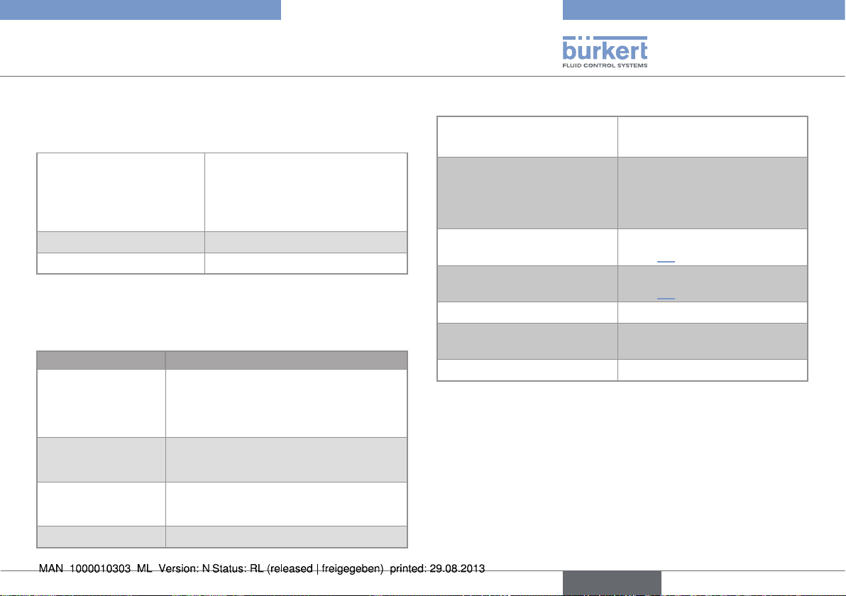
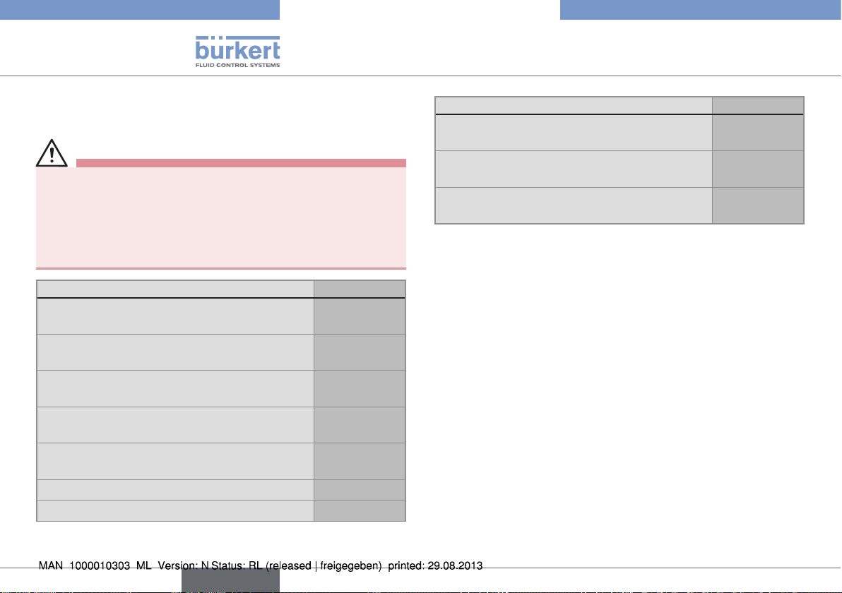
5.4. Available versions
Flow rate range Materials
Process
connection
Viscosity
> 1 mPa.s and
< 1000 mPa.s
Viscosity
< 1 mPa.s
Housing Rotors / axis Seal
G 1/8'' 0.5-50 l/h 5-50 l/h Aluminium Stainless steel FKM 5 bar
Stainless steel Stainless steel FFKM 55 bar
NPT 1/8'' 0.5-50 l/h 5-50 l/h Aluminium Stainless steel FKM 5 bar
Stainless steel Stainless steel FFKM 55 bar
Flow rate range Materials
Process
connection
Viscosity
> 5 mPa.s and
< 1000 mPa.s
Viscosity
< 5 mPa.s
Housing Rotors / axis Seal
G 1/4'' 2-100 l/h 12.5-100 l/h PPS PPS / Hastalloy C FFKM 5 bar
Stainless steel Stainless steel FFKM 55 bar
15-500 l/h 40-500 l/h PPS PPS / Hastalloy C FFKM 5 bar
Stainless steel Stainless steel FFKM 55 bar
NPT 1/4'' 2-100 l/h 12.5-100 l/h PPS PPS / Hastalloy C FFKM 5 bar
Stainless steel Stainless steel FFKM 55 bar
15-500 l/h 40-500 l/h PPS PPS / Hastalloy C FFKM 5 bar
Stainless steel Stainless steel FFKM 55 bar
Max.
pressure
Max.
pressure
Order code
1)
552818
552820
552819
552821
Order code
1)
432288
433864
430856
437518
448654
448656
448655
448657
English
9
Page 10

Type 8071
Description
Process
connection
Flow rate range Materials
Viscosity > 1000 mPa.s Housing Rotors / axis Seal
Max.
pressure
G 1/4'' 15-500 l/h Stainless steel Stainless steel FFKM 55 bar
NPT 1/4'' 15-500 l/h Stainless steel Stainless steel FFKM 55 bar
1)
High pressure versions available on request
2)
Other high viscosity versions available on request
Order code
1)
552426
553652
2)
10
English
Page 11
Type 8071
Technical data
6. TECHNICAL DATA
6.1. Conditions of use
Ambient temperature
• Aluminium or PPS housing
• Stainless steel housing
Air humidity < 85%, non condensated
Protection rating IP54 (NEMA 13)
6.2. General data
6.2.1. Mechanical data
Part Material
Housing • Aluminium
Rotors • PPS
Axis • Hastalloy C
Seal FKM or FFKM
• max. 80 °C
• max. 120 °C
• PPS
• Stainless steel 316F (1.4401)
• Stainless steel 316F (1.4401)
• Stainless steel 316F (1.4401)
6.2.2. General data
Process connection Internal thread G 1/8" or G 1/4",
NPT 1/8’’or NPT 1/4’’
Max. fluid pressure
• PPS or aluminium housing
• Stainless steel housing
Viscosity
Flow rate measuring range
Accuracy ≤ ± 1 % of the measured value
Repeatability ≤ ± 0,03 % of the measured
Max. size of particles 75 µm
• 5 bar
• 55 bar (550 bar on request)
Depends on the version (see
chap. 5.4)
Depends on the version (see
chap. 5.4)
value
English
11
Page 12
Type 8071
Technical data
6.2.3. Electrical data
Supply voltage 4,5- 24 V DC
Tansistor output
• Type of output
• Hall sensor max. intensity
• Recommended load
Reed switch output
• Type
• Max. switching voltage
• Max. switching current
• Max. operating current
• Number of cycles (typical)
Electrical connection 5-wire cable, 1m long
• Frequency on open collector,
NPN, max. 25 mA, 4,5 to
24 V DC
• 25 mA
• 1,8 Kohm Pull up at 24 VDC
• Frequency
• 30 VDC
• 0,5 A
• 0,5 A
6
• 500 x 10
cycles (at 10 VDC
and 10 mA)
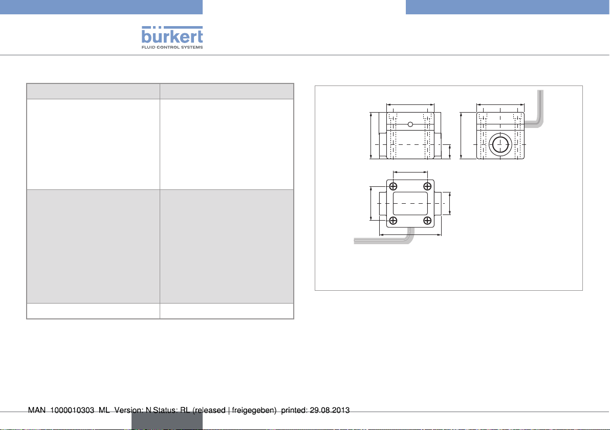
6.3. Dimensions
51/51/60*
48
A24
36,5
36,5
60/50/64*
cable 1000 mm
* Aluminium / Stainless steel / PPS housing
A: 17...18 mm depending on the housing material
Fig. 3: Dimensions of the device
51/51/60*
48
12
English
Page 13
Type 8071
Installation and Wiring
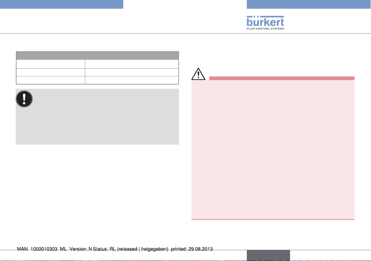
6.4. K factors (in pulse/l)
Flow rate range K factor (in pulse/l)
0,5- 50 l/h 1552
2- 100 l/h 1000
15- 500 l/h 400
If the device is combined with an instrument which does not
automatically convert the K factors, make the conversion
using one of the following formulae:
K factor in pulse/gallon US = K factor in pulse/l x 3,785 to
obtain flow rate in gallon US / time unit
K factor in pulse/gallon UK = K factor in pulse/l x 4,546 to
obtain flow rate in gallon UK / time unit.
7. INSTALLATION AND WIRING
7.1. Safety instructions
danger
Risk of injury due to high pressure in the installation.
• Stop the circulation of fluid, cut off the pressure and drain the
pipe before loosening the process connections.
Risk of injury due to electrical voltage.
• Shut down and isolate the electrical power source before
carrying out work on the system.
• Observe all applicable accident protection and safety regulations for electrical equipment.
Risk of injury due to the nature of the fluid.
• Respect the prevailing regulations on accident prevention and
safety relating to the use of aggressive fluids.
Risk of injury due to high fluid temperatures.
• Use safety gloves to handle the device.
• Stop the circulation of fluid and drain the pipe before loosening
the process connections.
• Keep all easily flammable material and fluid away from the
device.
English
13
Page 14

Type 8071
Installation and Wiring
Warning
Risk of injury due to non-conforming installation.
• The electrical and fluid installation can only be carried out by
qualified and skilled staff with the appropriate tools.
• Install the appropriate security devices (correctly dimensioned
fuse and/or circuit breaker).
Risk of injury due to unintentional switch on of power supply
or uncontrolled restarting of the installation.
• Take appropriate measures to avoid unintentional activation of
the installation.
• Guarantee a set or controlled restarting of the process subsequent to the installation of the device.
7.2. Installation instructions
note
Risk of damaging the device if it is subjected to mechanical
stress.
• Use flexible hoses.
note
The oval rotors may be damaged if particles with diameter > 75 µm go into the fitting.
• Install a strainer of 75 µm upstream and as close as possible to
the device.
→ Install a by-pass line on your installation to service the device
and the strainer without stopping the process (see Fig. 4).
filter
valve
8071
direction of flow
Fig. 4: Installation of a by-pass line
→ Install the device onto the pipe so that the shafts of the rotors
are in a horizontal plane.
Seal the external threads of the fitting with a product compatible with the materials from which the device housing
and the pipe are made.
→ Screw the device onto the pipe.
14
English
Page 15

Type 8071
Installation and Wiring
7.3. Wiring
danger
Risk of injury due to electrical voltage.
• Shut down and isolate the electrical power source before
carrying out work on the system.
• Observe all applicable accident protection and safety regulations for electrical equipment.
• Use a high quality electrical power supply (filtered and
regulated).
• Make sure the installation is equipotential.
Red wire
Black wire
White wire
Yellow wire
Green wire
Table 1: Connection wire assignment
Power supply (+)
Power supply (-)
NPN transistor output
Reed switch
Reed switch
7.3.1. Wiring the NPN transistor output and
the Reed switch output
L+ (4,5 - 24 V DC)
(red wire)
L- (black wire)
NPN transistor out-
put (white wire)
R=1,8 kW pull-up at 24 VDC
Fig. 5: Wiring of NPN transistor output and the Reed switch
output
IN
+-
IN = pulse input on remote transmitter
Remote transmitter
Fig. 6: Example for the connection of the NPN transistor output to
a remote transmitter
R
V DC
NPN
X
yellow wire
green wire
L+
L-
V DC
X
8071
English
15
Page 16

Type 8071
Commisioning
8. COMMISIONING
8.1. Safety instructions
Warning
Risk of injury due to nonconforming commissioning.
Non conforming commissioning may lead to injuries and damage
the device and its surroundings.
• Before commissioning, make sure that the staff in charge have
read and fully understood the contents of the manual.
• In particular, observe the safety recommendations and intended
use.
• The device / the installation must only be commissioned by
suitably trained staff.
Protect this device against electromagnetic interference,
ultraviolet rays and, when installed outdoors, the effects of
the climatic conditions.
The pipe must be full of liquid whitout air bubbles.
→ Drain air from the pipe by gradually filling the pipe with fluid.
→ Make sure the installation is tight.
9. MAINTENANCE AND TROUBLESHOOTING
9.1. Safety instructions
danger
Risk of injury due to high pressure in the installation.
• Stop the circulation of fluid, cut off the pressure and drain the
pipe before loosening the process connections.
Risk of injury due to electrical voltage.
• Shut down and isolate the electrical power source before
carrying out work on the system.
• Observe all applicable accident protection and safety regulations for electrical equipment.
Risk of injury due to the nature of the fluid.
• Respect the prevailing regulations on accident prevention and
safety relating to the use of aggressive fluids.
Risk of injury due to high fluid temperatures.
• Use safety gloves to handle the device.
• Stop the circulation of fluid and drain the pipe before loosening
the process connections.
• Keep all easily flammable material and fluid away from the
device.
16
English
Page 17

Type 8071
Maintenance and troubleshooting
Warning
Risk of injury due to non-conforming maintenance.
• Maintenance must only be carried out by qualified and skilled
staff with the appropriate tools.
• Guarantee a set or controlled restarting of the process, after a
power supply interruption.
9.2. Maintenance of the strainer
→ After the circulation of 200 liters of fluid, examine the strainer for
particles. If necessary clean the strainer with a product compatible with the materials from which it is made.
→ Regularly examine the strainer for good condition, in particular
when the flow rate decreases. If necessary clean the strainer
with a product compatible with the materials from which it is
made.
9.3. Maintenance of the device
→ Regularly examine the seal and the oval rotors for good
condition. Follow the instructions on chap. 9.4 et 9.5.
Clean the device with a cloth slightly dampened with water or a
cleaning liquid compatible with the materials the device is made of.
Your Bürkert supplier is at your disposal for any further information.
9.4. Dismantle the device
grooves
1
2
3
4
5
Fig. 7: Exploded view of the device
→ Unscrew the 4 screws (mark 5 Fig. 7) and remove the cover
including the electronic module (mark 4 Fig. 7).
→ Remove the seal (mark 3 Fig. 7).
→ Examine the seal for good condition. If not, replace it by a new
one (see chap. "10. Spare parts and accessories").
→ Remove the rotors (mark 2 Fig. 7).
→ Examine the rotors for good condition. If necessary, clean or
replace them (see chap. 10).
English
17
Page 18

9.5. Assemble the device
Type 8071
Maintenance and troubleshooting
Put the magnetized rotor on the same side as the groove
(see Fig. 8 and table below).
→ Put the rotors inside the housing, at 90° (see Fig. 8).
groove
Magnetized oval rotor
Neutral oval rotor (without magnet)
Fig. 8: Position of the oval rotors
Flow rate range Magnetized oval rotor
0.5-50 l/h hole of the magnet seat is visible (set towards
the cover)
• 0.5-50 l/h
• 2-100 l/h
• 15-500 l/h
hole of the magnet seat is not visible (set
towards the bottom of the housing)
→ Set the radius of curvature present on the periphery of the oval
rotors towards the bottom of the rotor housing (see Fig. 9).
A A
right angle
round-off
A-A
Fig. 9: Cross-section of an oval rotor
→ Make sure that the magnet is in place by using a detector.
→ Make sure that the rotors freely turn by turning them slowly with
the finger.
→ Put the seal (mark 3 Fig. 7) in its groove.
→ Put the cover (mark 4 Fig. 7) on the housing, aligning the groove
on the cover with the one of the housing.
→ Tighten the 4 screws (mark 5 Fig. 7), carefully to avoid damages
to the housing, and in an alternating pattern at the following
torque:
- 1 Nm for a PPS housing
- 2 Nm for an aluminium housing
- 9 Nm for a stainless steel housing
18
English
Page 19

Type 8071
Maintenance and troubleshooting
9.6. If a problem occurs
Problem Cause Solution
Fluid does not
flow through the
device any more
Obturated device
Obturated strainer (if present)
Rotors damaged
→ Remove and clean the oval rotors (see chap. "9.4. Dismantle the device" and
"9.5. Assemble the device").
→ Add a strainer of 75 µm upstream of the device.
→ Clean the strainer.
→ Replace the rotors (see chap. "10. Spare parts and accessories", "9.4. Dis-
mantle the device" and "9.5. Assemble the device").
Reduced flow
rate through the
device
Incoherent
measurement
No frequency
output
Strainer (if present) partially obturated
Fluid too viscous Use rotors for fluids with a viscosity > 1000 mPa.s.
Flow rate range not adapted
Air within the pipe
Friction due to an incorrect assembly
of the device
Incorrect wiring of the outputs
Rotors incorrectly mounted
Magnet damaged
Hall sensor or Reed switch defective
→ Clean the strainer.
→ Verify specifications, adjust the device or the flow rate (see chap. "6.2.2.
General data").
→ Slowly drain air from the pipe.
→ Verify the assembly of the rotors in the fitting (see chap. "9.4. Dismantle the
device" and chap. "9.5. Assemble the device").
→ Make sure that the device has been wired correctly (see chap. "7.3. Wiring").
→ Dismantle the device and modify the position of the rotors (see "9.4. Dismantle
the device" and "9.5. Assemble the device").
→ Replace the rotors (see chap. "10. Spare parts and accessories", "9.4. Dis-
mantle the device" and "9.5. Assemble the device").
→ Replace the cover with electronic module (see chap. "10. Spare parts and
accessories", 9.4 and 9.5).
English
19
Page 20
Type 8071
Spare parts and accessories
10. SPARE PARTS AND
ACCESSORIES
caution
Risk of injury and damage caused by the use of unsuitable
parts.
Incorrect accessories and unsuitable spare parts may cause
injuries and damage the device and the surrounding area.
• Use only original accessories and original spare parts from
Bürkert.
Spare part Order code
Set of 2 oval rotors in stainless steel, flow rate
range of 0.5-50 l/h
Set of 2 oval rotors in stainless steel, flow rate
range of 2-100 l/h
Set of 2 oval rotors in stainless steel, flow rate
range of 15-500 l/h
Set of 2 oval rotors in PPS, flow rate range of
2-100 l/h
Set of 2 oval rotors in PPS, flow rate range of
15-500 l/h
FKM seal 550923
FFKM seal 550959
560180
550919
550920
550921
550922
Spare part Order code
Cover in stainless steel with electronic module
including Hall effect sensor and Reed switch
Cover in PPS with electronic module including
Hall effect sensor and Reed switch
Cover in aluminium with electronic module
including Hall effect sensor and Reed switch
553653
553654
on request
20
English
Page 21
Type 8071
Packaging, Transport
11. PACKAGING, TRANSPORT
note
Damage due to transport
Transport may damage an insufficiently protected device.
• Transport the device in shock-resistant packaging and away
from humidity and dirt.
• Do not expose the device to temperatures that may exceed the
admissible storage temperature range.
• Protect the electrical interfaces using protective plugs.
12. STORAGE
note
Poor storage can damage the device.
• Store the device in a dry place away from dust.
• Storage temperature: -10...+60 °C.
13. DISPOSAL OF THE DEVICE
→
Dispose of the device and its packaging in an environmentallyfriendly way.
note
Damage to the environment caused by products contaminated by fluids.
• Keep to the existing provisions on the subject of waste disposal
and environmental protection.
note
Comply with the national and/or local regulations which
concern the area of waste disposal.
English
21
Page 22

Type 8071
22
English
Page 23

Type 8071
English
23
Page 24

Type 8071
24
English
Page 25

Typ 8071
Typ 8071
1. DIE BEDIENUNGSANLEITUNG ..............................................................4
1.1. Darstellungsmittel .............................................................................4
1.2. Begriffsdefinition "Gerät" ............................................................... 4
2. BESTIMMUNGSGEMÄSSE VERWENDUNG .....................................5
3. GRUNDLEGENDE SICHERHEITSHINWEISE ................................... 5
4. ALLGEMEINE HINWEISE ............................................................................ 7
4.1. Kontaktadressen ................................................................................ 7
4.2. Gewährleistung ................................................................................... 7
4.3. Informationen im Internet .............................................................. 7
5. BESCHREIBUNG ............................................................................................ 7
5.1. Vorgesehener Einsatzbereich ..................................................... 7
5.2. Allgemeine Beschreibung ............................................................. 7
5.3. Beschreibung des Typenschilds ................................................ 8
5.4. Verfügbare Versionen ...................................................................... 9
6. TECHNISCHE DATEN ............................................................................... 11
6.1. Betriebsbedingungen ................................................................... 11
6.2. Allgemeine technische Daten .................................................. 11
6.3. Abmessungen ................................................................................... 12
6.4. K-Faktoren (in Pulse/Liter) ........................................................ 13
7. INSTALLATION UND VERKABELUNG .............................................. 13
7.1. Sicherheitshinweise ...................................................................... 13
7.2. Empfehlungen für die Installation .......................................... 14
7.3. Verkabelung ....................................................................................... 15
8. INBETRIEBNAHME ..................................................................................... 16
8.1. Sicherheitshinweise ...................................................................... 16
9. WARTUNG, PROBLEMLÖSUNG .......................................................... 16
9.1. Sicherheitshinweise ...................................................................... 16
9.2. Wartung des Filters ........................................................................ 17
9.3. Wartung des Gerätes .................................................................... 17
9.4. Ausbau des Gerätes ...................................................................... 17
9.5. Wiederaufbau des Gerätes ........................................................ 18
9.6. Problemlösung ................................................................................. 19
10. ERSATZTEILE, ZUBEHÖR .................................................................... 20
11. VERPACKUNG, TRANSPORT .............................................................21
12. LAGERUNG .................................................................................................. 21
13. ENTSORGUNG DES GERÄTES ......................................................... 21
deutsch
Page 26

Typ 8071
Die Bedienungsanleitung
1. DIE BEDIENUNGSANLEITUNG
Die Bedienungsanleitung beschreibt den gesamten Lebenszyklus
des Gerätes. Bewahren Sie diese Anleitung so auf, dass sie für jeden
Benutzer zugänglich ist und jedem neuen Eigentümer des Gerätes
wieder zur Verfügung steht.
Diese Bedienungsanleitung enthält wichtige Informationen
zur Sicherheit!
Das Nichtbeachten dieser Hinweise kann zu gefährlichen Situationen führen.
• Diese Bedienungsanleitung muss gelesen und verstanden
werden.
1.1. Darstellungsmittel
Gefahr!
Warnt vor einer unmittelbaren Gefahr!
• Bei Nichteinhaltung sind Tod oder schwere Verletzungen die
Folge.
WarnunG!
Warnt vor einer möglicherweise gefährlichen Situation!
• Bei Nichteinhaltung drohen schwere Verletzungen oder Tod.
VOrSIChT!
Warnt vor einer möglichen Gefährdung!
• Nichtbeachtung kann mittelschwere oder leichte Verletzungen
zur Folge haben.
hInWeIS!
Warnt vor Sachschäden!
• Bei Nichtbeachtung kann das Gerät oder die Anlage beschädigt
werden.
bezeichnet wichtige Zusatzinformationen, Tipps und
Empfehlungen.
verweist auf Informationen in dieser Bedienungsanleitung
oder in anderen Dokumentationen.
→ markiert einen Arbeitsschritt, den Sie ausführen müssen.
1.2. Begriffsdefinition "Gerät"
Der in dieser Anleitung verwendete Begriff "Gerät" steht immer für
das Durchfluss-Messgerät Typ 8071.
4
deutsch
Page 27

Typ 8071
Bestimmungsgemässe Verwendung
2. BESTIMMUNGSGEMÄSSE
VERWENDUNG
Bei nicht bestimmungsgemäßem Einsatz des Gerätes können
Gefahren für Personen, Anlagen in der Umgebung und die
Umwelt entstehen.
• Das Gerät ist zur Durchflussmessung von Flüssigkeiten, insbesondere viskosen Flüssigkeiten bestimmt.
• Schützen Sie das Gerät vor elektromagnetischen Störungen, U.V.-Bestrahlung und bei Außenanwendung vor
Witterungseinflüssen.
• Für den Einsatz sind die in den Vertragsdokumenten und der
Bedienungsanleitung spezifizierten zulässigen Daten, Betriebs-
und Einsatzbedingungen zu beachten.
• Zum sicheren und problemlosen Einsatz des Gerätes müssen
Transport, Lagerung und Installation ordnungsgemäß erfolgen,
außerdem müssen Betrieb und Wartung sorgfältig durchgeführt
werden.
• Achten Sie immer darauf, dieses Gerät auf ordnungsgemäße
Weise zu verwenden.
→ Beachten Sie bei der Ausfuhr des Gerätes gegebenenfalls bes-
tehende Beschränkungen.
3. GRUNDLEGENDE SICHERHEITSHINWEISE
Diese Sicherheitshinweise berücksichtigen keine
• Zufälligkeiten und Ereignisse, die bei Montage, Betrieb und Wartung
der Geräte auftreten können.
• Ortsbezogenen Sicherheitsbestimmungen, für deren Einhaltung,
auch in Bezug auf das Installations- und Wartungspersonal, der
Betreiber verantwortlich ist.
Gefahr durch hohen Druck in der Anlage!
Gefahr durch elektrische Spannung!
Gefahr durch hohe Flüssigkeitstemperaturen!
Gefahr aufgrund der Art der Flüssigkeit!
Allgemeine Gefahrensituationen.
Zum Schutz vor Verletzungen ist zu beachten:
• Die Anlage nicht unbeabsichtigt betätigen.
• Installations- und Instandhaltungsarbeiten dürfen nur von autorisiertem Fachpersonal mit geeignetem Werkzeug ausgeführt
werden.
deutsch
5
Page 28

Allgemeine Gefahrensituationen.
Zum Schutz vor Verletzungen ist zu beachten:
• Nach einer Unterbrechung der elektrischen Versorgung ist ein
definierter oder kontrollierter Wiederanlauf des Prozesses zu
gewährleisten.
• Betreiben Sie das Gerät nur in einwandfreiem Zustand und
unter Beachtung der Bedienungsanleitung.
• Bei der Einsatzplanung und dem Betrieb des Fittings die allgemeinen Regeln der Technik einhalten.
• Das Gerät nicht in einer explosionsfähigen Atmosphäre verwenden.
• Das Gerät nicht in einer Umgebung verwenden, die mit den Materialien, aus denen es besteht, inkompatibel ist.
• Keine Flüssigkeit verwenden, die sich nicht mit den Werkstoffen
verträgt, aus denen das Gerät besteht.
• Das Gerät nicht für die Durchflussmessung von Gas einsetzen.
• Belasten Sie das Gerät nicht mechanisch (z. B. durch Ablage von
Gegenständen oder als Trittstufe).
• Nehmen Sie keine äußerlichen Veränderungen an den Gehäusen
vor. Lackieren Sie keinen Teil des Gerätes.
Typ 8071
Grundlegende Sicherheitshinweise
hInWeIS!
Das Gerät kann durch das Medium beschädigt werden.
• Kontrollieren Sie systematisch die chemische Verträglichkeit der
Werkstoffe, aus denen das Gerät besteht, und der Flüssigkeiten, die mit diesem in Berührung kommen können (zum Beispiel:
Alkohole, starke oder konzentrierte Säuren, Aldehyde, Basen,
Ester, aliphatische Verbindungen, Ketone, aromatische oder
halogenierte Kohlenwasserstoffe, Oxidations- und chlorhaltige
Mittel).
hInWeIS!
Elektrostatisch gefährdete Bauelemente / Baugruppen!
Das Gerät enthält elektronische Bauelemente, die gegen elektrostatische Entladung (ESD) empfindlich reagieren. Berührung mit
elektrostatisch aufgeladenen Personen oder Gegenständen
gefährdet diese Bauelemente. Im schlimmsten Fall werden sie
sofort zerstört oder fallen nach der Inbetriebnahme aus.
• Beachten Sie die Anforderungen nach EN 61340 -5-1 und 5-2,
um die Möglichkeit eines Schadens durch schlagartige elektrostatische Entladung zu minimieren bzw. zu vermeiden!
• Achten Sie ebenso darauf, dass Sie elektronische Bauelemente
nicht bei anliegender Versorgungsspannung berühren!
6
deutsch
Page 29

Typ 8071
Allgemeine Hinweise
4. ALLGEMEINE HINWEISE
4.1. Kontaktadressen
Bürkert SAS
Rue du Giessen
BP 21
F-67220 TRIEMBACH-AU-VAL
oder wenden Sie sich an Ihren lokal zuständigen Vertriebsmitarbeiter
von Bürkert.
Die internationalen Kontaktadressen finden Sie im Internet unter:
www.burkert.com
4.2. Gewährleistung
Voraussetzung für die Gewährleistung ist der bestimmungsgemäße
Gebrauch des Gerätes unter Beachtung der im vorliegenden Handbuch spezifizierten Einsatzbedingungen.
4.3. Informationen im Internet
Bedienungsanleitungen und Datenblätter zum Typ 8071 finden Sie im
Internet unter: www.buerkert.de
5. BESCHREIBUNG
5.1. Vorgesehener Einsatzbereich
Das Gerät ermöglicht aufgrund seiner Ovalräder die Durchflussmessung viskoser Flüssigkeiten. Es muss in Verbindung mit einem
abgesetzten Gerät (z.B. Transmitter 8025 Universal oder Dosiergerät
8025 Batch) zur Erfassung/Konvertierung der durch die Rotation der
Ovalräder erzeugten Impulsfrequenz verwendet werden.
5.2. Allgemeine Beschreibung
5.2.1. Aufbau
Das Gerät besteht aus einem Fitting mit integrierten Ovalrädern und
einem Deckel mit Elektronikmodul, das ein Halleffekt-Sensor und ein
Reed-Schalter enthält.
Die Ovalräder des Fittings enthalten Magnete.
Alle Ausführungen des Sensors weisen einen NPN Transistorausgang
und einen Reed-Schalter auf.
Der elektrische Anschluss erfolgt über einen 1m-langen 5-adrigen
Kabel.
5.2.2. Messprinzip
Die durch die Rohrleitung fließende Flüssigkeit bewirkt das Drehen
der Ovalräder, die Magnete enthalten (siehe Bild 1). Die Bewegung
der Magnete erzeugt eine Magnetfeldänderung. Der Sensor misst die
Magnetfeldänderung und konvertiert dieses Signal in eine Frequenz.
Diese Frequenz ist dann an dem NPN-Transistorausgang und dem
deutsch
7
Page 30

Reed-Schalter-Ausgang verfügbar.
Bild 1: Funktionsweise/Bewegung der Ovalräder
Das abgesetzte Instrument konvertiert die Frequenz mit dem geeigneten K-Faktor in einen Durchflusswert.
5.3. Beschreibung des Typenschilds
Type 8071 Flow Sensor
1
Model
2
Flow Range
3
Max Pressure
4
Max Temp
Serial No
5
Bild 2: Typenschild des Gerätes
1. Bestell-Nummer des Gerätes
2. Messbereich des Durchflusses
3. Max. Druck
4. Höchsttemperatur
5. Seriennummer
433864N
2-100LPH
1000kPa/55Bar
120°C
D34128
Typ 8071
Beschreibung
8
deutsch
Page 31

Typ 8071
Beschreibung
5.4. Verfügbare Versionen
Durchfluss-Messbereich Werkstoffe
ProzessAnschluss
Viskosität
> 1 mPa.s und
< 1000 mPa.s
Viskosität
< 1 mPa.s
Gehäuse Räder / Achse Dichtung
G 1/8'' 0.5-50 l/h 5-50 l/h Aluminium Edelstahl FKM 5 bar
Edelstahl Edelstahl FFKM 55 bar
NPT 1/8'' 0.5-50 l/h 5-50 l/h Aluminium Edelstahl FKM 5 bar
Edelstahl Edelstahl FFKM 55 bar
Durchfluss-Messbereich Werkstoffe
ProzessAnschluss
Viskosität
> 5 mPa.s und
< 1000 mPa.s
Viskosität
< 5 mPa.s
Gehäuse Räder / Achse Dichtung
G 1/4'' 2-100 l/h 12.5-100 l/h PPS PPS / Hastalloy C FFKM 5 bar
Edelstahl Edelstahl FFKM 55 bar
15-500 l/h 40-500 l/h PPS PPS / Hastalloy C FFKM 5 bar
Edelstahl Edelstahl FFKM 55 bar
NPT 1/4'' 2-100 l/h 12.5-100 l/h PPS PPS / Hastalloy C FFKM 5 bar
Edelstahl Edelstahl FFKM 55 bar
15-500 l/h 40-500 l/h PPS PPS / Hastalloy C FFKM 5 bar
Edelstahl Edelstahl FFKM 55 bar
max.
Druck
max.
Druck
Bestellnummer
1)
Bestellnummer
1)
552818
552820
552819
552821
432288
433864
430856
437518
448654
448656
448655
448657
deutsch
9
Page 32

Typ 8071
Beschreibung
ProzessAnschluss
Durchfluss-Messbereich Werkstoffe
Viskosität > 1000 mPa.s Gehäuse Räder / Achse Dichtung
max.
Druck
G 1/4'' 15-500 l/h Edelstahl Edelstahl FFKM 55 bar
NPT 1/4'' 15-500 l/h Edelstahl Edelstahl FFKM 55 bar
1)
Hochdruckversion auf Anfrage erhältlich
2)
Weitere Hochviskosität-Versionen auf Anfrage erhältlich
1)
BestellNummer
552426
553652
2)
10
deutsch
Page 33

Typ 8071
Technische Daten
6. TECHNISCHE DATEN
6.1. Betriebsbedingungen
Umgebungs-Temperatur
• Gehäuse aus Aluminium
oder PPS
• Gehäuse aus Edelstahl
Luftfeuchtigkeit < 85%, nicht kondensierend
Schutzart IP54 (NEMA 13)
6.2. Allgemeine technische Daten
6.2.1. Mechanische Daten
Teil Werkstoff
Gehäuse • Aluminium
Räder • PPS
Achse • Hastalloy C
Dichtung FKM oder FFKM
• max. 80 °C
• max. 120 °C
• PPS
• Edelstahl 316F (1.4401)
• Edelstahl 316F (1.4401)
• Edelstahl 316F (1.4401)
6.2.2. Allgemeine Daten
Prozess-Anschluss Innengewinde, G 1/8", G 1/4",
NPT 1/8’’oder NPT 1/4’’
Max. Flüssigkeitsdruck
• Gehäuse aus PPS oder
Aluminium
• Gehäuse aus Edelstahl
Viskosität
Messbereich des Durchflusses
Genauigkeit ≤ ± 1 % des Messwertes
Wiederholbarkeit ≤ ± 0,03 % des Messwertes
Max. Partikel-Größe 75 µm
• 5 bar
• 55 bar (550 bar auf Anfrage)
je nach Ausführung (siehe
Kap. 5.4)
je nach Ausführung (siehe
Kap. 5.4)
deutsch
11
Page 34

Typ 8071
Technische Daten
6.2.3. Elektrische Daten
Betriebsspannung 4,5 - 24 V DC
Transistor-Ausgang
• Ausgangs-Typ
• Max. Intensität des
Hallsensors
• Empfohlene Last
Reed-Schalter-Ausgang
• Ty p
• Schaltspannung
• Schaltstrom
• Max. Arbeitsstrom
• Anzahl Zyklen (typisch))
Elektrischer Anschluss 5-adriges Kabel, 1m lang
• Frequenz über Open Kollektor, NPN, max. 25 mA, 4,5
bis 24 V DC
• 25 mA
• 1,8 Kohm Pull up bei 24 VDC
• Frequenz
• 30 VDC
• 0,5 A
• 0,5 A
6
• 500 x 10
Zyklen (bei
10 VDC und 10 mA)
6.3. Abmessungen
51/51/60*
48
A24
36,5
36,5
60/50/64*
1000 mm-Kabel
* Gehäuse aus Aluminium / Edelstahl / PPS
A: 17...18 mm je nach Werkstoff des Gehäuses
Bild 3: Abmessungen des Gerätes
51/51/60*
48
12
deutsch
Page 35

Typ 8071
Installation und Verkabelung
6.4. K-Faktoren (in Pulse/Liter)
Durchfluss-Messbereich K-Faktor (in Pulse/Liter)
0,5- 50 l/h 1552
2- 100 l/h 1000
15- 500 l/h 400
Wenn das Gerät mit einem Instrument verbunden ist,
das die K-Faktoren nicht automatisch umrechnet, die
Umrechnung mit einer der folgenden Formeln vornehmen:
K-Faktor in Pulse/US-Gallone = K-Faktor in Pulse/Liter x
3,785 zur Umrechnung des Durchflusses in US-Gallonen/
Zeiteinheit
K-Faktor in Pulse/UK-Gallone = K-Faktor in Pulse/Liter x
4,546 zur Umrechnung des Durchflusses in UK-Gallonen/
Zeiteinheit
7. INSTALLATION UND
VERKABELUNG
7.1. Sicherheitshinweise
Gefahr!
Verletzungsgefahr durch hohen Druck in der Anlage!
• Vor dem Lösen der Prozessanschlüsse die Anlage druckfrei
schalten und die Flüssigkeitszirkulation stoppen.
Verletzungsgefahr durch Stromschlag!
• Schalten Sie vor Beginn der Arbeiten in jedem Fall die Spannung ab, und sichern Sie diese vor Wiedereinschalten!
• Beachten Sie geltende Unfallverhütungs- und Sicherheitsbestimmungen für elektrische Geräte!
Verletzungsgefahr aufgrund der Art der Flüssigkeit!
• Beachten Sie die Regeln, die auf dem Gebiet der Unfallverhütung
und der Sicherheit in Kraft sind und die sich auf die Verwendung
gefährlicher Produkte beziehen.
Verletzungsgefahr durch hohe Flüssigkeitstemperaturen!
• Das Gerät nur mit Schutzhandschuhen anfassen.
• Vor dem Lösen der Prozessanschlüsse die Flüssigkeitszirkulation stoppen und die Rohrleitung leeren.
• Leicht brennbare Materialien und Medien vom Gerät fernhalten.
deutsch
13
Page 36

Typ 8071
Installation und Verkabelung
WarnunG!
Verletzungsgefahr bei unsachgemäßer Installation!
• Fluidische und elektrische Installationen dürfen nur durch autorisiertes Fachpersonal und mit geeignetem Werkzeug durchgeführt werden!
• Verwenden Sie unbedingt geeignete Sicherheitsvorrichtungen (ordnungsgemäß dimensionierte Sicherungen und/oder
Sicherungsautomat).
Verletzungsgefahr durch ungewolltes Einschalten der Anlage
und unkontrollierten Wiederanlauf!
• Anlage vor unbeabsichtigtem Betätigen sichern.
• Nach der Instalaltion einen kontrollierten Wiederanlauf
gewährleisten.
7.2. Empfehlungen für die Installation
hInWeIS!
Gefahr der Beschädigung des Gerätes, wenn dieser mechanisch belastet wird.
• Schläuche verwenden.
hInWeIS!
Gefahr der Beschädigung der Ovalräder, wenn Partikel mit
einem Durchmesser > 75 µm in den Sensor gelangen.
• Einen 75-µm-Filter so dicht wie möglich vor dem Gerät
installieren.
→ Um die Wartung des Gerätes und des Filters durchführen zu
können, ohne den Prozess zu unterbrechen, einen Bypass in
Ihrer Anlage vorsehen (siehe Bild 4).
Filter
Ventil
8071
Flüssigkeits-Richtung
Bild 4: Installation des Bypass
→ Das Gerät so in der Rohrleitung installieren, dass die Achsen der
Räder in einer Horizontalebene liegen.
Die Außengewinde mit einem Produkt abdichten, das
sich mit den Werkstoffen des Fittings und der Rohrleitung
verträgt.
→ Das Gerät an die Rohrleitung schrauben.
14
deutsch
Page 37

Typ 8071
Installation und Verkabelung
7.3. Verkabelung
Gefahr!
Verletzungsgefahr durch Stromschlag!
• Schalten Sie vor Beginn der Arbeiten in jedem Fall die Spannung ab, und sichern Sie diese vor Wiedereinschalten!
• Beachten Sie geltende Unfallverhütungs- und Sicherheitsbestimmungen für elektrische Geräte!
• Eine hochwertige (gefilterte und geregelte) Stromversorgung verwenden.
• Den Potentialausgleich der Installation gewährleisten.
Rote Ader
Schwarze Ader
Weiße Ader
Gelbe Ader
Grüne Ader
Tab. 1: Belegung des Anschluss-Kabels
Stromversorgung (+)
Stromversorgung (-)
NPN-Transistorausgang
Reed-Schalter
Reed-Schalter
7.3.1. Anschluss des NPNTransistorausgangs und des
Reed-Schalterausgangs
L+ (4,5 - 24 V DC)
(rote Ader)
L- (schwarze Ader)
NPN-Transistoraus-
gang (weiße Ader)
1,8 WKohm Pull up bei 24 V DC
Bild 5: Anschluss des NPN-Transistorausgangs und des
Reed-Schalterausgangs
IN
+-
IN = Pulseingang des angeschlossenen Transmitters
angeschlossener
Transmitter
R
V DC
NPN
X
gelbe Ader
grüne
Ader
L+
L-
V DC
X
8071
Bild 6: Beispiel für den Anschluss des NPN-Transistorausgangs
an ein abgesetzter Transmitter
deutsch
15
Page 38

Typ 8071
Inbetriebnahme
8. INBETRIEBNAHME
8.1. Sicherheitshinweise
WarnunG!
Verletzungsgefahr bei unsachgemäßer Inbetriebnahme!
Nicht sachgemäße Inbetriebnahme kann zu Verletzungen sowie
Schäden am Gerät und seiner Umgebung führen.
• Vor der Inbetriebnahme muss gewährleistet sein, dass der Inhalt
der Bedienungsanleitung dem Bedienungspersonal bekannt ist
und vollständig verstanden wurde.
• Besonders zu beachten sind die Sicherheitshinweise und die
bestimmungsgemäße Verwendung.
• Das Gerät/die Anlage darf nur durch ausreichend geschultes
Personal in Betrieb genommen werden.
Schützen Sie das Gerät vor elektromagnetischen
Störungen, U.V.-Bestrahlung und bei Außenanwendung vor
Witterungseinflüssen.
Die Rohrleitung muss gefüllt und luftblasenfrei sein.
→ Die Luft aus der Rohrleitung entfernen, indem das Rohr nach
und nach mit Flüssigkeit gefüllt wird.
→ Die Dichtheit der Anlage kontrollieren.
9. WARTUNG, PROBLEMLÖSUNG
9.1. Sicherheitshinweise
Gefahr!
Verletzungsgefahr durch hohen Druck in der Anlage!
• Vor dem Lösen der Prozessanschlüsse die Anlage druckfrei
schalten und die Flüssigkeitszirkulation stoppen.
Verletzungsgefahr durch Stromschlag!
• Schalten Sie vor Beginn der Arbeiten in jedem Fall die Spannung ab, und sichern Sie diese vor Wiedereinschalten!
• Beachten Sie geltende Unfallverhütungs- und Sicherheitsbestimmungen für elektrische Geräte!
Verletzungsgefahr aufgrund der Art der Flüssigkeit!
• Beachten Sie die Regeln, die auf dem Gebiet der Unfallverhütung
und der Sicherheit in Kraft sind und die sich auf die Verwendung
gefährlicher Produkte beziehen.
Verletzungsgefahr durch hohe Flüssigkeitstemperaturen!
• Das Gerät nur mit Schutzhandschuhen anfassen.
• Vor dem Lösen der Prozessanschlüsse die Flüssigkeitszirkulation stoppen und die Rohrleitung leeren.
• Leicht brennbare Materialien und Medien vom Gerät fernhalten.
16
deutsch
Page 39

Typ 8071
Wartung, Problemlösung
WarnunG!
Gefahr durch unsachgemäße Wartungsarbeiten!
• Wartungsarbeiten dürfen nur durch autorisiertes Fachpersonal
und mit geeignetem Werkzeug durchgeführt werden!
• Nach einer Unterbrechung der elektrischen Versorgung ist ein
definierter oder kontrollierter Wiederanlauf des Prozesses zu
gewährleisten.
9.2. Wartung des Filters
→ Nach Durchlauf der ersten 200 Liter Flüssigkeit kontrollieren, ob
der Filter Späne oder Ablagerungen enthält. Ihn erforderlichenfalls mit einem Produkt reinigen, das sich mit den Materialien
verträgt, aus denen er besteht.
→ Den Filterzustand regelmäßig überprüfen, insbesondere wenn
der Durchfluss der Flüssigkeit geringer wird. Ihn erforderlichenfalls mit einem Produkt reinigen, das sich mit den Materialien
verträgt, aus denen er besteht.
9.3. Wartung des Gerätes
→ Regelmäßig den Zustand der Dichtung und der Ovalräder
des Gerätes überprüfen. Vorgehen wie unter Kap. 9.4 und 9.5
beschrieben.
Das Gerät nur mit einem Tuch oder Lappen reinigen, der leicht mit
Wasser oder mit einem Mittel befeuchtet ist, das sich mit den Werkstoffen des Gerätes verträgt.
Wenn Sie ergänzende Informationen wünschen, steht Ihnen Ihr Lieferant Bürkert voll und ganz zur Verfügung.
9.4. Ausbau des Gerätes
Rillen
1
2
3
4
5
Bild 7: Explosionszeichnung des Gerätes
→ Die 4 Schrauben (Marke 5 Bild 7) lösen und den Deckel mit
Elektronikmodul (Marke 4 Bild 7) abnehmen.
→ Die Dichtung (Marke 3 Bild 7) entfernen.
→ Den Zustand der Dichtung überprüfen. Wenn sie beschädigt ist,
ersetzen (siehe Kap. "10. Ersatzteile, Zubehör").
→ Die Räder herausnehmen (Marke 2 Bild 7).
→ Den ordnungsgemäßen Zustand der Räder kontrollieren. Sie
reinigen bzw. ersetzen, falls erforderlich (siehe Kap. 10).
deutsch
17
Page 40

9.5. Wiederaufbau des Gerätes
Typ 8071
Wartung, Problemlösung
Das mit dem Magnet versehene Rad muss wieder auf der
Seite mit der Rille eingesetzt werden (siehe Bild 8 und die
folgende Tabelle).
→ Die um 90° gegeneinander versetzten Räder wieder in das
Gehäuse einsetzen (siehe Bild 8).
Rille
Ovalrad mit Magnet
neutrales Ovalrad (ohne Magnet)
Bild 8: Positionierung der Ovalräde
DurchflussMessbereich
0.5-50 l/h Die Öffnung der Magnetaufnahme ist sichtbar
• 0.5-50 l/h
• 2-100 l/h
• 15-500 l/h
Ovalrad mit Magnet
(zeigt zum Deckel)
Die Öffnung der Magnetaufnahme ist nicht
sichtbar (zeigt zum Gehäuseboden)
→ Krümmungsradius am Umfang der Ovalräder gegen Gehäuse-
boden orientieren (siehe Bild 9).
A A
rechter Winkel
Abrundung
A-A
Bild 9: Schnittzeichnung eines Ovalrads
→ Das Vorhandensein des Magneten mit einem Detektor
überprüfen.
→ Überprüfen, ob die Räder sich frei drehen, indem sie vorsichtig
mit dem Finger gedreht werden.
→ Die Dichtung (Marke 3 Bild 7) wieder einsetzen.
→ Den Deckel (Marke 4 Bild 7) wieder aufsetzen, dabei die Rille
des Deckels auf diejenige des Gehäuses ausrichten.
→ Die 4 Schrauben (Marke 5 Bild 7) vorsichtig, um das Gehäuse
nicht zu beschädigen, mit folgendem Anzugsdrehmoment über
Kreuz festziehen:
- 1 Nm bei einem Gehäuse aus PPS
- 2 Nm bei einem Gehäuse aus Aluminium
- 9 Nm bei einem Gehäuse aus Edelstahl
18
deutsch
Page 41

Typ 8071
Wartung, Problemlösung
9.6. Problemlösung
Problem Ursache Lösung
Die Flüssigkeit
läuft nicht mehr
durch das Gerät
ab
Gerät verstopft
Filter verstopft (falls vorhanden)
Räder beschädigt
→ Die Räder demontieren und reinigen (siehe Kap. "9.4. Ausbau des Gerätes"
und "9.5. Wiederaufbau des Gerätes").
→ 75-µm-Filter vor dem Gerät einbauen.
→ Den Filter reinigen.
→ Die Räder auswechseln (siehe Kap. "10. Ersatzteile, Zubehör", "9.4. Ausbau
des Gerätes" und "9.5. Wiederaufbau des Gerätes").
Durchfluss
durch das Gerät
verringert
Widersprüchliche
Messwerte
Kein Signal am
Frequenzausgang
Filter (falls vorhanden) teilweise
verstopft
Flüssigkeit zu viskos Räder für Viskositäten höher als 1000 mPa.s verwenden.
Ungeeignetes
Durchfluss-Messbereich
Luft in der Rohrleitung
Reibung aufgrund fehlerhafter Wiedermontage des Gerätes
Falsche Verkabelung der Ausgänge
Räder falsch herum montiert
Magnet defekt
Hallsensor oder Reed-Schalter defekt
→ Den Filter reinigen.
→ Technische Daten überprüfen, Gerät oder Durchfluss anpassen (siehe
Kap. "6.2.2. Allgemeine Daten").
→ Langsam die Luft aus der Rohrleitung ablassen.
→ Die Montage der Räder im Gerät überprüfen (siehe Kap. "9.4. Ausbau des
Gerätes" und Kap. "9.5. Wiederaufbau des Gerätes").
→ Die Verkabelung überprüfen (siehe Kap. "7.3. Verkabelung").
→ Das Gerät demontieren und die Position der Räder ändern (siehe "9.4.
Ausbau des Gerätes" und "9.5. Wiederaufbau des Gerätes").
→ Die Räder auswechseln (siehe Kap. "10. Ersatzteile, Zubehör", "9.4. Ausbau
des Gerätes" und "9.5. Wiederaufbau des Gerätes").
→ Den Deckel mit Elektronikmodul ersetzen (siehe Kap. "10. Ersatzteile,
Zubehör", 9.4 und 9.5).
deutsch
19
Page 42

Typ 8071
Ersatzteile, Zubehör
10. ERSATZTEILE, ZUBEHÖR
VOrSIChT!
Verletzungsgefahr, Sachschäden durch ungeeignete Teile!
Falsches Zubehör und ungeeignete Ersatzteile können Verletzungen und Schäden am Gerät und dessen Umgebung
verursachen.
• Verwenden Sie nur Originalzubehör sowie Originalersatzteile
der Fa. Bürkert.
Ersatzteil Bestellnummer
Satz mit 2 Ovalrädern aus Edelstahl,
Durchfluss-Messbereich 0.5-50 l/h
Satz mit 2 Ovalrädern aus Edelstahl,
Durchfluss-Messbereich 2-100 l/h
Satz mit 2 Ovalrädern aus Edelstahl,
Durchfluss-Messbereich 15-500 l/h
Satz mit 2 Ovalrädern aus PPS, DurchflussMessbereich 2-100 l/h
Satz mit 2 Ovalrädern aus PPS, DurchflussMessbereich 15-500 l/h
Dichtung aus FKM 550923
Dichtung aus FFKM 550959
Deckel aus Edelstahl mit Elektronikmodul mit
Hallsensor und Reed-Schalter
560180
550919
550920
550921
550922
553653
Ersatzteil Bestellnummer
Deckel aus PPS mit Elektronikmodul mit
Hallsensor und Reed-Schalter
Deckel aus Aluminium mit Elektronikmodul mit
Hallsensor und Reed-Schalter
553654
auf Anfrage
20
deutsch
Page 43

Typ 8071
Verpackung, Transport
11. VERPACKUNG, TRANSPORT
hInWeIS!
Transportschäden!
Ein unzureichend geschütztes Gerät kann durch den Transport
beschädigt werden.
• Transportieren Sie das Gerät vor Nässe und Schmutz geschützt
in einer stoßfesten Verpackung.
• Das Gerät keinen Temperaturen außerhalb des zulässigen Temperaturbereichs für die Lagerung aussetzen.
• Verschließen Sie die elektrischen Schnittstellen mit Schutzkappen vor Beschädigungen.
12. LAGERUNG
hInWeIS!
Falsche Lagerung kann Schäden am Gerät verursachen!
• Lagern Sie das Gerät trocken und staubfrei!
• Lagerungstemperatur: -10...+60 °C.
13. ENTSORGUNG DES GERÄTES
→
Entsorgen Sie das Gerät und die Verpackung umweltgerecht.
hInWeIS!
Umweltschäden durch Teile, die durch Flüssigkeiten kontaminiert wurden!
• Geltende Entsorgungsvorschriften und Umweltbestimmungen
einhalten!
Hinweis!
Beachten Sie die nationalen Abfallbeseitigungsvorschriften.
deutsch
21
Page 44

Typ 8071
22
deutsch
Page 45

Typ 8071
deutsch
23
Page 46

Typ 8071
24
deutsch
Page 47

Type 8071
Type 8071
1. À PROPOS DE CE MANUEL ..................................................................... 4
1.1. Symboles utilisés ...............................................................................4
1.2. Définition du terme "appareil" .....................................................4
2. UTILISATION CONFORME.........................................................................5
3. CONSIGNES DE SÉCURITÉ DE BASE ...............................................5
4. INFORMATIONS GÉNÉRALES .................................................................7
4.1. Adresse et contacts internationaux ......................................... 7
4.2. Conditions de garantie .................................................................... 7
4.3. Informations sur internet ............................................................... 7
5. DESCRIPTION .................................................................................................. 7
5.1. Secteur d'application .......................................................................7
5.2. Description générale ........................................................................ 7
5.3. Description de l'étiquette d'identification ..............................8
5.4. Versions disponibles ........................................................................ 9
6. CARACTÉRISTIQUES TECHNIQUES ............................................... 11
6.1. Conditions d'utilisation ................................................................. 11
6.2. Caractéristiques techniques générales .............................. 11
6.3. Dimensions ........................................................................................ 12
6.4. Facteurs K (en imp./l) ................................................................... 13
7. INSTALLATION ET CÂBLAGE ÉLECTRIQUE ................................. 13
7.1. Consignes de sécurité ................................................................. 13
7.2. Recommandations d'installation ............................................. 14
7.3. Câblage électrique ......................................................................... 15
8. MISE EN SERVICE ...................................................................................... 16
8.1. Consignes de sécurité ................................................................. 16
9. MAINTENANCE ET DEPANNAGE ....................................................... 16
9.1. Consignes de sécurité ................................................................. 16
9.2. Entretien du filtre ............................................................................ 17
9.3. Entretien de l'appareil ................................................................... 17
9.4. Démonter l'appareil ........................................................................ 17
9.5. Remonter l'appareil ........................................................................ 18
9.6. En cas de problème ...................................................................... 19
10. PIÈCES DE RECHANGE ET ACCESSOIRES .............................. 20
11. EMBALLAGE ET TRANSPORT ...........................................................21
12. STOCKAGE .................................................................................................. 21
13. ÉLIMINATION DE L’APPAREIL ............................................................ 21
français
Page 48

Type 8071
À propos de ce manuel
1. À PROPOS DE CE MANUEL
Ce manuel décrit le cycle de vie complet de l'appareil. Conservez-le
de sorte qu'il soit accessible à tout utilisateur et à disposition de tout
nouveau propriétaire.
Ce manuel contient des informations importantes relatives à
la sécurité.
Le non-respect de ces consignes peut entraîner des situations
dangereuses.
• Ce manuel doit être lu et compris.
1.1. Symboles utilisés
danger
Met en garde contre un danger imminent.
• Son non-respect peut entraîner la mort ou de graves blessures.
avertissement
Met en garde contre une situation éventuellement
dangereuse.
• Son non-respect peut entraîner de graves blessures, voire la
mort.
attention
Met en garde contre un risque éventuel.
• Son non-respect peut entraîner des blessures légères ou de
gravité moyenne.
remarque
Met en garde contre des dommages matériels.
• Son non-respect peut entraîner des dommages sur l'appareil ou
l'installation.
désigne des informations supplémentaires, des conseils ou
des recommandations importants.
renvoie à des informations contenues dans ce manuel ou
dans d'autres documents.
→ indique une opération à effectuer.
1.2. Définition du terme "appareil"
Dans ce manuel d‘utilisation, le terme "appareil" désigne toujours le
débitmètre 8071.
4
français
Page 49

Type 8071
Utilisation conforme
2. UTILISATION CONFORME
L'utilisation non conforme de l'appareil peut présenter des
dangers pour les personnes, les installations proches et
l‘environnement.
• L'appareil est destiné à la mesure du débit de liquides, particulièrement de liquides visqueux.
• Protéger cet appareil contre les perturbations électromagnétiques, les rayons ultraviolets et, lorsqu'il est installé à l'extérieur,
des effets des conditions climatiques.
• Utiliser cet appareil conformément aux caractéristiques et
conditions de mise en service et d'utilisation indiquées dans les
documents contractuels et dans le manuel utilisateur.
• L'utilisation en toute sécurité et sans problème de l'appareil
repose sur un transport, un stockage et une installation corrects
ainsi que sur une utilisation et une maintenance effectuées avec
soin.
• Veiller à toujours utiliser cet appareil de façon conforme.
→ Respecter les restrictions éventuelles lorsque l'appareil est
exporté.
3. CONSIGNES DE SÉCURITÉ DE BASE
Ces consignes de sécurité ne tiennent pas compte :
• des imprévus pouvant survenir lors de l'assemblage, de l'utilisation
et de l'entretien des appareils.
• des prescriptions de sécurité locales que l'exploitant est tenu de
faire respecter par le personnel chargé de l'assemblage et de
l'entretien.
Danger dû à la pression élevée dans l'installation.
Danger dû à la tension électrique.
Danger dû à des températures élevées du fluide.
Danger dû à la nature du fluide.
Situations dangereuses diverses
Pour éviter toute blessure, veiller à :
• empêcher toute mise sous tension involontaire de l'installation.
• ce que les travaux d'installation et de maintenance soient
effectués par du personnel qualifié et habilité, disposant des
outils appropriés.
français
5
Page 50

Situations dangereuses diverses
Pour éviter toute blessure, veiller à :
• garantir un redémarrage défini et contrôlé du process, après
une coupure de l'alimentation électrique.
• n'utiliser l'appareil qu'en parfait état et en tenant compte des
indications du manuel utilisateur.
• respecter les règles générales de la technique lors de l'implantation et de l'utilisation de l'appareil.
• ne pas utiliser l'appareil dans une atmosphère explosible.
• ne pas utiliser l'appareil dans un environnement incompatible avec
les matériaux qui le composent.
• ne pas utiliser de fluide incompatible avec les matériaux composant
l'appareil.
• ne pas utiliser l'appareil pour la mesure de débit de gaz.
• ne pas soumettre l'appareil à des contraintes mécaniques (par ex.
en y déposant des objets ou en l'utilisant comme marchepied).
• n'apporter aucune modification extérieure au corps. Ne peindre ni
laquer aucune partie de l'appareil.
Type 8071
Consignes de sécurité de base
remarque
L'appareil peut être endommagé par le fluide en contact.
• Vérifier systématiquement la compatibilité chimique des matériaux composant l'appareil et les produits susceptibles d’entrer
en contact avec celui-ci (par exemple : alcools, acides forts ou
concentrés, aldéhydes, bases, esters, composés aliphatiques,
cétones, aromatiques ou hydrocarbures halogénés, oxydants et
agents chlorés).
remarque
Éléments / Composants sensibles aux décharges électrostatiques
Cet appareil contient des composants électroniques sensibles
aux décharges électrostatiques. Ils peuvent être endommagés
lorsqu'ils sont touchés par une personne ou un objet chargé électrostatiquement. Dans le pire des cas, ils sont détruits instanta-
nément ou tombent en panne sitôt effectuée la mise en route.
• Pour réduire au minimum voire éviter tout dommage dû à une
décharge électrostatique, prenez toutes les précautions décrites
dans les normes EN 61340-5-1 et 5-2.
• Veiller également à ne pas toucher les composants électriques
sous tension.
6
français
Page 51

Type 8071
Informations générales
4. INFORMATIONS GÉNÉRALES
4.1. Contact
Bürkert SAS
Rue du Giessen
BP 21
F-67220 TRIEMBACH-AU-VAL
Vous pouvez également contacter votre revendeur Bürkert.
Les adresses des filiales internationales sont disponibles sous :
www.burkert.com
4.2. Conditions de garantie
La condition pour bénéficier de la garantie légale est l’utilisation
conforme de l'appareil dans le respect des conditions d’utilisation
spécifiées dans le présent manuel utilisateur.
4.3. Informations sur internet
Retrouvez sur internet les manuels utilisateur et les fiches techniques
relatifs au type 8071 sous : www.burkert.fr/
5. DESCRIPTION
5.1. Secteur d'application
L'appareil permet de mesurer, grâce à ses roues ovales, le débit de
liquides visqueux. Il doit être associé à un instrument déporté (par
exemple, transmetteur 8025 Universal ou contrôleur de dosage 8025
Batch) d'acquisition/conversion de la fréquence des impulsions liées
à la rotation des roues ovales.
5.2. Description générale
5.2.1. Construction
L'appareil est composé d'un raccord à roues ovales et d'un couvercle
avec module électronique incluant un capteur à effet Hall et un interrupteur Reed.
Les roues ovales du raccord contiennent des aimants.
Toutes les versions de l'appareil présentent une sortie transistor NPN
et une sortie interrupteur Reed.
Le raccordement électrique s'effectue à l'aide d'un câble à 5 fils d'un
mètre de long.
5.2.2. Principe de fonctionnement
Le fluide circulant dans la canalisation fait tourner les roues ovales qui
contiennent des aimants (voir Fig. 1). Le déplacement des aimants
provoque une variation du champ magnétique. Le capteur mesure la
variation du champ magnétique et convertit ce signal en fréquence.
Cette fréquence est alors disponible sur la sortie transsitor NPN et la
français
7
Page 52

sortie interrupteur Reed.
Fig. 1 : Fonctionnement/Déplacement des roues ovales
L'instrument déporté d'acquisition/conversion convertit la fréquence
en débit en utilisant le facteur K approprié.
5.3. Description de l'étiquette d'identification
Type 8071 Flow Sensor
1
Model
2
Flow Range
3
Max Pressure
4
Max Temp
Serial No
5
Fig. 2 : Étiquette d'identification du débitmètre 8071
1. Référence de commande de l'appareil
2. Plage de mesure du débit
3. Pression max.
4. Température max.
5. Numéro de série
433864N
2-100LPH
1000kPa/55Bar
120°C
D34128
Type 8071
Description
8
français
Page 53

Type 8071
Description
5.4. Versions disponibles
Plage de débit Matériaux
Raccordement
au process
viscosité
> 1 mPa.s et
< 1000 mPa.s
viscosité
< 1 mPa.s
boîtier roues / axe joint
G 1/8'' 0.5-50 l/h 5-50 l/h aluminium acier inoxydable FKM 5 bar
acier inoxydable acier inoxydable FFKM 55 bar
NPT 1/8'' 0.5-50 l/h 5-50 l/h aluminium acier inoxydable FKM 5 bar
acier inoxydable acier inoxydable FFKM 55 bar
Plage de débit Matériaux
Raccordement
au process
viscosité
> 5 mPa.s et
< 1000 mPa.s
viscosité
< 5 mPa.s
boîtier roues / axe joint
G 1/4'' 2-100 l/h 12.5-100 l/h PPS PPS / Hastalloy C FFKM 5 bar
acier inoxydable acier inoxydable FFKM 55 bar
15-500 l/h 40-500 l/h PPS PPS / Hastalloy C FFKM 5 bar
acier inoxydable acier inoxydable FFKM 55 bar
NPT 1/4'' 2-100 l/h 12.5-100 l/h PPS PPS / Hastalloy C FFKM 5 bar
acier inoxydable acier inoxydable FFKM 55 bar
15-500 l/h 40-500 l/h PPS PPS / Hastalloy C FFKM 5 bar
acier inoxydable acier inoxydable FFKM 55 bar
Pression
max.
Pression
max.
Référence de
1)
commande
Référence de
1)
commande
552818
552820
552819
552821
432288
433864
430856
437518
448654
448656
448655
448657
français
9
Page 54

Type 8071
Description
Raccordement
au process
Plage de débit Matériaux
viscosité > 1000 mPa.s boîtier roues / axe joint
Pression
max.
G 1/4'' 15-500 l/h acier inoxydable acier inoxydable FFKM 55 bar
NPT 1/4'' 15-500 l/h acier inoxydable acier inoxydable FFKM 55 bar
1)
Versions haute pression disponibles sur demande
2)
Autres versions pour haute viscosité disponibles sur demande
Référence de
1)
commande
2)
552426
553652
10
français
Page 55

Type 8071
Caractéristiques techniques
6. CARACTÉRISTIQUES
TECHNIQUES
6.1. Conditions d'utilisation
Température ambiante
• boîtier en aluminium ou
en PPS
• boîtier en acier inoxydable
Humidité de l'air < 85%, non condensée
Indice de protection IP54 (NEMA 13)
6.2. Caractéristiques techniques générales
6.2.1. Caractéristiques mécaniques
Élément Matériau
Boîtier • Aluminium
Roues • PPS
• max. 80 °C
• max. 120°C
• PPS
• Acier inoxydable 316F (1.4401)
• Acier inoxydable 316F (1.4401)
Élément Matériau
Axe • Hastalloy C
• Acier inoxydable 316F (1.4401)
Joint FKM ou FFKM
6.2.2. Caractéristiques générales
Raccordement au process Taraudage G 1/8" ou G 1/4",
NPT 1/8’’ou NPT 1/4’’
Pression du fluide max.
• Boîtier PPS ou aluminium
• Boîtier acier inoxydable
Viscosité
Plage de mesure du débit
Précision ≤ ± 1 % de la valeur mesurée
Répétabilité ≤ ± 0,03 % de la valeur mesurée
Taille max. des particules 75 µm
• 5 bar
• 55 bar (550 bar sur demande)
fonction de la version (voir
chap. 5.4)
fonction de la version (voir
chap. 5.4)
français
11
Page 56

Type 8071
Caractéristiques techniques
6.2.3. Caractéristiques électriques
Tension d'alimentation 4,5 - 24 V DC
Sortie transistor :
• Type de sortie
• Intensité max. du capteur Hall
• Charge préconisée
Sortie interrupteur Reed :
• Type
• Tension max. commutable
• Courant max. commutable
• Courant de travail max.
• Nombre de cycles (typique)
Raccordement électrique Câble 5 fils, longueur 1m
• Fréquence sur collecteur
ouvert, NPN, max. 25 mA, 4,5
à 24 V DC
• 25 mA
• 1,8 Kohm Pull up à 24 VDC
• Fréquence
• 30 VDC
• 0,5 A
• 0,5 A
6
• 500 x 10
cycles (à 10 VDC
et 10 mA)
6.3. Dimensions
51/51/60*
48
36,5
36,5
60/50/64*
câble 1000 mm
* boîtier en aluminium / acier inoxydable / PPS
A : 17...18 mm selon le matériau du boîtier
Fig. 3 : Dimensions de l'appareil
48
A24
51/51/60*
12
français
Page 57

Type 8071
Installation et câblage électrique
6.4. Facteurs K (en imp./l)
Plage de débit Facteur K (imp./l)
0,5 - 50 l/h 1552
2 - 100 l/h 1000
15 - 500 l/h 400
Si l'appareil est raccordé à un instrument qui ne convertit
pas automatiquement les facteurs K, effectuer la conversion
avec l'une des formules ci-dessous :
Facteur K en imp/gallon US = facteur K en imp/l x 3,785
pour obtenir un débit en gallon US / unité de temps
Facteur K en imp/gallon UK = facteur K en imp/l x 4,546
pour obtenir un débit en gallon UK / unité de temps
7. INSTALLATION ET CÂBLAGE
ÉLECTRIQUE
7.1. Consignes de sécurité
danger
Risque de blessure dû à la pression élevée dans l'installation.
• Stopper la circulation du fluide, couper la pression et purger la
canalisation avant de desserrer les raccordements au process.
Risque de blessure par décharge électrique.
• Couper et consigner l'alimentation électrique avant d'intervenir
sur l'installation.
• Respecter la règlementation en vigueur en matière de prévention des accidents et de sécurité relative aux appareils
électriques.
Risque de blessure dû à la nature du fluide.
• Respecter la règlementation en vigueur en matière de prévention des accidents et de sécurité relative à l'utilisation de fluides
agressifs.
Risque de blessure dû à des températures élevées du fluide
• Utiliser des gants de protection pour saisir l'appareil.
• Stopper la circulation du fluide et purger la canalisation avant de
desserrer les raccordements au process.
• Tenir éloigné de l'appareil tout tissu et tout fluide facilement
inflammable.
français
13
Page 58

Type 8071
Installation et câblage électrique
avertissement
Risque de blessure dû à une installation non conforme.
• L'installation électrique et fluidique ne peut être effectuée
que par du personnel habilité et qualifié, disposant des outils
appropriés.
• Utiliser impérativement les dispositifs de sécurité adaptés (fusible correctement dimensionné et/ou coupe-circuit)
Risque de blessure dû à une mise sous tension involontaire
de l'installation et à un redémarrage incontrôlé.
• Protéger l'installation contre toute mise sous tension
involontaire.
• Garantir un redémarrage contrôlé de l'installation, après installation de l'appareil.
7.2. Recommandations d'installation
remarque
Risque d'endommager l'appareil s'il est soumis à des
contraintes mécaniques.
• Utiliser des tubes flexibles.
remarque
Risque d'endommager les roues ovales si des particules de
diamètre > 75 µm entrent dans l'appareil.
• Installer un filtre de 75 µm en amont et aussi près que possible
de l'appareil.
→ Installer un circuit de dérivation sur votre installation pour pouvoir
procéder à la maintenance de l'appareil et du filtre sans interrompre le process (voir Fig. 4).
filtre
vanne
8071
sens de circulation du
fluide
Fig. 4 : Installation du circuit de dérivation
→ Installer l'appareil sur la canalisation de sorte que les axes des
roues soient dans un plan horizontal.
Étancher les filetages avec un produit compatible avec les
matériaux du raccord et ceux de la conduite.
→ Visser l'appareil sur la canalisation.
14
français
Page 59

Type 8071
Installation et câblage électrique
7.3. Câblage
danger
Risque de blessure par décharge électrique.
• Couper et consigner l'alimentation électrique avant d'intervenir
sur l'installation.
• Respecter la réglementation en vigueur en matière de prévention des accidents et de sécurité relative aux appareils
électriques.
• Utiliser une alimentation électrique de qualité (filtrée et
régulée).
• Garantir l'équipotentialité de l'installation.
Fil rouge
Fil noir
Fil blanc
Fil jaune
Fil vert
Table 1 : Affectation des fils de raccordement
Alimentation électrique (+)
Alimentation électrique(-)
Sortie transistor NPN
Interrupteur Reed
Interrupteur Reed
7.3.1. Câblage de la sortie transistor NPN
et de la sortie interrupteur Reed
L+ (4,5 - 24 V DC)
(fil rouge)
L- (fil noir)
Sortie transistor
NPN (fil blanc)
R=1,8 kW pull-up à 24 V DC
Fig. 5 : Câblage de la sortie transistor NPN et de la sortie inter-
rupteur Reed
IN
+-
IN = entrée impulsion du transmetteur déporté
Transmetteur déporté
Fig. 6 : Exemple de raccordement de la sortie transistor NPN à un
transmetteur déporté
R
V DC
NPN
X
fil jaune
fil vert
L+
L-
V DC
X
8071
français
15
Page 60

Type 8071
Mise en service
8. MISE EN SERVICE
8.1. Consignes de sécurité
avertissement
Risque de blessure dû à une mise en service non conforme.
La mise en service non conforme peut entrainer des blessures et
endommager l'appareil et son environnement.
• S'assurer avant la mise en service que le personnel qui en est
chargé a lu et parfaitement compris le contenu de ce manuel.
• Respecter en particulier les consignes de sécurité et l'utilisation
conforme.
• L'appareil / l'installation ne doit être mis(e) en service que par
du personnel suffisamment formé.
Protéger l’appareil contre les perturbations électromagnétiques, les rayons ultraviolets et, lorsqu’il est installé à l’extérieur, des effets des conditions climatiques.
La canalisation doit être remplie et exempte de bulles d'air.
→ Purger l'air de la canalisation en remplissant progressivement la
canalisation en fluide.
→ Vérifier l'étanchéité de l'installation.
9. MAINTENANCE ET
DÉPANNAGE
9.1. Consignes de sécurité
danger
Risque de blessure dû à la pression élevée dans l'installation.
• Stopper la circulation du fluide, couper la pression et purger la
canalisation avant de desserrer les raccordements au process.
Risque de blessure par décharge électrique.
• Couper et consigner l'alimentation électrique avant d'intervenir
sur l'installation.
• Respecter la règlementation en vigueur en matière de prévention des accidents et de sécurité relative aux appareils
électriques.
Risque de blessure dû à la nature du fluide.
• Respecter la règlementation en vigueur en matière de prévention des accidents et de sécurité relative à l'utilisation de fluides
agressifs.
Risque de blessure dû à des températures élevées du fluide
• Utiliser des gants de protection pour saisir l'appareil.
• Stopper la circulation du fluide et purger la canalisation avant de
desserrer les raccordements au process.
• Tenir éloigné de l'appareil tout tissu et tout fluide facilement
inflammable.
16
français
Page 61

Type 8071
Maintenance et dÉpannage
avertissement
Danger dû à une maintenance non conforme.
• Ces travaux doivent être effectués uniquement par du personnel
qualifié et habilité, disposant des outils appropriés.
• Après toute coupure de l'alimentation électrique, garantir un
redémarrage défini ou contrôlé du process.
9.2. Entretien du filtre
→ Après circulation des 200 premiers litres de fluide, vérifier que le
filtre ne contient ni copeaux ni dépôts. Le nettoyer si nécessaire
avec un produit compatible avec les matériaux qui le composent.
→ Vérifier régulièrement l'état du filtre, en particulier quand le débit
de fluide diminue. Le nettoyer si nécessaire avec un produit
compatible avec les matériaux qui le composent.
9.3. Entretien de l'appareil
→ Vérifier régulièrement l'état du joint et des roues ovales de l'ap-
pareil. Procéder comme décrit aux chap. 9.4 et 9.5.
L'appareil peut être nettoyé avec un chiffon imbibé d'eau ou d'un
produit compatible avec les matériaux qui le composent.
Votre fournisseur Bürkert reste à votre entière disposition pour tous
renseignements complémentaires.
9.4. Démonter l'appareil
rainures
1
2
3
4
5
Fig. 7 : Éclaté de l'appareil
→ Desserrer les 4 vis (repère 5 Fig. 7) et retirer le couvercle avec
module électronique (repère 4 Fig. 7).
→ Retirer le joint (repère 3 Fig. 7).
→ Vérifier l'état du joint. S'il est endommagé, le remplacer (voir
chap. "10. Pièces de rechange et accessoires").
→ Retirer les roues (repère 2 Fig. 7).
→ Vérifier le bon état des roues. Les nettoyer et les remplacer si
nécessaire (voir chap. 10).
français
17
Page 62

9.5. Remonter l'appareil
Type 8071
Maintenance et dÉpannage
Replacer la roue aimantée du même côté que la rainure (voir
Fig. 8 et tableau ci-dessous).
→ Replacer les roues dans le boîtier, à 90° l'une par rapport à
l'autre (voir Fig. 8).
rainure
Roue ovale aimantée
Roue ovale neutre (sans aimant)
Fig. 8 : Positionnement des roues ovales
Plage de débit Roue ovale aimantée
0.5-50 l/h orifice de logement de l'aimant est visible
(orienté vers le couvercle)
• 0.5-50 l/h
• 2-100 l/h
• 15-500 l/h
orifice de logement de l'aimant n'est pas visible
(orienté vers le fond du boîtier)
→ Orienter le rayon de courbure situé sur la périphérie des roues
ovales vers le fond du boîtier (voir Fig. 9).
A A
angle droit
arrondi
A-A
Fig. 9 : Vue en coupe d'une roue ovale
→ Vérifier la présence de l’aimant à l’aide d’un détecteur.
→ Vérifier que les roues tournent librement en les faisant tourner
doucement avec le doigt.
→ Replacer le joint (repère 3 Fig. 7).
→ Remettre le couvercle (repère 4 Fig. 7) en alignant la rainure du
couvercle avec celle du boîtier.
→ Serrer les 4 vis (repère 5 Fig. 7) avec précaution et en croix pour
ne pas endommager le boîtier, avec un couple de serrage de :
- 1 Nm pour un boîtier en PPS
- 2 Nm pour un boîtier en aluminium
- 9 Nm pour un boîtier en acier inoxydable.
18
français
Page 63

Type 8071
Maintenance et dÉpannage
9.6. En cas de problème
Problème Cause Solution
Fluide ne
s'écoule plus à
travers l'appareil
Appareil obturé
Filtre obturé (si présent)
Roues endommagées
→ Démonter et nettoyer les roues (voir chap. "9.4. Démonter l'appareil" et "9.5.
Remonter l'appareil").
→ Ajouter filtre de 75 µm en amont de l'appareil
→ Nettoyer le filtre.
→ Changer les roues (voir chap. "10. Pièces de rechange et accessoires", "9.4.
Démonter l'appareil" et "9.5. Remonter l'appareil").
Débit réduit à
travers l'appareil
Mesure
incohérente
Pas de sortie
fréquence
Filtre (si présent) partiellement obturé
Fluide trop visqueux Utiliser des roues pour des fluides à viscosité > 1000 mPa.s.
Plage de débit inadaptée
Air dans la conduite
Frottements dus à un mauvais
remontage de l'appareil
Mauvais câblage des sorties
Roues montées dans le mauvais sens
Aimant défectueux
Capteur Hall ou interrupteur Reed
défectueux
→ Nettoyer le filtre.
→ Vérifier spécifications, adapter l'appareil ou le débit (voir chap. "6.2.2. Carac-
téristiques générales").
→ Purger doucement l'air de la conduite.
→ Vérifier le montage des roues dans le raccord (voir chap. "9.4. Démonter
l'appareil" et chap. "9.5. Remonter l'appareil").
→ Vérifier le câblage (voir chap. "7.3. Câblage").
→ Démonter l'appareil et changer la position des roues (voir "9.4. Démonter
l'appareil" et "9.5. Remonter l'appareil").
→ Remplacer les roues (voir chap. "10. Pièces de rechange et accessoires",
"9.4. Démonter l'appareil" et "9.5. Remonter l'appareil").
→ Remplacer le couvercle avec module électronique (voir chap. "10. Pièces de
rechange et accessoires", 9.4 et 9.5).
français
19
Page 64

Type 8071
Pièces de rechange et accessoires
10. PIÈCES DE RECHANGE ET
ACCESSOIRES
attention
Risque de blessure et de dommage matériel dus à l'utilisation
de fausses pièces.
Un mauvais accessoire ou une pièce de rechange inadaptée
peuvent entrainer des blessures et endommager l'appareil et son
environnement.
• N'utiliser que les accessoires et pièces détachées d'origine de
la société Bürkert.
Pièce de rechange
Jeu de 2 roues ovales en acier inoxydable,
plage de débit 0.5-50 l/h
Jeu de 2 roues ovales en acier inoxydable, plage
de débit 2-100 l/h
Jeu de 2 roues ovales en acier inoxydable, plage
de débit 15-500 l/h
Jeu de 2 roues ovales en PPS, plage de débit
2-100 l/h
Jeu de 2 roues ovales en PPS, plage de débit
15-500 l/h
Joint FKM 550923
Référence de
commande
560180
550919
550920
550921
550922
Pièce de rechange
Joint FFKM 550959
Couvercle en acier inoxydable avec module
électronique incluant le capteur à effet Hall et
l'interrupteur Reed
Couvercle en PPS avec module électronique
incluant le capteur à effet Hall et l'interrupteur
Reed
Couvercle en aluminium avec module
électronique incluant le capteur à effet Hall et
l'interrupteur Reed
Référence de
commande
553653
553654
sur demande
20
français
Page 65

Type 8071
Emballage et transport
11. EMBALLAGE ET TRANSPORT
remarque
Dommages dus au transport
Le transport peut endommager un appareil insuffisamment
protégé.
• Transporter l'appareil dans un emballage résistant aux chocs, à
l'abri de l'humidité et des impuretés.
• Ne pas exposer l'appareil à des températures pouvant entrainer
le dépassement de la plage de température de stockage.
• Protéger les interfaces électriques à l'aide de bouchons de
protection.
12. STOCKAGE
remarque
Un mauvais stockage peut endommager l'appareil.
• Stocker l'appareil dans un endroit sec et à l'abri de la poussière.
• Température de stockage : -10...+60 °C.
13. ÉLIMINATION DE L’APPAREIL
→
Éliminer l’appareil et l’emballage dans le respect de
l’environnement.
remarque
Dommages à l'environnement causés par des pièces contaminées par des fluides.
• Respecter les prescriptions en vigueur en matière d'élimination
des déchets et de protection de l'environnement.
Remarque
Respecter les prescriptions nationales en matière d'élimination des déchets .
français
21
Page 66

Type 8071
22
français
Page 67

Type 8071
français
23
Page 68

Type 8071
24
français
Page 69

Page 70

www.burkert.com
 Loading...