

Page 1

SE 56
E
RRSS223322 SSEERRIIAALL PPOORRTT
RRSS448855 SSEERRIIAALL PPOORRTT
EETTPP aanndd MMOODDBBUUS
S PPRROOTTOOCCOOLL
AAPPPPLLIICCAATTIIOONN NNOOTTE
EDITION APRIL 2008
RS232_485_ETP_MODBUS_BU_REV02.doc
Page 2

INDEX
1. THE HARD WARE CONNECTION WITH THE CONVERTER...................................................................................4
1.1. ML XXX............................................................................................................................... .................................................4
1.2. ML XXX............................................................................................................................... .................................................4
1.3. ML XXX............................................................................................................................... .................................................4
1.4. ML XXX............................................................................................................................... .................................................4
1.5. ML XXX............................................................................................................................... .................................................4
2. AVAILABLE PROTOCOLS ............................................................................................................................................4
3. DPP (DATA PACKET PROTOCOL) .............................................................................................................................5
3.1. INTRODUCTION TO DATA PACKET PROTOCOL............................................................................................................5
3.2. BCP PROTOCOL (BASIC COMMUNICATION PROTOCOL) ............................................................................................5
3.2.1.INTRODUCTION ............................................................................................................................................................5
3.2.2.DATAWORDFORMAT ..................................................................................................................................................5
3.2.3.DATABLOCKFOR MAT ..................................................................................................................................................6
3.2.4.COMMUNICATIONSPEED.............................................................................................................................................6
3.2.5.SERIALPORTSETTINGSFORRS232ANDRS485..........................................................................................................6
3.2.6.COMMANDFORMATS ..................................................................................................................................................7
3.2.7.READINGTHETYPEOFINSTRUMENTANDTHESOFTWAREVERSION .........................................................................7
3.2.8.READINGPROCESSDATAFROMML210 .......................................................................................................................8
3.2.9.READINGPROCESSDATAFROMML211 .....................................................................................................................10
3.2.10.READINGPROCESSDATAFROMML212 ..................................................................................................................12
3.2.11.READINGPROCESSDATAFROMML3F1 ...................................................................................................................13
3.2.12.SETTINGTHESET‐POINTOFTHEML212 ..................................................................................................................15
3.2.13.READINGTHEINTERNALDATA‐LOGGERDATAOFML210/211/212 ....................................................................15
3.2.14.READINGTHEEVENTSONINTERNALDATA‐LOGGERDATAOFML210/211/212 .................................................16
3.2.15.READINGTHEMAX‐MINONINTERNALDATA‐LOGGERDATAOFML210 ................................................................17
3.2.16.LETTURAVALORIMIN‐MAXDELLOGGERINTERNODIML211 ................................................................................17
3.2.17.WRITINGTHEDATEANDTIMEORRESETTHEENABLEDTOTALIZERS .....................................................................18
3.2.18.SEND/RECEVEBATCHPROCESSDATAML210/ML3F1 ..........................................................................................18
3.3. ETP PROTOCOL (ENCAPSULATED TRANSFER PROTOCOL) ...................................................................................... 20
3.3.1.INTRODUCTION ..........................................................................................................................................................20
3.3.2.DATAWORDFORMAT ................................................................................................................................................20
3.3.3.COMMUNICATIONSPEED...........................................................................................................................................20
3.3.4.SERIALPORTSETTINGSFORRS232ANDRS485PORT ..............................................................................................21
3.3.5.GENERALINPUTSYSNTAX ..........................................................................................................................................21
3.3.6.SPECIALCHARACTERS.................................................................................................................................................22
3.3.7.ACCESSCODEFORFUNCTIONWITHPRIVILEGELEVEL ...............................................................................................22
3.3.8.DATABLOCKFOR MAT ................................................................................................................................................23
3.3.9.EXAMPLEOFETPCOMAND ........................................................................................................................................24
3.3.10.EXAMPLEOFRESPONSEFORPRECECDENTETPCOMAND.......................................................................................24
3.3.11.COMUNICATION ................................................................................................................... ....................................25
3.3.12.SUGGESTIONSFORRS485INTERFACEUSE...............................................................................................................26
3.3.13.FLOWCHARTFORSENDINGETPCOMMANDANDRECEPTIONOFTHEANSWER....................................................28
3.3.14.LISTOFSUPPORTEDCOMMANDSGROUPEDSIMILARLYTOTHEINTERNALMENUSYSTEM ..................................30
3.3.15.ETPCOMMANDLISTINALPHABETICALORDER .......................................................................................................64
4. HTP PROTOCOL (HYPER TEXT PROTOCOL) ........................................................................................................67
4.1. INTRODUCTION ............................................................................................................................... ...............................67
4.2. DESCRIPTION AND USE .................................................................................................................................................67
- 2 - RS232_485_ETP_MODBUS_BU_REV02.doc
Page 3

4.3. HTP PROTOCOL............................................................................................................................... ................................68
5. MODBUS FIELD BUS.................................................................................................................................................. 71
5.1. INTRODUCTION ............................................................................................................................... ...............................71
5.2. RS485 HARDWARE CONNECTION ............................................................................................................................... .71
5.3. DATA WORD FORMAT ....................................................................................................................................................71
5.4. COMMUNICATION SPEED .............................................................................................................................................. 71
5.5. SERIAL PORT SETTINGS ............................................................................................................................... .................71
5.6. PARAMETER SETTINGS ............................................................................................................................... ...................72
5.7. STANDARD FUNCTIONS............................................................................................................................... ..................72
5.8. CUSTOM FUNCTION .......................................................................................................................................................77
5.9. EXAMPLE OF SOURCE CODE FOR VB .NET 2005 PROJECT........................................................................................80
6. APPENDIX.................................................................................................................................................................. 100
6.1. RS232 SERIAL PORT.....................................................................................................................................................100
6.1.1.CONNECTINGTHECONVERTERVIARS232PORTTOAPRINTER ..............................................................................100
6.1.2.CONNECTINGTHECONVERTERVIARS232PORTTOAPC/MODEM ........................................................................102
6.2. RS485 SERIAL PORT.....................................................................................................................................................103
6.2.1.CONNECTINGTHECONVERTERVIARS485SERIALPORT .........................................................................................103
6.2.2.CONNECTINGTHECONVERTERTOANRS485NETWORK ........................................................................................104
6.2.3.CRITERIAFORDATAEXCHANGE ...............................................................................................................................104
6.2.4.TYPESOFDEVICEFORTHENETWORKCONNECTION ...............................................................................................104
6.2.5.EXTENDINGTHENETWORK ......................................................................................................................................104
- 3 - RS232_485_ETP_MODBUS_BU_REV02.doc
Page 4
t
t
t
1. THE HARDWARE CONNECTION WITH THE CONVERTER
1.1. ML XXX
1.2. ML XXX
1.3. ML XXX
1.4. ML XXX
1.5. ML XXX
2. AVAILABLE PROTOCOLS
DPP = Data Packet Protocol
Proprietary of Millennium series : it’s a network protocol based on data packets; over this protocol it’s possible to
encapsulate other protocols like BCP (Basic Communication Protocol) or ETP (Encapsulated Transfer Protocol)
HTP = Hyper text protocol
It’s a textual protocol used in point to point connections.
ETP commands can be used over HTP
MODBUS = field bus
It’s a standard field bus that can be used over point to point or over network connections;
MODBUS can encapsulate ETP commands
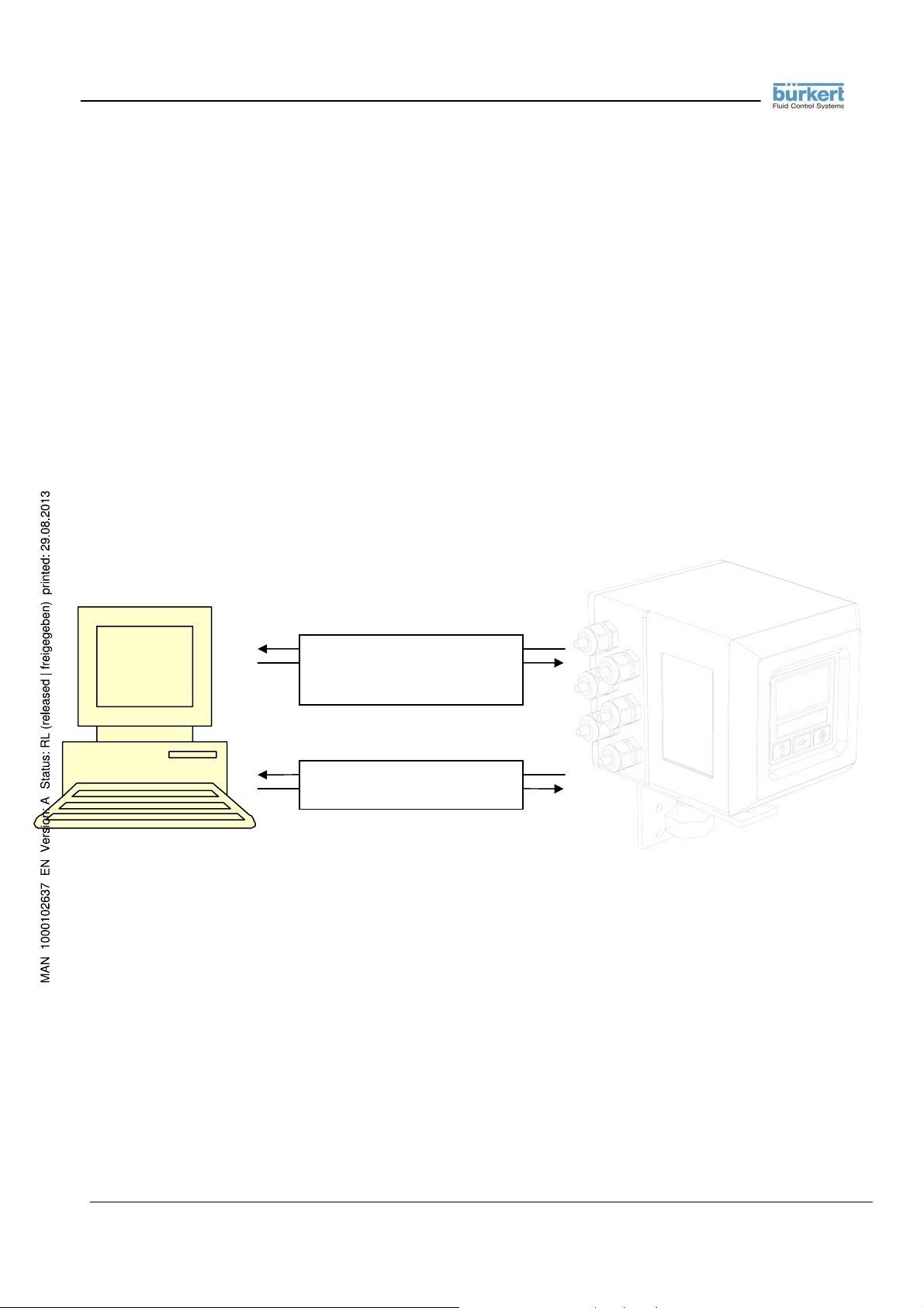
RS 232 port
RS 485 por
DPP protocol
HTP protocol
MODBUS protocol
DPP protocol
MODBUS protocol
RS 232 por
RS 485 por
- 4 - RS232_485_ETP_MODBUS_BU_REV02.doc
Page 5

3. DPP (DATA PACKET PR OTOCOL)
3.1. INTRODUCTION TO DATA PACKET PROTOCOL
With Data Packet Protocol it is possible to communicate with the flow meter through protocols with data
packets.
The protocols with data packets available for the flow meter are BCP protocol (Basic Communication
protocol) and the ETP protocol (Encapsulated Transfer protocol)
The flow meter have two serial port, the RS 232 port and the RS 485 port.
When the aux module with the RS 232 port is present in the flow meter, the menu
have the function «RS232 pr.» for the selection of the protocol type.
When the DPP setting is selected in the
possible to send command to RS 232 port of the flow meter with the protocol BCP or with the protocol ETP.
When the flow meter have the option of the MODBUS protocol, the menu
function «RS485 pr.» for the selection of the protocol type.
The possible selections are MODBUS or DPP.
When the DPP setting is selected in the
possible to send command to RS 485 port of the flow meter with the protocol BCP or with the protocol ETP.
If the flow meter don’t have the MODBUS option, the
Communication» and the default protocol type for the RS 485 port is DPP.
For the use of the commands and the structure of the BCP protocol see the relative section.
For the use of the commands and the structure of the ETP protocol see the relative section.
function «RS232 pr.» of the menu «7-Communication», it is
function «RS485 pr.» of the menu «7-Communication», it is
«7-Communication»
«7-Communication» have the
function «RS485 pr.» is not present in the menu «7-
3.2. BCP PROTOCOL (BASIC COMMUNICATION PROTOCOL)
3.2.1. INTRODUCTION
The BCP protocol is a set of formatted commands based on an index.
It is possible to read data from the flow meter as Process data or the Data Logger and it is possible to send command
to the flow meter as the start stop batch for example.
The protocol is available for the RS 232 and for the RS 485 serial port.
3.2.2. DATA WORD FORMAT
The data bytes travelling in serial form on the communication line are enclosed in
10 bits:
1 START BIT
8 DATA BITS = 1 BYTE DI DATI
1 STOP BIT
Each word contains one byte of data plus additional bits which serve to synchronise and make the communication
safer. These extra bits are added automatically in the transmission phase by the transmitter integrated circuit. In the
words
which have a fixed length of
- 5 - RS232_485_ETP_MODBUS_BU_REV02.doc
Page 6

reception phase, the reverse operation is executed by the receiver integrated circuit: the eight data bits are extracted
and the others are eliminated. These operations are executed entirely on a hardware level.
The 8 data bits must be serialised staring from bit 0 (the least significant one).
3.2.3. DATA BLOCK FORMAT
Communication takes place through data blocks or packs of variable length which do not exceed 256 bytes overall. A
data block or pack is composed thus::
• ADDRESS TO, Containing the address of the device the block is sent to;
• ADDRESS FROM, Containing the address of the device which sent the block;
• COMMAND, Containing the command code the block refers to;
• LENGTH, Containing the length of the data block in bytes
• DATA BYTES, The block of data of variable length from zero to 250
• CRC CHECKSUM BYTE, Calculated in the following way:
1. CRC initialised to zero
2. CRC rotated to the left by one bit
3. CRC = CRC + block bytes
The process is repeated starting from point 2. for all the block bytes, excluding CRC..
NOTE:
The CRC must be subjected to an operation of
The difference is shown in the following example:
byte value: 10100010
shifting : 1 <= 0100010 <= 0
rotating: 1 1 <= 0100010 <= 1
A block can contain a maximum of 90 data bytes. A block which does not contain data bytes is formed solely by
ADDRESS TO + ADDRESS FROM + COMMAND + LENGTH + CRC CHECKSUM, with LENGTH value equal to
zero.
rotation to the left
and not just a simple
shift
operation.
3.2.4. COMMUNICATION SPEED
The millennium series instruments have 4 communication speeds::
• 4800 bps
• 9600 bps
• 19200 bps
• 38400 bps
3.2.5. SERIAL PORT SETTINGS FOR RS 232 AND RS 485
Serial port settings:
• Data bits: 8
• Parity: none (no parity)
• Stop bits: 1
• Flow control: none (no control lines no xon/xoff characters used)
- 6 - RS232_485_ETP_MODBUS_BU_REV02.doc
Page 7

3.2.6. COMMAND FORMATS
A
command
command is the return of one block with the requested data having the same command code + 128 (80H). The
following command codes are available:
codice Action performed by the measuring device after receiving the command.
0 Send the
1 Send the
2 Send the
3 Receive
4,5,6,7,9,
10,13
8
11 Send events data(ML210/211/212)
12 Send
14
NOTE: the commands indicated with the term "RESERVED" are used during factory calibration and diagnosis, are
In this description, the command codes in hexadecimal and (decimal) format and the related data format are shown.
The numeration of the bits is from 0 (LSB) to 15 (MSB). The numeration of the bytes received is from 0 to N, where 0
is the first byte received and N is the last.
is defined as an operating code of 1 byte specifying the type of operation required. The reply to this
type of instrument
process data
data logger’s data
date and time
RESERVED
Send or receive data for batch
min/max
Set set-point
protected by a special password and must not be used by the user under any circumstance.
(ML210/211/212)
(ML212)
and
version
(for all models)
(ML210/211/212)
(ML210/211/212)
(ML210 / ML3-F1)
of the software ( all model )
reset the enabled totalizers
( all model )
3.2.7. READING THE TYPE OF INSTRUMENT AND THE SOFTWARE VERSION
Command code: 0
Command format: ADDRESS TO + ADDRESS FROM + 00H + 00H + CRC CHECKSUM
Reply data format: bytes 0..5: device name («ML 210»)
byte 6: software version (major number)
byte 7: software version (minor number)
bytes 8-9: (16 bits unsigned integer, byte 8=MSB):
hardware / software enabling flags, bit 0 = LSB, bit 15 = MSB:
bits Functions ML210/211/3f1 Functions ML212
0-2 current access level (0..7) current access level (0..7)
3 channel 1 impulses in use impulses for volume in use
4 channel 2 impulses in use duty cycle actuator type in use
5 channel 1 frequency in use frequency for flow rate in use
6 channel 2 frequency in use frequency for actuator in use
7 scale range 2 in use on/off type actuator in use
8 specific weight in use specific weight in use
9 additional output 3 present additional output 3 present
10 additional output 4 present additional output 4 present
11 output 4..20 mA 2 present output 4..20 mA 2 present
12 RS232 present input on/off n.2 present
13 batching functions active analog inputs 1 and 2 present
14 output 4..20 mA 2 present output 4..20 mA 1 present
15 RS485 present RS485 present
- 7 - RS232_485_ETP_MODBUS_BU_REV02.doc
Page 8

EXAMPLE:
want to send the command 00H to a measuring device located at address 11H (17 decimal).The device
that interrogates the network has the address FFH (255 decimal). The block to send will be composed thus
address of the measuring device to interrogate (ADDRESS TO)
|
| address of the device that interrogates the network (ADDRESS FROM)
| |
| | command for reading TYPE of INSTRUMENT (COMMAND)
| | |
| | | data block length (LENGTH)
| | | |
| | | | checksum of the entire block (CRC CHECKSUM)
| | | | |
11H FFH 00H 00H 84H
The reply from the measuring device will be the following:
address of the device that interrogated the network and which now must receive the reply (ADDRESS TO)
|
| address of the measuring device which sent the message (ADDRESS FROM)
| |
| | command for reading the TYPE of INSTRUMENT + 80H (128 dec.) (COMMAND)
| | |
| | | length of the data block (=10 bytes) (LENGTH)
| | | |
| | | | type of instrument («ML 200»)
| | | | |
| | | | | versione software (major.minor)
| | | | | |
| | | | | | hardware / software enabling flags
| | | | | | |
| | | | | | | CRC CHECKSUM)
| | | | | | | |
FFH 11H 80H 0AH 4D 4C 20 32 30 30H 01 02H C0 08H 21H
The measuring device has replied that it is an ML200, that its software version is the 1.02, that it has enabled the
RS485 serial port, that the output is 4..20mA and that it is using impulse emission on channel 1 (this last information is
taken from the hardware / software enabling flags).
3.2.8. READING PROCESS DATA FROM ML 210
The process data is contained in a memory block which the user can request whole or in part, depending on the
content of the two command control bytes. Byte 0 (offset) indicates which will be the first data byte of the block to
send, whilst byte 1 specifies the number of successive data bytes we want. In this way we can obtain exactly the data
we want or several pieces of data at the same time.
Command code: 01
Command format: ADDRESS TO
+ ADDRESS FROM
+ 01H
+ 02H
+ byte 0: offset – start of block to transmit
+ byte 1: length of block to transmit
+ CRC CHECKSUM
- 8 - RS232_485_ETP_MODBUS_BU_REV02.doc
Page 9

Reply data format when the sending of the entire block is requested (byte 0 = 0 and byte 1 = 46):
bytes 0-3: (32 bit single precision IEEE floating point, MSB first) flow rate in %
bytes 4-7: (32 bit single precision IEEE floating point, MSB first) flow rate scale range in t.u.
bytes 8-11: (32 bit single precision IEEE floating point, MSB first) flow rate in t.u.
bytes 12-16: (5 bytes ASCII) flow rate measurement unit
bytes 17-19: (3 bytes ASCII) measurement unit of the counters
byte 20: (8 bits integer) number of decimals after the point for totalizers display
byte 21: (8 bits integer) number of decimals after the point for flow rate display
bytes 22-25: (32 bit long integer, MSB first) totalizer for TOTAL volume +
bytes 26-29: (32 bit long integer, MSB first) totalizer for PARTIAL volume bytes 30-33: (32 bit long integer, MSB first) totalizer for TOTAL volume - ( or ML210 dosage quantity)
bytes 34-37: (32 bit long integer, MSB first) totalizer for PARTIAL volume - (or ML210 dosed quantity)
bytes 38-41: (32 bit long integer, MSB first) clock expressed in minutes starting from 01-01-1992
bytes 42-43: (16 bit unsigned integer, MSB first) process flags:
bit 0 =1 if the excitation is too fast for the sensor connected
bit 1 =1 if the maximum alarm is active
bit 2 =1 if the minimum alarm is active
bit 3 =1 if the flow rate exceeds the scale range value (overflow)
bit 4 =1 if one or more output impulses are saturated (too many impulses to emit)
bit 5 =1 if the measurement signal is highly disturbed or if the sensor is disconnected
bit 6 =1 if the measurement tube is empty
bit 7 =1 if the circuit powering the coils is not working or the sensor is disconnected
bit 8 =1 if the second measurement scale is active
bit 9 =1 if the flow rate is lower than the cut-off threshold
bit10=1 if the flow rate is negative
bit11=1 if a new measurement value calculated for the display is available
bit12=1 if the counter block signal is active
bit13=1 if dosing is in progress
bit14=1 if a calibration cycle is in progress
bit15=1 if a flow rate simulation is in progress
byte 44: (8 bits integer) measurement samples per second (Hz)
byte 45: (8 bits integer) measurement dynamic variation as a %
To request the transmission of a single parameter, assign the values of byte 0 and byte 1 in the request as follows,
bearing in mind that the data in the memory block has fixed positions:
PARAMETER TO READ Byte 0 Byte 1
Flow rate in % 0 4
Scale range of the flow rate in technical units 4 4
Flow rate in technical units 8 4
Flow rate measurement unit 12 5
Totalizers measurement unit 17 3
Decimal figures for the totalizers 20 1
Decimal figures for flow rate display 21 1
Totalizer for TOTAL volume + 22 4
Totalizer for PARTIAL volume + 26 4
Totalizer for TOTAL volume - (or dosage quantity) 30 4
Totalizer for PARTIAL volume -(or dosed quantity) 34 4
Date and time in minutes 38 4
Process flags 42 2
Measurement samples per second in Hz 44 1
Measurement dynamic variation in % 45 1
NOTES: The values in the “32 bits single precision IEEE floating point” format are floating point numbers which can
be represented during writing by any decimal digits. To keep the same numerical format visible on the
instrument display however, it is necessary to calculate the decimal figures with a rather complex
algorithm which takes account of instrument precision, flow rate measurement unit, etc. For this purpose
- 9 - RS232_485_ETP_MODBUS_BU_REV02.doc
Page 10

and to avoid useless calculations, the number of decimals to use to represent the flow rate values is
supplied separately (byte position 21).
The counters are expressed with a 32 bit integer. The «counter decimal figures» parameter, indicates the point position
starting from the right: 0 = no decimal, 1=1 decimal figure, and so on.
The date and time are expressed with a 32 bit integer containing the number of minutes elapsed since 01-01-1992. To
calculate the date starting from this number, see the programming examples at the end of this manual.
3.2.9. READING PROCESS DATA FROM ML 211
This command is similar to the preceding one and differs from it only for the quantity of the data given.
Command code: 01
Command format: ADDRESS TO
+ ADDRESS FROM
+ 01H
+ 02H
+ byte 0: offset – start of block to transmit
+ byte 1: length of block to transmit
+ CRC CHECKSUM
Reply data format when the sending of the entire block is requested (byte 0 = 0 and byte 1 = 78):
bytes 0-3: (32 bit single precision IEEE floating point, MSB first) flow rate in %
bytes 4-7: (32 bit single precision IEEE floating point, MSB first) flow rate scale range in t.u.
bytes 8-11: (32 bit single precision IEEE floating point, MSB first) flow rate in t.u.
bytes 12-16: (5 bytes ASCII) flow rate measurement unit
bytes 17-19: (3 bytes ASCII) measurement unit of the counters
byte 20: (8 bits integer) number of decimals after the point for volume totalizers display
byte 21: (8 bits integer) number of decimals after the point for flow rate display
bytes 22-25: (32 bits long integer, MSB first) totalizer for volume +
bytes 26-29: (32 bits long integer, MSB first) totalizer for volume bytes 30-33: (32 bits long integer, MSB first) totalizer for energy +
bytes 34-37: (32 bits long integer, MSB first) totalizer for energy bytes 38-41: (32 bit long integer, MSB first) clock expressed in minutes starting from 01-01-1992
bytes 42-44: 3 x (8 bits unsigned char) 3 bytes of process flags:
byte 0:
bit 0 =0 (not used)
bit 1 =1 if the flow rate is lower than the cut-off threshold
bit 2 =1 if the flow rate is negative
bit 3 =1 if a new measurement value calculated for the display is available
bit 4 =1 if the counter block signal is active
bit 5 =0 (non used)
bit 6 =1 if a calibration cycle is in progress
bit 7 =1 if a flow rate simulation is in progress
byte 1:
bit 0 =1 if the temperature sensors are disconnected or broken
bit 1 =1 if the maximum alarm for the flow rate is active
bit 2 =1 if the minimum alarm for the flow rate is active
bit 3 =1 if a measure exceeds the scale range value (overflow)
bit 4 =1 if one or more output impulses are saturated (too many impulses to emit)
bit 5 =1 if the measurement signal is highly disturbed or if the sensor is disconnected
bit 6 =1 if the measurement tube is empty
bit 7 =1 if the circuit powering the coils is not working or the sensor is disconnected
- 10 - RS232_485_ETP_MODBUS_BU_REV02.doc
Page 11

byte 2:
bit 0 =1 if the maximum alarm for the thermal power is active
bit 1 =1 if the minimum alarm for the thermal power is active
bit 2 =1 if the maximum alarm for the delta T is active
bit 3 =1 if the minimum alarm for the delta T is active
bit 4 =1 if the maximum alarm for the temperature T1 is active
bit 5 =1 if the minimum alarm for the temperature T1 is active
bit 6 =1 if the maximum alarm for the temperature T2 is active
bit 7 =1 if the minimum alarm for the temperature T2 is active
byte 45: (8 bits integer) number of measure samples per second (hertz)
bytes 46-49: (32 bits single precision IEEE floating point, MSB first) thermal power in %
bytes 50-53: (32 bits single precision IEEE floating point, MSB first) full scale thermal power in t.u.
bytes 54-57: (32 bits single precision IEEE floating point, MSB first) thermal power in t.u.
bytes 58-62: (5 bytes ASCII) measure unit for the thermal power
bytes 63-66: (4 bytes ASCII) measure unit for the thermal energy
byte 67: (8 bits integer) number of decimals after the point for energy totalizers display
byte 68: (8 bits integer) number of decimals after the point for thermal power display
byte 69: (8 bits integer) measure unit for the temperature (C or F degrees)
bytes 70-73: (32 bits single precision IEEE floating point, MSB first) delta T value in t.u.
bytes 74-77: (32 bits single precision IEEE floating point, MSB first) T1 temperature in t.u.
bytes 78-81: (32 bits single precision IEEE floating point, MSB first) T2 temperature in t.u.
To request the transmission of a single parameter, assign the values of byte 0 and byte 1 in the request as follows,
bearing in mind that the data in the memory block has fixed positions:
PARAMETRO DA LEGGERE Byte 0 Byte 1
Flow rate in % 0 4
Full scale flow rate 4 4
Flow rate in technical units 8 4
Measure unit for the flow rate 12 5
Measure unit for the volume totalizers 17 3
Number of decimal digit after the point for volume totalizers 20 1
Number of decimal digit after the point for the flow rate 21 1
Totalizer for volume + 22 4
Totalizer for volume - 26 4
Totalizer for thermal energy + 30 4
Totalizer for thermal energy - 34 4
Time and date expressed in minutes 38 4
Process flags 42 3
Number of samples per second in Hz 45 1
Thermal power in % 46 4
Full scale thermal power in t.u. 50 4
Thermal power in t.u. 54 4
Measure unit for the thermal power 58 5
Measure unit for the thermal energy 60 3
Number of decimal digit after the point for energy totalizers 63 1
Number of decimal digit after the point for the th. power 64 1
T in technical units 65 1
Delta T in t.u. 66 4
T1 value in t.u. 70 4
T2 value t.u. 74 4
NOTE: For the numeric representations and the number of decimal digits, see the preceding point.
- 11 - RS232_485_ETP_MODBUS_BU_REV02.doc
Page 12

3.2.10. READING PROCESS DATA FROM ML212
This command is similar to the preceding one and differs from it only for the quantity of the data given.
Command code: 01
Command format: ADDRESS TO
+ ADDRESS FROM
+ 01H
+ 02H
+ byte 0: offset – start of block to transmit
+ byte 1: length of block to transmit
+ CRC CHECKSUM
Reply data format when the sending of the entire block is requested (byte 0 = 0 and byte 1 = 59):
bytes 0-3: (32 bit single precision IEEE floating point, MSB first) flow rate in %
bytes 4-7: (32 bit single precision IEEE floating point, MSB first) flow rate scale range in t.u.
bytes 8-11: (32 bit single precision IEEE floating point, MSB first) flow rate in t.u.
bytes 12-16: (5 bytes ASCII) flow rate measurement unit
bytes 17-19: (3 bytes ASCII) measurement unit of the counters
byte 20: (8 bits integer) number of decimals after the point for volume totalizers display
byte 21: (8 bits integer) number of decimals after the point for flow rate display
bytes 22-25: (32 bits long integer, MSB first) totalizer for volume +
bytes 26-29: (32 bits long integer, MSB first) totalizer for volume -
bytes 30-33: (32 bits long integer, MSB first) totalizer for actuator closing pulses
bytes 34-37: (32 bits long integer, MSB first) totalizer for actuator opening pulses
bytes 38-41: (32 bit long integer, MSB first) clock expressed in minutes starting from 01-01-1992
bytes 42-43: (16 bit unsigned integer, MSB first) process flags:
bit 0 =1 if the deviation alarm is active
bit 1 =1 if the maximum alarm is active
bit 2 =1 if the minimum alarm is active
bit 3 =1 if the flow rate exceeds the scale range value (overflow)
bit 4 =1 if one or more output impulses are saturated (too many impulses to emit)
bit 5 =1 if the measurement signal is highly disturbed or if the sensor is disconnected
bit 6 =1 if the measurement tube is empty
bit 7 =1 if the circuit powering the coils is not working or the sensor is disconnected
bit 8 =1 if the measure sample rate is too high for the sensor
bit 9 =1 if the flow rate is lower than the cut-off threshold
bit10=1 if the flow rate is negative
bit11=1 if a new measurement value calculated for the display is available
bit12=1 if the counter block signal is active
bit13=1 if the actuator positioning alarm is active
bit14=1 if a calibration cycle is in progress
bit15=1 if a flow rate simulation is in progress
byte 44: (8 bits integer) measurement samples per second (Hz)
byte 45: (8 bits integer) measurement dynamic variation as a %
bytes 46-49: (32 bits single precision IEEE floating point, MSB first) set-point value in %
bytes 50-53: (32 bits single precision IEEE floating point, MSB first) regulator output value in %
bytes 54-57: (32 bits single precision IEEE floating point, MSB first) deviation value in %
byte 58: (1 byte ASCII) regulator status flags:
bit 0 =1 if the regulator is in “manual” mode
bit 1 =1 if the regulator output is inverted
bit 2 =1 if the regulator output is in “safety” state
bit 3 =1 if the deviation alarm is active
bit 4 =1 if the actuator alarm is active
- 12 - RS232_485_ETP_MODBUS_BU_REV02.doc
Page 13

bit 5 =1 if the measure at the AIN1 input is out of range
bit 6 =1 if the measure at the AIN1 input is out of range
To request the transmission of a single parameter, assign the values of byte 0 and byte 1 in the request as follows,
bearing in mind that the data in the memory block has fixed positions:
PARAMETER TO READ Byte 0 Byte 1
Flow rate in % 0 4
Full scale flow rate 4 4
Flow rate in technical units 8 4
Measure unit for the flow rate 12 5
Measure unit for the volume totalizers 17 3
Number of decimal digit after the point for volume totalizers 20 1
Number of decimal digit after the point for the flow rate 21 1
Totalizer for volume + 22 4
Totalizer for volume - 26 4
Totalizer for actuator closing impulses 30 4
Totalizer for actuator opening impulses 34 4
Date and time in minutes 38 4
Process flags 42 2
Measurement samples per second in Hz 44 1
Measurement dynamic variation in % 45 1
Set-point value in % 46 4
Regulator output value in % 50 4
Deviation value in % 54 4
Regulator status flags 58 1
NOTE: For the numeric representations and the number of decimal digits, see the preceding point.
3.2.11. READING PROCESS D ATA FROM ML 3F1
The process data is contained in a memory block which the user can request whole or in part, depending on the
content of the two command control bytes. Byte 0 (offset) indicates which will be the first data byte of the block to
send, whilst byte 1 specifies the number of successive data bytes we want. In this way we can obtain exactly the data
we want or several pieces of data at the same time..
Command code: 01
Command format: ADDRESS TO
+ ADDRESS FROM
+ 01H
+ 02H
+ byte 0: offset – start of block to transmit
+ byte 1: length of block to transmit
+ CRC CHECKSUM
Reply data format when the sending of the entire block is requested (byte 0 = 0 and byte 1 = 46):
bytes 0-3: (32 bit single precision IEEE floating point, MSB first) flow rate in %
bytes 4-7: (32 bit single precision IEEE floating point, MSB first) flow rate scale range in t.u.
bytes 8-11: (32 bit single precision IEEE floating point, MSB first) flow rate in t.u.
bytes 12-16: (5 bytes ASCII) flow rate measurement unit
bytes 17-19: (3 bytes ASCII) measurement unit of the counters
byte 20: (8 bits integer) number of decimals after the point for totalizers display
byte 21: (8 bits integer) number of decimals after the point for flow rate display
bytes 22-25: (32 bit long integer, MSB first) totalizer 1
bytes 26-29: (32 bit long integer, MSB first) totalizer 2
bytes 30-33: (32 bit long integer, MSB first) everytime to 0
- 13 - RS232_485_ETP_MODBUS_BU_REV02.doc
Page 14

bytes 34-37: (32 bit long integer, MSB first) everytime to 0
bytes 38-41: (32 bit long integer, MSB first) everytime to 0
bytes 42-43: (16 bit unsigned integer, MSB first) process flags
bit 0 =1 if the excitation is too fast for the sensor connected
bit 1 =1 if the maximum alarm is active
bit 2 =1 if the minimum alarm is active
bit 3 =1 if the flow rate exceeds the scale range value (overflow)
bit 4 =1 if one or more output impulses are saturated (too many impulses to emit)
bit 5 =1 if the measurement signal is highly disturbed or if the sensor is disconnected
bit 6 =1 if the measurement tube is empty
bit 7 =1 if the circuit powering the coils is not working or the sensor is disconnected
bit 8 =1 if the second measurement scale is active
bit 9 =1 if the flow rate is lower than the cut-off threshold
bit10=1 if the flow rate is negative
bit11=1 if a new measurement value calculated for the display is available
bit12=1 if the counter block signal is active
bit13=1 if dosing is in progress
bit14=1 if a calibration cycle is in progress
bit15=1 if a flow rate simulation is in progress
byte 44: (8 bits integer) measurement samples per second (Hz)
byte 45: (8 bits integer) measurement dynamic variation as a %
To request the transmission of a single parameter, assign the values of byte 0 and byte 1 in the request as follows,
bearing in mind that the data in the memory block has fixed positions:
PARAMETRO DA LEGGERE Byte 0 Byte 1
Flow rate in % 0 4
Scale range of the flow rate in technical units 4 4
Flow rate in technical units 8 4
Flow rate measurement unit 12 5
Totalizers measurement unit 17 3
Decimal figures for the totalizers 20 1
Decimal figures for flow rate display 21 1
Totalizer for T1 22 4
Totalizer for T2 26 4
Process flags 42 2
Measurement samples per second in Hz 44 1
Measurement dynamic variation in % 45 1
NOTES: The values in the “32 bits single precision IEEE floating point” format are floating point numbers which can
be represented during writing by any decimal digits. To keep the same numerical format visible on the
instrument display however, it is necessary to calculate the decimal figures with a rather complex
algorithm which takes account of instrument precision, flow rate measurement unit, etc. For this purpose
and to avoid useless calculations, the number of decimals to use to represent the flow rate values is
supplied separately (byte position 21).
The counters are expressed with a 32 bit integer. The «counter decimal figures» parameter, indicates the
point position starting from the right: 0 = no decimal, 1=1 decimal figure, and so on.
The date and time are expressed with a 32 bit integer containing the number of minutes elapsed since 0101-1992. To calculate the date starting from this number, see the programming examples at the end of
this manual.
- 14 - RS232_485_ETP_MODBUS_BU_REV02.doc
Page 15

3.2.12. SETTING THE SET-POINT OF THE ML212
With this command it is possible to send the set-point value in % format to the ML202. If the value is positive, this is
intended as REMOTE set-point value and must be refreshed continuously. The maximum time between two refreshes it
is regulated by the same timer used to signal the deviation alarm condition and thus it is freely changeable. If the
value sent is negative, it is considered as LOCAL set-point value and in this case it is not necessary to refresh it
continuously. In any cases the regulator receives the absolute value of the number sent.
Command code: 14
Command format: ADDRESS TO
+ ADDRESS FROM
+ 0EH
+ 04H
+ 32 bits IEEE floating point containing the set-point value in %
+ CRC CHECKSUM
The same number is returned as answer by the ML212
3.2.13. READING THE INTERNAL DATA-LOGGER DATA OF ML210 / 211 / 212
The data logger can be read one record at a time with this command. If we assign the value AAH to the byte
specifying the address (byte 0), the data logger is cancelled. If we request the address of a record not present in the
memory, the returned data has no sense. For this purpose we recommend starting from the request for record 0 and
to check the number of records present in the memory which is returned by the measuring device.
Command code : 02
Command format: ADDRESS TO
+ ADDRESS FROM
+ 02H
+ 01H
+ byte 0: index of the data logger data to read, AAH to cancel the entire content
+ CRC CHECKSUM
Reply data format in the case where there are registrations present:
byte 0: (8 bits integer) number of record requested
byte 1: (8 bits integer) total number of records present in the memory
bytes 2-5: (32 bits long integer, MSB first) data saving time and date expressed in minutes starting from 01-01-
1992
bytes 6-9: (32 bits long integer, MSB first) data counted +
bytes 10-13: (32 bits long integer, MSB first) data counted bytes 14-17: (32 bits single precision IEEE floating point, MSB first) portata in u.t.
bytes 18-20: (3 bytes ASCII) (3 bytes ASCII) counter measurement unit
byte 21: (8 bits integer) number of decimal figures after the point for counter display
bytes 22-26: (5 bytes ASCII) flow rate t.u.
byte 27: (8 bits integer) number of decimal figures after the point for flow rate
Reply data format in the case where registrations are NOT present or the data logger is disabled
byte 0: (8 bits integer) requested record number
byte 1: (8 bits integer) total number of records present in the memory
Reply data format in the case where the AAH cancellation code is sent:
byte 0: (8 bits integer) AAH code.
NOTE: The time and date of sample collection is expressed in minutes starting from 01/01/1992. For conversion, see
the programming examples at the end of this manual.
- 15 - RS232_485_ETP_MODBUS_BU_REV02.doc
Page 16

3.2.14. READING THE EVENTS ON INTERNAL DATA-LOGGER DATA OF ML210 / 211 / 212
The data logger can be read one record at a time with this command. If we assign the value AAH to the byte
specifying the address (byte 0), the data logger is cancelled. If we request the address of a record not present in the
memory, the returned data has no sense. For this purpose we recommend starting from the request for record 0 and
to check the number of records present in the memory which is returned by the measuring device..
Command code : 11
Command format: ADDRESS TO
+ ADDRESS FROM
+ 0BH
+ 01H
+ byte 0: index of the data logger data to read, AAH to cancel the entire content
+ CRC CHECKSUM
Reply data format in the case where there are registrations present:
byte 0: (8 bits integer) number of record requested
byte 1: (8 bits integer) total number of records present in the memory
bytes 2-5: (32 bits long integer, MSB first) data saving time and date expressed in minutes starting
from 01-01-1992
bytes 6-9: (32 bits long integer, MSB first) flags events
bit 00: error sensor RTD / batch alarm
bit 01: alarm max flow
bit 02: alarm min flow
bit 03: alarm overflow
bit 04: alarm overflow pulse
bit 05: input error
bit 06: pipe empty
bit 07: coils interrupt
bit 08: alarm max t. power
bit 09: alarm min t. power
bit 10: alarm max delta T
bit 11: alarm min delta T
bit 12: alarm max T1
bit 13: alarm min T1
bit 14: alarm max T2
bit 15: alarm min T2
bit 16: current loop open
bit 17: power supply error
Code 000300FFH or 0003FFFFH = means converter switch on
Reply data format in the case where registrations are NOT present or the data logger is disabled
byte 0: (8 bits integer) requested record number
byte 1: (8 bits integer) total number of records present in the memory
Reply data format in the case where the AAH cancellation code is sent:
byte 0: (8 bits integer) AAH code.
NOTE: The time and date of sample collection is expressed in minutes starting from 01/01/1992. For conversion, see
the programming examples at the end of this manual.
- 16 - RS232_485_ETP_MODBUS_BU_REV02.doc
Page 17

3.2.15. READING THE MAX-MIN ON INTERNAL DATA-LOGGER DATA OF ML210
The data logger can be read one record at a time with this command. If we assign the value AAH to the byte
specifying the address (byte 0), the data logger is cancelled. If we request the address of a record not present in the
memory, the returned data has no sense. For this purpose we recommend starting from the request for record 0 and
to check the number of records present in the memory which is returned by the measuring device..
Command code: 12
Command format: ADDRESS TO
+ ADDRESS FROM
+ 0CH
+ 01H
+ byte 0: index of the data logger data to read, AAH to cancel the entire content
+ CRC CHECKSUM
Reply data format in the case where there are registrations present:
bytes 0-3:(32 bits IEEE floating point, MSB first) MAX FLOW RATE IN T.U.
bytes 4-7:(32 bits IEEE floating point, MSB first) MIN FLOW RATE IN T.U.
3.2.16. LETTURA VALORI MIN-MAX DEL LOGGER INTERNO DI ML211
The data logger can be read one record at a time with this command. If we assign the value AAH to the byte
specifying the address (byte 0), the data logger is cancelled. If we request the address of a record not present in the
memory, the returned data has no sense. For this purpose we recommend starting from the request for record 0 and
to check the number of records present in the memory which is returned by the measuring device..
Command code: 12
Command format: ADDRESS TO
+ ADDRESS FROM
+ 0CH
+ 01H
+ byte 0: index of the data logger data to read, AAH to cancel the entire content
+ CRC CHECKSUM
Reply data format in the case where there are registrations present :
bytes 0-3:(32 bits IEEE floating point, MSB first) MAX FLOW RATE IN T.U.
bytes 4-7:(32 bits IEEE floating point, MSB first) MIN FLOW RATE IN T.U.
bytes 8-11:(32 bits IEEE floating point, MSB first) MAX T. POWER IN T.U.
bytes 12-15:(32 bits IEEE floating point, MSB first) MIN T. POWER IN T.U.
bytes 16-19:(32 bits IEEE floating point, MSB first) deltaT MAX IN T.U.
bytes 20-23:(32 bits IEEE floating point, MSB first) deltaT MIN IN T.U.
bytes 24-27:(32 bits IEEE floating point, MSB first) T1 MAX IN T.U.
bytes 28-31:(32 bits IEEE floating point, MSB first) T1 MIN IN T.U.
bytes 32-35:(32 bits IEEE floating point, MSB first) T1 MAX IN T.U.
bytes 36-39:(32 bits IEEE floating point, MSB first) T1 MIN IN T.U.
- 17 - RS232_485_ETP_MODBUS_BU_REV02.doc
Page 18

3.2.17. WRITING THE DATE AND TIME OR RESET THE ENABLED TOTALIZERS
Codice comando: 03
Formato comando: ADDRESS TO
+ ADDRESS FROM
+ 03H
+ 04H
+ 32 bits long integer containing the date and time expressed in minutes starting from 01-01-
1992, or the value FFFFFFFFH to reset the totalizers
the most significant byte must be sent first.
+ CRC CHECKSUM
Reply data format: the same block is returned containing the current clock value in minutes. If the value sent is
outside the limits, (date beyond 31-12-2091), the clock restarts from 01-01-1992. In case
of totalizers reset, the same value FFFFFFFFH is returned.
3.2.18. SEND / RECEVE BATCH PROCESS DATA ML210 /ML 3F1
The batch data can be read or written with the command described below. Th command contains an OPCODE byte
specifying the operation type to be done on the selected batch data. With these commands one of the 16 batch
memories can be written, read or it can be set as active batch process. Once set a selected batch memory, it will be
possible start, stop or reset the batch process. To set a batch memory as active batch process, a write or read
command can be used indifferently, but the bit 6 of the OPCODE must be set to 1
– Command for reading a batch data memory:
Command code: 08
Command format: ADDRESS TO
+ ADDRESS FROM
+ 08H
+ 01H (1 DECIMALE)
+ OPCODE byte, operation code:
bits 0..4 = number of the batch memory to be read (0..15)
bit 5 = must be set to zero
bit 6 = 1 if this batch memory must be set as active batch process, 0 if this batch
memory is to be read only.
bit 7 = must be set to zero
+ CRC CHECKSUM
Format of the returned data: 16 bytes containing the batch data for the selected memory:
bytes 0-7: (8 bytes ASCII) memory batch name (allowed characters: 0..9, a..z, A..Z, space (32 DEC, 20 HEX))
bytes 8-9: (2 bytes 16 bit unsigned integer, MSB first) number of batch processes done for this batch memory.
bytes 10-11: (2 bytes 16 bit unsigned integer, MSB first) value of the safety batch timer expressed in tenths of
seconds.
bytes 12-15: (4 bytes 32 bits unsigned long integer, MSB first) batch quantity value expressed in the same units and
with the same decimal digits of the volume counters.
- 18 - RS232_485_ETP_MODBUS_BU_REV02.doc
Page 19

– Comando per scrivere i dati su una memoria di dosaggio:
Command code: 08
Command format: ADDRESS TO
+ ADDRESS FROM
+ 08H
+ 11H (17 DECIMAL)
+ OPCODE byte, operation code:
bits 0..4 = number of the batch memory to be written (0..15)
bit 5 = must be set to one
bit 6 = 1 if this batch memory must be set as active batch process, 0 if this batch
memory is to be written only.
bit 7 = must be set to zero
+ 16 bytes of data to be written on the batch memory:
bytes 0-7: (8 bytes ASCII) batch memory name (allowed characters: 0..9, a..z, A..Z, space
(32 DEC, 20 HEX))
bytes 8-9: (2 bytes 16 bit unsigned integer, MSB first) number of batch processes done for
this batch memory.
bytes 10-11: (2 bytes 16 bit unsigned integer, MSB first) value of the batch safety timer
expressed in tenths of seconds.
bytes 12-15: (4 bytes 32 bits unsigned long integer, MSB first) batch quantity value
expressed in the same units and with the same decimal digits of the volume
counters.
+ CRC CHECKSUM
Format of the returned data: 16 bytes containing the same batch data for the selected memory sent (if there were any
characters or values not allowed, they are corrected to the right values). The data format are the same of the
precedent function.
c) - Command for reading the current batch process state:
Command code: 08
Command format: ADDRESS TO
+ ADDRESS FROM
+ 08H
+ 01H (1 DECIMAL)
+ OPCODE byte = 80H (128 DECIMAL)
+ CRC CHECKSUM
Format of the returned data: 1 byte containing the batch process state:
0 = batch process is correctly terminated (pre-set quantity reached).
1 = batch process is running (the valve is opened and the counters are running).
2 = batch process is suspended (the valve is closed before the pre-set quantity is reached).
d) - Command for starting or suspending the current batch process:
Command code: 08
Command format: ADDRESS TO
+ ADDRESS FROM
+ 08H
+ 01H (1 DECIMAL)
+ OPCODE byte = 81H (129 DECIMAL)
+ CRC CHECKSUM
Format of the returned data: 1 byte containing the batch process state as described above.
- 19 - RS232_485_ETP_MODBUS_BU_REV02.doc
Page 20

e) - Command for resetting the current batch process:
Command code: 08
Command format: ADDRESS TO
+ ADDRESS FROM
+ 08H
+ 01H (1 DECIMAL)
+ OPCODE byte = 82H (130 DECIMAL)
+ CRC CHECKSUM
Format of the returned data: 1 byte containing the batch process state as described above. This command resets the
dosing quantity and the safety timer counters.
3.3. ETP PROTOCOL (ENCAPSULATED TRANSFER PROTOCOL)
3.3.1. INTRODUCTION
The ETP is a protocol owner of the converter that has the function of the read and set the parameters of the
converter through formatted strings of characters.
3.3.2. DATA WORD FORMAT
The data bytes travelling in serial form on the communication line are enclosed in
10 bits:
1 START BIT
8 DATA BITS = 1 BYTE DI DATI
1 STOP BIT
Each word contains one byte of data plus additional bits which serve to synchronise and make the communication
safer. These extra bits are added automatically in the transmission phase by the transmitter integrated circuit. In the
reception phase, the reverse operation is executed by the receiver integrated circuit: the eight data bits are extracted
and the others are eliminated. These operations are executed entirely on a hardware level.
The 8 data bits must be serialised staring from bit 0 (the least significant one).
words
which have a fixed length of
3.3.3. COMMUNICATION SPEED
The millennium series instruments have 4 communication speeds::
• 4800 bps
• 9600 bps
• 19200 bps
• 38400 bps
- 20 - RS232_485_ETP_MODBUS_BU_REV02.doc
Page 21

3.3.4. SERIAL PORT SETTINGS FOR RS 232 AND RS 485 PORT
Serial port settings:
• Data bits: 8
• Parity: none (no parity)
• Stop bits: 1
• Flow control: none (no control lines no xon/xoff characters used)
3.3.5. GENERAL INPUT SYSNTAX
The information are entered as text line strings, with one or more command-sequences terminated by the <CR>
character. The command-sequences are executed in the same order as they are found in the string. The execution of
the commands contained in the input string does not start until the <CR> character is received. The optional <LF>
character that may follows the <CR> is not considered but it is accepted because usually the Hyper-Terminal or
similar application sends also this extra character when the <CR> is sent.
As a rule, an input string is composed of one or more command-sequences, terminated by the <CR> character and
an optional <LF> character.
The command-sequence is composed by the following elements, exactly in this order:
A five-letter mnemonic command, always present
An operator, always present
An optional value, present only when requested by the operator type
An optional comment-separator, may be present if it is also present the value
A comment, present only if it is also present the comment-separator
An optional command-separator, present only if another command-sequence follows it
With the exception of the comment element, no other extra characters or spaces are allowed in the commandsequence.
Command: The commands are always represented by a five-letters mnemonic code and are case insensitive, so for
example the command MODSV can be written “MODSV”, “Modsv”, “modsv”, “mOdSv” and in any combination of
upper / lower case letters.
Operator: The operators permit to choose one of the three possible functions associated to the command at which
they are attached and they are:
READ, indicated by the ? symbol. It is used to read values.
SET, indicated by the = symbol. It is used to set values.
HELP, indicated by the =? sequence of symbols. It is used to display a set of options or a range of permissible
values related to the command.
Value: The values can be numbers, strings or special formatted fields like the date / time or the IP addresses,
depending on what it is expected by the command.
Numeric values are always checked for validity range and strings are checked for length.
- 21 - RS232_485_ETP_MODBUS_BU_REV02.doc
Page 22

IP addresses and date / time fields are checked only for the correct syntax but not for the values, so please be
careful, because in case of misspelled characters or wrong numeric values the result may be different from what it is
expected.
In case of floating-point numbers, the decimal point symbol to be used is the dot (.), not the comma (,).
Comment-separator: This is an optional element and it is indicated by the “:” symbol.
Comment: This element may be present only when the value to input belongs to a list of options, composed by
numbers and descriptions.
Normally the user doesn’t have to supply both, but in case of copying and pasting some values coming from a
previously listed configuration, this ensures the full compatibility between the output and the input formats.
Command-separator: This element is required when more than one command-sequence is submitted in an input
string and it is indicated with the “,” symbol.
For each command-sequence recognized and executed, the converter returns one of the following output types,
depending on it:
a result code, when a function execution was requested
an expression, when a parameter or a process data value was requested
a list of options or a range of values, when an help on a parameter was requested
Each answer is separated from the other by the comma symbol (the same used as command-separator).
The complete output string is terminated by a <CR><LF> sequence.
Unrecognized command-sequences are silently discarded without response and without halting the execution of the
next sequence, if it is present.
Illegal parameter’s values and operations performed in wrong contexts are reported and identified by error codes.
Result-code: The format of the results is the following: code-number:description, without any blank spaces
separating the number from the description.
There are six possible result-codes:
0:OK, the execution was correct
1:CMD ERR, wrong context, execution was not possible due to a configuration limit or wrong working conditions
2:PARAM ERR, the expected parameter was out of the allowed range
3:EXEC ERR, the execution of the command was not successful due to an internal error condition
4:RANGE ADJ, the entered parameter caused an internal automatic adjustment on other ranges
5:ACCESS ERR, the execution of the command was not possible due to an insufficient privilege level
6:BUFFER FULL, the input or the output strings exceed the maximum allowable space.
3.3.6. SPECIAL CHARACTERS
The following characters have special meaning in the protocol and thus they can’t be used for other purposes:
<CR> carriage-return character, value 13 decimal, 0D hexadecimal, terminates the input string and starts the
elaboration
<LF> line-feed character, value 10 decimal, 0A hexadecimal, may follows the <CR> but it is never considered
? question mark character, value 63 decimal, 3F hexadecimal, it is an operator character
= equal sign character, value 61 decimal, 3D hexadecimal, it is another operator character
: colon character, value 58 decimal, 3A hexadecimal, it is the comment-separator character
, comma character, value 44 decimal, 2C hexadecimal, it is the command-separator character
3.3.7. ACCESS CODE FOR FUNCTION WITH PRIVILEGE LEVEL
The access and the changing of some parameters can made only after the inserting of a level code.
This can made sending an access code corresponding to the level L2 as first command before inserting the command.
- 22 - RS232_485_ETP_MODBUS_BU_REV02.doc
Page 23

The syntax for inserting the code is: “ACODE=n” with n=access code L2
The lifecycle of the code is limited at the execution of the string command that following the code.
After the acquisition of the command the access level return at default status.
Is necessary to insert the code level every time the command or the list of the command request the insertion of the
code access greater than the default level.
If the level L2 of the converter is set to 0, then is not necessary to insert the code L2.
When the access code is not sufficient for the command, the converter return the following error code:
5:ACCESS ERR
Example of string with command for code level L2=12345 and command for reading model a software version of the
converter:
“ACODE=12345,MODSV?” + chr(13)
3.3.8. DATA BLOCK FORMAT
Communication takes place through data blocks or packs of variable length which do not exceed 256 bytes overall. A
data block or pack is composed thus::
ADDRESS TO, Containing the address of the device the block is sent to;
ADDRESS FROM, Containing the address of the device which sent the block;
BLOCK CODE, Containing the code that it indicates if after this block given there is a successive block;
BLOCK LENGTH, Containing the length of the data block in bytes
BLOCK DATA, The block of data of variable length from zero to 250 bytes
CRC CHECKSUM BYTE, Calculated in the following way:
4. CRC initialised to zero
5. CRC rotated to the left by one bit
6. CRC = CRC + block bytes
The process is repeated starting from point 2. for all the block bytes, excluding CRC..
NOTE:
The CRC must be subjected to an operation of
The difference is shown in the following example:
byte value: 10100010
shifting : 1 <= 0100010 <= 0
rotating: 1 1 <= 0100010 <= 1
NOTE:
The code to insert in BLOCK CODE can have the following values:
91 decimal (5B hex)
Insert 90 decimal when BLOCK DATA length is smaller or equal to 250 characters
If the length of the block data is greater than 250 characters, split the block data in packets of 250
Every packets with BLOCK DATA of 250 characters have BLOCK CODE equal to 91 dec.
The last block of data with numbers of byte smaller or equal to 250 have BLOCK CODE with 90 dec.
90 decimal (5A hex)
characters.
rotation to the left
and not just a simple
shift
operation.
- 23 - RS232_485_ETP_MODBUS_BU_REV02.doc
Page 24

3.3.9. EXAMPLE OF ETP COMAND
Reading model and software version of the converter:
mnemonic: MODSV
syntax of the command: “MODSV?”
list of the bytes and corresponding values of the command:
byte 0: address to = chr(0)
byte 1: address from = chr(170)
byte 2: block code = chr(90) (length of the next data block smaller than 250 characters)
byte 3: length = chr(7) (length of the next data block)
byte 4: block data = chr(77) = ‘M’
byte 5: block data = chr(79) = ‘O’
byte 6: block data = chr(68) = ‘D’
byte 7: block data = chr(83) = ‘S’
byte 8: block data = chr(86) = ‘V’
byte 9: block data = chr(63) = ‘?’
byte 10: carriage-return <CR> = chr(13)
byte 11: checksum = chr(239)
List of the bytes to send to the converter in hexadecimal format:
chr(0x00) + chr(0xAA) + chr(0x5A) + chr(0x08) + chr(0x4D) + chr(0x4F) + chr(0x44) + chr(0x53) +
chr(0x56) + chr(0x3F) + chr(0x0D) + chr(0xEF)
3.3.10. EXAMPLE OF RESPONSE FOR PRECECDENT ETP COMAND
Header string response:
byte 0 = chr(170)
byte 1 = chr(0)
byte 2 = chr(218) 218 dec = 0xDA hex (code 218 = length of the next data block smaller than 250 characters)
byte 3 = chr(29) number of characters of the data block = 29 bytes
Body string response:
byte 4 = 77 chr(77) = ‘M’ char 1
byte 5 = 76 chr(76) = ‘L’ char 2
byte 6 = 32 chr(32) = ‘ ’ char 3
byte 7 = 50 chr(50) = ‘2’ char 4
byte 8 = 49 chr(49) = ‘1’ char 5
byte 9 = 48 chr(48) = ‘0’ char 6
byte 10 = 32 chr(32) = ‘ ’ char 7
byte 11 = 86 chr(86) = ‘V’ char 8
byte 12 = 69 chr(69) = ‘E’ char 9
byte 13 = 82 chr(82) = ‘R’ char 10
byte 14 = 46 chr(46) = ‘.’ char 11
byte 15 = 51 chr(51) = ‘3’ char 12
byte 16 = 46 chr(46) = ‘.’ char 13
byte 17 = 54 chr(54) = ‘6’ char 14
byte 18 = 48 chr(48) = ‘0’ char 15
byte 19 = 32 chr(32) = ‘ ’ char 16
byte 20 = 77 chr(77) = ‘M’ char 17
byte 21 = 97 chr(97) = ‘a’ char 18
byte 22 = 121 chr(121) = ‘y’ char 19
- 24 - RS232_485_ETP_MODBUS_BU_REV02.doc
Page 25

byte 23 = 32 chr(32) = ‘ ’ char 20
byte 24 = 49 chr(49) = ‘1’ char 21
byte 25 = 53 chr(53) = ‘5’ char 22
byte 26 = 32 chr(32) = ‘ ’ char 23
byte 27 = 50 chr(50) = ‘2’ char 24
byte 28 = 48 chr(48) = ‘0’ char 25
byte 29 = 48 chr(48) = ‘0’ char 26
byte 30 = 55 chr(55) = ‘7’ char 27
byte 31 = 13 chr(13) = char 28
byte 32 = 10 chr(10) = char 29
byte 33 = 247 checksu
3.3.11. COMUNICATION
The above mentioned communication protocol is used to exchange data between one unit defined as the MASTER and
another unit defined as the SLAVE.
The term MASTER is used here to indicate a device capable of initiating data transmission on its own initiative.
The term SLAVE however, is used to indicate a device capable of transmitting data only in reply to a command
received.
Neither of the two types of devices can receive and transmit contemporaneously: these operations take place in two
different time phases.
Two MASTER type units cannot be connected together because both of the devices would begin to transmit
autonomously and would never succeed in synchronizing themselves.
Analogously, two SLAVE type devices could never exchange information because neither of the two is capable of
initiating communication on its own initiative.
The flow of information in both directions therefore takes place alternately using blocks containing a maximum of 95
words each. A word is composed of 10 bits in all: 1 start bit + 8 data bits + 1 stop bit.
These data blocks are received contemporaneously by all the devices connected along the communication line, but
only the device with the address equal to the one contained in the data block will be the real destined.
The words comprising the block must be sent on the serial line in a continuous mode, without dead time between one
word and the next. The maximum dead time permitted between two words must not exceed the duration of one word.
SLAVE type devices always generate a reply to every message sent to them and correctly received. In the case of
reception errors, there is no reply. In the case of command interpretation errors (incorrect format, missing parameters,
etc.) either a block without data or no reply, may be the reply depending on the case.
The that elapses between the sending of the last data word by the MASTER and the sending of the first reply word by
the SLAVE can be schematized as follows:
last word transmitted by the MASTER
|
| reply processing: time variable from 0 to 25 milliseconds at the most
| |
| | time equal to 3 complete words
| | |
| | | first word transmitted by the SLAVE as reply
| | | |
.....xxxxx| t0 | t1 |xxxxxx......
- 25 - RS232_485_ETP_MODBUS_BU_REV02.doc
Page 26

Time t0 depends on the type of command sent and the type of converter it is sent to. Time t1 depends on the
communication speed used. A further time t2 - equal to the word length - must be added to these two times. The
integrated circuit receiver needs this time to acquire and extract the data bytes of the first word received.
For the system to work correctly, a MASTER type device must respect the following protocol:
1. block transmission with the code-command;
2. wait for the first reply word for a period of time slightly longer than t0 max. + t1 + t2;
3. reception of the rest of the reply block if arrived or the re-transmission of the block with the code - command.
After a certain number of re-transmissions without reply, an error message may be generated.
The SLAVE reply must always be waited for within a certain time limit (timeout), once this time has elapsed a new
block can be transmitted. If the wait time is too short, a fresh MASTER transmission may take place during the same
time the SLAVE is replying, with the consequent loss of both data blocks.
If the wait time is excessive, the system could become too slow in signalling faults, especially if there are many
instruments connected in the network.
In any case, a timer must be used to indicate the time limit because reply from the SLAVE cannot be trusted with
certainty: in fact, this latter cannot reply in the case of line errors.
If the communication speed is 9600 bps and the format is 10 bits, the length of a word is equal to 1.042 ms. A
reasonable time limit could be calculated thus:
T
= t0 max. + t1 + t2 + 1 ms = 25 + 3 x 1.042 + 1 x 1,042 + 1 = 30.17 ms.
lim
IMPORTANT NOTES: There must be a «silence» interval, equal to at least 3 complete words (30 bits), between each data
block and the successive one in transit on the serial line.Before starting transmission, to the network,
activate the transmitter for a time of no less than 3 words (30 bits) and then begin to send the
output characters. This is to give the devices in the network time to eliminate any false characters
received when the network was not in use status.
3.3.12. SUGGESTIONS FOR RS485 INTERFACE USE
When programs are developed which use this type of interface, it is as well to make a few considerations. Firstly, we
should remember that data transits both in reception and in transmission on the RS485 and that when no transmitter
is enabled, the line is in a condition of relatively high impedance.
Physically the RS485 interface is created by a transmitter with a differential output and by a receiver, also with a
differential input. The output of the first is physically connected to the input of the second, according to the scheme
shown below:
TRANS.
ENABLING
TRANS
INPUT
REC.
OUTPUT
From this scheme we can see how the transmission and reception of different data simultaneously is not possible. Each
function must be activated separately with a specific software command which changes the logical status of an
- 26 - RS232_485_ETP_MODBUS_BU_REV02.doc
+
-
+
-
RS485 LINE
Page 27

interface pin (the transmitter enabling signal). This is the main difference with respect to the RS232 interface normally
present on PCs.
In fact, whilst with the RS232 we do not have to worry about the data traffic because it travels on two separate lines
(RXD and TXD), with the RS485 there is only one line with the traffic suitably managed.
The first operation we must do therefore is to activate the transmitter and then send all the data to the communication
port. Next, we have to wait until the last piece of data has gone from the port to the line and only at this point can we
disables the transmitter.
The management software must also absolutely prevent two different devices on the same line from being activated
for transmission at the same time: this would mean that we would have the outputs of the drivers of the two
transmitters connected in parallel, with a consequent overheating of the components and a loss of information. This
eventuality would not break the devices however as they are thermally protected.
On this matter it is necessary to pay extreme attention to the delay between the transmission of the last data byte (the
checksum) and the effective disabling of the transmitter. This delay must be lower than the time equivalent for
transmitting a 10 bit word, because after this time has elapsed, the device addressed will begin its transmission phase.
For the converter with software version 3.50 or greater, in the menu Communication is present the function A.delay.
This setting value in milliseconds, have the function to insert a delay interval for the response from the converter, so
that the transmitter device have enough time to switch in receiver status.
It is also necessary to note that when the line is not piloted by any transmitter, it is in a condition of relatively high
impedance and this may give rise to the reception of characters without the right meaning and possible disturbance.
On this question, the communication management software must activate the transmitter a few seconds before
transmission starts (typically a time of no less than the length of 3 words at the speed used) so as not to give the line
a defined logical status (MARK) and to permit the receivers connected to eliminate any false characters. In the same
way, during reception, it must take any such characters possibly present during line inactivity and rapidly eliminate
them to prevent saturation of the reception buffers, especially so at high speeds
Furthermore, given that the receiver is anyway connected to the transmitter output, in some types of interface it is
necessary to eliminate any characters possibly present, received during the transmission phase, because they are
copies of what has just been sent. See the next section for some programming examples.
- 27 - RS232_485_ETP_MODBUS_BU_REV02.doc
Page 28
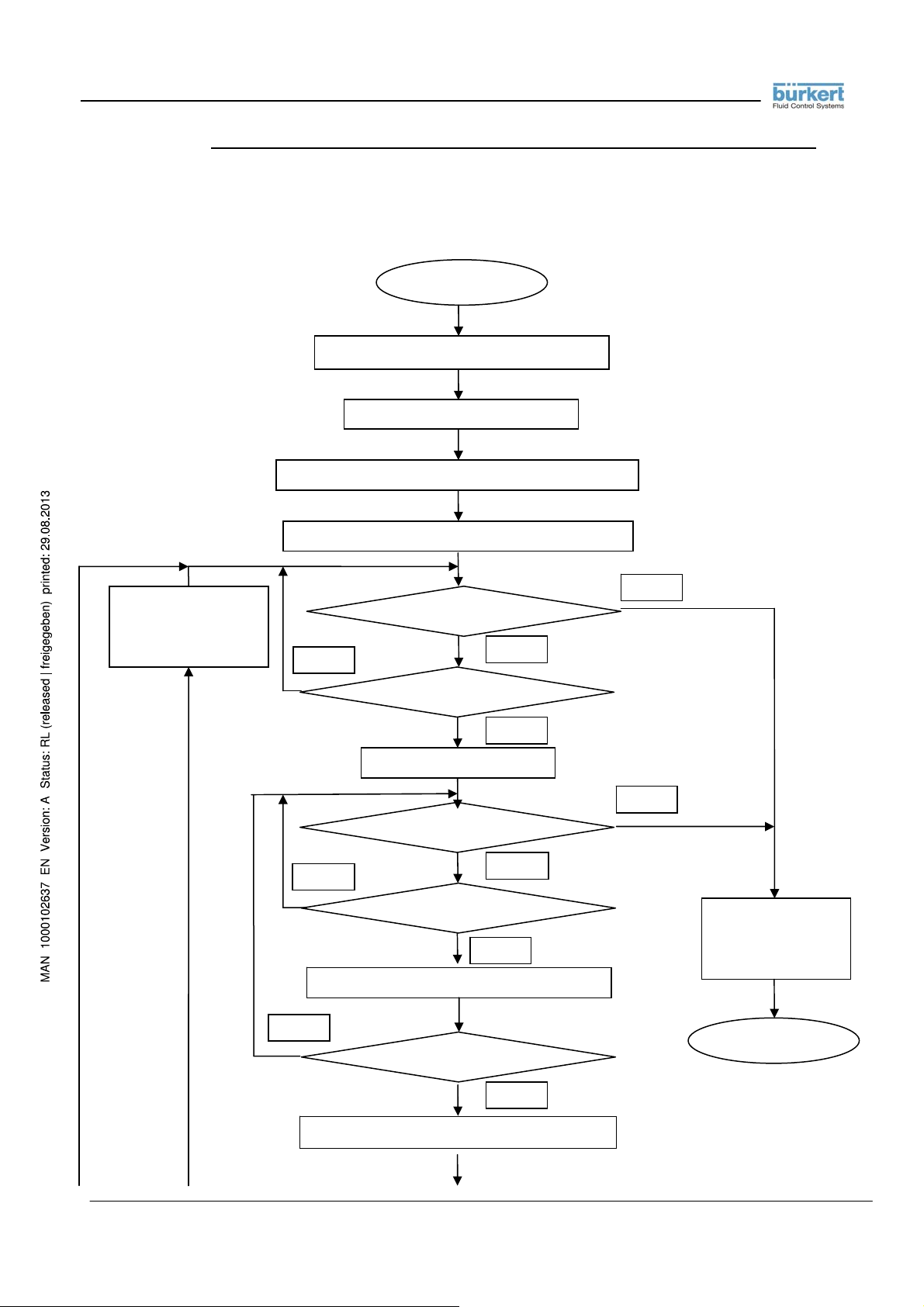
3.3.13. FLOW CHART FOR SENDING ETP COMMAND AND RECEPTION OF THE ANSWER
Flow chart with description of the sending of an ETP command to a converter through the RS 485 port and wait cycle
for the reception of the answer
The MASTER generates ETP command
The MASTER enables the transmitter
The MASTER send ETP command to the addressed SLAVE
The MASTER enable receiver - Start timer T
Packet with addresses
for other device
Packet deleted
T
Reset timer
lim
No
No
No
The MASTER decode the Header answer
START
Timer T
Has it received char ?
Start timer char
Timer char expired ?
Has it received char ?
Reset timer cha r
Has received 4 bytes ?
expired ?
lim
No
Si
No
Si
Si
Si
Si
The Timer has expired
Answer not received
END
- 28 - RS232_485_ETP_MODBUS_BU_REV02.doc
Page 29
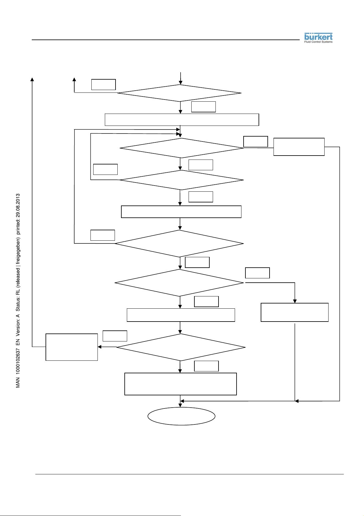
Another block to
receive
Note:
The timer char is set to 2.5 time the time necessary for to receive a char: 2.5 * tchar.
Every time there is a char in the receive buffer the timer char is restart.
If the receive buffer doesn’t receive a char in the next 2.5 * tchar, the timer char expire and the reception of data is
terminated.
- 29 - RS232_485_ETP_MODBUS_BU_REV02.doc
No
The address are ok ?
Si
The MASTER read the BLOCK CODE and BLOCK LENGHT
Timer char expired ?
No
Has it received char ?
Reset timer cha r
No
Has the MASTER received
BLOCK LENGHT chars ?
The checksum is ok ?
Decoding of the answer with success
No
Is the Block code = 0xDA ?
Is this the last block
Block code = 0xDA
This is the last block
Reception completed
No
Si
Si
Si
Si
END
Si
No
Packet not
complete
Bad Checksum
Packet corrupted
Page 30

3.3.14. LIST OF SUPPORTED COMMANDS GROUPED SIMILARLY TO THE INTERNAL MENU
SYSTEM
NOTE ( VALID FOR ALL FUNCTIONS ) : returned value 5 = ACCESS ERR ( insufficient access
level )
COMMANDS AND FUNCTIONS EQUIVALENT TO THE “1-SENSOR” MENU
Name and description Modes Returned values or codes
PDIMV (Pipe DIaMeter Value)
Reads or sets the nominal diameter
of the sensor.
CFFKA (CoeFFicient KA) Reads or
sets the value of the gain coefficient
KA
SMODL (Sensor MODeL) Reads or
sets the value of the sensor model
SIPOS (Sensor Insertion POSition)
Reads or sets the value that
identifies the insertion position for
that type of sensor
CKLP0, CKLP1, CKLP2, CKLP3,
CKLP4, CKLP5 (Coefficient KL
Positive 0, 1, 2, 3, 4 an 5) Reads
- 30 - RS232_485_ETP_MODBUS_BU_REV02.doc
Read command: PDIMV?
Set command: PDIMV=
Help command: PDIMV=?
Read command: CFFKA?
Set command: CFFKA=
Help command: CFFKA=?
Read command: SMODL?
Set command: SMODL=
Help command: SMODL=?
Read command: SIPOS?
Set command: SIPOS=
Help command: SIPOS=?
Read command: CKLP0?
value of nominal diameter if accepted
5:ACCESS ERR if insufficient access
level
0:OK if parameters accepted
n
2:PARAM ERR if
5:ACCESS ERR if insufficient access
level
min <> max (unit)
5:ACCESS ERR if insufficient access
level
Value of the coefficient if accepted
5:ACCESS ERR if insufficient access
level
0:OK if parameters accepted
n
2:PARAM ERR if
5:ACCESS ERR if insufficient access
level
min <> max
5:ACCESS ERR if insufficient access
level
Value of the sensor model if accepted
5:ACCESS ERR if insufficient access
level
5:ACCESS ERR if insufficient access
level
0:OK if parameters accepted
n
2:PARAM ERR if
5:ACCESS ERR if insufficient access
level
min <> max
5:ACCESS ERR if insufficient access
level
Value of the insertion position if
accepted
5:ACCESS ERR if insufficient access
level
n
0:OK if parameters accepted
2:PARAM ERR if
5:ACCESS ERR if insufficient access
level
min <> max
5:ACCESS ERR if insufficient access
level
Value of the coefficient if accepted
5:ACCESS ERR if insufficient access
level
n
out of range
if accepted
n
out of range
if accepted
n
out of range
if accepted
n
out of range
if accepted
Page 31

or sets the value for the six
coefficients for the linearization of
the positive flow rate range.
NOTE: the examples refer to the
command CKLP0, but the others
are the same
CKLN0, CKLN1, CKLN2, CKLN3,
CKLN4, CKLN5 (Coefficient KL
Negative 0, 1, 2, 3, 4 an 5) Reads
or sets the value for the six
coefficients for the linearization of
the negative flow rate range.
NOTE: the examples refer to the
command CKLN0, but the others
are the same
SFREQ (Sampling FREQuency)
Reads or sets the measure sampling
frequency of the instrument.
CRVRF (Coil Regulator Voltage
ReFerence) Reads or sets the value
of the reference for the coil current
regulator.
Set command: CKLP0=
Help command: CKLP0=?
Read command: CKLN0?
Set command: CKLN0=
Help command: CKLN0=?
Read command: SFREQ?
Read command: CRVRF?
Help command: CRVRF=?
n
n
0:OK if parameters accepted
2:PARAM ERR if
5:ACCESS ERR if insufficient access
level
min <> max
5:ACCESS ERR if insufficient access
level
Value of the coefficient if accepted
5:ACCESS ERR if insufficient access
level
0:OK if parameters accepted
2:PARAM ERR if
5:ACCESS ERR if insufficient access
level
min <> max
5:ACCESS ERR if insufficient access
level
Value of the measure sampling
frequency
5:ACCESS ERR if insufficient access
level
Value of the coil regulator voltage
reference
5:ACCESS ERR if insufficient access
level
min <> max
5:ACCESS ERR if insufficient access
level
n
out of range
if accepted
n
out of range
if accepted
if accepted
CRRMA (Coil Regulator Regulation
MArgin) Reads or sets the value of
the regulation margin for the coil
current regulator.
EPDEN (Empty Pipe Detection
ENable) Enables or disables the
empty pipe detection circuit.
EPDGV (Empty Pipe Detection
Gain Value) Reads or sets the value
of the gain for the empty pipe
detection circuit.
Read command: CRRMA?
Help command: CRRMA=?
Read command: EPDEN?
Set command: EPDEN=
Help command: EPDEN=? 0:OFF,1:ON if accepted
Read command: EPDGV?
Help command: EPDGV=?
Value of the coil regulator margin
5:ACCESS ERR if insufficient access
level
min <> max
5:ACCESS ERR if insufficient access
level
State of the pipe detection circuit
5:ACCESS ERR if insufficient access
level
n
0:OK if parameters accepted
2:PARAM ERR if
5:ACCESS ERR if insufficient access
level
5:ACCESS ERR if insufficient access
level
Value of the empty pipe detection gain
5:ACCESS ERR if insufficient access
level
min <> max
5:ACCESS ERR if insufficient access
level
if accepted
n
out of range
if accepted
- 31 - RS232_485_ETP_MODBUS_BU_REV02.doc
Page 32

EPDCC (Empty Pipe Detection
Calibration Command) Executes the
calibration of the empty pipe
detection circuit.
SZPCC (Sensor Zero Point
Calibration Command) Executes the
calibration of the sensor zero point.
SZPCR (Sensor Zero Point
Calibration Reset) Resets the zero
point calibration value evaluated
with the preceding instruction
SZPCC.
COMMANDS AND FUNCTIONS EQUIVALENT TO THE “2-SCALES” MENU
Name and description Modes Returned values or codes
FRMUT (Flow Rate Measure Unit
Type) Reads or sets the type of
measure units relative to the flow
rate. Possible values are:
0:VM = Volume, Metric
1:WM = Weight, Metric
2:VI = Volume, Imperial or American
3:WI = Weight, Imperial or American
FRMUV (Flow Rate Measure Unit
Value) Reads or sets the value of
measure units relative to the flow
rate.
- 32 - RS232_485_ETP_MODBUS_BU_REV02.doc
Read command: NOT
SUPPORTED
Set command: EPDCC=1
Help command: EPDCC=? 1:EXECUTE
Read command: SZPCC? 0 if the calibration is terminated
Set command: SZPCC=1
Help command: SZPCC=? 1:EXECUTE if accepted
Read command: NOT
SUPPORTED
Set command: SZPCR=1
Help command: SZPCR=? 1:EXECUTE
Read command: FRMUT?
Set command: FRMUT=
Help command: FRMUT=?
Read command: FRMUV?
Set command: FRMUV=
Help command: FRMUV=?
1:CMD ERR if read command is
issued
5:ACCESS ERR if insufficient access
level
0:OK if execution ok
2:PARAM ERR if parameter not equal
to 1
if accepted
1 if the calibration is in progress
5:ACCESS ERR if insufficient access
level
0:OK if execution ok
2:PARAM ERR if parameter not equal
to 1
5:ACCESS ERR if insufficient access
level
5:ACCESS ERR if insufficient access
level
1:CMD ERR if read command is
issued
5:ACCESS ERR if insufficient access
level
0:OK if execution ok
2:PARAM ERR if parameter not equal
to 1
5:ACCESS ERR if insufficient access
level
if accepted
5:ACCESS ERR if insufficient access
level
Value of measure unit if accepted
5:ACCESS ERR if insufficient access
level
0:OK if parameters accepted
n
n
2:PARAM ERR if
5:ACCESS ERR if insufficient access
level
num:description
List of
5:ACCESS ERR if insufficient access
level
Value of measure unit if accepted
5:ACCESS ERR if insufficient access
level
0:OK if parameters accepted
2:PARAM ERR if
5:ACCESS ERR if insufficient access
level
num:description
List of
5:ACCESS ERR if insufficient access
level
n
out of range
if accepted
n
out of range
if accepted
Page 33

FRFS1 (Flow Rate Full Scale 1)
Reads or sets the value of flow rate
full scale 1.
FRFS2 (Flow Rate Full Scale 2)
Reads or sets the value of flow rate
full scale 2.
VTMUT (Volume Totalizer Measure
Unit Type) Reads or sets the type of
measure units relative to the
totalizers. Possible values are:
0:VM = Volume, Metric
1:WM = Weight, Metric
2:VI = Volume, Imperial or American
3:WI = Weight, Imperial or American
VTMUV (Volume Totalizer Measure
Unit Value) Reads or sets the value of
measure units relative to the
totalizers.
VTDPP (Volume Totalizers Decimal
Point Position) Reads or sets the
value representing the number of
decimal digits for representing the
volume totalizers.
Read command: FRFS1?
Set command: FRFS1=
Help command: FRFS1=?
Read command: FRFS2?
Set command: FRFS2=
Help command: FRFS2=?
Read command: VTMUT?
Set command: VTMUT=
Help command: VTMUT=?
Read command: VTMUV?
Set command: VTMUV=
Help command: VTMUV=?
Read command: VTDPP?
Set command: VTDPP=
Help command: VTDPP=?
n
n
n
n
n
Value of flow rate full scale 1 if accepted
5:ACCESS ERR if insufficient access
level
0:OK if parameters accepted
2:PARAM ERR if
5:ACCESS ERR if insufficient access
level
min <> max (units)
5:ACCESS ERR if insufficient access
level
Value of flow rate full scale 2 if accepted
1:CMD ERR if full scale 2 not enabled
5:ACCESS ERR if insufficient access
level
0:OK if parameters accepted
1:CMD ERR if full scale 2 not enabled
2:PARAM ERR if
5:ACCESS ERR if insufficient access
level
min <> max (units)
1:CMD ERR if full scale 2 not enabled
5:ACCESS ERR if insufficient access
level
Type of measure unit if accepted
5:ACCESS ERR if insufficient access
level
0:OK if parameters accepted
2:PARAM ERR if
5:ACCESS ERR if insufficient access
level
num:description
List of
5:ACCESS ERR if insufficient access
level
Value of measure unit if accepted
5:ACCESS ERR if insufficient access
level
0:OK if parameters accepted
2:PARAM ERR if
5:ACCESS ERR if insufficient access
level
List of
num:description
5:ACCESS ERR if insufficient access
level
Value of decimal digits if accepted
5:ACCESS ERR if insufficient access
level
0:OK if parameters accepted
2:PARAM ERR if
5:ACCESS ERR if insufficient access
level
min <> max
5:ACCESS ERR if insufficient access
level
n
out of range
if accepted
n
out of range
if accepted
n
out of range
n
out of rang
n
out of range
if accepted
if accepted
if accepted
- 33 - RS232_485_ETP_MODBUS_BU_REV02.doc
Page 34

CH1PV (CHannel 1 Pulse Value)
Reads or sets the value representing
the volume of one totalization pulse
for the channel 1.
CH2PV (CHannel 2 Pulse Value)
Reads or sets the value representing
the volume of one totalization pulse
for the channel 2.
CH1PT (CHannel 1 Pulse Time)
Reads or sets the value representing
the time duration pulse for the
channel 1.
CH2PT (CHannel 2 Pulse Time)
Reads or sets the value representing
the time duration pulse for the
channel 2.
VMSGC (Volume to Mass Specific
Gravity Coefficient) Reads or sets the
value representing the transformation
coefficient between volume and mass.
- 34 - RS232_485_ETP_MODBUS_BU_REV02.doc
Read command: CH1PV?
Set command: CH1PV=
Help command: CH1PV=?
Read command: CH2PV?
Set command: CH2PV=
Help command: CH2PV=?
Read command: CH1PT?
Set command: CH1PT=
Help command: CH1PT=?
Read command: CH2PT?
Set command: CH2PT=
Help command: CH2PT =?
Read command: VMSGK?
n
n
n
n
Value of volume pulse for channel 1
1:CMD ERR if channel 1 not enabled
5:ACCESS ERR if insufficient access
level
0:OK if parameters accepted
1:CMD ERR if channel 1 not enabled
n
2:PARAM ERR if
5:ACCESS ERR if insufficient access
level
min <> max (units)
1:CMD ERR if channel 1 not enabled
5:ACCESS ERR if insufficient access
level
Value of volume pulse for channel 2
1:CMD ERR if channel 2 not enabled
5:ACCESS ERR if insufficient access
level
0:OK if parameters accepted
1:CMD ERR if channel 2 not enabled
2:PARAM ERR if
5:ACCESS ERR if insufficient access
level
min <> max (units)
1:CMD ERR if channel 2 not enabled
5:ACCESS ERR if insufficient access
level
Value of pulse time for channel 1
1:CMD ERR if channel 1 not enabled
5:ACCESS ERR if insufficient access
level
0:OK if parameters accepted
1:CMD ERR if channel 1 not enabled
2:PARAM ERR if
5:ACCESS ERR if insufficient access
level
min <> max (units)
1:CMD ERR if channel 1 not enabled
5:ACCESS ERR if insufficient access
level
Value of pulse time for channel 2
1:CMD ERR if channel 2 not enabled
5:ACCESS ERR if insufficient access
level
0:OK if parameters accepted
1:CMD ERR if channel 2 not enabled
2:PARAM ERR if
5:ACCESS ERR if insufficient access
level
min <> max (units)
1:CMD ERR if channel 2 not enabled
5:ACCESS ERR if insufficient access
level
Value of volume-to-mass coefficient
1:CMD ERR if weight units not enabled
5:ACCESS ERR if insufficient access
level
out of range
if accepted
n
out of range
if accepted
n
out of range
if accepted
n
out of range
if accepted
Page 35

0:OK if parameters accepted
1:CMD ERR if weight units not enabled
n
2:PARAM ERR if
5:ACCESS ERR if insufficient access
level
min <> max (units)
1:CMD ERR if weight units not enabled
5:ACCESS ERR if insufficient access
level
Value of analog input 1 measure unit
symbol
1:CMD ERR if analog input 1 not
enabled
5:ACCESS ERR if insufficient access
level
0:OK if parameters accepted
1:CMD ERR if analog input 1 not
enabled
2:PARAM ERR if
chars
5:ACCESS ERR if insufficient access
level
3 CHR STRING
1:CMD ERR if analog input 1 not
enabled
5:ACCESS ERR if insufficient access
level
Value of measure unit if accepted
1:CMD ERR if analog input 1 not
enabled
5:ACCESS ERR if insufficient access
level
0:OK if parameters accepted
1:CMD ERR if analog input 1 not
n
enabled
2:PARAM ERR if
5:ACCESS ERR if insufficient access
level
num:description
List of
1:CMD ERR if analog input 1 not
enabled
5:ACCESS ERR if insufficient access
level
Start scale value of analog in.1 if
accepted
1:CMD ERR if analog input 1 not
enabled
5:ACCESS ERR if insufficient access
level
0:OK if parameters accepted
1:CMD ERR if analog input 1 not
enabled
2:PARAM ERR if
5:ACCESS ERR if insufficient access
level
n
out of range
if accepted
string
length is not 3
if accepted
n
out of range
if accepted
n
out of range
A1CSY (Analog input 1 Custom
SYmbol) Reads or sets the value
representing the custom measure unit
used for the analog input 1. If the
values is to be set, a fixed 3characters length string must be
supplied.
A1MUV (Analog input 1 Measure
Unit Value) Reads or sets the value of
measure units relative to the
totalizers.
A1SSV (Analog input 1 Start Scale
Value) Reads or sets the value of the
start scale point for the analog input
1.
Set command: VMSGK=
Help command: VMSGK=?
Read command: A1CSY?
Set command: 1CSY=
Help command: A1CSY=?
Read command: A1MUV?
Set command: A1MUV=
Help command: A1MUV=?
Read command: A1SSV?
Set command: A1SSV=
string
n
- 35 - RS232_485_ETP_MODBUS_BU_REV02.doc
Page 36

A1FSV (Analog input 1 Full Scale
Value) Reads or sets the value of the
full scale point for the analog input 1.
COMMANDS AND FUNCTIONS EQUIVALENT TO THE “3-MEASURES” MENU
Name and description Modes Returned values or codes
MFTCV (Measure Filter Time
Constant Value) Reads or sets the
value of the measure filter time
constant.
MFSKT (Measure Filter SKip
Threshold) Reads or sets the value
of the measure filter skip
threshold.
MFMXT (Measure Filter MaX
variation Threshold) Reads or sets
the value of the measure filter
maximum variation threshold.
Help command: A1SSV=?
Read command: A1FSV?
Set command: A1FSV=
Help command: A1FSV=?
Read command: MFTCV?
Set command: MFTCV=
Help command: MFTCV=?
Read command: MFSKT?
Set command: MFSKT=
Help command: MFSKT=?
Read command: MFMXT?
Set command: MFMXT=
n
n
n
min <> max (units)
1:CMD ERR if analog input 1 not
enabled
5:ACCESS ERR if insufficient access
level
Full scale value of analog in.1 if
accepted
1:CMD ERR if analog input 1 not
enabled
5:ACCESS ERR if insufficient access
level
0:OK if parameters accepted
1:CMD ERR if analog input 1 not
n
enabled
2:PARAM ERR if
5:ACCESS ERR if insufficient access
level
min <> max (units)
1:CMD ERR if analog input 1 not
enabled
5:ACCESS ERR if insufficient access
level
Value of measure time constant if
accepted
5:ACCESS ERR if insufficient access
level
0:OK if parameters accepted
2:PARAM ERR if
5:ACCESS ERR if insufficient access
level
n
out of range
min <> max (units)
5:ACCESS ERR if insufficient access
level
Value of measure skip threshold if
accepted
5:ACCESS ERR if insufficient access
level
0:OK if parameters accepted
2:PARAM ERR if
5:ACCESS ERR if insufficient access
level
n
out of range
min <> max (units)
5:ACCESS ERR if insufficient access
level
Value of max. variation threshold if
accepted
5:ACCESS ERR if insufficient access
level
0:OK if parameters accepted
2:PARAM ERR if
5:ACCESS ERR if insufficient access
level
n
out of range
if accepted
n
out of range
if accepted
if accepted
if accepted
- 36 - RS232_485_ETP_MODBUS_BU_REV02.doc
Page 37

Help command: MFMXT=?
MFCUT (Measure Filter Cut-off
Threshold) Reads or sets the value
of the measure filter cut-off
threshold.
ACALE (Auto-CALibration Enable)
Enables or disables the autocalibration feature of the
instrument.
ARNGE (Auto-RaNGe Enable)
Enables or disables the auto-range
feature of the instrument.
ENSVE (ENergy-SaVing Enable)
Enables or disables the energysaving feature of the instrument.
ENSST (ENergy-Saving Sample
Time) Reads or sets the value of
the measure sampling time when
the energy-saving feature is active.
- 37 - RS232_485_ETP_MODBUS_BU_REV02.doc
Read command: MFCUT?
Set command: MFCUT=
Help command: MFCUT=?
Read command: ACAL E?
Set command: ACALE=
Help command: ACALE=? List of
Read command: ARNG E?
Set command: ARNGE=
Help command: ARNGE=? List of
Read command: ENSVE?
Set command: ENSVE=
Help command: ENSVE=? List of
Read command: ENSST?
Set command: ENSST=
Help command: ENSST=?
min <> max (units)
5:ACCESS ERR if insufficient access
level
Value of measure cut-off thr. if
accepted
5:ACCESS ERR if insufficient access
level
0:OK if parameters accepted
n
2:PARAM ERR if
5:ACCESS ERR if insufficient access
level
min <> max (units)
5:ACCESS ERR if insufficient access
level
Enable/disable status if accepted
5:ACCESS ERR if insufficient access
level
n
0:OK if parameters accepted
2:PARAM ERR if
5:ACCESS ERR if insufficient access
level
num:description
5:ACCESS ERR if insufficient access
level
Enable/disable status if accepted
5:ACCESS ERR if insufficient access
level
n
0:OK if parameters accepted
2:PARAM ERR if
5:ACCESS ERR if insufficient access
level
num:description
5:ACCESS ERR if insufficient access
level
Enable/disable status if accepted
5:ACCESS ERR if insufficient access
level
0:OK if parameters accepted
n
2:PARAM ERR if
5:ACCESS ERR if insufficient access
level
num:description
5:ACCESS ERR if insufficient access
level
Value of measure sampling time if
accepted
5:ACCESS ERR if insufficient access
level
n
0:OK if parameters accepted
2:PARAM ERR if
5:ACCESS ERR if insufficient access
level
min <> max (units)
5:ACCESS ERR if insufficient access
level
if accepted
n
out of range
if accepted
n
out of range
if accepted
n
out of range
if accepted
n
out of range
if accepted
n
out of range
if accepted
Page 38

COMMANDS AND FUNCTIONS EQUIVALENT TO THE “4-ALARMS” MENU
Name and description Modes Returned values or codes
FRAXP (Flow Rate Alarm maX
Positive threshold) Reads or sets
the value of the maximum positive
flow rate alarm threshold.
FRAXN (Flow Rate Alarm maX
Negative threshold) Reads or sets
the value of the maximum positive
flow rate alarm threshold.
FRANP (Flow Rate Alarm miN
Positive threshold) Reads or sets
the value of the minimum positive
flow rate alarm threshold.
FRANN (Flow Rate Alarm miN
Negative threshold) Reads or sets
the value of the minimum positive
flow rate alarm threshold.
ATHYS (Alarm Thresholds
HYSteresis) Reads or sets the value
of the alarm threshold hysteresis.
- 38 - RS232_485_ETP_MODBUS_BU_REV02.doc
Read command: FRAXP?
Set command: FRAXP=
Help command: FRAXP=?
Read command: FRAXN?
Set command: FRAXN=
Help command: FRAXN=?
Read command: FRANP?
Set command: FRAXP=
Help command: FRAXP=?
Read command: FRANN?
Set command: FRANN=
Help command: FRANN=?
Read command: ATHYS? Value of hysteresis if accepted
Set command: ATHYS=
Help command: ATHYS=?
Value of positive max threshold if
accepted
5:ACCESS ERR if insufficient access
level
n
0:OK if parameters accepted
2:PARAM ERR if
5:ACCESS ERR if insufficient access
level
min <> max (units)
5:ACCESS ERR if insufficient access
level
Value of negative max threshold if
accepted
5:ACCESS ERR if insufficient access
level
n
0:OK if parameters accepted
2:PARAM ERR if
5:ACCESS ERR if insufficient access
level
min <> max (units)
5:ACCESS ERR if insufficient access
level
Value of positive min threshold if
accepted
5:ACCESS ERR if insufficient access
level
n
0:OK if parameters accepted
2:PARAM ERR if
5:ACCESS ERR if insufficient access
level
min <> max (units)
5:ACCESS ERR if insufficient access
level
Value of negative min threshold if
accepted
5:ACCESS ERR if insufficient access
level
n
0:OK if parameters accepted
2:PARAM ERR if
5:ACCESS ERR if insufficient access
level
min <> max (units)
5:ACCESS ERR if insufficient access
level
5:ACCESS ERR if insufficient access
level
n
0:OK if parameters accepted
2:PARAM ERR if
5:ACCESS ERR if insufficient access
level
min <> max (units)
5:ACCESS ERR if insufficient access
level
n
out of range
if accepted
n
out of range
if accepted
n
out of range
if accepted
n
out of range
if accepted
n
out of range
if accepted
Page 39

EPDAT (Empty Pipe Detection
Alarm Threshold) Reads or sets the
value of the alarm threshold for the
empty pipe detection system.
OCACV (Output Current Alarm
Condition Value) Reads or sets the
value of the alarm value at which
the current output will be set in
case of error conditions. Valid only if
the current output is installed and
enabled.
COMMANDS AND FUNCTIONS EQUIVALENT TO THE “5-INPUTS” MENU
Name and description Modes Returned values or codes
VTTPE (Volume Totalizer Total
Positive reset Enable) Enables or
disables the consent for resetting
the total positive volume totalizer
when receiving an external signal
on the digital input. Valid only if
the digital input is installed and
enabled.
VTPPE (Volume Totalizer Partial
Positive reset Enable) Enables or
disables the consent for resetting
the partial positive volume totalizer
when receiving an external signal
Read command: EPDAT?
Set command: EPDAT=
Help command: EPDAT=?
Read command: OCACV?
Set command: OCACV=
Help command: OCACV=?
Read command: VTTPE?
Set command: VTTPE=
Help command: VTTPE=? List of
Read command: VTPPE?
Value of empty pipe threshold if
accepted
5:ACCESS ERR if insufficient access
level
0:OK if parameters accepted
n
2:PARAM ERR if
5:ACCESS ERR if insufficient access
level
min <> max (units)
5:ACCESS ERR if insufficient access
level
Value of alarm current output if
accepted
1:CMD ERR if current output not
enabled
5:ACCESS ERR if insufficient access
level
0:OK if parameters accepted
n
1:CMD ERR if current output not
enabled
2:PARAM ERR if
5:ACCESS ERR if insufficient access
level
min <> max (units)
1:CMD ERR if current output not
enabled .
5:ACCESS ERR if insufficient access
level
Status of reset consent if accepted
1:CMD ERR if digital input not
enabled
5:ACCESS ERR if insufficient access
level
0:OK if parameters accepted
n
1:CMD ERR if digital input not
enabled
2:PARAM ERR if
5:ACCESS ERR if insufficient access
level
1:CMD ERR if digital input not
enabled
5:ACCESS ERR if insufficient access
level
Status of reset consent if accepted
1:CMD ERR if digital input not
enabled
5:ACCESS ERR if insufficient access
level
n
out of range
if accepted
n
out of range
if accepted
n
out of range
num:description
if accepted
- 39 - RS232_485_ETP_MODBUS_BU_REV02.doc
Page 40

on the digital input. Valid only if
the digital input is installed and
enabled.
VTTNE (Volume Totalizer Total
Negative reset Enable) Enables or
disables the consent for resetting
the total negative volume totalizer
when receiving an external signal
on the digital input. Valid only if
the digital input is installed and
enabled.
VTPNE (Volume Totalizer Partial
Negative reset Enable) Enables or
disables the consent for resetting
the partial negative volume
totalizer when receiving an
external signal on the digital input.
Valid only if the digital input is
installed and enabled.
TCLIE (Totalizers Count Lock
Input Enable) Enables or disables
the consent for locking the
totalizers when receiving an
external signal on the digital input.
Valid only if the digital input is
installed and enabled.
Set command: VTPPE=
Help command: VTPPE=? List of
Read command: VTTNE?
Set command: VTTNE=
Help command: VTTNE=? List of
Read command: VTPNE?
Set command: VTPNE=
Help command: VTPNE=? List of
Read command: TCLIE?
Set command: TCLIE=
n
0:OK if parameters accepted
1:CMD ERR if digital input not
enabled
2:PARAM ERR if
5:ACCESS ERR if insufficient access
level
1:CMD ERR if digital input not
enabled
5:ACCESS ERR if insufficient access
level
Status of reset consent if accepted
1:CMD ERR if digital input not
enabled
5:ACCESS ERR if insufficient access
level
n
0:OK if parameters accepted
1:CMD ERR if digital input not
enabled
2:PARAM ERR if
5:ACCESS ERR if insufficient access
level
1:CMD ERR if digital input not
enabled
5:ACCESS ERR if insufficient access
level
Status of locking consent if accepted
1:CMD ERR if digital input not
enabled
5:ACCESS ERR if insufficient access
level
0:OK if parameters accepted
n
1:CMD ERR if digital input not
enabled
2:PARAM ERR if
5:ACCESS ERR if insufficient access
level
n
out of range
num:description
n
out of range
num:description
n
out of range
num:description
n
out of range
if accepted
if accepted
if accepted
- 40 - RS232_485_ETP_MODBUS_BU_REV02.doc
Page 41

Help command: TCLIE=? List of
num:description
if accepted
1:CMD ERR if digital input not
enabled
5:ACCESS ERR if insufficient access
level
CALIE (CALibration Input Enable)
Enables or disables the consent for
calibrating when receiving an
external signal on the digital input.
Valid only if the digital input is
installed and enabled.
Read command: CALIE?
Set command: CALIE=
Status of calibration consent if
accepted
1:CMD ERR if digital input not
enabled
0:OK if parameters accepted
n
1:CMD ERR if digital input not
enabled
n
2:PARAM ERR if
out of range
5:ACCESS ERR if insufficient access
level
Help command: CALIE=? List of
num:description
if accepted
1:CMD ERR if digital input not
enabled
5:ACCESS ERR if insufficient access
level
SRCIE (Scale Range Change
Input Enable) Enables or disables
the consent for changing the scale
range when receiving an external
signal on the digital input. Valid
only if the digital input is installed
and enabled.
Read command: SRCIE?
Set command: SRCIE=
Status of range change consent if
accepted
1:CMD ERR if digital input not
enabled
5:ACCESS ERR if insufficient access
level
0:OK if parameters accepted
n
1:CMD ERR if digital input not
enabled
n
2:PARAM ERR if
out of range
5:ACCESS ERR if insufficient access
level
Help command: SRCIE=? List of
num:description
if accepted
1:CMD ERR if digital input not
enabled
5:ACCESS ERR if insufficient access
level
WKUIE (WaKe-Up Input Enable)
Enables or disables the consent for
waking-up from the energy saving
standby mode when receiving an
external signal on the digital input.
Valid only if the digital input is
installed and enabled.
Read command: WKUIE?
Set command: WKUIE =
Status of wake-up consent if accepted
1:CMD ERR if digital input not
enabled
5:ACCESS ERR if insufficient access
level
0:OK if parameters accepted
n
1:CMD ERR if digital input not
enabled
n
2:PARAM ERR if
out of range
5:ACCESS ERR if insufficient access
level
Help command: WKUIE
=?
num:description
List of
1:CMD ERR if digital input not
enabled
if accepted
5:ACCESS ERR if insufficient access
level
COMMANDS AND FUNCTIONS EQUIVALENT TO THE “6-OUTPUTS” MENU
- 41 - RS232_485_ETP_MODBUS_BU_REV02.doc
Page 42

Name and description Modes Returned values or codes
OUT1F (OUTput 1 Function) Sets
the function type related to the
digital output 1. Valid only if the
digital outputs are installed and
enabled.
OUT2F (OUTput 2 Function) Sets
the function type related to the
digital output 2. Valid only if the
digital outputs are installed and
enabled.
OUTIS (OUT Immediate State)
function for set in direct way the
value of the digital outputs
CO1FS (Current Output 1 Full
Scale) Sets the full scale value for
the current output 1: it can be 20
or 22 mA. Valid only if the current
output1 is installed and enabled.
Read command: OUT1F?
Set command: OUT1F=
Help command: OUT1F=? List of
Read command: OUT2F?
Set command: OUT2F=
Help command: OUT2F=? List of
Read command: OUTI S?
Set command: OUTIS=
Help command: OUTIS=? List of
Read command: CO1FS?
Type of function if accepted
1:CMD ERR if digital outputs not
enabled
5:ACCESS ERR if insufficient access
level
n
0:OK if parameters accepted
1:CMD ERR if digital outputs not
enabled
n
2:PARAM ERR if
5:ACCESS ERR if insufficient access
level
num:description
1:CMD ERR if digital outputs not
enabled
5:ACCESS ERR if insufficient access
level
Type of function if accepted
1:CMD ERR if digital outputs not
enabled
5:ACCESS ERR if insufficient access
level
0:OK if parameters accepted
n
1:CMD ERR if digital outputs not
enabled
2:PARAM ERR if
5:ACCESS ERR if insufficient access
level
num:description
1:CMD ERR if digital outputs not
enabled
5:ACCESS ERR if insufficient access
level
Full scale value if accepted
1:CMD ERR if current output not
enabled
5:ACCESS ERR if insufficient access
level
out of range
if accepted
n
out of range
if accepted
n
out of range
if accepted
- 42 - RS232_485_ETP_MODBUS_BU_REV02.doc
Page 43

Set command: CO1FS=
Help command: CO1FS=? List of
CO1SS (Current Output 1 Start
Scale) Sets the start scale value
for the current output 1: it can be
0 or 4 mA. Valid only if the current
output1 is installed and enabled.
CO1FM (Current Output 1 Field
Mode) Sets the field mode value
for the current output 1: it can be
+, -, +/-, –0+. Valid only if the
current output1 is installed and
enabled.
COMMANDS AND FUNCTIONS EQUIVALENT TO THE “7-COMMUNICATION” MENU
Name and description Modes Returned values or codes
IF2PT (IF2 Protocol Type) Reads
or sets the protocol type for the
IF2 port: it can be DPP or HTP.
- 43 - RS232_485_ETP_MODBUS_BU_REV02.doc
Read command: CO1SS?
Set command: CO1SS=
Help command: CO1SS=? List of
Read command: CO1FM?
Set command: CO1FM=
Help command: CO1FM=? List of
Read command: IF2PT?
Set command: IF2PT=
n
0:OK if parameters accepted
1:CMD ERR if current output not
enabled
n
2:PARAM ERR if
5:ACCESS ERR if insufficient access
level
out of range
num:description
1:CMD ERR if current output not
enabled
5:ACCESS ERR if insufficient access
level
Start scale value if accepted
1:CMD ERR if current output not
enabled
5:ACCESS ERR if insufficient access
level
n
0:OK if parameters accepted
1:CMD ERR if current output not
enabled
n
2:PARAM ERR if
5:ACCESS ERR if insufficient access
level
out of range
num:description
1:CMD ERR if current output not
enabled
5:ACCESS ERR if insufficient access
level
Field mode for current output 1 if
accepted
1:CMD ERR if current output not
enabled
0:OK if parameters accepted
n
1:CMD ERR if current output not
enabled
n
2:PARAM ERR if
5:ACCESS ERR if insufficient access
level
out of range
num:description
1:CMD ERR if current output not
enabled
5:ACCESS ERR if insufficient access
level
Type of protocol if accepted
5:ACCESS ERR if insufficient access
level
0:OK if parameters accepted
n
2:PARAM ERR if
5:ACCESS ERR if insufficient access
level
n
out of range
if accepted
if accepted
if accepted
Page 44

DVADR (DeVice ADdRess) Reads
or sets the device address. Valid
only if the RS232 port is installed
and enabled.
232SP (rs232 SPeed) Reads or
sets the RS232 speed in bps. Valid
only if the RS232 port is installed
and enabled.
232PT (rs232 Protocol Type)
Reads or sets the protocol type for
the RS232 port: it can be DPP or
HTP. Valid only if the RS232 port is
installed and enabled.
SEVSE (Sms Event Send Enable)
Enable or disable event send by
SMS
SPDSE (Sms Process Data Send
Enable) Enable or disable process
data send by SMS
Help command: IF2PT=? List of
5:ACCESS ERR if insufficient access
level
Read command: DVADR?
Set command: DVADR=
Help command: DVADR=?
Read command: 232SP?
Set command: 232SP=
Help command: 232SP=? List of
Read command: 232PT?
Set command: 232PT=
Help command: 232PT=? List of
Read command: SEVSE?
Set command: SEVSE =
Help command: SEVSE =? List of
Read command: SPDSE?
Device address if accepted
1:CMD ERR if RS232 port not enabled
5:ACCESS ERR if insufficient access
level
0:OK if parameters accepted
n
1:CMD ERR if RS232 port not enabled
2:PARAM ERR if
5:ACCESS ERR if insufficient access
level
min <> max
1:CMD ERR if RS232 port not enabled
5:ACCESS ERR if insufficient access
level
RS232 speed if accepted
1:CMD ERR if RS232 port not enabled
5:ACCESS ERR if insufficient access
level
0:OK if parameters accepted
n
1:CMD ERR if RS232 port not enabled
2:PARAM ERR if
5:ACCESS ERR if insufficient access
level
1:CMD ERR if RS232 port not enabled
5:ACCESS ERR if insufficient access
level
RS232 protocol type if accepted
1:CMD ERR if RS232 port not enabled
5:ACCESS ERR if insufficient access
level
0:OK if parameters accepted
n
1:CMD ERR if RS232 port not enabled
2:PARAM ERR if
5:ACCESS ERR if insufficient access
level
1:CMD ERR if RS232 port not enabled
5:ACCESS ERR if insufficient access
level
Status of functions if accepted
5:ACCESS ERR if insufficient access
level
0:OK if parameters accepted
n
2:PARAM ERR if
5:ACCESS ERR if insufficient access
level
5:ACCESS ERR if insufficient access
level
Status of functions if accepted
5:ACCESS ERR if insufficient access
level
num:description
n
out of range
if accepted
n
out of range
num:description
n
out of range
num:description
n
out of range
num:description
if accepted
if accepted
if accepted
if accepted
- 44 - RS232_485_ETP_MODBUS_BU_REV02.doc
Page 45

SPDSC (Sms Process Data Send
Command) send a command for
immediately answer with process
data
ROAME (ROAMing Enable) Enable
or disable roaming function
SCAPE (SCADA Protocol Enable)
Enable or disable SCADA protocol
GSITM (Gsm Inactivity TiMeout)
timeout for inactivity connection
DTSDL (DaTa Send DeLay) delay
for send data
Set command: SPDSE =
Help command: SPDSE =? List of
Set command: SPDSC =
Help command: SPDSC =? List of
Read command: ROAME?
Set command: ROAME =
Help command: ROAME =? List of
Read command: SCAPE?
Set command: SCAPE =
Help command: SCAPE =? List of
Read command: GSITM?
Set command: GSITM =
Help command: GSITM =? Time range if accepted
Read command: DTSDL?
Set command: DTSDL =
Help command: DTSDL =? List of
n
0:OK if parameters accepted
2:PARAM ERR if
5:ACCESS ERR if insufficient access
level
n
out of range
num:description
5:ACCESS ERR if insufficient access
level
0:OK if command accepted
n
2:PARAM ERR if
5:ACCESS ERR if insufficient access
level
n
out of range
num:description
5:ACCESS ERR if insufficient access
level
Status of functions if accepted
5:ACCESS ERR if insufficient access
level
n
0:OK if parameters accepted
2:PARAM ERR if
5:ACCESS ERR if insufficient access
level
n
out of range
num:description
5:ACCESS ERR if insufficient access
level
Status of functions if accepted
5:ACCESS ERR if insufficient access
level
n
0:OK if parameters accepted
2:PARAM ERR if
5:ACCESS ERR if insufficient access
level
n
out of range
num:description
5:ACCESS ERR if insufficient access
level
Status of functions if accepted
5:ACCESS ERR if insufficient access
level
0:OK if parameters accepted
n
2:PARAM ERR if
5:ACCESS ERR if insufficient access
level
5:ACCESS ERR if insufficient access
level
Status of functions if accepted
5:ACCESS ERR if insufficient access
level
n
0:OK if parameters accepted
2:PARAM ERR if
5:ACCESS ERR if insufficient access
level
n
out of range
n
out of range
num:description
5:ACCESS ERR if insufficient access
level
if accepted
if accepted
if accepted
if accepted
if accepted
- 45 - RS232_485_ETP_MODBUS_BU_REV02.doc
Page 46

GSCLN (GSm CaLl Number)
telephone number for GSM
connection
485PT (RS485 Protocol Type)
Reads or sets the protocol type for
the RS485 port: it can be DPP, HTP
or MODBUS. Valid only if the RS485
port is installed and enabled
MODBP (MODBus Parity) parity
control in MODBUS protocol
COMMANDS AND FUNCTIONS EQUIVALENT TO THE “8-DISPLAY” MENU
Name and description Modes Returned values or codes
LLANG (Layout LANGuage)
Reads or sets the layout language
used for all the display messages.
VTTPR (Volume Totalizer Total
Positive Reset) Resets the total
positive volume totalizer.
Read command: GSCLN?
Set command: GSCLN =
Help command: GSCLN =? MAX 31 CHR STRING if accepted
Read command: 485PT?
Set command: 485PT =
Help command: 485PT =? List of
Read command: MODBP?
Set command: MODBP=
Help command: MODBP=? List of
Read command: LLANG?
Set command: LLANG=
Help command: LLANG=? List of
Read command: NOT
SUPPORTED
Set command: VTTPR=1
Status of functions if accepted
5:ACCESS ERR if insufficient access
level
n
0:OK if parameters accepted
2:PARAM ERR if
5:ACCESS ERR if insufficient access
level
5:ACCESS ERR if insufficient access
level
RS485 protocol type if accepted
1:CMD ERR if RS485 port not enabled
5:ACCESS ERR if insufficient access
level
n
0:OK if parameters accepted
1:CMD ERR if RS485 port not enabled
2:PARAM ERR if
5:ACCESS ERR if insufficient access
level
num:description
1:CMD ERR if RS485 port not enabled
5:ACCESS ERR if insufficient access
level
RS485 parity if accepted
5:ACCESS ERR if insufficient access
level
0:OK if parameters accepted
n
2:PARAM ERR if
5:ACCESS ERR if insufficient access
level
num:description
1:CMD ERR if RS232 port not enabled
5:ACCESS ERR if insufficient access
level
Layout language if accepted
5:ACCESS ERR if insufficient access
level
0:OK if parameters accepted
n
2:PARAM ERR if
5:ACCESS ERR if insufficient access
level
num:description
5:ACCESS ERR if insufficient access
level
1:CMD ERR if read command is
issued
5:ACCESS ERR if insufficient access
level
0:OK if parameters accepted
2:PARAM ERR if
5:ACCESS ERR if insufficient access
level
n
out of range
n
out of range
if accepted
n
out of range
if accepted
n
out of range
if accepted
n
not equal to 1
- 46 - RS232_485_ETP_MODBUS_BU_REV02.doc
Page 47

Help command: VTTPR=? 1:EXECUTE if accepted
5:ACCESS ERR if insufficient access
level
VTPPR (Volume Totalizer Partial
Positive Reset) Resets the partial
positive volume totalizer.
VTTNR (Volume Totalizer Total
Negative Reset) Resets the total
negative volume totalizer.
VTPNR (Volume Totalizer Partial
Negative Reset) Resets the partial
negative volume totalizer.
ENSDT (ENergy Saving Display
Time) Reads or sets the value of
the display on time used in the
energy saving mode. This time is
also used to wait for the incoming
of new sms if they are enabled.
QSTME (Quick STart Menu
Enable)
- 47 - RS232_485_ETP_MODBUS_BU_REV02.doc
Read command: NOT
SUPPORTED
Set command: VTPPR=1
Help command: VTPPR=? 1:EXECUTE
Read command: NOT
SUPPORTED
Set command: VTTNR=1
Help command: VTTNR=? 1:EXECUTE
Read command: NOT
SUPPORTED
Set command: VTPNR=1
Help command: VTPNR=? 1:EXECUTE
Read command: ENSDT?
Set command: ENSDT=
Help command: ENSDT=?
Read command: QSTME?
Set command: QSTME =
Help command: QSTME =? List of
1:CMD ERR if read command is
issued
5:ACCESS ERR if insufficient access
level
0:OK if parameters accepted
2:PARAM ERR if
5:ACCESS ERR if insufficient access
level
5:ACCESS ERR if insufficient access
level
1:CMD ERR if read command is
issued
5:ACCESS ERR if insufficient access
level
0:OK if parameters accepted
2:PARAM ERR if
5:ACCESS ERR if insufficient access
level
5:ACCESS ERR if insufficient access
level
1:CMD ERR if read command is
issued
5:ACCESS ERR if insufficient access
level
0:OK if parameters accepted
2:PARAM ERR if
5:ACCESS ERR if insufficient access
level
5:ACCESS ERR if insufficient access
level
Value of display on time if accepted
5:ACCESS ERR if insufficient access
level
0:OK if parameters accepted
n
2:PARAM ERR if
5:ACCESS ERR if insufficient access
level
min <> max (units)
5:ACCESS ERR if insufficient access
level
Status of functions if accepted
5:ACCESS ERR if insufficient access
level
n
0:OK if parameters accepted
2:PARAM ERR if
5:ACCESS ERR if insufficient access
level
num:description
5:ACCESS ERR if insufficient access
level
n
not equal to 1
if accepted
n
not equal to 1
if accepted
n
not equal to 1
if accepted
n
out of range
n
out of range
if accepted
if accepted
Page 48

TTNVE (TOTalizers Net Value
Enable) enable disable the
visualization of Net totalizer
TCMDE (Totalizers Currency Mode
Display Enable) Enables or
disables the displaying of the
currency values for the totalizers.
CUSYT (CUrrency SYmbol Type)
Reads or sets the type of currency
symbol used to represent the
values converted from the
totalizers.
CUCSS (CUrrency CuStom
Symbol) Reads or sets the custom
symbol used to represent the
currency. If the values is to be set,
a fixed 3-characters length string
must be supplied.
CUDEC (CUrrency DEcimal
Ciphers) Reads or sets the value of
the decimal ciphers for
representing the volume totalizers
Read command: TTNVE?
Set command: TTNVE =
Help command: TTNVE =? List of
Read command: TCMDE?
Set command: TCMDE=
Help command: TCMDE=? List of
Read command: CUSYT?
Set command: CUSYT=
Help command: CUSYT=? List of
Read command: CUCSS?
Set command:
CUCSS=
Help command: CUCSS=?
Read command: CUDEC?
string
Status of functions if accepted
5:ACCESS ERR if insufficient access
level
n
0:OK if parameters accepted
2:PARAM ERR if
5:ACCESS ERR if insufficient access
level
num:description
5:ACCESS ERR if insufficient access
level
Status of currency mode display if
accepted
5:ACCESS ERR if insufficient access
level
n
0:OK if parameters accepted
2:PARAM ERR if
5:ACCESS ERR if insufficient access
level
num:description
5:ACCESS ERR if insufficient access
level
Type of currency symbol if accepted
1:CMD ERR if currency not enable
5:ACCESS ERR if insufficient access
level
n
0:OK if parameters accepted
1:CMD ERR if currency not enabled
2:PARAM ERR if
5:ACCESS ERR if insufficient access
level
num:description
1:CMD ERR if currency not enabled
5:ACCESS ERR if insufficient access
level
Custom currency symbol if accepted
1:CMD ERR if currency not enabled
5:ACCESS ERR if insufficient access
level
0:OK if parameters accepted
1:CMD ERR if currency not enabled
2:PARAM ERR if
3 chars
5:ACCESS ERR if insufficient access
level
3 CHR STRING
1:CMD ERR if currency not enabled
5:ACCESS ERR if insufficient access
level
Value of decimal ciphers if accepted
1:CMD ERR if currency not enabled
5:ACCESS ERR if insufficient access
level
n
out of range
if accepted
n
out of range
if accepted
n
out of range
if accepted
string
length is not
if accepted
- 48 - RS232_485_ETP_MODBUS_BU_REV02.doc
Page 49

converted to currency.
CUPCF (CUrrency Positive
Conversion Factor) Reads or sets
the value of the conversion factor
coefficient used to convert the
partial positive totalizer to
currency.
CUNCF (CUrrency Negative
Conversion Factor) Reads or sets
the value of the conversion factor
coefficient used to convert the
partial negative totalizer to
currency.
COMMANDS AND FUNCTIONS EQUIVALENT TO THE “9-DATALOGGER” MENU
Name and description Modes Returned values or codes
DLOGE (Data LOGger Enable)
Enables or disables the logging
functions for data and events.
Events logging are always active.
Set command: CUDEC=
n
0:OK if parameters accepted
1:CMD ERR if currency not enabled
2:PARAM ERR if
5:ACCESS ERR if insufficient access
level
Help command: CUDEC=?
min <> max
1:CMD ERR if currency not enable
5:ACCESS ERR if insufficient access
level
Read command: CUPCF?
Value of positive conv. factor if
accepted
1:CMD ERR if currency not enabled
5:ACCESS ERR if insufficient access
level
Set command: CUPCF=
0:OK if parameters accepted
n
1:CMD ERR if currency not enabled
2:PARAM ERR if
5:ACCESS ERR if insufficient access
level
Help command: CUPCF=?
min <> max (units)
1:CMD ERR if currency not enable
5:ACCESS ERR if insufficient access
level
Read command: CUNCF?
Value of negative conv. factor if
accepted
1:CMD ERR if currency not enabled
5:ACCESS ERR if insufficient access
level
Set command: CUNCF=
0:OK if parameters accepted
n
1:CMD ERR if currency not enabled
2:PARAM ERR if
5:ACCESS ERR if insufficient access
level
Help command: CUNCF=?
min <> max (units)
1:CMD ERR if currency not enabled
5:ACCESS ERR if insufficient access
level
Read command: DLOGE?
Status of data logging functions if
accepted
5:ACCESS ERR if insufficient access
level
Set command: DLOGE=
0:OK if parameters accepted
n
2:PARAM ERR if
5:ACCESS ERR if insufficient access
level
Help command: DLOGE=? List of
5:ACCESS ERR if insufficient access
level
n
out of range
if accepted
n
out of range
if accepted
n
out of range
if accepted
n
out of range
num:description
if accepted
- 49 - RS232_485_ETP_MODBUS_BU_REV02.doc
Page 50

DLGSI (Data LoGger Sample
Interval) Reads or sets the sample
time interval at which the data are
collected.
DTIME (Date / TIME) Reads or
sets the date and time value.
WARNING: when setting the
date and time, always check
the value returned because
malformed input string may
lead to incorrect time result.
DLDRD (Data Logger static Data
ReaD) Reads the specified record,
the number of records saved in the
static data logger or the maximum
number of records that can be
saved in memory.
REset) Resets the static data logger
and clears all records.
Read command: DLGSI?
Set command: DLGSI=
Help command: DLGSI=? List of
Read command: DTIME?
Set command:
DTIME=
Help command: DTIME=?
Read number of records:
DLDRD?
Read record: DLDRD=
Read max. capacity:
DLDRD=?
Read command: NOT
SUPPORTED
Set command: DLDRE=1
tmstring
n
Value of sample time interval if
accepted
1:CMD ERR if logging functions not
enabled
5:ACCESS ERR if insufficient access
level
0:OK if parameters accepted
n
1:CMD ERR if logging functions not
enabled
2:PARAM ERR if
5:ACCESS ERR if insufficient access
level
num:description
1:CMD ERR if logging functions not
enabled
5:ACCESS ERR if insufficient access
level
Value of date and time if accepted
1:CMD ERR if logging functions not
enabled
5:ACCESS ERR if insufficient access
level
Value of current date and time
1:CMD ERR if logging functions not
enabled
5:ACCESS ERR if insufficient access
level
Format of the string to be input
1:CMD ERR if logging functions not
enabled
5:ACCESS ERR if insufficient access
level
Number of records in memory if
accepted
1:CMD ERR if logging functions not
enabled
Record n in CSV format if accepted
1:CMD ERR if logging functions not
enabled
2:PARAM ERR if
Maximum range of
in the format
accepted
1:CMD ERR if logging functions not
enabled
1:CMD ERR if command is issued DLDRE (Data Logger static Data
0:OK if parameters accepted
1:CMD ERR if logging functions not
enabled 2:PARAM ERR if
to 1
5:ACCESS ERR if insufficient access
level
n
out of range
if accepted
n
out of range
n
for the memory
min <> max
n
not equal
if
- 50 - RS232_485_ETP_MODBUS_BU_REV02.doc
Page 51

Help command: DLDRE=? 1:EXECUTE if accepted
1:CMD ERR if logging functions not
enabled
5:ACCESS ERR if insufficient access
level
DLDSE (Data Logger static Data
Send Enable) Enables or disables
the sending of the static data
logger’s data by email using the
GPRS terminal.
DLYRD (Data Logger dYnamic
ReaD) Reads the specified record,
the number of records saved in the
dynamic data logger or the
maximum number of records that
can be saved in memory.
DLYRE (Data Logger dYnamic
REset) Resets the dynamic data
logger and clears all records.
DLYSE (Data Logger dYnamic
Send Enable) Enables or disables
the sending of the dynamic data
logger’s data by email using the
GPRS terminal.
Read command: DLDSE?
Set command: DLDSE=
Help command: DLDSE=? List of
Read number of records:
DLYRD?
Read record: DLYRD=
Read max capacity:
DLYRD=?
Read command: NOT
SUPPORTED
Set command: DLYRE=1
Help command: DLYRE=? 1:EXECUTE
Read command: DLYSE?
Set command: DLYSE=
n
Status of static data send if accepted
1:CMD ERR if RS232 port not enabled
5:ACCESS ERR if insufficient access
level
0:OK if parameters accepted
n
1:CMD ERR if RS232 port not enabled
n
2:PARAM ERR if
5:ACCESS ERR if insufficient access
level
num:description
1:CMD ERR if RS232 port not enabled
5:ACCESS ERR if insufficient access
level
Number of records in memory if
accepted
1:CMD ERR if logging functions not
enabled
Record n in CSV format if accepted
1:CMD ERR if logging functions not
enabled
2:PARAM ERR if
Maximum range of
in the format
accepted
1:CMD ERR if logging functions not
enabled
1:CMD ERR if command is issued
0:OK if parameters accepted
1:CMD ERR if logging functions not
enabled 2:PARAM ERR if
to 1
5:ACCESS ERR if insufficient access
level
1:CMD ERR if logging functions not
enabled .
5:ACCESS ERR if insufficient access
level
Status of dynamic data send if
accepted
1:CMD ERR if RS232 port not enabled
5:ACCESS ERR if insufficient access
level
0:OK if parameters accepted
n
1:CMD ERR if RS232 port not enabled
2:PARAM ERR if
5:ACCESS ERR if insufficient access
level
out of range
n
out of range
n
for the memory
min <> max
if accepted
n
out of range
if accepted
n
not equal
if
- 51 - RS232_485_ETP_MODBUS_BU_REV02.doc
Page 52

DLERD (Data Logger Event ReaD)
Reads the specified record, the
number of records saved in the
event data logger or the maximum
number of records that can be
saved in memory.
DLERE (Data Logger Event REset)
Resets the events logger and clears
all records.
DLESE (Data Logger Events Send
Enable) Enables or disables the
sending of the events data logger’s
data by email using the GPRS
terminal.
DLMRD (Data Logger Min/max
ReaD) Reads the min/max stored
values.
REset) Resets the min/max stored
values.
Help command: DLYSE=? List of
1:CMD ERR if RS232 port not enabled
5:ACCESS ERR if insufficient access
level
Read number of records:
DLERD?
Read record: DLERD=
Read max capacity:
DLERD=?
Read command: NOT
SUPPORTED
Set command: DLERE=1
Help command: DLERE=? 1:EXECUTE
Read command: DLESE?
Set command: DLESE=
Help command: DLESE=? List of
Read command: DLMRD? Min/max values in CSV format if
Set command: NOT
SUPPORTED
Help command: NOT
SUPPORTED
Read command: NOT
SUPPORTED
Set command: DLMRE=1
n
Record n in CSV format if accepted
Status of events data send if accepted
1:CMD ERR if RS232 port not enabled
5:ACCESS ERR if insufficient access
level
n
0:OK if parameters accepted
1:CMD ERR if RS232 port not enabled
2:PARAM ERR if
5:ACCESS ERR if insufficient access
level
1:CMD ERR if RS232 port not enabled
5:ACCESS ERR if insufficient access
level
num:description
Number of records in memory if
accepted
1:CMD ERR if logging functions not
enabled
1:CMD ERR if logging functions not
enabled
2:PARAM ERR if
Maximum range of
in the format
accepted
1:CMD ERR if logging functions not
enabled
1:CMD ERR if command is issued
0:OK if parameters accepted
1:CMD ERR if logging functions not
enabled 2:PARAM ERR if
to 1
if accepted
1:CMD ERR if logging functions not
enabled .
n
num:description
accepted
1:CMD ERR if logging functions not
enabled
1:CMD ERR if command is issue
1:CMD ERR if command is issued
1:CMD ERR if command is issued DLMRE (Data Logger Min/max
0:OK if parameters accepted
1:CMD ERR if logging functions not
enabled
5:ACCESS ERR if insufficient access
level
if accepted
n
out of range
n
for the memory
min <> max
n
not equal
out of range
if accepted
if
- 52 - RS232_485_ETP_MODBUS_BU_REV02.doc
Page 53

Help command: DLMRE=? 1:EXECUTE if accepted
1:CMD ERR if logging functions not
enabled .
5:ACCESS ERR if insufficient access
level
DLUSE (Data Logger measure
Units Send Enable) Enables or
disables the sending of the
measure units of the loggers data
by email using the GPRS terminal.
Not enabling this option makes the
data more compact to send by
wireless communication.
Read command: DLUSE?
Set command: DLUSE=
Status of measure units send if
accepted
1:CMD ERR if RS232 port not enabled
5:ACCESS ERR if insufficient access
level
0:OK if parameters accepted
n
1:CMD ERR if RS232 port not enabled
2:PARAM ERR if
n
out of range
5:ACCESS ERR if insufficient access
level
Help command: DLUSE=? List of
num:description
if accepted
1:CMD ERR if RS232 port not enabled
5:ACCESS ERR if insufficient access
level
DLTST (Data Logger Test Start
Time) Reads or sets the date and
time start value used for the “step
check” test. WARNING: when
setting the date and time,
always check the value
returned because malformed
input string may lead to
incorrect time result.
Read command: DLTST?
Set command:
DLTST=
tmstring
Required access level: 2
Value of date and time if accepted
1:CMD ERR if logging functions not
enabled
5:ACCESS ERR if insufficient access
level
Value of date and time set
1:CMD ERR if logging functions not
enabled
5:ACCESS ERR if insufficient access
level
Help command: DLTST=?
Format of the string to be input
1:CMD ERR if logging functions not
enabled
5:ACCESS ERR if insufficient access
level
DLTPT (Data Logger Test stoP
Time) Reads or sets the date and
time stop value used for the “step
check” test. WARNING: when
setting the date and time,
always check the value
returned because malformed
input string may lead to
incorrect time result.
Read command: DLTPT?
Set command:
DLTPT=
tmstring
Value of date and time if accepted
1:CMD ERR if logging functions not
enable
5:ACCESS ERR if insufficient access
level
Value of date and time set
1:CMD ERR if logging functions not
enabled
5:ACCESS ERR if insufficient access
level
Help command: DLTPT=?
Format of the string to be input
1:CMD ERR if logging functions not
enabled
5:ACCESS ERR if insufficient access
level
DLTTI (Data Logger Test Time
Interval) Reads or sets the time
interval used for the “step check”
test. The time is in minutes.
Read command: DLTTI?
Value of time interval if accepted
1:CMD ERR if logging functions not
enabled
5:ACCESS ERR if insufficient access
level
- 53 - RS232_485_ETP_MODBUS_BU_REV02.doc
Page 54

DTSON (Data logger Test Start
ON) Starts the “step check” test
mode and reads the status of the
operation (1 = in progress , 0 =
terminated). If the stop date is less
than the current time and date, an
error code is returned
DTSOF (Data logger Test Start
OFf) Stops or suspend the “step
check” test mode.
COMMANDS AND FUNCTIONS EQUIVALENT TO THE “10-DIAGNOSTIC” MENU
Name and description Modes Returned values or codes
CALIC (CALibration Immediate
Command) performs an immediate
calibration cycle and reads the
status of the operation (1 = in
progress , 0 = terminated).
ATSIC (Auto-TeSt Immediate
Command) Performs an auto-test
cycle.
MSIEN (Measure SImulation
ENable) Enables or disables the
measure simulation function.
Set command: DLTTI=
Help command: DLTTI=?
Read command: DTSON?
Set command: DTSON=1
Help command: DTSON=? 1:EXECUTE
Read command: NOT
SUPPORTED
Set command: DTSOF=1
Help command: DTSOF=? 1:EXECUTE
Read command: CALIC?
Set command: CALIC=1
Help command: CALIC=? 1:EXECUTE
Read command: NOT
SUPPORTED
Set command: ATSIC=1
Help command: ATSIC=? 1:EXECUTE
Read command: MSIEN?
n
0:OK if parameters accepted
1:CMD ERR if logging functions not
enabled
2:PARAM ERR if
5:ACCESS ERR if insufficient access
level
min <> max (units)
1:CMD ERR if logging functions not
enabled
5:ACCESS ERR if insufficient access
level
Status of operation if accepted
5:ACCESS ERR if insufficient access
level
0:OK if parameters accepted
2:PARAM ERR if
3:EXEC ERR if operation not possible
5:ACCESS ERR if insufficient access
level
5:ACCESS ERR if insufficient access
level
1:CMD ERR if command is issued
0:OK if parameters accepted
2:PARAM ERR if
5:ACCESS ERR if insufficient access
level
5:ACCESS ERR if insufficient access
level
Status of calibration operation if
accepted
0:OK if parameters accepted
2:PARAM ERR if
1:CMD ERR if command is issued
0:OK if parameters accepted
2:PARAM ERR if
5:ACCESS ERR if insufficient access
level
5:ACCESS ERR if insufficient access
level
Status of measure sim. function if
accepted
5:ACCESS ERR if insufficient access
level
n
out of range
n
not equal to 1
if accepted
n
not equal to 1
if accepted
n
not equal to 1
if accepted
n
not equal to 1
if accepted
if accepted
- 54 - RS232_485_ETP_MODBUS_BU_REV02.doc
Page 55

STBYC (STandBY Command) set
converter in stand-by mode
Once this command is issued ,
the only way to wakeup the
converter is by the keyboard
COMMANDS AND FUNCTIONS EQUIVALENT TO THE “11-INTERNAL DATA” MENU
Name and description Modes Returned values or codes
L2ACD (Level 2 Access CoDe)
Reads or sets the level 2
programmable access code. It can
be set to zero to disable all L2
access requests. WARNING: do
not forget t he code entered!
LFDIC (Load Factory Defaults
Immediate Command) Loads the
factory default parameters.
WARNING: all the current
working parameters eventually
modified by the user will be
lost!
LUDIC (Load User Data
Immediate Command) Loads the
user preset parameters.
WARNING: all the current
working parameters eventually
modified by the user will be
lost!
Immediate Command) Saves the
current working parameters as user
preset data.
Set command: MSIEN=
Help command: MSIEN=? List of
Read command: STBYC =? List of
Set command: STBYC =
Read command: L2ACD?
Set command: L2ACD=
Help command: L2ACD=?
Read command: NOT
SUPPORTED
Set command: LFDIC=1
Help command: LFDIC=? 1:EXECUTE
Read command: NOT
SUPPORTED
Set command: LUDIC=1
Help command: LUDIC=? 1:EXECUTE
Read command: NOT
SUPPORTED
Set command: SUDIC=1
n
0:OK if parameters accepted
2:PARAM ERR if
5:ACCESS ERR if insufficient access
level
num:description
5:ACCESS ERR if insufficient access
level
num:description
5:ACCESS ERR if insufficient access
level
0:OK if parameters accepted
n
2:PARAM ERR if
5:ACCESS ERR if insufficient access
level
Programmed code if accepted
5:ACCESS ERR if insufficient access
level
n
0:OK if parameters accepted
2:PARAM ERR if
5:ACCESS ERR if insufficient access
level
min <> max
5:ACCESS ERR if insufficient access
level
1:CMD ERR if command is issued
0:OK if parameters accepted
2:PARAM ERR if
3:EXEC ERR if default data corrupted
5:ACCESS ERR if insufficient access
level
5:ACCESS ERR if insufficient access
level
1:CMD ERR if command is issued
0:OK if parameters accepted
2:PARAM ERR if
3:EXEC ERR if user data corrupted
5:ACCESS ERR if insufficient access
level
5:ACCESS ERR if insufficient access
level
1:CMD ERR if command is issued SUDIC (Save User Data
0:OK if parameters accepted
2:PARAM ERR if
3:EXEC ERR if memory failure
5:ACCESS ERR if insufficient access
level
n
out of range
n
out of range
n
out of range
if accepted
n
not equal to 1
if accepted
n
not equal to 1
if accepted
n
not equal to 1
if accepted
if accepted
- 55 - RS232_485_ETP_MODBUS_BU_REV02.doc
Page 56

Help command: SUDIC=? 1:EXECUTE if accepted
5:ACCESS ERR if insufficient access
level
Immediate Command) Saves the
current working parameters as
factory defaults preset data.
Read command: NOT
SUPPORTED
Help command: SFDIC=? 1:EXECUTE
1:CMD ERR if command is issued SFDIC (Save Factory Defaults
if accepted
5:ACCESS ERR if insufficient access
level
Read command: NOT
Immediate Command) Resets all
the working parameters to the
default values. WARNING: all the
current working parameters
eventually modified by the user
and the calibration coefficients
will be lost!
SRNUM (SeRial NUMber) Reads
the device serial number.
TONTM (Total ON TiMe) Reads
the total functioning time of the
device.
CFFKT (CoeFFicient KT) Reads or
sets the value of the gain coefficient
KT
CFFKR (CoeFFicient KR) Reads or
sets the value of the gain coefficient
KR
CFFKS (CoeFFicient KS) Reads or
sets the value of the gain coefficient
KS
- 56 - RS232_485_ETP_MODBUS_BU_REV02.doc
SUPPORTED
Help command: CMRIC=? 1:EXECUTE
Read command: SRNUM?
Set command: NOT
SUPPORTED
Help command: NOT
SUPPORTED
Read command: TONTM?
Set command: NOT
SUPPORTED
Help command: NOT
SUPPORTED
Read command: CFFKT?
Help command: CFFKT=?
Read command: CFFKR?
Set command: CFFKR=
Help command: CFFKR=?
Read command: CFFKS?
Set command: CFFKS=
Help command: CFFKS=?
n
n
1:CMD ERR if command is issued CMRIC (Complete Memory Reset
if accepted
5:ACCESS ERR if insufficient access
level
Value of serial number if accepted
5:ACCESS ERR if insufficient access
level
1:CMD ERR if command is issued
1:CMD ERR if command is issued
Value of total on time if accepted
1:CMD ERR if command is issued
1:CMD ERR if command is issued
Value of the coefficient if accepted
5:ACCESS ERR if insufficient access
level
min <> max
5:ACCESS ERR if insufficient access
level
Value of the coefficient if accepted
5:ACCESS ERR if insufficient access
level
0:OK if parameters accepted
2:PARAM ERR if
5:ACCESS ERR if insufficient access
level
min <> max
5:ACCESS ERR if insufficient access
level
Value of the coefficient if accepted
5:ACCESS ERR if insufficient access
level
0:OK if parameters accepted
2:PARAM ERR if
5:ACCESS ERR if insufficient access
level
min <> max
5:ACCESS ERR if insufficient access
level
if accepted
n
out of range
if accepted
n
out of range
if accepted
Page 57

CFFKZ (CoeFFicient KZ) Reads or
sets the value of the zero coefficient
KZ
ICALE (Ignore CALibration Errors)
Enables or disables the calibration
errors recognition.
C1CP1 (Current output 1
Calibration Point 1) Reads or sets
the value of the current output
calibration point 1 (4 mA).
C1CP2 (Current output 1
Calibration Point 2) Reads or sets
the value of the current output
calibration point 2 (20 mA).
A1CP1 (Analog input 1 Calibration
Point 1) Reads or sets the value of
the current output calibration point
1 (4 mA or min. voltage value).
A1CP2 (Analog input 1 Calibration
Point 2) Reads or sets the value of
the current output calibration point
2 (20 mA or max. voltage value).
Read command: CFFKZ?
Help command: CFFKZ=?
Read command: ICALE?
Set command: ICALE=
Help command: ICALE=? List of
Read command: C1CP1?
Help command: C1CP1=?
Read command: C1CP2?
Help command: C1CP2=?
Read command: A1CP1?
Help command: A1CP1=?
Read command: A1CP2?
n
Value of the coefficient if accepted
5:ACCESS ERR if insufficient access
level
min <> max
5:ACCESS ERR if insufficient access
level
Status of cal. error recognition if
accepted
5:ACCESS ERR if insufficient access
level
0:OK if parameters accepted
2:PARAM ERR if
5:ACCESS ERR if insufficient access
level
5:ACCESS ERR if insufficient access
level
Value of the cal. point if accepted
1:CMD ERR if current output not
enabled
5:ACCESS ERR if insufficient access
level
min <> max
1:CMD ERR if current output not
enabled
5:ACCESS ERR if insufficient access
level
Value of the cal. point if accepted
1:CMD ERR if current output not
enabled
5:ACCESS ERR if insufficient access
level
min <> max
1:CMD ERR if current output not
enabled
5:ACCESS ERR if insufficient access
level
Value of the cal. point if accepted
1:CMD ERR if analog input not
enabled
5:ACCESS ERR if insufficient access
level
min <> max
1:CMD ERR if analog input not
enabled
5:ACCESS ERR if insufficient access
level
Value of the cal. point if accepted
1:CMD ERR if analog input not
enabled
5:ACCESS ERR if insufficient access
level
if accepted
n
out of range
num:description
if accepted
if accepted
if accepted
if accepted
- 57 - RS232_485_ETP_MODBUS_BU_REV02.doc
Page 58

COMMANDS AND FUNCTIONS USED FOR READING THE PROCESS PARAMETERS
Name and description Modes Returned values or codes
FRSRN (Flow Rate Scale Range
Number) Reads the scale range
currently in use on the instrument.
Valid only if the dual-range
function is active.
FRVPC (Flow Rate Value PerCent)
Reads or sets the flow rate value in
the percent form. Returns two
comma-separated fields, the
percent symbol and the numeric
value. Percent value is referred to
the full scale currently active. The
flow rate value can be set only
when the simulation mode is
active.
FRVTU (Flow Rate Value
Technical Units) Reads the flow
rate value and its technical
measure unit. Returns two commaseparated fields, the technical unit
symbol and the numeric value.
VTTPV (Volume Totalizer Total
Positive Value) Reads the positive
total totalizer value and its
technical measure unit. Returns
two comma-separated fields, the
technical unit symbol and the
numeric value.
VTPPV (Volume Totalizer Partial
Positive Value) Reads the positive
partial totalizer value and its
technical measure unit. Returns
two comma-separated fields, the
technical unit symbol and the
numeric value.
VTTNV (Volume Totalizer Total
Negative Value) Reads the
negative total totalizer value and
its technical measure unit. Returns
two comma-separated fields, the
technical unit symbol and the
numeric value.
Negative Value) Reads the
negative partial totalizer value and
Help command: A1CP2=?
Required access level: 2
min <> max
1:CMD ERR if analog input not
if accepted
enabled
5:ACCESS ERR if insufficient access
level
Read command: FRSRN? Scale number: (1 or 2) if dual range
active
1:CMD ERR if dual range not enabled
Set command: NOT
1:CMD ERR if command is issued
SUPPORTED
Help command: NOT
1:CMD ERR if command is issued
SUPPORTED
Read command: FRVPC? Returns
Set command: FRVPC=
n
0:OK if parameters accepted
2:PARAM ERR if
%,value
string
n
out of range or
simulation mode not enabled
Help command:
min <> max (%)
FRVPC=?
Read command: FRVTU? Returns
Set command: NOT
1:CMD ERR if command is issued
measure-unit,value
string
SUPPORTED
Help command: NOT
1:CMD ERR if command is issued
SUPPORTED
Read command: VTTPV? Returns
Set command: NOT
1:CMD ERR if command is issued
measure-unit,value
string
SUPPORTED
Help command: NOT
1:CMD ERR if command is issued
SUPPORTED
Read command: VTPPV? Returns
Set command: NOT
1:CMD ERR if command is issued
measure-unit,value
string
SUPPORTED
Help command: NOT
1:CMD ERR if command is issued
SUPPORTED
Read command: VTTNV? Returns
Set command: NOT
1:CMD ERR if command is issued
measure-unit,value
string
SUPPORTED
Help command: NOT
1:CMD ERR if command is issued
SUPPORTED
Read command: VTPNV? Returns
Set command: NOT
1:CMD ERR if command is issued
measure-unit,value
string VTPNV (Volume Totalizer Partial
SUPPORTED
- 58 - RS232_485_ETP_MODBUS_BU_REV02.doc
Page 59

its technical measure unit. Returns
two comma-separated fields, the
technical unit symbol and the
numeric value.
CUTPV (CUrrency Totalizer
Positive Value) Reads the
converted currency value relative
to the partial positive totalizer and
its currency unit. Returns two
comma-separated fields, the unit
symbol and the numeric value.
CUTNV (CUrrency Totalizer
Negative Value) Reads the
converted currency value relative
to the partial negative totalizer and
its currency unit. Returns two
comma-separated fields, the unit
symbol and the numeric value.
AIN1V (Analog INput 1 Value)
Reads the value of the analog
input 1 and its associated technical
unit. Returns two commaseparated fields, the unit symbol
and the numeric value.
BATTS (BATTery Status) Reads
the estimated residual capacity of
the battery. Returns the percent
symbol and value separated by the
comma.
ALARM (ALARM status) Reads
the alarm status of the instrument.
Returns a CSV list of all active
alarm.
Name and description Modes Returned values or codes
ACODE (Access CODE)
MODSV (MODel and Software
Version)
CLIST(Command LIST)
Help command: NOT
1:CMD ERR if command is issued
SUPPORTED
Read command: CUTPV? Returns
currency-symbol,value
string
1:CMD ERR if currency mode not
enabled
Set command: NOT
1:CMD ERR if command is issued
SUPPORTED
Help command: NOT
1:CMD ERR if command is issued
SUPPORTED
Read command: CUTNV? Returns
currency-symbol,value
string
1:CMD ERR if currency mode not
enabled
Set command: NOT
1:CMD ERR if command is issued
SUPPORTED
Help command: NOT
1:CMD ERR if command is issued
SUPPORTED
Read command: AIN1 V? Returns
measure-unit,value
string
1:CMD ERR if analog input 1 not
enabled
Set command: NOT
1:CMD ERR if command is issued
SUPPORTED
Help command: NOT
1:CMD ERR if command is issued
SUPPORTED
Read command: BATTS? Returns
Set command: NOT
1:CMD ERR if command is issued
%,value
string
SUPPORTED
Help command: NOT
1:CMD ERR if command is issued
SUPPORTED
Read command: ALARM? Returns all active alarms in CSV format
Set command: NOT
1:CMD ERR if command is issued
SUPPORTED
Help command: NOT
1:CMD ERR if command is issued
SUPPORTED
AUXILIARY SET COMMAND
Read command: ACODE?
Required access level: 2
String value if command accepted
1:CMD ERR if GPRS not enabled
5:ACCESS ERR if insufficient access level
Set command: ACODE
string
=
0:OK if parameters accepted
1:CMD ERR if GPRS not enabled
2:PARAM ERR if
string
out of range
5:ACCESS ERR if insufficient access level
Help command: ACODE
=?
NUMERIC RANGE if accepted
1:CMD ERR if GPRS not enabled
5:ACCESS ERR if insufficient access level
Read command: MODSV? String value if command accepted
1:CMD ERR if GPRS not enabled
5:ACCESS ERR if insufficient access level
Read command: CLIST? String value if command accepted
1:CMD ERR if GPRS not enabled
5:ACCESS ERR if insufficient access level
- 59 - RS232_485_ETP_MODBUS_BU_REV02.doc
Page 60

CFLST (Configuration LiST)
COMMANDS AND FUNCTION S SPEC IF IC TO GPRS COMMUNICATION
Name and description Modes Returned values or codes
GPAPN (GPrs Access Point Name)
Reads or sets the GPRS network
access point name. This parameter
must be set accordingly to what is
specified by the wireless operator
and it is a string of max. 31
characters length.
GPUSR (GPrs USeR) Reads or sets
the GPRS network access user name.
This parameter must be set
accordingly to what is specified by
the wireless operator and it is a
string of max. 15 characters length.
GPPSW (GPrs PaSsWord) Sets the
GPRS network access password. This
parameter must be set accordingly to
what is specified by the wireless
operator and it is a string of max. 7
characters length.
GPEMF (GPrs EMail From) Reads or
sets the GPRS network email sender
address. This parameter must be set
to an existing mail address. The
maximum length is 31 characters.
Address of sender : this address
will be used in case of the mail
server cannot deliver the
message to the final destination.
In this case the message will be
bounced to the sender, so it is
possible to detect the error.
GPEMT (GPrs EMail To) Reads or
sets the GPRS network email receiver
address. This parameter must be set
to an existing mail address. The
maximum length is 31 characters.
Address where the converter
send the e-mail ( data )
Read command: CFLST? The list command if command accepted
1:CMD ERR if GPRS not enabled
5:ACCESS ERR if insufficient access level
Read command: GPAPN?
String value if command accepted
1:CMD ERR if GPRS not enabled
5:ACCESS ERR if insufficient access level
Set command:
GPAPN=
string
0:OK if parameters accepted
1:CMD ERR if GPRS not enabled
2:PARAM ERR if
string
out of range
5:ACCESS ERR if insufficient access level
Help command: GPAPN=? MAX 31 CHR STRING if accepted
1:CMD ERR if GPRS not enabled
5:ACCESS ERR if insufficient access level
Read command: GPUSR?
String value if command accepted
1:CMD ERR if GPRS not enabled
5:ACCESS ERR if insufficient access level
Set command:
GPUSR=
string
0:OK if parameters accepted
1:CMD ERR if GPRS not enabled
string
2:PARAM ERR if
out of range
5:ACCESS ERR if insufficient access level
Help command: GPUSR=? MAX 15 CHR STRING if accepted
1:CMD ERR if GPRS not enabled
5:ACCESS ERR if insufficient access level
Read command: NOT
SUPPORTED
Set command:
GPPSW=
string
1:CMD ERR if command issued
5:ACCESS ERR if insufficient access level
0:OK if parameters accepted
1:CMD ERR if GPRS not enabled
2:PARAM ERR if
string
out of range
5:ACCESS ERR if insufficient access level
Help command: GPPSW=? MAX 7 CHR STRING if accepted
1:CMD ERR if GPRS not enabled
5:ACCESS ERR if insufficient access level
Read command: GPEMF?
String value if command accepted
1:CMD ERR if GPRS not enabled
5:ACCESS ERR if insufficient access level
Set command:
GPEMF=
string
0:OK if parameters accepted
1:CMD ERR if GPRS not enabled
string
2:PARAM ERR if
out of range
5:ACCESS ERR if insufficient access level
Help command: GPEMF=? MAX 31 CHR STRING if accepted
1:CMD ERR if GPRS not enabled
5:ACCESS ERR if insufficient access level
Read command: GPEMT?
String value if command accepted
1:CMD ERR if GPRS not enabled
5:ACCESS ERR if insufficient access level
Set command:
GPEMT=
string
0:OK if parameters accepted
1:CMD ERR if GPRS not enabled
2:PARAM ERR if
string
out of range
5:ACCESS ERR if insufficient access level
- 60 - RS232_485_ETP_MODBUS_BU_REV02.doc
Page 61

Help command: GPEMT=? MAX 31 CHR STRING if accepted
1:CMD ERR if GPRS not enabled
5:ACCESS ERR if insufficient access level
GPURL (GPrs URL) Reads or sets
the GPRS network URL used to fetch
the dynamic document in the http
server that performs the time
synchronization. The trailing “/”
preceding the URL and the eventual
“http://” must be omitted. The
maximum length is 31 characters.
GPASN (GPrs Authorized Sender
Number) Reads or sets the GPRS
network SMS authorized number
from which the device can accept
SMS commands. The value can
match exactly the sender number or
can be the first part only, leaving the
possibility to use adjacent valid
sender numbers. The maximum
length is 18 characters.
GPAUT (GPrs Authentication Type)
Reads or sets the GPRS
authentication type used to access
the network. This parameter must be
set accordingly to what specifies the
wireless operator and it can be:
0=Normal (PAP), 1=Secure (CHAP),
2=None.
GPESE (GPrs Email Send Enable)
Enables or disables the sending of
the emails using the GPRS terminal.
Valid only if the RS232 port is
installed and enabled.
Valid only if the GPRS terminal is
installed and enabled.
GPDTS (GPrs DaTa Send) Sends an
email containing data coming from
the enabled loggers using the GPRS
terminal.
GPCFS (GPrs ConFiguration Send)
Sends an email containing all the
configuration data of the instrument
- 61 - RS232_485_ETP_MODBUS_BU_REV02.doc
Read command: GPURL?
Set command:
GPURL=
Help command: GPURL=? MAX 31 CHR STRING if accepted
Read command: GPASN?
Set command:
GPASN=
Help command: GPASN=? MAX 18 CHR STRING if accepted
Read command: GPAUT?
Set command: GPAUT=
Help command: GPAUT=?
Read command: GPESE?
Set command: GPESE=
Help command: GPESE=? List of
Read command: NOT
SUPPORTED
Set command: GPDTS=1
Help command: GPDTS=? 1:EXECUTE
Read command: NOT
SUPPORTED
string
string
n
String value if command accepted
1:CMD ERR if GPRS not enabled
5:ACCESS ERR if insufficient access level
0:OK if parameters accepted
1:CMD ERR if GPRS not enabled
2:PARAM ERR if
5:ACCESS ERR if insufficient access level
1:CMD ERR if GPRS not enabled
5:ACCESS ERR if insufficient access level
String value if command accepted
1:CMD ERR if GPRS not enabled
5:ACCESS ERR if insufficient access level
0:OK if parameters accepted
1:CMD ERR if GPRS not enabled
2:PARAM ERR if
5:ACCESS ERR if insufficient access level
1:CMD ERR if GPRS not enabled
5:ACCESS ERR if insufficient access level
value of auth. type if command accepted
1:CMD ERR if GPRS not enabled
5:ACCESS ERR if insufficient access level
0:OK if parameters accepted
n
1:CMD ERR if GPRS not enabled
2:PARAM ERR if
5:ACCESS ERR if insufficient access level
min <> max
1:CMD ERR if GPRS not enabled
5:ACCESS ERR if insufficient access level
Status of email send functions if accepted
1:CMD ERR if RS232 port not enabled
5:ACCESS ERR if insufficient access level
0:OK if parameters accepted
1:CMD ERR if RS232 port not enabled
2:PARAM ERR if
5:ACCESS ERR if insufficient access level
num:description
1:CMD ERR if RS232 port not enabled
5:ACCESS ERR if insufficient access level
1:CMD ERR if read command is issued
0:OK if parameters accepted
1:CMD ERR if RS232 port not enabled
2:PARAM ERR if
5:ACCESS ERR if insufficient access level
1:CMD ERR if RS232 port not enabled
5:ACCESS ERR if insufficient access level
1:CMD ERR if read command is issued
5:ACCESS ERR if insufficient access level
string
string
n
out of range
if accepted
n
out of rang
n
not equal to 1
if accepted
out of range
out of range
if accepted
Page 62

using the GPRS terminal.
GPESI (GPrs Email Send Interval)
Reads or sets the value of the time
interval used to send the emails.
GPSCI (GPrs Sms Check Interval)
Reads or sets the value of the time
interval used to check the sms.
GPCSE (GPrs Clock Sync Enable)
Enables or disables the
synchronization of the clock using the
GPRS terminal.
GPSMP (GPrs SMtp Port) Reads or
sets the GPRS network SMTP port
used to exchange the email data.
Usually is the TCP port 25.
GPHTP (GPrs HTtp Port) Reads or
sets the GPRS network HTTP port
used to exchange the time
synchronization data. Usually is the
TCP port 80, but BEWARE: some
wireless operator block this port and
reroute it to their proxy servers.
Set command: GPCFS=1
Help command: GPCFS=? 1:EXECUTE
Read command: GPESI?
Set command: GPESI=
Help command: GPESI=? List of
Read command: GPSCI?
Set command: GPSCI=
Help command: GPSCI=? List of
Read command: GPCSE?
Set command: GPCSE=
Help command: GPCSE=? List of
Read command: GPSMP?
Set command: GPSMP=
Help command: GPSMP=?
Read command: GPHTP?
Set command: GPHTP=
0:OK if parameters accepted
1:CMD ERR if RS232 port not enabled
n
2:PARAM ERR if
5:ACCESS ERR if insufficient access level
1:CMD ERR if RS232 port not enabled
5:ACCESS ERR if insufficient access level
Email send time interval if accepted
1:CMD ERR if RS232 port not enabled
5:ACCESS ERR if insufficient access level
0:OK if parameters accepted
n
1:CMD ERR if RS232 port not enabled
2:PARAM ERR if
5:ACCESS ERR if insufficient access level
num:description
1:CMD ERR if RS232 port not enabled
5:ACCESS ERR if insufficient access level
SMS check interval if accepted
1:CMD ERR if RS232 port not enabled
5:ACCESS ERR if insufficient access level
0:OK if parameters accepted
n
1:CMD ERR if RS232 port not enabled
2:PARAM ERR if
5:ACCESS ERR if insufficient access level
num:description
1:CMD ERR if RS232 port not enabled
5:ACCESS ERR if insufficient access level
Status of clock sync functions if accepted
1:CMD ERR if RS232 port not enabled
5:ACCESS ERR if insufficient access level
n
0:OK if parameters accepted
1:CMD ERR if RS232 port not enabled
2:PARAM ERR if
5:ACCESS ERR if insufficient access level
num:description
1:CMD ERR if RS232 port not enabled
5:ACCESS ERR if insufficient access level
value of SMTP port if command accepted
1:CMD ERR if GPRS not enabled
5:ACCESS ERR if insufficient access level
0:OK if parameters accepted
n
1:CMD ERR if GPRS not enabled
2:PARAM ERR if
5:ACCESS ERR if insufficient access level
min <> max
1:CMD ERR if GPRS not enabled
5:ACCESS ERR if insufficient access level
value of HTTP port if command accepted
1:CMD ERR if GPRS not enable
5:ACCESS ERR if insufficient access level
n
0:OK if parameters accepted
1:CMD ERR if GPRS not enabled
2:PARAM ERR if
5:ACCESS ERR if insufficient access level
not equal to 1
if accepted
n
out of range
n
out of range
n
out of range
n
out of range
if accepted
n
out of range
if accepted
if accepted
if accepted
- 62 - RS232_485_ETP_MODBUS_BU_REV02.doc
Page 63

GPSMA (GPrs SMtp Address) Reads
or sets the GPRS network SMTP
server address used to exchange the
email data. It must be specified in
the IP-range notation.
GPHTA (GPrs HTtp Address) Reads
or sets the GPRS network HTTP
server address used to exchange the
clock synchronization data. It must
be specified in the IP-range notation.
GPSME (GPrs SMs Send Enable)
Enables or disables the functions
related to the SMS using the GPRS
terminal.
GPSSN (Gprs Sms Send Number)
telephone number to sent the SMS
Help command: GPHTP=?
min <> max
if accepted
1:CMD ERR if GPRS not enabled
5:ACCESS ERR if insufficient access level
Read command: GPSMA?
IP address if command accepted
1:CMD ERR if GPRS not enabled
5:ACCESS ERR if insufficient access level
Set command:
GPSMA=
ip-range
0:OK if parameters accepted
1:CMD ERR if GPRS not enabled
2:PARAM ERR if
ip-range
malformed
5:ACCESS ERR if insufficient access level
Help command: GPSMA=?
xxx.xxx.xxx.xxx
if accepted
1:CMD ERR if GPRS not enabled
5:ACCESS ERR if insufficient access level
Read command: GPHTA?
IP address if command accepted
1:CMD ERR if GPRS not enabled
5:ACCESS ERR if insufficient access level
Set command: GPHTA=
range
0:OK if parameters accepted
ip-
1:CMD ERR if GPRS not enabled
2:PARAM ERR if
ip-range
malformed
5:ACCESS ERR if insufficient access level
Help command: GPHTA=?
xxx.xxx.xxx.xxx
if accepted
1:CMD ERR if GPRS not enabled
5:ACCESS ERR if insufficient access level
Read command: GPSME?
Status of SMS functions if accepted
1:CMD ERR if RS232 port not enabled
5:ACCESS ERR if insufficient access level
Set command: GPSME=
0:OK if parameters accepted
n
1:CMD ERR if RS232 port not enabled
2:PARAM ERR if
n
out of range
5:ACCESS ERR if insufficient access level
Help command: GPSME=? List of
num:description
if accepted
1:CMD ERR if RS232 port not enabled
5:ACCESS ERR if insufficient access level
Read command: GPSSN?
Number set if accepted
1:CMD ERR if RS232 port not enabled
5:ACCESS ERR if insufficient access level
Set command: GPSSN =
n
0:OK if parameters accepted
1:CMD ERR if RS232 port not enabled
n
2:PARAM ERR if
out of range
5:ACCESS ERR if insufficient access level
Help command: GPSSN =? MAX 19 CHR STRING if accepted
1:CMD ERR if RS232 port not enabled
5:ACCESS ERR if insufficient access level
- 63 - RS232_485_ETP_MODBUS_BU_REV02.doc
Page 64

3.3.15. ETP COMMAND LIST IN ALPHABETICAL ORDER
ETP COMMANDS IN ALPHABETICAL ORDER
232PT, rs232 protocol type
232SP, rs232 speed
485PT, rs485 protocol type
A1CP1, analog input 1 calibration point 1
A1CP2, analog input 1 calibration point 2
A1CSY, analog input 1 custom symbol
A1FSV, analog input 1 full scale value
A1MUV, analog input 1 measure unit value
A1SSV, analog input 1 start scale value
ACALE, auto calibration enable
ACODE, access code
ACODE, Access CODE
AIN1V, analog input 1 value
ALARM, alarms status
ARNGE, auto range enable
ATHYS, alarm thresholds hysteresis
ATSIC, auto-test immediate command
BATEN, battery elements number
BATTS, battery status
BATUC, battery used capacity
C1CP1, current output 1 calibration point 1
C1CP2, current output 1 calibration point 2
CALIC, calibration immediate command
CALIE, calibration input enable
CFFKA, coefficient KA
CFFKR, coefficient kr
CFFKS, coefficient ks
CFFKT, coefficient kt
CFFKZ, coefficient kz
CFLST, configuration list
CH1PT, channel 1 pulse time
CH1PV, channel 1 pulse value
CH2PT, channel 2 pulse time
CH2PV, channel 2 pulse value
CKLN0, CKLN1, CKLN2, CKLN3, CKLN4, CKLN5, coefficient KL negative 0, 1, 2, 3, 4, 5
CKLP0, CKLP1, CKLP2, CKLP3, CKLP4, CKLP5, coefficient KL positive 0, 1, 2, 3, 4, 5
CLIST, Command LIST
CMRIC, complete memory reset immediate command
CO1FM, current output 1 field mode
CO1FS, current output 1 full scale
CO1SS, current output 1 start scale
CRRMA, coil regulator regulation margin
CRVRF, coil regulator voltage reference
CUCSS, currency custom symbol
CUDEC, currency decimal ciphers
CUNCF, currency negative conversion factor
CUPCF, currency positive conversion factor
CUSYT, currency symbol type
CUTNV, currency totalizer negative value
CUTPV, currency totalizer positive value
DLDRD, data logger data read
DLDRE, data logger data reset
DLDSE, data logger data send enable
DLERD, data logger event read
- 64 - RS232_485_ETP_MODBUS_BU_REV02.doc
Page 65

DLERE, data logger event reset
DLESE, data logger event send enable
DLGSI, data logger sample interval
DLMRD, data logger min/max read
DLMRE, data logger min-max reset
DLOGE, data logger enable
DLTPT, data logger test stop time
DLTST, data logger test start time
DLTTI, data logger test time interval
DLUSE, data logger measure units send enable
DLYRD, data logger dynamic data read
DLYRE, data logger dynamic data reset
DLYSE, data logger dynamic data send enable
DTIME, date / time
DTSDL, DaTa Send DeLay
DTSOF, data logger test start off
DTSON, data logger test start on
DVADR, device address
ENSDT, energy saving display time
ENSST, energy saving sample interval
ENSVE, energy saving enable
EPDAT, empty pipe detection alarm threshold
EPDCC, empty pipe detection calibration command
EPDEN, empty pipe detection enable
EPDGV, empty pipe detection gain value
FRANN, flow rate alarm min negative
FRANP, flow rate alarm min positive
FRAXN, flow rate alarm max negative
FRAXP, flow rate alarm max positive
FRFS1, flow rate full scale 1
FRFS2, flow rate full scale 2
FRMUT, flow rate measure unit type
FRMUV, flow rate measure unit value
FRSRN, flow rate scale range number
FRVPC, flow rate value percent
FRVTU, flow rate value technical unit
GPAPN, gprs access point name
GPASN, gprs authorized sms number
GPAUT, gprs authentication type
GPCFS, gprs configuration Send
GPCSE, gprs clock sync enable
GPDTS, gprs data send
GPEMF, gprs email address from
GPEMT, gprs email address to
GPESE, gprs email send enable
GPESI, gprs email send interval
GPHTA, gprs http address
GPHTP, gprs http port
GPPSW, gprs password
GPRTE, gprs terminal enable
GPSCI, gprs sms check interval
GPSMA, gprs smtp address
GPSME, gprs sms enable
GPSMP, gprs smtp port
GPSSN, Gprs Sms Send Number
GPURL, gprs time url
GPUSR, gprs user
GSCLN, GSm CaLl Number
GSITM, Gsm Inactivity TiMeout
ICALE, ignore calibration errors
- 65 - RS232_485_ETP_MODBUS_BU_REV02.doc
Page 66

IF2PT, IF2 protocol type
L2ACD, level 2 access code
LFDIC, load factory defaults immediate command
LLANG, layout language
LUDIC, load user data immediate command
MFCUT, measure filter cut-off threshold
MFMXT, measure filter max variation threshold
MFSKT, measure filter skip threshold
MFTCV, measure filter time constant value
MODBP, MODBus Parity
MODSV, MODel and Software Version
MSIEN, measure simulation enable
OCACV, output current alarm condition value
OUT1F, output 1 function
OUT2F, output 2 function
PDIMV, pipe diameter value
QSTME, Quick STart Menu Enable
ROAME, ROAMing Enable
SCAPE, SCADA Protocol Enable
SEVSE, Sms Event Send Enable
SFDIC, save factory defaults immediate command
SFREQ, sampling frequency
SIPOS, sensor insertion position
SMODL, sensor model
SPDSC, Sms Process Data Send Command
SPDSE, Sms Process Data Send Enable
SRCIE, scale range change input enable
SRNUM, serial number
STBYC, STandBY Command
SUDIC, save user data immediate command
SZPCC, sensor zero point calibration command
SZPCR, sensor zero point calibration reset
TCLIE, totalizers count lock input enable
TCMDE, totalizers currency mode display enable
TONTM, total on time
TTNVE, TOTalizers Net Value Enable
VMSGC, volume to mass specific gravity coefficient
VTDPP, volume totalizers decimal point position
VTMUT, volume totalizers measure unit type
VTMUV, volume totalizers measure unit value
VTPNE, volume totalizer partial negative reset enable
VTPNR, volume totalizer partial negative reset
VTPNV, volume totalizer partial negative value
VTPPE, volume totalizer partial positive reset enable
VTPPR, volume totalizer partial positive reset
VTPPV, volume totalizer partial positive value
VTTNE, volume totalizer total negative reset enable
VTTNR, volume totalizer total negative reset
VTTNV, volume totalizer total negative value
VTTPE, volume totalizer total positive reset enable
VTTPR, volume totalizer total positive reset
VTTPV, volume totalizer total positive value
WKUIE, wake-up input enable
- 66 - RS232_485_ETP_MODBUS_BU_REV02.doc
Page 67

4. HTP PROTOCOL (HYPER TEXT PROTOCOL)
4.1. INTRODUCTION
HTP protocol is a set of command used only with the RS 232 serial port of the converter.
A standard application suitable for this purpose is the Windows program “HyperTerminal”.
4.2. DESCRIPTION AND USE
Connect the flow meter to the PC with the IF21 cable.
On the flow meter, set the function “IF2 prot.= HTP” on the menu “7-Communication”.
Start the HyperTerminal application and set its property as follows:
¾ CO M port: select DIRECT CONNECT ION with the port where the IF2 c able is plugged and o pen
the dialog for configuring the port, set the following property:
• Bits per second: 38400
• Data bits: 8
• Parity: none (no parity)
• Stop bits: 1
• Flow control: none (no control lines nor xon/xoff characters used)
¾ O pen the Settings tab an d set terminal t ype as “ANSI”, leav e all parameters s et as default, open
“ASCII setup” dialog and check the following:
• ASCII Sending: check the “Send line ends…” box
• Line delay: set to 1000 milliseconds
• Character delay: set to 10 milliseconds
• Verify that the box “Echo typed characters locally” is UNCHECKED, if it is checked,
uncheck it
• ASCII Receiving: check the last box “Wrap lines…”, all others must be unchecked
When the settings are f inished and if it is no t yet on-line, clic k on the icon “c onnect” and if you want , save
the settings with a ne w name. Tr y to type the comm and MODSV? and conf irm it press ing the “enter” k ey.
The flow meter should respond with its model name and software version. If the flow meter doesn’t
respond, verify that it is alive and all the connections and the settings are ok. Try also to send the
command more times, since the flow meter may shut down the communication automatically when it
detects no line activit y for more than 30 seconds. When t he communication is succes sful, the system is
ready to enter the configuration data, as explained in the next section.
It is also possible to r etrie v e and to s a ve th e c omplete set of configuratio n parameters of the instrum ent. To
do so, select “Tr ansfe r” on the m enu bar of the Hyper terminal and choos e “C apture tex t”. Gi ve a f ile nam e
in the dialog box that will appear. W rite on the screen the command “ACODE=xxxxx,CFLST?” , where
xxxxx stays for the Level 2 code set in the instrument, and press “enter”. You will see a series of lines
scrolling on the d isplay. When the listing is finished, go to the “T ransfer” menu, s elect “Capture Tex t” and
finally “Stop”. The file saved contains the complete configuration list.
If now you want to set the complete parameters list into the instrument, proceed as illustrated.
• Open the saved file with N o tep ad or s imilar application and de lete the first and the las t li nes, wh ere
you see the “ACODE=xxxxx,CFLST?” command and the “0:OK” answer.
- 67 - RS232_485_ETP_MODBUS_BU_REV02.doc
Page 68

• Save the modified file and close the Notepad application.
• Send the following command to the instrument: “ACODE=xxxxx,L2ACD=0”, where the xxxxx stays
for the actual L2 code set in the instr ument. T his disables the Level 2 c ode, otherwise it should be
necessary to repeat the command “ACODE=xxxxx” at each line.
• Select “T ransfer” on the menu bar of the H yper terminal, and choose “Send Text”: a dialog box
window will appear
• Set the filename that you have modified before as the f ile to be send in the dialog box and press
“enter”
• The displa y will show a series of lines scrolling, with all the configurat ion parameters contain ed in
the file.
• Wait until the last command is sent.
• Eventually set again the Level 2 code with th e command “L2ACD=xxxxx”. Do not forget the code
entered now!
NOTE: some commands sent with this method probably will fail with a “1:CMD ERR”, “2:P ARAM
ERR” or “5:ACCESS ERR” message. This is normal because some parameters can be read at
certain access level bu t they can’t be written at th e sam e lev el, o r some o thers can be read but t he y
can’t be written in the actual configuration context.
4.3. HTP PROTOCOL
The HTP protocol ( with only one “T”, to be not conf used with the HTTP protocol, which is a completely
different thing) is a v ery simple way to exchange data between the flow meter and an application like the
Windows-based H yper- T erminal. With the HTP protoc ol it is p os s ible to r ead and to writ e th e par ameters of
the flow meter and to perform some internal functions. The data are exchanged using ASCII strings
terminated by the c arriage-return charac ter. The maxim um size of the input or t he output strings is a bout
1000 characters when a terminal is attached directly to the serial port, or 160 characters if the
communications is performed using SMS. When the maximum size is exceeded in the input, the entire
string entered is d iscarded and an error m essage is issued. W hen the maximum size is exceeded in the
output, the execution of the commands is still perfor med but the output information are lost and an error
message is issued. T he output string length depends exclus ively on the type of commands given in th e
input, some comm ands produces a ver y short answer and some oth er gives a ve ry long string . Care m ust
be taken to not saturate the output capacity, otherwise the expected information will be lost.
IMPORTANT: Befor e accessing or modifying some param eters, a privilege level must be acquired. T his
can be done sending an ac cess code that m atc hes the L2 code of flow m eter as f irst c omm and in the input
string (ACODE=n). The code lifetim e is limited to the exec ution of the string that contai n it, when the input
string is evaluated completely, it expires. Thus it is necessary to provide the access code each time a
parameter must be change d or ins pected. If the L2 code of the ins trument is set to zero, the access c ode is
no more necessary.
Special characters . The following c haracters hav e special m eaning in the prot ocol and thus they can’t be
used for other purposes:
• <CR> carriage-re t urn c h ar a c ter, v alu e 13 dec imal, 0D hexadecim al, ter minates the input str in g and
starts the elaboration
• <LF> line-feed character, valu e 10 decim al, 0A hexadecim al, may follo ws the <CR> but it is ne ver
considered
• ? question mark character, value 63 decimal, 3F hexadecimal, it is an operator
• = equal sign character, value 61 decimal, 3D hexadecimal, it is another operator
• : colon character, value 58 decimal, 3A hexadecimal, it is the comment-separator
• , comma character, value 44 decimal, 2C hexadecimal, it is the command-separator
character
character
character
character
- 68 - RS232_485_ETP_MODBUS_BU_REV02.doc
Page 69

General input syntax. The information are entered in the flow m eter as text line str ings, with one or m ore
command-sequences
same order as they are f ound in the string. The execution of the commands contained in the i nput string
does not start until the <CR > char ac ter is r ecei ve d. T he opti on al < LF > ch ar acter that may follows the <CR>
is not considered but it is accepted because usuall y the Hyper-Terminal or sim ilar application sends als o
this extra character when the <CR> is sent.
As a rule, an input string is composed of one or more command-sequences
character and an optional <LF> character.
The command-sequence
• A five-letter mnemonic command
• An operator
• An optional value
• An optional comment-separator
• A comment
• An optional command-separator
With the exception of the comment
command-sequence
Command. The commands are always represented by a five-letters mnemonic code and are case
insensitive, so f or example the command MODSV c an be written “MODSV”, “ Modsv”, “modsv”, “mOdSv”
and in any combination of upper / lower case letters.
Operator. The operators p ermit to choose one of the thr ee possible functions associated to the comm and
at which they are attached and they are:
• READ, indicated by the ? symbol. It is used to read values.
• SET, indicated by the = symbol. It is used to set values.
• HELP, indicated by the =? s equence of s ymbols. It is used to disp la y a set of opt ions or a range of
permissible values related to the command
Value. The values can be numbers, strings or special formatted fields like the date / time or the IP
addresses, depending on what it is expected b y the command
validity range and s trings are c hecked for length. I P addresses and date / tim e fields are check ed only for
the correct syntax but not f or the valu es, s o pleas e be care ful, b ecause in cas e o f m isspelled c harac ters or
wrong numeric values the result may be different from what it is expected. In case of floating-point
numbers, the decimal point symbol to be used is the dot (.), not the comma (,).
Comment-separator. This is an opt ion al element and it is indicated by the : symbol.
Comment. This element may be present only when the value
composed by numbers and descriptions. Normally the user doesn’t have to supply both, but in case of
copying and pasting some values coming from a previously listed configuration, this ensures the full
compatibility between the output and the input formats.
Command-separator. This element is required when more than one command-sequence is subm itted in
an input string and it is indicated with the , symbol.
For each command-sequence
types, depending on it:
• a result code
• an expression
• a list of options
terminated by the <CR> character. The command-sequences are executed in the
, terminated by the <CR>
is composed by the following elements, exactly in this order:
, always present
, always present
, present only when requested by the operator type
, may be present if it is also present the value
, present only if it is also present the comment-separator
, present only if another command-sequence follows it
element, no other extra characters or spaces are allowed in the
.
.
. Numeric values are always checked for
to input belongs to a list of options,
recognized and executed, the f low meter r eturns one of the following ou tput
, when a function execution was requested
, when a parameter or a process data value was requested
or a range of values, when an help on a param eter was reques te d
- 69 - RS232_485_ETP_MODBUS_BU_REV02.doc
Page 70

Each answer is sep arated from the other by the com ma symbol (the s ame used as command-separator
).
The complete output str ing is terminated by a <CR><LF> sequence. Unrec ognized command-sequences
are silently discarded without response and without halting the execution of the next sequence, if it is
present. Illegal par am eter’s valu es and operatio ns perfor med in wrong contex ts are r eported and ide ntified
by error codes.
Result-code. The form at of the results is the f ollowing: code-number:description, with out an y blank s paces
separating the number from the description. There are six possible result-codes
:
• 0:OK, the execution was correct
• 1:CMD ERR, wrong context, execution was not possible due to a configuration limit or wrong
working conditions
• 2:PARAM ERR, the expected parameter was out of the allowed range
• 3:EXEC ERR, the execution of the command was not successful due to an internal error condition
• 4:RANGE ADJ, the entered parameter caused an internal automatic adjustment on other ranges
• 5:ACCESS ERR, the ex ecution of the comm and was not possible due to an insufficient privilege
level
• 6:BUFFER FULL, the input or the output strings exceed the maximum allowable space.
Expression. An expression may be a num ber , a s trin g or a combination of both. Usual l y th is type of output
is given when a read operation on some parameter is requested.
List of Option. This type of output is given when a help on a parameter that requires multiple options is
requested. The structure is similar of that used for the result-codes
: option-number:description.
Range of values. This type of output is given when a help on a parameter that requires a value is
requested. In this case the output takes this form: minimum-value <> maximum-value (units).
Mnemonic command list. For the l ist of the c omm and see the ETP protoc ol sec tion The l ist of m nemonic
are the same of the ETP protocol.
- 70 - RS232_485_ETP_MODBUS_BU_REV02.doc
Page 71

5. MODBUS FIELD BUS
5.1. INTRODUCTION
In this section of the manual there is the description of the Modbus field bus implemented in the
converter.
The Modbus field bus is available in the RS232 and RS485 serial port of the converter.
5.2. RS485 HARDWARE CONNECTION
For the hardware connection see the relative section in this manual.
5.3. DATA WORD FORMAT
The data bytes travelling in serial form on the communication line are enclosed in
10 bits:
1 START BIT
8 DATA BITS = 1 BYTE DI DATI
1 STOP BIT
words
which have a fixed length of
Each word contains one byte of data plus additional bits which serve to synchronise and make the communication
safer. These extra bits are added automatically in the transmission phase by the transmitter integrated circuit. In the
reception phase, the reverse operation is executed by the receiver integrated circuit: the eight data bits are extracted
and the others are eliminated. These operations are executed entirely on a hardware level.
The 8 data bits must be serialised staring from bit 0 (the least significant one).
5.4. COMMUNICATION SPEED
The millennium series instruments have 4 communication speeds::
• 4800 bps
• 9600 bps
• 19200 bps
• 38400 bps
5.5. SERIAL PORT SETTINGS
Serial port settings:
• Data bits: 8
• Parity: Menu «7-Communication», function - «Parity»
• Stop bits: 1
• Flow control: none (no control lines no xon/xoff characters used)
- 71 - RS232_485_ETP_MODBUS_BU_REV02.doc
Page 72

5.6. PARAMETER SETTINGS
MODBUS PARAMETERS SETTINGS FOR THE CONVERTER:
• Menu «7-Communication», function - «Parity»: set the control of the parity for the byte frame in MODBUS
communication. This function affect all the serial port that communicate with MODBUS protocol. The possible
value are: EVEN (default), NONE and ODD.
• Menu «7-Communication», function - «RS485 pr.»: the function select protocol type for the RS 485 serial
port. Select the value MODBUS.
• Menu «7-Communication», function - «RS232 pr.»: the function select protocol type for the RS 232 serial
port. Select the value MODBUS.
Refer to the relative section of the serial port selected for the other type of parameter like port speed etc.
5.7. STANDARD FUNCTIONS
For the MODBUS protocol, the converter ha the function of SLAVE device. The MASTER of the MODBUS network see
the Converter as a set of register of 1 bit or 16 bit.
The data are supplied with list of fixed address grouped in tables with different length.
• FUNCTION 01, send of Status Batch. This command return variables of bit type.
Addresses(Hex format) Bit Description
0000 1 = batch process is running, 0 = batch process
correctly terminated
0001 1 = batch process is suspended, 0 = batch
process is running or terminated
• FUNCTION 03, send process data, data logger data, data logger events and batch memory. This
command return 16 bit variables that are linked to form floating-point (float) o 32 bit long-integer
(long) variables type. The high side of the word (MSW) is on even address, the low side of the
word (LSW) is in the immediately following address. The addresses are in HEX format.
NOTE: when the requ est is for the data of the data logger or the event lo gger that is
not valid (data not still collected), the returned value are = FFFFFFFF (hex).
Addresses table:
Addresses(Hex format) Description
0000-0025
0064-02E3
03E8-04E7
07D0-084F
0BB8
Process Parameters
- 72 - RS232_485_ETP_MODBUS_BU_REV02.doc
process data
data logger value, grouped in 32 blocks contiguous
from 20 registries of memory to 16 bit for every block
data logger events, grouped in 64 blocks contiguous
from 4 register of memory to 16 bit for every block
values of batch memories, grouped in 64 blocks
contiguous from 8 registers of memory to 16 bit for
every block
index of the batch memory current in use
Page 73

Addresses(Hex format) Description
0000-0001 Flow rate in % (float)
0002-0003 Flow rate in technical unit (float)
0004-0005 Totalizer for total volume positive T+ (V+ for ML211)
(long)
0006-0007 Totalizer for partial volume positive P+ (V- for ML211)
(long)
0008-0009 Totalizer for total volume negative T- (E+ for ML211)
(long)
000A-000B Totalizer for partial volume negative P- (E- for ML211)
(long)
000C-000D Clock value in seconds (long)
000E-000F Input value AIN1 in technical unit (opt.) (float)
0010-0011 Input value AIN2 in technical unit (opt.) (float)
0012-0013 Thermal power value in % (ML211) (float)
0014-0015 Thermal power value in technical unit (ML211) (float)
0016-0017 Delta T value in technical unit (ML211) (float)
0018-0019 Temperature value T1 in technical unit (ML211) (float)
001A-001B Temperature T2 value in technical unit (ML211) (float)
001C-001D Set-point value in % (ML212) (float)
001E-001F Output value in % (ML212) (float)
0020-0021 Deviation value in % (ML212) (float)
0022
Process flags:
Bit 0 (LSB) = excitation is too fast for the sensor
connected / temperature error ML211
Bit 1 = max alarm is active
Bit 2 = min alarm is active
Bit 3 = flow rate exceeds the scale range, overflow
Bit 4 = too many impulse to emit
Bit 5 = measurement signal is disturbed or sensor
disconnect
Bit 6 = empty tube
Bit 7 = coils not working or sensor disconnect
Bit 8 = second measurement scale is active
Bit 9 = flow rate is lower than the cut-off threshold
Bit10 = flow rate negative
Bit11 = new measurement value is available for the
display
Bit12 = counter block signal is active
Bit13 = batch in progress
Bit14 = calibration cicle in progress
Bit15 (MSB) = flow rate simulation in progress
0023 Input Flags AIN1/2:
Bit 2 = input error AIN1
Bit 3 = input error AIN2
(bit 0-1 e 4-15 not used, value = 0)
0024
Flags ML211:
Bit 0 (LSB) = max alarm thermal power
Bit 1 = min alarm thermal power
Bit 2 = max alarm delta T
- 73 - RS232_485_ETP_MODBUS_BU_REV02.doc
Page 74

Bit 3 = min alarm delta T
Bit 4 = max alarm temp. T1
Bit 5 = min alarm temp. T1
Bit 6 = max alarm temp. T2
Bit 7 = min alarm temp. T2
(bit 8-15 not used, value = 0)
0025 Flags ML212:
Bit 0 (LSB) = command error actuator
Bit 1 = deviation error
Bit 2 = Input error AIN1
Bit 3 = Input error AIN2
Bit 4 = manual regulation active
Bit 5 = safety mode active
(bit 6-15 not used, value = 0)
Data Logger values
Addresses(Hex format) Description
0064-0077 Data block record n.1 of the Data logger
0078-008B Data block record n.2 of the Data logger
… …
… …
… …
02D0-02E3 Data block record n.32 of the Data logger
In the following table there is the description of the structure of data of the first generation of the
Data Logger, the following records are the same but in different addresses respect the new
version.
Addresses(Hex format) Description
0064-0065 Date and time of the record in second (long)
0066-0067 Totalizer value positive (long)
0068-0069 Totalizer value negative (long)
006A-006B Flow rate in technical unit (float)
006C-006D Energy value pos. (ML211) (long) / Input AIN1 (float)
006E-006F Energy value neg. (ML211) (long) / Input AIN2 (float)
0070-0071 Thermal power in technical unit (ML211) (float)
0072-0073 Delta T value in technical unit (ML211) (float)
0074-0075 Temperature value T1 in technical unit (ML211)
(float)
- 74 - RS232_485_ETP_MODBUS_BU_REV02.doc
Page 75

0076-0077 Temperature value T2 in technical unit (ML211)
(float)
The returned values are at FFFFFFFF (hex) when the request da ta is not valid in the
data logger (data not still collected).
Data Logger events
Addresses(Hex format) Description
03E8-03EB Data block record n.1 of the Event logger
03EC-03EF Data block record n.2 of the Event logger
… …
… …
… …
04E4-04E7 Data block record n.64 of the Event logger
In the following table there is the description of the data structure of the first generation of the
event logger, the following records are the same but in different addresses respect the new
version.
Addresses(Hex format) Description
03E8-03E9 Date/Time of the record in seconds (long)
03EA-03EB Events (long):
Bit 0 = err. Temp. probe (ML211) / Batch Alarm
Bit 1 = max alarm flow rate
Bit 2 = min alarm flow rate
Bit 3 = scale range value overflow
Bit 4 = output saturated impulses
Bit 5 = input error measurement
Bit 6 = measuring tube empty
Bit 7 = coils excitation interrupted
Bit 8 = max alarm thermal power (ML211)
Bit 9 = min alarm thermal power (ML211)
Bit10 = max alarm delta T (ML211)
Bit11 = min alarm delta T (ML211)
Bit12 = max alarm temp. T1 (ML211)
Bit13 = min alarm temp. T1 (ML211)
Bit14 = max alarm temp. T2 (ML211)
Bit15 = min alarm temp. T2 (ML211)
Bit16 = current loop 4-20 mA interrupted
Bit17 = power supply error
Bit18-23 = not used, value = 0
Bit24 = command error actuator (ML212)
Bit25 = deviation error (ML212)
Bit26 = input error AIN1 (ML212 / ML210 opz.)
Bit27 = input error AIN2 (ML212 / ML210 opz.)
Bit28 = manual setting (ML212)
Bit29 = safety output regulator (ML212)
Bit30-31 = not used, value = 0
- 75 - RS232_485_ETP_MODBUS_BU_REV02.doc
Page 76

• FUNCTION 05, execution of command of type on/off. For the standard MODBUS, this function is
The returned values are at FFFFFFFF (hex) when the request da ta is not valid in the
data logger (data not still collected).
NOTA: when the value of the single long-integer variable, which contains the event
flags, is 000300FF (hex) the meaning is a ‘ Restart of the converter’ and the single bit
has not significant.
Batch memory values
Addresses(Hex format) Description
07D0-07D7 Data block memory batch n. 0
07D8-07DF Data block memory batch n. 1
… …
… …
… …
0848-084F Data block memory batch n. 15
In the following table there is the structure of the data refer to the first batch memory, the other
memories are the same but in different addresses.
Addresses(Hex format) Description
07D0-07D3 Name of the product refer to the batch memory
(8 length string characters)
07D4 Counter of the number of batch with this
product
07D5 Safety timer value in tenths of second (10 =
1.0 seconds)
07D6-07D7 Batch value in technical (long)
NOTE: for readi ng th e batc h me mori es is nec es sar y to s et O N th e Ba tc h func ti on, batc h
function.
If the batch function is disabled the system return the exception code n. 4.
Index value of the batch memory current in use
Addresses(Hex format) Description
0BB8 Index value of the batch memory current in use
NOTE: for reading the index value of the batch memory is necessary to activate the
batch function.
If the batch function is disabled the system return the exception code n. 4.
used only for set the state of variable type “coil” or bit, in this context the function of the variable
is for change the activation state of a specific function. The two 16 bit words that follow the
command are used for indicate the function type (address) and action (on or off). The “off” action
- 76 - RS232_485_ETP_MODBUS_BU_REV02.doc
Page 77

don’t have practical effect. To every address a various function corresponds. The code number for
“on” is FF00 (hex), for “off” is 0000. Others values product the exception n.3.
Addresses(Hex format) Function Description
0000 start / stop batch
0001 reset batch
0002 reset totalizers
0003 reset data logger
0004 reset events logger
NOTE: for reading the index value of the batch memory is necessary to activate the
batch function.
If the batch function is disabled the system return the exception code n. 4.
• FUNCTION 08, standard diagnose function of the MODBUS protocol. The following table lists the
sub-commands:
Addresses (Hex format) Function Description
0000 return query data
0001 restart communications
0004 listen mode only
000A clear counters
000B-0012 return counters value
• FUNCTION 16, function for to set parameters in the converter. As the same way as the reading
function, it is possible to write value in the memory of the meter in the format of 16 bit variables
that can be append together to form floating point variables (float) or long-integer (long) with 32
bit. The high side (MSW) start at even address, the low side (LSW) start immediately the following.
The addresses are expressed in hex format.
Addresses (Hex format) Function Description
07D0-084F Values batch memory, grouped in 64 contiguous blocks
of 8 register of memory at 16 bit for every block.
0BB8 Batch Memory index current in use
For the meaning of the memory location and their address go to the relative reading section.
5.8. CUSTOM FUNCTION
FUNCTION 110, execution of the ETP command. With this function it is possible to send a text
string to the meter in the ETP protocol format (see the relative section), the ETP command is
embedded in the MODBUS standard protcol format.
The max length of the string to send is 251 characters. The returned string form the meter is
embedded with the same structure. Also in this case the max length of the returned string is 251
characters.
With the ETP command is possible to set and to return the value of every parameter of the
converter.
For the complete list of the ETP commands see the relative section.
- 77 - RS232_485_ETP_MODBUS_BU_REV02.doc
Page 78

Example of the sequence of bytes for return the model and the software version of the converter
with the function 110 and the ETP command: MODSV.
In this example the address of the converter is 0x01.
ETP command is not case sensitive, “MODSV?” = “modsv?”
The MODBUS master send this sequence of bytes to the converter for reading the model and the
software version: 01 6E 6D 6F 64 73 76 3F 0D 6F FE
Byte (hex format) Description
0x01 Address of the converter
0x6E Function 110(dec) = 0x6E(hex)
0x6D ‘m’
0x6F ‘o’
0x64 ‘d’
0x73 ‘s’
0x76 ‘v’
0x3F ‘?’
0x0D Character 13
0x6F Modbus checksum
0xFE Modbus checksum
Example of the returned string form the converter:
Byte (hex format) Description
0x01 Address of the converter
0x6E Function 110(dec) = 0x6E(hex)
0x4D ‘M’
0x4C ‘L’
0x20 ‘ ’
0x31 ‘1’
0x31 ‘1’
0x30 ‘0’
0x20 ‘ ’
0x56 ‘V’
0x45 ‘E’
0x52 ‘R’
0x2E ‘.’
0x33 ‘3’
0x2E ‘.’
0x36 ‘6’
0x30 ‘0’
0x20 ‘ ’
0x41 ‘A’
0x70 ‘p’
0x72 ‘r’
0x20 ‘ ’
0x31 ‘1’
- 78 - RS232_485_ETP_MODBUS_BU_REV02.doc
Page 79

0x34 ‘4’
0x20 ‘ ’
0x32 ‘2’
0x30 ‘0’
0x30 ‘0’
0x38 ‘8’
0x0D Carriage return
0x0A Line feed
0x73 Modbus checksum
0xFE Modbus checksum
The model and the software version of the converter returned is: “ML 110 VER.3.60 Apr 14 2008”
--------------------------------------------------------------------------------------------------------------------------------------
Example of the sequence of bytes for set the Nominal Diameter of the converter with the function
110 and the ETP command: PDIMV.
In this example the address of the converter is 0x01.
The MODBUS master send this sequence of bytes to the converter for setting the nominal diameter
to the value 10 mm :
01 6E 50 44 49 4D 56 3D 31 30 0D 0D A0 61
Byte (hex format) Description
01
6E
50
44
49
4D
56
3D
31
30
0D
A0
61
Address of the converter
Function 110(dec) = 0x6E(hex)
‘P’
‘D’
‘I’
‘M’
‘V’
‘=’
‘1’
‘0’
Character 13
Modbus checksum
Modbus checksum
Example of the returned string form the converter: 01 6E 30 3A 4F 4B 0D 0A 31 A1
Byte (hex format) Description
01
6E
30 ‘0’
3A ‘:’
4F ‘O’
4B ‘K’
0D
0A
31
A1
Address of the converter
Function 110(dec) = 0x6E(hex)
Carriage return
Line feed
Modbus checksum
Modbus checksum
- 79 - RS232_485_ETP_MODBUS_BU_REV02.doc
Page 80

5.9. EXAMPLE OF SOURCE CODE FOR VB .NET 2005 PROJECT
The code below is intended as an example of source code for return the process data from the flow
meter via Modbus protocol.
The example uses the serial port control present in the tool box of the Visual Basic Net 2005
For the hardware communication it is used a converter RS232 – RS485 connected to the RS232 serial
port of the pc and the RS485 port of the converter.
The control line used in the example for the control of the transmission data in the RS232-RS485
converter is the RTS line.
The example program is an executable application that run in a Windows XP operative system. For
this reason the commutation of the RTS line is not immediately reached because the Windows XP is
multithreading system and the application haven’t the direct control of the hardware.
In other words there isn’t a direct control of the UART of the mother board by the application.
For this reason there is possible to insert a delay time by the function A.delay in the
Communication» of the
flow meter for compensate the retarder.
Public Class Form1
Public Delegate Sub myDelegate()
Dim afIntChkHigh(0 To 255) As Integer
Dim afIntChkLow(0 To 255) As Integer
Dim vfStrErrorString As String
Dim vfStrCommand As String
Dim vfStrCrc As String
Private Sub Form1_FormClosing(ByVal sender As Object, ByVal e As
System.Windows.Forms.FormClosingEventArgs) Handles Me.FormClosing
End
End Sub
Private Sub Form1_Load(ByVal sender As System.Object, ByVal e As System.EventArgs) Handles
Try
'load checksum
afIntChkHigh(0) = &H0
afIntChkHigh(1) = &HC1
afIntChkHigh(2) = &H81
afIntChkHigh(3) = &H40
afIntChkHigh(4) = &H1
Menu «7-
MyBase.L
oad
- 80 - RS232_485_ETP_MODBUS_BU_REV02.doc
Page 81

afIntChkHigh(5) = &HC0
afIntChkHigh(6) = &H80
afIntChkHigh(7) = &H41
afIntChkHigh(8) = &H1
afIntChkHigh(9) = &HC0
afIntChkHigh(10) = &H80
afIntChkHigh(11) = &H41
afIntChkHigh(12) = &H0
afIntChkHigh(13) = &HC1
afIntChkHigh(14) = &H81
afIntChkHigh(15) = &H40
afIntChkHigh(16) = &H1
afIntChkHigh(17) = &HC0
afIntChkHigh(18) = &H80
afIntChkHigh(19) = &H41
afIntChkHigh(20) = &H0
afIntChkHigh(21) = &HC1
afIntChkHigh(22) = &H81
afIntChkHigh(23) = &H40
afIntChkHigh(24) = &H0
afIntChkHigh(25) = &HC1
afIntChkHigh(26) = &H81
afIntChkHigh(27) = &H40
afIntChkHigh(28) = &H1
afIntChkHigh(29) = &HC0
afIntChkHigh(30) = &H80
afIntChkHigh(31) = &H41
afIntChkHigh(32) = &H1
afIntChkHigh(33) = &HC0
afIntChkHigh(34) = &H80
afIntChkHigh(35) = &H41
afIntChkHigh(36) = &H0
afIntChkHigh(37) = &HC1
afIntChkHigh(38) = &H81
afIntChkHigh(39) = &H40
afIntChkHigh(40) = &H0
afIntChkHigh(41) = &HC1
afIntChkHigh(42) = &H81
afIntChkHigh(43) = &H40
afIntChkHigh(44) = &H1
afIntChkHigh(45) = &HC0
afIntChkHigh(46) = &H80
afIntChkHigh(47) = &H41
afIntChkHigh(48) = &H0
afIntChkHigh(49) = &HC1
afIntChkHigh(50) = &H81
afIntChkHigh(51) = &H40
afIntChkHigh(52) = &H1
afIntChkHigh(53) = &HC0
afIntChkHigh(54) = &H80
afIntChkHigh(55) = &H41
afIntChkHigh(56) = &H1
afIntChkHigh(57) = &HC0
- 81 - RS232_485_ETP_MODBUS_BU_REV02.doc
Page 82

afIntChkHigh(58) = &H80
afIntChkHigh(59) = &H41
afIntChkHigh(60) = &H0
afIntChkHigh(61) = &HC1
afIntChkHigh(62) = &H81
afIntChkHigh(63) = &H40
afIntChkHigh(64) = &H1
afIntChkHigh(65) = &HC0
afIntChkHigh(66) = &H80
afIntChkHigh(67) = &H41
afIntChkHigh(68) = &H0
afIntChkHigh(69) = &HC1
afIntChkHigh(70) = &H81
afIntChkHigh(71) = &H40
afIntChkHigh(72) = &H0
afIntChkHigh(73) = &HC1
afIntChkHigh(74) = &H81
afIntChkHigh(75) = &H40
afIntChkHigh(76) = &H1
afIntChkHigh(77) = &HC0
afIntChkHigh(78) = &H80
afIntChkHigh(79) = &H41
afIntChkHigh(80) = &H0
afIntChkHigh(81) = &HC1
afIntChkHigh(82) = &H81
afIntChkHigh(83) = &H40
afIntChkHigh(84) = &H1
afIntChkHigh(85) = &HC0
afIntChkHigh(86) = &H80
afIntChkHigh(87) = &H41
afIntChkHigh(88) = &H1
afIntChkHigh(89) = &HC0
afIntChkHigh(90) = &H80
afIntChkHigh(91) = &H41
afIntChkHigh(92) = &H0
afIntChkHigh(93) = &HC1
afIntChkHigh(94) = &H81
afIntChkHigh(95) = &H40
afIntChkHigh(96) = &H0
afIntChkHigh(97) = &HC1
afIntChkHigh(98) = &H81
afIntChkHigh(99) = &H40
afIntChkHigh(100) = &H1
afIntChkHigh(101) = &HC0
afIntChkHigh(102) = &H80
afIntChkHigh(103) = &H41
afIntChkHigh(104) = &H1
afIntChkHigh(105) = &HC0
afIntChkHigh(106) = &H80
afIntChkHigh(107) = &H41
afIntChkHigh(108) = &H0
afIntChkHigh(109) = &HC1
afIntChkHigh(110) = &H81
- 82 - RS232_485_ETP_MODBUS_BU_REV02.doc
Page 83

afIntChkHigh(111) = &H40
afIntChkHigh(112) = &H1
afIntChkHigh(113) = &HC0
afIntChkHigh(114) = &H80
afIntChkHigh(115) = &H41
afIntChkHigh(116) = &H0
afIntChkHigh(117) = &HC1
afIntChkHigh(118) = &H81
afIntChkHigh(119) = &H40
afIntChkHigh(120) = &H0
afIntChkHigh(121) = &HC1
afIntChkHigh(122) = &H81
afIntChkHigh(123) = &H40
afIntChkHigh(124) = &H1
afIntChkHigh(125) = &HC0
afIntChkHigh(126) = &H80
afIntChkHigh(127) = &H41
afIntChkHigh(128) = &H1
afIntChkHigh(129) = &HC0
afIntChkHigh(130) = &H80
afIntChkHigh(131) = &H41
afIntChkHigh(132) = &H0
afIntChkHigh(133) = &HC1
afIntChkHigh(134) = &H81
afIntChkHigh(135) = &H40
afIntChkHigh(136) = &H0
afIntChkHigh(137) = &HC1
afIntChkHigh(138) = &H81
afIntChkHigh(139) = &H40
afIntChkHigh(140) = &H1
afIntChkHigh(141) = &HC0
afIntChkHigh(142) = &H80
afIntChkHigh(143) = &H41
afIntChkHigh(144) = &H0
afIntChkHigh(145) = &HC1
afIntChkHigh(146) = &H81
afIntChkHigh(147) = &H40
afIntChkHigh(148) = &H1
afIntChkHigh(149) = &HC0
afIntChkHigh(150) = &H80
afIntChkHigh(151) = &H41
afIntChkHigh(152) = &H1
afIntChkHigh(153) = &HC0
afIntChkHigh(154) = &H80
afIntChkHigh(155) = &H41
afIntChkHigh(156) = &H0
afIntChkHigh(157) = &HC1
afIntChkHigh(158) = &H81
afIntChkHigh(159) = &H40
afIntChkHigh(160) = &H0
afIntChkHigh(161) = &HC1
afIntChkHigh(162) = &H81
- 83 - RS232_485_ETP_MODBUS_BU_REV02.doc
Page 84

afIntChkHigh(163) = &H40
afIntChkHigh(164) = &H1
afIntChkHigh(165) = &HC0
afIntChkHigh(166) = &H80
afIntChkHigh(167) = &H41
afIntChkHigh(168) = &H1
afIntChkHigh(169) = &HC0
afIntChkHigh(170) = &H80
afIntChkHigh(171) = &H41
afIntChkHigh(172) = &H0
afIntChkHigh(173) = &HC1
afIntChkHigh(174) = &H81
afIntChkHigh(175) = &H40
afIntChkHigh(176) = &H1
afIntChkHigh(177) = &HC0
afIntChkHigh(178) = &H80
afIntChkHigh(179) = &H41
afIntChkHigh(180) = &H0
afIntChkHigh(181) = &HC1
afIntChkHigh(182) = &H81
afIntChkHigh(183) = &H40
afIntChkHigh(184) = &H0
afIntChkHigh(185) = &HC1
afIntChkHigh(186) = &H81
afIntChkHigh(187) = &H40
afIntChkHigh(188) = &H1
afIntChkHigh(189) = &HC0
afIntChkHigh(190) = &H80
afIntChkHigh(191) = &H41
afIntChkHigh(192) = &H0
afIntChkHigh(193) = &HC1
afIntChkHigh(194) = &H81
afIntChkHigh(195) = &H40
afIntChkHigh(196) = &H1
afIntChkHigh(197) = &HC0
afIntChkHigh(198) = &H80
afIntChkHigh(199) = &H41
afIntChkHigh(200) = &H1
afIntChkHigh(201) = &HC0
afIntChkHigh(202) = &H80
afIntChkHigh(203) = &H41
afIntChkHigh(204) = &H0
afIntChkHigh(205) = &HC1
afIntChkHigh(206) = &H81
afIntChkHigh(207) = &H40
afIntChkHigh(208) = &H1
afIntChkHigh(209) = &HC0
afIntChkHigh(210) = &H80
afIntChkHigh(211) = &H41
afIntChkHigh(212) = &H0
afIntChkHigh(213) = &HC1
afIntChkHigh(214) = &H81
afIntChkHigh(215) = &H40
- 84 - RS232_485_ETP_MODBUS_BU_REV02.doc
Page 85

afIntChkHigh(216) = &H0
afIntChkHigh(217) = &HC1
afIntChkHigh(218) = &H81
afIntChkHigh(219) = &H40
afIntChkHigh(220) = &H1
afIntChkHigh(221) = &HC0
afIntChkHigh(222) = &H80
afIntChkHigh(223) = &H41
afIntChkHigh(224) = &H1
afIntChkHigh(225) = &HC0
afIntChkHigh(226) = &H80
afIntChkHigh(227) = &H41
afIntChkHigh(228) = &H0
afIntChkHigh(229) = &HC1
afIntChkHigh(230) = &H81
afIntChkHigh(231) = &H40
afIntChkHigh(232) = &H0
afIntChkHigh(233) = &HC1
afIntChkHigh(234) = &H81
afIntChkHigh(235) = &H40
afIntChkHigh(236) = &H1
afIntChkHigh(237) = &HC0
afIntChkHigh(238) = &H80
afIntChkHigh(239) = &H41
afIntChkHigh(240) = &H0
afIntChkHigh(241) = &HC1
afIntChkHigh(242) = &H81
afIntChkHigh(243) = &H40
afIntChkHigh(244) = &H1
afIntChkHigh(245) = &HC0
afIntChkHigh(246) = &H80
afIntChkHigh(247) = &H41
afIntChkHigh(248) = &H1
afIntChkHigh(249) = &HC0
afIntChkHigh(250) = &H80
afIntChkHigh(251) = &H41
afIntChkHigh(252) = &H0
afIntChkHigh(253) = &HC1
afIntChkHigh(254) = &H81
afIntChkHigh(255) = &H40
'-------------------
'-------------------
'-------------------
'-------------------
'-------------------
afIntChkLow(0) = &H0
afIntChkLow(1) = &HC0
afIntChkLow(2) = &HC1
afIntChkLow(3) = &H1
afIntChkLow(4) = &HC3
- 85 - RS232_485_ETP_MODBUS_BU_REV02.doc
Page 86

afIntChkLow(5) = &H3
afIntChkLow(6) = &H2
afIntChkLow(7) = &HC2
afIntChkLow(8) = &HC6
afIntChkLow(9) = &H6
afIntChkLow(10) = &H7
afIntChkLow(11) = &HC7
afIntChkLow(12) = &H5
afIntChkLow(13) = &HC5
afIntChkLow(14) = &HC4
afIntChkLow(15) = &H4
afIntChkLow(16) = &HCC
afIntChkLow(17) = &HC
afIntChkLow(18) = &HD
afIntChkLow(19) = &HCD
afIntChkLow(20) = &HF
afIntChkLow(21) = &HCF
afIntChkLow(22) = &HCE
afIntChkLow(23) = &HE
afIntChkLow(24) = &HA
afIntChkLow(25) = &HCA
afIntChkLow(26) = &HCB
afIntChkLow(27) = &HB
afIntChkLow(28) = &HC9
afIntChkLow(29) = &H9
afIntChkLow(30) = &H8
afIntChkLow(31) = &HC8
afIntChkLow(32) = &HD8
afIntChkLow(33) = &H18
afIntChkLow(34) = &H19
afIntChkLow(35) = &HD9
afIntChkLow(36) = &H1B
afIntChkLow(37) = &HDB
afIntChkLow(38) = &HDA
afIntChkLow(39) = &H1A
afIntChkLow(40) = &H1E
afIntChkLow(41) = &HDE
afIntChkLow(42) = &HDF
afIntChkLow(43) = &H1F
afIntChkLow(44) = &HDD
afIntChkLow(45) = &H1D
afIntChkLow(46) = &H1C
afIntChkLow(47) = &HDC
afIntChkLow(48) = &H14
afIntChkLow(49) = &HD4
afIntChkLow(50) = &HD5
afIntChkLow(51) = &H15
afIntChkLow(52) = &HD7
afIntChkLow(53) = &H17
afIntChkLow(54) = &H16
afIntChkLow(55) = &HD6
afIntChkLow(56) = &HD2
afIntChkLow(57) = &H12
- 86 - RS232_485_ETP_MODBUS_BU_REV02.doc
Page 87

afIntChkLow(58) = &H13
afIntChkLow(59) = &HD3
afIntChkLow(60) = &H11
afIntChkLow(61) = &HD1
afIntChkLow(62) = &HD0
afIntChkLow(63) = &H10
afIntChkLow(64) = &HF0
afIntChkLow(65) = &H30
afIntChkLow(66) = &H31
afIntChkLow(67) = &HF1
afIntChkLow(68) = &H33
afIntChkLow(69) = &HF3
afIntChkLow(70) = &HF2
afIntChkLow(71) = &H32
afIntChkLow(72) = &H36
afIntChkLow(73) = &HF6
afIntChkLow(74) = &HF7
afIntChkLow(75) = &H37
afIntChkLow(76) = &HF5
afIntChkLow(77) = &H35
afIntChkLow(78) = &H34
afIntChkLow(79) = &HF4
afIntChkLow(80) = &H3C
afIntChkLow(81) = &HFC
afIntChkLow(82) = &HFD
afIntChkLow(83) = &H3D
afIntChkLow(84) = &HFF
afIntChkLow(85) = &H3F
afIntChkLow(86) = &H3E
afIntChkLow(87) = &HFE
afIntChkLow(88) = &HFA
afIntChkLow(89) = &H3A
afIntChkLow(90) = &H3B
afIntChkLow(91) = &HFB
afIntChkLow(92) = &H39
afIntChkLow(93) = &HF9
afIntChkLow(94) = &HF8
afIntChkLow(95) = &H38
afIntChkLow(96) = &H28
afIntChkLow(97) = &HE8
afIntChkLow(98) = &HE9
afIntChkLow(99) = &H29
afIntChkLow(100) = &HEB
afIntChkLow(101) = &H2B
afIntChkLow(102) = &H2A
afIntChkLow(103) = &HEA
afIntChkLow(104) = &HEE
afIntChkLow(105) = &H2E
afIntChkLow(106) = &H2F
afIntChkLow(107) = &HEF
afIntChkLow(108) = &H2D
afIntChkLow(109) = &HED
afIntChkLow(110) = &HEC
- 87 - RS232_485_ETP_MODBUS_BU_REV02.doc
Page 88

afIntChkLow(111) = &H2C
afIntChkLow(112) = &HE4
afIntChkLow(113) = &H24
afIntChkLow(114) = &H25
afIntChkLow(115) = &HE5
afIntChkLow(116) = &H27
afIntChkLow(117) = &HE7
afIntChkLow(118) = &HE6
afIntChkLow(119) = &H26
afIntChkLow(120) = &H22
afIntChkLow(121) = &HE2
afIntChkLow(122) = &HE3
afIntChkLow(123) = &H23
afIntChkLow(124) = &HE1
afIntChkLow(125) = &H21
afIntChkLow(126) = &H20
afIntChkLow(127) = &HE0
afIntChkLow(128) = &HA0
afIntChkLow(129) = &H60
afIntChkLow(130) = &H61
afIntChkLow(131) = &HA1
afIntChkLow(132) = &H63
afIntChkLow(133) = &HA3
afIntChkLow(134) = &HA2
afIntChkLow(135) = &H62
afIntChkLow(136) = &H66
afIntChkLow(137) = &HA6
afIntChkLow(138) = &HA7
afIntChkLow(139) = &H67
afIntChkLow(140) = &HA5
afIntChkLow(141) = &H65
afIntChkLow(142) = &H64
afIntChkLow(143) = &HA4
afIntChkLow(144) = &H6C
afIntChkLow(145) = &HAC
afIntChkLow(146) = &HAD
afIntChkLow(147) = &H6D
afIntChkLow(148) = &HAF
afIntChkLow(149) = &H6F
afIntChkLow(150) = &H6E
afIntChkLow(151) = &HAE
afIntChkLow(152) = &HAA
afIntChkLow(153) = &H6A
afIntChkLow(154) = &H6B
afIntChkLow(155) = &HAB
afIntChkLow(156) = &H69
afIntChkLow(157) = &HA9
afIntChkLow(158) = &HA8
afIntChkLow(159) = &H68
afIntChkLow(160) = &H78
afIntChkLow(161) = &HB8
afIntChkLow(162) = &HB9
- 88 - RS232_485_ETP_MODBUS_BU_REV02.doc
Page 89

afIntChkLow(163) = &H79
afIntChkLow(164) = &HBB
afIntChkLow(165) = &H7B
afIntChkLow(166) = &H7A
afIntChkLow(167) = &HBA
afIntChkLow(168) = &HBE
afIntChkLow(169) = &H7E
afIntChkLow(170) = &H7F
afIntChkLow(171) = &HBF
afIntChkLow(172) = &H7D
afIntChkLow(173) = &HBD
afIntChkLow(174) = &HBC
afIntChkLow(175) = &H7C
afIntChkLow(176) = &HB4
afIntChkLow(177) = &H74
afIntChkLow(178) = &H75
afIntChkLow(179) = &HB5
afIntChkLow(180) = &H77
afIntChkLow(181) = &HB7
afIntChkLow(182) = &HB6
afIntChkLow(183) = &H76
afIntChkLow(184) = &H72
afIntChkLow(185) = &HB2
afIntChkLow(186) = &HB3
afIntChkLow(187) = &H73
afIntChkLow(188) = &HB1
afIntChkLow(189) = &H71
afIntChkLow(190) = &H70
afIntChkLow(191) = &HB0
afIntChkLow(192) = &H50
afIntChkLow(193) = &H90
afIntChkLow(194) = &H91
afIntChkLow(195) = &H51
afIntChkLow(196) = &H93
afIntChkLow(197) = &H53
afIntChkLow(198) = &H52
afIntChkLow(199) = &H92
afIntChkLow(200) = &H96
afIntChkLow(201) = &H56
afIntChkLow(202) = &H57
afIntChkLow(203) = &H97
afIntChkLow(204) = &H55
afIntChkLow(205) = &H95
afIntChkLow(206) = &H94
afIntChkLow(207) = &H54
afIntChkLow(208) = &H9C
afIntChkLow(209) = &H5C
afIntChkLow(210) = &H5D
afIntChkLow(211) = &H9D
afIntChkLow(212) = &H5F
afIntChkLow(213) = &H9F
afIntChkLow(214) = &H9E
afIntChkLow(215) = &H5E
- 89 - RS232_485_ETP_MODBUS_BU_REV02.doc
Page 90

afIntChkLow(216) = &H5A
afIntChkLow(217) = &H9A
afIntChkLow(218) = &H9B
afIntChkLow(219) = &H5B
afIntChkLow(220) = &H99
afIntChkLow(221) = &H59
afIntChkLow(222) = &H58
afIntChkLow(223) = &H98
afIntChkLow(224) = &H88
afIntChkLow(225) = &H48
afIntChkLow(226) = &H49
afIntChkLow(227) = &H89
afIntChkLow(228) = &H4B
afIntChkLow(229) = &H8B
afIntChkLow(230) = &H8A
afIntChkLow(231) = &H4A
afIntChkLow(232) = &H4E
afIntChkLow(233) = &H8E
afIntChkLow(234) = &H8F
afIntChkLow(235) = &H4F
afIntChkLow(236) = &H8D
afIntChkLow(237) = &H4D
afIntChkLow(238) = &H4C
afIntChkLow(239) = &H8C
afIntChkLow(240) = &H44
afIntChkLow(241) = &H84
afIntChkLow(242) = &H85
afIntChkLow(243) = &H45
afIntChkLow(244) = &H87
afIntChkLow(245) = &H47
afIntChkLow(246) = &H46
afIntChkLow(247) = &H86
afIntChkLow(248) = &H82
afIntChkLow(249) = &H42
afIntChkLow(250) = &H43
afIntChkLow(251) = &H83
afIntChkLow(252) = &H41
afIntChkLow(253) = &H81
afIntChkLow(254) = &H80
afIntChkLow(255) = &H40
'-------------------
'-------------------
'-------------------
'-------------------
'-------------------
Me.Text = System.Windows.Forms.Application.ProductName
lblTitle.Text = System.Windows.Forms.Application.ProductName
lblDescription.Text = "The program read the process data with Modbus command 03" & vbCrLf & _
"The address of the Flow meter is 01" & vbCrLf & _
"For the connection of the PC to the RS 485 port of the Flow meter is used an" & vbCrLf &
_
- 90 - RS232_485_ETP_MODBUS_BU_REV02.doc
Page 91

"RS 232-485 converter and the PC command the RTS signal of the serial port for" & vbCrLf
& _
"the trasmission of the data"
lblProcessData.Text = ""
SerialPort1.PortName = "COM1"
SerialPort1.BaudRate = 9600
SerialPort1.DataBits = 8
SerialPort1.Parity = IO.Ports.Parity.None
SerialPort1.StopBits = IO.Ports.StopBits.One
SerialPort1.ReadBufferSize = 512
SerialPort1.WriteBufferSize = 512
SerialPort1.Encoding = System.Text.Encoding.Default
SerialPort1.Open()
SerialPort1.RtsEnable = False
Application.DoEvents()
Threading.Thread.Sleep(500)
SerialPort1.DiscardInBuffer()
SerialPort1.DiscardOutBuffer()
'Command 3: Read process data
vfStrCommand = Chr(1) & Chr(3) & Chr(0) & Chr(0) & Chr(0) & Chr(38)
If False = fBolCalcCRC(vfStrCommand, vfStrCrc) Then
Return
End If
vfStrCommand = vfStrCommand & vfStrCrc
Me.Show()
Application.DoEvents()
Do
TextBox2.Text = ""
SerialPort1.RtsEnable = False
SerialPort1.Write(vfStrCommand)
Threading.Thread.Sleep(10)
SerialPort1.RtsEnable = True
Application.DoEvents()
- 91 - RS232_485_ETP_MODBUS_BU_REV02.doc
Page 92

Threading.Thread.Sleep(200)
Loop
Catch vObjExcept As Exception
vfStrErrorString = "Form name: " & Me.Name & vbCrLf & _
"" & vbCrLf & _
"Error source: " & vObjExcept.Source & vbCrLf & _
"" & vbCrLf & _
"Error StackTrace: " & vObjExcept.StackTrace & vbCrLf & _
"" & vbCrLf & _
"Error Message: " & vObjExcept.Message
MsgBox(vfStrErrorString, MsgBoxStyle.OkOnly + MsgBoxStyle.Critical, Me.Text)
Return
End Try
End Sub
Function fBolCalcCRC(ByVal vStrString As String, ByRef vStrCRC As String) As Boolean
Dim vIntCrcHigh As Integer
Dim vIntCrcLow As Integer
Dim vIntN As Integer
Dim vByteA As Byte
Try
vIntCrcLow = &HFF
vIntCrcHigh = &HFF
For vInt
N = 1 To Len(vStrString)
vByteA = Asc(Mid(vStrString, vIntN, 1))
vByteA = vByteA Xor vIntCrcLow
vIntCrcLow = afIntChkHigh(vByteA) Xor vIntCrcHigh
vIntCrcHigh = afIntChkLow(vByteA)
Next
vStrCRC = Chr(vIntCrcLow) & Chr(vIntCrcHigh)
Return True
Catch vObjExcept As Exception
vfStrErrorString = "Form name: " & Me.Name & vbCrLf & _
"" & vbCrLf & _
"Error source: " & vObjExcept.Source & vbCrLf & _
"" & vbCrLf & _
"Error StackTrace: " & vObjExcept.StackTrace & vbCrLf & _
"" & vbCrLf & _
"Error Message: " & vObjExcept.Message
- 92 - RS232_485_ETP_MODBUS_BU_REV02.doc
Page 93

MsgBox(vfStrErrorString, MsgBoxStyle.OkOnly + MsgBoxStyle.Critical, Me.Text)
Return False
End Try
End Function
Private Sub SerialPort1_DataReceived(ByVal sender As Object, ByVal e As
System.IO.Ports.SerialDataReceivedEventArgs) Handles SerialPort1.DataReceived
Try
TextBox2.Invoke(New myDelegate(AddressOf decode), New Object() {})
Catch vObjExcept As Exception
vfStrErrorString = "Form name: " & Me.Name & vbCrLf & _
"" & vbCrLf & _
"Error source: " & vObjExcept.Source & vbCrLf & _
"" & vbCrLf & _
"Error StackTrace: " & vObjExcept.StackTrace & vbCrLf & _
"" & vbCrLf & _
"Error Message: " & vObjExcept.Message
MsgBox(vfStrErrorString, MsgBoxStyle.OkOnly + MsgBoxStyle.Critical, Me.Text)
Return
End Try
End Sub
Private Sub decode()
Dim vI
ntBytesToRead As Integer
Dim vStrRecevebuffer As String = ""
Dim vIntN As Integer
Dim vDblTemp As Single
Dim vLngTemp As Long
Dim afByteTemp(0 To 3) As Byte
Try
vIntBytesToRead = SerialPort1.BytesToRead
If vIntBytesToRead >= 81 Then
lblProcessData.Text = ""
ReDim afByteReceveBuffer(0 To vIntBytesToRead - 1)
SerialPort1.Read(afByteReceveBuffer, 0, vIntBytesToRead)
- 93 - RS232_485_ETP_MODBUS_BU_REV02.doc
Page 94

For vIntN = 0 To vIntBytesToRead - 1
vStrRecevebuffer = vStrRecevebuffer & Chr(afByteReceveBuffer(vIntN))
Next
If False = fBolCalcCRC(Mid(vStrRecevebuffer, 1, vIntBytesToRead - 2), vfStrCrc) Then
Return
End If
If vfStrCrc <> (Chr(afByteReceveBuffer(79)) & Chr(afByteReceveBuffer(80))) Then
TextBox2.Text = "Bad data ---> Check sum error!"
Return
End If
TextBox2.Text = TextBox2.Text & hex_view(bytes_to_string(afByteReceveBuffer, vIntBytesToRead)) &
vbCrLf
'Flow rate in %
afByteTemp(0) = afByteReceveBuffer(6)
afByteTemp(1) = afByteReceveBuffer(5)
afByteTemp(2) = afByteReceveBuffer(4)
afByteTemp(3) = afByteReceveBuffer(3)
vDblTemp = BitConverter.ToSingle(afByteTemp, 0)
lblProcessData.Text = "Flow rate in % = " & Format(vDblTemp, "###0.00") & vLngTemp & vbCrLf
'Flow rate in technical unit
afByteTemp(0) = afByteReceveBuffer(10)
afByteTemp(1) = afByteReceveBuffer(9)
afByteTemp(2) = afByteReceveBuffer(8)
afByteTemp(3) = afByteReceveBuffer(7)
vDblTemp = BitConverter.ToSingle(afByteTemp, 0)
lblProcessData.Text = lblProcessData.Text & "Flow rate in technical unit = " & Format(vDblTemp,
"###0.000") & vLngTemp & vbCrLf
'Totalizer for total volume positive T+ (V+ for ML211)
afByteTemp(0) = afByteReceveBuffer(14)
afByteTemp(1) = afByteReceveBuffer(13)
afByteTemp(2) = afByteReceveBuffer(12)
afByteTemp(3) = afByteReceveBuffer(11)
vLngTemp = BitConverter.ToUInt32(afByteTemp, 0)
lblProcessData.Text = lblProcessData.Text & "Totalizer for total volume positive T+ (V+ for ML211) =
" & vLngTemp & vbCrLf
'Totalizer for partial volume positive P+ (V- for ML211)
afByteTemp(0) = afByteReceveBuffer(18)
afByteTemp(1) = afByteReceveBuffer(17)
afByteTemp(2) = afByteReceveBuffer(16)
afByteTemp(3) = afByteReceveBuffer(15)
vLngTemp = BitConverter.ToUInt32(afByteTemp, 0)
lblProcessData.Text = lblProcessData.Text & "Totalizer for partial volume positive P+ (V- for ML211) =
" & vLngTemp & vbCrLf
'Totalizer for total volume negative T- (E+ for ML211)
afByteTemp(0) = afByteReceveBuffer(22)
afByteTemp(1) = afByteReceveBuffer(21)
- 94 - RS232_485_ETP_MODBUS_BU_REV02.doc
Page 95

afByteTemp(2) = afByteReceveBuffer(20)
afByteTemp(3) = afByteReceveBuffer(19)
vLngTemp = BitConverter.ToUInt32(afByteTemp, 0)
lblProcessData.Text = lblProcessData.Text & "Totalizer for total volume negative T- (E+ for ML211) = "
& vLngTemp & vbCrLf
'Totalizer for partial volume negative P- (E- for ML211)
afByteTemp(0) = afByteReceveBuffer(26)
afByteTemp(1) = afByteReceveBuffer(25)
afByteTemp(2) = afByteReceveBuffer(24)
afByteTemp(3) = afByteReceveBuffer(23)
vLngTemp = BitConverter.ToUInt32(afByteTemp, 0)
lblProcessData.Text = lblProcessData.Text & "Totalizer for partial volume negative P- (E- for ML211) =
" & vLngTemp & vbCrLf
'Clock value in seconds
afByteTemp(0) = afByteReceveBuffer(30)
afByteTemp(1) = afByteReceveBuffer(29)
afByteTemp(2) = afByteReceveBuffer(28)
afByteTemp(3) = afByteReceveBuffer(27)
vLngTemp = BitConverter.ToUInt32(afByteTemp, 0)
lblProcessData.Text = lblProcessData.Text & "Clock value in seconds = " & vLngTemp & vbCrLf
'Input value AIN1 in technical unit (opt.)
afByteTemp(0) = afByteReceveBuffer(34)
afByteTemp(1) = afByteReceveBuffer(33)
afByteTemp(2) = afByteReceveBuffer(32)
afByteTemp(3) = afByteReceveBuffer(31)
vLngTemp = BitConverter.ToSingle(afByteTemp, 0)
lblProcessData.Text = lblProcessData.Text & "Input value AIN1 in technical unit (opt.) = " & vLngTemp
& vbCrLf
'Input value AIN2 in technical unit (opt.)
afByteTemp(0) = afByteReceveBuffer(38)
afByteTemp(1) = afByteReceveBuffer(37)
afByteTemp(2) = afByteReceveBuffer(36)
afByteTemp(3) = afByteReceveBuffer(35)
vLngTemp = BitConverter.ToSingle(afByteTemp, 0)
lblProcessData.Text = lblProcessData.Text & "Input value AIN2 in technical unit (opt.) = " & vLngTemp
& vbCrLf
'Thermal power value in % (ML211)
afByteTemp(0) = afByteReceveBuffer(42)
afByteTemp(1) = afByteReceveBuffer(41)
afByteTemp(2) = afByteReceveBuffer(40)
afByteTemp(3) = afByteReceveBuffer(39)
vLngTemp = BitConverter.ToSingle(afByteTemp, 0)
lblProcessData.Text = lblProcessData.Text & "Thermal power value in % (ML211) = " & vLngTemp &
vbCrLf
'Thermal power value in technical unit (ML211)
afByteTemp(0) = afByteReceveBuffer(46)
afByteTemp(1) = afByteReceveBuffer(45)
afByteTemp(2) = afByteReceveBuffer(44)
afByteTemp(3) = afByteReceveBuffer(43)
vLngTemp = BitConverter.ToSingle(afByteTemp, 0)
- 95 - RS232_485_ETP_MODBUS_BU_REV02.doc
Page 96

lblProcessData.Text = lblProcessData.Text & "Thermal power value in technical unit (ML211) = " &
vLngTemp & vbCrLf
'Delta T value in technical unit (ML211)
afByteTemp(0) = afByteReceveBuffer(50)
afByteTemp(1) = afByteReceveBuffer(49)
afByteTemp(2) = afByteReceveBuffer(48)
afByteTemp(3) = afByteReceveBuffer(47)
vLngTemp = BitConverter.ToSingle(afByteTemp, 0)
lblProcessData.Text = lblProcessData.Text & "Delta T value in technical unit (ML211) = " & vLngTemp
& vbCrLf
'Temperature value T1 in technical unit (ML211)
afByteTemp(0) = afByteReceveBuffer(54)
afByteTemp(1) = afByteReceveBuffer(53)
afByteTemp(2) = afByteReceveBuffer(52)
afByteTemp(3) = afByteReceveBuffer(51)
vLngTemp = BitConverter.ToSingle(afByteTemp, 0)
lblProcessData.Text = lblProcessData.Text & "Temperature value T1 in technical unit (ML211) = " &
vLngTemp & vbCrLf
'Temperature value T2 in technical unit (ML211)
afByteTemp(0) = afByteReceveBuffer(58)
afByteTemp(1) = afByteReceveBuffer(57)
afByteTemp(2) = afByteReceveBuffer(56)
afByteTemp(3) = afByteReceveBuffer(55)
vLngTemp = BitConverter.ToSingle(afByteTemp, 0)
lblProcessData.Text = lblProcessData.Text & "Temperature value T2 in technical unit (ML211) = " &
vLngTemp & vbCrLf
'Set-point value in % (ML212)
afByteTemp(0) = afByteReceveBuffer(62)
afByteTemp(1) = afByteReceveBuffer(61)
afByteTemp(2) = afByteReceveBuffer(60)
afByteTemp(3) = afByteReceveBuffer(59)
vLngTemp = BitConverter.ToSingle(afByteTemp, 0)
lblProcessData.Text = lblProcessData.Text & "Set-point value in % (ML212) = " & vLngTemp & vbCrLf
'Output value in % (ML212)
afByteTemp(0) = afByteReceveBuffer(66)
afByteTemp(1) = afByteReceveBuffer(65)
afByteTemp(2) = afByteReceveBuffer(64)
afByteTemp(3) = afByteReceveBuffer(63)
vLngTemp = BitConverter.ToSingle(afByteTemp, 0)
lblProcessData.Text = lblProcessData.Text & "Output value in % (ML212) = " & vLngTemp & vbCrLf
'Deviation value in % (ML212)
afByteTemp(0) = afByteReceveBuffer(70)
afByteTemp(1) = afByteReceveBuffer(69)
afByteTemp(2) = afByteReceveBuffer(68)
afByteTemp(3) = afByteReceveBuffer(67)
vLngTemp = BitConverter.ToSingle(afByteTemp, 0)
lblProcessData.Text = lblProcessData.Text & "Deviation value in % (ML212) = " & vLngTemp & vbCrLf
'Process flags
If (afByteReceveBuffer(72) And &H1) = &H1 Then
- 96 - RS232_485_ETP_MODBUS_BU_REV02.doc
Page 97

lblProcessData.Text = lblProcessData.Text & "Process flags = excitation is too fast for the sensor
connected / temperature error ML211" & vbCrLf
End If
If (afByteReceveBuffer(72) And &H2) = &H2 Then
lblProcessData.Text = lblProcessData.Text & "Process flags = max alarm is active" & vbCrLf
End If
If (afByteReceveBuffer(72) And &H4) = &H4 Then
lblProcessData.Text = lblProcessData.Text & "Process flags = min alarm is active" & vbCrLf
End If
If (afByteReceveBuffer(72) And &H8) = &H8 Then
lblProcessData.Text = lblProcessData.Text & "Process flags = flow rate exceeds the scale range,
overflow" & vbCrLf
End If
If (afByteReceveBuffer(72) And &H10) = &H10 Then
lblProcessData.Text = lblProcessData.Text & "Process flags = too many impulse to emit" & vbCrLf
End If
If (afByteReceveBuffer(72) And &H20) = &H20 Then
lblProcessData.Text = lblProcessData.Text & "Process flags = measurement signal is disturbed or
sensor disconnect" & vbCrLf
End If
If (afByteReceveBuffer(72) And &H40) = &H40 Then
lblProcessData.Text = lblProcessData.Text &
"Process flags = empty tube" & v
bCrLf
End If
If (afByteReceveBuffer(72) And &H80) = &H80 Then
lblProcessData.Text = lblProcessData.Text & "Process flags = coils not working or sensor disconnect"
& vbCrLf
End If
If (afByteReceveBuffer(71) And &H1) = &H1 Then
lblProcessData.Text = lblProcessData.Text & "Process flags = second measurement scale is active" &
vbCrLf
End If
If (afByteReceveBuffer(71) And &H2) = &H2 Then
lblProcessData.Text = lblProcessData.Text & "Process flags = flow rate is lower than the cut-off
threshold" & vbCrLf
End If
If (afByteReceveBuffer(71) And &H4) = &H4 Then
lblProcessData.Text = lblProcessData.Text & "Process flags = flow rate negative" & vbCrLf
End If
If (afByteReceveBuffer(71) And &H8) = &H8 Then
lblProcessData.Text = lblProcessData.Text & "Process flags = new measurement value is available
for the display" & vbCrLf
End If
If (afByteReceveBuffer(71) And &H10) = &H10 Then
lblProcessData.Text = lblProcessData.Text &
"Process flags = counter block signal is active" & vbCrLf
- 97 - RS232_485_ETP_MODBUS_BU_REV02.doc
Page 98

End If
If (afByteReceveBuffer(71) And &H20) = &H20 Then
lblProcessData.Text = lblProcessData.Text & "Process flags = batch in progress" & vbCrLf
End If
If (afByteReceveBuffer(71) And &H40) = &H40 Then
lblProcessData.Text = lblProcessData.Text & "Process flags = calibration cicle in progress" & vbCrLf
End If
If (afByteReceveBuffer(71) And &H80) = &H80 Then
lblProcessData.Text = lblProcessData.Text & "Process flags = flow rate simulation in progress" &
vbCrLf
End If
'Flags ML 211
If (afByteReceveBuffer(74) And &H2) = &H2 Then
lblProcessData.Text = lblProcessData.Text & "Process flags = input error AIN1" & vbCrLf
End If
If (afByteReceveBuffer(74) And &H4) = &H4 Then
lblProcessData.Text = lblProcessData.Text & "Process flags = input error AIN2" & vbCrLf
End If
'Flags ML 211
If (afByteReceveBuffer(76) And &H1) = &H1 Then
lblProcessData.Text = lblProcessData.Text & "Process flags = max alarm thermal power" & vbCrLf
En
d If
If (afByteReceveBuffer(76) And &H2) = &H2 Then
lblProcessData.Text = lblProcessData.Text & "Process flags = min alarm thermal power" & vbCrLf
End If
If (afByteReceveBuffer(76) And &H4) = &H4 Then
lblProcessData.Text = lblProcessData.Text & "Process flags = max alarm delta T" & vbCrLf
End If
If (afByteReceveBuffer(76) And &H8) = &H8 Then
lblProcessData.Text = lblProcessData.Text & "Process flags = min alarm delta T" & vbCrLf
End If
If (afByteReceveBuffer(76) And &H10) = &H10 Then
lblProcessData.Text = lblProcessData.Text & "Process flags = max alarm temp. T1" & vbCrLf
End If
If (afByteReceveBuffer(76) And &H20) = &H20 Then
lblProcessData.Text = lblProcessData.Text & "Process flags = min alarm temp. T1" & vbCrLf
End If
If (afByteReceveBuffer(76) And &H40) = &H40 Then
lblProcessData.Text = lblProcessData.Text & "Process flags = max alarm temp. T2" & vbCrLf
End If
- 98 - RS232_485_ETP_MODBUS_BU_REV02.doc
Page 99

If (afByteReceveBuffer(76) And &H80) = &H80 Then
lblProcessData.Text = lblProcessData.Text & "Process flags = min alarm temp. T2" & vbCrLf
End If
'Flags ML212
If (afByteReceveBuffer(78) And &H1) = &H1 Then
lblProcessData.Text = lblProcessData.Text & "Process flags = command error actuator" & vbCrLf
End If
If (afByteReceveBuffer(78) And &H2) = &H2 Then
lblProcessData.Text = lblProcessData.Text & "Process flags = deviation error" & vbCrLf
End If
If (afByteReceveBuffer(78) And &H4) = &H4 Then
lblProcessData.Text = lblProcessData.Text & "Process flags = Input error AIN1" & vbCrLf
End If
If (afByteReceveBuffer(78) And &H8) = &H8 Then
lblProcessData.Text = lblProcessData.Text & "Process flags = Input error AIN2" & vbCrLf
End If
If (afByteReceveBuffer(78) And &H10) = &H10 Then
lblProcessData.Text = lblProcessData.Text & "Process flags = manual regulation active" & vbCrLf
End If
If (afByteReceveBuffer(78) And &H20) = &H20 Then
lblProcessData.Text = lblProcessData.Text & "Process flags = safety mode active" & vbCrLf
End If
End If
Catch vObjExcept As Exception
vfStrErrorString = "Form name: " & Me.Name & vbCrLf & _
"" & vbCrLf & _
"Error source: " & vObjExcept.Source & vbCrLf & _
"" & vbCrLf & _
"Error StackTrace: " & vObjExcept.StackTrace & vbCrLf & _
"" & vbCrLf & _
"Error Message: " & vObjExcept.Message
MsgBox(vfStrErrorString, MsgBoxStyle.OkOnly + MsgBoxStyle.Critical, Me.Text)
Return
End Try
End Sub
End Class
- 99 - RS232_485_ETP_MODBUS_BU_REV02.doc
Page 100

6. APPENDIX
6.1. RS232 SERIAL PORT
The serial port RS232 present in the aux modules with the RS 232 port option, is used for the connection to printers,
modem, personal computer or other devices. The RS232 port is insulated from all other circuits apart from the RS485
port, with which it shares the power supply.
This type of interface is used to exchange data over short distances (max. 10 metres) with one single user, usually a
PC, a printer or an external modem. The connection takes place through 2 signal lines plus a common line. It has
poor immunity to electrical disturbances and must therefore be made with considerable care in fixed industrial
installation environments.
6.1.1. CONNECTING THE CONVERTER VIA RS232 PORT TO A PRINTER
This connection is made using the aux modules with the RS 232 port option. When the print functions are enabled, the
instrument prints the process data at established intervals or in the event of an alarm. A print command can also be
sent directly from the keyboard. When the RS232 port is used for connecting a printer, the connection cable can be
constructed respecting the following requirements:
• use a shielded cable with at least three wires;
•
the shield is connected only to the ML210 end;
• the length must not exceed 10 meters. Remember that the RS232 interface is more susceptible to disturbance
than the RS485 and it is good working practice to minimize the length of the connections;
• on the end for connection to the ML210, fit tips numbered with the terminal number; for the end for connection
to the printer, solder the wires to the pins indicated in the following table on a DB25 MALE type connector; the
printer has a DB25 FEMALE connector (standard for serial RS232 printers);
the connections are the following:
ML210 TERMINAL DIRECTION DB25 PIN
32 (SHIELD) <======> do not connect
25 (TD) =======> 3 (RXD)
23 (CTS) <======= 20 (DTR)
26 (SG) <======> 7 (GND)
ATTENTION: the CTS line must be connected to the DTR line (or equivalent function) of the printer and be used by this
latter to indicate when it can accept data from the converter. The printer must be arranged for HARDWARE
type flow control (not XON/XOFF). If the connections or arrangements indicated are not followed, the display
and the converter keyboard may be blocked indefinitely because they are waiting for printer availability. If the
printer does not use this type of flow control, or if you wish to send the output that would be printed to
another device (PC, digital recorders etc.) you must connect the CTS signal of the converter to a terminal on
the port that supplied a constant voltage of +5 to +15V (DTR or RTS of the PC or of the terminal).
NECESSARY PARAMETERS:
• Menu «7-Communication», function - «Speed 2»: set this value to the same speed as the printer
connected. The speed may be chosen from 2400, 9600, 19200 and 38400 bps
• Menu «7-Communication», function - «Print»: set to «ON» if you wish to use the print functions.
• Menu “7-Comunicazione”, function “Print dos.”: set to “ON” if you wish to use the print functions of
batch.
- 100 - RS232_485_ETP_MODBUS_BU_REV02.doc
 Loading...