

Burkert 8026, 8076, 8036 Operating Instructions Manual
Operating Instructions
Bedienungsanleitung
Manuel d‘utilisation
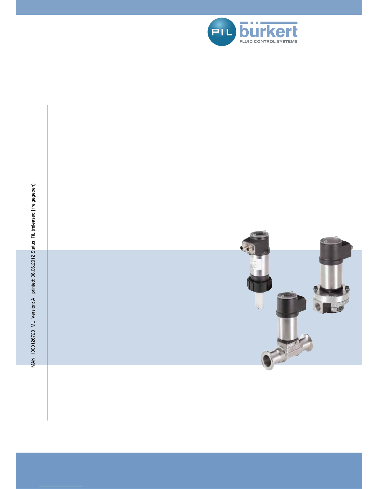
Type 8026 - 8036 - 8076
Flow rate transmitter
Durchfluss-Transmitter
Transmetteur de débit
Unit 173 Argyle Industrial Estate, Argyle Street, Nechells, Birmingham B7 5TE
www.pneutrolfluidcontrol.com sales@pneutrol.com Tel: +44 (0) 1213287288
Pneutrol International Limited

We reserve the right to make technical changes without notice.
Technische Änderungen vorbehalten.
Sous réserve de modification technique.
© 2009 Bürkert SAS
Operating Instructions 0912/00_EU-ML_00561367_Original_FR

1
Flow transmitters types 8026 - 8036 - 8076
Contents
1. ABOUT THIS MANUAL .............................................................................................................................................................................................5
1.1. Symbols used ................................................................................................................................................................................................5
2. INTENDED USE ............................................................................................................................................................................................................6
2.1. Restraints .........................................................................................................................................................................................................6
2.2. Foreseeable misuse ...................................................................................................................................................................................6
3. BASIC SAFETY INFORMATION ...........................................................................................................................................................................7
4. GENERAL INFORMATION .......................................................................................................................................................................................8
4.1. Contents of the delivery ........................................................................................................................................................................... 8
4.2. Warranty conditions ....................................................................................................................................................................................8
4.3. Information on the Internet.....................................................................................................................................................................8
5. DESCRIPTION ...............................................................................................................................................................................................................9
5.1. Area of application ......................................................................................................................................................................................9
5.2. General description ....................................................................................................................................................................................9
5.2.1. Construction of the 8026 ....................................................................................................................9
5.2.2. Construction of the 8036 ....................................................................................................................9
5.2.3. Construction of the 8076 ..................................................................................................................10
5.3. Description of the labels ........................................................................................................................................................................10
5.4. Versions of the 8026 available ...........................................................................................................................................................10
5.5. Versions of the SE36 electronic module available ..................................................................................................................11
6. TECHNICAL DATA .....................................................................................................................................................................................................12
6.1. Conditions of use .......................................................................................................................................................................................12
6.2. Conforming to standards and directives .......................................................................................................................................12
6.2.1. Conformities common to the 8026 and the SE36 ......................................................................12
6.2.2. Conformity to the Pressure Directive of 8026 transmitters and S030 and S070
fittings ....................................................................................................................................................12
english
Type 8026 - 8036 - 8076

2
6.3. General technical data ............................................................................................................................................................................12
6.3.1. Mechanical data ..................................................................................................................................12
6.3.2. General data .........................................................................................................................................16
6.3.3. Electrical data .......................................................................................................................................17
7. ASSEMBLY ....................................................................................................................................................................................................................18
7.1. Safety instructions ....................................................................................................................................................................................18
7.2. Unscrew the cover ....................................................................................................................................................................................18
7.3. Fitting the cover ..........................................................................................................................................................................................19
7.4. Fitting the display module (available as an accessory) ........................................................................................................19
7.5. Removing the display module (available as an accessory) ................................................................................................20
8. INSTALLATION AND WIRING ..............................................................................................................................................................................21
8.1. Safety instructions ....................................................................................................................................................................................21
8.2. Installation onto the pipe .......................................................................................................................................................................21
8.2.1. Recommendations on installing an 8026 or an 8036 on a pipe ..............................................21
8.2.2. Recommendations on installing an 8076 on a pipe....................................................................23
8.3. Electrical wiring ...........................................................................................................................................................................................23
8.3.1. Electrical connections ........................................................................................................................23
8.3.3. Assembling the male or female connector (accessories: see Chap. 12) ..............................24
8.3.4. Wiring a version with an M12 fixed connector and an NPN transistor output and
a current output ...................................................................................................................................24
8.3.5. Wiring a version with one M12 fixed connector and two transistor outputs and a
current output ......................................................................................................................................25
8.3.6. Wiring a version with two M12 fixed connectors and two transistor outputs and
two current outputs ............................................................................................................................27
9. COMMISSIONING .....................................................................................................................................................................................................30
9.1. Safety instructions ....................................................................................................................................................................................30
10. ADJUSTMENT AND FUNCTIONS......................................................................................................................................................................31
10.1. Safety instructions ....................................................................................................................................................................................31
10.2. Functions ........................................................................................................................................................................................................31
10.3. Using the browse button .......................................................................................................................................................................32
10.4. Example of a numerical value input ................................................................................................................................................34
10.5. Example of browsing in a menu ........................................................................................................................................................34
english
Type 8026 - 8036 - 8076

3
10.6. Description of the display .....................................................................................................................................................................35
10.6.1. Description of the icons and LEDs .................................................................................................35
10.6.2. When switching on the device .........................................................................................................36
10.7. Read mode ....................................................................................................................................................................................................36
10.8. Programming mode access .................................................................................................................................................................37
10.9. Structure of the programming menus............................................................................................................................................38
10.10. Parameters menu (“Param”) ................................................................................................................................................................41
10.10.1. Transfer certain data from one device to another (menu “System” - Function
“Up/Download”) ..................................................................................................................................41
10.10.2. Modify the PARAM menu access code (Menu “System” - Function “Code”) ......................42
10.10.3. Restore the default parameters for Read mode and outputs (Menu “System” -
Function “Factory Set”) .....................................................................................................................42
10.10.4. Set the parameters of the data displayed on lines 1 and 2 in the display module
(Menu “Display” - Functions “Line1” and “Line2”) ......................................................................42
10.10.5. Choose the units for the totalisers displayed in Read mode (Menu “Display” -
Function “Totalisers”) .........................................................................................................................44
10.10.6. Set the parameters for the display of the minimum and maximum values meas-
ured (Menu “Display” - Function “Min/Max”) ................................................................................44
10.10.7. Set the parameters for the reading comfort level of the data displayed (“Display”
menu) .....................................................................................................................................................44
10.10.8. Define the output connection mode (Menu “Outputs” - Function “HWMode”) ...................45
10.10.9. Setting the parameters for the current outputs (Menu “Outputs” - Functions
“AC1” and “AC2”) ...............................................................................................................................45
10.10.10. Set the parameters for the transistor outputs (Menu “Outputs” - Functions
“TR1” and “TR2”) ................................................................................................................................47
10.11. Calibration menu (“Calib”) ...................................................................................................................................................................49
10.11.1. Activate/deactivate the Hold function (Menu “System” - Function “Hold”) ...........................49
10.11.2. Modify the Calibration menu access code (Menu “System” - Function “Code”) .................49
10.11.3. Reset totaliser 1 or totaliser 2 respectively (Menu “System” - Functions “Total1”
and “Total2”) ........................................................................................................................................49
10.11.4. Adjust the current outputs (“Outputs” menu) ...............................................................................50
10.11.5. Input the K factor or determine it with Teach-in (“Sensor” menu) ...........................................50
10.12. Diagnostic menu (“Diagnostic”).........................................................................................................................................................53
10.12.1. Modify the Diagnostic menu access code (“System” menu) ....................................................53
10.12.2. Monitor the sensor input frequency (Menu “Sensor” - Function “Frequency”).....................53
10.13. Test menu (“Test”) .....................................................................................................................................................................................54
10.13.1. Modify the Test menu access code (“System” menu) ................................................................54
10.13.2. Check that the outputs are working correctly (“Outputs” menu) .............................................54
10.13.3. Check that the outputs are behaving correctly (“Sensor” menu) .............................................55
english
Type 8026 - 8036 - 8076

4
10.14. Information menu (“Info”) .....................................................................................................................................................................55
11. MAINTENANCE AND TROUBLESHOOTING ...............................................................................................................................................56
11.1. Safety instructions ....................................................................................................................................................................................56
11.2. Cleaning of the transmitter ...................................................................................................................................................................56
11.3. If you encounter problems ...................................................................................................................................................................56
12. SPARE PARTS AND ACCESSORIES ..............................................................................................................................................................58
13. PACKAGING, TRANSPORT ..................................................................................................................................................................................58
14. STORAGE ......................................................................................................................................................................................................................58
15. DISPOSAL OF THE DEVICE ................................................................................................................................................................................58
english
Type 8026 - 8036 - 8076
5
About this manual
ABOUT THIS MANUAL1.
This manual describes the entire life cycle of the device. Please keep this manual in a safe place, accessible to all users and
any new owners.
This manual contains important safety information.
Failure to comply with these instructions can lead to hazardous situations.
This manual must be read and understood. •
Symbols used1.1.
DANGER
Warns you against an imminent danger.
Failure to observe this warning can result in death or in serious injury.•
WARNING
Warns you against a potentially dangerous situation.
Failure to observe this warning can result in serious injury or even death. •
CAUTION
Warns you against a possible risk.
Failure to observe this warning can result in substantial or minor injuries. •
NOTE
Warns you against material damage.
Failure to observe this warning may result in damage to the device or system. •
indicates additional information, advice or important recommendations for your safety and for the correct operation of
the device.
refers to information contained in this manual or in other documents.
indicates a procedure to be carried out.
→
english
Type 8026 - 8036 - 8076

6
Intended use
INTENDED USE2.
Use of the transmitter that does not comply with the instructions could present risks to people, nearby installations
and the environment.
8026, 8036 and 8076 transmitters are intended to be used to measure the flow of liquids:•
8026 and 8036 transmitters are used to measure the flow of neutral or slightly aggressive liquids the 8076 transmitter is used to measure the flow of viscous liquids such as honey or oil, which are free of solid parti- -
cles.
This device must be protected against electromagnetic interference, ultraviolet rays and, when installed outdoors, the effects •
of climatic conditions.
This device must be used in compliance with the characteristics and commissioning and use conditions specified in the •
contractual documents and in the user manual.
Requirements for the safe and proper operation of the device are proper transport, storage and installation, as well as careful •
operation and maintenance.
Only use the device as intended.•
Restraints2.1.
Observe any existing restraints when the device is exported.
Foreseeable misuse2.2.
Do not use this device in explosive atmospheres.•
Do not use this device for measuring the flow of gas.•
Do not use this device in an environment incompatible with the materials from which it is made.•
Do not use fluid that is incompatible with the materials from which this device is made.•
Do not subject the device to mechanical loads (e.g. by placing objects on top of it or by using it as a step).•
Do not make any external modifications to the device. Do not paint or varnish any part of the device.•
english
Type 8026 - 8036 - 8076
7
Basic safety information
BASIC SAFETY INFORMATION3.
This safety information does not take into account:
any contingencies or occurences that may arise during assembly, use and maintenance of the devices.•
the local safety regulations that the operator must ensure the staff in charge of assembly and maintenance observe.•
Danger due to high pressure in the installation.
Danger due to electrical voltage.
Danger due to high temperatures of the fluid.
Danger due to the nature of the fluid.
Various dangerous situations.
To avoid injury take care to:
prevent any power supply switch-on.•
carry out installation and maintenance work by qualified and skilled staff with the appropriate tools.•
guarantee a set or controlled restarting of the process, after a power supply interruption.•
use the device only if in perfect working order and in compliance with the instructions provided in the user manual.•
observe the general technical rules during the planning and use of the device.•
NOTE
Chemical compatibility of materials in contact with the fluid.
Systematically check the chemical compatibility of the component materials of the transmitter and the products likely to come •
into contact with it (for example: alcohols, strong or concentrated acids, aldehydes, alkaline compounds, esters, aliphatic
compounds, ketones, halogenated aromatics or hydrocarbons, oxidants and chlorinated agents).
NOTE
Elements / Components sensitive to electrostatic discharges
This device contains electronic components sensitive to electrostatic discharges. They may be damaged if they are touched •
by an electrostatically charged person or object. In the worst case scenario, these components are instantly destroyed or
go out of order as soon as they are activated.
To minimise or even avoid all damage due to an electrostatic discharge, take all the precautions described in the EN 100 •
015-1 norm.
Also ensure that you do not touch any of the live electrical components. •
This device was developed with due consideration given to accepted safety rules and is state-of-the-art. However, risks
may arise.
Failure to observe these instructions as well as any unauthorised work on the device excludes us from any liability and also
nullifies the warranty which covers the device and its accessories.
english
Type 8026 - 8036 - 8076
8
General information
GENERAL INFORMATION4.
Contents of the delivery4.1.
When you receive the merchandise, make sure that the contents of the delivery have not been damaged in any way and
ensure that they correspond exactly with the delivery note or packing list. If this is not the case, contact your retailer
immediately.
The addresses of our international branches can be found on the last pages of this manual. They can also be found on the
Internet under: www.burkert.com
Bürkert Company Locations.
Warranty conditions4.2.
The condition to benefit from the warranty is the conforming use of flow transmitters types 8026, 8036 and 8076 in observance
of the operating conditions specified in this user manual.
The terms and conditions of any warranty are governed by our general terms and conditions of sale.
The warranty only extends to defects in transmitter types 8026, 8036 and 8076 and their components.
Bürkert cannot be held responsible for any losses or damage related to the product, the service, this warranty or other,
including financial or intangible losses, the price paid for the product, a loss of profits, revenues, data, enjoyment or use
of the product or of any related product, or indirect or fortuitous loss or damage.
In the event of differences in interpretation and understanding of this paragraph 4.2, the French version alone shall prevail.
Information on the Internet4.3.
You can find the user manuals and technical data sheets regarding types 8026, 8036 and 8076 on the internet at:
www.burkert.fr
Technical data sheets Technical data sheets or User Manuals/Approvals Type 8026, 8036, 8076 and
SE36
The complete manual can be ordered under code: 561367.
english
Type 8026 - 8036 - 8076
9
Description
DESCRIPTION5.
Area of application5.1.
8026, 8036 and 8076 transmitters are intended solely for the measurement of the flow of liquids:
8026 and 8036 transmitters are used to measure the flow of neutral or slightly aggressive liquids•
the 8076 transmitter is used to measure the flow of viscous liquids such as honey or oil, which are free of solid particles.•
Thanks to 1 or 2 transistor outputs, the transmitter can be used to switch a solenoid valve, activate an alarm and, thanks to 1
or 2 4-20 mA current outputs, establish one or two control loops.
General description5.2.
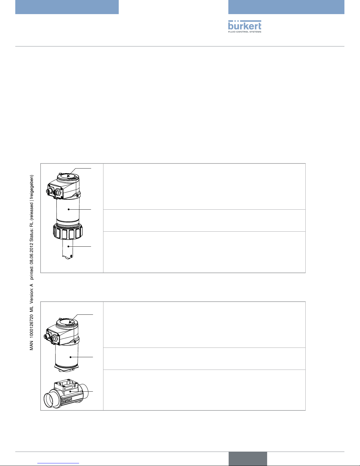
Construction of the 80265.2.1.
The 8026 transmitter comprises:
!
"
#
A: a paddle-wheel flow sensor, the rotation of which generates pulses.
Set in rotation by the flow
, the 4 permanent magnets integrated in the vanes of the paddle
generate pulses, the frequency of which is proportional to the flow speed of the fluid. A conversion coefficient specific to each pipe (material and diameter) is necessary to establish the
flow value associated with the measurement.
The conversion coefficient (Factor K) expressed in pulses per litre is given in the user manual
for the fitting used.
B: an acquisition / conversion module for the physical parameters measured:
acquisition of the pulse frequency•
conversion of the frequency measured into flow units•
C: a display module with browse button used to read and/or configure the parameters of the
device. The display module is available as an accessory.
See Chapter 12.
Construction of the 80365.2.2.
The 8036 transmitter comprises:
!
"
#
A: an S030 fitting including the paddle-wheel flow sensor.
Set in rotation by the flow
, the 4 permanent magnets integrated in the vanes of the paddle
generate pulses, the frequency of which is proportional to the flow speed of the fluid. A conversion coefficient specific to each pipe (material and diameter) is necessary to establish the
flow value associated with the measurement.
The conversion coefficient (Factor K) expressed in pulses per litre is given in the user manual
for the fitting used.
B: an acquisition / conversion module for the physical parameters measured:
acquisition of the pulse frequency•
conversion of the frequency measured into flow units•
C: a display module with browse button used to read and/or configure the parameters of the
device. The display module is available as an accessory.
See Chapter 12.
english
Type 8026 - 8036 - 8076

10
Description
Construction of the 80765.2.3.
The 8076 transmitter comprises:
!
"
#
A: an S070 fitting including the oval-wheel flow sensor.
Set in rotation by the flow
, the magnets integrated in the oval gears generate pulses, the
frequency of which is proportional to the volume of fluid. A conversion coefficient specific to
each fitting is necessary to establish the flow value associated with the measurement.
The conversion coefficient (Factor K) expressed in pulses per litre is given in the user manual
for the fitting used.
B: an acquisition / conversion module for the physical parameters measured:
acquisition of the pulse frequency•
conversion of the frequency measured into flow units•
C: a display module with browse button used to read and/or configure the parameters of the
device. The display module is available as an accessory.
See Chapter 12.
Description of the labels5.3.
Ц&LOW-ETER
3UPPLYЦ6$#
/UTPUTЦXM!ЦX4RANSISTORSЦЦM!Ц-AX
#ELLЦ(!,,Ц).3%24)/.Ц3(/24
0ROCESSЦ4EMPЦК#
ЦЦЦЦЦЦЦЦЦЦЦЦЦЦЦ0.ЦЦ"AR
)0ЦЦЦЦЦЦЦЦЦЦЦЦ7,5
3.
-ADEÖINÖ&RANCEÖ
Ö
Ö
Ö
Ö
Ö
Ö
Ö
Ö
Ö
Ö
Ö
6Ö
.0.0.0Ö
6Ö
.0.0.0Ö
Fig. 5.1 Label on a flow transmitter
Type of transmitter and parameter measured1.
Electrical power supply2.
Output specifications3.
Sensor Type4.
Temperature range of the fluid5.
Nominal pressure of the fluid6.
Allocation of the pins on the M12 fixed connectors7.
Manufacturer code8.
Order code9.
Serial number10.
Protection rating11.
Versions of the 8026 available5.4.
The following versions of the 8026 flow transmitter are available. These references include the electronic module and the flow
sensor.
The display module is an accessory. See Chapter 12.
english
Type 8026 - 8036 - 8076
11
Description
Supply
voltage
Outputs
Electrical connection
Sensor
Type
Sensor
seal
UL recognised
Output connection type
Order code
for the 8026
14-36 VDC 1 x transistor NPN +
1 x 4-20 mA
M12, 5-pin male fixed
connector
Short FKM
1)
no 2 wire
560860
Long FKM
1)
560870
Short FKM
1)
yes 2 wire
560863
Long FKM
1)
560873
2 x transistor NPN/
PNP + 1 x 4-20 mA
M12, 5-pin male fixed
connector
Short FKM
1)
no 2 wire
560861
Long FKM
1)
560871
Short FKM
1)
yes 2 wire
560864
Long FKM
1)
560874
12-36 VDC 2 transistor NPN/
PNP + 2 x 4-20 mA
M12, 5-pin male fixed
connector and M12,
5-pin female fixed
connector
Short FKM
1)
no 3 wire
560862
Long FKM
1)
560872
Short FKM
1)
yes 3 wire
560865
Long FKM
1)
560875
1)
A set of extra seals (a seal in green FKM + a seal in black EPDM) is provided with each device.
Versions of the SE36 electronic module available5.5.
The following versions of the SE36 electronic module, used in an 8036 or 8076 flow transmitter, are available. The references
of the S030 and S070 fittings including the flow sensor can be found on the relevant technical data sheets for these product
types.
The display module is an accessory. See Chapter 12.
Supply
voltage
Outputs Electrical connection
Output connection
type
UL recognised
Order code
for the SE36
14-36 VDC 1 x transistor NPN +
1 x 4-20 mA
M12, 5-pin male fixed connector 2 wire no
560880
yes
560883
2 x transistor NPN/
PNP + 1 x 4-20 mA
M12, 5-pin male fixed connector 2 wire no
560881
yes
560884
12-36 VDC 2 x transistor NPN/
PNP + 2 x 4-20 mA
M12, 5-pin male fixed connector
and M12, 5-pin female fixed connector
3 wire no
560882
yes
560885
english
Type 8026 - 8036 - 8076
12
Technical data
TECHNICAL DATA6.
Conditions of use6.1.
Ambient temperature: -10 à +60°C (operating)
Air humidity: < 85%, non condensated
Protection rating: IP67 and IP65 with connectors plugged in and tightened and electronic module cover fully
screwed down
Conforming to standards and directives6.2.
Conformities common to the 8026 and the SE366.2.1.
EMC: EN 61000-6-2 (2005), EN 61000-6-3 (2001)•
Vibration: EN 60068-2-6•
Shock: EN 60068-2-27•
And, for UL recognized devices (
) in the United States of America and Canada, with variable key PE72:
UL 61010-1•
CAN/CSA-C22.2 No. 61010-1•
Conformity to the Pressure Directive of 8026 transmitters and S030 6.2.2.
and S070 fittings
8026 devices and S030 and S070 fittings comply with the requirements of Article 3 of §3 of the Pressure Directive.
According to Pressure Directive 97/23/EC, the product can only be used in the following cases (depending on the max. pres-
sure, pipe diameter and the type of fluid):
Type of fluid Conditions
Fluid group 1 § 1.3.a
8026 transmitter and S030 fitting: DN•
≤ 25 only
S070 fitting: forbidden•
Fluid group 2 § 1.3.a DN ≤ 32
or DN > 32 and PNxDN
≤ 1000
Fluid group 1 § 1.3.b 8026 transmitter: DN • ≤ 25 or DN > 25 and PNxDN ≤ 2000
S030 and S070 fittings: PNxDN • ≤ 2000
Fluid group 2 § 1.3.b 8026 transmitter: DN • ≤ 400
S030 and S070 fittings: DN•
≤ 200
General technical data6.3.
Mechanical data6.3.1.
Component Material
Box / seals stainless steel 1.4404, PPS / EPDM
Cover / seal PC / EPDM
Display module PC / PBT
M12 fixed connector nickel-plated brass
Fixed connector base stainless steel 1.4404 (316L)
english
Type 8026 - 8036 - 8076
13
Technical data
Component Material
Screw stainless steel
Tightening nut PC
Flow sensor armature / seal (8026 only) PVDF / FKM (by default)
Paddle axis and brackets (8026 only) Ceramic (Al
2O3
)
Paddle (8026 only) PVDF
Quarter-turn system (SE36 only) PC
PC
EPDM
PPS
EPDM
PVDF
PC
Stainless steel
Nickel-plated
brass
PPS
PVDF
Ceramic (Al
2O3
)
FKM
PC
EPDM
PPS
EPDM
Stainless steel
Nickel-plated
brass
PC
Fig. 6.1 Materials used in the 8026 transmitter and the SE36 electronic module for the 8036 or 8076 transmitter
Materials in the 8026 in contact with the fluid: PVDF, ceramic, FKM (by default)•
english
Type 8026 - 8036 - 8076
14
Technical data
140
131
97
70
(
DN H [mm]
with S030 fitting
06 160
08 160
15 165
20 163
25 163
32 166
40 170
50 177
65 177
(
DN H [mm]
with S070 fitting
15 166
25 181
40 198
50 216
80 256
100 257
Fig. 6.2 Dimensions of the SE36 electronic module and dimension H of the 8036 and 8076 transmitters
english
Type 8026 - 8036 - 8076
15
Technical data
ÖÖÖ
Ö
Ö
Ö
1)
With short sensor / with long sensor
(
DN of the
fitting
H [mm] with S020 fitting type:
[mm] T-fitting Flange
fitting
Bush in
plastic
material
Bush in
stainless
steel
15 231.5
20 229.5
25 229.5
32 232.5.
40 236.5
50 242.5 267.5 237.5
65 242.5 265.5 250.5 243.5
80 270.5 256.5 248.5
100 275.5 263.5 258.5
110 271.5
125 278.5 298.5 269.5
150 248.5 305.5 280.5
180 312.5
200 324.5 326.5 301.5
250 344.5 361.5
300 356.5 380.5
350 369.5 392.5
400 384.5
Fig. 6.3 Dimensions of the 8026 transmitter and dimension H when the 8026 transmitter is inserted in an S020 fitting
!
06#Ö0.
00Ö0.
4ÖÊ#
0ÖBAR
06#ÖÖ00
06$&Ö0.
Ö0.
06$&Ö
metal
metal
A: operating range
Fig. 6.4 Fluid pressure / temperature dependency for a transmitter type 8026 inserted into an S020 fitting
english
Type 8026 - 8036 - 8076
16
Technical data
!
06$&Ö0.
06#Ö0.
00Ö0.
4ÖÊ#
0ÖBAR
06$&
0.
06#ÖÖ00
metal
A: operating range
Fig. 6.5 Fluid pressure / temperature dependency for a transmitter type 8036 (SE36 associated to an S030 fitting with PVDF paddle-wheel)
General data6.3.2.
Diameter of the conduits DN06 to DN400;
For an S020 or S030 fitting, the appropriate diameter is determined
using the flow/DN/fluid speed graphs: refer to the user manuals for the
fittings
Type of fitting S020 for the 8026 transmitter: see corresponding manual•
S030 for the 8036 transmitter: see corresponding manual•
S070 for the 8076 transmitter: see corresponding manual•
Fluid temperature
8026•
8036 with S030 fitting in PVC •
1)
8036 with S030 fitting in PP •
1)
8036 with S030 fitting in PVDF •
1)
, brass 1) or
stainless steel
1)
8076 with S070 fitting in aluminium•
8076 with S070 fitting in stainless steel•
-15 to +100°C; Also factor in the temperature/pressure dependency •
of the 8026 inserted into an S020 fitting: see fig. 6.4
0 to +50°C; Also factor in the temperature/pressure dependency of •
the 8036: see fig. 6.5
0 to +80°C; Also factor in the temperature/pressure dependency of •
the 8036: see fig. 6.5
-15 to +80°C; Also factor in the temperature/pressure dependency •
of the 8036: see fig. 6.5
max. +80°C •
max. +100°C•
Fluid pressure
8026•
8036•
8076 with S070 fitting DN15•
8076 with S070 fitting DN25•
8076 with S070 fitting DN40 or DN50•
8076 with S070 fitting DN80•
8076 with S070 fitting DN100•
Also refer to the requirements of the Pressure Directive: see § 6.2.2
PN10 ; Also factor in the temperature/pressure dependency of the •
8026 inserted into an S020 fitting: see fig. 6.4
PN16; Also factor in the temperature/pressure dependency of the •
8036: see fig. 6.5
max. 55 bar•
max. 55 bar (or the rules governing the flanges)•
max. 18 bar•
max. 12 bar•
max. 10 bar•
Type of fluid
8026 and 8036•
8076•
Neutral or slightly aggressive fluids•
Viscous fluids, free of solid particles•
english
Type 8026 - 8036 - 8076
17
Technical data
Fluid viscosity
8026 and 8036•
8076•
300 cSt. max.•
Refer to the manual for the S070 fitting•
Solid particle rate in the fluid
8026 and 8036•
8076•
≤• 1%
0 %•
Flow measurement
Measurement range•
Linearity•
Repeatability•
Measurement error with standard K factor•
Measurement error with Teach-in•
0,3 to 10 m/s•
±0,5% •
2)
of the full scale
±0,4% •
2)
of the measured value
±2,5% •
2)
of the measured value
±1% •
2)
of the measured value
1)
with PVDF paddle-wheel
2)
under the following reference conditions: fluid water, water and ambient temperatures at 20 °C, applying the minimum upstream and down-
stream pipe straights, matched inside pipe dimensions
Electrical data6.3.3.
Power supply
version with 2 or 3 outputs (2 wires)•
version with 4 outputs (3 wires)•
14-36 VDC, filtered and regulated•
12-36 VDC, filtered and regulated•
Characteristics of the power source (not provided) of UL recognized devices, with variable
key PE72
limited power source (in accordance with § 9.3 of the UL 61010-1 •
standard)
or class 2 type power source (according to the 1310/1585 and 60950-1 •
standards)
Power consumption
version with 2 or 3 outputs (2 wires)•
version with 4 outputs (3 wires)•
25 mA max. (at 14 VDC)•
5 mA max. (at 12 VDC)•
Consumption, with charges on transistors 1 A max.
Power consumed 40 W max.
Protection against polarity reversal
yes
Protection against spike voltages
yes
Protection against short circuits
yes, for the transistor outputs
Transistor output
version with a single transistor output•
version with 2 transistor outputs•
NPN, open collector, 700 mA max., 1-36 VDC•
NPN (/sink) or PNP (/source) (depending on programming), open collec-•
tor, 700 mA max., 500 mA max. per transistor if the 2 transistor outputs
are wired
NPN output: 1-36 VDC
PNP output: supply voltage
Current output
version with a single current output (2 wires)•
version with 2 current outputs (3 wires)•
4-20 mA, sink (“NPN sink”) or source (“PNP source”) (depending on programming)
max. loop impedance: 1100•
Ω at 36 VDC, 610 Ω at 24 VDC, 180 Ω at
14 VDC
max. loop impedance: 1100•
Ω at 36 VDC, 610 Ω at 24 VDC, 100 Ω at
12 VDC
english
Type 8026 - 8036 - 8076

18
Assembly
ASSEMBLY7.
Safety instructions7.1.
DANGER
Risk of injury due to electrical discharge.
Shut down and isolate the electrical power source before carrying out work on the system.•
Observe all applicable accident protection and safety regulations for electrical equipment.•
WARNING
Risk of injury due to non-conforming assembly.
Assembly must be done only by qualified and authorised personnel with the appropriate tools.•
Risk of injury due to unintentional switch on of power supply or uncontrolled restarting of the installation.
Take appropriate measures to avoid unintentional activation of the installation.•
Guarantee a set or controlled restarting of the process subsequent to the assembly of the device.•
Unscrew the cover7.2.
NOTE
The tightness of the transmitter is not guaranteed when the cover is removed.
Take any precautions necessary to prevent the projection of fluid inside the box once the cover has been removed.•
The transmitter may be damaged if a metal component comes into contact with the electronics.
Take any precautions necessary to prevent contact of the electronics with a metal component (screwdriver, for example). •
To unscrew the cover, use your hand or a tool which can be used as →
a lever, taking care not to scratch the glass
Turn the cover until fully unscrewed →
Fig. 7.1 Unscrewing the cover
Fitting the cover7.3.
Check that there is a seal on the cover and that it is not damaged. →
Replace it if necessary.
Grease the seal if necessary using a component compatible with the
→
material from which it is made.
english
Type 8026 - 8036 - 8076
19
Assembly
Fully tighten by hand to guarantee tightness. →
Fig. 7.2 Fitting the cover
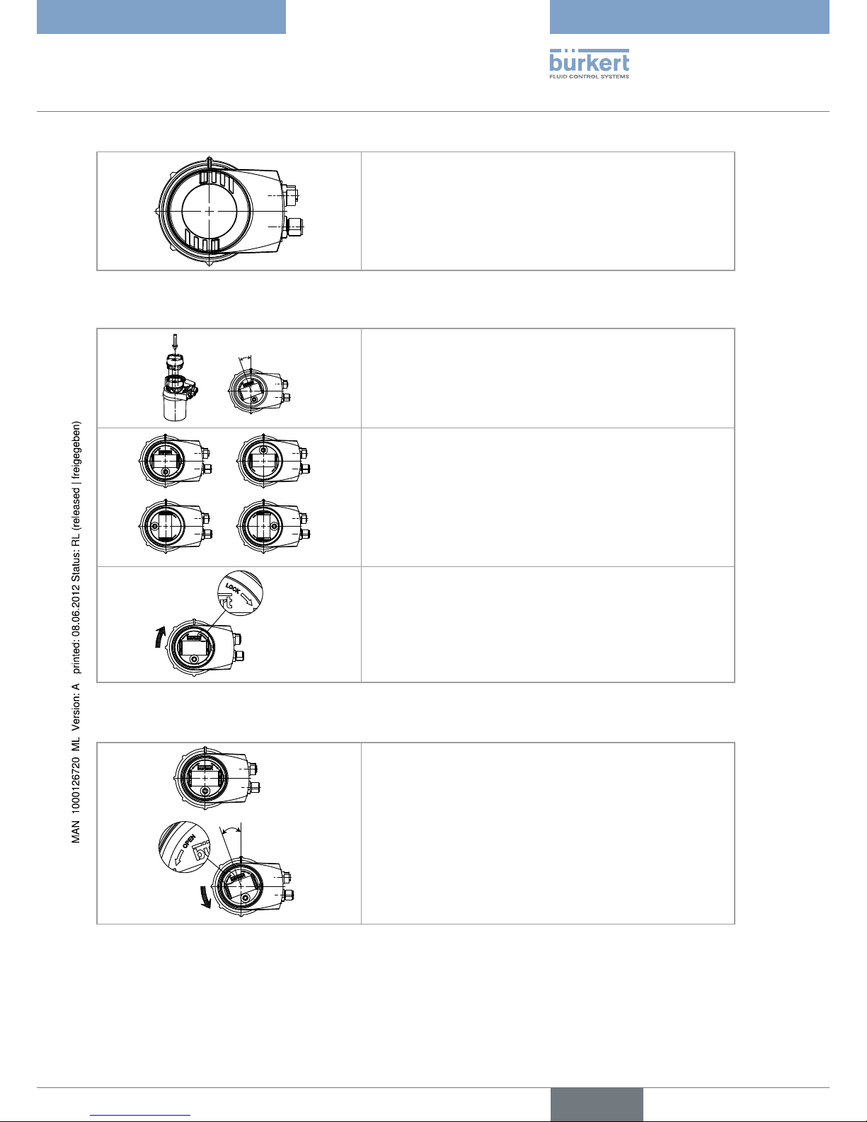
Fitting the display module (available as an accessory)7.4.
ÊÖ
Unscrew the cover (see § 7.2).
→
Set the display module at an angle of ca. 20° in relation to the desired →
position.
AÖ
BÖ
CÖ
DÖ
The module can be fitted in 4 different positions, at 90° intervals.
→
Fully push in the module and turn to the right to lock it. →
Fig. 7.3 Fitting the display module
Removing the display module (available as an accessory)7.5.
Ê
Unscrew the cover if necessary (see § 7.2). →
Turn the module by ca. 20° to the left. Once unlocked, the module is →
raised slightly by the spring action.
english
Type 8026 - 8036 - 8076
20
Assembly
Remove the module from its housing. →
Fig. 7.4 Removing the display module
english
Type 8026 - 8036 - 8076
21
Installation and wiring
INSTALLATION AND WIRING8.
Safety instructions8.1.
DANGER
Risk of injury due to high pressure in the installation.
Stop the circulation of fluid and release the pressure in the pipes before detaching the device from the pipe.•
Risk of injury due to electrical discharge.
Shut down and isolate the electrical power source before carrying out work on the system.•
Observe all applicable accident protection and safety regulations for electrical equipment.•
Risk of injury due to the nature of the fluid.
Respect the prevailing regulations on accident prevention and safety relating to the use of aggressive fluids.•
WARNING
Risk of injury due to non-conforming installation.
The electrical and fluid installation can only be carried out by qualified and skilled staff with the appropriate tools.•
Install appropriate safety devices (correctly rated fuse and/or circuit-breaker).•
Respect the assembly instructions for the connector used.•
Risk of injury due to unintentional switch on of power supply or uncontrolled restarting of the installation.
Take appropriate measures to avoid unintentional activation of the installation.•
Guarantee a set or controlled restarting of the process subsequent to the assembly of the device.•
Installation onto the pipe8.2.
DANGER
Risk of injury due to high pressure in the installation.
Stop the circulation of fluid and release the pressure in the pipes before detaching the device from the pipe.•
Risk of injury due to the nature of the fluid.
Respect the prevailing regulations on accident prevention and safety relating to the use of aggressive fluids.•
Recommendations on installing an 8026 or an 8036 on a pipe8.2.1.
CAUTION
Risk of damage when installing the fitting.
Respect the installation instructions given in the user manual for the fitting.•
Install the fitting on the pipe, respecting the instructions given in the manual for the fitting used.
→
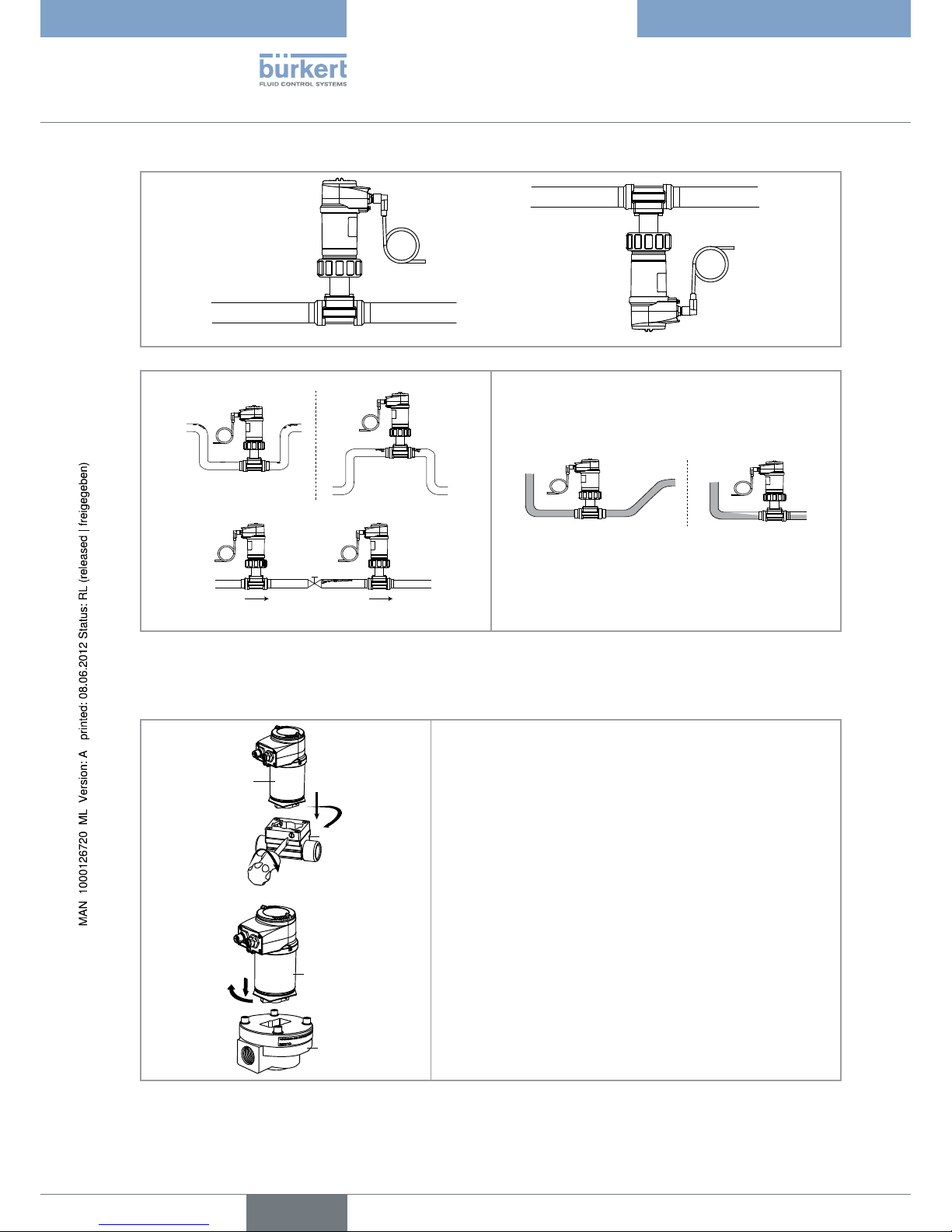
Respect the following additional conditions of installation to ensure that the device operates correctly (Fig. 8.1 and 8.2). →
Install the device in such a way that the paddle axis is horizontal. Prevent the formation of air bubbles in the pipe in the section around the sensor. Ensure that the pipe is always filled in the section around the sensor. -
english
Type 8026 - 8036 - 8076
22
Installation and wiring
Fig. 8.1 : The paddle axis must be horizontal
Correct
Correct
In cor rect
In cor rect
Fluid circulation direction
Correct
In cor rect
Fig. 8.2 Air bubbles in the pipes / filling the pipes
Fit the display module (see § 7.4) to be able to programme the transmitter →
Assemble the 8036 transmitter (see figure 8.3 below) or install the 8026 transmitter in the S020 fitting (see figure 8.4 →
opposite)
3%
3
3%
3
1 : Inserting the electronic module into the fitting holder. →
2 : Turn the electronic module by a quarter turn. →
3 : Secure the electronic module and the S030 fitting only, by tightening →
the screw with a suitable tool to a max. tightening torque of 1 Nm.
Fig. 8.3 Assembly of the SE36 on an S030 or S070 fitting
english
Type 8026 - 8036 - 8076
23
Installation and wiring
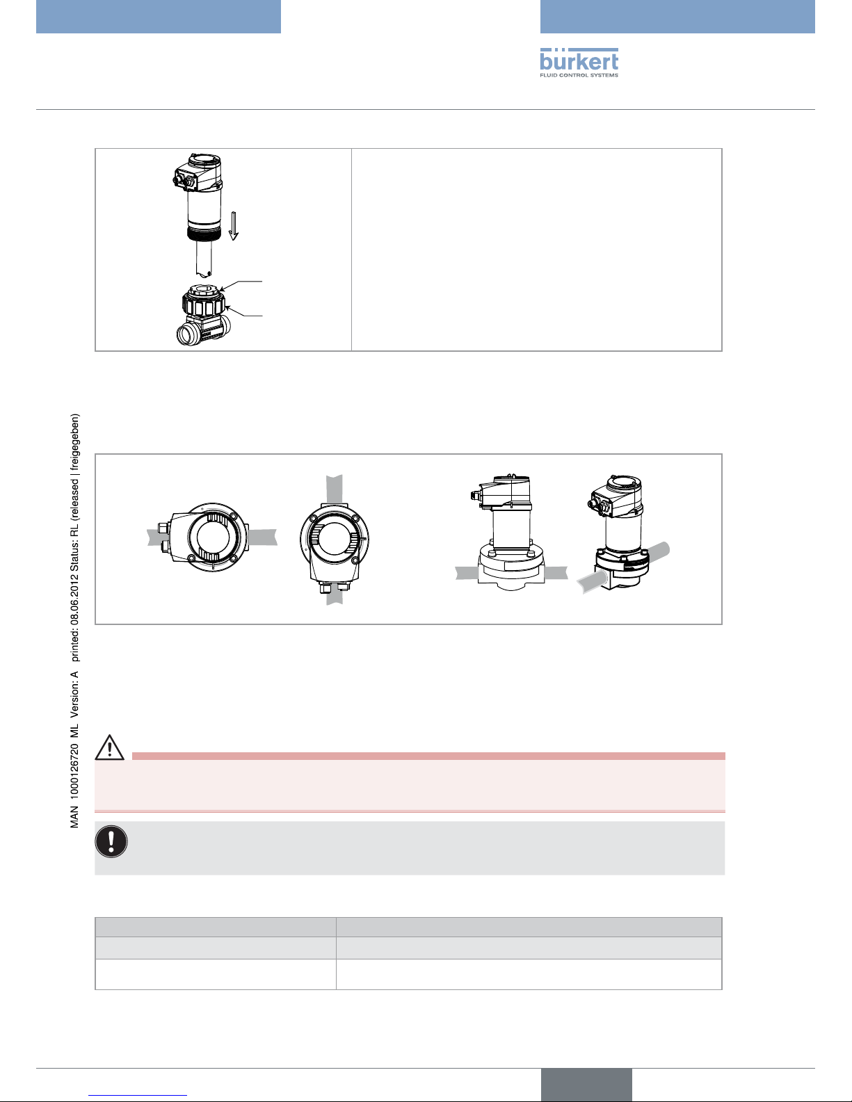
!
"
Check that there is a seal on the fitting and that it is not damaged.
→
Replace the seal if necessary.
Place nut A on the fitting and insert circlip B into the groove. →
Carefully insert the transmitter into the fitting. If assembly is correct, →
the transmitter can no longer rotate on itself.
Secure the unit with nut A, tightening only by hand.
→
Fig. 8.4 Installation of the 8026 transmitter in the S020 fitting
Programme the K factor (see § 10.11.5) or determine it using Teach-in →
Recommendations on installing an 8076 on a pipe8.2.2.
Install the S070 fitting on the pipe in such a way that the oval gear axes are in the horizontal plane, as shown in Fig. 8.5. →
Correct In cor rect
Fig. 8.5 The oval gear axes must be horizontal (seen from the front)
Fit the display module (see § 7.4) to be able to programme the transmitter →
Assemble the 8076 transmitter (see Fig. 8.3) →
Programme the K factor (see § 10.11.5) or determine it using Teach-in →
Electrical wiring8.3.
DANGER
Risk of injury due to electrical discharge.
Shut down and isolate the electrical power source before carrying out work on the system.•
Observe all applicable accident protection and safety regulations for electrical equipment.•
Use a high quality electrical power supply (filtered and regulated).•
Guarantee the equipotentiality of the installation.•
Use shielded cable•
Electrical connections8.3.1.
Number of fixed connectors: Type of cable plug
1 M12 male fixed connector M12 female, 5 pins (available as an accessory: see Chap. 12)
1 M12 male fixed connector + 1 M12 female
fixed connector
M12 female, 5 pins (available as an accessory: see Chap. 12) + M12 male,
5 pins (available as an accessory: see Chap. 12)
english
Type 8026 - 8036 - 8076
24
Installation and wiring
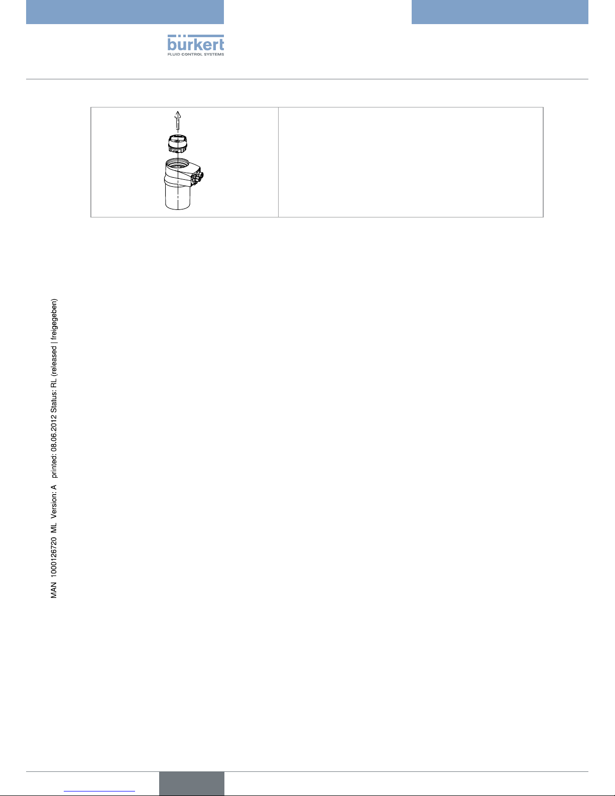
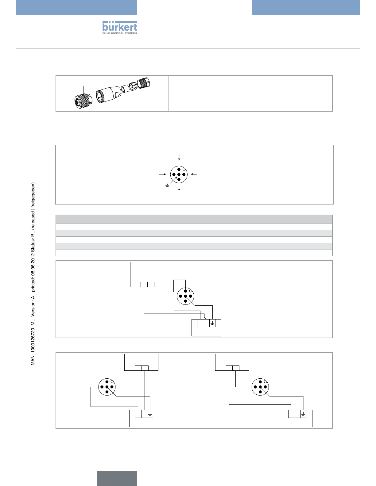
Assembling the male or female connector (accessories: see Chap. 12)8.3.3.
Completely unscrew the nut [1] →
Remove the rear section of the connector [2]. →
Make the connections (see 8.3.2 or 8.3.3) →
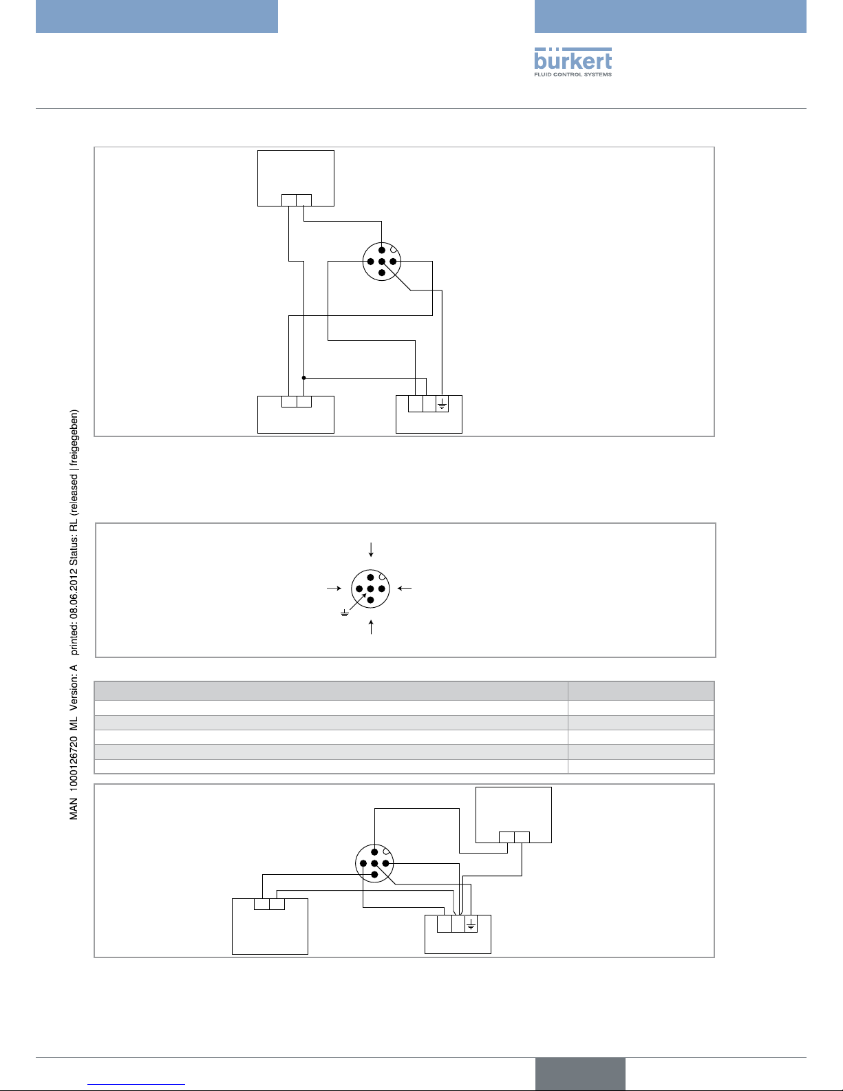
Fig. 8.6 M12 multi-pin connector (available as an accessory)
Wiring a version with an M12 fixed connector and an NPN transistor 8.3.4.
output and a current output
V+ (14-36 VDC)
NPN transistor output (TR1)
Not connected
0V
Fig. 8.7 Wiring of the male fixed connector on a version with 1 NPN transistor output and 1 current output
Pin for the M12 female cable available as optional equipment (order code 438680) Colour of the conductor
1 brown
2 white
3
blue
4 black
5
grey
Ö6$#
Ö Ö
Ö
Ö
Ö
Ö
Power supply
Charge
(solenoid valve,
for example)
white
blue
brown
grey
Fig. 8.8 Connection of the NPN transistor output (“NPN/sink” software programming not modifiable, see § 10.10.8) on a version with 1 M12
fixed connector, 1 NPN transistor output and 1 current output
Ö6$#
Power supply
Input
4-20 mA
brown
blue
grey
Ö6$#
Power supply
Input
4-20 mA
brown
blue
grey
Fig. 8.9 Connection of the current output only, in source mode or sink mode, on a version with 1 M12 fixed connector, 1 NPN transistor
output and 1 current output
english
Type 8026 - 8036 - 8076
25
Installation and wiring
Ö6$#
Ö Ö
Ö Ö
Ö
Ö
Ö
Ö
Charge
Input
4-20 mA
brown
grey
blue
white
Power supply
Fig. 8.10 Fig. 8.10 Connection of the NPN transistor output and the current output, in NPN/sink mode (“NPN/sink” software programming
not modifiable, see § 10.10.8) on a version with 1 M12 fixed connector, 1 NPN transistor output and 1 current output
Wiring a version with one M12 fixed connector and two transistor 8.3.5.
outputs and a current output
V+ (14-36 VDC)
Transistor output 1 (TR1)
Transistor output 2 (TR2)
0V
Fig. 8.11 Wiring the male fixed connector on a version with 2 transistor outputs and 1 current output
Pin for the M12 female cable available as optional equipment (order code 438680) Colour of the conductor
1 brown
2 white
3 blue
4 black
5
grey
Ö6$#
Charge 1
(solenoid valve,
for example)
Charge 2
(solenoid valve,
for example)
Power supply
white
blue
black
brown
grey
Fig. 8.12 Connection of the 2 transistor outputs, in NPN mode (“NPN/sink” software programming, see § 10.10.8) on a version with 1 M12
fixed connector
english
Type 8026 - 8036 - 8076
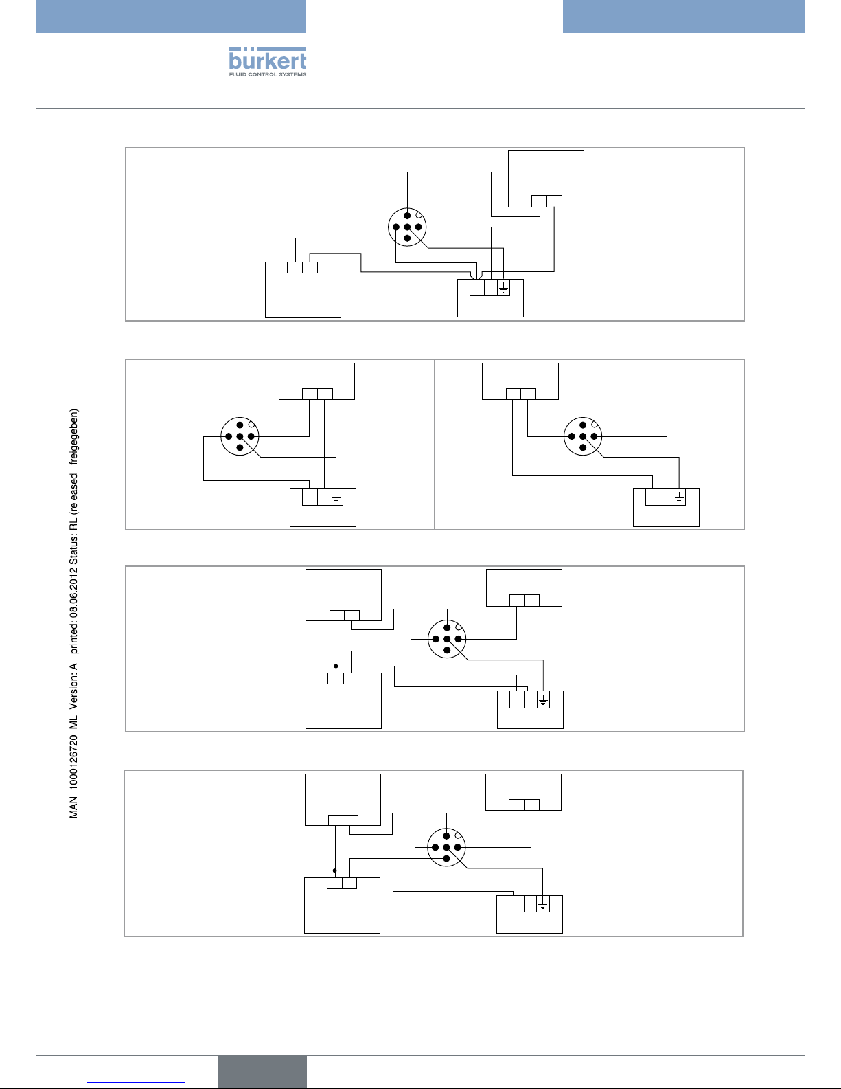
26
Installation and wiring
Ö6$#
Charge 1
(solenoid valve,
for example)
Charge 2
(solenoid valve,
for example)
Power supply
white
blue
black
brown
grey
Fig. 8.13 Connection of the 2 transistor outputs, in PNP mode (“PNP/source” software programming, see § 10.10.8) on a version with 1
M12 fixed connector
Ö6$#
Power supply
Input
4-20 mA
brown
blue
grey
Ö6$#
Power supply
Input
4-20 mA
brown
blue
grey
Fig. 8.14 Connection of the current output only, in source mode or sink mode (regardless of the software programming, “NPN/sink” or “PNP/
source”, see § 10.10.8) on a version with 1 M12 fixed connector
Ö6$#
Charge 2
Charge 1
Entrée
4-20 mA
brown
grey
blue
white
black
Power supply
Fig. 8.15 Connection of the 2 transistor outputs and the current output, in NPN/sink mode (“NPN/sink” software programming, see
§ 10.10.8) on a version with 1 M12 fixed connector
Ö6$#
Charge 2
Charge 1
Input
4-20 mA
brown
grey
blue
white
black
Power supply
Fig. 8.16 Connection of the 2 transistor outputs and the current output, in PNP/source mode (“PNP/source” software programming, see
§ 10.10.8) on a version with 1 fixed connector
english
Type 8026 - 8036 - 8076
 Loading...