

Page 1
Type 8025/8035
Flowmeter-Totalizer, battery-powered
Durchflussmessgerät-Mengenzähler mit Batterien
Débitmètre-totalisateur à piles
Operating Instructions
Bedienungsanleitung
Manuel d‘utilisation
Page 2

We reserve the right to make technical changes without notice.
Technische Änderungen vorbehalten.
Sous réserve de modifications techniques.
© 2013 Bürkert SAS
Operating Instructions 1307/1_EU-ML 00564407 Original_FR
Page 3
Type 8025/8035 battery powered
1. ABOUT THIS MANUAL .................................................................................3
1.1. Symbols used....................................................................................3
1.2. Definition of the word "device" ......................................................3
2. INTENDED USE ................................................................................................4
3. BASIC SAFETY INFORMATION ...............................................................4
4. GENERAL INFORMATION ...........................................................................6
4.1. Manufacturer's address and international contacts .................6
4.2. Warranty conditions .........................................................................6
4.3. Information on the Internet ............................................................. 6
5. DESCRIPTION ...................................................................................................6
5.1. Area of application ........................................................................... 6
5.2. General description ......................................................................... 6
5.3. Description of the name plates ..................................................... 6
5.4. Available versions .............................................................................7
6. TECHNICAL DATA ...........................................................................................7
6.1. Conditions of use ............................................................................. 7
6.2. Conformity to standards and directives ...................................... 7
6.3. General technical data ....................................................................8
6.3.1. Mechanical data ....................................................................8
6.3.2. General data .........................................................................10
7. INSTALLATION ............................................................................................... 11
7.1. Safety instructions .........................................................................11
7.2. Installation onto the pipe ..............................................................12
7.2.1. Installation of the fitting onto the pipe ............................12
7.2.2. Installation of 8025 on the S020 fitting .........................14
7.2.3. Installation of the SE35 electronic module on
the S030 fitting-sensor ......................................................14
7.3. Description of the electronic board connections....................14
8. OPERATING AND COMMISSIONING.................................................15
8.1. Safety instructions .........................................................................15
8.2. Switch on the device and lock/unlock the ENTER key ........15
8.3. Operating levels of the device ....................................................16
8.4. Description of the navigation keys .............................................17
8.5. Details of the Process level .........................................................18
8.6. Details of the Configuration level ...............................................18
8.6.1. Choosing the display language .......................................19
8.6.2. Choosing the flow rate units, the number of
decimals and the units of the totalizers ..........................19
8.6.3. Entering or determining the K factor of the
fitting used ...........................................................................21
8.6.4. Configuring the filter ...........................................................23
8.6.5. Resetting both totalizers ....................................................23
9. MAINTENANCE AND TROUBLESHOOTING ..................................23
9.1. Safety instructions .........................................................................23
9.2. Cleaning the device .......................................................................24
9.3. Cleaning the flow sensor of the 8025 .......................................24
9.4. Replacing the batteries .................................................................24
English
1
Page 4
9.5. If you encounter problems ............................................................25
10. SPARE PARTS AND ACCESSORIES ...............................................25
10.1. SE35 electronic module .............................................................25
10.2. 8025 flowmeter-totalizer ............................................................26
11. PACKAGING, TRANSPORT ...................................................................26
12. STORAGE ....................................................................................................... 26
13. DISPOSAL OF THE PRODUCT ........................................................... 27
Type 8025/8035 battery powered
2
English
Page 5
Type 8025/8035 battery powered
About this manual
1. ABOUT THIS MANUAL
This manual describes the entire life cycle of the device. Please
keep this manual in a safe place, accessible to all users and any new
owners.
This manual contains important safety information.
Failure to comply with these instructions can lead to hazardous
situations.
• This manual must be read and understood.
1.1. Symbols used
danger
Warns against an imminent danger.
• Failure to observe this warning can result in death or in serious
injury.
Warning
Warns against a potentially dangerous situation.
• Failure to observe this warning can result in serious injury or
even death.
attention
Warns against a possible risk.
• Failure to observe this warning can result in substantial or minor
injuries.
note
Warns against material damage.
• Failure to observe this warning may result in damage to the
device or system.
Indicates additional information, advice or important
recommendations.
Refers to information contained in this manual or in other
documents.
→ Indicates a procedure to be carried out.
1.2. Definition of the word "device"
The word "device" used within this manual refers to the battery
powered flowmeter-totalizer type 8025 or 8035.
English
3
Page 6
Type 8025/8035 battery powered
Intended use
2. INTENDED USE
Use of the device that does not comply with the instructions
could present risks to people, nearby installations and the
environment.
• The flowmeter-totalizer 8025 or 8035 is intended to measure
the flow rate and totalize the volume of liquid.
• This device must be protected against electromagnetic interference, ultraviolet rays and, when installed outdoors, the effects
of climatic conditions.
• This device must be used in compliance with the characteristics
and commissioning and use conditions specified in the contractual documents and in the user manual.
• Requirements for the safe and proper operation of the device
are proper transport, storage and installation, as well as careful
operation and maintenance.
• Only use the device as intended.
→ Observe any existing restraints when the device is exported.
3. BASIC SAFETY INFORMATION
This safety information does not take into account:
• any contingencies or occurences that may arise during installation,
use and maintenance of the devices.
• the local safety regulations for which the operating company
is responsible including the staff in charge of installation and
maintenance.
Danger due to high pressure in the installation.
• Stop the circulation of fluid, cut off the pressure and drain the
pipe before loosening the process connections.
Danger due to electrical voltage.
• Put the power switch to OFF before carrying out work on the
device.
• Shut down and isolate the electrical power source before carrying out work on the system.
• Observe all applicable accident protection and safety regulations for
electrical equipment.
Danger due to high temperatures of the fluid.
• Use safety gloves to handle the device.
• Stop the circulation of fluid and drain the pipe before loosening
the process connections.
Danger due to the nature of the fluid.
• Respect the prevailing regulations on accident prevention and safety
relating to the use of aggressive fluids.
4
English
Page 7
Type 8025/8035 battery powered
Basic safety information
Various dangerous situations
To avoid injury take care:
• not to use the device for the measurement of gas flow rates.
• not to use the device in explosive atmospheres.
• not to use the device in an environment incompatible with the
materials it is made of.
• not to use fluid that is incompatible with the materials the device
is made of.
• not to subject the device to mechanical loads (e.g. by placing
objects on top of it or by using it as a step).
• not to make any external or internal modifications to the device.
• to prevent any unintentional power supply switch-on.
• to ensure that installation and maintenance work are
carried out by qualified, authorised personnel in possession of
the appropriate tools.
• to use the device only if in perfect working order and in compliance with the instructions provided in the operating instructions.
• to observe the general technical rules when installing and using
the device.
note
The device may be damaged by the fluid in contact with.
• Systematically check the chemical compatibility of the component materials of the device and the fluids likely to come into
contact with it (for example: alcohols, strong or concentrated
acids, aldehydes, alkaline compounds, esters, aliphatic compounds, ketones, halogenated aromatics or hydrocarbons,
oxidants and chlorinated agents).
note
Elements / Components sensitive to electrostatic discharges
• This device contains electronic components sensitive to electrostatic discharges. They may be damaged if they are touched by
an electrostatically charged person or object. In the worst case
scenario, these components are instantly destroyed or go out of
order as soon as they are activated.
• To minimise or even avoid all damage due to an electrostatic
discharge, take all the precautions described in the EN 613405-1 and 5-2 norms.
• Also ensure that you do not touch any of the live electrical
components.
English
5
Page 8
1
2
Type 8025/8035 battery powered
General information
4. GENERAL INFORMATION
4.1. Manufacturer's address and international contacts
To contact the manufacturer of the device, use following address:
Bürkert SAS
Rue du Giessen
BP 21
F-67220 TRIEMBACH-AU-VAL
You may also contact your local Bürkert sales office.
The addresses of our international sales offices are available on the
internet at: www.burkert.com
4.2. Warranty conditions
The condition governing the legal warranty is the conforming use
of the 8025 or the 8035 in observance of the operating conditions
specified in this manual.
4.3. Information on the Internet
You can find the user manuals and technical data sheets regarding
the type 8035 or 8025 at: www.burkert.com
5. DESCRIPTION
5.1. Area of application
The battery powered flowmeter-totalizer 8025 or 8035 is intended
to measure the flow rate and totalize the volume of liquid.
5.2. General description
The device type 8025 is made up of a flow sensor with paddle
wheel and an electronic module with display.
The device type 8035 is made up of an SE35 electronic module
and of an S030 fitting-sensor incorporating the paddle wheel which
measure the flow.
The device is fed with 2 batteries.
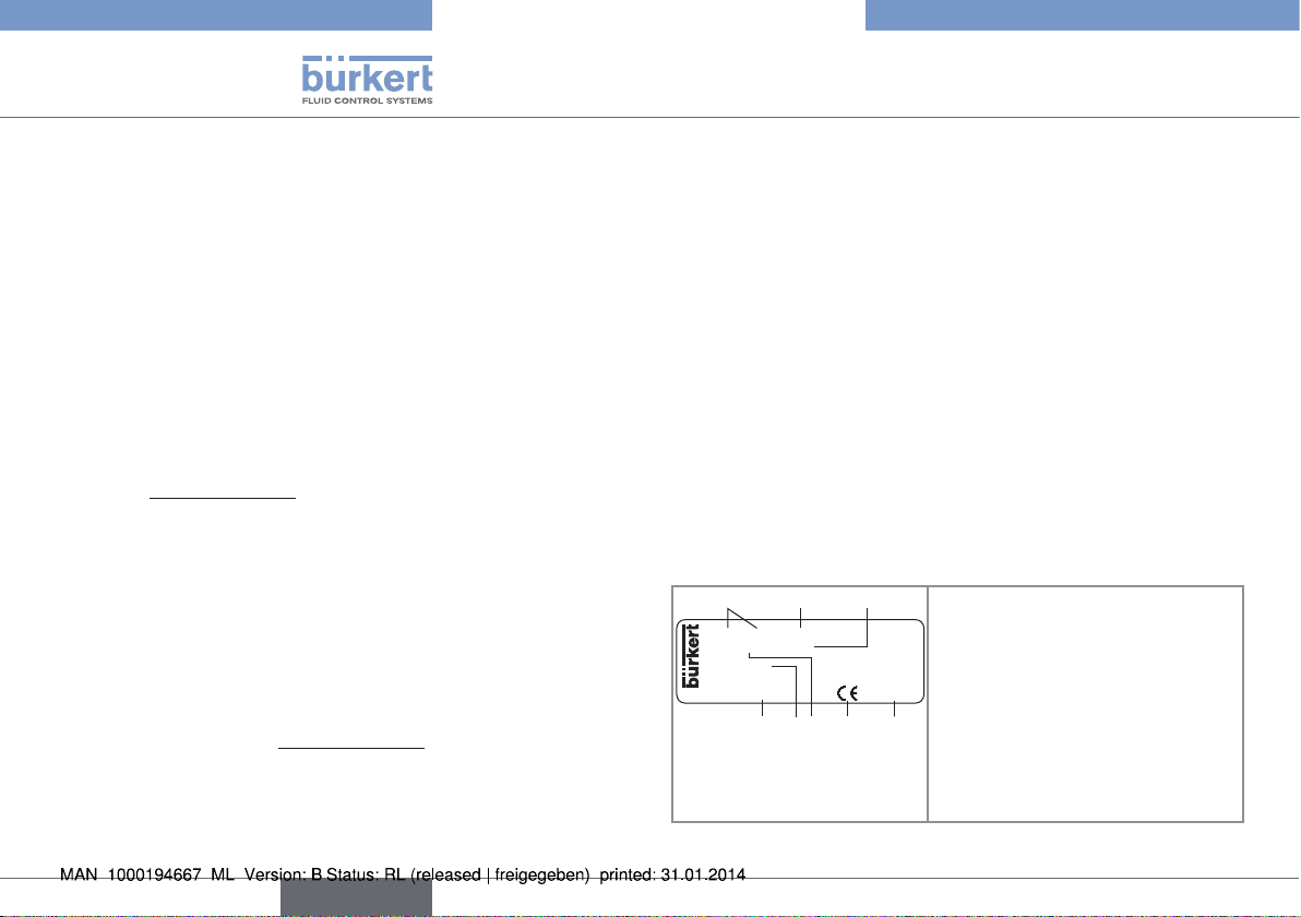
5.3. Description of the name plates
1. Type of the device
TOTAL :8025- SUPPLY: BATT9V
COIL SHORT - OUT: /
S/N 1439
Made in France
00418403 W43MA
Fig. 1: Name plate of the
8025
2. Power supply
3. Type of output: without
4. Manufacturing code
5. Conformity logo
457836
6. Specification of the flow sensor
7. Serial number
8. Order code
6
English
Page 9

1 2
Type 8025/8035 battery powered
Technical data
1. Type of the device
TOTAL :SE35/8035 COIL 9V
IP65
S/N 1439
Made in France
00423921 W43MA
2. Specification of the flow sensor
3. Power supply
4. Manufacturing code
5. Conformity logo
457836
6. Protection rating
Fig. 2: Name plate of the
8035
7. Serial number
8. Order code
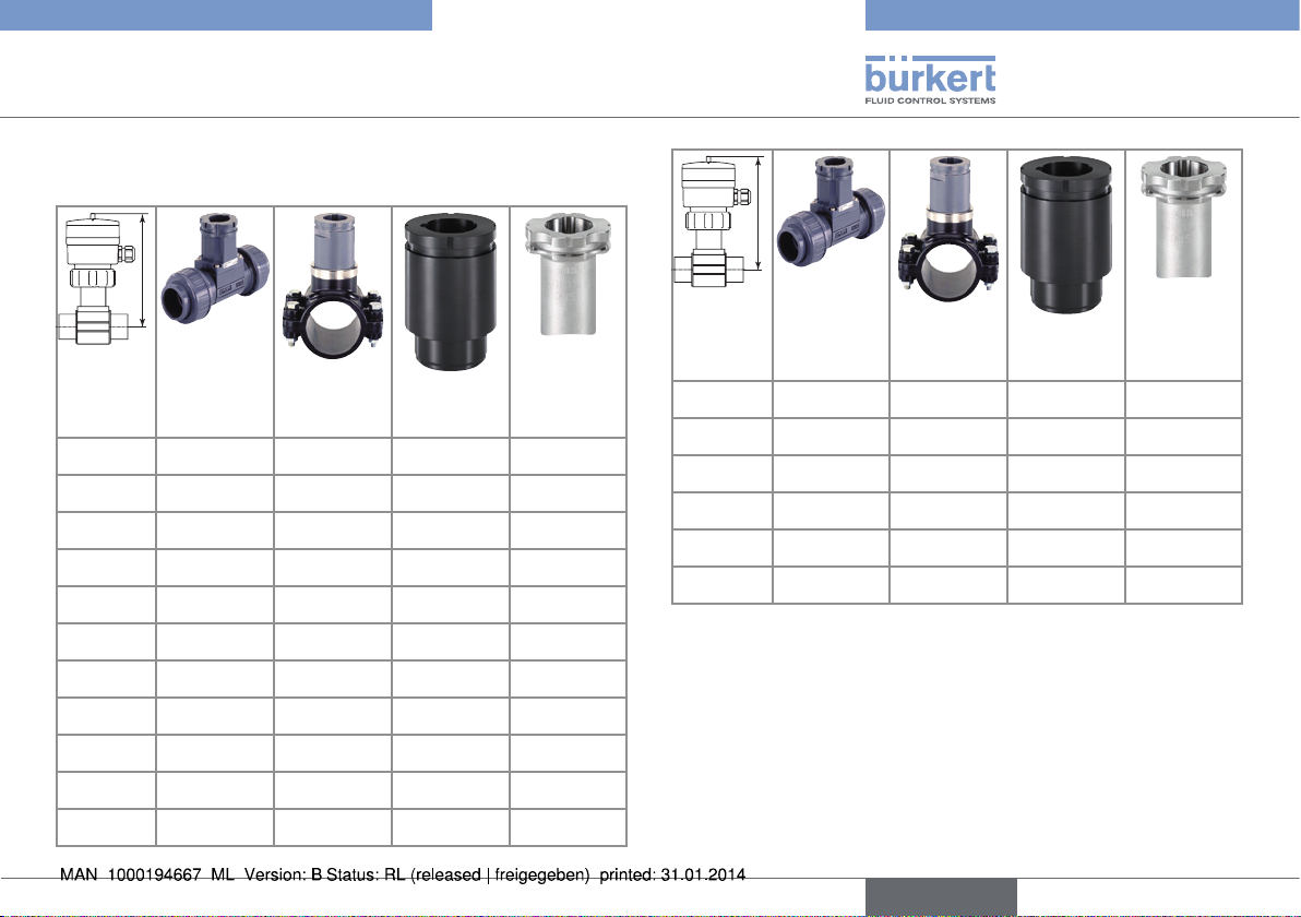
5.4. Available versions
• The flowmeter-totalizer type 8035 is made up of an SE35 elec-
tronic module with order code 423921 and of an S030 fittingsensor which has to be ordered separately.
• The flowmeter-totalizer type 8025 exists in 2 versions:
Type of flow sensor Seal material Order code
short, with coil FKM
long, with coil FKM
418403
418405
6. TECHNICAL DATA
6.1. Conditions of use
Ambient temperature 0 to +60 °C
Air humidity < 80%, without condensation
Height above see
level
Protection rating IP65, cover lid screwed tight and screwed
6.2. Conformity to standards and directives
The device conforms to the EC directives through the following
standards:
• EMC: EN 61000-6-2, EN 61000-6-3
• LVD: EN 61 010-1
• Vibration: EN 60068-2-6
• Shock: EN 60068-2-27
• Pressure: article 3§3 of the Pressure Directive 97/23/CE. Acc. to
the Pressure Directive 97/23/CE: the device can only be used in
the following cases (depending on the max. pressure, the DN of
the pipe and the fluid)
max. 2000 m
plugs.
English
7
Page 10
203
Type 8025/8035 battery powered
Technical data
Type of fluid Conditions
8025 8035
Fluid group 1 §
1.3.a
Fluid group 2 §
1.3.a
Fluid group 1 §
1.3.b
Fluid group 2 §
1.3.b
1)
For the type 8035 : S030 fitting-sensor, DN6 to DN65, in PP,
only DN25 DN ≤ 25
DN ≤ 32
or DN > 32 and
PNxDN ≤1000
DN ≤ 32
or DN > 32 and
PNxDN ≤ 1000
DN ≤ 25
or DN > 25 and
PNxDN ≤ 2000
PNxDN≤ 2000
DN ≤ 400 DN ≤ 200
PVC, PVDF, brass or stainless steel.
6.3. General technical data
6.3.1. Mechanical data
Part Material
Housing / seal PC / NBR
Cover with lid / seal PC / silicone
Front foil Polyester
1)
Screws Stainless steel
Nut PC
Part Material
Flow sensor (exposed to the
PVDF / FKM
fluid) / seal (only with 8025)
Axis and bearings of the paddle
ceramic
wheel
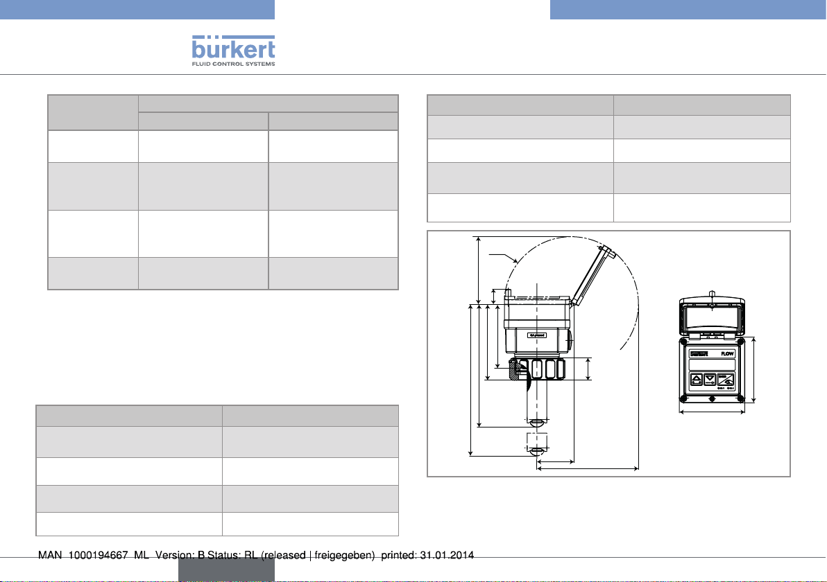
R=90
91
21
85.5
102
164.5
49.5
30
88
136
88
Fig. 3: Dimensions in mm of the 8025
M20x1.5 screw plugs / seal PA / neoprene
8
English
Page 11
Type 8025/8035 battery powered
Technical data
Table 1: Height H in mm of flowmeter-totalizer 8025 associated to
an S020 fitting
H
H
T-fitting
Saddle
Spigot, in
plastic
Welding tab
with radius,
in stainless
steel
DN20 185
DN25 185
DN32 188
DN40 192 188
DN50 198 223 193
DN65 198 221 206 199
DN80 226 212 204
DN100 231 219 214
DN110 227
DN125 234 254 225
DN150 244 261 236
T-fitting
Saddle
Spigot, in
plastic
Welding tab
with radius,
in stainless
steel
DN180 268
DN200 280 282 257
DN250 300 317
DN300 312 336
DN350 325 348
DN400 340
English
9
Page 12
Type 8025/8035 battery powered
Technical data
180
91
21
88
88
95
105
75
104
114
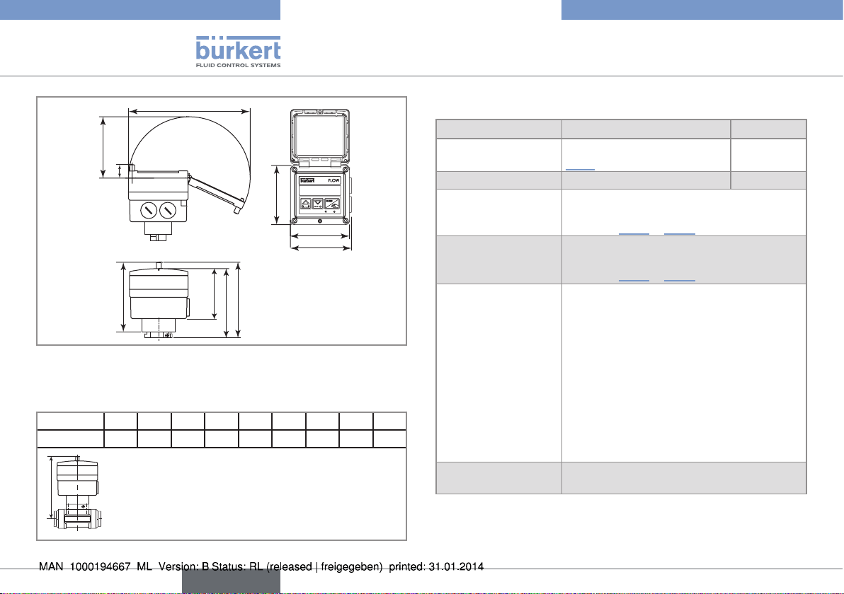
Fig. 4: Dimensions in mm of the SE35 electronic module
Table 2: Height H in mm of SE35 electronic module associated to
an S030 fitting-sensor
DN (mm) 06 08 15 20 25 32 40 50 65
H (mm) 134 134 139 137 137 140 144 151 151
1)
H
The height H does not
depend on the type of connection or on the material.
6.3.2. General data
Type 8025 8035
Pipe diameter
Type of fitting S020 S030
Fluid temperature
Fluid pressure
Flow rate measurement
• Measurement range
• Measurement error
with a teach-in
procedure (teach-in
function)
• Measurement error
with K factor of fitting
used
• Linearity
• Repeatability
Power supply 2 batteries of 9 V (6LR61)
1)
Determined in the following reference conditions: fluid = water,
water and ambient temperatures = 20 °C, upstream and downstream distances respected, appropriate pipe dimensions.
DN20 (except for DN specified
p.13) to DN400
DN6 to
DN65
The fluid temperature may be restricted by the
fluid pressure and by the material of the fitting
used. See Fig. 5 et Fig. 6
The fluid pressure may be restricted by the fluid
temperature and by the material of the fitting
used. See Fig. 5 et Fig. 6
• 0,2 to 10 m/s
• ±0,5 % of the full scale
• ± (0,5% of the full scale + 2,5 % of the
measured value) 1)
• ±0,5 % of the full scale 1)
• ±0,4 % of the measured value
Minimum autonomy: 1 year at 20° C
10
English
Page 13
11
Type 8025/8035 battery powered
Installation
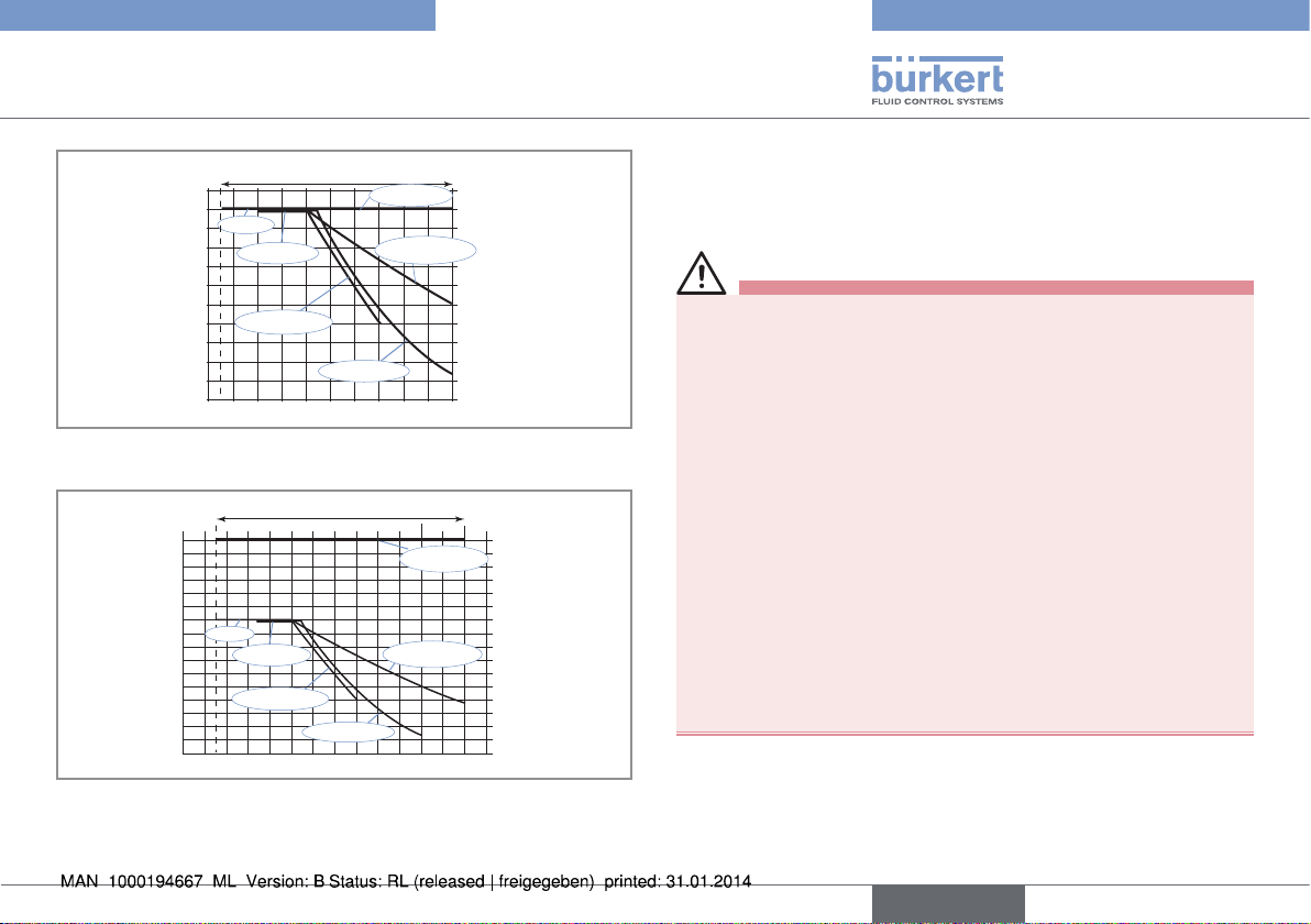
PVDF
PVC + PP
PVC (PN10)
application range
Metal
PVDF (PN10)
PP (PN10)
+80
P fluid (bar)
10
9
8
7
6
5
4
3
2
1
0
-15 0 +20 +40+60
Fig. 5: Type 8025, temperature-pressure dependency curves,
depending on the S020 fitting material
application range
PVC + PP
PVC (PN10)
A
Metal
PVDF (PN10)
PP (PN10)
P fluid (bar)
16
15
14
13
12
11
10
9
PVDF
8
7
6
5
4
3
2
1
0
-10 +10 +30 +50+70 +90 +110
-30
Fig. 6: Type 8035, temperature-pressure dependency curves,
depending on the S030 sensor-fitting material
T fluid (°C)
T fluid (°C)
7. INSTALLATION
7.1. Safety instructions
danger
Risk of injury due to high pressure in the installation.
• Stop the circulation of fluid, cut off the pressure and drain the
pipe before loosening the process connections.
Risk of injury due to electrical voltage.
• Shut down and isolate the electrical power source before carrying out work on the system.
• Put the power switch to OFF before carrying out work on the
device.
• Observe all applicable accident protection and safety regulations for electrical equipment.
Risk of injury due to high fluid temperatures.
• Use safety gloves to handle the device.
• Stop the circulation of fluid and drain the pipe before loosening
the process connections.
Risk of injury due to the nature of the fluid.
• Respect the prevailing regulations on accident prevention and
safety relating to the use of aggressive fluids.
English
11
Page 14
Warning
Risk of injury due to non-conforming installation.
• The fluid installation can only be carried out by qualified and
skilled staff with the appropriate tools.
• Respect the assembly instructions for the fitting used.
Risk of injury due to unintentional switch on of power supply
or uncontrolled restarting of the installation.
• Take appropriate measures to avoid unintentional activation of
the installation.
• Ensure that the restart of the installation is controlled after any
interventions.
Protect this device against electromagnetic interference, ultraviolet rays and, when installed outdoors, the
effects of the climatic conditions.
7.2. Installation onto the pipe
danger
Type 8025/8035 battery powered
Installation
The 8025 flowmeter-totalizer has to be inserted into an S020 fitting
mounted on a pipe.
The SE35 electronic module has to be inserted into an S030 fittingsensor mounted on a pipe.
7.2.1. Installation of the fitting onto the pipe
→ Choose an S020 or S030 fitting appropriate to the velocity of
the fluid inside the pipe: refer to the graphs at right.
→ Install the fitting on the pipe as described in the operating
instructions of the fitting used.
Risk of injury due to high pressure in the installation.
• Stop the circulation of fluid, cut off the pressure and drain the
pipe before loosening the process connections.
Risk of injury due to the nature of the fluid.
• Respect the prevailing regulations on accident prevention and
safety relating to the use of aggressive fluids.
12
English
Page 15
gpm
Type 8025/8035 battery powered
Installation
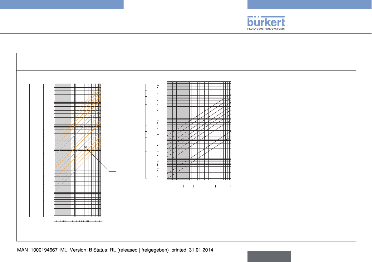
Table 3: Diagram flow/ fluid velocity/ DN of S020 fitting (on left) and S030 fitting-sensor (on right)
Example: for a nominal flow = 10 m3/h and an optimal flow velocity between 2 and 3 m/s.
→ use a DN40 fitting (or DN50 for the asterisked fittings).
US gpm
20000
10000
5000
2000
1000
500
200
100
50
20
10
5
2
1
0.5
0.2
0.1
0.05
Flow rate
l/min
100000
50000
30000
20000
10000
5000
3000
2000
1000
500
200
100
50
20
10
5
2
1
0.5
0.2
3
/h
m
5000
2000
1000
500
200
100
50
20
10
5
2
1
0.5
0.2
0.1
0.05
0.02
0.01
0.10.3 0.51 35 10
0.30.5 13510
Fluid velocity
DN 400
DN 350
DN 300
DN 250
DN 200
DN 150
DN 125
DN 100
DN 80
DN 65
DN 50 (DN65)*
DN 40 (DN50)*
DN 32 (DN40)*
DN 25 (DN32)*
DN 20 (DN25)*
Example
m/s
30
fps
Flow rate
m3/h
l/min
2000
1000
500
200
100
50
20
10
1)
0.5
0.2
0.1
0.05
500
5000
200
2000
100
1000
50
500
20
200
10
100
5
50
2
20
5
2
1
1
10
0.5
5
3
0.2
2
0.1
1
0.05
0.5
0.02
0.3
0.2
0.01
0.1 0.2 0.3 0.5 1235 10
0.3 0.5 1235 10 20 30
Fluid velocity
* For the fittings:
• with external thread connections acc. to SMS 1145,
• with welding end connections acc. to SMS 3008, BS 4825 / ASME BPE or DIN 11850 Rg 2,
• Clamp acc. to SMS 3017 / ISO 2852, BS 4825 / ASME BPE or DIN 32676.
1)
The device cannot be installed on the DN20 fittings listed above
DN 65
(DN65)*
DN 50
DN 40
(DN50)*
DN 32
(DN40)*
DN 25
(DN32)*
DN 20
(DN25)*
DN 15
(DN15 / DN20)*
DN 08
DN 06
m/s
fps
English
13
Page 16
Type 8025/8035 battery powered
Installation
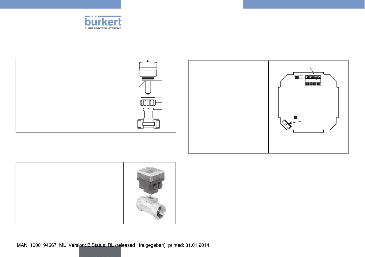
7.2.2. Installation of 8025 on the S020 fitting
→ Insert nut 3 on the fitting 5.
→ Insert the snap ring 2 into the groove 4.
→ Check that seal 6 is correctly inserted on the
flow sensor.
→ Slowly insert the device 1 into the fitting.
If the mounting is correctly done the device cannot
turn around anymore.
6
1
2
→ Hand lock the assembly with the nut 3.
Fig. 7: Installation of 8025 on the S020 fitting
7.2.3. Installation of the SE35 electronic module on the S030 fitting-sensor
→ Insert the electronic module 2 in the
S030 fitting-sensor.
→ Secure with a 30° clockwise rotation.
→ Tighten the lateral screw 3 to lock
the electronic module with the
fitting-sensor.
3
7.3. Description of the electronic board connections
Terminal block:
+ : positive supply (red wire)
- : negative supply (black wire)
3
4
5
2
1
Connector : branchement du
capteur de débit
Terminal block
OFF ON
Connector
Fig. 9: Electronic board
connections
Fig. 8: Installation of the SE35 electronic module on the S030
fitting-sensor
14
English
Page 17

Type 8025/8035 battery powered
Operating and commissioning
8. OPERATING AND COMMISSIONING
8.1. Safety instructions
Warning
Risk of injury due to non-conforming operating.
Non-conforming operating could lead to injuries and damage the
device and its surroundings.
• The operators in charge of operating must have read and understood the contents of this manual.
• In particular, observe the safety recommendations and intended
use.
• The device/installation must only be operated by suitably trained
staff.
Warning
Danger due to non-conforming commissioning.
Non-conforming commissioning could lead to injuries and damage
the device and its surroundings.
• Before commissioning, make sure that the staff in charge have
read and fully understood the contents of the manual.
• In particular, observe the safety recommendations and intended
use.
• The device / the installation must only be commissioned by
suitably trained staff.
8.2. Switch on the device and lock/ unlock the ENTER key
→ Unfasten the screw and flip
the lid.
→ Unfasten the 4 screws and
take off the cover of the
housing.
Switch on the device:
→ Put the switch 1 to ON
ENTER key unlocked
Fig. 11: Lock and unlock the ENTER key
Switch 1
OFF ON
Switch 2: see
Fig. 11
Fig. 10: Electronic board
ENTER key locked
English
15
Page 18
ENTER
Type 8025/8035 battery powered
Operating and commissioning
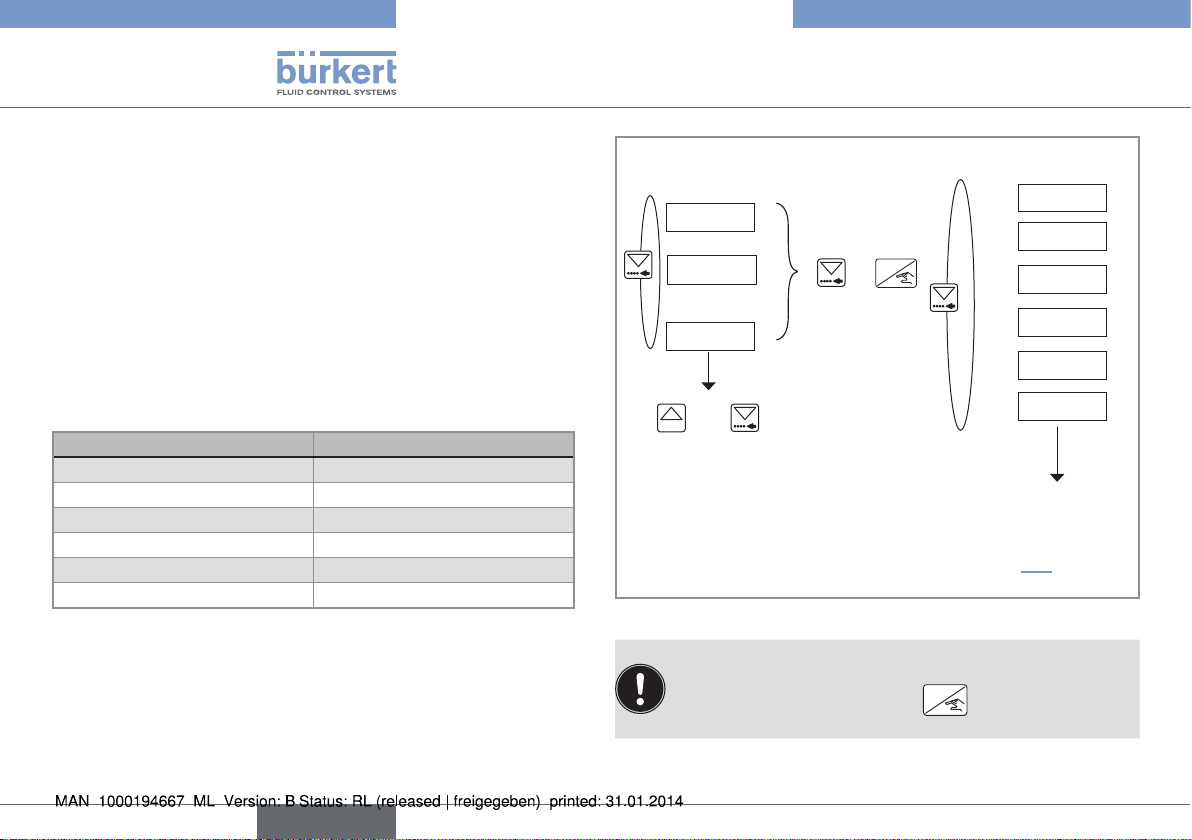
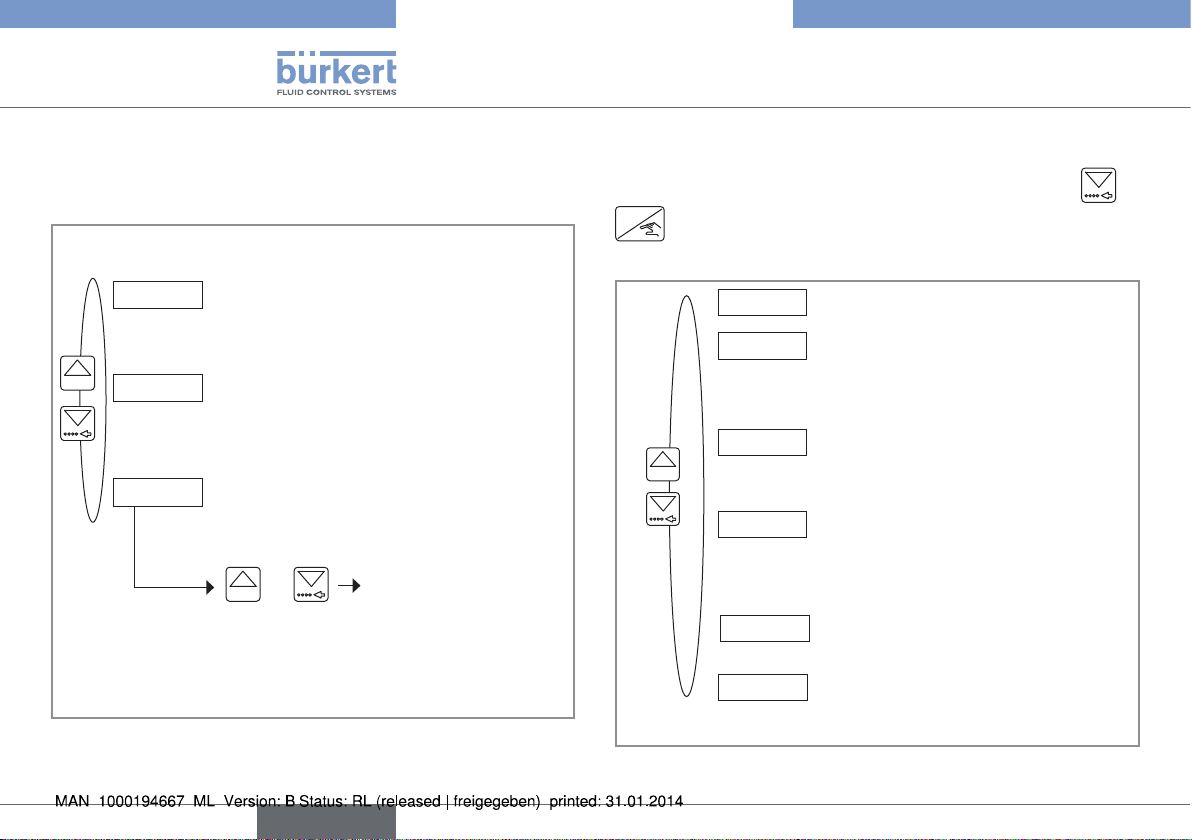
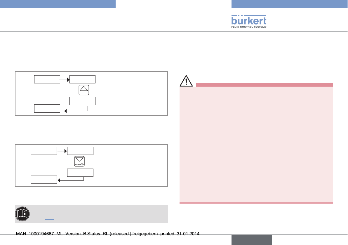
8.3. Operating levels of the device
The device has two operating levels: the Process level and the Configuration level.
The Process level makes it possible:
• to read the flow rate measured by the device and the value of the
totalizers, the main and the daily one.
• to reset the daily totalizer.
• to access the Configuration level.
The Configuration level makes it possible to set the device
parameters.
Table 4: Default settings of the device
Function Default value
LANGUAGE English
UNIT of the flow rate l/s
UNIT of the totalizers litre
Number of decimals 2
K FACTOR 46,60
FILTER Filter 2
Process level
Configuration level
12.6 l/s
87654 l
+
> 5 s
2)
231 l.
+
0......9
> 2 s
To reset the daily
totalizer (identified by
a dot after the volume
units).
2)
Possible if the ENTER key is unlocked (see chap. 8.2)
Fig. 12: Diagram of the levels of the device
Once the settings of a parameter is done if you do not want
to adjust another parameter, go to the "END" parameter of
the Configuation level and press
ENTER
to save the settings
and go back to the Process level.
lANGUAGE
UNit
K-FACtOR
FiltER
tOtAl
END
Process level
16
English
Page 19
Type 8025/8035 battery powered
Operating and commissioning
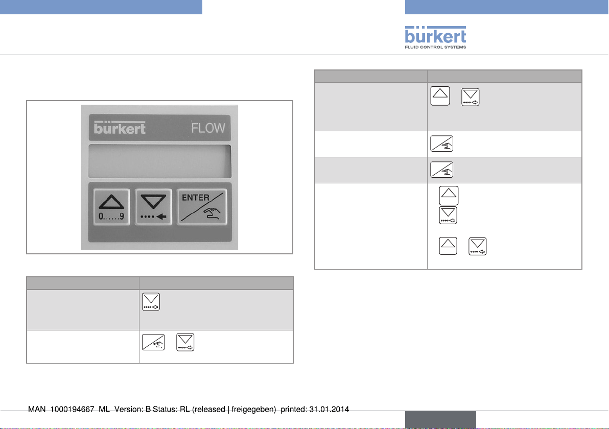
8.4. Description of the navigation
keys
Fig. 13: Foil of the device
You want to... Press...
Move in the parameters of
a level.
Access the Configuration
level.
To go to the next parameter.
ENTER
+ simultaneously for 5 s,
in the Process level
You want to... Press...
Reset the daily totalizer.
0......9
+ simultaneously for 2 s,
when the daily totalizer is displayed in
the Process level
Select the displayed
ENTER
parameter.
Confirm the displayed
ENTER
value.
Modify a numerical value.
•
0......9
•
the blinking digit.
0......9
•
point.
to increase the blinking digit.
to select the digit at the left of
+ to move the decimal
English
17
Page 20
Type 8025/8035 battery powered
Operating and commissioning
8.5. Details of the Process level
This level is active by default when the device is energized.
Value of the measured flow rate, displayed
in the unit chosen in the "UNIT" parameter of
the Configuration level.
Value of the main totalizer, total volume of
fluid counted by the device since the last
reset.
Value of the daily totalizer (identified by a
dot after the volume units), volume of fluid
counted by the device since the last reset.
0......9
+
> 2 s
Resetting the daily
totalizer.
0......9
12.6 l/s
87654 l
231 l.
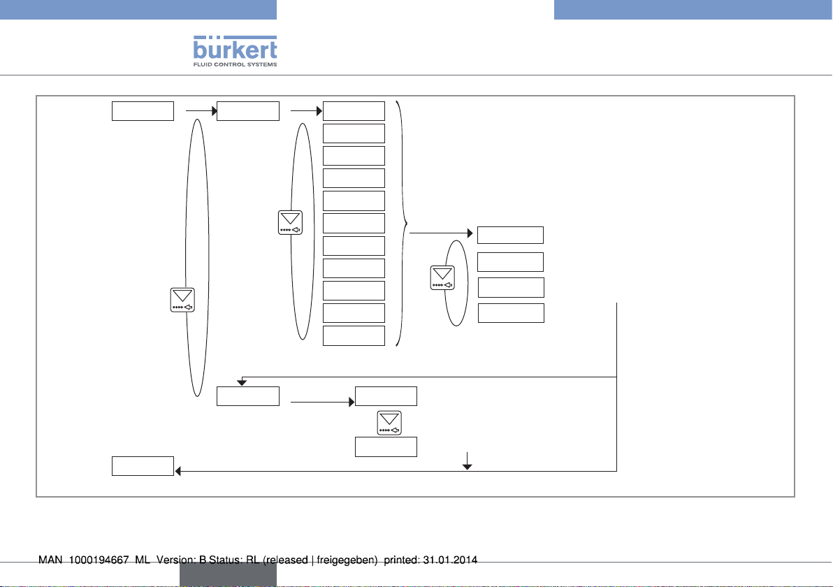
8.6. Details of the Configuration level
To access the Configuration level, simultaneously press keys
ENTER
for at least 5 s.
This level comprises the following configurable parameters:
lANGUAGE
UNit
K-FACtOR
0......9
FiltER
tOtAl
Choosing the display language
Choosing the flow rate unit, the
number of decimals and the unit
the totalizers are displayed in.
Entering the K factor of the fitting
used or have it defined through a
teach-in procedure.
Choosing the degree of attenuation
of the measured flow rate variations, with effect on the displayed
flow rate.
Resetting both totalizers.
Going back to the Process level
END
and saving the settings.
Fig. 14: Details of the Process level
18
English
Fig. 15: Diagram of the Configuration level
Page 21

Type 8025/8035 battery powered
Operating and commissioning
8.6.1. Choosing the display language
When the device is energized for the first time, the display language
is English.
lANGUAGE ENGlish
DEUtsCh
FRANçAis
itAliANO
→ Confirm the dis-
played language:
The selected language is immediately
active.
UNit
Fig. 16: Diagram of the "LANGUAGE" parameter of the
Configuration level
8.6.2. Choosing the flow rate units, the number of decimals and the units of the totalizers
The max. flow rate that can be displayed depends on the
number of decimals chosen:
• 9999 if the number of decimals = 0,
• 999,9 if the number of decimals = 1,
• 99,99 if the number of decimals = 2,
• 9,999 if the number of decimals = 3.
The maximal volume that can be displayed by the totalizers
depends on the unit of the chosen volume:
• 9 999 999 if the chosen volume unit is "litre",
3
• 999 999 if the chosen volume unit is "m
The "UNIT" parameter makes it possible to choose:
• the flow rate units.
• a fixed number of decimals (choose 0, 1, 2 or 3) to display the
flow rate in the Process level.
• the volume units of the totalizers if the unit previously chosen is in
litres or in m
3
.
", or "gallon".
English
19
Page 22
Type 8025/8035 battery powered
Operating and commissioning
UNit
FlOw RAtE
lit/sEC
lit/miN
lit/h
m3/miN
m3/h
Us GAl/s
Us GAl/m
Us GAl/h
imp GA/s
imp GA/m
GA/h
tOtAl
K-FACtOR
Fig. 17: Diagram of the "UNIT" parameter of the Configuration level
→ Choose the flow rate unit.
→ Confirm
DEC pt 0
DEC pt 1
DEC pt 2
DEC pt 3
If the chosen unit is in litres or m3.
litRE
→ Choose the totalizer unit.
→ Confirm
m3
→ Choose the number
of decimal positions.
→ Confirm
If the chosen unit
is in gallons.
20
English
Page 23
Type 8025/8035 battery powered
Operating and commissioning
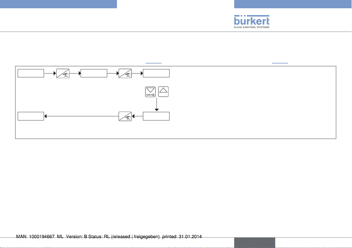
8.6.3. Entering or determining the K factor of the fitting used
The device determines the flow rate in the pipe using the fitting K factor.
The K factor of the fitting used can either be entered (see Fig. 18) or determined using a teach-in procedure (See Fig. 19).
K-FACtOR
ENTER
tEACh NO K=000.0
ENTER
The display shows the last K factor of the fitting, may it have been
entered or determined by a teach-in procedure.
→ Edit the parameter.
0......9
ENTER
Fig. 18: Entering the K factor of the fitting used
→ Enter the K factor (value between 0,0001 and 9999,9) of the
K=48.30FiltER
fitting used.
→ Confirm the displayed value.
English
21
Page 24
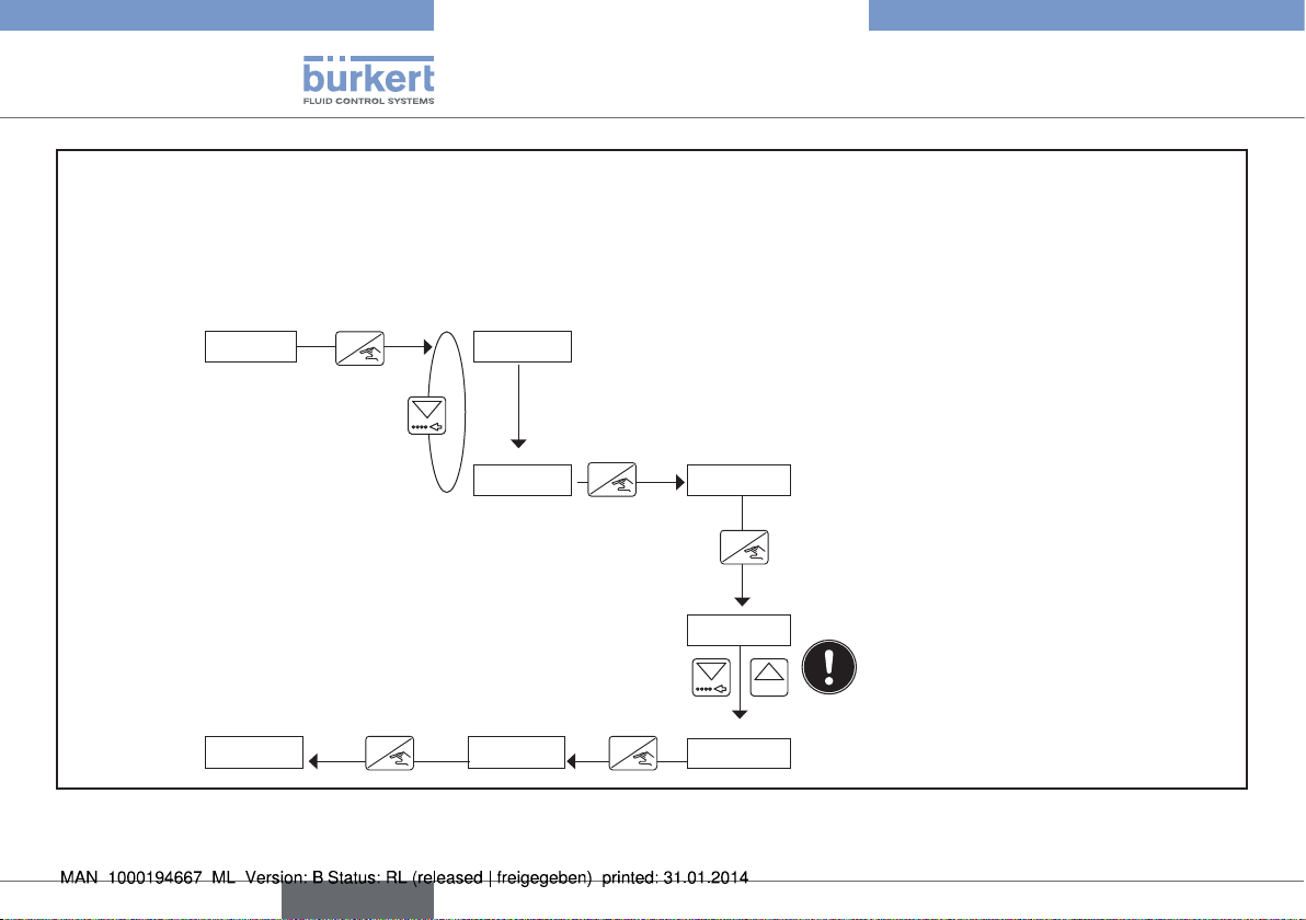
The teach-in procedure is done depending on a known volume.
→ Prepare a tank with a known volume.
→ Stop the fluid circulation.
→ confirm "TEACH Y.": "FILL END." is displayed.
Type 8025/8035 battery powered
Operating and commissioning
K-FACtOR tEACh NO
ENTER
tEACh Y Fill END
The device calculates
the K factor of the
fitting and displays it.
ENTER
Fig. 19: Teach-in procedure depending on a volume
22
English
K=48.30FiltER
ENTER
ENTER
ENTER
0000.0 l
0......9
0100.0 l
→ Charge the pipe to fill the tank.
→ When the tank is full, confirm "FILL END":
Do not enter a volume value of 0,0
because the calculated K-factor would
be of 0,0 and the device would not be
operating.
→ Enter the volume (value > 0,0 and ≤ 9999,9)
of fluid that passed in the circuit.Confirm.
Page 25
Type 8025/8035 battery powered
Maintenance and troubleshooting
8.6.4. Configuring the filter
This parameter makes it possible to dampen the fluctuations ot the
display.
Ten filters are available.
FiltER FiltER 0
→ Choose the filter.
0......9
FiltER 9
tOtAl
Fig. 20: Diagram of the "FILTER" parameter of the Configuration level
8.6.5. Resetting both totalizers
tOtAl REs NO
→ Confirm
→ Choose to reset the
two totalizers or not.
REs YEs
END
Fig. 21: Diagram of the "TOTAL" parameter of the Configuration
level
The daily totalizer can be reset from the Process level (see
chap. 8.5).
→ Confirm
9. MAINTENANCE AND TROUBLESHOOTING
9.1. Safety instructions
danger
Risk of injury due to high pressure in the installation.
• Stop the circulation of fluid, cut off the pressure and drain the
pipe before loosening the process connections.
Risk of injury due to electrical voltage.
• Shut down and isolate the electrical power source before carrying out work on the system.
• Put the power switch to OFF before carrying out work on the
device.
• Observe all applicable accident protection and safety regulations for electrical equipment.
Risk of injury due to high fluid temperatures.
• Use safety gloves to handle the device.
• Stop the circulation of fluid and drain the pipe before loosening
the process connections.
Risk of injury due to the nature of the fluid.
• Respect the prevailing regulations on accident prevention and
safety relating to the use of aggressive fluids.
English
23
Page 26
Type 8025/8035 battery powered
Maintenance and troubleshooting
Warning
Risk of injury due to non-conforming maintenance.
• Maintenance must only be carried out by qualified and skilled
staff with the appropriate tools.
• Ensure that the restart of the installation is controlled after any
interventions.
9.2. Cleaning the device
The device can be cleaned with a cloth dampened with water or a
detergent compatible with the materials the device is made of.
Please feel free to contact your Bürkert supplier for any additional
information.
9.3. Cleaning the flow sensor of the 8025
note
• Use a cleaning product that is compatible with the materials the
flow sensor is made of.
• Do not use any abrasive acting materials.
note
After cleaning of the flow sensor:
• Rinse the flow sensor.
• Check the seal and replace it if necessary.
9.4. Replacing the batteries
Dispose of the used batteries in compliance with the prevailing legislation.
→ Open the housing as indicated in Fig. 10 chap. 8.2.
→ Disconnect the flow sensor to make easier the access to the
batteries.
→ Take off the batteries connectors.
→ Replace the batteries one after the other to keep the data regis-
tered in the device.
→ Plug the connectors onto the batteries.
→ Reconnect the flow sensor.
→ Close the cover.
→ Tighten the screws.
→ Close the lid.
→ Tighten the screw.
24
English
Page 27
Type 8025/8035 battery powered
Spare parts and accessories
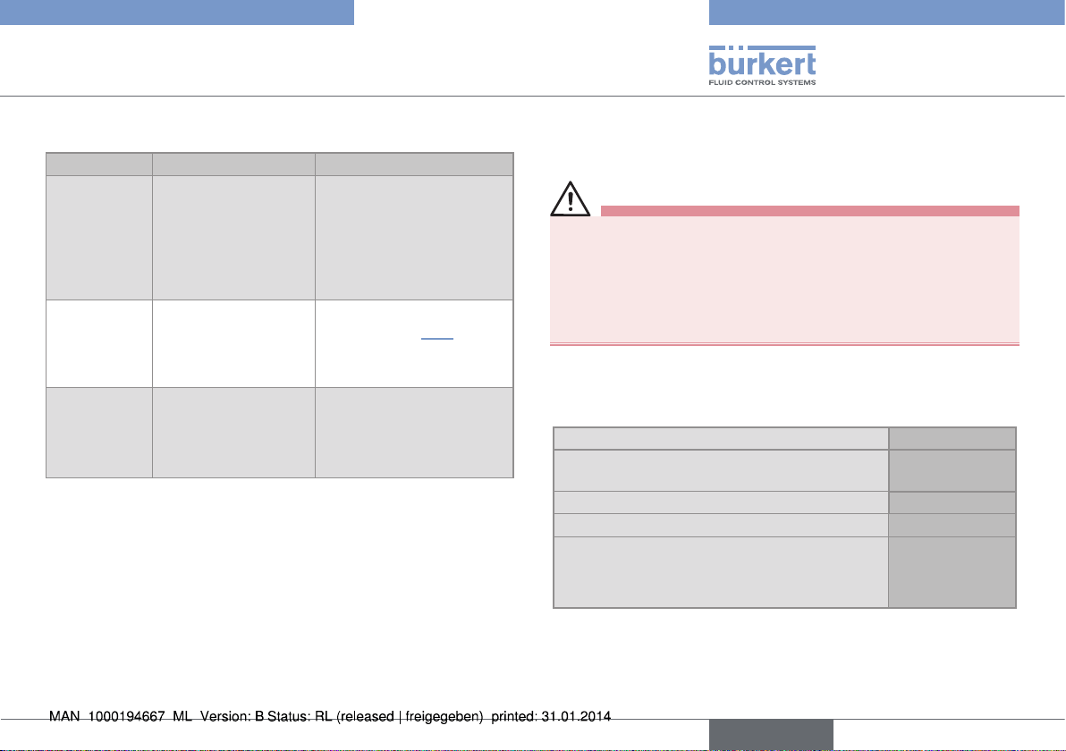
9.5. If you encounter problems
Display Possible cause Recommended action
"ERROR" The user parameters
are lost.
→ Parameterise the
device again.
→ If the message appears
repeatedly send the
device back to your
supplier.
"LOW BATT" The battery power
is too low to ensure
the operating of the
device.
Value of the
flow rate or of
the totalizer
fashes
The battery power
is getting low but
the device is still
operating.
→ Replace the batteries
(see chap. 9.4).
→ Plan to replace the
batteries
10. SPARE PARTS AND ACCESSORIES
attention
Risk of injury and/or damage caused by the use of unsuitable
parts.
Incorrect accessories and unsuitable replacement parts may
cause injuries and damage the device and the surrounding area.
• Use only original accessories and original replacement parts
from Bürkert.
10.1. SE35 electronic module
Spare part Order code
Cover in PC, with lid, incl. window, screws,
sticked foil and electronic board
Set with 8 FLOW foils 553191
Housing incl. coil as a measuring element 425247
Set including:
• 2 M20x1.5 screw plugs
• 2 flat seals
425433
444705
English
25
Page 28

Type 8025/8035 battery powered
Packaging, Transport
10.2. 8025 flowmeter-totalizer
Spare part Order code
Cover in PC, with lid, incl. window, screws,
sticked foil and electronic board
Set with 8 FLOW foils 553191
Set including:
• 2 M20x1.5 screw plugs
• 2 flat seals
Set including:
• 1 green FKM seal
• 1 black EPDM seal
Housing incl. snap ring and nut 552398
Snap ring 619205
Nut 619204
Flow sensor with coil (short sensor) for
DN ≤100 + replacement instructions
Flow sensor with coil (long sensor) for
DN ≥100 + replacement instructions
425433
444705
552111
633366
634757
11. PACKAGING, TRANSPORT
note
Damage due to transport
Transport may damage an insufficiently protected device.
• Transport the device in shock-resistant packaging and away
from humidity and dirt.
• Do not expose the device to temperatures that may exceed the
admissible storage temperature range.
12. STORAGE
note
Poor storage can damage the device.
• Store the device in a dry place away from dust.
• Storage temperature of the device: 0 to +60 °C.
26
English
Page 29

Type 8025/8035 battery powered
Packaging, Transport
13. DISPOSAL OF THE PRODUCT
Dispose of the device and its packaging in an environmentally-
→
friendly way.
note
Damage to the environment caused by products contaminated by fluids.
• Keep to the existing provisions on the subject of waste disposal
and environmental protection.
note
Comply with the national and/or local regulations which
concern the area of waste disposal.
English
27
Page 30

Type 8025/8035 battery powered
28
English
Page 31

Typ 8025 / 8035 mit Batterien
1. DIE BEDIENUNGSANLEITUNG ...............................................................3
1.1. Darstellungsmittel ............................................................................. 3
1.2. Begriffsdefinition "Gerät" ................................................................ 3
2. BESTIMMUNGSGEMÄSSE VERWENDUNG ......................................4
3. GRUNDLEGENDE SICHERHEITSHINWEISE ....................................4
4. ALLGEMEINE HINWEISE .............................................................................6
4.1. Herstelleradresse und internationale Kontaktadressen ........... 6
4.2. Gewährleistung.................................................................................6
4.3. Informationen im Internet ................................................................ 6
5. BESCHREIBUNG .............................................................................................6
5.1. Vorgesehener Einsatzbereich ........................................................ 6
5.2. Allgemeine Beschreibung .............................................................. 6
5.3. Beschreibung der Typenschilder ..................................................6
5.4. Verfügbare Ausführungen ..............................................................7
6. TECHNISCHE DATEN ...................................................................................7
6.1. Betriebsbedingungen ......................................................................7
6.2. Einhaltung von Normen und Richtlinien ...................................... 7
6.3. Allgemeine Technische Daten ....................................................... 8
6.3.1. Mechanische Daten ..............................................................8
6.3.2. Allgemeine Daten ................................................................10
7. INSTALLATION ............................................................................................... 11
7.1. Sicherheitshinweise .......................................................................11
7.2. Fluidischer Anschluss ...................................................................12
7.2.1. Installation des Fittings in die Rohrleitung .....................12
7.2.2. Installation des 8025 in ein Fitting S020 ......................14
7.2.3. Installation des Elektronikmoduls SE35 in ein
Sensor-Fitting S030 ...........................................................14
7.3. Beschreibung der Anschlüsse auf der Elektronikplatine ......14
8. BEDIENUNG UND INBETRIEBNAHME ............................................. 15
8.1. Sicherheitshinweise .......................................................................15
8.2. Einschalten des Gerätes und Blockieren / Entblocken
der ENTER-Taste ....................................................................................15
8.3. Bedienebenen des Gerätes .........................................................16
8.4. Beschreibung der Navigations-Tasten ......................................17
8.5. Details der Prozess-Ebene ..........................................................18
8.6. Details der Einstellungs-Ebene ...................................................18
8.6.1. Display-Sprache auswählen .............................................19
8.6.2. Durchflusseinheit, Dezimalstellen und Mengen-
zähler-Einheit auswählen ...................................................19
8.6.3. K-Faktor des Fittings eingeben oder bestimmen ........21
8.6.4. Filter einstellen ....................................................................23
8.6.5. Beide Mengenzähler zurückstellen ..................................23
9. WARTUNG, FEHLERBEHEBUNG ......................................................... 23
9.1. Sicherheitshinweise .......................................................................23
9.2. Reinigung des Gerätes .................................................................24
9.3. Reinigung des Durchfluss-Sensors des 8025 ........................24
9.4. Batterien wechseln ........................................................................24
deutsch
1
Page 32

9.5. Problemlösung ................................................................................25
10. ERSATZTEILE UND ZUBEHÖR...........................................................25
10.1. Elektronikmodul SE35 ................................................................25
10.2. Durchflussmessgerät-Mengenzähler 8025 ...........................26
11. VERPACKUNG, TRANSPORT ..............................................................26
12. LAGERUNG ................................................................................................... 26
13. ENTSORGUNG DES GERÄTES ..........................................................27
Typ 8025 / 8035 mit Batterien
2
deutsch
Page 33

Typ 8025 / 8035 mit Batterien
Die Bedienungsanleitung
1. DIE BEDIENUNGSANLEITUNG
Die Bedienungsanleitung beschreibt den gesamten Lebenszyklus
des Gerätes. Bewahren Sie diese Anleitung so auf, dass sie für
jeden Benutzer zugänglich ist und jedem neuen Eigentümer des
Gerätes wieder zur Verfügung steht.
Diese Bedienungsanleitung enthält wichtige Informationen
zur Sicherheit!
Das Nichtbeachten dieser Hinweise kann zu gefährlichen Situationen führen.
• Diese Bedienungsanleitung muss gelesen und verstanden
werden.
1.1. Darstellungsmittel
Gefahr!
Warnt vor einer unmittelbaren Gefahr!
• Bei Nichteinhaltung sind Tod oder schwere Verletzungen die
Folge.
WarnunG!
Warnt vor einer möglicherweise gefährlichen Situation!
• Bei Nichteinhaltung drohen schwere Verletzungen oder Tod.
VOrSIChT!
Warnt vor einer möglichen Gefährdung!
• Nichtbeachtung kann mittelschwere oder leichte Verletzungen
zur Folge haben.
hInWeIS!
Warnt vor Sachschäden!
• Bei Nichtbeachtung kann das Gerät oder die Anlage beschädigt
werden.
bezeichnet wichtige Zusatzinformationen, Tipps und
Empfehlungen.
verweist auf Informationen in dieser Bedienungsanleitung
oder in anderen Dokumentationen.
→ markiert einen Arbeitsschritt, den Sie ausführen müssen.
1.2. Begriffsdefinition "Gerät"
Der in dieser Anleitung verwendete Begriff "Gerät" steht immer für
das Durchflussmessgerät / der Mengenzähler mit Batterien Typ
8025 oder 8035.
deutsch
3
Page 34

Typ 8025 / 8035 mit Batterien
Bestimmungsgemässe Verwendung
2. BESTIMMUNGSGEMÄSSE VERWENDUNG
Bei nicht bestimmungsgemäßem Einsatz dieses Gerätes
können Gefahren für Personen, Anlagen in der Umgebung
und die Umwelt entstehen.
• Das Durchfluss-Messgerät / Der Mengenzähler mit Batterien
Typ 8025 oder 8035 dient zur Messung des Durchflusses einer
Flüssigkeit und zählt das Volumen der Flüssigkeit zusammen.
• Schützen Sie das Gerät vor elektromagnetischen Störungen, U.V.-Bestrahlung und bei Außenanwendung vor
Witterungseinflüssen.
• Für den Einsatz sind die in den Vertragsdokumenten und der
Bedienungsanleitung spezifizierten zulässigen Daten, Betriebsund Einsatzbedingungen zu beachten.
• Zum sicheren und problemlosen Einsatz des Gerätes müssen
Transport, Lagerung und Installation ordnungsgemäß erfolgen,
außerdem müssen Betrieb und Wartung sorgfältig durchgeführt
werden.
• Achten Sie immer darauf, dieses Gerät auf ordnungsgemäße
Weise zu verwenden.
→ Beachten Sie bei der Ausfuhr des Gerätes gegebenenfalls
bestehende Beschränkungen.
3. GRUNDLEGENDE SICHERHEITSHINWEISE
Diese Sicherheitshinweise berücksichtigen keine
• Zufälligkeiten und Ereignisse, die bei Montage, Betrieb und
Wartung der Geräte auftreten können.
• Ortsbezogenen Sicherheitsbestimmungen, für deren Einhaltung,
auch in Bezug auf das Installations- und Wartungspersonal, der
Betreiber verantwortlich ist.
Gefahr durch hohen Druck in der Anlage!
• Vor dem Lösen der Prozessanschlüsse die Anlage druckfrei
schalten und die Flüssigkeitszirkulation stoppen.
Gefahr durch elektrische Spannung!
• Das Gerät vor Beginn der Arbeiten auschalten (Schalter auf
OFF setzen).
• Schalten Sie vor Beginn der Arbeiten in jedem Fall die Spannung ab, und sichern Sie diese vor Wiedereinschalten!
• Beachten Sie geltende Unfallverhütungs- und Sicherheitsbestimmungen für elektrische Geräte!
Gefahr durch hohe Flüssigkeitstemperaturen!
• Das Gerät nur mit Schutzhandschuhen anfassen.
• Vor dem Lösen der Prozessanschlüsse die Flüssigkeitszirkulation stoppen und die Rohrleitung leeren.
4
deutsch
Page 35

Typ 8025 / 8035 mit Batterien
Grundlegende Sicherheitshinweise
Gefahr aufgrund der Art der Flüssigkeit!
• Beachten Sie die Regeln, die auf dem Gebiet der Unfallverhütung und der Sicherheit in Kraft sind und die sich auf die
Verwendung gefährlicher Flüssigkeiten beziehen.
Allgemeine Gefahrensituationen.
Zum Schutz vor Verletzungen ist zu beachten
• Dieses Gerät nicht für die Durchflussmessung von Gas einsetzen.
• Dieses Gerät nicht in explosionsgefährdeten Bereichen einsetzen.
• Dieses Gerät nicht in einer Umgebung verwenden, die mit den
Materialien, aus denen es besteht, inkompatibel ist.
• Keine Flüssigkeit verwenden, die sich nicht mit den Werkstoffen
verträgt, aus denen das Gerät besteht.
• Dass die Anlage nicht unbeabsichtigt betätigt werden kann.
• Belasten Sie das Gerät nicht mechanisch (z. B. durch Ablage
von Gegenständen oder als Trittstufe).
• Nehmen Sie keine äußerlichen oder innerlichen Veränderungen
am Gerät vor.
• Installations- und Instandhaltungsarbeiten dürfen nur von autorisiertem Fachpersonal mit geeignetem Werkzeug ausgeführt werden.
• Betreiben Sie das Gerät nur in einwandfreiem Zustand und
unter Beachtung der Bedienungsanleitung.
Allgemeine Gefahrensituationen.
Zum Schutz vor Verletzungen ist zu beachten
• Bei der Einsatzplanung und dem Betrieb des Gerätes die allgemeinen Regeln der Technik einhalten.
hInWeIS!
Das Gerät kann durch das Medium beschädigt werden.
• Kontrollieren Sie systematisch die chemische Verträglichkeit der
Werkstoffe, aus denen das Gerät besteht, und der Flüssigkeiten,
die mit diesem in Berührung kommen können (zum Beispiel: Alkohole, starke oder konzentrierte Säuren, Aldehyde, Basen, Ester,
aliphatische Verbindungen, Ketone, aromatische oder halogenierte Kohlenwasserstoffe, Oxidations- und chlorhaltige Mittel).
hInWeIS!
Elektrostatisch gefährdete Bauelemente / Baugruppen!
• Das Gerät enthält elektronische Bauelemente, die gegen elektrostatische Entladung (ESD) empfindlich reagieren. Berührung
mit elektrostatisch aufgeladenen Personen oder Gegenständen
gefährdet diese Bauelemente. Im schlimmsten Fall werden sie
sofort zerstört oder fallen nach der Inbetriebnahme aus.
• Beachten Sie die Anforderungen nach EN 61340 -5-1 und 5-2,
um die Möglichkeit eines Schadens durch schlagartige elektrostatische Entladung zu minimieren bzw. zu vermeiden!
• Achten Sie ebenso darauf, dass Sie elektronische Bauelemente
nicht bei anliegender Versorgungsspannung berühren!
deutsch
5
Page 36

1
2
Typ 8025 / 8035 mit Batterien
Allgemeine Hinweise
4. ALLGEMEINE HINWEISE
4.1. Herstelleradresse und internationale Kontaktadressen
Sie können mit dem Hersteller des Gerätes unter folgender Adresse
Kontakt aufnehmen:
Bürkert SAS
Rue du Giessen
BP 21
F-67220 TRIEMBACH-AU-VAL
oder wenden Sie sich an Ihr lokal zuständiges Vertriebsbüro von
Bürkert.
Die internationalen Kontaktadressen finden Sie im Internet unter:
www.burkert.com
4.2. Gewährleistung
Voraussetzung für die Gewährleistung ist der bestimmungsgemäße
Gebrauch des Gerätes unter Beachtung der im vorliegenden
Handbuch spezifizierten Einsatzbedingungen.
4.3. Informationen im Internet
Bedienungsanleitungen und Datenblätter zu den Typen 8025 oder
8035 finden Sie im Internet unter: www.buerkert.de
5. BESCHREIBUNG
5.1. Vorgesehener Einsatzbereich
Das Durchfluss-Messgerät / Der Mengenzähler mit Batterien Typ
8025 oder 8035 dient zur Messung des Durchflusses einer Flüssigkeit und zählt das Volumen der Flüssigkeit zusammen.
5.2. Allgemeine Beschreibung
Das Gerät Typ 8025 besteht aus einem Elektronikmodul mit Display
und einem Durchfluss-Sensor mit Flügelrad.
Das Gerät Typ 8035 besteht aus einem Elektronikmodul SE35 und
einem Sensor-Fitting S030 mit Flügelrad.
Das Gerät wird mit zwei Batterien versorgt.
5.3. Beschreibung der Typenschilder
1. Typ des Gerätes
TOTAL :8025- SUPPLY: BATT9V
COIL SHORT - OUT: /
S/N 1439
Made in France
00418403 W43MA
Bild 1: Typenschild des
8025
2. Betriebsspannung
3. Ausgang: Keiner
4. Herstellungscode
5. Konformitäts-Logo
457836
6. Durchfluss-Sensor-Daten
7. Seriennummer
8. Bestellnummer
6
deutsch
Page 37

1 2
Typ 8025 / 8035 mit Batterien
Technische Daten
1. Typ des Gerätes
TOTAL :SE35/8035 COIL 9V
IP65
S/N 1439
Made in France
00423921 W43MA
2. Durchfluss-Sensor-Daten
3. Betriebsspannung
4. Herstellungscode
5. Konformitäts-Logo
457836
6. Schutzart
Bild 2: Typenschild des
8035
7. Seriennummer
8. Bestellnummer
5.4. Verfügbare Ausführungen
• Der Durchflussmessgerät-Mengenzähler 8035 besteht aus einem
Elektronikmodul SE35 mit Bestell-Nummer 423921 und einem
Sensor-Fitting S030, der separat bestellt wird.
• Der Durchflussmessgerät-Mengenzähler 8025 ist in zwei Ver-
sionen verfügbar:
Typ des
Durchfluss-Sensors
kurz, mit Spule FKM
lang, mit Spule FKM
Werkstoff der
Dichtung
Bestellnummer
418403
418405
6. TECHNISCHE DATEN
6.1. Betriebsbedingungen
Temperaturbereich 0 bis +60 °C
Luftfeuchtigkeit < 80 %, nicht kondensierend
Höhe über
Meeresspiegel
Schutzart IP65, Klappe des Deckels bis zum
6.2. Einhaltung von Normen und Richtlinien
Durch folgende Normen wird die Konformität mit den EG-Richtlinien
erfüllt:
• EMV: EN 61000-6-2, EN 61000-6-3
• Niederspannungsrichtlinie: EN 61 010-1
• Vibration: EN 60068-2-6
• Schock: EN 60068-2-27
• Druck: Gemäß Artikel 3§3 der 97/23/CE Druckgeräterichtlinie.
Gemäß der 97/23/CE Druckgeräterichtlinie: Das Gerät kann nur
unter folgenden Bedingungen eingesetzt werden (abhängig vom
maximalen Druck, vom DN der Rohrleitung und von der Flüssigkeit)
max. 2000 m
Anschlag und beide Schraubstopfen
festgeschraubt.
deutsch
7
Page 38

203
Typ 8025 / 8035 mit Batterien
Technische Daten
Art der
Flüssigkeit
Voraussetzungen
8025 8035
1)
Flüssigkeitsgruppe 1
nur DN25 DN ≤ 25
Kap. 1.3.a
Flüssigkeits-
gruppe 2
Kap. 1.3.a
Flüssigkeitsgruppe 1
Kap. 1.3.b
DN ≤ 32
oder DN > 32 und
PNxDN ≤ 1000
DN ≤ 25
oder DN > 25 und
PNxDN ≤ 2000
DN ≤ 32
oder DN > 32 und
PNxDN ≤ 1000
PNxDN ≤ 2000
Flüssigkeitsgruppe 2
DN ≤ 400 DN ≤ 200
Kap. 1.3.b
1)
Für Typ 8035: Sensor-Fitting S030, DN6 bis DN65, aus PP, PVC,
PVDF, Messing oder Edelstahl.
6.3. Allgemeine Technische Daten
6.3.1. Mechanische Daten
Teil Werkstoff
Gehäuse / Dichtung PC / NBR
Deckel mit Klappe / Dichtung PC / Silikon
Frontfolie Polyester
Teil Werkstoff
M20x1,5 Schraubstopfen /
PA / Neopren
Dichtung
Schrauben Edelstahl
Überwurfmutter PC
Durchfluss-Sensor (in Kontakt mit
PVDF / FKM
der Flüssigkeit) / Dichtung (nur
8025)
Axe und Lager des Flügelrads Keramik
R=90
91
21
85.5
102
164.5
49.5
30
136
Bild 3: Abmessungen des 8025 [mm]
88
88
8
deutsch
Page 39

Typ 8025 / 8035 mit Batterien
Technische Daten
Tab. 1: Abmessung H in mm des Durchflussmessgeräts-
Mengenzählers 8025 verbunden mit einem Fitting S020
H
H
T-Ftting
AnschlussSchellen
Schweißstutzen, aus
Kunststoff
Schweißstutzen mit
Radius aus
Edelstahl
DN20 185
DN25 185
DN32 188
DN40 192 188
DN50 198 223 193
DN65 198 221 206 199
DN80 226 212 204
DN100 231 219 214
DN110 227
DN125 234 254 225
T-Ftting
AnschlussSchellen
Schweißstutzen, aus
Kunststoff
Schweißstutzen mit
Radius aus
Edelstahl
DN150 244 261 236
DN180 268
DN200 280 282 257
DN250 300 317
DN300 312 336
DN350 325 348
DN400 340
deutsch
9
Page 40

Typ 8025 / 8035 mit Batterien
Technische Daten
180
91
21
88
88
95
105
75
104
114
Bild 4: Abmessungen [mm] des Elektronikmoduls SE35
Tab. 2: Abmessung H in mm des Elektronikmoduls SE35
verbunden mit einem Sensor-Fitting S030
DN (mm) 06 08 15 20 25 32 40 50 65
H [mm] 134 134 139 137 137 140 144 151 151
1)
H
Die Höhe H ist unabhängig
von den Anschlüssen sowie
dem Werkstoff des Fittings
6.3.2. Allgemeine Daten
Typ 8025 8035
Durchmesser der
Leitungen
DN20 (außer diejenigen auf Seite
13 angegeben) bis DN400
Typ des Fittings S020 S030
Flüssigkeitstemperatur
Die Flüssigkeitstemperatur kann durch
den Druck der Flüssigkeit und den Werkstoff des verwendeten Fittings eingeschränkt sein: Siehe Bild 5 und
Flüssigkeitsdruck
Der Flüssigkeitsdruck kann durch die
Temperatur der Flüssigkeit und den
Werkstoff des verwendeten Fittings eingeschränkt sein: Siehe Bild 5
Durchflussmessung
• Messbereich
• Messfehler, mit Teach-
• 0,2 bis 10 m/s
• ±0,5 % des Messbereichsendes
In-Kalibrierverfahren
• Messfehler mit K-Faktor
des verwendeten Fittings
• Linearität
• Wiederholbarkeit
• ± (0,5% des Messbereichsendes +
2,5 % des Messwertes)
• ±0,5 % vom Messbereichsende
• ±0,4 % vom Messwert
Versorgungsspannung Zwei 9 V-Batterien (6LR61)
Mindest-Autonomie: 1 Jahr bei 20° C
1)
Unter folgenden Referenzbedingungen bestimmt: Flüssigkeit
= Wasser, Temperatur des Wassers und der Umgebung =
20 °C, Mindestein- und -auslaufstrecken eingehalten, passende
Rohrdurchmesser.
DN6 bis
DN65
1)
1)
10
deutsch
Page 41

11
Typ 8025 / 8035 mit Batterien
Installation
P Flüssigkeit (bar)
10
9
8
7
6
5
4
3
2
1
0
Verwendungsbereich
Metall
PVDF
PVC + PP
PVC (PN10)
-15 0 +20 +40+60
PVDF (PN10)
PP (PN10)
+80
T Flüssigkeit (°C)
Bild 5: Druck-Temperatur-Abhängigkeitskurven der Flüssigkeit für
den 8025, je nach Werkstoff des Fittings S020
Verwendungsbereich
A
Metall
PVDF
PVC + PP
PVC (PN10)
PP (PN10)
-10 +10 +30 +50+70 +90 +110
PVDF (PN10)
P Flüssigkeit (bar)
16
15
14
13
12
11
10
9
8
7
6
5
4
3
2
1
0
-30
T Flüssigkeit (°C)
7. INSTALLATION
7.1. Sicherheitshinweise
Gefahr!
Verletzungsgefahr durch hohen Druck in der Anlage!
• Vor dem Lösen der Prozessanschlüsse die Anlage druckfrei
schalten, die Flüssigkeitszirkulation stoppen und die Rohrleitung
leer laufen lassen.
Verletzungsgefahr durch Stromschlag!
• Schalten Sie vor Beginn der Arbeiten in jedem Fall die Spannung ab, und sichern Sie diese vor Wiedereinschalten!
• Das Gerät vor Beginn der Arbeiten auschalten (Schalter auf
OFF setzen).
• Beachten Sie geltende Unfallverhütungs- und Sicherheitsbestimmungen für elektrische Geräte!
Verletzungsgefahr durch hohe Flüssigkeitstemperaturen!
• Das Gerät nur mit Schutzhandschuhen anfassen.
• Vor dem Lösen
keitszirkulation stoppen und die Rohrleitung leeren.
Verletzungsgefahr aufgrund der Art der Flüssigkeit!
• Beachten Sie die Regeln, die auf dem Gebiet der Unfallverhütung
und der Sicherheit in Kraft sind und die sich auf die Verwendung
gefährlicher Flüssigkeiten beziehen.
der Prozessanschlüsse die Flüssig-
Bild 6: Druck-Temperatur-Abhängigkeitskurven der Flüssigkeit für
den 8035, je nach Werkstoff des Sensor-Fittings S030
deutsch
11
Page 42

WarnunG!
Verletzungsgefahr bei unsachgemäßer Installation!
• Fluidische Installation darf nur durch autorisiertes Fachpersonal
und mit geeignetem Werkzeug durchgeführt werden!
• Beachten Sie die Montageanweisungen des verwendeten Fittings.
Verletzungsgefahr durch ungewolltes Einschalten der Anlage
und unkontrollierten Wiederanlauf!
• Anlage vor unbeabsichtigtem Betätigen sichern.
• Nach jedem Eingriff an der Anlage einen kontrollierten Wiederanlauf gewährleisten.
Schützen Sie das Gerät vor elektromagnetischen Störungen, U.V.-Bestrahlung und bei Außenanwendung vor
Witterungseinflüssen.
7.2. Fluidischer Anschluss
Gefahr!
Verletzungsgefahr durch hohen Druck in der Anlage!
• Vor dem Lösen der Prozessanschlüsse die Anlage druckfrei
schalten, die Flüssigkeitszirkulation stoppen und die Rohrleitung
leer laufen lassen.
Verletzungsgefahr aufgrund der Art der Flüssigkeit!
• Beachten Sie die Regeln, die auf dem Gebiet der Unfallverhütung
und der Sicherheit in Kraft sind und die sich auf die Verwendung
gefährlicher Flüssigkeiten beziehen.
Typ 8025 / 8035 mit Batterien
Installation
Der Durchflussmessgerät-Mengenzähler 8025 wird in ein auf der
Rohrleitung montiertes Fitting S020 eingesteckt.
Das Elektronikmodul SE35 wird in ein auf der Rohrleitung montiertes
Sensor-Fitting S030 eingesteckt.
7.2.1. Installation des Fittings in die Rohrleitung
→ Das Fitting S020 oder Sensor-Fitting S030 so auswählen, das
der Flüssigkeitsgeschwindigkeit in der Rohrleitung geeignet ist.
Siehe folgende Diagramme.
→ Das Fitting oder Sensor-Fitting gemäß der Bedienungsanleitung
des verwendeten Fittings in die Rohrleitung einbauen.
12
deutsch
Page 43

gpm
Typ 8025 / 8035 mit Batterien
Installation
Tab. 3: Diagramme Durchfluss/ Flüssigkeitsgeschwindigkeit/ DN der Fittings S020 (links) und der Sensor-Fittings S030 (rechts)
Beispiel: Bei einem Nenndurchfluss = 10 m3/h und eine optimale Fließgeschwindigkeit zwischen 2 und 3 m/s,
→ einen DN40 (oder DN50 für (*) genannte Fittings) Fitting verwenden.
US gpm
20000
10000
5000
2000
1000
500
200
100
50
20
10
5
2
1
0.5
0.2
0.1
0.05
Durchfluss
l/min
100000
50000
30000
20000
10000
5000
3000
2000
1000
500
200
100
50
20
10
5
2
1
0.5
0.2
3
/h
m
5000
2000
1000
500
200
100
50
20
10
5
2
1
0.5
0.2
0.1
0.05
0.02
0.01
0.10.3 0.51 35 10
0.30.5 13510
Fließgeschwindigkeit
DN 400
DN 350
DN 300
DN 250
DN 200
DN 150
DN 125
DN 100
DN 80
DN 65
DN 50 (DN65)*
DN 40 (DN50)*
DN 32 (DN40)*
DN 25 (DN32)*
DN 20 (DN25)*
Beispiel
m/s
30
fps
Durchfluss
m3/h
l/min
2000
1000
500
200
100
50
20
10
0.5
0.2
0.1
0.05
500
5000
200
2000
100
1000
50
500
20
200
10
100
5
50
2
20
5
2
1
1
10
0.5
5
3
0.2
2
0.1
1
0.05
0.5
0.02
0.3
0.2
0.01
0.1 0.2 0.3 0.5 1235 10
0.3 0.5 1235 10 20 30
Fließgeschwindigkeit
DN 65
(DN65)*
DN 50
DN 40
(DN50)*
DN 32
DN 25
(DN32)*
DN 20
(DN25)*
DN 15
(DN15 / DN20)*
DN 08
DN 06
m/s
fps
(DN40)*
* Für die Fittings
• mit Außengewinde-Anschlüssen nach SMS 1145,
• mit Schweißstutzen-Anschlüssen nach SMS 3008, BS 4825 / ASME BPE oder DIN 11850 Reihe2,
• Clamp nach SMS 3017 / ISO 2852, BS 4825 / ASME BPE oder DIN 32676
1)
Das Gerät nicht in die vorgenannten DN20 Fittings einbauen.
deutsch
13
Page 44

2
1
3
4
5
6
1
2
3
Typ 8025 / 8035 mit Batterien
Installation
7.2.2. Installation des 8025 in ein Fitting S020
→ Überwurfmutter 3 auf Fitting 5 setzen.
→ Sprengring 2 in Rille 4 befestigen.
→ Prüfen, dass Dichtung 6 richtig auf dem
Durchfluss-Sensor sitzt.
→ Gerät 1 vorsichtig ins Fitting einsetzen.
Bei korrektem Einbau darf sich das Gerät nicht
drehen lassen.
→ Einheit mit Überwurfmutter 3 verriegeln, diese
nur mit der Hand festziehen.
Bild 7: Installation des 8025 in ein Fitting S020
7.2.3. Installation des Elektronikmoduls SE35 in ein Sensor-Fitting S030
→ Elektronikmodul 2 in Sensor-Fitting
S030 einsetzen.
→ Mit einer 30°-Drehung im Uhrzei-
gersinn befestigen.
→ Seitenschraube 3 festziehen, um das
Elektronikmodul an das Sensor-Fitting
befestigen.
Bild 8: Installation des Elektronikmoduls SE35 in ein Sensor-Fitting
14
S030
deutsch
7.3. Beschreibung der Anschlüsse auf der Elektronikplatine
Klemmleiste:
+: positive Stromversorgung
(rote Ader)
-: negative Stromversorgung
(schwarze Ader)
Stecker: Anschluss des
Durchfluss-Sensors
OFF ON
Klemmleiste
Stecker
Bild 9: Anschlüsse auf der
Elektronikplatine
Page 45

Typ 8025 / 8035 mit Batterien
Bedienung und Inbetriebnahme
8. BEDIENUNG UND INBETRIEBNAHME
8.1. Sicherheitshinweise
WarnunG!
Verletzungsgefahr bei unsachgemäßer Bedienung!
Nicht sachgemäße Bedienung kann zu Verletzungen, sowie
Schäden am Gerät und seiner Umgebung führen.
• Das Bedienpersonal muss den Inhalt der Bedienungsanleitung
kennen und verstanden haben.
• Besonders zu beachten sind die Sicherheitshinweise und die
bestimmungsgemäße Verwendung.
• Das Gerät/die Anlage darf nur durch ausreichend geschultes
Personal bedient werden.
WarnunG!
Verletzungsgefahr bei unsachgemäßer Inbetriebnahme!
Nicht sachgemäßer Betrieb kann zu Verletzungen sowie Schäden
am Gerät und seiner Umgebung führen.
• Vor der Inbetriebnahme muss gewährleistet sein, dass der Inhalt
der Bedienungsanleitung dem Bedienungspersonal bekannt ist
und vollständig verstanden wurde.
• Besonders zu beachten sind die Sicherheitshinweise und die
bestimmungsgemäße Verwendung.
• Das Gerät/die Anlage darf nur durch ausreichend geschultes
Personal in Betrieb genommen werden.
8.2. Einschalten des Gerätes und Blockieren / Entblocken der ENTER-Taste
→ Schraube lösen und Klappe
öffnen
→ Die 4 Schrauben lösen
dann Gehäuse-Deckel
abnehmen.
Das Gerät unter Spannung
setzen
Schalter 1
OFF ON
Schalter 2: Siehe
Bild 11
→ Schalter 1 auf ON setzen.
Bild 10: Elektronikplatine
ENTER-Taste entblockt
Bild 11: Blockieren / Entblocken der ENTER-Taste
ENTER-Taste
blockiert
deutsch
15
Page 46

ENTER
Typ 8025 / 8035 mit Batterien
Bedienung und Inbetriebnahme
8.3. Bedienebenen des Gerätes
Das Gerät verfügt über zwei Bedienebenen: Die Prozess-Ebene und
die Einstellungs-Ebene.
Die Prozess-Ebene ermöglicht es,
• den durch das Gerät gemessene Durchfluss und die Werte der
Tages- und Haupt-Mengenzähler abzulesen.
• den Tages-Mengenzähler zurück zu setzen.
• auf die Einstellungs-Ebene zu wechseln.
Die Einstellungs-Ebene ermöglicht die Einstellung der Parameter
des Gerätes.
Tab. 4: Grundeinstellungen des Gerätes
Funktion Grundeinstellung
SPRACHE English
EINHEIT des Durchflusses l/s
EINHEIT der Mengenzähler Liter
Dezimalstellen 2
K-FAKTOR 46,60
FILTER Filter 2
Prozess-Ebene
Einstellungs-Ebene
12.6 l/s
87654 l
+
> 5 s
2)
231 l.
+
0......9
> 2 s
Zurücksetzen des Tageszählers (durch den Punkt
nach der Volumen-Einheit
Prozess-Ebene
erkennbar).
2)
Wenn die ENTER-Taste entblockt ist (siehe Kap. 8.2)
Bild 12: Diagramm der Bedienebenen des Gerätes
Wenn ein Parameter eingestellt wurde und kein weiterer
Parameter geändert werden soll, zur Funktion "ENDE" des
Parametriermenüs gehen und die Taste
ENTER
um die Einstellungen zu speichern und zur Prozess-Ebene
zurück zu gehen.
sPRACHE
EinHEit
K-FAKtOR
FiltER
tOtAl
EndE
drücken,
16
deutsch
Page 47

Typ 8025 / 8035 mit Batterien
Bedienung und Inbetriebnahme
8.4. Beschreibung der
Navigations-Tasten
Bild 13: Folie des Gerätes
Sie wollen... Drücken Sie...
sich in den Funktionen
einer Ebene bewegen.
auf die Einstellungs-Ebene
wechseln.
nächste Funktion:
ENTER
+ gleichzeitig für 5 s in
der Prozess-Ebene.
Sie wollen... Drücken Sie...
den Tageszähler
zurücksetzen.
0......9
+ gleichzeitig für 2 s,
wenn der Tages-Mengenzähler in der
Prozess-Ebene angezeigt wird.
die angezeigte Funktion
ENTER
auswählen.
den angezeigten Wert
ENTER
bestätigen.
einen numerischen Wert
zum Erhöhen der ausgewählten
•
ändern.
0......9
Ziffer.
zur Auswahl der vorherigen
•
Ziffer.
0......9
+ zur Verschiebung des
•
Kommas.
.
deutsch
17
Page 48

Typ 8025 / 8035 mit Batterien
Bedienung und Inbetriebnahme
8.5. Details der Prozess-Ebene
Beim Einschalten des Gerätes ist diese Ebene aktiv.
Durchfluss-Messwert, in der in der Funktion
"EINHEIT" des Parametriermenüs ausgewählten Einheit.
Haupt-Mengenzähler-Wert, durch das Gerät
gezähltes Flüssigkeits-Volumen seit der
letzten Zurückstellung des Mengenzählers.
Tages-Mengenzähler-Wert (durch den Punkt
nach der Volumeneinheit erkennbar), Flüssigkeits-Volumen seit der letzten Zurückstellung des Mengenzählers.
0......9
+
> 2 s
Zurücksetzen des
Tages-Mengenzählers.
0......9
12.6 l/s
87654 l
231 l.
8.6. Details der Einstellungs-Ebene
ENTER
Für den Zugriff auf die Einstellungs-Ebene die Tasten
mehr als 5 s gleichzeitig drücken.
Diese Ebene erlaubt es, folgende Geräte-Parameter einzustellen:
sPRACHE
EinHEit
K-FAKtOR
0......9
FiltER
tOtAl
EndE
Display-Sprache auswählen.
Durchfluss-Einheit, Dezimalstellen
und Einheit zur Anzeige der Mengenzähler auswählen.
K-Faktor des verwendeten Fittings
eingeben oder mittels einer TeachIn-Kalibrierung ermitteln.
Filter des gemessenen Durchflusses auswählen, mit Effekt auf
den angezeigten Durchfluss.
Beide Mengenzähler zurücksetzen.
Zur Prozess-Ebene zurückgehen
und die Einstellungen speichern.
Bild 14: Details der Prozess-Ebene
18
Bild 15: Details der Einstellungs-Ebene
deutsch
Page 49

Typ 8025 / 8035 mit Batterien
Bedienung und Inbetriebnahme
8.6.1. Display-Sprache auswählen
Beim ersten Einschalten ist die Display-Sprache Englisch.
lAnGuAGE EnGlisH
dEutsCH
FRAnçAis
itAliAnO
→ Die angezeigte
Sprache bestätigen:
Die ausgewählte
Sprache ist sofort
aktiv.
EinHEit
Bild 16: Diagramm des Parameters "SPRACHE" der
Einstellungs-Ebene
8.6.2. Durchflusseinheit, Dezimalstellen und Mengenzähler-Einheit auswählen
Der maximale anzeigbare Durchflusswert hängt von den
ausgewählten Dezimalstellen ab:
• 9999 bei Dezimalstellen = 0,
• 999,9 bei Dezimalstellen = 1,
• 99,99 bei Dezimalstellen = 2,
• 9,999 bei Dezimalstellen = 3.
Der maximale Volumenwert, der durch die Mengenzähler
angezeigt werden kann, hängt von der ausgewählten Volumeneinheit ab:
• 9 999 999 bei Volumeneinheit "Liter",
3
• 999 999 bei Volumeneinheit "m
Die Funktion "EINHEIT" ermöglicht es Folgendes auszuwählen:
• Die Durchflusseinheit.
• Einen Festpunkt (Auswahl 0, 1, 2 oder 3) zur Anzeige des Durch-
flusswertes in der Prozess-Ebene.
• Die Volumeneinheit der Mengenzähler, wenn die oben ausge-
wählte Durchflusseinheit Liter oder m
" oder "gallon".
3
ist.
deutsch
19
Page 50

Typ 8025 / 8035 mit Batterien
Bedienung und Inbetriebnahme
EinHEit
duRCHFlu.
tOtAl
K-FACtOR
Bild 17: Diagramm des Parameters "EINHEIT" der
Einstellungs-Ebene
lit/sEC
lit/min
lit/H
m3/min
m3/H
us GAl/s
us GAl/m
us GAl/H
imP GA/s
imP GA/m
imP GA/H
Wenn die ausgewählte Einheit in Liter oder m3 ist.
→ Durchflusseinheit
auswählen
→ Bestätigen.
litER
→ Mengenzählereinheit
KOmmA 0
KOmmA 1
KOmmA 2
KOmmA 3
auswählen.
→ Dezimalstellen
auswählen.
→ Bestätigen.
→ Bestätigen.
m3
Wenn die ausgewählte Einheit in
Gallonen ist.
20
deutsch
Page 51

Typ 8025 / 8035 mit Batterien
Bedienung und Inbetriebnahme
8.6.3. K-Faktor des Fittings eingeben oder bestimmen
Das Gerät berechnet den Durchfluss der Flüssigkeit in der Rohrleitung mittels des K-Faktors des Fittings.
Der K-Faktor des verwendeten Fittings kann eingegeben (siehe Bild 18) oder mittels eines Teach-In-Verfahren bestimmt werden (siehe Bild
19).
K-FACtOR
ENTER
tEACH n K=000.0
ENTER
Das Display zeigt den K-Faktor des Fittings an, ob eingegeben oder
mittels Teach-In bestimmt.
→ Parameter bestätigen.
0......9
ENTER
Bild 18: Eingabe des K-Faktors des verwendeten Fittings
→ K-Faktor (Wert zwischen 0,0001 und 9999,9) des verwendeten
K=48.30FiltER
Fittings einstellen.
→ Den angezeigten Wert bestätigen.
deutsch
21
Page 52

Das Teach-In wird in Bezug auf ein bekanntes Volumen durchgeführt.
→ Einen Behälter von bekannten Volumen vorbereiten.
→ Die Flüssigkeitszirkulation stoppen.
→ "TEACH J" bestätigen: "ABF ENDE" wird angezeigt.
Typ 8025 / 8035 mit Batterien
Bedienung und Inbetriebnahme
K-FAKtOR tEACH n
ENTER
tEACH J ABF EndE
Das Gerät rechnet den
K-Faktor des Fittings
ENTER
Bild 19: Teach-In-Verfahren in Bezug auf ein Volumen
22
und zeigt ihn an.
K=48.30FiltER
deutsch
ENTER
ENTER
ENTER
0000.0 l
0......9
0100.0 l
→ Den Durchfluss in der Rohrleitung zum Füllen
des Behälters starten.
→ Wenn der Behälter voll ist, "ABF ENDE"
bestätigen.
Für den Volumenwert nicht 0,0 eingeben, weil der berechneter K-Faktor
gleich 0,0 wäre und das Gerät würde
nicht funktionieren.
→ Flüssigkeitsvolumen (Wert > 0,0 und ≤
9999,9) das durch das Gerät geflossen ist,
eingeben. Bestätigen.
Page 53

Typ 8025 / 8035 mit Batterien
Wartung, Fehlerbehebung
8.6.4. Filter einstellen
Diese Funktion ermöglicht die Schwankungen des Displays zu
dämpfen.
Zehn Filter sind verfügbar.
FiltER FiltER 0
0......9
→ Den gewünschten
Filter auswählen.
→ Bestätigen.
FiltER 9
tOtAl
Bild 20: Diagramm der Funktion "FILTER" des Parametriermenüs
8.6.5. Beide Mengenzähler zurückstellen
tOtAl REs nEin
REs JA
EndE
Bild 21: Diagramm der Funktion "TOTAL" des Parametriermenüs
Der Tages-Mengenzähler kann von der Prozess-Ebene aus
zurückgesetzt werden (siehe Kap. 8.5).
→ Die beiden Mengen-
zähler zurücksetzen
oder nicht.
→ Bestätigen.
9. WARTUNG, FEHLERBEHEBUNG
9.1. Sicherheitshinweise
Gefahr!
Verletzungsgefahr durch hohen Druck in der Anlage!
• Vor dem Lösen der Prozessanschlüsse die Anlage druckfrei
schalten und die Flüssigkeitszirkulation stoppen.
Verletzungsgefahr durch Stromschlag!
• Schalten Sie vor Beginn der Arbeiten in jedem Fall die Spannung ab, und sichern Sie diese vor Wiedereinschalten!
• Das Gerät vor Beginn der Arbeiten auschalten (Schalter auf
OFF setzen).
• Beachten Sie geltende Unfallverhütungs- und Sicherheitsbestimmungen für elektrische Geräte!
Verletzungsgefahr durch hohe Flüssigkeitstemperaturen!
• Das Gerät nur mit Schutzhandschuhen anfassen.
• Vor dem Lösen der Prozessanschlüsse die Flüssigkeitszirkulation stoppen und die Rohrleitung leeren.
Verletzungsgefahr aufgrund der Art der Flüssigkeit!
• Beachten Sie die Regeln, die auf dem Gebiet der Unfallverhütung
und der Sicherheit in Kraft sind und die sich auf die Verwendung
gefährlicher Flüssigkeiten beziehen.
deutsch
23
Page 54

Typ 8025 / 8035 mit Batterien
Wartung, Fehlerbehebung
WarnunG!
Verletzungsgefahr bei unsachgemäßer Wartung!
• Wartungsarbeiten dürfen nur durch autorisiertes Fachpersonal
und mit geeignetem Werkzeug durchgeführt werden!
• Nach einer Unterbrechung der elektrischen Versorgung ist ein
definierter und kontrollierter Wiederanlauf des Prozesses zu
gewährleisten.
9.2. Reinigung des Gerätes
Das Gerät nur mit einem Tuch oder Lappen reinigen, der leicht mit
Wasser oder mit einem Mittel befeuchtet ist, das sich mit den Werkstoffen des Gerätes verträgt.
Für weitere Auskünfte steht Ihnen Bürkert zur Verfügung.
9.3. Reinigung des DurchflussSensors des 8025
hInWeIS!
• Verwenden Sie immer ein Reinigungsmittel, das sich mit den
Materialien verträgt, aus denen der Durchfluss-Sensor besteht.
• Keine Scheuermittel verwenden.
hInWeIS!
Nach dem Reinigen des Durchfluss-Sensors:
• Den Durchfluss-Sensor spülen.
• Die Dichtung überprüfen und gegebenenfalls austauschen.
9.4. Batterien wechseln
Beachten Sie die nationalen Abfallbeseitigungsvorschriften
für die Entsorgung der verbrauchten Batterien.
→ Gehäuse gemäß Bild 10 Kap. 8.2 öffnen.
→ Durchfluss-Sensor-Kabel vom Stecker ausziehen, um leicht an
die Batterien zu gelangen.
→ Anschlüsse der Batterien trennen.
→ Batterien eine nach der anderen wechseln, um die im Gerät
gespeicherte Daten zu bewahren.
→ Anschlüsse der Batterien einstecken.
→ Den Durchfluss-Sensor-Stecker zurückschalten.
→ Den Deckel schließen.
→ Schrauben festziehen.
→ Klappe schließen.
→ Schraube festziehen.
24
deutsch
Page 55

Typ 8025 / 8035 mit Batterien
Ersatzteile und Zubehör
9.5. Problemlösung
Anzeige Bedeutung Maßnahme
"FEHLER" Benutzer-Einstel-
lungen sind verloren
gegangen.
"LOW BATT" Batterien sind
zu schwach, um
das Gerät weiter
betreiben zu können.
DurchflussWert oder
Mengenzähler-Wert
blinkt.
Batterien werden
schwach, Gerät funktioniert weiter.
→ Gerät neu einstellen.
→ Sollte diese Meldung
öfters angezeigt
werden, schicken Sie
das Gerät an Ihren
Händler zurück.
→ Batterien wechseln
(siehe Kap. 9.4).
→ Batterien sobald wie
möglich wechseln.
10. ERSATZTEILE UND ZUBEHÖR
VOrSIChT!
Verletzungsgefahr, Sachschäden durch ungeeignete Teile!
Falsches Zubehör und ungeeignete Ersatzteile können Verletzungen und Schäden am Gerät und dessen Umgebung
verursachen.
• Verwenden Sie nur Originalzubehör sowie Originalersatzteile
der Fa. Bürkert.
10.1. Elektronikmodul SE35
Ersatzteil Bestellnummer
Deckel mit Klappe, aus PC, Frontfolie, Fenster,
Schrauben und Elektronikplatine
Satz mit 8 FLOW-Folien 553191
Gehäuse mit Messelement Spule 425247
Satz mit:
• 2 M20x1,5 Schraubstopfen
• 2 Flachdichtungen
425433
444705
deutsch
25
Page 56

Typ 8025 / 8035 mit Batterien
Verpackung, Transport
10.2. DurchflussmessgerätMengenzähler 8025
Ersatzteil Bestellnummer
Deckel mit Klappe, aus PC, Frontfolie, Fenster,
Schrauben und Elektronikplatine
Satz mit 8 FLOW-Folien 553191
Satz mit:
• 2 M20x1,5 Schraubstopfen
• 2 Flachdichtungen
Satz mit:
• 1 grüne Dichtung aus FKM
• 1 schwarze Dichtung aus EPDM
Gehäuse mit Sprengring und Überwurfmutter 552398
Sprengring 619205
Überwurfmutter 619204
Durchfluss-Sensor mit Spule (kurze Aus-
führung) für DN ≤ 100 + Austauschanleitung
Durchfluss-Sensor mit Spule (lange Aus-
führung) für DN ≥100+ Austauschanleitung
425433
444705
552111
633366
634757
11. VERPACKUNG, TRANSPORT
hInWeIS!
Transportschäden!
Ein unzureichend geschütztes Gerät kann durch den Transport
beschädigt werden.
• Transportieren Sie das Gerät vor Nässe und Schmutz geschützt
in einer stoßfesten Verpackung.
• Das Gerät keinen Temperaturen außerhalb des zulässigen Temperaturbereichs für die Lagerung aussetzen.
12. LAGERUNG
hInWeIS!
Falsche Lagerung kann Schäden am Gerät verursachen!
• Lagern Sie das Gerät trocken und staubfrei!
• Lagertemperatur des Gerätes: 0 bis +60 °C.
26
deutsch
Page 57

Typ 8025 / 8035 mit Batterien
Verpackung, Transport
13. ENTSORGUNG DES GERÄTES
Entsorgen Sie das Gerät und die Verpackung umweltgerecht.
→
hInWeIS!
Umweltschäden durch Teile, die durch Flüssigkeiten kontaminiert wurden!
• Geltende Entsorgungsvorschriften und Umweltbestimmungen
einhalten!
Hinweis!
Beachten Sie die nationalen Abfallbeseitigungsvorschriften.
deutsch
27
Page 58

Typ 8025 / 8035 mit Batterien
28
deutsch
Page 59

Type 8025 / 8035 à piles
1. À PROPOS DE CE MANUEL ......................................................................3
1.1. Symboles utilisés .............................................................................. 3
1.2. Définition du terme "appareil" ........................................................ 3
2. UTILISATION CONFORME..........................................................................4
3. CONSIGNES DE SÉCURITÉ DE BASE ................................................4
4. INFORMATIONS GÉNÉRALES ..................................................................6
4.1. Adresse du fabricant et contacts internationaux.......................6
4.2. Conditions de garantie....................................................................6
4.3. Informations sur internet ................................................................. 6
5. DESCRIPTION ...................................................................................................6
5.1. Secteur d’application ......................................................................6
5.2. Description générale .......................................................................6
5.3. Description des étiquettes d’identification .................................6
5.4. Versions disponibles ........................................................................7
6. CARACTÉRISTIQUES TECHNIQUES ...................................................7
6.1. Conditions d’utilisation....................................................................7
6.2. Conformité aux normes et directives ........................................... 7
6.3. Caractéristiques techniques générales ......................................8
6.3.1. Caractéristiques mécaniques ............................................. 8
6.3.2. Caractéristiques générales ...............................................10
7. INSTALLATION ............................................................................................... 11
7.1. Consignes de sécurité ..................................................................11
7.2. Installation sur la canalisation ......................................................12
7.2.1. Installation du raccord sur la conduite ...........................12
7.2.2. Installation du 8025 sur le raccord S020 .....................14
7.2.3. Installation du module électronique SE35 sur le
raccord-capteur S030 .......................................................14
7.3. Description des connexions de la carte électronique ............14
8. RÉGLAGE ET MISE EN SERVICE ........................................................15
8.1. Consignes de sécurité ..................................................................15
8.2. Mise sous tension de l’appareil et verrouillage/déver-
rouillage de la touche ENTER .............................................................15
8.3. Niveaux d’utilisation de l’appareil ................................................16
8.4. Description des touches de navigation .....................................17
8.5. Détails du niveau Process ............................................................18
8.6. Détails du niveau Configuration ..................................................18
8.6.1. Choisir la langue d’affichage ............................................19
8.6.2. Choisir l'unité du débit, le nombre de décimales
et l’unité des totalisateurs .................................................19
8.6.3. Saisir ou déterminer le facteur K du raccord ...............21
8.6.4. Configurer le filtre ..............................................................23
8.6.5. Remettre les deux totalisateurs à zéro ...........................23
9. MAINTENANCE ET DÉPANNAGE ........................................................ 23
9.1. Consignes de sécurité ..................................................................23
9.2. Entretien de l’appareil ...................................................................24
9.3. Entretien du capteur de débit pour le 8025 ............................24
9.4. Remplacement des piles ..............................................................24
français
1
Page 60

9.5. En cas de problème .......................................................................25
10. PIÈCES DE RECHANGE ET ACCESSOIRES ...............................25
10.1. Module électronique SE35 ........................................................25
10.2. Débitmètre-totalisateur 8025 ....................................................26
11. EMBALLAGE ET TRANSPORT ............................................................26
12. STOCKAGE ................................................................................................... 26
13. ÉLIMINATION DE L’APPAREIL .............................................................27
Type 8025 / 8035 à piles
2
français
Page 61

Type 8025 / 8035 à piles
À propos de ce manuel
1. À PROPOS DE CE MANUEL
Ce manuel décrit le cycle de vie complet de l’appareil. Conservez-le
de sorte qu’il soit accessible à tout utilisateur et à disposition de tout
nouveau propriétaire.
Ce manuel contient des informations importantes relatives à
la sécurité.
Le non-respect de ces consignes peut entraîner des situations
dangereuses.
• Ce manuel doit être lu et compris.
1.1. Symboles utilisés
danger
Met en garde contre un danger imminent.
• Son non-respect peut entraîner la mort ou de graves blessures.
avertissement
Met en garde contre une situation éventuellement
dangereuse.
• Son non-respect peut entraîner de graves blessures, voire la
mort.
attention
Met en garde contre un risque éventuel.
• Son non-respect peut entraîner des blessures légères ou de
gravité moyenne.
remarque
Met en garde contre des dommages matériels.
• Son non-respect peut entraîner des dommages sur l’appareil ou
l’installation.
Désigne des informations supplémentaires, des conseils ou
des recommandations importants.
Renvoie à des informations contenues dans ce manuel ou
dans d’autres documents.
→ Indique une opération à effectuer.
1.2. Définition du terme "appareil"
Dans ce manuel d’utilisation, le terme "appareil" désigne toujours le
débitmètre-totalisateur 8025 ou 8035 à piles.
français
3
Page 62

Type 8025 / 8035 à piles
Utilisation conforme
2. UTILISATION CONFORME
L’utilisation non conforme de l'appareil peut présenter des
dangers pour les personnes, les installations proches et
l’environnement.
• Le débitmètre-totalisateur 8025 ou 8035 est destiné à mesurer
le débit d'un liquide et à totaliser le volume de liquide.
• Protéger cet appareil contre les perturbations électromagnétiques, les rayons ultraviolets et, lorsqu'il est installé à l'extérieur,
des effets des conditions climatiques.
• Utiliser cet appareil conformément aux caractéristiques et
conditions de mise en service et d'utilisation indiquées dans les
documents contractuels et dans le manuel d'utilisation.
• L'utilisation en toute sécurité et sans problème de l'appareil
repose sur un transport, un stockage et une installation corrects
ainsi que sur une utilisation et une maintenance effectuées avec
soin.
• Veiller à toujours utiliser cet appareil de façon conforme.
→ Respecter les restrictions éventuelles lorsque l’appareil est
exporté.
3. CONSIGNES DE SÉCURITÉ DE BASE
Ces consignes de sécurité ne tiennent pas compte :
• des imprévus pouvant survenir lors de l’assemblage, de l’utilisation
et de l’entretien des appareils.
• des prescriptions de sécurité locales que l’exploitant est tenu de faire
respecter par le personnel chargé de l’assemblage et de l’entretien.
Danger dû à la pression élevée dans l'installation
• Stopper la circulation du fluide, couper la pression et purger la
canalisation avant de desserrer les raccordements au process.
Danger dû à la tension électrique
• Placer l’interrupteur de mise sous tension sur OFF avant
d'intervenir sur l'appareil.
• Couper et consigner l'alimentation électrique avant d'intervenir
sur l'installation.
• Respecter la règlementation en vigueur en matière de prévention
des accidents et de sécurité relative aux appareils électriques.
Danger dû à des températures élevées du fluide
• Utiliser des gants de protection pour saisir l'appareil.
• Stopper la circulation du fluide et purger la canalisation avant de
desserrer les raccordements au process.
Danger dû à la nature du fluide.
• Respecter la règlementation en vigueur en matière de prévention des
accidents et de sécurité relative à l'utilisation de fluides agressifs.
4
français
Page 63

Type 8025 / 8035 à piles
Consignes de sécurité de base
Situations dangereuses diverses
Pour éviter toute blessure, veiller à :
• ne pas utiliser cet appareil pour mesurer le débit d'un gaz.
• ne pas utiliser cet appareil dans une atmosphère explosible.
• ne pas utiliser cet appareil dans un environnement incompatible
avec les matériaux qui le composent.
• ne pas utiliser de fluide incompatible avec les matériaux composant l'appareil.
• empêcher toute mise sous tension involontaire de l'installation.
• ne pas soumettre l’appareil à des charges mécaniques (par ex.
en y déposant des objets ou en l’utilisant comme marchepied).
• n’apporter aucune modification à l'appareil, intérieure ou
extérieure.
• ce que les travaux d'installation et de maintenance soient
effectués par du personnel qualifié et habilité, disposant des
outils appropriés.
• n'utiliser l'appareil qu'en parfait état et en tenant compte des
indications du manuel d'utilisation.
• respecter les règles générales de la technique lors de
l'implantation et de l'utilisation de l'appareil.
remarque
L'appareil peut être endommagé au contact de certains
fluides.
• Vérifier systématiquement la compatibilité chimique des matériaux composant l'appareil et les fluides susceptibles d’entrer
en contact avec celui-ci (par exemple : alcools, acides forts ou
concentrés, aldéhydes, bases, esters, composés aliphatiques,
cétones, aromatiques ou hydrocarbures halogénés, oxydants et
agents chlorés).
remarque
Éléments / Composants sensibles aux décharges électrostatiques
• Cet appareil contient des composants électroniques sensibles
aux décharges électrostatiques. Ils peuvent être endommagés
lorsqu'ils sont touchés par une personne ou un objet chargé
électrostatiquement. Dans le pire des cas, ils sont détruits
instantanément ou tombent en panne sitôt effectuée la mise en
route.
• Pour réduire au minimum voire éviter tout dommage dû à une
décharge électrostatique, prenez toutes les précautions décrites
dans les normes EN 61340-5-1 et 5-2.
• Veiller également à ne pas toucher les composants électriques
sous tension.
français
5
Page 64

1
2
Type 8025 / 8035 à piles
Informations générales
4. INFORMATIONS GÉNÉRALES
4.1. Adresse du fabricant et contacts internationaux
Le fabricant de l’appareil peut être contacté à l’adresse suivante :
Bürkert SAS
Rue du Giessen
BP 21
F-67220 TRIEMBACH-AU-VAL
Vous pouvez également contacter votre revendeur Bürkert.
Les adresses des filiales internationales sont disponibles sous :
www.burkert.com
4.2. Conditions de garantie
La condition pour bénéficier de la garantie légale est l’utilisation conforme de l’appareil type 8025 ou 8035 dans le respect des conditions d’utilisation spécifiées dans le présent manuel d'utilisation.
4.3. Informations sur internet
Retrouvez sur internet les manuels d'utilisation et les fiches techniques relatifs au type 8035 ou 8025 sous : www.burkert.fr
5. DESCRIPTION
5.1. Secteur d’application
Le débitmètre-totalisateur 8025 ou 8035 à piles est destiné à
mesurer le débit d’un liquide et à totaliser le volume de liquide.
5.2. Description générale
L’appareil type 8025 se compose d’un capteur de débit à ailette et
d’un module électronique avec afficheur.
L’appareil type 8035 se compose d’un module électronique SE35 avec afficheur
et d’un raccord-capteur S030 incluant l’ailette de mesure du débit.
L’appareil est alimenté par 2 piles.
5.3. Description des étiquettes d’identification
1. Type d’appareil
TOTAL :8025- SUPPLY: BATT9V
COIL SHORT - OUT: /
S/N 1439
Made in France
00418403 W43MA
Fig. 1 : Étiquette
d’identification du
8025
2. Alimentation électrique
3. Type de sortie : sans
4. Code de fabrication
5. Logo de conformité
457836
6. Caractéristiques du capteur de
débit
7. Numéro de série
8. Référence de commande
6
français
Page 65

1 2
Type 8025 / 8035 à piles
Caractéristiques techniques
1. Type d’appareil
TOTAL :SE35/8035 COIL 9V
IP65
S/N 1439
Made in France
00423921 W43MA
2. Caractéristiques du capteur de
débit
3. Alimentation électrique
4. Code de fabrication
457836
5. Logo de conformité
6. Indice de protection
Fig. 2 : Étiquette
d’identification du
8035
7. Numéro de série
8. Référence de commande
5.4. Versions disponibles
• Le débitmètre-totalisateur 8035 se compose d’un module électronique SE35 de référence de commande 423921 et d’un raccordcapteur S030 à commander séparément.
• Le débimètre-totalisateur 8025 existe en 2 versions :
Type de capteur de
débit
court, à bobine FKM
long, à bobine FKM
Matériau du joint
Référence de
commande
418403
418405
6. CARACTÉRISTIQUES TECHNIQUES
6.1. Conditions d’utilisation
Température
ambiante
Humidité de l’air < 80 %, non condensée
Altitude absolue 2000 m. max.
Indice de protection IP65, rabat du couvercle vissé jusqu’en
6.2. Conformité aux normes et directives
La conformité de l’appareil aux directives CE est respectée par les
normes suivantes :
• CEM : EN 61000-6-2, EN 61000-6-3
• DBT: EN 61 010-1
• Tenue aux vibrations : EN 60068-2-6
• Tenue aux chocs : EN 60068-2-27
• Pression : article 3§3 de la directive pression 97/23/CE. Selon
la directive pression 97/23/CE : l'appareil ne peut être utilisé que
dans les cas suivants (en fonction de la pression max., du DN de
la conduite et du fluide)
0 à +60 °C
butée et bouchons vissés.
français
7
Page 66

203
Type 8025 / 8035 à piles
Caractéristiques techniques
Type de fluide Conditions
8025 8035
Fluide groupe
1 § 1.3.a
Fluide groupe
2 § 1.3.a
Fluide groupe
1 § 1.3.b
Fluide groupe
2 § 1.3.b
1)
Pour le type 8035 : raccord-capteur S030, DN6 à DN65, en PP,
DN25 uniquement DN ≤ 25
DN ≤ 32
ou DN > 32 et PNxDN
≤ 1000
DN ≤ 25
ou DN > 25 et PNxDN
≤ 2000
DN ≤ 400 DN ≤ 200
1)
DN ≤ 32
ou DN > 32 et PNxDN
≤ 1000
PNxDN ≤ 2000
PVC, PVDF, laiton ou acier inoxydable.
6.3. Caractéristiques techniques générales
6.3.1. Caractéristiques mécaniques
Élément Matériau
Boîtier / joint PC / NBR
Couvercle à rabat / joint PC / silicone
Face avant Polyester
Élément Matériau
Bouchons à visser M20x1,5 /
PA / Néoprène
joint
Vis acier inoxydable
Écrou de serrage PC
Capteur de débit (en contact
PVDF / FKM
avec le fluide) / joint (uniquement
le 8025)
Axe et paliers de l’ailette céramique
R=90
91
21
85.5
102
164.5
49.5
30
136
Fig. 3 : Dimensions en mm du 8025
88
88
8
français
Page 67

Type 8025 / 8035 à piles
Caractéristiques techniques
Tab. 1 : Hauteur H en mm du débitmètre-totalisateur 8025 associé
à un raccord S020
H
H
Raccord en T
Collier de
prise en
charge
Manchon à
souder ou
à coller, en
plastique
Manchon à
souder avec
courbure,
en acier
inoxydable
DN20 185
DN25 185
DN32 188
DN40 192 188
DN50 198 223 193
DN65 198 221 206 199
DN80 226 212 204
DN100 231 219 214
DN110 227
DN125 234 254 225
français
Raccord en T
Collier de
prise en
charge
Manchon à
souder ou
à coller, en
plastique
Manchon à
souder avec
courbure,
en acier
inoxydable
DN150 244 261 236
DN180 268
DN200 280 282 257
DN250 300 317
DN300 312 336
DN350 325 348
DN400 340
9
Page 68

Type 8025 / 8035 à piles
Caractéristiques techniques
180
91
21
88
88
95
105
75
104
114
Fig. 4 : Dimensions en mm du module électronique SE35
Tab. 2 : Hauteur H en mm du module électronique SE35 associé
à un raccord-capteur S030
DN (mm) 06 08 15 20 25 32 40 50 65
H (mm) 134 134 139 137 137 140 144 151 151
1)
H
La hauteur H est indépendante du type d’embouts et du
matériau
6.3.2. Caractéristiques générales
Type 8025 8035
Diamètre des conduites
DN20 (sauf DN spécifiés
p.13) à DN400
Type de raccord S020 S030
Température du fluide
La température du fluide peut être limitée par
la pression du fluide et par le matériau du
raccord utilisé. Voir Fig. 5 et Fig. 6
Pression du fluide
La pression du fluide peut être limitée par la
température du fluide et par le matériau du
raccord utilisé. Voir Fig. 5 et Fig. 6
Mesure du débit
• Plage de mesure
• Erreur de mesure
• 0,2 à 10 m/s
• ±0,5 % de la pleine échelle
en effectuant un
auto-apprentissage
(fonction teach-in)
• Erreur de mesure
avec facteur K du
• ± (0,5% de la pleine échelle + 2,5 % de
la valeur mesurée)
raccord utilisé
• Linéarité
• Répétabilité
• ±0,5 % de la pleine échelle
• ±0,4 % de la valeur mesurée
Alimentation 2 piles 9 V (6LR61)
Autonomie minimum : 1 an à 20° C
1)
Dans les conditions de référence suivantes : fluide = eau, températures de l’eau et ambiante = 20 °C, distances amont et aval
respectées, dimensions des conduites adaptées.
DN6 à DN65
1)
1)
10
français
Page 69

11
Type 8025 / 8035 à piles
Installation
PVDF
PVC + PP
PVC (PN10)
plage d'utilisation
PP (PN10)
Métal
PVDF (PN10)
+80
T fluide (°C)
P fluide (bar)
10
9
8
7
6
5
4
3
2
1
0
-15 0 +20 +40+60
Fig. 5 : Courbes de dépendance température-pression pour le 8025,
en fonction du matériau du raccord S020
plage d'utilisation
PVC + PP
PVC (PN10)
A
Métal
PVDF (PN10)
PP (PN10)
P fluide (bar)
16
15
14
13
12
11
10
9
8
7
6
5
4
3
2
1
0
-30
PVDF
-10 +10 +30 +50+70 +90 +110
T fluide (°C)
7. INSTALLATION
7.1. Consignes de sécurité
danger
Risque de blessure dû à la pression élevée dans l'installation.
• Stopper la circulation du fluide, couper la pression et vider la
canalisation avant de desserrer les raccordements au process.
Risque de blessure par décharge électrique.
• Couper et consigner l'alimentation électrique avant d'intervenir
sur l'installation.
• Placer l’interrupteur de mise sous tension sur OFF avant
d'intervenir sur l'appareil.
• Respecter la règlementation en vigueur en matière de prévention des accidents et de sécurité relative aux appareils
électriques.
Risque de blessure dû à des températures élevées du fluide
• Utiliser des gants de protection pour saisir l’appareil.
• Stopper la circulation du fluide et purger la canalisation avant de
desserrer les raccordements au process.
Risque de blessure dû à la nature du fluide.
• Respecter la règlementation en vigueur en matière de prévention des accidents et de sécurité relative à l'utilisation de fluides
agressifs.
Fig. 6 : Courbes de dépendance température-pression pour le 8035,
en fonction du matériau du raccord-capteur S030
français
11
Page 70

Type 8025 / 8035 à piles
Installation
avertissement
Risque de blessure dû à une installation non conforme.
• L'installation fluidique ne peut être effectuée que par du personnel habilité et qualifié, disposant des outils appropriés.
• Respecter les consignes de montage du raccord utilisé.
Risque de blessure dû à une mise sous tension involontaire
de l'installation et à un redémarrage incontrôlé.
• Protéger l'installation contre toute mise sous tension
involontaire.
• Garantir un redémarrage contrôlé de l'installation, après toute
intervention.
Protéger l’appareil contre les perturbations électromagnétiques, les rayons ultraviolets et, lorsqu’il est installé
à l’extérieur, des effets des conditions climatiques.
7.2. Installation sur la canalisation
danger
Risque de blessure dû à la pression élevée dans l'installation.
• Stopper la circulation du fluide, couper la pression et vider la
canalisation avant de desserrer les raccordements au process.
Risque de blessure dû à la nature du fluide.
• Respecter la règlementation en vigueur en matière de prévention des accidents et de sécurité relative à l'utilisation de fluides
agressifs.
Le débitmètre-totalisateur 8025 s’insère dans un raccord S020
monté sur la conduite.
Le module électronique SE35 s’insère dans un raccord-capteur
S030 monté sur la conduite.
7.2.1. Installation du raccord sur la conduite
→ Sélectionner un raccord S020 ou S030 adapté à la vitesse du
fluide circulant dans votre installation, se reporter aux abaques
ci-contre.
→ Installer le raccord sur la conduite comme indiqué dans le
manuel d'utilisation du raccord utilisé.
12
français
Page 71

3
/h
US gpm
Type 8025 / 8035 à piles
Installation
Tab. 3 : Diagrammes débit/ vitesse du fluide/ DN des raccords S020 (à gauche) et S030 (à droite)
Exemple : soit un débit nominal = 10 m3/h et une vitesse d’écoulement optimale comprise entre 2 et 3 m/s.
→ utiliser un raccord DN40 (ou DN50 pour les raccords mentionnés par une astérisque).
20000
10000
5000
2000
1000
500
200
100
50
20
10
5
2
1
0.5
0.2
0.1
0.05
Débit
l/min
100000
50000
30000
20000
10000
5000
3000
2000
1000
m
5000
2000
1000
500
200
100
50
500
20
200
10
100
5
50
2
20
1
10
0.5
5
0.2
2
0.1
1
0.05
0.5
0.02
0.2
0.01
0.10.3 0.51 35 10
0.30.5 13510
Vitesse du fluide
DN 400
DN 350
DN 300
DN 250
DN 200
DN 150
DN 125
DN 100
DN 80
DN 65
DN 50 (DN65)*
DN 40 (DN50)*
DN 32 (DN40)*
DN 25 (DN32)*
DN 20 (DN25)*
Exemple
m/s
30
fps
Débit
gpm
2000
1000
500
200
100
50
20
10
1)
0.5
0.2
0.1
0.05
m3/h
l/min
500
5000
200
2000
100
1000
50
500
20
200
10
100
5
50
2
20
5
2
1
1
10
0.5
5
3
0.2
2
0.1
1
0.05
0.5
0.02
0.3
0.2
0.01
0.1 0.2 0.3 0.5 1235 10
0.3 0.5 1235 10 20 30
Vitesse du fluide
DN 65
(DN65)*
DN 50
DN 40
(DN50)*
DN 32
(DN40)*
DN 25
(DN32)*
DN 20
(DN25)*
DN 15
(DN15 / DN20)*
DN 08
DN 06
m/s
fps
* Pour les raccords :
• à embouts filetés selon SMS 1145,
• à embouts à souder selon SMS 3008, BS 4825 / ASME BPE ou DIN 11850 série 2,
• Clamp selon SMS 3017 / ISO 2852, BS 4825 / ASME BPE ou DIN 32676.
1)
L'appareil ne peut pas être installé sur les raccords DN20 listés ci-dessus.
français
13
Page 72

2
1
3
4
5
6
1
2
3
Type 8025 / 8035 à piles
Installation
7.2.2. Installation du 8025 sur le raccord S020
→ Insérer l’écrou 3 sur le raccord 5.
→ Clipser la bague 2 dans la rainure 4.
→ Vérifier que le joint d'étanchéité 6 est en place
sur le capteur de débit.
→ Insérer doucement l'appareil 1 dans le
raccord.
Si le montage est correct, l'appareil ne peut plus
tourner sur lui même.
→ Verrouiller l’ensemble avec l’écrou 3 à la main.
Fig. 7 : Installation du 8025 sur le raccord S020
7.2.3. Installation du module électronique SE35 sur le raccord-capteur S030
→ Insérer le module électronique 2 dans
le raccord-capteur S030.
→ Fixer par une rotation de 30° dans le
sens des aiguilles d'une montre.
→ Serrer la vis latérale 3 pour ver-
rouiller le module électronique au
raccord-capteur.
Fig. 8 : Installation du module électronique SE35 sur le raccord-
14
capteur S030
7.3. Description des connexions de la carte électronique
Bornier :
+ : alimentation positive (fil
rouge)
- : alimentation négative (fil noir)
Connecteur : branchement du
capteur de débit
Fig. 9 : Connexions de la
français
Bornier
OFF ON
Connecteur
carte électronique
Page 73

Type 8025 / 8035 à piles
Réglage et mise en service
8. RÉGLAGE ET MISE EN SERVICE
8.1. Consignes de sécurité
avertissement
Risque de blessure dû à un réglage non conforme.
Le réglage non conforme peut entraîner des blessures et endommager l'appareil et son environnement.
• Les opérateurs chargés du réglage doivent avoir pris connaissance et compris le contenu de ce manuel.
• Respecter en particulier les consignes de sécurité et l'utilisation
conforme.
• L'appareil / l'installation ne doit être réglé(e) que par du personnel suffisamment formé.
avertissement
Risque de blessure dû à une mise en service non conforme.
La mise en service non conforme peut entrainer des blessures et
endommager l'appareil et son environnement.
• S'assurer avant la mise en service que le personnel qui en est
chargé a lu et parfaitement compris le contenu de ce manuel.
• Respecter en particulier les consignes de sécurité et l'utilisation
conforme.
• L'appareil / l'installation ne doit être mis(e) en service que par
du personnel suffisamment formé.
8.2. Mise sous tension de l’appareil et verrouillage/déverrouillage de la touche ENTER
→ Desserrer la vis puis sou-
lever le rabat.
→ Desserrer les 4 vis puis
retirer le couvercle du
boitier.
Mise sous tension de l’appareil :
→ Mettre l’interrupteur 1 en
position ON
Touche ENTER non
verrouillée
Fig. 11 : Verrouillage et déverrouillage de la touche ENTER
Interrupteur 1
OFF ON
Interrupteur 2 : voir
Fig. 11
Fig. 10 : Carte électronique
Touche ENTER
verrouillée
français
15
Page 74

ENTER
Type 8025 / 8035 à piles
Réglage et mise en service
8.3. Niveaux d’utilisation de l’appareil
L’appareil comprend 2 niveaux d’utilisation : le niveau Process et le
niveau Configuration.
Le niveau Process permet :
• de lire le débit mesuré par l’appareil et les valeurs des totalisateurs, principal et journalier.
• de mettre à zéro le totalisateur journalier.
• d’accéder au niveau Configuration.
Le niveau Configuration permet de régler les paramètres de
l’appareil.
Tab. 4 : Configuration par défaut de l’appareil
Fonction Valeur par défaut
LANGUE English
UNITÉ du débit l/s
UNITÉ des totalisateurs litre
Nombre de décimales 2
FACTEUR K 46,60
FILTRE Filtre 2
Niveau Process
Niveau Configuration
lANGUE
12.6 l/s
UNité
87654 l
231 l.
+
> 5 s
2)
fAct.k
filtrE
totAl
+
0......9
> 2 s
Mettre à zéro le totalisateur journalier (identifié par un point après
l'unité de volume).
2)
Possible si la touche ENTER est déverrouillée (voir chap. 8.2)
Fig. 12 : Diagramme des niveaux de l’appareil
Une fois la modification d’un paramètre effectuée, si vous ne
voulez modifier aucun autre paramètre, allez au paramètre
"FIN" du niveau Configuration et appuyez sur la touche
ENTER
pour sauvegarder vos réglages et revenir au niveau
Process.
Niveau Process
fiN
16
français
Page 75

Type 8025 / 8035 à piles
Réglage et mise en service
8.4. Description des touches de
navigation
Fig. 13 : Folio de l’appareil
Vous voulez... Appuyez sur...
Vous déplacer dans les
paramètres d'un niveau.
Accéder au niveau
Configuration.
pour aller au paramètre suivant.
ENTER
+ simultanément pendant
5 s, depuis le niveau Process.
Vous voulez... Appuyez sur...
Mettre le totalisateur journalier à zéro.
0......9
+ simultanément pendant
2 s, lorsque le totalisateur journalier
est affiché au niveau Process.
Sélectionner le paramètre
ENTER
affiché.
Confirmer la valeur
ENTER
affichée.
Modifier une valeur
pour incrémenter le chiffre qui
•
numérique.
0......9
clignote.
pour sélectionner le chiffre à
•
gauche du chiffre qui clignote.
0......9
+ pour déplacer le point
•
décimal.
français
17
Page 76

Type 8025 / 8035 à piles
Réglage et mise en service
8.5. Détails du niveau Process
Ce niveau est actif par défaut lorsque l’appareil est mis sous tension.
Valeur du débit mesuré, affiché dans l’unité
choisie dans le paramètre "UNITÉ" du menu
Réglages.
Valeur du totalisateur principal, volume total
de liquide compté par l'appareil depuis sa
dernière mise à zéro.
Valeur du totalisateur journalier (identifié par
le point après l'unité de volume), volume de
liquide compté par l'appareil depuis la dernière mise à zéro.
0......9
+
> 2 s
Mettre à zéro le totalisateur journalier.
0......9
12.6 l/s
87654 l
231 l.
8.6. Détails du niveau Configuration
Pour accéder au niveau Configuration, appuyer simultanément sur
les touches
Ce niveau comprend les paramètres de réglage de l’appareil suivant :
0......9
ENTER
lANGUE
UNité
fAct.k
filtrE
totAl
pendant au moins 5 s.
Choisir la langue d'affichage.
Choisir l'unité du débit, le
nombre de décimales et l'unité
dans laquelle sont affichés les
totalisateurs.
Saisir le facteur K du raccord
utilisé ou le déterminer par une
procédure d'apprentissage.
Choisir le degré d'atténuation des
variations du débit mesuré, avec
effet sur le débit affiché.
Mettre à zéro les 2 totalisateurs.
Retourner au niveau Process en
fiN
sauvegardant les réglages.
Fig. 14 : Diagramme du niveau Process
18
Fig. 15 : Diagramme du niveau Configuration
français
Page 77

Type 8025 / 8035 à piles
Réglage et mise en service
8.6.1. Choisir la langue d’affichage
À la première mise sous tension, la langue d’affichage est l’anglais.
lANGUAGE ENGlish
dEUtsch
frANçAis
itAliANo
→ Confirmer la
langue affichée :
la langue sélectionnée est active
immédiatement.
UNité
Fig. 16 : Diagramme du paramètre "LANGUE" du niveau
Configuration
8.6.2. Choisir l'unité du débit, le nombre de décimales et l’unité des totalisateurs
Le débit maximal pouvant être affiché dépend du nombre de
décimales choisi :
• 9999 si le nombre de décimales = 0,
• 999,9 si le nombre de décimales = 1,
• 99,99 si le nombre de décimales = 2,
• 9,999 si le nombre de décimales = 3.
Le volume maximal pouvant être affiché par les totalisateurs
dépend de l’unité de volume choisie :
• 9 999 999 si l’unité de volume choisie est "litre",
3
• 999 999 si l’unité de volume choisie est "m
Le paramètre "UNITÉ" permet de choisir :
• L’unité du débit.
• Un nombre de décimales fixe (choix 0, 1, 2 ou 3) pour l’affichage
du débit dans le niveau Process.
• L’unité de volume des totalisateurs si l’unité du débit choisie pré-
cédemment est en litres ou en m
3
.
", ou "gallon".
français
19
Page 78

Type 8025 / 8035 à piles
Réglage et mise en service
UNité
débit
totAl
fAct. k
Fig. 17 : Diagramme du paramètre "UNITE" du niveau
Configuration
lit/sEc
lit/miN
lit/h
m3/miN
m3/h
Us GAl/s
Us GAl/m
Us GAl/h
imp GA/s
imp GA/m
imp GA/h
→ Choisir l'unité du débit.
→ Confirmer
virGUlE 0
virGUlE 1
virGUlE 2
→ Choisir le nombre
→ Confirmer
virGUlE 3
Si l'unité choisie est en litres ou en m3.
litrE
→ Choisir l'unité des
totalisateurs.
→ Confirmer
m3
de décimales.
Si l'unité choisie
est en gallons.
20
français
Page 79

Type 8025 / 8035 à piles
Réglage et mise en service
8.6.3. Saisir ou déterminer le facteur K du raccord
L’appareil détermine le débit du fluide dans la canalisation grâce au facteur K du raccord.
Le facteur K du raccord utilisé peut être saisi (voir Fig. 18) ou déterminé par une procédure d’auto-apprentissage (Teach-In voir Fig. 19).
fAct. k
ENTER
tEAch N k=000.0
ENTER
L'afficheur indique le dernier facteur K du raccord, saisi ou
déterminé par Teach-in.
→ Éditer le paramètre.
0......9
Fig. 18 : Saisie du facteur K du raccord utilisé
ENTER
k=48.30filtrE
français
→ Saisir le facteur K (valeur entre 0,0001 et 9999,9) du raccord
utilisé.
→ Confirmer la valeur affichée.
21
Page 80

L’auto-apprentissage est réalisé par rapport à un volume connu.
→ Préparer une cuve dont le volume est connu.
→ Couper la circulation du fluide.
→ Sélectionner "TEACH O." : "FIN COMP." est affiché.
Type 8025 / 8035 à piles
Réglage et mise en service
fAct.k tEAch N
ENTER
L'appareil calcule et
affiche le facteur K du
ENTER
Fig. 19 : Procédure de teach-in par le volume
22
tEAch o fiN comp
ENTER
ENTER
0000.0 l
raccord.
k=48.30filtrE
ENTER
0100.0 l
français
0......9
→ Établir le débit dans la canalisation pour
remplir la cuve.
→ Lorsque la cuve est remplie, confirmer "FIN
COMP.".
Ne pas saisir une valeur de volume
égale à 0,0 car le Facteur K calculé
serait de 0,0 et l’appareil ne fonctionnerait pas.
→ Saisir le volume (valeur > 0,0 et ≤ 9999,9) de
liquide passé dans le circuit. Confirmer.
Page 81

Type 8025 / 8035 à piles
Maintenance et dépannage
8.6.4. Configurer le filtre
Ce paramètre permet d’atténuer les fluctuations de l’affichage
Dix niveaux de filtre sont disponibles.
filtrE filtrE 0
0......9
→ Sélectionner le filtre
souhaité.
→ Confirmer
filtrE 9
totAl
Fig. 20 : Diagramme du paramètre "FILTRE" du menu Réglages
8.6.5. Remettre les deux totalisateurs à zéro
totAl rEs NoN
rEs oUi
fiN
Fig. 21 : Diagramme du paramètre "TOTAL" du menu Réglages
Le totalisateur journalier peut être mis à zéro à partir du
niveau Process (voir chap. 8.5).
→ Choisir de remettre
les deux totalisateurs
à zéro ou non.
→ Confirmer
9. MAINTENANCE ET DÉPANNAGE
9.1. Consignes de sécurité
danger
Risque de blessure dû à la pression élevée dans l'installation.
• Stopper la circulation du fluide, couper la pression et purger la
canalisation avant de desserrer les raccordements au process.
Risque de blessure par décharge électrique.
• Couper et consigner l'alimentation électrique avant d'intervenir
sur l'installation.
• Placer l’interrupteur de mise sous tension sur OFF avant
d'intervenir sur l'appareil.
• Respecter la règlementation en vigueur en matière de prévention des accidents et de sécurité relative aux appareils
électriques.
Risque de blessure dû à des températures élevées du fluide
• Utiliser des gants de protection pour saisir l'appareil.
• Stopper la circulation du fluide et purger la canalisation avant de
desserrer les raccordements au process.
Risque de blessure dû à la nature du fluide.
• Respecter la règlementation en vigueur en matière de prévention des accidents et de sécurité relative à l'utilisation de fluides
agressifs.
français
23
Page 82

Type 8025 / 8035 à piles
Maintenance et dépannage
avertissement
Risque de blessure dû à une maintenance non conforme.
• Ces travaux doivent être effectués uniquement par du personnel
qualifié et habilité, disposant des outils appropriés.
• Après toute coupure de l'alimentation électrique, garantir un
redémarrage défini ou contrôlé du process.
9.2. Entretien de l’appareil
L’appareil peut être nettoyé avec un chiffon légèrement imbibé
d’eau ou d’un produit compatible avec les matériaux qui composent
l’appareil.
Votre fournisseur Bürkert reste à votre entière disposition pour tous
renseignements complémentaires.
9.3. Entretien du capteur de débit pour le 8025
remarque
• Utiliser un produit de nettoyage compatible avec les matériaux
composant le capteur de débit.
• Ne pas utiliser de produit abrasif.
remarque
Après le nettoyage du capteur de débit :
• Rincer le capteur de débit.
• Vérifier le joint d'étanchéité et le remplacer si nécessaire.
9.4. Remplacement des piles
Éliminer les piles usagées conformément à la législation en
vigueur.
→ Ouvrir le boitier comme indiqué dans la Fig. 10 au chap. 8.2.
→ Déconnecter le capteur de débit pour faciliter l’accès aux piles.
→ Retirer les connecteurs des piles.
→ Remplacer les piles l’une après l’autre pour conserver les
données enregistrées dans l’appareil.
→ Enficher les connecteurs sur les piles
→ Reconnecter le capteur de débit.
→ Fermer le couvercle.
→ Serrer les vis.
→ Fermer le rabat.
→ Serrer la vis.
24
français
Page 83

Type 8025 / 8035 à piles
Pièces de rechange et accessoires
9.5. En cas de problème
Affichage Signification Que faire ?
"ERREUR" Les paramètres utili-
sateur sont perdus.
"LOW BATT" Les piles sont trop
faibles pour assurer
le fonctionnement de
l’appareil.
Valeur du
débit ou du
totalisateur
clignote
Les piles faiblissent
mais l’appareil reste
fonctionnel.
→ Reparamétrer l’appareil.
→ Si le message apparait
de façon répétitive
retourner l’appareil à
votre fournisseur.
→ Remplacer les piles
(voir chap. 9.4).
→ Prévoir le rempla-
cement des piles.
10. PIÈCES DE RECHANGE ET ACCESSOIRES
attention
Risque de blessure et de dommage matériel dus à l'utilisation
de pièces inadaptées.
Un mauvais accessoire ou une pièce de rechange inadaptée
peut entraîner des blessures et endommager l'appareil et son
environnement.
• N'utiliser que les accessoires et pièces de rechange de la
société Bürkert.
10.1. Module électronique SE35
Pièce de rechange
Couvercle en PC, à rabat, avec vis, folio et
carte électronique
Lot de 8 folios FLOW 553191
Boîtier avec élément de mesure bobine 425247
Lot comprenant :
• 2 bouchons à visser M20x1,5
• 2 joints plats
Référence de
commande
425433
444705
français
25
Page 84

Type 8025 / 8035 à piles
Emballage et transport
10.2. Débitmètre-totalisateur 8025
Pièce de rechange
Couvercle en PC, à rabat, avec vis, folio et
électronique
Lot de 8 folios FLOW 553191
Lot comprenant :
• 2 bouchons à visser M20x1,5
• 2 joints plats
Lot comprenant :
• 1 joint vert en FKM
• 1 joint noir en EPDM
Boîtier avec bague de butée et écrou 552398
Bague de butée 619205
Écrou 619204
Capteur de débit avec bobine (capteur court)
pour DN ≤100 + notice de remplacement
Capteur de débit avec bobine (capteur long)
pour DN ≥100 + notice de remplacement
Référence de
commande
425433
444705
552111
633366
634757
11. EMBALLAGE ET TRANSPORT
remarque
Dommages dus au transport
Le transport peut endommager un appareil insuffisamment
protégé.
• Transporter l'appareil dans un emballage résistant aux chocs, à
l'abri de l'humidité et des impuretés.
• Ne pas exposer l'appareil à des températures pouvant entraîner
le dépassement de la plage de température de stockage.
12. STOCKAGE
remarque
Un mauvais stockage peut endommager l'appareil.
• Stocker l'appareil dans un endroit sec et à l'abri de la poussière.
• Température de stockage de l'appareil: 0 à +60 °C.
26
français
Page 85

Type 8025 / 8035 à piles
Emballage et transport
13. ÉLIMINATION DE L’APPAREIL
Éliminer l’appareil et l’emballage dans le respect de
→
l’environnement.
remarque
Dommages à l'environnement causés par des pièces contaminées par des fluides.
• Respecter les prescriptions en vigueur en matière d'élimination
des déchets et de protection de l'environnement.
Remarque
Respecter les prescriptions nationales en matière
d'élimination des déchets .
français
27
Page 86

Type 8025 / 8035 à piles
28
français
Page 87

Page 88

www.burkert.com
 Loading...