

Page 1
Mechanischer Durchfluss-Schalter 8010
Mechanical flow switch 8010
Détecteur de débit mécanique 8010
1. Beschreibung
1.1 Aufbau:
Der Durchfluss-Schalter 8010 besteht aus einem
Modul SE10, das direkt auf ein Fitting S010
INLINE durch Schnellverschluss montiert ist
(Bajonett).
Das Fitting-System S010 INLINE in Messing,
Edelstahl, PP, PVC oder PVDF ermöglicht einen
einfachen Einbau in die Rohrleitung von DN15 bis
DN50 mit einer Vielfalt an Anschluss-möglichkeiten:
- Kunststoff-Fittings mit Überwurmuttern und Klebeoder Schweiß-muffen.
- Kunststoff-Fittings mit Klebe- oder Schweiß-enden.
- Messing oder Edelstahl Fittinge mit Innengewinde
(G, NPT, Rc) und Aussengewinde (G).
- Edelstahl Fittings mit Flanschen, Schweissenden
und Triclamp Anschlüssen.
Diese S010-Fittings sind in zwei Ausführungen
verfügbar:
- mit einer kleine Schaufel „Bereich1“ für
Fittings von DN15 bis 40.
- mit einer große Schaufel „Bereich2“ für
Fittings von DN 32 bis 50.
1.2 Messprinzip
Das Gerät zeigt an ob der Durchfluss vorhanden oder
nicht vorhanden ist, durch Umschaltung des ReedSchalters, entsprechend der Ausführung:
- Stromlos geöffnet (NO): der Durchfluss schließt
den Kontakt.
- Stromlos geschlossen (NC): der Durchfluss
öffnet den Kontakt.
Das Fitting S010 INLINE besteht aus einer Schaufel,
die einen Magnet enthält.
Das Modul SE10 enthält ein schwingenden Träger,
der an beiden Enden ein Magnet hat.
Die Schaufel wird durch die Strömung gekippt und
bewegt dabei das Magnet, das sich gegenüber dem
Reed-Schalter befindet. Der Kontakt wird dann
geöffnet oder geschlossen.
Der Schaltpunkt ist mittels einer Stellschraube
innerhalb eines bestimmten Bereiches, einstellbar.
(siehe 2.3. Auswahl des Schaltpunktes).
1. Specification
1.1 Design:
The flow switch 8010 is made up of a compact fitting
S010 INLINE and a module SE10 which can be easily
connected together by means of a quarter turn system
(bayonet).
The fitting system S010 INLINEis available in brass,
stainless steel, PP, PVC or PVDF and provides many
installation options into all pipes from DN15 up to
DN50 (1/2“ to 2“), due to the large range of connection
methods available:
- Plastic fittings with true-union connection, and
solvent or fusion spigots.
- Plastic fittings with solvent joint or weld-end
connection.
- Stainless-steel or brass fittings with internal threads
(G, NPT, Rc) and external threads (G).
- Stainless-steel fittings with flange, triclamp, or weldend connections.
These S010 fittings are available in two versions:
- with a short blade „Range1“ fitted for the fittings
DN15 to 40.
- with a long blade „Range2“ fitted for the fittings
DN32 to 50.
1.2 Measuring principle
This device indicates the presence of a flow in the
pipe by switching the Reed contact depending on
version:
-Normally open (NO): The flow switches on the
contact.
- Normally closed (NC): The flow switches off the
contact.
The S010 INLINE fitting is made up of a blade with
a magnet. The SE10 module contains a rocker arm
with a magnet on each end.
When liquid flows through the pipe, the blade rotates
and, by magnetic adherance, actuates the rocker
arm.
With this rotation, the upper magnet switches the
Reed contact opening or closing the circuit.
The switching points can be set with a screw within
a defined range.
(see 2.3 switching threshold selection).
1. Description
1.1 Construction:
Le détecteur de débit 8010 est composé d‘un raccord
compact S010 INLINE et d‘un module SE10 connecté au
raccord par un système à baïonnette.
Le système de raccords S010 INLINE est disponible
en laiton, acier inox , PP, PVC ou PVDF. Il permet un
montage simple sur tous les types de conduites de
DN15 à DN50, de par la grande variété de types de
connexions disponibles:
- Raccords plastiques, raccords unions avec
manchons à coller ou à souder.
- Raccords plastiques, avec embouts à coller ou à
souder.
- Raccords en laiton ou acier inox, avec taraudage
(G, NPT, Rc) ou filetage (G).
- Raccords en acier inox, avec brides, triclamps, ou
embouts à souder.
Les raccords S010 INLINE sont disponibles en deux
versions:
- avec une petite palette „Plage1“ utilisable pour
les raccords DN15 à 40.
- avec une grande palette „Plage2“ utilisable pour
les raccords DN 32 à 50.
1.2 Principe de mesure
L‘appareil indique la présence ou non d‘un débit
dans la canalisation par commutation du contact de
l‘ampoule Reed:
-Normalement ouvert (NO)au repos: le débit
ferme le contact.
-Normalement fermé (NC)au repos: le débit
ouvre le contact.
Le raccord S010 INLINE possède une armature à
palette pivotante munie d‘un aimant.
Le module SE10 est équipé d‘un levier oscillant avec
un aimant à chaque extrémité.
Lorsque le fluide circule, la palette pivote et entraine
l‘aimant inférieur du levier. Les mouvements sont
détectés par une ampoule Reed, permettant d‘établir
ou d‘interrompre le contact.
Le seuil de commutation peut être ajusté à l‘aide
d‘une vis de réglage externe.
(cf. 2.3 sélection du seuil de commutation).
2. Einbau
2.1 Einbauvorschriften
- Nur für reine, wasserähnliche Medien (Partikelanteil
max. 1%, Viskosität max. 100 cSt.) verwenden.
- Das Medium darf keine Luftblasen oder
magnetisierbare Partikeln enthalten.
- Ein- und Auslaufstrecke des Sensors beträgt 10xDN
ein und 3xDN aus.
- Einbau in waagerechte oder senkrechte Rohre
möglich
- Nicht für Gasdurchflussmessung geeignet.
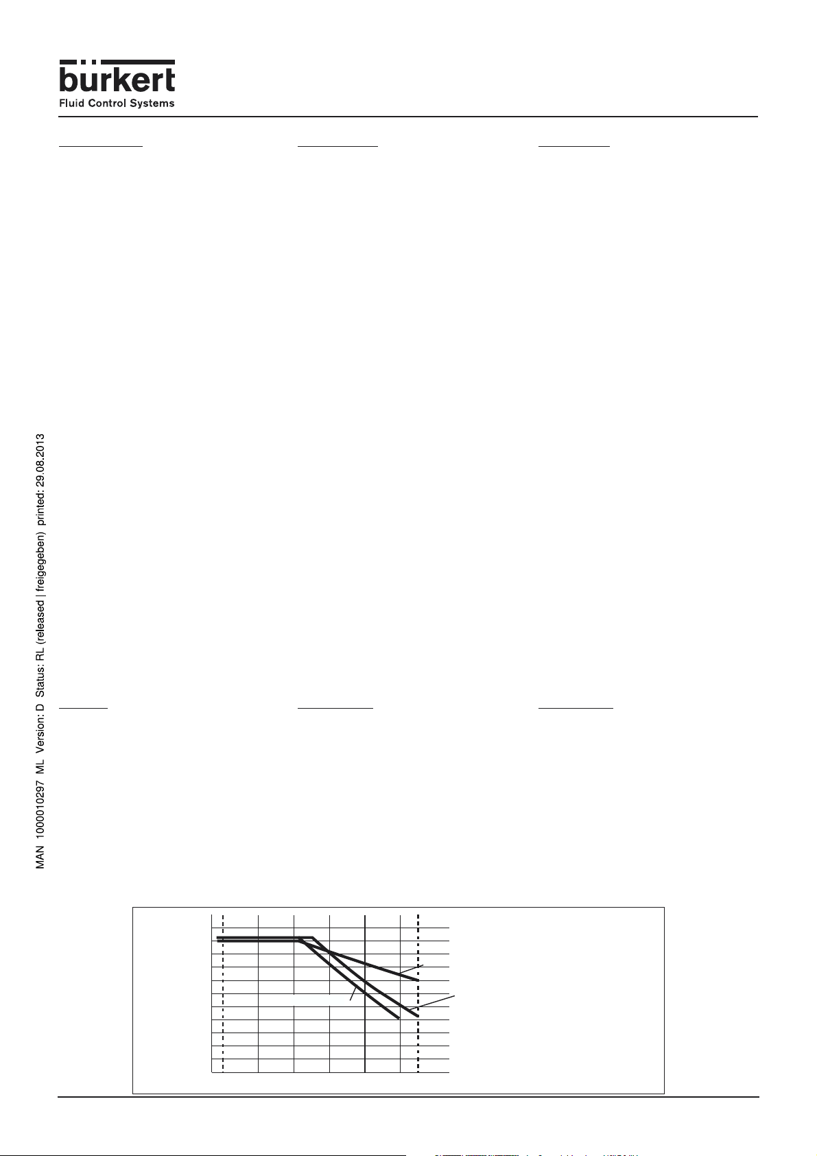
2.2 Druck-Temperatur Diagramm
(für Kunststoff):
Die Druck-Temperatur-Abhängigkeit der verwendeten
Fitting-Werkstoffe ist zu beachten.
Siehe folgendes Diagramm.
Druck
Pressure (bar)
Pression
11
10
9
8
7
6
5
4
3
2
1
0
+10 +30 +50
0
2. Installation
2.1 Installation guidelines
- Use only with pure and water ressembling fluids
(solids content max. 1%, viscosity max.100 cSt ).
- The fluid must be free from air bubbles and
magnetisable particles.
- Upstream and downstream straight pipe lengths
respectively 10xDN in and 3xDN out from sensor.
- Installed in either horizontal or vertical pipes.
- Device not designed for gas flow measurement.
2.2 Pressure temperature Diagram
(for plastic):
Please be aware of the pressure-temperature
dependence according to the respective fitting material.
See diagram below.
Prozessbereich der Fittings S010: 0-55 °C
Application range for fittings S010: 0-55 °C
Plage d’utilisation des raccords S010 : 0-55 °C
PVDF (PN 10)
PVC (PN 10)
+55
PP (PN 10)
Temperatur
Temperature (°C)
Température
2. Installation
2.1 Consignes de montage
- Uniquement pour fluides propres (particules solides
max. 1%, viscosité max.100cSt.).
- Fluides sans bulles d‘air et sans particules
magnétisables.
- Distance amont-aval rectiligne / capteur:
respectivement 10xDN et 3xDN.
- Inclinaison indifférente.
- Inadapté pour les gaz.
2.2 Diagramme température-pression
(pour plastique):
Suivant la nature du matériau du raccord, il faut tenir
compte de la dépendance température-pression.
Cf. diagramme ci-dessous.
Page 2

Mechanischer Durchfluss-Schalter 8010
Mechanical flow switch 8010
Détecteur de débit mécanique 8010
2.3 Auswahl des Schaltpunktes
Der Schaufeltyp (Bereich 1 oder 2) sowie die Nennweite
des Fittings bestimmen den Durchflussbereich, auf
dem der Schaltpunkte eingestellt wird. Die folgende
Tabelle zeigt die Extremwerte desSchaltpunktes für
das ausgewählte Gerät Typ 8010.
2.3 Switching threshold selection
The type of blade (Range1 or 2)and the fitting DN
define the flow range on which the switching
thresholds can be adjusted. The table below shows
the switching end values depending on the selected
model of type 8010.
Bereich Fitting Strömungsgeschwindigkeit Durchfluss / Flow rate / Débit
Range Fitting Fluid velocity/Vitesse du fluide
Plage Raccord (Wasser / Water / Eau) l/min m3/h
DN min. m/s max. min. max. min. max.
15 0.65 Ú 0.90 6.9 9.5 0.41 0.57
15 0.60 Ø 0.80 6.4 8.5 0.38 0.51
20 0.35 Ú 0.55 6.6 10.4 0.40 0.62
20 0.25 Ø 0.45 4.7 8.5 0.28 0.51
1
25 0.40 Ú 0.60 11.8 17.7 0.71 1.06
25 0.30 Ø 0.50 8.8 14.7 0.53 0.88
32 0.65 Ú 0.90 31.4 43.4 1.88 2.61
32 0.55 Ø 0.70 26.5 33.8 1.59 2.03
40 0.75 Ú 1.00 56.5 75.4 3.39 4.52
40 0.60 Ø 0.90 45.2 67.9 2.71 4.07
32 0.18 Ú 0.28 8.5 13.5 0.51 0.81
32 0.15 Ø 0.22 7.0 10.5 0.42 0.63
2
40 0.25 Ú 0.45 18.8 33.9 1.13 2.04
40 0.20 Ø 0.35 15.1 26.4 0.90 1.58
50 0.49 Ú 0.59 58.0 70.0 3.48 4.20
50 0.36 Ø 0.51 42.0 60.0 2.52 3.60
2.4 Einbau
a) Mechanischer Anschluss:
Die Pfeile auf dem S010 INLINE und dem SE10
müssen in die Strömungsrichtung zeigen.
1. Das Fitting (1) in die Rohrleitung einbauen.
2. Das Modul SE10 (2) in das Fitting S010 INLINE
einsetzen und mit der seitlichen Schraube (3) die
Verbindung sichern.
b) Elektrischer Anschluss:
1. Schraube (4) herausdrehen.
2. Das Innenteil (5) herausnehmen.
3. Anschlussbelegung gemäss folgender Abbildung
durchführen; d er Anschluss ist bei stromlos geöffneter
(NO) bzw. geschlossener (NC ) Konfiguration gleich.
4. Beim Zusammenbau kann der Einsatz (5) beliebig in
180° -Schritten eingesetzt werden (der dichtung (6)
nicht vergessen, beim Aufbau Kabelkopf / Modul) .
2.4 Installation
a) Mechanical connection:
The arrows on the S010 INLINE and on the
!!
SE10 must correspond to the flow direction.
1.Install the fitting (1) into the pipe.
2.Fasten the housing SE10 (2) to the fitting S010
INLINE and tighten the whole with the side
screw(3).
b) Electrical connection:
1. Remove the screw (4)
2. Remove internal part (5).
3. Connect according to the pin assignement, the
electrical wiring is the same for NO and NC versions.
4. When re-assembling, the terminal block (5) may be
inserted in 180° steps (don’t forget the gasket
(6) when mounting connector on housing) .
2.3 Sélection seuil de commutation.
Le type de palette (Plage 1 ou 2) ainsi que le DN du
raccord déterminent la plage de débit sur laquelle la
valeur de commutation peut être ajustée. Le tableau
ci-dessous donne les valeurs extrêmes de
commutation suivant la configuration du 8010
sélectionnée.
DN15 DN20 DN25 DN32 DN40
0
DN32 DN40 DN50
0
Flow rate increases
Flow rate decreases
10 20 30 40 50 60 70 80
Flow rate increases
Flow rate decreases
10 20
30 40
2.4 Montage
a) Raccordement mécanique:
Orientez les flèches du S010 INLINE et du
!
SE10 dans le sens de l‘écoulement.
50 60 70 80
1.Installer le raccord (1) sur la conduite.
2.Insérer le boîtier SE10 (2) sur le raccord S010
INLINE et verrouiller l‘ensemble avec la vis
latérale (3).
b) Raccordement électrique:
1. Dévisser la vis (4)
2. Sortez l’insert (5).
3. Raccorder suivant les indications ci-dessous, le
câblage est identique pour les versions NO et NC.
4. Lors du remontage, l’insert (5) peut-être tourné
de 180° (ne pas oublier le joint (6) lors du montage
du connecteur sur le boîtier).
Bereich1
Range1
Plage1
Q(l/min)
Bereich2
Range2
Plage2
Q(l/min)
2
1
3
c) Schutzbeschaltungen :
Induktive Lasten:
Bei Gleichspannung wird zum Kontaktschutz eine
Freilaufdiode parallel zur Last geschaltet, wobei die
Polung so durchgeführt werden muss, dass die
Diode bei der normal anliegender Betriebsspannung
sperrt. Beim Unterbrechen des Stromkreises wird
die in entgegengesetzter Richtung auftretende
Spannungsspitze kurzgeschlossen und somit eine
Lichtbogenbildung zwischen den Schaltzungen
vermieden (Abb.1).
Bei Wechselspannung ist ein Kontaktschutz mittels
Diode nicht möglich. Hier empfiehlt es sich, ein RCGlied zu verwenden, das parallel zum Reedkontakkt
geschaltet wird (Abb.2). Die Dimensionierung eines
solchen RC-Gliedes kann anhand eines Diagramms
erfolgen (Abb.4-Beispiel1).
Leitungsdose nach DIN43650 mit KabelVerschraubung, Leitungsquerschnitt bis max. 1,5 mm
Schutzart IP65.
DIN 43650 cable plug, IP65 rating, with cable gland,
6
5
cable cross section max. 1.5 mm
Connecteur 4 pôles selon DIN43650, IP65, avec
4
presse-étoupe pour fils de 1,5 mm
1
3
c) Wiring precautions:
Inductive Load:
With DC voltage, a recovery diode must be connected
in parallel with the load to protect the contact, so that
the diode is reversed to the current when switching
on the contact. At switching off, the reverse voltage
created at load is short-circuited to avoid electric arcing
at Reed contacts (Fig.1).
With AC voltage, diode protection is not possible. A
RC element must be used, connected in parrallel with
the Reed contact (Fig.2).
The RC element can be chosen using the diagram
below (Fig.4-example1).
2
.
2
max.
1 : Reed Schalter / Reed Contact / Contact Reed
2 : Reed Schalter / Reed Contact / Contact Reed
3 : Nicht belegt / Not assigned / Non utilisé
: Nicht belegt / Not assigned / Non utilisé
2
c) Précautions de câblage:
Charge inductive:
Pour réaliser une protection du contact en tension continue, il faut câbler une diode de roue libre en parrallèle
sur la charge, de façon à ce que la diode soit câblée
en inverse lors de la fermeture du contact. Lors de
l’ouverture du contact, la tension inverse, apparaissant au niveau de la charge, est court circuitée et évite
l’apparition d’un arc électrique au niveau des contacts
du Reed (Fig.1).
En tension alternative, la protection par diode n’est
pas possible. Il faut donc employer un réseau RC
série, branché en parrallèle sur le contact Reed (Fig.2).
Le dimensionnement du réseau RC peut s’effectuer à
l’aide de l’abaque (Fig.4-exemple1).
2
,
Page 3

DN 25DN 25
I
L
H
J
M
K
N
Mechanical flow switch 8010
DN 25
DN 25
DN 25
Détecteur de débit mécanique 8010
Mechanischer Durchfluss-Schalter 8010
Port connection DN Variable dimensions [inch]
(Dimension G2) L L2 H
NPT 9/16" 15 3.35 0.67 1.36
NPT 3/4" 20 3.74 0.72 1.26
NPT 1" 25 4.14 0.71 1.27
NPT 1 1/4" 32 4.73 0.83 1.41
NPT 1 1/2" 40 5.12 0.79 1.56
3. Dimensions
3.1: Acier inox, laiton : Taraudage
H
NPT Anschlussgewinde / NPT-Port connection / Raccordement NPT
G2
L2
DN 25
L
NPT 2" 50 5.91 0.95 1.80
[inch]
Port connection DN Variable dimensions [inch]
(Dimension G2) L L2 H
G 3/4" 15 3.31 0.45 1.36
G 1" 20 3.70 0.53 1.26
G 1 1/4" 25 4.09 0.55 1.27
G 1 1/2" 32 4.69 0.71 1.41
M 55x2 40 5.08 0.75 1.56
M 64x2 50 5.87 0.78 1.80
G2
DN 25
L
H
L2
øD e L H
25 1.33 2.0 4.09 1.27
32 1.67 2.0 4.69 1.41
40 1.90 2.0 5.08 1.56
50 2.37 2.6 5.87 1.80
Port connection DN Variable dimensions [mm]
Weld-end port 15 0.84 1.6 3.31 1.36
connection 20 1.06 1.6 3.70 1.26
[inch]
* DIN 2501, length according to DIN 3202-F1;
* ANSI B16-5-1988, length according to DIN 3202-F1;
* JIS 10K, length according to ANSI B16-10
Normen / Normes / Normes
o D
e
DN 25
L
3. Dimensions
3. Abmessungen
Port connection DN Variable dimensions [mm]
(Dimension G2) L L2 H
Rc 1/2" 15 85 15.0 34.5
G 3/4" 20 95 17.0 32.0
G 1" 25 105 23.5 32.2
Rc 3/4" 20 95 16.3 32.0
G 1 1/4" 32 120 23.5 35.8
G 1 1/2" 40 130 23.5 39.6
G 2" 50 150 27.5 45.7
3.1: Stainless-steel, brass: internal thread
3.1: Edelstahl, Messing : Innengewinde
Rc-Anschlussgewinde / Rc-Port connection / Raccordement Rc
Port connection DN Variable dimensions [mm]
(Dimension G2) L L2 H
G 1/2" 15 85 16.0 34.5
G-Anschlussgewinde / G-Port connection / Raccordement G
Rc 1" 25 105 18.0 32.2
Rc 1 1/4" 32 120 21.0 35.8
Rc 1 1/2" 40 130 19.0 39.6
Rc 2" 50 150 24.0 45.7
Port connection DN Variable dimensions [mm]
(Dimension G2) L L2 H
G 3/4" 15 8 4 11.5 34.5
G 1" 20 94 13.5 32.0
[mm]
3.2: Edelstahl, Messing : Außengewinde 3.2: Stainless-steel, brass: external thread 3.2: Acier inox, laiton : filetage extérieur
H
øD e L H
25 33.7 2.0 104 32.2
32 42.4 2.0 119 35.8
40 48.3 2.0 129 39.6
50 60.3 2.6 149 45.7
Port connection DN Variable dimensions [mm]
Weld-end port 15 21.3 1.6 84 34.5
G 1 1/4" 25 104 1 4 32.2
G 1 1/2" 32 119 1 8 35.8
M 55x2 40 129 1 9 39.6
M 64x2 50 149 2 0 45.7
Port connection DN Variable dimensions [mm]
(Norm) l J (number x ø) K M N L H
DIN [mm] 15 23.5 4 x 14.0 65.0 95.0 45.0 130 34.5
ANSI [inch] 15 (9/16) 0.93 4 x .62 2.38 3.51 1.38 5.12 1.36
JIS [mm] 15 23.5 4 x 15.0 70.0 95.0 51.0 140 34.5
DIN [mm] 20 28.5 4 x 14.0 75.0 105.0 58.0 150 32.0
ANSI [inch] 20 (3/4) 1.12 4 x .62 2.75 3.90 1.69 5.91 1.26
JIS [mm] 20 28.5 4 x 15.0 75.0 100.0 56.0 152 32.0
DIN [mm] 25 28.5 4 x 14.0 85.0 115.0 68.0 160 32.2
ANSI [inch] 25 (1) 1.12 4 x .62 3.13 4.26 2.00 6.30 1.27
JIS [mm] 25 28.5 4 x 19.0 90.0 125.0 67.0 165 32.2
DIN [mm] 32 31.0 4 x 18.0 100.0 140.0 78.0 180 35.8
ANSI [inch] 32 (1 1/4) 1.22 4 x .75 3.50 4.61 2.50 7.09 1.41
JIS [mm] 32 31.0 4 x 19.0 100.0 135.0 76.0 178 35.8
DIN [mm] 40 36.0 4 x 18.0 110.0 150.0 88.0 200 39.6
ANSI [inch] 40 (1 1/2) 1.42 4 x .75 3.88 5.00 2.88 7.88 1.56
JIS [mm] 40 36.0 4 x 19.0 105.0 140.0 81.0 190 39.6
DIN [mm] 50 41.0 4 x 18.0 125.0 165.0 102.0 230 45.7
ANSI [inch] 50 (2) 1.62 4 x .75 4.75 5.99 4.02 9.06 1.80
3.3: Edelstahl mit Flanschen 3.3: Stainless-steel with flanges 3.3: Acier inox, raccord à brides
JIS [mm] 50 41.0 4 x 19.0 120.0 155.0 96.0 216 45.7
3.4: Edelstahl mit Schweißenden nach ISO 4200 3.4: Stainless-steel welding ends according to ISO 4200 3.4: Acier inox, raccord à souder suivant ISO 4200
[mm]
connection 20 26.9 1.6 94 32.0
Page 4

True union ASTM
ISO
PVDF PVDF
LøDH
Variable dimensions [inch]
25 6.30 1.99 1.27
32 7.09 1.99 1.41
40 7.87 2.52 1.56
50 9.06 3.05 1.80
Mechanical flow switch 8010
Détecteur de débit mécanique 8010
Mechanischer Durchfluss-Schalter 8010
DN[mm] / (inch) øD L L1 L3 H
Port connection DN Variable dimensions [inch]
Triclamp port 15 5.12 1.34 1.36
[inch]
connection 20 5.91 1.99 1.26
o D
DN 25
H
o D
L
H
15 / (9/16") 0.79 5.04 3.55 3.78 1.36
[inch] - only for PVC
L3
L2
L1
20 / (3/4") 0.99 5.67 3.94 4.18 1.26
25 / (1") 1.26 6.30 4.33 4.57 1.27
32 / (1 1/4") 1.58 6.62 4.33 4.57 1.41
40 / (1 1/2") 1.97 7.41 4.73 5.00 1.56
50 / (2") 2.48 8.35 5.12 5.36 1.80
True union JIS
Ø D L L1 L3 H
40 48.70 196 120 127 39.6
Port connection DN Variable dimensions [inch]
[inch] - PVC / PP / PVDF
50 60.80 219 130 136 45.7
PVC PP PVC PP
[mm (inch)] øD L L2 H
32 (1 1/4") 1.58 4.33 3.94 1.08 .79 1.41
40 (1 1/2") 1.97 4.72 4.17 1.18 .91 1.56
50 (2") 2.48 5.12 4.33 1.46 1.06 1.80
Solvent joint or 15 (9/16") .79 3.54 3.35 .65 .55 1.36
weld-end 20 (3/4") .99 3.94 3.62 .79 .63 1.26
connection 25 (1") 1.26 4.33 3.74 .91 .71 1.27
Bestelltabelle / Ordering Chart / Tableau de commande
o D
Ausführungen / Versions / Modèles Ident Nr. / Ident-No./ code Ident.
SE10 with Reed Contact: Normally Open (International standard version) 4380 87
SE10 with Reed Contact: Normally Closed (International standard version) 438088
L
44
L2
H
54
3.5: Stainless-steel with Triclamp according to ISO 2852 3.5: Acier inox, Triclamp suivant ISO 2852
LøDH
25 160 50.5 32.2
32 180 50.5 35.8
Port connection DN Variable dimensions [mm]
Triclamp port 15 130 34 34.5
3.5: Edelstahl mit Triclamp nach ISO 2852
[mm]
connection 20 150 50.5 32.0
Port connection DN Variable dimensions [mm ]
True union 15 18.40 135 90 96 34.5
connection with 20 26.45 151 100 106 32.0
solvent/ fusion 25 32.55 167 110 116 32.2
[mm] - only for PVC
spigot 32 38.60 175 110 116 35.8
True union ISO
Variable dimensions [mm]
40 200 64 39.6
50 230 77.5 45.7
DN øD L L1 L3 H
15 20 128 90 96 34.5
20 25 144 100 106 32.0
25 32 160 110 116 32.2
32 40 168 110 116 35.8
40 50 188 120 127 39.6
3.6: PVC/PP/PVDF mit Überwurfmutter; Klebe- oder Schweissmuffen 3.6: PVC/PP/PVDF True union connection; solvent/fusion spigot 3.6: Raccord union en PVC/PP/PVDF; avec manchon à coller / à souder
[mm] - for PVC/PP/PVDF
50 63 212 130 136 45.7
ISO
PVDF PVDF
PVC PP PVC PP
øD L L2 H
Port connection DN Variable dimensions [mm]
Solvent joint or 15 20 90 85 16.5 14 34.5
weld-end 20 25 100 92 20 16 32.0
3.7: PVC/PP/PVDF ; Klebe- oder Schweißende 3.7: PVC/PP/PVDF connection; solvent/fusion spigot 3.7: Raccord en PVC/PP/PVDF; avec embouts à coller / à souder
[mm] - PVC / PP / PVDF
connection 25 32 110 95 23 18 32.2
32 40 110 100 27.5 20 35.8
40 50 120 106 30 23 39.6
50 63 130 110 37 27 45.7
Abmessungen / Dimensions / Dimensions (mm)
75
48.5
32
3.8: Modul SE10 3.8: SE10 Module 3.8: Module SE10
Page 5

Mechanischer Durchfluss-Schalter 8010
Mechanical flow switch 8010
Détecteur de débit mécanique 8010
Kapazitive Lasten und Lampenlasten:
Bei kapazitiven Lasten und insbesondere bei
Lampenlasten können Einschaltströme bis zum 15fachen des Nennwertes auftreten, die u. U. zu Störungen
bis hin zum Verschweißen der Kontakte führen. Aus
diesem Grund sollte beim Schalten von Kapazitäten,
Glühlampen und anderen Verbrauchern über lange
Kabelstrecken dem Reedschalter ein Schutzwiderstand
zur Strombegrenzung in Reihe geschaltet werden
(Abb.3).
Der Reihenwiderstand sollte grundsätzlich so groß wie
möglich sein, wobei die genaue Dimensionierung vom
jeweiligen Schaltkreis bestimmt wird. Eine Richtgröße
kann mit Hilfe des Kontakschutz-Diagramms ermittelt
werden (Abb.4-Beispiel2).
Kontaktschutz-Diagramm (Abb.4):
Beispiel 1(siehe Abb.2): I = 0,1 A
U = 220 V
Legen Sie ein Lineal durch o.g. Punkte. Sie können
nun auf den entsprechenden Achsen die zugehörigen
Werte für den Kondensator C und den Widerstand R
ablesen.
In diesem Beispiel: C = 0,001 µF
R = 340 Ohm
Beispiel 2 (siehe Abb.2):
I = 0,5 A (Max. zulässiger Einschaltstromstoß)
Legen Sie ein Lineal durch o.g. Punkte. Sie können
nun auf den entsprechenden Achsen die zugehörigen
Werte für den Mindest-Widerstand R
In diesem Beispiel: R
U = 200 V
min
= 400 Ohm
min
ablesen.
Abb.1 / Fig.1
+
Reed Schalter
Switch Reed
Interrupteur Reed
-
Abb.2 / Fig.2
Abb.3 / Fig.3
d) Schaltpunkt Stellung:
Der Schaltpunkt wird mittels der Stellschraube (2mm
Imbuss-Schlüssel) eingestellt.
Nach rechts drehen spannt den Mechanismus, der
Durchfluss muss dann grösser sein um zu schalten.
Die Stellschraube Anschläge entsprechen nicht
!
genau den minimalen und maximalen
Schaltpunktgrenzen. Im allgemeinen wird die
Stellschraube um 180° gedreht.
Wenn das Modul SE10 in das Fitting S010 INLINE
!
eingesetzt wird bei laufendem Prozess, muss der
Mechanismus zurückgestellt werden. Die
Stellschraube muss nach links gedreht werden und
zurück zur Arbeitstellung.
Reed Schalter
Switch Reed
Interrupteur Reed
Schutzwiderstand
Protect resistor
Résistance de protection
Reed Schalter
Switch Reed
Interrupteur Reed
Capacitive and lamp type loads:
For capacitive loads and especially lamps,
switching current may reach 15 times the nominal current, and weld the contacts.
In this case a current limiting resistor must be
integrated into the circuit (Fig.3).
The series resistance must be as high as possible, with the accuracy dependant on the circuit used.
An example is given below (Fig.4-example2).
Diagram of switch protection:
Example 1(see Fig.2): I = 0,1 A
Draw a line using the above data. The RC element
values can be read on the corresponding axes.
U = 220 V
In that case: C = 0,001 µF
R = 340 Ohm
Example 2(see Fig.3):
I = 0,5 A (switching current max.)
U = 200 V
Draw a line using the above data. The minimal
value for the resistance R can be read on the
corresponding axis.
In that case: R
= 400 Ohm
min
Abb.4 / Fig.4
Last
Diode
Load
Charge
Last
Load
Charge
Last
Load
Charge
d) Switching threshold setting:
The switching threshold setting is made by rotating
the setting screw (2 mm Allen key). A rotation to the
right strengthens the mechanism, the flow must be
higher to switch the contact.
The setting screw limits don’t show exactly the
!
minimum and maximum switching threshold value. Usually, the adjustment is made on a 180° rotation.
If housing SE10 is installed on the fitting
!
S010 INLINE while the process is running,
reset the mechanism by rotating the setting
screw home to left, and back to previous position.
10
8
6
4
3
2
1
0,1
0,08
0,06
0,04
0,03
0,02
0,01
0,008
0,006
0,004
0,003
0,002
0,001
Kapazität in µF / Capacitance in µF / Capacité en µF
0,0001
Charge capacitive et de type lampe:
Pour des charges capacitives et particulièrement pour
les lampes, peuvent apparaître des courants d’enclenchement atteignant 15 fois le courant nominal, ce qui
peut entraîner la soudure du contact. Dans ce cas, il
faut insérer dans le circuit une résistance de limitation du courant (Fig.3).
La résistance série doit être aussi grande que possible, cependant le dimensionnement précis dépend du
circuit utilisé. Une valeur indicative peut être trouvée
à l’aide de l’abaque (Fig.4-exemple2).
Abaque de protection du contact:
Exemple 1(cf. Fig.2): I = 0,1 A
Tracer un trait passant par les données ci-dessus.
Les valeurs des composants RC pourront alors être
lues sur les axes correspondants.
Exemple 2 (cf. Fig.3):
Tracer un trait passant par les données ci-dessus. La
valeur minimale de la résistance R pourra alors être
lue sur l’axe correspondant.
Nennstrom in A
Rated current in A
Courant nominal en A
10
8
7
6
5
4
3
2
1
Spannung in V
0,9
0,8
Voltage in V
0,7
Tension en V
5
6
8
0,5
10
0,4
20
0,3
0,2
0,1
0,09
0,08
0,07
0,06
0,05
0,04
0,03
0,02
0,01
30
20 A
10 A
5 A
2 A
1 A
0,5 A
max. Einschaltstromstoß
max. inrush current
Courant d'enclenchement maxi.
d) Réglage du seuil de commutation:
Le réglage du seuil de commutation s’effectue par la
vis de réglage (clé six pans de 2). Une rotation vers la
droite durcit le mécanisme, le débit nécessaire à la
commutation sera plus élevé.
!
max. En général, le réglage s’effectue sur un angle de
rotation d’environ 180°.
!
boîtier en tournant la vis de réglage à fond vers la
gauche et revenir en position initiale.
U = 220 V
Pour cet exemple: C = 0,001 µF
R = 340 Ohm
I = 0,5 A (courant d’enclenchement maxi)
U = 200 V
Pour cet exemple: R
Beispiel 1
Example 1
Exemple 1
500
400
300
200
100
50
300 V
200 V
100 V
50 V
25 V
Spannung / Voltage
10 V
Les butées de la vis de réglage ne représentent
pas exactement les seuils de commutation min et
Si le boitier SE10 est installé sur le raccord S010
INLINE en présence de débit, il faut réarmer le
= 400 Ohm
min
Widerstand in Ohm
Resistivity in Ohm
Résistance en Ohm
Beispiel 2
Example 2
Exemple 2
10000
8000
6000
5000
4000
3000
2000
1000
800
600
500
400
300
200
100
80
60
50
40
30
20
10
8
6
5
4
3
2
1
Page 6

Mechanischer Durchfluss-Schalter 8010
Mechanical flow switch 8010
Détecteur de débit mécanique 8010
4. Technische Daten
Nennweiten DN15 bis 50
Schaltungbereich siehe Auswahltabelle
Durchflussgeschwindigkeit 10 m/s max.
Druckklasse Kunststoff-Fitting PN10
Mediumstemperatur 0...55°C max.
Umgebungs- und Lagertemperatur 0°C bis +55 °C
Schutzart IP65 mit festge-
Werkstoffe
Schaufel PVDF
Schaufel achse VA (1.4404)
O-Ringe FPM oder EPDM
Fitting S010 INLINE PVC, PP, PVDF,
Gehäuse PC, Glasfaser
Stellschraube Vernickeltes Messing
Gerätstecker Polyamid
Reed-Schalter Form A
Schaltspannung 150VDC/250VAC max.
Schaltstrom 0.8A max.
Schaltleistung 50W max., 50VA
Arbeitstrom 2,5A
Metall-Fitting PN16
(siehe Diagramm Seite 1)
schraubtem Stecker
VA (1.4404)
MS (CuZn39Pb2)
verstärkt
4. Technical Data
Pipe diameters DN15 to 50 (1/2“ to2“)
Switching range see selection table
Flow velocity max. 10 m/s
Pressure class Plastic fitting PN10
Fluid temperature 0°...55°C max.
Ambient and storage
temperature 0°C to +55 °C
Protection class IP65 with screwed on
Material
Blade PVDF
Blade axis Stainl. Steel (316L)
O-rings FPM or EPDM
Fitting S010 INLINE PVC, PP, PVDF,
Housing PC, glass fiber
Setting screw Plated brass
Cable plug Polyamid
Reed Contact Form A
Switching voltage 150VDC/250VAC max.
Switching Current 0.8A max.
Switching power 50W max., 50 VA
Carrying current 2,5A
Metal fitting PN16
(see diagram p.1)
cable plug
Stainl. Steel (316L)
Brass (CuZn39Pb2)
reinforced
4. Caractéristiques techniques
Diamètres conduites DN 15 à 50
Plage de commutation cf. tableau de sélection
Vitesse max. du fluide 10 m/s
Classe de pression Raccord plastique PN10
Température du fluide 0°C...55°C max.
Température ambiante
et de stockage 0°C à +55 °C
Protection IP65 avec le
Matériaux
Palette PVDF
Axes palette Acier inox (316L)
Joint torique FPM ou EPDM
Raccord S010 INLINE PVC, PP, PVDF,
Boîtier PC, renforcé fibre
Vis de réglage Laiton nickelé
Connecteur Polyamide
Ampoule Reed Forme A
Tension commutable 150VDC/250VAC max.
Courant commutable 0.8A max.
Puissance commutable 50W max. ,50 VA
Courant de travail 2,5A
Raccord métal PN16
(cf diagramme p.1)
connecteur vissé
Acier inox (316L)
Laiton (CuZn39Pb2)
de verre
5. Fitting-Bestelltabelle / Ordering Chart for Fittings / Tableau de commande des raccords
Bestell-Nr. / Order code / Référence de commande
Edelstahl / Stainless-Steel / Acier inoxydable
G-port connection (internal thread) 438199 438200 438201 438202 438205 438203 438206 438207
NPT-port connection (internal thread) 438208 438209 438210 438211 438214 438212 438215 438216
JIS (ISO 7)-port connection (internal thread) 438217 438218 438219 438220 438223 438221 438224 438225
G-port connection (external thread) 438226 438227 438228 438229 438232 438230 438233 438234
Weld-end port connection 438235 438236 438237 438238 438241 438239 438242 438243
Flange-port connection (DIN 2501 438253 438254 438255 438256 438259 438257 438260 438261
Flange-port connection (ANSI B16-5-1988) 438262 438263 438264 438265 438268 438266 438269 438270
Flange-port connection (JIS 10K)) 438271 438272 438273 438274 438277 438275 438278 438279
Triclamp-port connection (ISO 2852) 438244 438245 438246 438247 438250 438248 438251 438252
Schaufel Bereich / Blade range / Plage Palette 1 2 1 2
DN 15 DN 20 DN 25 DN 32 DN40 DN 50
Messing / Brass / Laiton
G-port connection (internal thread) 438163 438164 438165 438166 438169 438167 438170 438171
NPT-port connection (internal thread) 438172 438173 438174 438175 438178 438176 438179 438180
JIS (ISO 7)-port connection (internal thread) 438181 438182 438183 438184 438187 438185 438188 438189
G-port connection (external thread) 438190 438191 438192 438193 438196 438194 438197 438198
PVC
True union connection with solvent spigot (International standard version) 438091 438092 438093 438094 438097 438095 438098 438099
True union connection with solvent spigot (North America standard version) 438109 438110 438111 438112 438115 438113 438116 438117
True union connection (JIS standard) 438118 438119 438120 438121 438124 438122 438125 438126
Solvent joint connection 438100 438101 438102 438103 438106 438104 438107 438108
PP
True union connection with solvent spigot 438127 438128 438129 438130 438133 438131 438134 438135
Weld-end connection 438136 438137 438138 438139 438142 438140 438143 438144
PVDF
True union connection with solvent spigot 438145 438146 438147 438148 438151 438149 438152 438153
Weld-end connection 438154 438155 438156 438157 438160 438158 438161 438162
6. Ersatzteile-Bestelltabelle / Ordering Chart for spare parts / Tableau de commande des pièces détachées
Dichtungsatz FPM für Metall-Fittings / FPM gasket set for metal fittings / Jeu de joints FPM pour raccords en métal, DN15 - DN50 426340
Dichtungsatz EPDM für Metall-Fittings / EPDM gasket set for metal fittings / Jeu de joints EPDM pour raccords en métal, DN15 - DN50 426341
DIN43650-Stecker mit Kabelverschraubung / Cable plug DIN43650 with cable gland / Connecteur DIN43650 avec presse-étoupe (Typ / type 2508) 438811
DIN43650-Stecker mit NPT1/2"-Reduktion / Cable plug DIN43650 with NPT1/2"-reduction / Connecteur DIN43650 avec réduction NPT1/2" (Typ / type 2509) 162673
Dichtungsatz FPM für Kunststoff-Fittings / FPM gasket set for plastic fittings / Jeu de joints FPM pour raccords en plastique, DN15 431555
Dichtungsatz FPM für Kunststoff-Fittings / FPM gasket set for plastic fittings / Jeu de joints FPM pour raccords en plastique, DN20 431556
Dichtungsatz FPM für Kunststoff-Fittings / FPM gasket set for plastic fittings / Jeu de joints FPM pour raccords en plastique, DN25 431557
Dichtungsatz FPM für Kunststoff-Fittings / FPM gasket set for plastic fittings / Jeu de joints FPM pour raccords en plastique, DN32 431558
Dichtungsatz FPM für Kunststoff-Fittings / FPM gasket set for plastic fittings / Jeu de joints FPM pour raccords en plastique, DN40 431559
Dichtungsatz FPM für Kunststoff-Fittings / FPM gasket set for plastic fittings / Jeu de joints FPM pour raccords en plastique, DN50 431560
© Bürkert 1999
Technische Änderung vorbehalten
Subject to change without notice
Sous réserve de modifications techniques
00439693-Ind_B
Order code
 Loading...