

Page 1

Page 2

Page 3

CONTENTS
Page
1. General description 4
1.1 Applications 4
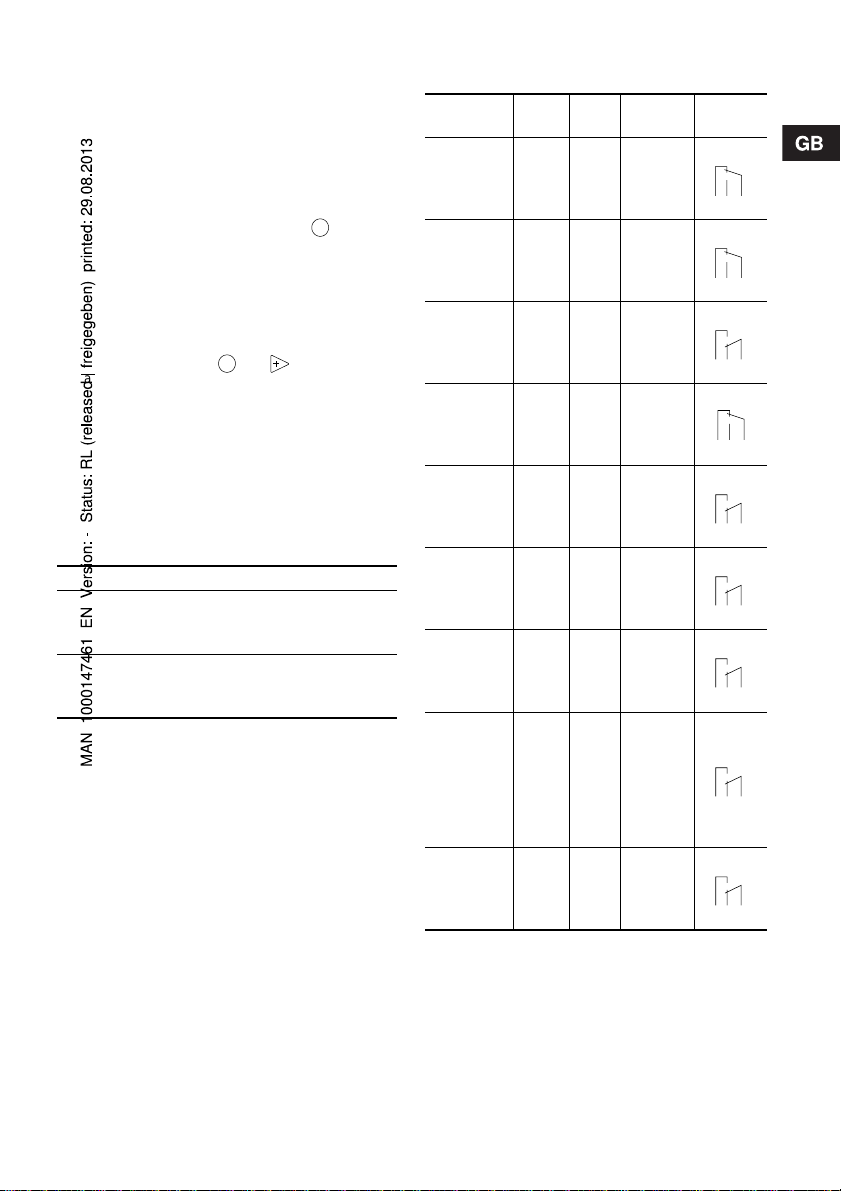
1.2 Type key 5
2. Technical data 6
2.1 Mechanical data 6
2.2 Electrical data 6
2.3 Input/output data 6
2.4 Dimensions 7
3. Installation 7
3.1 Safety instructions 7
3.2 Installation environment 7
3.3 Installation of pump 7
3.4 Installation example 8
3.5 Electrical connection 8
3.6 Connection overview 9
4. Functions 10
4.1 Control panel 10
4.2 Start/stop of pump 11
4.3 Priming/venting of pump 11
4.4 Level control 11
4.5 Indicator lights and alarm output 11
4.6 Fieldbus communication 12
4.7 Menu 13
4.8 Operating modes 14
4.9 Manual 14
4.10 Pulse 14
4.11 Analog 14
4.12 Timer 16
4.13 Batch 17
4.14 Anti-cavitation 17
4.15 Capacity limitation 18
4.16 Counters 18
4.17 Resetting 19
4.18 Return 19
4.19 Language 19
4.20 Input setup 20
4.21 Measuring units 21
4.22 Dosing monitoring 22
4.23 Control panel lock 23
5. Start-up 24
6. Calibration 25
6.1 Direct calibration 26
6.2 Indirect calibration 27
6.3 Check calibration 28
7. Maintenance 28
8. Service 28
9. Fault finding chart 29
10. Disposal 29
1. General description
The Buerkert 7800 dosing pump is a self-priming diaphragm pump.
The pump consists of:
•a cabinet incorporating the drive unit and elec-
tronics,
•a dosing head with back plate, diaphragm,
valves, connections and vent valve,
•a contr ol panel incorporating display and buttons .
The control panel can be fitted either to the end or
to the side of the cabinet.
Being equipped with a stepper motor, this dosing
pump is unique in its field. The stepper motor offers
the possibility of varying the capacity by changing
the duration of the dosing stroke.
Furthermore, the motor is controlled in such a way
that the dosing gets as even and constant as possible, irrespective of the capacity range in which the
pump is operating.
This is carried out as follows:
The speed of the suction stroke is kept constant and
the stroke relatively short, irrespective of the capacity . Contrary to conv entional pumps, which generate
the dosing stroke as a short pulse, the duration of
the dosing stroke will be as long as possible. Thus,
an even dosing without peak values is ensured. As
the pump is always dosing at full stroke length, it ensures the same high accuracy and suction capability,
irrespective of the capacity, which is infinitely variable in the ratio of 1:1000.
The pump features an LCD display and a userfriendly control panel which gives access to the
pump functions.
1.1 Applications
The 7800 dosing pump is designed for handling
chemicals within the following ranges of applications,
among others:
• Drinking water treatment.
• Wastewater treatment.
• Swimming pool water treatment.
• Boiler water treatment.
• Cooling water treatment.
• Process water treatment.
• Washing systems.
Before beginning installation procedures,
these installation and operating instructions should be studied carefully. The installation and operation should also be in
accordance with local regulations and accepted codes of good practice.
4
Page 4

2. Technical data
2.1 Mechanical data
Maximum capacity without anti-cavitation *
Maximum capacity with anti-cavitation *
1
[l/h] 2.5 7.5 12 18.5 48
1
[l/h] 1.8 5.6 9 14.5 37
Maximum pressure [bar] 18 10 6 6.2 2.6
Maximum stroke rate per minute [stroke/min.] 180 180 180 151 151
Maximum suction lift during operation [m] 6
Maximum suction lift when priming with wet valves [m] 1.8 3 3 3 3
Maximum viscosity with spring-loaded valves *
Maximum viscosity without spring-loaded valves *
[mPas]
2
[mPas] 500 500 500 500 100
Diaphragm diameter [mm] 28 38 42.5 55 77
Liquid temperature [°C] 0 to 50
Ambient temperature [°C] 0 to 45
Accuracy of repeatability ±1%
Sound pressure level [dB(A)] <70
*1 Irrespective of counter pressure
2
Maximum suction lift 1 metre
*
2.2 Electrical data
Supply voltage [VAC] 1 x 100-240
Maximum current consumption [A]
Maximum power consumption P
at 100 V 0.30 0.36
at 230 V 0.16 0.26
[W] 18 22
1
Frequency [Hz] 50-60
Enclosure class IP 65
Insulation class B
Supply cable 1.5 m H05RN-F with plug
2.3 Input/output data
The pump offers various input and output possibilities, depending on control variant.
Signal input
Voltage in level sensor input [VDC] 5
Voltage in pulse input [VDC] 5
Minimum pulse-repetition period [ms] 3.3
Impedance in analog 4-20 mA input [Ω] 250
Maximum loop resistance in pulse signal circuit [Ω] 350
Maximum loop resistance in level signal circuit [Ω] 350
Signal output
Maximum load of alarm relay output, at ohmic load [A] 2
Maximum voltage, alarm relay output [V] 250
7800-2 7800-8 7800-12 7800-19 7800-48
2
200 200 200 200 100
7800- 2, 8, 12 7800-19, 48
6
Page 5

2.4 Dimensions
See dimensions at the end of these instructions.
All dimensions are in mm.
3. Installation
3.1 Safety instructions
• The liquid is under pressure and may be hazardous.
• When working with chemicals, local safety rules
and regulations must be observed (e.g. wear protective clothes).
• Before starting work on the dosing pump and system, disconnect the electricity supply to the pump,
ensuring that it cannot be accidentally switched
on. Before reconnecting the electricity supply,
make sure that the dosing hose is positioned in
such a way that any chemical left in the dosing
head is not ejected, thereby exposing persons to
danger.
• If the vent valve in the dosing head is used, it must
be connected to a hose which is led back to the
tank.
• When changing a chemical, make sure that the
materials of the dosing pump and system are resistant to the new chemical. If there is any risk of
chemical reaction between the two types of chemicals, clean the pump and system thoroughly before adding the new chemical.
Proceed as follows:
Place the suction tube in water and press the
button until residual chemical has been removed.
Note: When the buttons and are pressed
simultaneously, the pump can be set to run for a
specific number of seconds at maximum capacity.
The remaining number of seconds will appear in
the display. The maximum value is 300 seconds.
100%
3.2 Installation environment
• Exposure to direct sunlight should be avoided.
This applies especially to pumps with plastic dosing heads, as this material can be damaged by
sunlight.
• If the pump is installed outside, an enclosure or
similar protection is required to protect the pump
against rain and similar weathers.
100%
3.3 Installation of pump
• See also the installation example in section 3.4.
• Note: The dosing head may contain water from
the factory test. If a liquid which must not come
into contact with water is to be dosed, it is recommended to let the pump run with another liquid to
remove the water from the dosing head before installation.
• Note: Tighten the bolts in the dosing head after
2 to 5 operating hours (torque 5 Nm).
• Always install the pump on the supporting foot
with vertical suction and discharge ports.
• Always use suitable tools for the mounting of plastic parts. Never apply unnecessary force.
• Make sure that the dosing pump and system are
designed in such a way that neither system equipment nor buildings are damaged in case of leakage from the pump or rupture of hoses/pipes. The
installation of leakage hoses and collecting tanks
is recommended.
• Make sure that the drain hole in the dosing head
points downwards, see fig. 1.
Note: It is important that the drain pipe/hole is not
inserted direct into the tank contents, as gasses
may penetrate into the pump.
Fig. 1
Drain hole
TM01 8420 5099
7
Page 6

3.4 Installation example
The drawing in fig. 2 shows an installation example.
Fig. 2
The 7800 pump can be installed in many different ways. The sketch below shows a n example with sidefitted control panel. The tank is a Buerkert chemical tank with a Buerkert level control unit.
3.5 Electrical connection
• The electr ical connection of the pump should be
carried out by qual ified perso ns in accordance
with local regulations.
• For electr ical data of the pump, see section 2.2.
• Do not lay signal cables, if any, together with
power cables.
8
TM01 8421 0 204
Page 7

3.6 Connection overview
Fig. 3
Alarm relay (control variant “AR” only)
“NO” black
“NC” blue
“Com” brown
5
4
4
5
1
3
2
Control cable,
see table below
1
3
2
4
1
3
Level cable,
see table below
2
3
1
4
Empty tank
Low level
Control input:
Number / colour 1 / brown 2 / white 3 / blue 4 / black 5 / grey Description
Function
Manual 2 2
Pulse 1 1
Pulse + external on/off 1 1 + 2 2
Analog – + mA signal
Analog + external on/off 2 2 – + mA signal
Timer + external on/off 2 2
Batch 1 1
1 = Contact for pulse signal
2 = Contact for external on/off
Level input:
Number / colour 1 / brown 2 / white 3 / blue 4 / black
Low level Low level
Function
Low level Empty tank Low level + empty tank
Empty tank Empty tank
Dosing monitoring Dosing monitoring
TM01 8422 0603
9
Page 8

4. Functions
4.1 Control panel
Fig. 4
Navigation/
settings,
see section 4.7
Maximum capacity
(priming),
see section 4.3
LCD display,
see section 4.7
ml/h
Navigation/
settings,
see section 4.7
Green
indicator light,
see section 4.5
Red
indicator light,
see section 4.5
Connection
alarm relay/bus.
Control variants
“AR”, “AP” and “AG”,
see sections 4.5 and
4.6
100%
M12 connection
pulse/analog input,
see section 4.4
level control,
see section 4.4
Menu,
see section 4.7
On/off button,
see section 4.7
Mains connectionM12 connection
TM01 8423 0100
10
Page 9
4.2 Start/stop of pump
The pump can be started/stopped in two different
ways:
• Locally on the pump control panel.
• By means of an external on/off switch connected
to the pulse input. See connection overview in
section 3.6.
4.3 Priming/venting of pump
The pump control panel incorporates a button.
Press this button if the maximum pump capacity is
required over a short period, e.g. during start-up.
When the button is released, the pump automatically
returns to the previous operating mode.
During priming/venting, it is recommended to let the
pump run without a counter pressure or to loosen the
vent valve by giving it a 1/8 to 1/4 turn.
Note: When the buttons and are pressed si-
multaneously, the pump can be set to run for a specific number of seconds at maximum capacity. The
remaining number of seconds will appear in the display. The maximum value is 300 seconds.
100%
100%
4.4 Level control
The pump can be fitted with a level control unit for
monitoring of the chemical level in the tank.
The pump can react to two level signals. The pump
will react differently, depending on the influence on
the individual level sensors.
Level sensors Pump reaction
Upper sensor
activated
(closed contact)
Lower sensor
activated
(closed contact)
• Red indicator light is on.
• Pump running.
• Alarm relay activated.*
• Red indicator light is on.
• Pump stopped.
• Alarm relay activated.*
* Control variant “AR” only.
See section 3.6 for connection of the level control
unit and alarm output.
4.5 Indicator lights and alarm output
The green and red indicator lights on the pump are
used for operating and fault indication.
In control variant “AR”, the pump can activate an external alarm signal by means of a built-in alarm relay.
The alarm signal is activated by means of an internal
potential-free contact.
The functions of the indicator lights and the built-in
alarm relay appear from the table below:
Condition
Pump
running
Set to stop
Green
LED
On Off
Flash-
ing
Red
LED
Off
Display
Normal
indication
Normal
indication
Alarm
output
132
NC NO C
132
NC NO C
Pump fault Off On EEPROM
23
1
NC NO C
Supply
failure
Off Off Off
132
NC NO C
Pump running, low
chemical
2
level
Empty
2
tank
Analog
signal
On On
Off On
Off On
< 2 mA
The dosed
quantity is
too small
according
to the signal from the
dosing
monitor
Overheating
1
Control variant AR only.
2
Requires connection to level sensors.
3
Requires activation of the dosing monitoring
function and connection to a dosing monitor.
On On
3
Off On
Normal
indication
Normal
indication
Normal
indication
Normal
indication
MAX.
TEMP.
23
1
NC NO C
23
1
NC NO C
23
1
NC NO C
23
1
NC NO C
23
1
NC NO C
1
11
Page 10

4.6 Fieldbus communication
The pump can be configured for fieldbus applications.
The following bus types are available:
Control variant Bus type
AP Profibus
AG GENIbus
Separate instructions are supplied with each bus
type.
12
Page 11

4.7 Menu
The pump features a user-friendly menu which is activated by pressing the button. During start-up, all
texts will appear in English language. To select language, see section 4.19.
Fig. 5
See section 4.9 See section 4.23
All menu items are described in the following sections. When appears at a menu item, it means
that this item is activated. By selecting “RETURN”
anywhere in the menu structure, you will return to the
operating display without changes.
See section 4.10 See section 4.17
See section 4.11 See section 4.18
See section 4.12 See section 4.19
See section 4.13 See section 4.15
See section 4.14 See section 4.20
See section 6 See section 4.21
See section 4.16
13
Page 12

4.8 Operating modes
Note: The displayed l and ml values are only reliable
if the pump has been calibrated to the actual installation, see section 6.
The pump can run in five different operating modes:
•Manual
•Pulse
•Analog
•Timer (internal batch control)
•Batch (external batch control)
See description in the following sections.
4.9 Manual
The pump is dosing as constantly and evenly as possible, without any external signals.
Set the quantity to be dosed in l/h or ml/h. The pump
automatically changes over between the measuring
units.
Setting range:
DME 2: 2.5 ml/h - 2.5 (1.8*) l/h
DME 8: 7.5 ml/h - 7.5 (5.6*) l/h
DME 12: 12 ml/h - 12 (9*) l/h
DME 19: 18.5 ml/h - 18.5 (14.5*) l/h
DME 48: 48 ml/h - 48 (37*) l/h
* The figures in brackets indicate the maximum ca-
pacity when the anti-cavitation function is activated.
Fig. 6
Set value
4.10 Pulse
The pump is dosing according to an external pulse
signal, i.e. a water meter with pulse output or a controller.
Set the quantity to be dosed per pulse in ml/pulse.
The pump adjusts its capacity according to two factors:
• Frequency of external pulses.
• The set quantity per pulse.
Setting range:
DME 2: 0.000018 ml/pulse - 5 ml/pulse
DME 8: 0.000069 ml/pulse - 15 ml/pulse
DME 12: 0.000111 ml/pulse - 24 ml/pulse
DME 19: 0.000204 ml/pulse - 37 ml/pulse
DME 48: 0.00530 ml/pulse - 96 ml/pulse
Fig. 7
Set quantity in
ml/pulse
Actual capacity
in ml/h or l/h
If the set quantity per pulse multiplied by the pulse
frequency exceeds the pump capacity, the pump will
run at maximum capacity. Excess pulses will be ignored and the “actual capacity” display will flash.
4.11 Analog
The pump is dosing according to an external analog
signal. The dosed quantity is proportional to the input
value in mA.
4-20 (default): 4 mA = 0%.
20-4: 4 mA = 100%.
0-20: 0 mA = 0%.
20-0: 0 mA = 100%.
See fig. 8.
The capacity limitation will influence the capacity.
100% corresponds to the maximum capacity of the
pump or the set maximum capacity, see section
4.15.
Fig. 8
100
80
60
40
20
20 mA = 100%.
20 mA = 0%.
20 mA = 100%.
20 mA = 0%.
[%]
0-20 mA
4-20 mA
0
0 4 8 12 16 20
[mA]
TM02 4498 1102
14
Page 13

Fig. 9
Value
according to
analog signal
If 4-20 mA or 20-4 mA is selected and the signal falls
below 2 mA, the pump will indicate a fault. This situation occurs if the connection is interrupted, for instance if the wire is damaged.
Change the analog mode as illustrated in fig. 10:
Fig. 10
Use the buttons
for navigation
15
Page 14

4.12 Timer
The pump is dosing the set quantity in batches at the
maximum capacity or the set maximum capacity, see
section 4.15.
The time until the first dosing “NX” and the following
sequences “IN” can be set in minutes, hours and
days. The maximum time limit is 9 days, 23 hours
and 59 minutes (9:23:59). The lowest acceptable
value is 1 minute.
if the pump is stopped by means of the on/off button,
empty tank or stop signal, see fig. 11.
During operation, “NX” will always count down from
“IN” to zero. In this way, the remaining time until the
next batch can always be read.
“IN” must be higher than the time required to perform
one batch. If “IN” is lower, the next batch will be ignored.
In case of supply failure, the set quantity to be
dosed, the “IN” time and the remaining “NX” time are
stored. When the supply is reconnected, the pump
will start up with the “NX” time at the time of the supply failure. In this way, the timer cycle will continue,
but it has been delayed by the duration of the supply
failure.
Fig. 11
NX
Setting range:
7800-2: 0.23 ml/batch - 5 l/batch
7800-8: 0.69 ml/batch - 15 l/batch
7800-12: 1.11 ml/batch - 24 l/batch
7800-19: 2.04 ml/batch - 37 l/batch
7800-48: 5.3 ml/batch - 96 l/batch
Only values corresponding to complete dosing
strokes (according to the calibration factor) can be
selected.
Example: If the calibration factor is 23.3 (= 0.233 ml/
stroke), the minimum settable value in timer or batch
mode will be 0.233 ml -> the next will be 0.466 ml ->
the next will be 0.699 ml, etc.
These steps will continue up to a value corresponding to 100 dosing strokes. Above this value, the setting range has standard steps as in other operating
modes.
If the calibration factor is changed after setting of
timer or batch mode, the pump will automatically recalculate a new amount of dosing strokes per batch
and change the display value to the nearest possible
value compared to the first one set.
The internal timer continues even
Quantity per batch
IN
Fig. 12
TM01 8942 0900
Set quantity
per batch
Set IN value
in minutes
Set IN value
in hours
Set IN value
in days
Set NX value
in minutes
Set NX value
in hours
Set NX value
in days
16
Page 15

4.13 Batch
The pump is dosing the set quantity in batches at the
maximum capacity or the set maximum capacity, see
section 4.15.
The quantity is dosed every time the pump receives
an external pulse.
If the pump receives new pulses before the previous
batch is performed, these pulses will be ignored.
Fig. 13
Quantity per batch
Pulse Pulse
The setting range is the same as for Timer, see section 4.12.
Fig. 15
Fig. 14
Set value
per batch
4.14 Anti-cavitation
The pump features an anti-cavitation function. When
this function is selected, the pump extends and
smooths its suction stroke, resulting in softer priming.
The anti-cavitation function is used:
• when pumping liquids of high viscosity,
TM01 8947 0900
• in the case of a long suction tube and
• in the case of a high suction lift.
The maximum pump capacity is reduced when this
function is selected. See section 2.1 Mechanical
data.
Operating display
17
Page 16

4.15 Capacity limitation
This function offers the possibility of reducing the
maximum pump capacity (MAX CAP). It influences
the functions in which the pump is normally operating
at maximum capacity.
Under normal operating conditions, the pump cannot
operate at a capacity which is higher than the one
stated in the display. This does not apply to the maximum capacity button , see section 4.3.
Fig. 16
100%
Fig. 17
Total dosed
quantity
Set maximum
capacity
Operating display
4.16 Counters
The pump can display “non-resettable” counters for:
•“QUANTITY”
Accumulated value of dosed quantity in litres or
US gallons.
•“STROKES”
Accumulated number of dosing strokes.
•“HOURS”
Accumulated number of operating hours.
•“POWER ON”
Accumulated number of times the electricity supply has been switched on.
Total number
of strokes
Total number
of operating
hours
Total number
of starts
18
Operating display
Page 17

4.17 Resetting
When “DEFAULT” is activated, the pump will return
to the factory settings.
Fig. 18
Note: The calibration is also set back to the default
setting. This means that a new calibration is required
when the “DEFAULT” function has been used.
Operating display Operating display
4.18 Return
Fig. 19
The “RETURN” function makes it possible to return
from any level in the menu to the operating display
without changes after the menu functions have been
used.
without changes
4.19 Language
The display text can be displayed in one of the following languages:
• English
•German
•French
•Italian
• Spanish
• Portuguese
•Dutch
• Swedish
• Finnish
• Danish
•Czech
•Slovak
•Polish
• Russian
19
Page 18

Fig. 20
Operating display Operating display
4.20 Input setup
Fig. 21 shows all possible settings.
The level and stop inputs can be changed from NO
(normally open) to NC (normally closed) function. If
changed, the inputs must be short-circuited in normal operation.
Fig. 21
Use the buttons
for navigation
Operating display
without changes
For the analog input, one of the following signal
types can be selected:
• 4-20 mA (default),
• 20-4 mA,
• 0-20 mA,
• 20-0 mA.
See also section 4.11 Analog.
Change the level input to an input for dosing monitor-
ing as illustrated in fig. 21.
20
Page 19

4.21 Measuring units
It is possible to select metric units (litre/millilitre) or
US units (gallons/millilitre).
Metric measuring units:
• In manual and analog modes, set the quantity to
be dosed in litres per hour (l/h) or millilitres per
hour (ml/h).
• In pulse mode, set the quantity to be dosed in
ml/pulse. The actual capacity is indicated in litres
per hour (l/h) or millilitres per hour (ml/h).
• For calibration, set the quantity to be dosed in
ml per 100 strokes.
• In timer and batch modes, set the quantity to be
dosed in litres (l) or millilitres (ml).
• Under the “QUANTITY” menu item in the
“COUNTERS” menu, the dosed quantity is indicated in litres.
Fig. 22
3 x
US measuring units:
• In manual and analog modes, set the quantity to
be dosed in gallons per hour (gph).
• In pulse mode, set the quantity to be dosed in
ml/pulse. The actual capacity is indicated in
gallons per hour (gph).
• For calibration, set the quantity to be dosed in
ml per 100 strokes.
• In timer and batch modes, set the quantity to be
dosed in gallons (gal).
• Under the “QUANTITY” menu item in the
“COUNTERS” menu, the dosed quantity is indicated in US gallons (gal).
Operating display Operating display
21
Page 20

4.22 Dosing monitoring
A dosing monitor is available as an accessory. Separate instructions are supplied with the monitor.
Fig. 23
Dosing stroke measured
Monitor mounted on the suction side of the pump
The dosing monitor is designed to monitor the dosing
of liquids which may cause gas accumulation in the
dosing head, thus stopping the dosing process even
if the pump is still operating.
For every measured dosing stroke, the dosing monitor gives a pulse signal to the level input so that the
pump can compare performed dosing strokes (from
internal stroke sensor) with externally measured
physical strokes (from the dosing monitor). If an external dosing stroke is not measured together with
the internal dosing stroke, this is considered a fault
that may have been provoked by empty tank or gas
in the dosing head.
TM02 2029 3201
22
Page 21

4.23 Control panel lock
It is possible to lock the buttons on the control panel
to prevent malfunction of the pump. The locking
function can be set to “ON” or “OFF”. The default
setting is “OFF”.
A PIN code must be entered to change from “OFF” to
“ON”. When “ON” is selected for the first time,
“_ _ _ _” will appear in the display. If a code has already been entered, it will appear when an attempt
to change to “ON” is made. This code can either be
re-entered or changed.
If no code has been entered, a code must be set in
the same way as the “NX” and “IN” values described
in section 4.12.
If a code has already been entered, active digits are
flashing.
If attempts are made to operate the pump in locked
condition, “LOCKED” will appear in the display for
2 seconds, followed by “_ _ _ _”. A code must be entered. If the entering of a code has not been started
within 10 seconds, the operating display without
changes will appear.
Fig. 24
If a wrong code is entered, “LOCKED” will appear in
the display for 2 seconds, followed by “_ _ _ _”. A
new code must be entered. If the entering of a code
has not been started within 10 seconds, the operating display without changes will appear. This display
will also appear if the entering of the correct code exceeds 2 minutes.
If the locking function has been activated but the
control panel is unlocked, the control panel will be
locked automatically if it is not operated for 2 minutes.
The locking function can also be reactivated by selecting “ON” in the “LOCK” menu. The previously entered code will then appear and must be re-entered
by pressing the button four times. The code can
also be changed.
The control panel can be unlocked either by means
of the selected code or the factory code 2583.
The following buttons and inputs are still active when
the panel is locked:
• Priming ( -button).
100%
• On/off button.
• All external inputs.
Operating display
Activating the locking function and locking the
control panel:
1. Select “LOCK” in the menu.
2. Select “ON” by means of the buttons and
and confirm with .
3. Enter or re-enter a code by means of the buttons
, and .
The locking function has now been activated and the
control panel is locked.
Unlocking the control panel (without deactivating
the locking function):
1. Press once. “LOCKED” appears in the display
for 2 seconds, followed by “_ _ _ _”.
2. Enter the code by means of the buttons ,
and *.
The control panel has now been unlocked and will
automatically be locked again if the control panel is
not operated for 2 minutes.
Operating display
Deactivating the locking function:
1. Unlock the control panel as described above.
2. Select “LOCK” in the menu.
3. Select “OFF” by means of the buttons and
and confirm with .
The locking function has now been deactivated and
the control panel is unlocked.
* The panel can always be unlocked with code 2583.
23
Page 22

5. Start-up
1
2
100%
Step Action
Connect the hoses/pipes:
• Connect the suction and dosing tubes/pipes to the pump.
• Connect a tube to the vent valve, if required, and lead the hose to the
tank.
Switch on the electricity supply:
• The display is on.
• The green indicator light is flashing (the pump has stopped).
• Select language, if required, see section 4.19.
3
Select the operating mode (see section 4.8):
• Manual.
•Pulse.
• Analog.
•Timer.
•Batch.
4
Connect the cables:
• Connect the control/level cables, if any, to the pump, see section 3.6.
5
Start the pump:
• Start the pump by pressing the on/off button.
100%
6
100%
• The green indicator light is permanently on.
Priming/venting:
• Press the button on the pump control panel and let the pump run
without a counter pressure. Loosen the vent valve by giving it a 1/8 to
1/4 turn, if required.
When the buttons and are pressed simultaneously during priming, the pump can be set to run for a specific number of seconds at
maximum capacity.
100%
100%
7
Calibration:
• When the pump has been primed and is running at the right counter
pressure, calibrate the pump, see section 6.
If the pump is not operating satisfactorily, see section 9. Fault finding chart.
24
Page 23

6. Calibration
It is important that the pump is calibrated after installation to ensure that the correct value (ml/h or l/h)
appears in the display.
The calibration can be carried out in three different
ways:
• Direct calibration (recommended).
The dosed quantity of 100 strokes is measured directly. See section 6.1.
• Indirect calibration.
A calibration factor selected from a table is used
for the specific installation. This method can be
used if it is not possible to carry out a direct calibration. Indirect calibration will never be as accurate as direct calibration. See section 6.2.
• Check calibration. See section 6.3.
25
Page 24

6.1 Direct calibration
Before calibration, make sure:
• that the pump is installed with foot valve, injection
valve, etc. in the existing system.
• that the pump is running at the counter pressure it
is supposed to operate at (adjust the counter pressure valve, if required).
• that the pump is operating with the correct suction
lift.
To carry out a direct calibration, proceed as follows:
Action Pump display
1. Prime the dosing head and the suction tubing.
2. Stop the pump. The green LED is flashing.
3. Fill a graduated glass with dosing liquid, Q
7800-2: approx. 40 ml 7800-19: approx. 500 ml
7800-8: approx. 150 ml 7800-48: approx. 1000 ml
.
1
7800-12: approx. 250 ml
4. Read and note the quantity Q
.
1
5. Place the suction tubing in the graduated glass.
Q
1
6. Go to the calibration menu, see section 4.7.
7. Press the button twice.
8. The pump is performing 100 dosing strokes.
9. The factory-calibration value appears in the display.
10.Remove the suction tubing from the graduated
glass and read Q
11.Set the display value to Q
.
2
Q
d
Q
2
= Q1 – Q2.
d
12.Confirm with the button.
13.The pump is now calibrated and returns to the operating display.
26
Set value
to Q
d
Operating display
Page 25

6.2 Indirect calibration
7800-8
7800-12
7800-19
7800-48
A value from the following table is to be added to the
default factory calibration value in the display. To reset the pump to the factory calibration value, activate
the “DEFAULT” function, see section 4.17.
To use the values, the following must be fulfilled:
• The viscosity and density of the liquid to be dosed
must not differ considerably from water at 20°C.
• A Grundfos installation kit or corresponding foot
valve, injection valve and hose diameter must be
used.
• The length of the dosing hose must not exceed
6 metres.
• The suction lift must lie between 0.1 and 1.5 metres.
Pump type
7800-2 1.4 1.1 0.8 0.5 0.2 -0.2 -0.6 -1.2 -1.8 -2.4 -3.0 -3.6
Adding the value:
Fig. 25
Values to be added to the calibration value at various counter pressures [bar]
0-1 1-2 2-3 3-4 4-5 5-6 6-8 8-10 10-12 12-14 14-16 16-18
3.52.72.01.20.4-0.4-1.6-3.1----
2.11.30.4-0.4-1.3-2.1-3.4-----
18.312.26.10-6.1-12.2-21.4-----
24.38.3-8.3---------
Set value
to table value
+ display valu e
Operating display
Operating display
without changes
27
Page 26

6.3 Check calibration
In check calibration, the calibration value is calculated by reading the consumption of chemical in a
specific period and comparing this with the number
of dosing strokes performed in the same period.
This calibration method is very accurate and especially suitable for check calibration after long periods
of operation or if direct calibration is impossible. The
calibration can for instance be carried out when the
chemical tank is replaced or filled.
To carry out a check calibration, proceed as follows:
1. Stop the pump by pressing the button.
2. Read the counter and note the number of dosing
strokes, see section 4.16.
3. Read and note the quantity in the chemical tank.
4. Start the pump by pressing the button and let
it run for at least 1 hour. The longer the pump is
operating, the more accurate the calibration will
be.
5. Stop the pump by pressing the button.
6. Read the counter and note the number of dosing
strokes, see section 4.16.
7. Read and note the quantity in the chemical tank.
8. Calculate the dosed quantity in ml and the
number of dosing strokes performed during the
operating period.
9. Calculate the calibration value as follows:
(dosed quantity in ml/dosing strokes) x 100.
10.Set the calculated value in the calibration menu
like for indirect calibration, see section 6.2.
7. Maintenance
The pump is maintenance-free. However, it is recommended to keep the pump clean.
The dosing pump is produced according to the highest quality standards and has long life. The pump incorporates wear parts such as diaphragm, valve seat
and valve balls.
To ensure long life and to reduce the risk of disturbance of operation, visual checks should be carried
out regularly.
It is possible to order dosing heads, valves and diaphragms in materials which are suitable for the specific liquid to be pumped. See the product numbers
at the end of these instructions.
8. Service
Before returning the pump to Buerkert for service,
the safety declaration at the end of these instructions
must be filled in by authorized personnel and attached to the pump in a visible position.
Note: If a pump has been used for a liquid which is
injurious to health or toxic, the pump will be classified as contaminated.
If Buerkert is requested to service the pump, it must
be ensured that the pump is free from substances
that can be injurious to health or toxic. If the pump
has been used for such substances, the pump must
be cleaned before it is returned.
If proper cleaning is not possible, all relevant information about the chemical must be provided.
If the above is not fulfilled, Buerkert can refuse to
accept the pump for service. Possible costs of returning the pump are paid by the customer.
The safety declaration can be found at the end of these
instructions (only in English).
Note: The replacement of the supply cable must be
carried out by an authorised Buerkert service work-
shop.
28
Page 27

9. Fault finding chart
Fault Cause Remedy
The dosing has
stopped or the output
is too low.
Pump dosing too little
or too much.
Pump dosing irregularly.
Leakage from drain
hole.
Frequent diaphragm
failures.
Valves leaking or blocked. Check and clean valves.
Valves incorrectly installed. Remove and fit valves. Check that the arrow
Suction valve or suction pipe/hose
leaking or blocked.
Suction lift too high. Install the pump in a lower position.
Viscosity too high. Select the anti-cavitation function, see sec-
Pump out of calibration. Calibrate the pump, see section 6.
Pump out of calibration. Calibrate the pump, see section 6.
Valves leaking or blocked. Check and clean the valves.
Diaphragm defective. Install a new diaphragm.
Diaphragm not fastened properly. Install a new diaphragm and ensure that the
Counter-pressure too high (measured at the pump discharge port).
Sediment in dosing head. Clean/flush the dosing head.
on the valve casing is pointing in the liquid
flow direction. Check that all O-rings have
been fitted correctly.
Clean and seal the suction pipe/hose.
Install a priming tank.
tion 4.14.
Install a pipe/hose with larger cross-section.
Fit spring-loaded valves.
diaphragm is fastened properly.
Check the system. Check the injection valve,
if required. Reduce the dosing stroke by fitting
a pulsation dampener.
10. Disposal
Disposal of this product or parts of it must be carried
out according to the following guidelines:
1. Use the local public or private waste collection
service.
2. In case such waste collection service does not
exist or cannot handle the materials used in the
product, please deliver the product or any hazardous materials from it to your nearest Buerkert
company or service workshop.
Subject to alterations.
29
Page 28

15
sectional drawing of the dosing head (7800-19 / -48)
14
13
2
18
4
5
3
6
7
8
10
9
11
12
TM01 9976 3500
30
Page 29

assembly / disassembly of dosing head and valves
31
Page 30

dimensions:
130
110
ml/h
D
160
100%
B
C
98
7800-2 7800-8 7800-12 7800-19 7800-48
A = [mm] 137 192
B = [mm] 239 294
C = [mm] 36 15
D = [mm] 168 188
50
A
TM01 9232 0900
32
Page 31

Page 32

Please copy, fill in and sign this sheet and attach it to the pump returned for service
We hereby declare that this product:
Product type:____________________________
Product number:_________________________
is free from hazardous chemicals, biological and radioactive substances
_________________ _________________
Date and signature Company stamp
60
 Loading...