

Page 1
Type 6712
A
P
Whisper Valve
Operating Instructions
Bedienungsanleitung
Manuel d‘utilisation
en / de / fr
CIRCUIT FUNCTION /
WIRKUNGSWEISE / FONCTION
A
2/2-way valve, normally closed.
2/2-Wege-Ventil, stromlos geschlossen.
Vanne à 2/2 voies, normalement fermée.
2/2 way solenoid valve with medium
isolation
2/2-Wege-Magnetventil mit
Medientrennung
Electrovanne 2/2 voies avec séparation
des fluides
Address / Adresse
Germany / Deutschland / Allemagne
Bürkert Fluid Control Systems
Sales Center
Christian-Bürkert-Str. 13–17
D-74653 Ingelfingen
Tel. + 49 (0) 7940 - 10 91 111
Fax + 49 (0) 7940 - 10 91 448
E-mail: info@burkert.com
International
www.burkert.com
Manuals and data sheets on the Internet: www.burkert.com
Bedienungsanleitungen und Datenblätter im Internet: www.buerkert.de
Instructions de service et fiches techniques sur Internet : www.burkert.fr
© Bürker t Werke GmbH & Co. KG, 2014 - 2019
Operating Instructions 1902/03_EU-ml_00810426 / Original DE
SYMBOLS
▶ designates instructions for risk prevention.
→ designates a procedure which you must carry out.
Warning of serious or fatal injuries:
DANGER
In case of imminent danger.
WARNING
In case of potential danger.
Warning of minor or moderately severe injuries:
CAUTION
DARSTELLUNGSMITTEL
▶ markiert eine Anweisung zur Gefahrenvermeidung.
→ markiert einen Arbeitsschritt, den Sie ausführen müssen.
Warnung vor schweren oder tödlichen Verletzungen:
GEFAHR
Bei unmittelbarer Gefahr.
WARNUNG
Bei möglicher Gefahr.
Warnung vor leichten oder mittelschweren Verletzungen:
VORSICHT
SYMBOLES
▶ identifie une consigne pour éviter un danger.
→ identifie une opération que vous devez effectuer.
Mise en garde contre les blessures graves ou mortelles :
DANGER
En cas de danger imminent.
AVERTISSEMENT
En cas de danger possible.
Mise en garde contre les blessures légères ou moyennement
graves :
ATTENTION
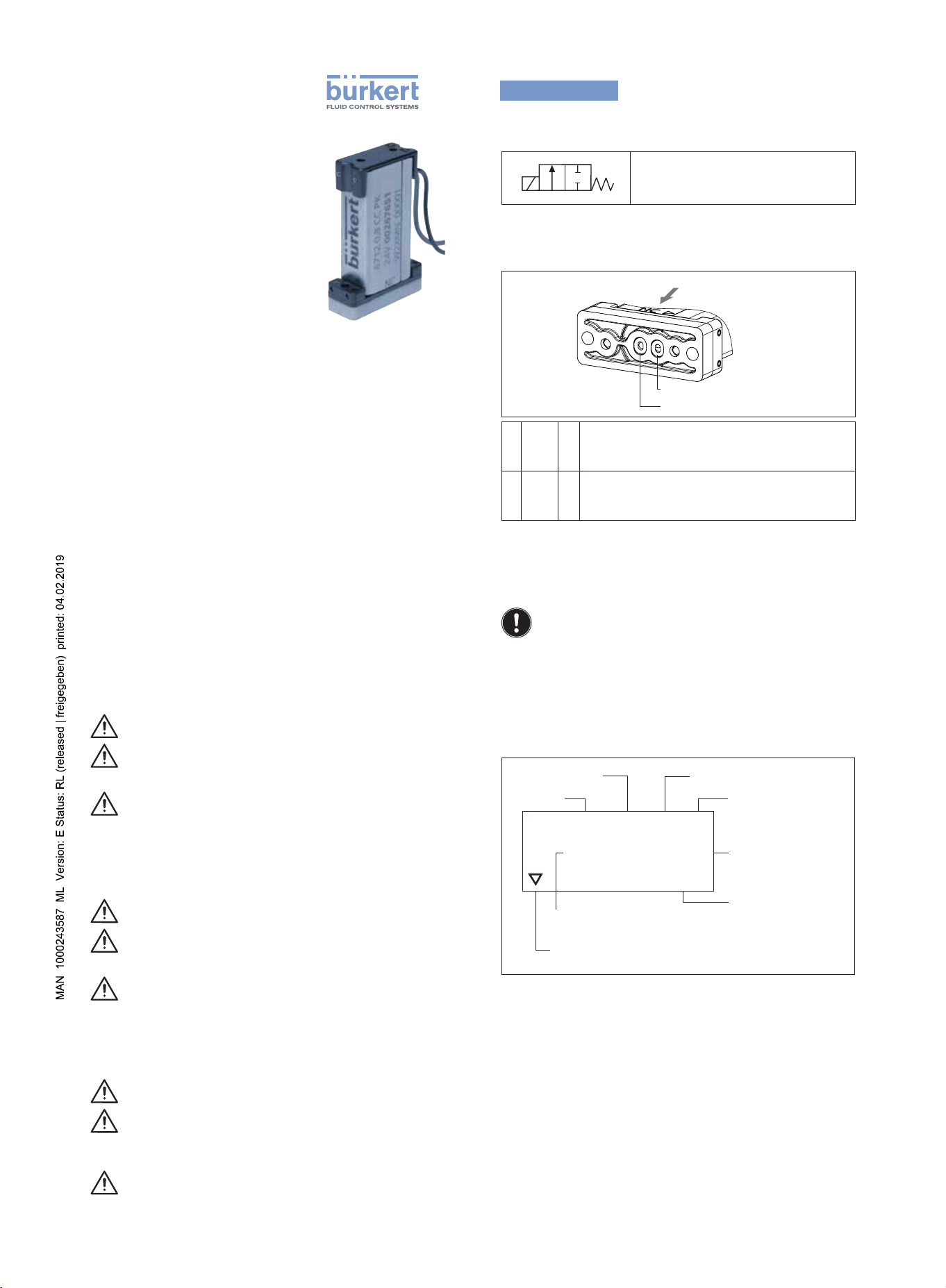
Classification of fluid connections
Zuordnung der fluidischen Anschlüsse
Affectation des raccordements fluidiques
NC
2
1 (normally closed)
Normally closed, pressure connection.
1 NC P
2 OUT A
Stromlos geschlossen, Druckanschluss.
Normalement fermée, raccord de pression.
Joint connection, working connection.
Gemeinsamer Anschluss, Arbeitsanschluss.
Raccord commun, raccord de travail.
TYPE LABEL / TYPSCHILD
PLAQUE SIGNALÉTIQUE
Observe the voltage specified on the type label.
Die auf dem Typschild angegebenen Daten für Spannung
beachten.
Observer les données indiquées sur la la plaque signalétique
pour la tension.
Description of the type label
Beschreibung des Typschilds
Description de la plaque signalétique
Orifice / Nennweite
Diamètre nominal
Type / Typ
6712 0,8 CC PK
NC
24V 00267651
W2XMG 00001
Voltage / Spannung / Tension
Identification pressure connection
Kennzeichnung Druckanschluss
Identification raccord de pression
Body material / Gehäusewerkstoff / Matériau du corps
PK = PEEK, PS = PPS
Seal material / Dichtwerkstoff / Matériau d‘étanchéit
AA = EPDM, FF = FKM, CC= FFKM
Orifice / Nennweite / Diamètre nominal
0,8 = 0,8 mm / 3 bar
0,4 = 0,4 mm / 5 bar
Seal material / Dichtwerkstoff
Matériau d‘étanchéit
Body material
Gehäusewerkstoff
Matériau du corps
Order number
Bestellnummer
No. de commande
Serial number (optional)
Seriennummer (optional)
No. de serie (optionnel)
Page 2
english
Type 6712
1 OPERATING INSTRUCTIONS
The operating instructions contain important information.
▶ Read the instructions carefully and follow the safety instructions in
particular.
▶ Keep the instructions in a location where they are available to every
user.
▶ The liability and warranty for Type 6712 are void if the operating
instructions are not followed.
2 INTENDED USE
The solenoid valve Type 6712 is designed for analytical, medical and
laboratory applications. It is predominantly used to dose and fill liquids
and gases.
▶ Do not use Type 6712 outside without taking suitable protective
measures.
▶ Do not use rectified AC voltage as the power supply without smoothing.
▶ Operate only when in perfect condition and pay attention to correct
storage, transportation, installation and operation.
3 BASIC SAFETY INSTRUCTIONS
WARNING
Danger – high pressure.
▶ Before loosening lines or valves, turn off the pressure and vent the
lines.
Risk of burns/risk of fire if used continuously through hot device
surface.
▶ Keep Type 6712 away from highly flammable substances and
media and do not touch with bare hands.
▶ Do not obstruct the heat release required for operation.
Leaking medium when the diaphragm is worn.
▶ Regularly check for leaking medium.
▶ If the media is hazardous, protect the environment from danger
To prevent injury, ensure the following:
▶ Secure equipment/device from unintentional actuation.
▶ Do not use in potentially explosive area.
▶ Do not make any internal or external changes.
▶ Only trained technicians may perform installation and maintenance
work.
▶ After an interruption in the power supply, ensure that the process is
restarted in a controlled manner.
▶ Observe the general regulations of technology.
5 INSTALLATION / DISASSEMBLY
5.1 Fluid Installation
WARNING
Risk of injury from high pressure in the equipment.
▶ Before loosening lines or valves, turn off the pressure and vent the
lines.
Installation position: any position, preferably with actuator above.
→ Clean pipelines and flange connections.
→ Install dirt filter in the direction of flow in front of the valve (mesh
size 5 μm).
WARNING!
Risk of medium escaping if seal is seated incorrectly.
▶ Make sure that the supplied seal fits properly.
▶ Use only connection plate of adequate quality and with a flat
surface.
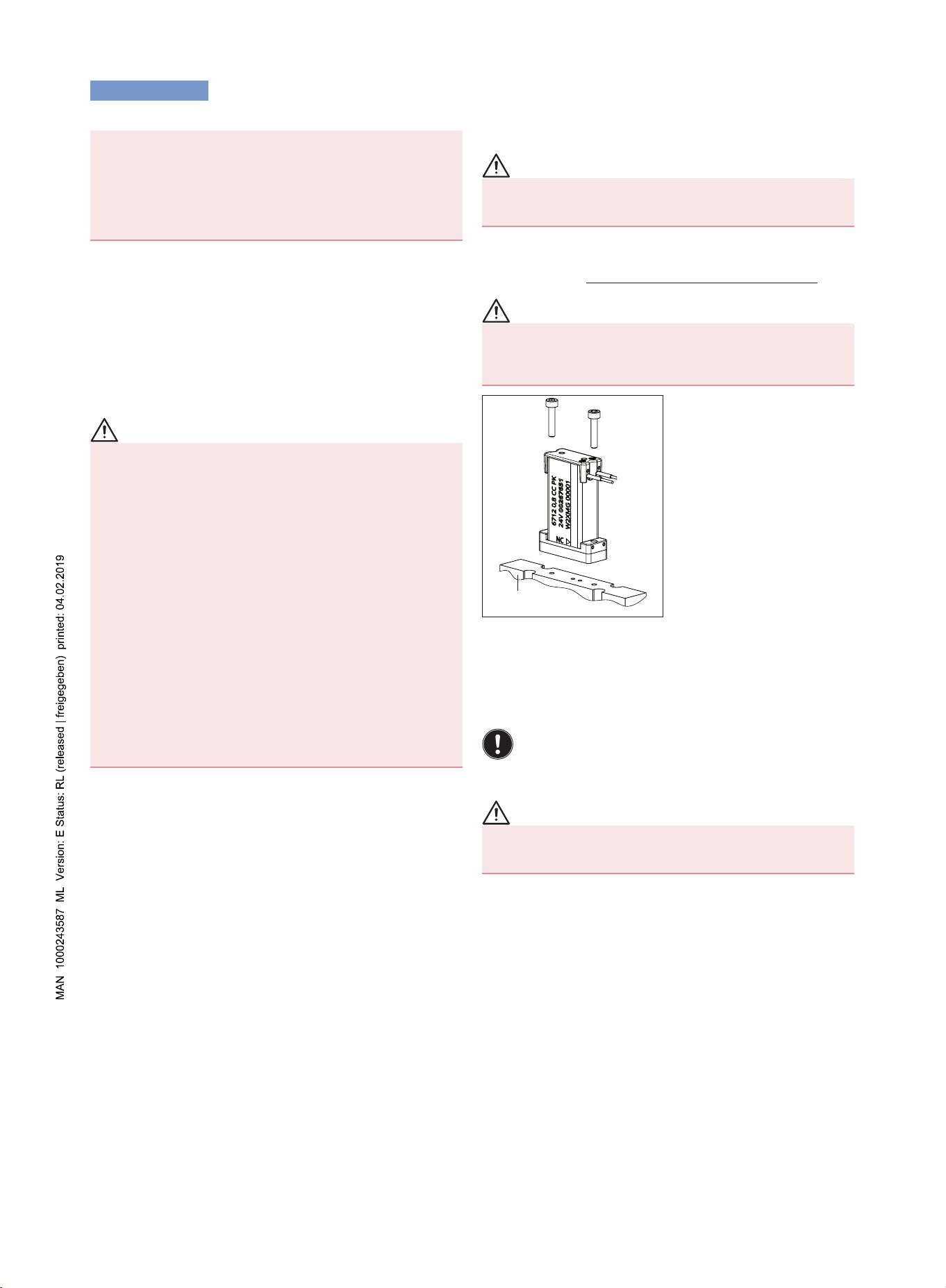
→ Drill holes according to drilling
pattern (dimensions see data
sheet).
→ Correctly assign fluid
connection configuration 1
and 2 on valve and
connection plate.
→ Attach valve with screws.
Recommended tightening
torque when using metric
screws 0.11...0.15 Nm
(different value for PT screws).
→ Check installation for leaks.
Manifold
Fig. 1: Assembly
5.2 Electrical Installation
Electrical power supply: DC, Tolerance ± 10 %
(including residual ripple)
Maximum residual voltage: 1 % of the nominal voltage
Power consumption: 0,9 W
Continuous switching behavior – the opening of the valves follows
the power supply voltage. A power reduction is not possible. If the
polarity is not correct, the valve will not function (see data sheet).
4 TECHNICAL DATA
4.1 Operating Conditions
Permitted temperatures for diaphragm material FKM:
environment: +15 ... +55 °C
medium: +15 ... +55 °C
Extended
temperature ranges: depending on the materials (see data sheet).
Media: aggressive, neutral, gaseous and liquid media
which do not attack housing and seal materials
(see Chemical Resistance Chart at
www.burkert.com). Check that resistance is
adequate in individual cases.
Degree of protection: IP40
Protection class: III acc. to IEC 61140 or
NEC Class II Power Supply
4.2 Conformity
Type 6712 conforms with the EC Directives according to the EC
Declaration of Conformity.
4.3 Standards
The applied standards, which verify conformity with the EC Directives,
can be found on the EC-Type Examination Certificate and / or the EC
Declaration of Conformity.
4.4 Electrical Data see type label.
5.3 Disassembly
WARNING
Risk of injury from hazardous media.
▶ Before loosening lines or valves, flush out hazardous media,
depressurize and drain the lines.
6 MAINTENANCE
→ Regularly check for leaking medium.
7 MALFUNCTIONS
If malfunctions occur, check
• that the fluid connections have been correctly assigned according
to the operating principles,
• whether the operating pressure is within the permitted range,
• the power supply and valve control
• the electric connections have the correct polarity.
8 TRANSPORTATION, STORAGE, DISPOSAL
• Transport and store Type 6712 in shock-resistant packaging to
protect against moisture and dirt.
• Permitted storage temperature: -10 ... +65 °C.
• Permitted transportation temperature: –40 ... +70 °C.
• Dispose of the device and packaging according to the applicable
disposal and environmental protection regulations.
Page 3

deutsch
Typ 6712
1 DIE BEDIENUNGSANLEITUNG
Die Bedienungsanleitung enthält wichtige Informationen.
▶ Die Anleitung sorgfältig lesen und besonders die Hinweise zur
Sicherheit beachten.
▶ Die Anleitung so aufbewahren, dass sie jedem Benutzer zur Verfü-
gung steht.
▶ Die Haftung und Gewährleistung für Typ 6712 entfällt, wenn die
Anweisungen der Bedienungsanleitung nicht beachtet werden.
2 BESTIMMUNGSGEMÄSSER GEBRAUCH
Das Magnetventil Typ 6712 ist für den Einsatz in der Analysen-, Medizinund Labortechnik konzipiert. Es ist vorzugsweise zum Dosieren und
Abfüllen von Flüssigkeiten und Gasen einsetzbar.
▶ Typ 6712 nicht ohne passende Schutzvorkehrung im Außenbereich
einsetzen.
▶ Als Spannungsversorgung keine gleichgerichtete Wechselspan-
nung ohne Glättung verwenden.
▶ Nur in einwandfreiem Zustand betreiben und auf sachgerechte
Lagerung, Transport, Installation und Bedienung achten.
3 GRUNDLEGENDE SICHERHEITSHINWEISE
WARNUNG
Gefahr durch hohen Druck.
▶ Vor dem Lösen von Leitungen oder Ventilen den Druck abschalten
und Leitungen entleeren.
Verbrennungsgefahr/Brandgefahr bei Dauerbetrieb durch heiße
Geräteoberfläche.
▶ Typ 6712 von leicht brennbaren Stoffen und Medien fernhalten und
nicht mit bloßen Händen berühren.
▶ Die für den Betrieb notwendige Wärmeabfuhr nicht behindern.
Austritt von Medium bei Verschleiß der Membran.
▶ Regelmäßig auf austretendes Medium prüfen.
▶ Bei gefährlichen Medien, die Umgebung vor Gefahren sichern.
Zum Schutz vor Verletzungen beachten:
▶ Anlage/Gerät vor unbeabsichtigter Betätigung sichern.
▶ Nicht in explosionsgefährdeten Bereichen einsetzen.
▶ Keine inneren oder äußeren Veränderungen vornehmen.
▶ Nur geschultes Fachpersonal darf Installations- und Instandhal-
tungsarbeiten ausführen.
▶ Nach Unterbrechung der elektrischen Versorgung für einen kont-
rollierten Wiederanlauf des Prozesses sorgen.
▶ Die allgemeinen Regeln der Technik einhalten.
4 TECHNISCHE DATEN
4.1 Betriebsbedingungen
Zulässige Temperaturen für Membranwerkstoff FKM:
Umgebung: +15 ... +55 °C
Medium: +15 ... +55 °C
Erweiterte
Temperaturbereiche: von Materialien abhängig (siehe Datenblatt).
Medien: aggressive, neutrale, gasförmige und flüssige
Medien, die Gehäuse und Dichtwerkstoffe nicht
angreifen (Beständigkeitstabelle unter
www.buerkert.de). Die ausreichende Bestän-
digkeit im Einzelfall prüfen.
Schutzart: IP40
Schutzklasse: III nach IEC 61140 oder
NEC Class II Power Supply
4.2 Konformität
Der Typ 6712 ist konform zu den EG-Richtlinien entsprechend der
EG-Konformitätserklärung.
4.3 Normen
Die angewandten Normen, mit denen die Konformität mit den EGRichtlinien nachgewiesen wird, sind in der EG-Baumusterprüfbescheinigung und/oder der EG-Konformitätserklärung nachzulesen.
4.4 Elektrische Daten siehe Typschild.
5 INSTALLATION / DEMONTAGE
5.1 Fluidische Installation
WARNUNG
Verletzungsgefahr durch hohen Druck in der Anlage.
▶ Vor dem Lösen von Leitungen oder Ventilen den Druck abschalten
und Leitungen entleeren.
Einbaulage: beliebig, vorzugsweise Antrieb oben.
→ Rohrleitungen und Flanschanschlüsse säubern.
→ Schmutzfilter in Strömungsrichtung vor dem Ventil einbauen
(Maschenweite 5 μm).
WARNUNG
Gefahr durch Mediumsaustritt bei unkorrekt sitzender Dichtung.
▶ Auf den richtigen Sitz der mitgelieferten Dichtungen achten.
▶ Nur Anschlussplatte von ausreichender Güte und mit planer Ober-
fläche verwenden.
→ Bohrungen gemäß Bohrbild
anbringen (Maße siehe
Datenblatt).
→ Fluidische Anschluss-
belegung 1 und 2 an Ventil
und Anschlussplatte richtig
zuordnen.
→ Ventil mit Schrauben
befestigen. Empfohlenes
Anziehdrehmoment bei Verwendung metrischer Schrauben
0,11...0,15 Nm (Wert bei PTSchrauben abweichend).
→ Installation auf Dichtheit prüfen.
Anschlussplatte
Bild 1: Montage des Magnetventils
5.2 Elektrische Installation
Spannungsversorgung: DC, Toleranz ± 10 % (inkl. Restwelligkeit)
Maximale Restspannung: 1 % der Nennspannung
Leistungsaufnahme: 0,9 W
Stetiges Schaltverhalten – die Öffnung des Ventils folgt der Versorgungsspannung. Eine Leistungsabsenkung ist nicht möglich.
Richtige Polarität ist Voraussetzung für die Funktion des Ventils
(siehe Datenblatt).
5.3 Demontage
WARNUNG
Verletzungsgefahr durch gefährliche Medien.
▶ Vor dem Lösen von Leitungen oder Ventilen gefährliche Medien
ausspülen, die Leitungen druckfrei schalten und entleeren.
6 WARTUNG
→ Regelmäßig auf austretendes Medium prüfen.
7 STÖRUNGEN
Überprüfen Sie bei Störungen
• die richtige Belegung der fluidischen Anschlüsse entsprechend der
Wirkungsweisen,
• ob sich der Betriebsdruck im zulässigen Bereich befindet,
• die Spannungsversorgung und Ventilansteuerung,
• die richtige Polung der elektrischen Anschlüsse.
8 TRANSPORT, LAGERUNG, ENTSORGUNG
• Typ 6712 vor Nässe und Schmutz geschützt in einer stoßfesten
Verpackung transportieren und lagern.
• Zulässige Lagertemperatur: -10…+65 °C.
• Zulässige Transporttemperatur: -40 … +70 °C.
• Bei der Entsorgung von Gerät und Verpackung die geltenden Entsorgungsvorschriften und Umweltbestimmungen einhalten.
Page 4

français
Type 6712
1 LE MANUEL D’UTILISATION
Le manuel d‘utilisation contiennent des informations importantes.
▶ Lire attentivement le manuel et tenir particulièrement compte des
consignes de sécurité.
▶ Conserver le manuel d’utilisation afin qu’il soie accessible à tous les
utilisateurs.
▶ La responsabilité et la garantie légale concernant le type 6712 sont
exclues en cas de non-respect des instructions de service.
2 UTILISATION CONFORME
L'électrovanne de type 6712 est conçue pour une utilisation en technique
d'analyse, de médecine et de laboratoire. Elle est utilisable de préférence
pour le dosage et le remplissage de fluides et de gaz.
▶ Ne pas utiliser le type 6712 à l'extérieur sans mesures de protec-
tion adaptées.
▶ Ne pas utiliser de tension alternative redressée sans lissage comme
alimentation en tension.
▶ Utiliser uniquement en parfait état et veiller au stockage, au trans-
port, à l'installation et à l'utilisation conformes.
3 CONSIGNES DE SÉCURITÉ
FONDAMENTALES
AVERTISSEMENT
Danger dû à la haute pression.
▶ Avant de desserrer les conduites et les vannes, couper la pression
et purger l'air des conduites.
Risque de brûlures/d'incendie en fonctionnement continu dû à
des surfaces d'appareils brûlantes.
▶ Tenir le type 6712 à l'écart des substances et des fluides facile-
ment inflammables et ne pas le toucher à mains nues.
▶ Ne pas gêner l'évacuation de la chaleur nécessaire au fonctionnement.
Sortie de fluide en cas d’usure de la membrane.
▶ Vérifier régulièrement qu’aucun fluide ne s’échappe.
▶ Dans le cas de fluides dangereux, protéger l’environnement des
dangers.
Pour prévenir les blessures, veuillez tenir compte de ce qui suit :
▶ Empêcher tout actionnement involontaire de l'installation/de l'appareil.
▶ Ne pas utiliser dans une zone exposée à un risque d’explosion.
▶ Ne pas effectuer de modifications à l’intérieur ou à l’extérieur.
▶ Seul du personnel qualifié peut effectuer l'installation et la
maintenance.
▶ Garantir un redémarrage contrôlé du processus après la coupure
de l'alimentation électrique.
▶ Respecter les règles générales de la technique.
4 CARACTÉRISTIQUES TECHNIQUES
4.1 Conditions d'exploitation
Températures autorisées pour le matériau de membrane FKM :
Environnement : +15 ... +55 °C
Fluide : +15 ... +55 °C
Plages de température
étendues : en fonction des matériaux (voir fiche technique).
Fluides : fluides liquides et fluides neutres gazeux
agressifs n’attaquant pas le matériau du corps
et du joint. (voir le tableau de résistance
chimique Bürkert sous www.buerkert.fr).
Contrôler si la résistance est suffisante au cas
par cas.
Degré de protection : IP40
Classe de protection : III selon IEC 61140 ou
NEC Class II Power Supply
4.2 Conformité
Le type 6712 est conforme aux directives CE comme stipulé dans la
déclaration de conformité CE.
4.3 Normes
Les normes appliquées justifiant la conformité aux directives CE
peuvent être consultées dans le certificat d’essai de modèle type CE
et / ou la déclaration de Conformité CE.
4.4 Caractéristiques électriques voir plaque signalétique.
5 INSTALLATION / DÉMONTAGE
5.1 Installation fluidique
AVERTISSEMENT
Risque de blessures dû à la présence de haute pression dans
l'installation.
▶ Avant de desserrer les conduites et les vannes, couper la pression
et purger l'air des conduites.
Position de montage : au choix, de préférence actionneur vers le haut.
→ Nettoyer les tuyauteries et les raccordements à bride.
→ Monter le filtre à impuretés dans le sens de l'écoulement en amont
de la vanne (mailles de 5 μm).
AVERTISSEMENT
Danger dû à la sortie de fluide suite au mauvais positionnement
des joints.
▶ Veiller au bon positionnement des joints fournis.
▶ Utiliser uniquement une plaque de connexion de qualité suffisante
et de surface plane.
→ Effectuer les perçages
conformément au gabarit de
perçage (dimensions, voir fiche
technique).
→ Affecter correctement les
raccordements fluidiques 1 et
2 à la vanne et à la plaque de
connexion.
→ Fixer la vanne avec les vis.
Couple de serrage recommandé en cas d’utilisation de
vis métriques 0,11... 0,15 Nm
(valeur différentes en cas de vis
PT).
Plaque de raccordement
Fig. 1 : Montage
→ Contrôler l'étanchéité de
l'installation.
5.2 Installation électrique
Alimentation en tension : DC, tolérance ± 10 %
Tension résiduelle maximale : 1 % de la tension nominale
Puissance absorbée : 0,9 W
Comportement de commutation continu – l’ouverture de la vanne
suit la tension d’alimentation. Une baisse de la puissance n’est
pas possible. La polarité correcte est la condition pour le bon
fonctionnement de la vanne (voir fiche technique).
(y compris résiduelle autorisée)
5.3 Démontage
AVERTISSEMENT
Risque de blessures dû à des fluides dangereux.
▶ Avant de desserrer les conduites et les vannes, rincer les fluides
dangereux, couper la pression et purger les conduites.
6 ENTRETIEN
→ Vérifier régulièrement qu’aucun fluide ne s’échappe.
7 PANNES
En présence de pannes, vérifier
• l'affectation correcte des raccords fluidiques selon les fonctions,
• la présence d'une pression de service située dans la plage
autorisée,
• l'alimentation en tension et la commande de la vanne,
• la polarité correcte des raccordements électriques.
8 TRANSPORT, STOCKAGE, ÉLIMINATION
• Transporter et stocker le type 6712 à l'abri de l'humidité et des
impuretés et dans un emballage résistant aux chocs.
• Température de stockage autorisée : -10 à +65 °C.
• Température de transport : -40 à +70 °C.
• Lors de l'élimination de l'appareil et de l'emballage, respecter les
prescriptions en matière d’élimination des déchets et de protection
de l’environnement en vigueur.
 Loading...