

Page 1
Operating Instructions
Voltage 12V or 24V
UL / UR valid with
class 2 power supply only
Bedienungsanleitung
Instrucions de Service
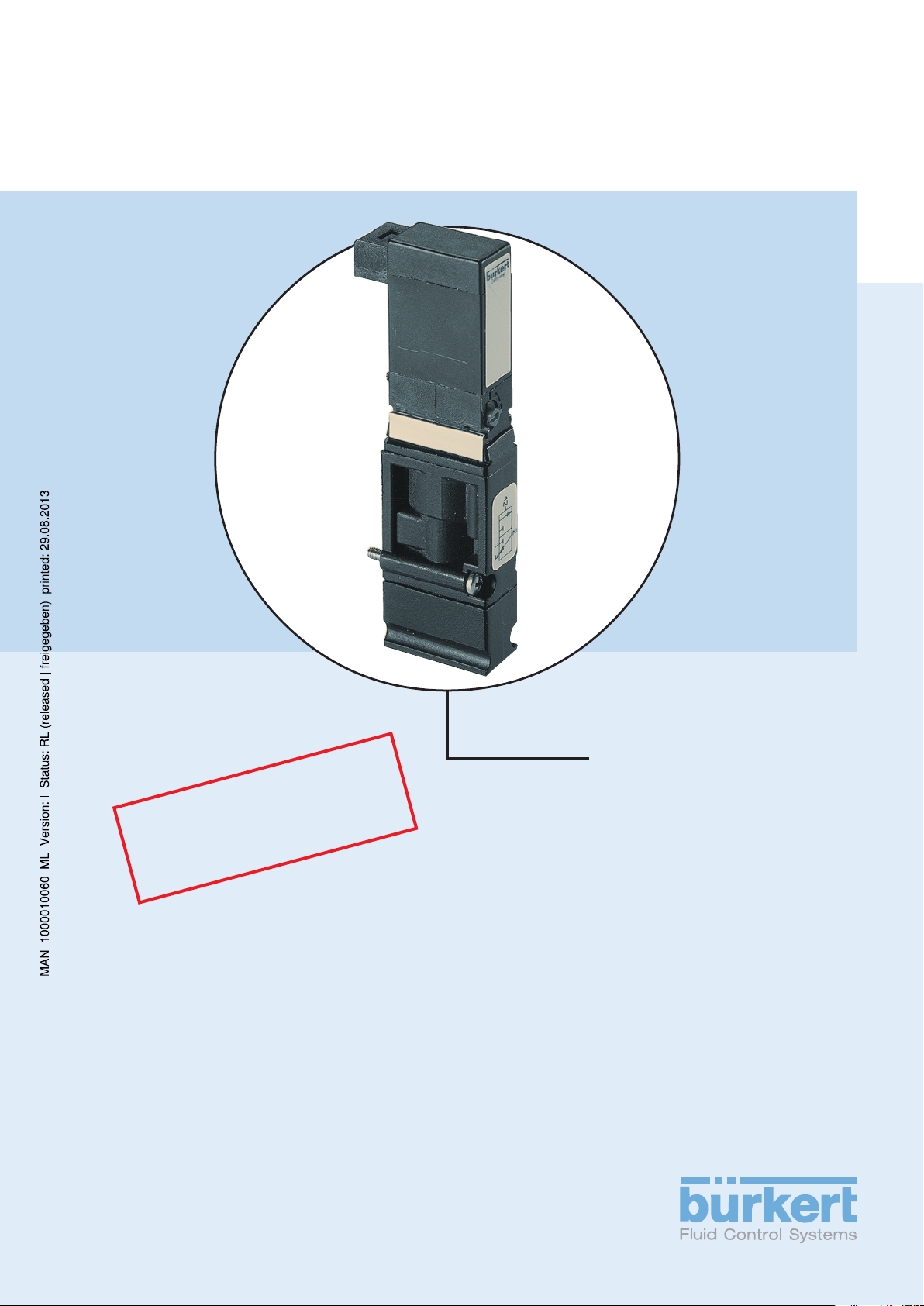
Type 6524 / 6525
3/2- or 5/2-way solenoid valve
for pneumatic systems
3/2- bzw. 5/2-Wege-Magnetventil
für Pneumatik
Electrovanne 3/2 resp. 5/2 voies
pour pneumatique
Page 2

We reserve the right to make technical changes without notice.
Technische Änderungen vorbehalten.
Sous resérve de modification techniques.
© 2000 Bürkert Werke GmbH & Co. KG
Operating Instructions 0512/06_EU-ML_00804310
Page 3
Contents of the Operating Instructions for
Voltage 12V or 24V
UL / UR valid with
class 2 power supply only
3/2- or 5/2-way-solenoid valve
Type 6524 / 6525
GENERAL NOTES........................................................................................................................................................................................................................... 3
Symbols................................................................................................................................................................................................................................................. 4
General safety notes
Safety notes for the valve
Scope of delivery
............................................................................................................................................................................................................ 4
............................................................................................................................................................................................... 5
....................................................................................................................................................................................................................... 6
Warranty conditions
................................................................................................................................................................................................................ 6
TECHNICAL DESCRIPTION........................................................................................................................................................................................... 7
Valve Construction .................................................................................................................................................................................................................. 8
Technical data of the valves Type 6524 / 6525
Inscription example
.............................................................................................................................................................................................................. 10
.................................................................................................................................... 9
INSTALLATION, COMMISSIONING AND MAINTENANCE......................................................................................... 11
Installation ........................................................................................................................................................................................................................................ 12
Measures to be taken before putting into service
Faults
Maintenance
Accessories
........................................................................................................................................................................................................................................................ 16
.................................................................................................................................................................................................................................. 17
.................................................................................................................................................................................................................................. 17
......................................................................................................................... 16
6524/6525 - 1
Page 4
C
ONTENTS
english
2 - 6524/6525
Page 5
GENERAL NOTES
G
ENERAL NOTES
english
Symbols................................................................................................................................................................................................................................................. 4
General Safety notes
Safety notes for the valve
Scope of delivery
Warranty conditions
............................................................................................................................................................................................................ 4
............................................................................................................................................................................................... 5
....................................................................................................................................................................................................................... 6
................................................................................................................................................................................................................ 6
6524/6525 - 3
Page 6

G
ENERAL NOTES
Symbols
In these Operating Instructions, the following symbols are used:
Indicates a working step that you will have to carry out
ATTENTION!
NOTE Indicates important additional information, tips and recommendations.
Indicates information which must be followed. Failure to do this could endanger your
health or the functionality of the device
english
General Safety notes
To ensure that the device will function correctly, and have a long service life, please comply with the
information in these Operating Instructions, as well as with the application conditions and additional data
given in the Type 6524 and Typ 6525 data sheets:
• When planning the application of the device, and during its operation, observe the general technical
rules!
• Installation and maintenance work are only allowed by specialist personnel using suitable tools!
• Observe the relevant accident prevention and safety regulations applicable for electrical equipment
throughout the operation, maintenance and repair of the device!
• Always switch off the voltage supply before working on the system!
• Note that lines and valves must not be unscrewed from systems that are under pressure!
• Take suitable measures to prevent unintentional operation or impermissible impairment!
• After interruption of the electrical or pneumatic supply, make sure the process is restarted in a welldefined, controlled manner!
• If these instructions are ignored, no liability will be accepted from our side, and the guarantee on the
device and on accessories will become invalid!
4 - 6524/6525
Page 7

Safety notes for the valve
• Keep to standard engineering rules in planning the use of and operating the device.
• Take suitable precautions to prevent inadvertent operation or damage by unauthorized action.
• Note that in systems under pressure, piping and valves may not be loosened.
0 bar, psi, kPa
G
ENERAL NOTES
english
Fig.: Fluid connection
• Always switch off the power supply before intervening in the system!
Fig.: Assembly without voltage applied
• To avoid pressure drop on switching, make the volume of the pressure supply as large as
possible!
• The device shall only be operated on direct current .
• Risk of injury!
In continuous operation, the coil can become very hot!
6524/6525 - 5
Page 8

G
ENERAL NOTES
Scope of delivery
Immediately after receipt of the goods, make sure the contents are undamaged and agree with the scope
of delivery stated on the packing slip.
In case of irregularities, contact your local Bürkert branch or our customer service department:
english
Warranty conditions
Bürkert Fluid Control Systems
Service Department
Chr.-Bürkert-Str. 13-17
D-76453 Ingelfingen
Tel.: (07940) 10-111, Fax: (07940) 10-448
eMail: info@de.buerkert.com
This document contains no warranty statements. In this connection we refer to our general sales and
business conditions.
A prerequisite for validity of the warranty ist unse of the device as intended with observance of the
specified conditions of use.
ATTENTION!
The warranty covers only faultless condition of the 3/2 or 5/2-way-solenoid valve Type
6524 / 6525. No liability will be accepted for consequential damage of any kind that
may arise from failure or malfunctioning of the device.
6 - 6524/6525
Page 9

T
ECHNICAL DESCRIPTION
TECHNICAL DESCRIPTION
english
Valve Construction .................................................................................................................................................................................................................. 8
Technical data of the valves Type 6524 / 6525
Inscription example
.............................................................................................................................................................................................................. 10
.................................................................................................................................. 9
6524/6525 - 7
Page 10

T
ECHNICAL DESCRIPTION
Valve Construction
english
Fig: 3/2-way-solenoid valve for pneumatic systems
Type 6524
• Automation systems are increasingly used in all areas where control duties are to be performed. The
valves form thereby the interface between electronics and pneumatics.
• The valves Type 6524 and 6525 consist of a pilot rocker solenoid valve of Type 6104 and a pneumatic
seat valve. Pilot valve and housing are clipped together. The working principle enables the switching of
high pressures at low power consumption and with short switching times.
• The valves can be connected in series and provided with rear plug connector mainly for valve islands
(types 8640 or 8644) and with front connector lugs mainly on valve blocks for operating pneumatic
drives.
• The pilot valves are provided as standard with a manual actuator.
Fig.: 5/2-way-solenoid valve for pneumatic systems
Type 6525
8 - 6524/6525
Page 11

Technical data of the valves Type 6524 / 6525
• Casing material PA (polyamide)
• Sealing materials FKM , NBR and PUR
• Media compressed air oiled, oil-free,
dry neutral gas
• Media temperature -10 to +50 °C
• Ambient temperature -10 to +55 °C
• Pipe connection Flange
• Pneumatic modules MP11
• Supply connection G 1/4, NPT 1/4
1 (P), 3 (R), 5 (S) plug coupling, Ø 10 mm
T
ECHNICAL DESCRIPTION
• Working connection plug coupling
2 (A), 4 (B) Ø 6 mm, M5, M7
• Flow rate Q
• Operating voltage 24 V DC
• Voltage tolerance ± 10%
• Rated power 1 W
• Nominal mode of operation continuous operation (100 % duty cycle)
• Electrical connection rectangular plug with
on valve 5,08 mm grid
on valve island integral plug socket
on valve block rectangular plug connector
• Protection type IP 40 with rectangular plug connector
• Fitting position any, preferably drive on top
• Manual actuation standard
• Protection class 3 to VDE 0580
• Switching times [ms] measured at valve output at 6 bar and +20 °C
(see Data sheet) opening pressure development 0 to 90%
Nn
Air 300 l/min
closing pressure drop 100 to 10%
english
6524/6525 - 9
Page 12

T
ECHNICAL DESCRIPTION
Inscription of valves
Nominal size
Circuit function
Id. No.
Voltage (±10 %) - Power
Type
english
Pressure range
Fig.: Inscription example
10 - 6524/6525
Page 13
I
NSTALLATION
, C
OMMISSIONING AND MAINTENANCE
INSTALLATION,
COMMISSIONING AND
MAINTENANCE
Installation ........................................................................................................................................................................................................................................ 12
Measures to be taken before putting into service
Faults
Maintenance
Asseccories
...................................................................................................................................................................................................................................................... 16
.................................................................................................................................................................................................................................. 17
.................................................................................................................................................................................................................................. 17
......................................................................................................................... 16
english
6524/6525 - 11
Page 14

I
NSTALLATION
, C
Installation
Circuit function
OMMISSIONING AND MAINTENANCE
C 3/2--way-solenoid valve, servo-controlled
Pressure inlet 1 closed when de-energiesed, outlet 2 vented.
D 3/2-way-solenoid valve, servo-controlled
Pressure inlet 1 is connected to outlet 2 when de-energiesed.
english
H 5/2-way-solenoid valve, servo-controlled
Pressure inlet1 is connected to outlet 2 when de-energised, outlet 4 vented.
Cleaning pipes
Clean pipes before starting assembly to ensure reliable operation of the system.
Fit a dirt collector if necessary to protect against faults.
Assembly position
Can be mounted in any position, preferably with the magnetic system at the top.
Preffered
direction
Fig.: Assembly position
Media
• filtered compressed air (max. particle size 5 µm), preferably non-oiled, dry
• operation is possible with oiled air
• sealing material NBR, FKM and PUR
• permissible temperature medium max. + 50 ° C
NOTE
12 - 6524/6525
ambient max. + 55 ° C
Operate valve at temperatures below O°C only with dry air.
Page 15

I
NSTALLATION
, C
OMMISSIONING AND MAINTENANCE
Connections
Interventions must only be made by technical personnel and with suitable tools.
Always switch off the power supply before working on the system.
Fit a dirt collector if necessary to protect against faults.
Ensure compliance of the operating conditions with the performance data of the unit.
Avoid pressure build-up in the exhaust air ducts by large silencers.
ATTENTION!
Pipes or valves in systems under pressure must not be disconnected!
Electrical connection
Stranded conductor
connection
Fig.: Connection possibilities of type 6104 pilot valves
english
Circular connectorRectangular connector
Servo control valve Type 6104
Read the voltage, electrical power, type of protection and current from the rating plate!
voltage tolerance ±10 %
With 100% duty cycle and maximum ambient temperature the coil heats up
in the single version to approx. + 105 °C
in a block to approx. + 120 °C
NOTE
Ensure a long service life for the pilot valve with 5µ filtering.
ATTENTION!
Note the voltage! Fit a rectifier in series without fail for alternating voltage!
6524/6525 - 13
Page 16

I
NSTALLATION
Manual override
To operate the valve manually, turn the manual override by 90° in the direction of the arrow.
, C
OMMISSIONING AND MAINTENANCE
english
Fig.: Setting the manual mode
Fluid connection
0AUTO
1/P 2/A C
2/A 3/R D
1
1/P 4/A
2/B 3/S
(Symb. show the
zero position)
H
X* Pilot control
exhaust
X*
3/R
2/A
1/P
Fig.: Fluid connection (Valve- Type 6524)
NOTE
Lay out the pressure supply to have as large a volume as possible!
X*
5/R
4/A
1/P
2/B
3/S
Fig.: Fluid connection (Valve- Type 6525)
14 - 6524/6525
Page 17

Mounting the valve
30 Ncm
I
NSTALLATION
, C
OMMISSIONING AND MAINTENANCE
20 Ncm
Fig.: Mounting the valve
english
30 Ncm
20 Ncm
6524/6525 - 15
Page 18
I
NSTALLATION
, C
OMMISSIONING AND MAINTENANCE
Measures to be taken before putting into service
Check all connections, voltages and the operational pressure!
Ensure that the max. operational conditions (see rating plate) will not be exceeded!
Unlock the manual actuator for electrical operation!
Faults
Fault Possible cause Correction
english
Valves does
not switch
Valves switch
with a delay, or
exhaust
through the
venting ports
Operational voltage too low or
not present
Manual override not in neutral
position
Compressed air supply not
available or insufficient
Compressed air supply not
available or insufficient
Valves are not in the starting
position (without current)
during pressure build-up
Insufficient venting of the
exhaust channels due to
silencers that are too small or
are soiled (backpressure)
Check the electrical supply connections.
Ensure that the electrical power supply is the same as
that specified on the rating plate.
Set the manual override to the zero position.
Carry out the dimensioning of the compressed air
connection with volumes as large as possible (including
that of upstream pressure regulators, service units, cutoff valves etc.).
Carry out the dimensioning of the compressed air
connection with volumes as large as possible (including
that of upstream pressure regulators, service units, cutoff valves etc.).
Apply pressure to the valve block before you switch the
valves!
Use silencers or expansion channels with sufficient
dimensions.
Clean soiled silencers.
16 - 6524/6525
Impurities or foreign matter in
the pilot valve or main valve
Blast through the exhaust channels with pulsed
compressed air, to blow out impurities.
Install a new pilot or main valve if these measures bring
no improvement.
Page 19

Maintenance
The valves are maintenance-free if operated according to the directions given in these instructions.
Accessories
• Rectangular plug connector with 3 m cable (133 486 F)
• Rectangular plug connector with 300 mm FEP flexible conductor (644 068 N)
I
NSTALLATION
, C
OMMISSIONING AND MAINTENANCE
english
• Rectangular plug connector with 2 individual contacts (644 067 D)
NOTE
Wearing parts on request!
6524/6525 - 17
Page 20

I
NSTALLATION
english
, C
OMMISSIONING AND MAINTENANCE
18 - 6524/6525
Page 21

I
Voltage 12V or 24V
UL / UR valid with
class 2 power supply only
NHALT
Inhaltsverzeichnis
der Betriebsanleitung
3/2- bzw. 5/2-Wege-Magnetventil
Typ 6524 / 6525
ALLGEMEINE HINWEISE.................................................................................................................................................................................................. 21
Darstellungsmittel................................................................................................................................................................................................................... 22
Allgemeine Sicherheitshinweise
Sicherheitshinweise für das Ventil
.......................................................................................................................................................................... 22
..................................................................................................................................................................... 23
deutsch
Lieferumfang
Garantiebestimmungen
.................................................................................................................................................................................................................................. 24
................................................................................................................................................................................................... 24
TECHNISCHE BESCHREIBUNG ......................................................................................................................................................................... 25
Ventilaufbau.............................................................................................................................................................................................................................. 26
Technische Daten der Ventile Typ 6524 / 6525
Beschriftungsbeispiel
........................................................................................................................................................................................................ 28
................................................................................................................................. 27
MONTAGE, INBETRIEBNAHME UND WARTUNG..................................................................................................................... 29
Montage .............................................................................................................................................................................................................................................. 30
Maßnahmen vor Inbetriebnahme
Störungen
Wartung
Zubehör
......................................................................................................................................................................................................................................... 34
............................................................................................................................................................................................................................................... 35
............................................................................................................................................................................................................................................... 35
........................................................................................................................................................................ 34
6524/6525 - 19
Page 22

deutsch
I
NHALT
20 - 6524/6525
Page 23

A
LLGEMEINE HINWEISE
ALLGEMEINE HINWEISE
Darstellungsmittel................................................................................................................................................................................................................... 22
deutsch
Allgemeine Sicherheitshinweise
Sicherheitshinweise für das Ventil
Lieferumfang
Garantiebestimmungen
.................................................................................................................................................................................................................................. 24
................................................................................................................................................................................................... 24
.......................................................................................................................................................................... 22
..................................................................................................................................................................... 23
6524/6525 - 21
Page 24

A
LLGEMEINE HINWEISE
Darstellungsmittel
In dieser Betriebsanleitung werden folgende Darstellungsmittel verwendet:
markiert einen Arbeitsschritt, den Sie ausführen müssen.
ACHTUNG!
HINWEIS
kennzeichnet Hinweise, bei deren Nichtbeachtung Ihre Gesundheit oder
die Funktionsfähigkeit des Gerätes gefährdet ist.
kennzeichnet wichtige Zusatzinformationen, Tipps und Empfehlungen.
Allgemeine Sicherheitshinweise
deutsch
Bitte beachten Sie die Hinweise dieser Betriebsanleitung sowie die Einsatzbedingungen und zulässigen
Daten gemäß den Datenblättern Typ 6524 und Typ 6525, damit das Gerät einwandfrei funktioniert und
lange einsatzfähig bleibt.
• Halten Sie sich bei der Einsatzplanung und dem Betrieb des Gerätes an die allgemeinen Regeln der
Technik!
• Installations- und Wartungsarbeiten dürfen nur durch Fachpersonal und mit geeignetem Werkzeug
erfolgen.
• Beachten Sie die geltenden Unfallverhütungs- und Sicherheitsbestimmungen für elektrische Geräte
während des Betriebes, der Wartung und der Reparatur des Gerätes!
• Schalten Sie vor Eingriffen in das System in jedem Fall die Spannung ab!
• Beachten Sie, dass in Systemen, die unter Druck stehen,Leitungen und Ventile nicht gelöst werden
dürfen.
• Treffen Sie geeignete Maßnahmen, um unbeabsichtigtes Betätigen oder unzulässige Beeinträchtigung
auszuschließen!
• Gewährleisten Sie nach einer Unterbrechung der elektrischen oder pneumatischen Versorgung einen
definierten und kontrollierten Wiederanlauf des Prozesses!
• Bei Nichtbeachtung dieser Hinweise und unzulässigen Eingriffen in das Gerät entfällt jegliche Haftung unsererseits, ebenso erlischt die Garantie auf Geräte und Zubehörteile!
22 - 6524/6525
Page 25

Sicherheitshinweise für das Ventil
• Halten Sie sich bei Einsatzplanung und Betrieb des Gerätes an die einschlägigen, allgemein
anerkannten sicherheitstechnischen Regeln.
• Treffen Sie geeignete Maßnahmen, um unbeabsichtigtes Betätigen oder unzulässige Beeinträchtigungen auszuschließen.
• Beachten Sie, dass in Systemen, die unter Druck stehen, Leitungen und Ventile nicht
gelöst werden dürfen.
A
LLGEMEINE HINWEISE
0 bar, psi, kPa
Bild: Fluidischer Anschluss
• Schalten Sie vor Eingriffen in das System in jedem Fall die Spannung ab!
Bild: Spannungsfreie Montage
deutsch
• Führen Sie die Druckversorgung möglichst großvolumig aus, um Druckabfall beim Schalten
zu vermeiden!
• Das Gerät darf nur mit Gleichstrom betrieben werden.
• Verletzungsgefahr!
Bei Dauerbetrieb kann die Spule sehr heiss werden!
6524/6525 - 23
Page 26

A
LLGEMEINE HINWEISE
Lieferumfang
Überzeugen Sie sich unmittelbar nach Erhalt der Sendung, dass der Inhalt nicht beschädigt ist und mit
dem auf dem beigelegten Packzettel angegebenen Lieferumfang übereinstimmt.
Bei Unstimmigkeiten wenden Sie sich bitte umgehend an Ihre Bürkert-Niederlassung oder an unseren
Kundenservice:
Garantiebestimmungen
Bürkert Steuer- und Regelungstechnik
Service-Abteilung
Chr.-Bürkert-Str. 13-17
D-76453 Ingelfingen
Tel.: (07940) 10-111, Fax: (07940) 10-448
eMail: info@de.buerkert.com
deutsch
Diese Druckschrift enthält keine Garantiezusagen. Wir verweisen hierzu auf unsere allgemeinen Verkaufs- und Geschäftsbedingungen.
Voraussetzung für die Garantie ist der bestimmungsgemäße Gebrauch des Gerätes unter Beachtung
der spezifizierten Einsatzbedingungen.
ACHTUNG!
Die Gewährleistung erstreckt sich nur auf die Fehlerfreiheit der 3/2 bzw. 5/2-WegeMagnetventile Typ 6524 / 6525. Es wird keine Haftung übernommen für Folgeschäden
jeglicher Art, die durch Ausfall oder Fehlfunktion des Gerätes entstehen könnten.
24 - 6524/6525
Page 27

T
ECHNISCHE BESCHREIBUNG
TECHNISCHE
BESCHREIBUNG
deutsch
Ventilaufbau.................................................................................................................................................................................................................................... 26
Technische Daten der Ventile Typ 6524 / 6525
Beschriftungsbeispiel
........................................................................................................................................................................................................ 28
................................................................................................................................. 27
6524/6525 - 25
Page 28

T
ECHNISCHE BESCHREIBUNG
Ventilaufbau
deutsch
Bild: 3/2-Wege-Magnetventil für Pneumatik Typ 6524 Bild: 5/2-Wege-Magnetventil für Pneumatik Typ 6525
• Automatisierungssysteme finden zunehmend Einsatz in allen Bereichen wo Steuerungs- und
Regelungsaufgaben zu bewältigen sind. Ventile bilden dabei die Schnittstelle zwischen der Elektronik
und Pneumatik.
• Die Ventile vom Typ 6524 / 6525 bestehen aus einem Vorsteuer-Wippenmagnetventil vom Typ 6104
und einem Pneumatiksitzventil. Vorsteuerventil und Gehäuse sind miteinander verklammert. Das
Wirkprinzip erlaubt das Schalten hoher Drücke bei geringer Leistungsaufnahme und mit kurzen
Schaltzeiten.
• Die Ventile sind anreihbar und mit Steckeranschluss hinten vorzugsweise für Ventilinseln (Typen
8640 oder 8644) und mit Steckerfahnen vorn vorzugsweise auf Ventilblöcken zur Ansteuerung pneumatischer Antriebe einsetzbar.
• Die Vorsteuerventile sind serienmäßig mit einer Handbetätigung ausgestattet.
26 - 6524/6525
Page 29

Technische Daten der Ventile Typ 6524 / 6525
• Gehäusewerkstoff PA (Polyamid)
• Dichtwerkstoffe FKM , NBR und PUR
• Medien Druckluft geölt, ölfrei, trocken
neutrale Gase
• Medientemperatur -10 bis +50 °C
• Umgebungstemperatur -10 bis +55 °C
• Leitungsanschluss Flansch
• Pneumatikmodule MP11
• Versorgungsanschluss G 1/4, NPT 1/4
1 (P), 3 (R), 5 (S) Steckkupplung, Ø 10 mm
• Arbeitsanschluss Steckkupplung
2 (A), 4 (B) Ø 6 mm, M5, M7
T
ECHNISCHE BESCHREIBUNG
• Durchfluss Q
• Betriebsspannung 24 V DC
• Spannungstoleranz ± 10%
• Nennleistung 1 W
• Nennbetriebsart Dauerbetrieb (100 % ED)
• Elektrischer Anschluss Rechteckstecker mit
am Ventil Raster 5,08 mm
auf Ventilinsel integrierte Steckerbuchse
auf Ventilblock Rechtecksteckverbinder
• Schutzart IP 40 mit Rechtecksteckverbinder
• Einbaulage beliebig, vorzugsweise Antrieb nach oben
• Handbetätigung serienmäßig
• Schutzklasse 3 nach VDE 0580
• Schaltzeiten [ms] Messung am Ventilausgang bei 6 bar und +20 °C
(siehe Datenblatt) Öffnen Druckaufbau 0 bis 90%
Nn
Luft 300 l/min
Schließen Druckabbau 100 bis 10%
deutsch
6524/6525 - 27
Page 30

T
ECHNISCHE BESCHREIBUNG
Beschriftung der Ventile
Nennweite
Wirkungsweise
Bestell-Nr.
Spannung (±10 %) - Leistung
Druckbereich
deutsch
Ty p
Bild: Beschriftungsbeispiel
28 - 6524/6525
Page 31

M
ONTAGE
, I
NBETRIEBNAHME UND WARTUNG
MONTAGE
INBETRIEBNAHME
UND WARTUNG
deutsch
Montage .............................................................................................................................................................................................................................................. 30
Maßnahmen vor Inbetriebnahme
Störungen
Wartung
Zubehör
......................................................................................................................................................................................................................................... 34
............................................................................................................................................................................................................................................... 35
............................................................................................................................................................................................................................................... 35
........................................................................................................................................................................ 34
6524/6525 - 29
Page 32

M
ONTAGE
Montage
deutsch
, I
NBETRIEBNAHME UND WARTUNG
Wirkungsweise
C 3/2-Wege-Magnetventil, vorgesteuert
In Ruhestellung Druckanschluss 1 gesperrt, Ausgang 2 entlüftet.
D 3/2-Wege-Magnetventil, vorgesteuert
In Ruhestellung Druckanschluss 1 mit Ausgang 2 verbunden.
H 5/2-Wege-Magnetventil, vorgesteuert
In Ruhestellung Druckanschluss 1 mit Ausgang 2 verbunden,
Ausgang 4 entlüftet.
Reinigung der Rohrleitungen
Reinigen Sie vor Beginn der Montage die Rohrleitungen, um den zuverlässigen Betrieb Ihrer Anlage
sicherzustellen.
Schalten Sie gegebenenfalls zum Schutz vor Störungen einen Schmutzfänger vor.
Einbaulage
Die Einbaulage ist beliebig. Montieren Sie die Ventile vorzugsweise mit dem Antrieb nach oben.
Vorzugsrichtung
Bild: Einbaulage
Medien
• gefilterte Druckluft (Partikelgröße max. 5 µm), vorzugsweise ungeölt, trocken
• Betrieb mit geölter Luft ist möglich
• Dichtwerkstoff NBR, FKM und PUR
• zulässige Temperatur Medium max. + 50 ° C
HINWEIS
30 - 6524/6525
Umgebung max. + 55 ° C
Ventil bei Temperaturen unter 0 °C nur mit trockener Luft betreiben.
Page 33

M
ONTAGE
, I
NBETRIEBNAHME UND WARTUNG
Anschlüsse
Eingriffe dürfen nur durch Fachpersonal und mit geeignetem Werkzeug erfolgen.
Schalten Sie vor Eingriffen in das System in jedem Fall die Spannung ab.
Schalten Sie gegebenenfalls zum Schutz vor Störungen einen Schmutzfänger vor.
Achten Sie auf Übereinstimmung der Betriebsbedingungen mit den Leistungsdaten des Gerätes.
Vermeiden Sie Staudrücke in den Abluftkanälen durch großvolumige Schalldämpfer.
ACHTUNG!
In Systemen, die unter Druck stehen, dürfen Leitungen oder Ventile nicht gelöst werden!
Elektrischer Anschluss
Litzenanschluss RundsteckerRechteckstecker
Bild: Anschlussmöglichkeiten der Vorsteuerventile Typ 6104
deutsch
Vorsteuerventil Typ 6104
Entnehmen Sie Spannung, elektrische Leistung, Schutz- und Stromart dem Typenschild!
Spannungstoleranz ±10 %
Bei 100 % Einschaltdauer und maximaler Umgebungstemperatur erwärmt sich die Spule
im Einzelaufbau auf ca. + 105 °C
im Block auf ca. + 120 °C
HINWEIS
Sorgen Sie durch 5µ-Filterung für eine lange Lebensdauer des Vorsteuerventils.
ACHTUNG!
Beachten Sie die Spannung! Schalten Sie bei Wechselspannung unbedingt einen
Gleichrichter vor!
6524/6525 - 31
Page 34

M
ONTAGE
, I
NBETRIEBNAHME UND WARTUNG
Handbetätigung
Drehen Sie zur manuellen Betätigung des Ventils die Handbetätigung um 90° in Pfeilrichtung.
deutsch
Bild: Einstellen des Handmodus
Fluidischer Anschluss
0AUTO
1/P 2/A C
2/A 3/R D
1
1/P 4/A
2/B 3/S
(Symb. zeigen
Nullstellung)
H
X* Vorsteuerabluft
X*
3/R
2/A
1/P
Bild: Fluidischer Anschluss (Ventil - Typ 6524)
HINWEIS
Druckversorgung möglichst großvolumig ausführen!
X*
5/R
4/A
1/P
2/B
3/S
Bild: Fluidischer Anschluss (Ventil - Typ 6525)
32 - 6524/6525
Page 35

Montage des Ventils
20 Ncm
30 Ncm
M
ONTAGE
, I
NBETRIEBNAHME UND WARTUNG
Bild: Montage des Ventils
20 Ncm
30 Ncm
deutsch
6524/6525 - 33
Page 36

M
ONTAGE
, I
NBETRIEBNAHME UND WARTUNG
Maßnahmen vor der Inbetriebnahme
Überprüfen Sie Anschlüsse, Spannung und Betriebsdruck!
Beachten Sie, dass max. Betriebsdaten (siehe Typenschild) nicht überschritten werden!
Entriegeln Sie bei elektrischem Betrieb die Handbetätigung!
Störungen
Störung mögliche Ursache Behebung
deutsch
Ventile
schalten nicht
Ventile
schalten
verzögert oder
blasen an den
Entlüftungsanschlüssen ab
Keine oder nicht
ausreichende
Betriebsspannung
Handbetätigung nicht in
neutraler Stellung
Druckversorgung nicht
ausreichend oder nicht
vorhanden
Druckversorgung nicht
ausreichend oder nicht
vorhanden
Ventile sind während des
Druckaufbaus nicht in
Grundstellung (stromlos)
keine ausreichende
Entlüftung der Abluftkanäle
durch zu kleine oder
verschmutzte
Geräuschdämpfer
(Rückdrücke);
Überprüfen Sie den elektrischen Anschluss.
Stellen Sie die Betriebsspannung laut Typenschild
sicher.
Bringen Sie die Handbetätigung in Null-Stellung.
Führen Sie die Druckversorgung möglichst großvolumig
aus (auch bei vorgeschalteten Geräten wie
Druckreglern, Wartungseinheiten, Absperrventilen usw.).
Führen Sie die Druckversorgung möglichst großvolumig
aus (auch bei vorgeschalteten Geräten wie
Druckreglern, Wartungseinheiten, Absperrventilen usw.).
Beaufschlagen Sie den Ventilblock mit Druck, bevor Sie
die Ventile schalten!
Verwenden Sie entsprechend groß dimensionierte
Geräuschdämpfer bzw. Expansionsgefäße.
Reinigen Sie verschmutzte Geräuschdämpfer.
34 - 6524/6525
Verunreinigungen bzw.
Fremdkörper im Vorsteueroder Hauptventil.
Beaufschlagen Sie die Abluftkanäle mit impulsartigem
Druck, um die Verunreinigungen auszublasen
Bauen Sie ein neues Vorsteuer- bzw. Hauptventil ein,
wenn diese Maßnahme keinen Erfolg bringt.
Page 37

Wartung
Bei Betrieb entsprechend den in dieser Anleitung gegebenen Anweisungen arbeiten die Ventile wartungsfrei.
Zubehör
M
ONTAGE
• Rechtecksteckverbinder mit 3 mKabel (133 486 F)
, I
NBETRIEBNAHME UND WARTUNG
• Rechtecksteckverbinder mit 300 mm FEP-Litzen (644 068 N)
• Rechtecksteckverbinder mit 2 Einzelkontakten (644 067 D)
HINWEIS
Verschleißteile auf Anfrage!
deutsch
6524/6525 - 35
Page 38

deutsch
M
ONTAGE
, I
NBETRIEBNAHME UND WARTUNG
36 - 6524/6525
Page 39

S
Voltage 12V or 24V
UL / UR valid with
class 2 power supply only
OMMAIRE
Table de matieres
Instructions de service
3/2- resp. 5/2 voies Elektrovanne
Type 6524 / 6525
CONSIGNES GENERALES............................................................................................................................................................................................ 39
Représentation .......................................................................................................................................................................................................................... 40
Consignes générales de sécurité
Consignes de sécurité relatives aux vannes
...................................................................................................................................................................... 40
..................................................................................................................................... 41
Couverture de livraison
Clauses de garantie
.................................................................................................................................................................................................. 42
............................................................................................................................................................................................................ 42
DESCRIPTION TECHNIQUES .................................................................................................................................................................................... 43
Construction de la vanne.............................................................................................................................................................................................. 44
Characteristiques techniques des vannes du type 6524 / 6525
Exemple d’inscription
......................................................................................................................................................................................................... 46
................................................................................ 45
MONTAGE, MISE EN SERVICE ET ENTRETIEN......................................................................................................................... 47
Montage ................................................................................................................................................................................................................................................ 48
Précautions à prendre avant la mise en service
Dérangements
Entretien
Accessoires
............................................................................................................................................................................................................................ 52
............................................................................................................................................................................................................................................. 53
.................................................................................................................................................................................................................................. 53
............................................................................................................................ 52
français
6524/6525 - 37
Page 40

S
OMMAIRE
français
38 - 6524/6525
Page 41

C
ONSIGNES GENERALES
CONSIGNES GENERALES
Représentation .......................................................................................................................................................................................................................... 40
Consignes générales de sécurité
Consignes de sécurité relatives aux vannes
Couverture de livraison
Clauses de garantie
.................................................................................................................................................................................................. 42
............................................................................................................................................................................................................ 42
...................................................................................................................................................................... 40
..................................................................................................................................... 41
français
6524/6525 - 39
Page 42

C
ONSIGNES GENERALES
Représentation
Vous rencontrerez les symboles de précaution suivants dans cette instruction de service:
Ceux-ci définissent une tâche que vous devez effectuer.
ATTENTION!
REMARQUE
Rappelle des consignes dont la non observation est susceptible d’entraîner des
dommages corporels ou de porter atteinte au fonctionnement de l’appareil.
Rappelle les informations supplémentaires importantes, les astuces et
recommandations.
Consignes générales de sécurité
Respectez scrupuleusement les consignes de cette instruction de service, de même que les conditions
d’emploi et les valeurs admissibles conformément à la feuille de données, de façon à ce que l’appareil
fonctionne parfaitement et demeure longtemps opérationnel.
français
• Pour les modalités d’emploi et de fonctionnement de l’appareil, cantonnez-vous aux règles générales de
technologie!
• Les travaux d’installation et de maintenance ne doivent être effectués que par du personnel spécialiste
et en utilisant l’outillage approprié.
• Respectez les prescriptions de sécurité et de prévention en vigueur contre les accidents spécifiques à
l’appareillage électrique au cours de la mise en oeuvre, de l’entretien et des réparations de l’appareil!
• Couper systématiquement la tension de l’installation avant toute intervention!
• Veillez à ne pas desserrer ou démonter les conduites et les vannes de circuits soumis à pressurisation.
• Entourez-vous de toutes les mesures appropriées permettant d’éviter les manipulations involontaires ou
les interventions non autorisées!
• Après toute interruption d’alimentation électrique ou pneumatique, assurez-vous de garantir un
redémarrage de processus défini et contrôlé!
• Le non-respect de telles consignes et des interventions non autorisées sur l’appareil nous exonère de
toute responsabilité et exclut également toute invocation à garantie sur les appareils et les pièces
détachées!
40 - 6524/6525
Page 43

Consignes de sécurité relatives aux vannes
• Pour tout ce qui concerne l’affectation et l’exploitation de l’appareil, conformez-vous aux règles
techniques de sécurité générales et en vigueur qui s’y rapportent.
• Prenez toutes les mesures appropriées destinées à exclure les manipulations involontaires ou
interventions non autorisées.
• Veillez à ne pas desserrer ou démonter les conduites et vannes des circuits soumis à pressurisation.
0 bar, psi, kPa
C
ONSIGNES GENERALES
Fig.: Raccordement fluidique
• Couper systématiquement la tension avant toute intervention sur le système!
Fig.: Montage sans tension
• Ouvrir si possible en grand l’alimentation pressurisation afin d’éviter les chutes de pression!
français
• L’appareil ne doit être alimenté qu’en courant continu.
• Risque de dommages corporels!
Après une période de fonctionnement ininterrompue, la bobine devient très chaude!
6524/6525 - 41
Page 44

C
ONSIGNES GENERALES
Couverture de livraison
Dès réception de la marchandise, assurez-vous immédiatement que le contenu des colis n’a pas été
endommagé en cours de transport et que le contenu de l’envoi correspond bien au bordereau
d’accompagnement. En présence de non conformité, adressez-vous uniquement à notre service clientèle
ou à votre Filiale Bürkert.
Bürkert Technologie de Commande et de Régulation
Clauses de garantie
Division Service
Chr.-Bürkert-Str. 13-17
D-76453 Ingelfingen
Tel.: (07940) 10-111, Fax: (07940) 10-448
eMail: info@de.buerkert.com
Cet imprimé stipule les acceptations de garantie. Nous faisons référence à nos conditions générales de
commercialisation et de vente.
Toute invocation à garantie implique une utilisation de l’appareil conforme aux prescriptions et effectuée
dans le respect des conditions d’emploi spécifiées.
français
ATTENTION!
La garantie s’étend uniquement à la tolérance d’erreur des 3/2 resp. 5/2 voies
electrovannes type 6524 / 6525. Nous déclinons toute responsabilité concernant les
dommages de toute nature induits qui pourraient survenir d’une panne ou d’un
fonctionnement erroné de l’appareil en dehors de cette plage d’utilisation.
42 - 6524/6525
Page 45

D
ESCRIPTION TECHNIQUES
DESCRIPTION TECHNIQUES
Construction de la vanne.............................................................................................................................................................................................. 44
Characteristiques techniques des vannes du type 6524 / 6525
Exemple d’inscription
......................................................................................................................................................................................................... 46
................................................................................ 45
français
6524/6525 - 43
Page 46

D
ESCRIPTION TECHNIQUES
Construction de la vanne
Fig.: Electrovanne 3/2 voies pour application
pneumatique, type 6524
• Les systèmes d’automatisation justifient de plus en plus leur emploi dans tous les domaines où les
français
• Les îlots de vannes de type 6524 et 6525 se composent d’une électrovanne de commande anticipée à
• Les vannes peuvent s’ajouter à la file et, avec raccord par fiche placé derrière, s’utiliser, de préférence,
• Les vannes pilotes sont équipées en série d’une commande manuelle.
Fig.: Electrovanne 5/2 voies pour application
pneumatique, type 6525
fonctions de commande et de régulation doivent être maîtrisées. Au sein de telles applications, les
vannes constituent l’interface de relation entre l’électronique et le pneumatique.
basculement de Type 6104 et d’une vanne de jonction pneumatique. La vanne de commande anticipée
est sertie au corps du bloc. Ce principe de combinaison d’effets permet la commutation sous haute
pression à puissance de consommation réduite et des temps de commutation très courts.
comme îlots de vannes (types 8640 ou 8644) de même qu’avec des languettes enfichables placées
devant, de préférence, sur des blocs de vannes pour commander des entraînements pneumatiques.
44 - 6524/6525
Page 47

D
ESCRIPTION TECHNIQUES
Characteristiques techniques des vannes du type 6524 / 6525
• Matériau boîtier PA (Polyamide)
• Matériaux d’étanchéité FKM , NBR et PUR
• Médiums air pressurisation gras, sec, sèche,
gaz neutres
• Température médium -10 à +50 °C
• Température d’environnement -10 à +55 °C
• Raccord circuit bride
• Modules pneumatiques MP11
• Raccord d'alimentation G 1/4, NPT 1/4
1 (P), 3 (R), 5 (S) couplage par fiche, Ø 10 mm
• Raccord de service couplage par fiche
2 (A), 4 (B) Ø 6 mm, M5, M7
• Düebit Q
• Tension de service 24 V DC
• Tolérance de tension ± 10%
• Puissance nominale 1 W
• Mode d’exploitation nominale continu (100 % ED)
• Raccord électrique fiche carrée avec
• Indice de protection IP 40 avec raccord à fiche carrée
• Position d’intégration au choix, de préférence commande vers le haut
• Commande manuelle de série
• Classe de protection 3 selon VDE 0580
• Temps de commutation [ms] mesure en sortie de vanne à 6 bar et à +20 °C
Nn
sur la vanne grille 5,08 mm
sur îlot de vannes douille à fiche intégrée
sur bloc de vannes connecteur à fiche rectangulaire
(voir fiche technique) ouverture pressurisation de 0 à 90%
air 300 l/min
fermeture dépressurisation de 100 à 10%
français
6524/6525 - 45
Page 48

D
ESCRIPTION TECHNIQUES
Inscription des vannes
Dimension nominale
Fonctionnement
Type
N° id.
Tension (±10 %) - Puissance
Plage de pression
français
Fig.: Exemple d’inscription
46 - 6524/6525
Page 49

M
ONTAGE
, M
ISE EN SERVICE ET ENTRETIEN
MONTAGE,
MISE EN SERVICE ET
ENTRETIEN
Montage .............................................................................................................................................................................................................................................. 48
Précautions à prendre avant la mise en service
Dérangements
Entretien
Accessoires
............................................................................................................................................................................................................................ 52
............................................................................................................................................................................................................................................. 53
.................................................................................................................................................................................................................................. 53
............................................................................................................................ 52
français
6524/6525 - 47
Page 50

M
ONTAGE
, M
Montage
Fonctionnement
ISE EN SERVICE ET ENTRETIEN
C Electrovanne 3/2 voies, à vanne pilote
En position de repos, sortie 1 bloqué, sortie 2 à l’air libre.
D Electrovanne 3/2 voies, à vanne pilote
En position de repos, raccord de pression 1 relié à sortie 2.
H Electrovanne 5/2 voies, à vanne pilote
En position de repos, raccord de pression 1 relié à sortie 2,
sortie 4 à l’air libre.
Nettoyage des conduites
Nettoyer les conduites avant de commencer le montage pour assurer un fonctionnement fiable de votre
français
Monter en amont, le cas échéant, un collecteur d’impuretés comme protection anti-pannes.
Position de montage
Position de montage quelconque, de préférence avec système magnétique en haut.
Fig: Position de montage
installation.
Orientation
préférentielle
Médiums
• Air comprimé filtré (grandeur max. des particules 5 µm), de préférence sans huile, sec
• Le fonctionnement avec de l’air huilé est possible
• Matière du joint NBR, FKM und PUR
• Température admissible fluidesmax. + 50 ° C
REMARQUE
48 - 6524/6525
ambiante max. + 55 ° C
Pour des températures inférieures à 0 °C, le fonctionnement est limité à l’air sec.
Page 51

M
ONTAGE
, M
ISE EN SERVICE ET ENTRETIEN
Raccordements
Des interventions ne doivent être effectuées que par un personnel qualifié équipé de l’outillage
approprié.
Déclencher dans tous les cas la tension avant toute intervention sur le système.
Monter éventuellement un filtre en amont pour prévenir des dérangements.
Veiller à la concordance des conditions d’exploitation avec les caractéristiques de débit de l’appareil.
Eviter les accumulations de pression dans les canaux d’échappement d’air en employant des silencieux
de grand volume.
ATTENTION!
Ne pas démonter des conduites ou des vannes dans des systèmes se trouvant sous
pression!
Raccordement électrique
Raccord par fil torsadé Fiche rondeFiche rectangulaire
Fig.: Possibilités de raccordement des vannes pilotes, type6104
français
Vanne pilote, type 6104
Tension, puissance électrique, type de protection et courant figurent sur la plaque signalétique!
Tolérance de tension ±10 %
En cas de durée d’enclenchement à 100 % et une température ambiante maximale, la bobine s’échauffe
en montage isolé à env. + 105 °C
en bloc à env. + 120 °C
REMARQUE
Assurer une grande longévité de la vanne pilote par un filtrage à 5µ.
ATTENTION!
Veiller à la tension! En tension alternative, monter impérativement un redresseur en
amont!
6524/6525 - 49
Page 52

M
ONTAGE
, M
ISE EN SERVICE ET ENTRETIEN
Actionnement manuel
Pour l’actionnement manuel de la vanne, tourner l’actionnement manuel de 90° dans le sens de la
flèche.
Fig,: Réglage du mode manuel
Raccordement fluidique
français
0AUTO
1/P 2/A C
2/A 3/R D
1
1/P 4/A
2/B 3/S
(Symb. indiquent
position zéro)
H
X* Gaine d’air
d’echappement de
la commande
pilote
X*
3/R
2/A
1/P
Fig.: Raccordement fluidique (Vanne - Type 6524)
REMARQUE
Exécuter l’alimentation en pression le plus largement possible!
X*
5/R
4/A
1/P
2/B
3/S
Fig.: Raccordement fluidique (Vanne - Type 6525)
50 - 6524/6525
Page 53

Montage de la vanne
20 Ncm
30 Ncm
M
ONTAGE
, M
ISE EN SERVICE ET ENTRETIEN
20 Ncm
Fig.: Montage de la vanne
30 Ncm
français
6524/6525 - 51
Page 54

M
ONTAGE
, M
ISE EN SERVICE ET ENTRETIEN
Précautions à prendre avant la mise en service
Vérifier les raccordements, la tension et la pression de service!
Veiller à ce que les données de service maximales (voir plaquette signalétique) ne soient pas
dépassées!
En cas de fonctionnement électrique, déverrouiller l’actionnement manuel!
Dérangements
Panne Cause possible Remède
français
Vannes ne
commutent
pas
Vannes
commutent à
retardement ou
crachent aux
raccords de
purge
Tension de service
insuffisante ou absente
Commande manuelle n'est
pas en position neutre
Alimentation en pression
insuffisante ou absente
Alimentation en pression
insuffisante ou absente
Vannes ne sont pas en
position initiale (sans courant)
pendant l'établissement de la
pression
Purge insuffisante des
canaux d'évacuation d'air par
des silencieux trop petits ou
encrassés (contre-pression)
Vérifier le branchements électrique.
Contrôler la tension de service sur la plaque
signalétique.
Mettre la commande manuelle en position zéro.
Assurer généreusement l'alimentation en pression
(également pour les appareils branchés en amont, tels
que régulateurs de pression, unités d'entretien vannes
d'arrêt etc.).
Assurer généreusement l'alimentation en pression
(également pour les appareils branchés en amont, tels
que régulateurs de pression, unités d'entretien vannes
d'arrêt etc.).
Injecter de la pression dans le bloc avant de mettre les
vannes en circuit!
Utiliser des silencieux ou des vases d'expansion
largement dimensionnés.
Nettoyer les silencieux encrassés.
52 - 6524/6525
Impuretés ou corps étrangers
dans la vanne pilote ou la
vanne principale
Injecter de la pression par impulsions dans les canaux
d'évacuation d'air pour éjecter les impuretés.
Monter une nouvelle vanne pilote ou vanne principale, si
ces mesures sont sans effet.
Page 55

Entretien
Si les instructions figurant dans cette notice sont bien suivies en cours de service, les vannes
fonctionneront sans entretien.
Accessoires
• Connecteur à fiche rectangulaire avec 3 m de cable(133 486 F)
• Connecteur à fiche rectangulaire avec 300 mm de cordon FEP (644 068 N)
M
ONTAGE
, M
ISE EN SERVICE ET ENTRETIEN
• Connecteur à fiche rectangulaire avec 2 contacts séparés (644 067 D)
REMARQUE
Pièces de rechange sur demande!
français
6524/6525 - 53
Page 56

Bürkert Company Locations
Contact addresses / Kontaktadressen
Germany / Deutschland / Allemange
Bürkert Fluid Control System
Sales Centre
Chr.-Bürkert-Str. 13-17
D-74653 Ingelfingen
Tel. + 49 (0) 7940 - 10 91 111
Fax + 49 (0) 7940 - 10 91 448
E-mail: info@de.buerkert.com
International
Contact addresses can be found on the internet at:
Die Kontaktadressen finden Sie im Internet unter:
Les adresses se trouvent sur internet sous :
www.burkert.com
Page 57

 Loading...