

Page 1
Bedienungsanleitung
Manuel d‘utilisation
Operating Instructions
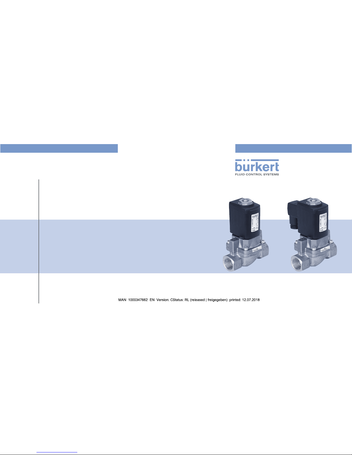
Type 6407
2/2-way solenoid valve
2/2-Wege-Magnetventil
Électrovanne 2/2 voies
Page 2
2
1 OPERATING INSTRUCTIONS
The operating instructions contain important information.
▶ Read the operating instructions carefully and follow the safety
instructions in particular, and also observe the operating conditions.
▶ Operating instructions must be available to each user.
▶ The liability and warranty for the device are void if the operating
instructions are not followed.
1.1 Symbols
▶ Designates an instruction to prevent risks.
→ Designates a procedure which you must carry out.
Warning of injuries:
DANGER!
Imminent danger! Serious or fatal injuries.
WARNING!
Potential danger! Serious or fatal injuries.
CAUTION!
Danger! Minor or moderately severe injuries.
Warns of damage to property:
NOTE!
Contents
1 Operating instructions..................................................................2
2 Intended use ...............................................................................3
3 Basic safety instructions .............................................................. 4
4 Technical data .............................................................................5
5 Installation ................................................................................... 8
6 Maintenance, troubleshooting ...................................................10
7 Spare parts ...............................................................................12
8 Transport, storage, disposal....................................................... 13
english
Page 3

3
2.1 Denition of therm “device”
In these operating instructions, the term “device” always refers to
the solenoid valve Type 6407.
2 INTENDED USE
Incorrect use of the solenoid valve Type 6407 can be dangerous
to people, nearby equipment and the environment.
▶ The device is designed to control, shut o and meter neutral media
up to a viscosity of 21mm
2
/s.
▶ In areas at risk of explosion, only use devices approved for use in
those areas. These devices are labeled with a separate Ex type label.
For use in areas at risk of explosion, note the information provided
on the separate Ex type label and the separate explosion-related
operating instructions included in the scope of supply.
▶ Provided the cable plug is connected and installed correctly, the
device satises protection class IP65 in accordance with DIN EN
60529 / IEC 60529.
▶ Use according to the permitted data, operating conditions and
conditions of use specied in the contract documents and operating instructions.
▶ Correct transportation, correct storage and installation and careful
use and maintenance are essential for reliable and problem-free
operation.
▶ Use the device only as intended.
english
Page 4
4
3 BASIC SAFETY INSTRUCTIONS
These safety instructions do not consider any contingencies or incidents which occur during installation, operation and maintenance.
The operator is responsible for observing the location-specic safety
regulations, also with reference to the personnel.
Danger of high pressure.
▶ Before loosening the lines and valves, turn o the pressure and
vent the lines.
Risk of electric shock.
▶ Before reaching into the device, switch o the power supply and
secure to prevent reactivation.
▶ Observe applicable accident prevention and safety regulations for
electrical equipment.
Risk of burns/Risk of re if used continuously through hot device
surface.
▶ Keep the device away from highly ammable substances and media
and do not touch with bare hands.
Risk of injury due to malfunction of valves with alternating
current (AC).
Sticking core causes coil to overheat, resulting in a malfunction.
▶ Monitor process to ensure function is in perfect working order.
Risk of short-circuit/escape of media through leaking screw
joints.
▶ Ensure seals are seated correctly.
▶ Carefully screw valve and connection lines together.
General hazardous situations.
To prevent injury, ensure that:
▶ The device may be operated only when in perfect condition and
in consideration of the operating instructions.
▶ Do not make any changes and do not subject the device to
mechanical loads.
▶ Secure system against unintentional activation.
▶ Installation, operation and maintenance may only be performed
by qualied specialists.
▶ nstall the device according to the regulations applicable in the
country.
▶ After an interruption in the power supply or pneumatic supply,
ensure that the process is restarted in a dened or controlled
manner.
▶ Observe the general rules of technology.
english
Page 5
5
3.1 Warranty
The warranty is only valid if the device is used as intended in accor-
dance with the specied application conditions.
3.2 Information on the Internet
The operating instructions for Type 6407 can be found on the
internet at: www.burkert.com
4 TECHNICAL DATA
4.1 Operating conditions
The following values are indicated on the type label:
• Voltage (Tolerance ±10 %) / Current type
• Coil power consumption (active power in W - at operating
temperature)
• Pressure range
• Body material: Brass (MS), cast iron (GG)
• Seal material: PTFE/Graphit (EG), PTFE/FKM (EF), EPDM/
Graphit (AG)
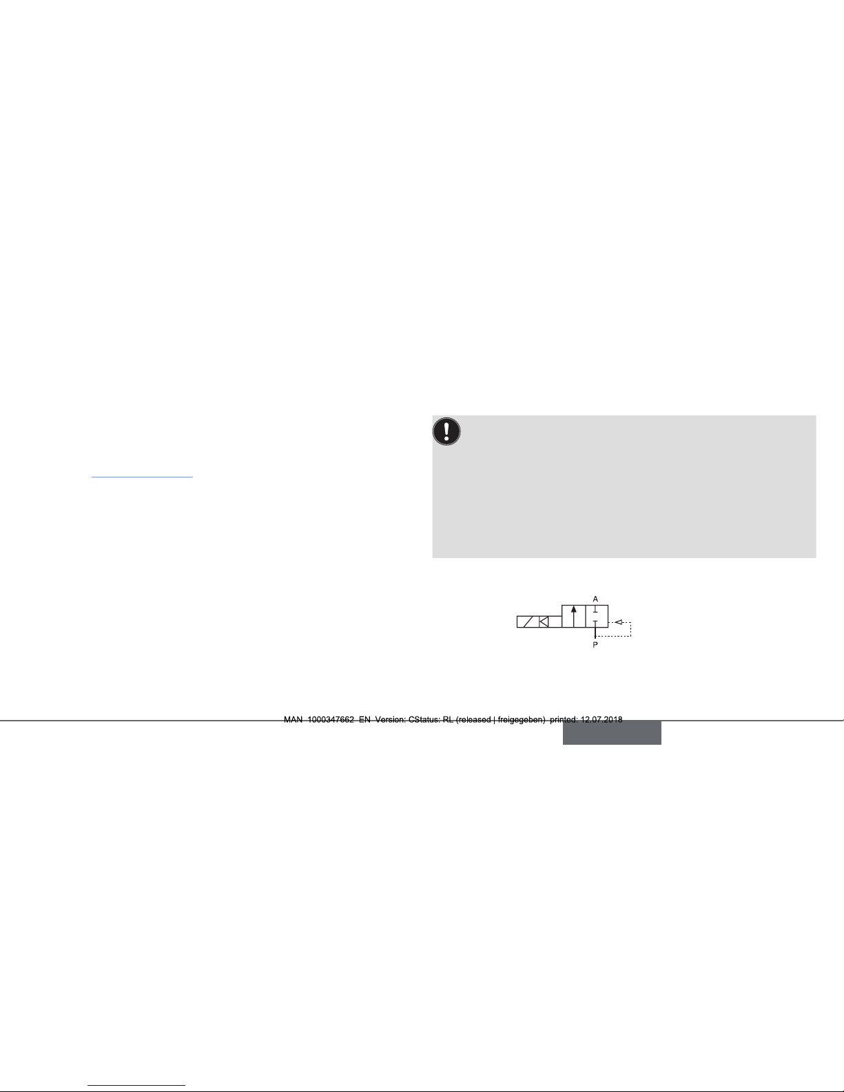
Circuit function 2/2-way valve:
A (NC)
Protection class: IP65 in accordance with DIN EN 60529 / IEC
60529 with cable plug, e.g. Bürkert Type 2518
english
Page 6

6
4.2 Conformity
The device conforms with the EU Directives according to the EU
Declaration of Conformity (if applicable).
4.3 Standards
The applied standards, which verify conformity with the EU Directives,
can be found on the EU-Type Examination Certicate and / or the EU
Declaration of Conformity (if applicable).
4.4 Application conditions
Ambient temperature: max. +45°C
max. +40 °C for ATEX/IECEx
Permitted medium temperature depending on coil material and seal
material:
Seal material Medium temperature
PTFE/Graphit -40 °C…+150 °C
EPDM/Graphit -40 °C…+135 °C
PTFE/FKM -10 °C…+120 °C
ATEX/IE CEx max. 90°C
Also observe for valves with UL/UR approval:
Medium Seal material Medium
temperature
Ambient
temperature
Air,
Inertgas
PTFE/Graphit -40 °C ... +120 °C -40 °C ... +55 °C
PTFE/FKM -10 °C ... +120 °C -10 °C ... +55 °C
Water
PTFE/Graphit 0 °C ... +100 °C 0 °C ... +55 °C
PTFE/FKM 0 °C ... +100 °C 0 °C ... +55 °C
Steam
(var. Code
NA07)
PTFE/Graphit 0 °C ... +150 °C 0 °C ... +45 °C
PTFE/FKM
0 °C ... +120 °C 0 °C ... +55 °C
Oil
PTFE/Graphit 0 °C ... +150 °C 0 °C ... +45 °C
PTFE/FKM -10 °C ... +120 °C -10 °C ... +55 °C
Operating duration: Unless otherwise stated on the type label,
the solenoid valve is suitable for continuous
operation.
Exception: Devices with kick-and-drop
electronics: Maximum duty cycle 50% and
maximum 6 switching cycles per minute.
english
Page 7

7
Important information for functional reliability during continuous
operation: If standstill for a long period at least 1-2 activations
per day are recommended.
Service life: High switching frequency and high pressures
reduce the service life
Permitted media depending on seal material:
Seal material Permitted media
PTFE/Graphit Vacuum, neutral gases and liquid media (e.g.
compressed air, water, hydraulic oil),
hot water and steam
PTFE/FKM
PTFE/EPDM Cold and warm water, oil and grease-free
media
NOTE!
If liquid media is used with high dierential pressures, water
hammer can occur.
4.5 Type label
Typ e
Circuit function
Nominal diameter
Seal material
Body material
Order number
Manufacture code
Voltage, Frequency, Power
consumption
Connection thread, Operating
pressure
6407 A 13,0 EG MS
Made in Germany
00320856
W12MN
230 V 50 Hz 16W
G1/2 P
N 0 - 10 bar
english
Page 8

8
5 INSTALLATION
DANGER!
Risk of injury from high pressure and discharge of medium.
▶ Before loosening the lines and valves, turn o the pressure and
vent the lines.
Risk of electric shock.
▶ Before reaching into the device, switch o the power supply and
secure to prevent reactivation.
▶ Observe applicable accident prevention and safety regulations
for electrical equipment.
WARNING!
Risk of injury from improper installation.
▶ Installation may be carried out by authorized technicians only
and with the appropriate tools.
▶ Secure system from unintentional activation.
▶ Following assembly, ensure a controlled restart.
5.1 Before installation
Installation position: any, actuator preferably upwards.
→ Check pipelines for dirt and clean.
→ Install a dirt lter before the valve inlet (≤ 500μm).
5.2 Installation
NOTE!
Caution risk of breakage.
• Do not use the coil as a lever arm.
→ Hold the device using a suitable tool on the body and screw into
the pipeline.
Valve body must not be installed under tension.
Sealing material must not get into the device.
→ Observe direction of ow:
The arrow on the body indicates the direction of ow.
english
Page 9

9
5.3 Electrical connection of the cable plug
WARNING!
Risk of injury due to electrical shock.
▶ Before reaching into the system, switch o the power supply
and secure to prevent reactivation.
▶ Observe applicable accident prevention and safety regulations
for electrical equipment.
If the protective conductor is not connected, there is a risk of
electric shock.
▶ Always connect protective conductor and check electrical conti-
nuity between coil and body.
→ Tighten cable plug (authorized cable plug see data sheet),
observing maximal torque 1 Nm.
→ Check that seal is tted correctly.
→ Connect protective conductor and check electrical continuity
between coil and body.
Authorized cable plug
e.g. Type 2518 or other suitable
cable plug in accordance with
DIN EN 175301-803, Form A
Seal
max. 1 Nm
english
Page 10

10
6 MAINTENANCE, TROUBLESHOOTING
DANGER!
Risk of injury from high pressure and discharge of medium.
▶ Before loosening the lines and valves, turn o the pressure and
vent the lines.
WARNING!
Risk of injury from improper maintenance.
▶ Maintenance may be carried out by authorized technicians only
and with the appropriate tools.
▶ Secure system from unintentional activation.
▶ Following maintenance, ensure a controlled restart.
6.1 Installation of the coil
WARNING!
Risk of injury due to electrical shock.
▶ Before reaching into the system, switch o the power supply and
secure to prevent reactivation.
If the protective conductor contact between the coil and body is
missing or if coil incorrectly installed, there is danger of electrical shock.
▶ Check protective conductor contact after installing the coil.
▶ During installation ensure that the coil is situated rmly on the body
cover so that the protective conductor connection of the coil is
connected to the valve body.
WARNING!
Escaping medium.
When a sticking nut is loosened, medium may escape.
▶ Do not tighten sticking nut any further.
Overheating, risk of re.
If the protective conductor contact between the coil and body is
missing, there is danger of electrical shock.
▶ Check protective conductor contact after installing the coil.
→ Connect coil body to the core guide pipe.
→ Screw on coil with nut. Observe the tightening torques in the
following table.
→ Check protective conductor.
english
Page 11

11
NOTE!
Device will be damaged if the wrong tools are used.
If other tools are used (e.g. pliers), the device may be damaged.
▶ Always use a wrench to tighten nut.
Observe tightening
torque for fastening nut
(see table)
Type DN Tightening torques [Nm] Fastening the coil
6407 13...32 15 Nut
6407 50 19 Nut
6.2 Malfunctions
If malfunctions occur, check whether:
• the device has been installed according to the instructions,
• the electrical and uid connections are correct,
• the device is not damaged,
• all screws have been tightened,
• the voltage and pressure have been switched on,
• the pipelines are clean,
• the power supply is adequately high.
Possible cause if the valve does not switch:
• Short circuit or coil interrupted.
• Inadequate power supply.
• Core or core area dirty.
• Medium pressure outside the permitted pressure range.
Possible cause if the valve does not close:
• Internal space of the valve is dirty.
english
Page 12

12
7 SPARE PARTS
CAUTION!
Risk of injury and damage by the use of incorrect parts.
Incorrect accessories and unsuitable spare parts may cause injuries
and damage the device and the surrounding area.
▶ Use only original accessories and original spare parts from
Bürkert.
7.1 Ordering spare parts
The following spare part are available for the Type 6407:
• Coil set (Pos. 1)
• Wearing parts set tting (Pos. 3)
Order the spare parts sets quoting the position and the order number
of the device.
7.2 Tightening torques
Type DN Cover screws
[Nm]
Plug with pipe
[Nm]
6407 13 3.0…4.0 49.0…51.0
6407 20 6.0…7.0 49.0…51.0
6407 25.0
32.0
8.0…10.0 49.0…51.0
6407 50.0 13.0…17.0 110.0…115.0
english
Page 13

13
7.3 Overview of spare parts
1
3
2
DN13...DN32
1
3
DN50
8 TRANSPORT, STORAGE, DISPOSAL
NOTE!
Transport damages when inadequately protected devices.
• During transportation protect the device against wet and dirt in
shock-resistant packaging.
• Avoid exceeding or dropping below the permitted storage
temperature.
Incorrect storage may damage the device.
• Store the device in a dry and dust-free location.
• Storage temperature: -40 … +80 °C.
Damage to the environment caused by device components
contaminated with media.
• Dispose of the device and packaging in an environmentally
friendly manner.
• Observe applicable regulations on disposal and the
environment.
english
Page 14

www.burkert.com
International address
www.burkert.com
Manuals and data sheets on the Internet : www.burkert.com
Bedienungsanleitungen und Datenblätter im Internet: www.buerkert.de
Manuels d'utilisation et fiches techniques sur Internet: www.buerkert.fr
© Bürker t Werke GmbH & Co. KG, 2017 - 2018
Operating Instructions 1807/02_EU-ML_00810672 / Original DE
Bürkert Fluid Control Systems
Sales Center
Christian-Bürkert-Str. 13-17
D-74653 Ingelfingen
Tel. + 49 (0) 7940 - 10-91 111
Fax + 49 (0) 7940 - 10-91 448
E-mail: info@burkert.com
 Loading...