

Page 1
www.burkert.com
We reserve the right to make
technical changes without notice.
Technische Änderungen
vorbehalten.
Sous réserve de modifications
techniques.
© 2011 Bürkert Werke GmbH
Operating Instructions 1105/00_EU-ml_00809549 / Original DE
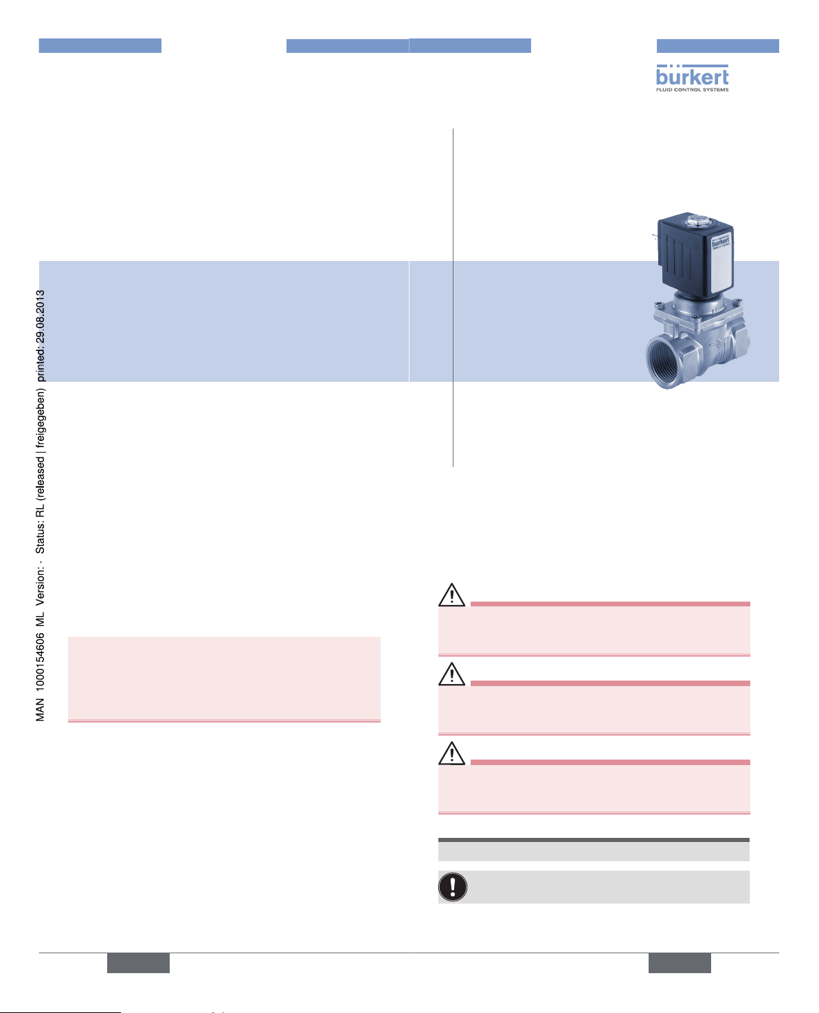
Type 6203 EV
2/2-way solenoid valve
2/2-Wege Magnetventil
Électrovanne 2/2 voies
Operating Instructions
Bedienungsanleitung
Manuel d‘utilisation
2
1. OPERATING INSTRUCTIONS
The operating instructions describe the entire life cycle of the
device. Keep these instructions in a location which is easily
accessible to every user and make these instructions available
to every new owner of the device.
The operating instructions contain important safety
information!
Failure to observe these instructions may result in hazardous
situations.
• The operating instructions must be read and understood.
english
3
2. SYMBOLS
In these instructions, the following symbols are used.
DANGER!
Warns of an immediate danger!
• Failure to observe the warning may result in a fatal or
serious injury.
WARNING!
Warns of a potentially dangerous situation!
• Failure to observe the warning may result in a serious or
fatal injury.
CAUTION!
Warns of a possible danger!
• Failure to observe the warning may result in medium or
minor injury.
NOTE!
Warns of damage to property!
Important tips and recommendations.
→ designates a procedure which you must carry out.
english
Page 2
4
3. AUTHORISED USE
Non-authorized use of the solenoid valve Type 6203
EV may be a hazard to people, nearby equipment
and the environment.
• The device is designed to control, shut off and meter
neutral media up to a viscosity of 21 mm
2
/s.
• Provided the device socket is connected and installed
correctly, e.g. Bürkert Type 2508, the device satisfies
protection class IP65 in accordance with DIN EN 60529
/ IEC 60529.
• Use according to the authorized data, operating and
service conditions specified in the contract documents
and operating instructions. These are described in the
chapter on “Technical data”.
• Correct transportation, correct storage and installation
and careful use and maintenance are essential for reliable
and faultless operation.
• Use the device only as intended.
3.1. Restrictions
If exporting the system/device, observe any existing
restrictions.
english
5
3.2. Predictable misuse
• The device may only be used in the explosion-protected
area if an appropriate additional identification is attached
to the type label.
• Do not put any loads on the housing (e.g. by placing objects
on it or standing on it).
• Do not make any external modifications to the device
housings. Do not paint the housing parts or screws.
english
6
4. BASIC SAFETY
INSTRUCTIONS
These safety instructions do not make allowance for any
• contingencies and events which may arise during the
installation, operation and maintenance of the devices.
• local safety regulations – the operator is responsible for
observing these regulations, also with reference to the
installation personnel.
Danger – high pressure!
• Before loosening the lines and valves, turn off the pressure and vent the lines.
Risk of electric shock!
• Before reaching into the system, switch off the power
supply and secure to prevent reactivation.
• Observe applicable accident prevention and safety
regulations for electrical equipment!
Risk of burns/risk of fire if used for a prolonged switchon time through hot device surface!
• Keep the device away from highly flammable substances
and media and do not touch with bare hands.
english
7
Risk of injury due to malfunction of valves with alternating current (AC).
Sticking core causes coil to overheat, resulting in a
malfunction.
• Monitor process to ensure function is in perfect working order!
Risk of short-circuit/escape of media through leaking
screw joints.
• Ensure seals are seated correctly!
• Carefully screw together coil and device socket or valve
and connection plate!
General Hazardous Situations.
To prevent injuries:
• Ensure that the system cannot be activated unintentionally.
• Installation and maintenance work may only be carried
out by authorized technicians with the appropriate tools.
• After an interruption in the power supply, ensure that the
process is restarted in a defined or controlled manner.
english
Type 6203 EV
Page 3
8
• The device may be installed and operated only when in
a perfect condition and in consideration of the operating
instructions.
• The general rules of technology must be observed for
application planning and operation of the device.
Failure to observe this operating manual and its
operating instructions as well as unauthorized tampering with the device release us from any liability
and also invalidate the warranty covering the device
and accessories!
english
9
5. GENERAL INFORMATION
5.1. Contact address
Germany
Bürkert Fluid Control Systems
Sales Center
Christian-Bürkert-Str. 13-17
D-74653 Ingelfingen
Tel. + 49 (0) 7940 - 10 91 111
Fax + 49 (0) 7940 - 10 91 448
E-mail: info@de.buerkert.com
International
Contact addresses can be found on the final pages of the
printed operating instructions.
And also on the internet at: www.burkert.com
5.2. Warranty
The warranty is only valid if the device is used as intended in
accordance with the specified application conditions.
5.3. Information on the Internet
The operating instructions and data sheets for Type 6203 EV
can be found on the Internet at: www.burkert.com
english
10
6. TECHNICAL DATA
The following values are indicated on the type label:
• Voltage (Tolerance ±10 %) / Current type
• Coil power consumption
(active power in W - at operating temperature)
• Pressure range
• Housing material
Brass (MS) or stainless steel (VA)
• Seal material
FKM, EPDM, NBR
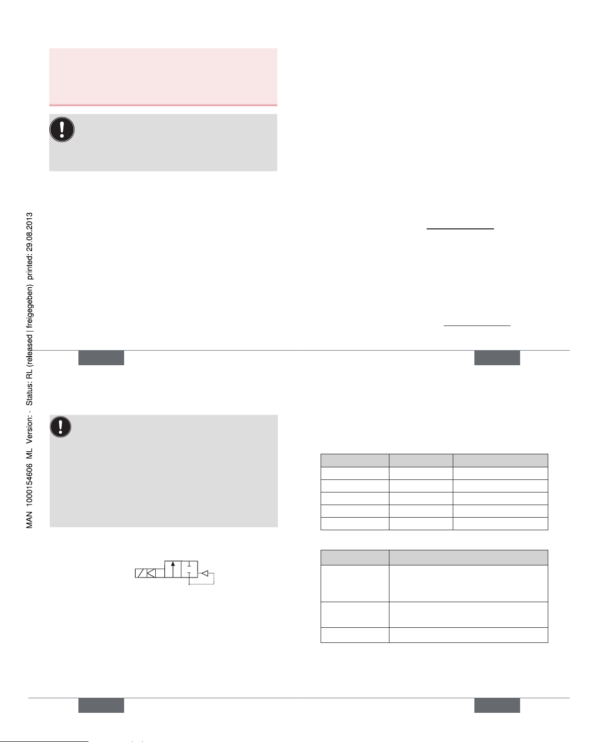
Operating principle 2/2-way valve:
A (NC)
A
P
Protection class: IP65 in accordance with DIN EN
60529 / IEC 60529 with correctly
connected and installed device
socket, e.g. Type 2508
english
11
6.1. Application conditions
Ambient temperature: max. +55 °C
Permitted medium temperature depending on coil and seal
material:
Coil housing Seal material Medium temperature
Polyamide FKM 0 ... +90 °C
Epoxy (NA38) FKM 0 ... +120 °C
Epoxy (NA38) EPDM -30 ... +100 °C
Polyamide EPDM -30 ... +90 °C
Polyamide NBR -10 ... +80 °C
Permitted media depending on seal material:
Seal material Permitted media
1)
FKM Per-solutions, hot oils without addi-
tives, diesel and heating oil without
additives, detergent solution
EPDM Oil and grease-free liquids, cold and
hot water
NBR Cold and warm water
1)
Gaseous media at low differential pressures (e.g. compressed
air and vacuum) can also be actuated in consideration (or due to
restriction) of a lower tightness. We recommend prior clarification
with our sales office regarding the possible application.
english
Type 6203 EV
Page 4

12
Operating duration
Unless otherwise indicated on the type label, the solenoid
system is suitable for continuous operation.
Important information for functional reliability during
continuous operation!
For long switch-on or switch-off times a minimum
actuation of 1-2 switching operations per day is
recommended.
Service life
High switching frequency and high pressures reduce the
service life.
english
13
6.2. Type label
6203 A 10 EPDM MS
Made in Germany
00229009
W14 LU
230V 50Hz 8W
G3/8 P
N0 - 10bar
Type
Operating principle
Orifice
Seal material
Housing material
Identification number
Manufacturer code
Voltage, Frequency, Power
consumption
Connection thread, Nominal pressure
Fig. 1: Location and description of the type label
english
14
7. INSTALLATION
7.1. Safety instructions
DANGER!
Risk of injury from high pressure in the equipment!
• Before loosening the lines and valves, turn off the
pressure and vent the lines.
Risk of injury due to electrical shock!
• Before reaching into the system , switch off the power
supply and secure to prevent reactivation!
• Observe applicable accident prevention and safety
regulations for electrical equipment!
WARNING!
Risk of injury from improper installation!
• Installation may only be carried out by authorized technicians with the appropriate tools!
Risk of injury from unintentional activation of the
system and an uncontrolled restart!
• Secure system from unintentional activation.
• Following assembly, ensure a controlled restart.
english
15
7.2. Before Installation
Installation position:
Installation can be in any position.
Preferably: Drive at the top.
→ Prior to installation check pipelines for dirt and if
required, clean.
Dirt filter: To ensure that the solenoid valve functions
reliably, a dirt filter (≤ 500 μm) must be installed in front of
the valve inlet.
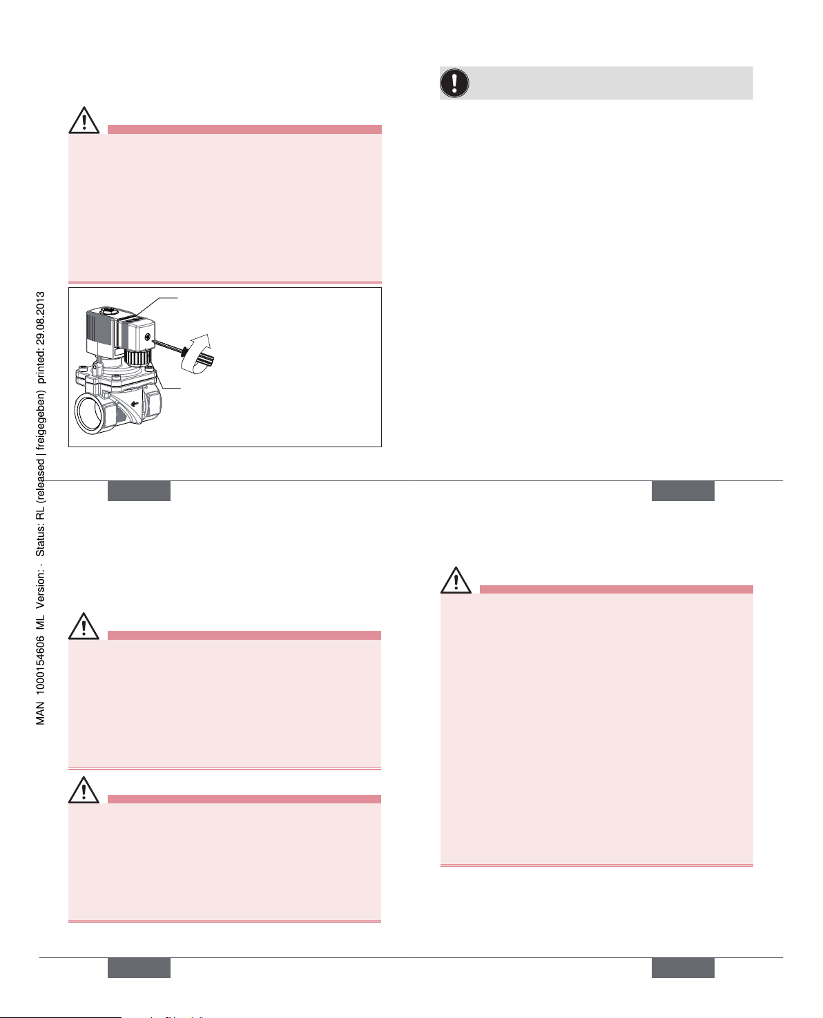
7.3. Installation
→ Hold the device with a suitable tool (open-end wrench)
on the housing and screw into the pipeline.
NOTE!
Caution risk of breakage!
• Do not use the coil as a lifting arm.
→ Observe direction of flow:
The arrow on the housing indicates the direction of
flow.
english
Type 6203 EV
Page 5
16
7.4. Electrical connection of the
device socket
WARNING!
Risk of injury due to electrical shock!
• Before reaching into the system, switch off the electrical
power supply and secure to prevent reactivation!
• Observe applicable accident prevention and safety
regulations for electrical equipment!
If the protective conductor contact between the coil and
housing is missing, there is danger of electrical shock!
• Always connect protective conductor.
• Check electrical continuity between coil and housing.
Authorized device socket e.g. Type
2508 in accordance with DIN ISO
175301-803 Form A
Seal
max. 1 Nm
Fig. 2: Electrical connection of the device socket
english
17
Note the voltage and current type as specified on
the type label.
→ Tighten device socket (for permitted types see data
sheet), observing max. torque of 1 Nm.
→ Check that seal is fitted correctly.
→ Connect protective conductor and check electrical con-
tinuity between coil and housing.
english
18
8. MAINTENANCE,
TROUBLESHOOTING
8.1. Safety instructions
DANGER!
Risk of injury from high pressure in the equipment!
• Before loosening the lines and valves, turn off the pressure and vent the lines.
Risk of injury due to electrical shock!
• Before reaching into the system , switch off the power
supply and secure to prevent reactivation!
• Observe applicable accident prevention and safety
regulations for electrical equipment!
WARNING!
Risk of injury from improper maintenance!
• Maintenance may only be carried out by authorized
technicians with the appropriate tools!
Risk of injury from unintentional activation of the
system and an uncontrolled restart!
• Secure system from unintentional activation.
• Following maintenance, ensure a controlled restart.
english
19
8.2. Installation of coil
WARNING!
Escaping medium!
When a sticking nut is loosened, medium may escape.
• Do not tighten sticking nut any further.
Electric shock!
If the protective conductor contact between the coil and
housing is missing, there is danger of electrical shock!
• Check protective conductor contact after installing the
coil.
Overheating, risk of fire!
Connection of the coil without pre-assembled valve will
result in overheating and destroy the coil.
• Connect the coil with pre-assembled valve only.
Danger due to electrical shock if coil incorrectly installed!
• During installation ensure that the coil is seated firmly
on the step of the core guide tube so that the protective
conductor connection of the coil has a connection to
the valve housing.
Procedure:
→ Connect coil housing to the core guide pipe.
→ Screw on coil with nut. Observe torque.
→ Check protective conductor.
english
Type 6203 EV
Page 6
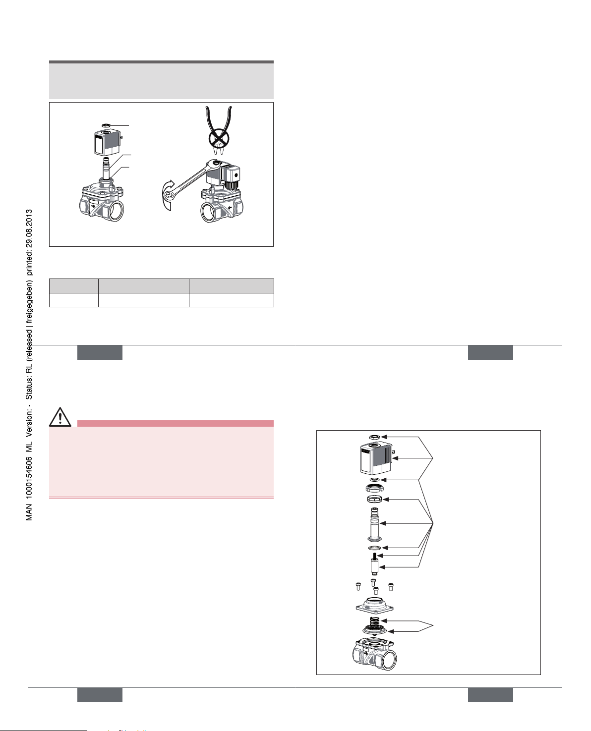
20
NOTE!
Device will be damaged if the wrong tools are used!
Always use a wrench to tighten nut. If other tools are used
(e.g. pliers), the device may be damaged.
Observe torque!
(see table below)
Nut
O-ring
Core guide tube
Fig. 3: Coil installation
Torque for fastening nut:
Coil type Coil width Torque [Nm]
AC10 32 mm or 40 mm 5 Nm
english
21
8.3. Malfunctions
If malfunctions occur, check whether:
→ the device has been installed according to the
instructions,
→ the electrical and fluid connections are correct,
→ the device is not damaged,
→ all screws have been tightened,
→ the voltage and pressure have been switched on,
→ the pipelines are clean.
Valve does not switch
Possible cause:
• Short circuit or coil interrupted,
• Core or core area dirty.
• Medium pressure outside the permitted pressure range.
Valve does not close
Possible cause:
• Internal space of the valve is dirty.
• Small control bore in the diaphragm blocked.
english
22
9. SPARE PARTS
CAUTION!
Risk of injury and/or damage by the use of incorrect
parts!
Incorrect accessories and unsuitable spare parts may cause
injuries and damage the device and the surrounding area.
• Use original accessories and original spare parts from
Bürkert only.
9.1. Ordering spare parts
Replacement part sets
When ordering replacement part sets, quote the sets SET 1,
SET 3 or SET 7 and the identification number of the device.
• See replacement part sets 9.2. and 9.3
• The identification number of the device can be found on
the type label. See also chapter “6.2. Type label”.
english
23
9.2. Overview of replacement part
sets Type 6203 EV, DN 10,
DN 13
Coil set
SET 1
Wearing-parts
set SET 3
Plunger tube set
SET 7
Fig. 4: Replacement part sets Type 6203 EV
english
Type 6203 EV
Page 7
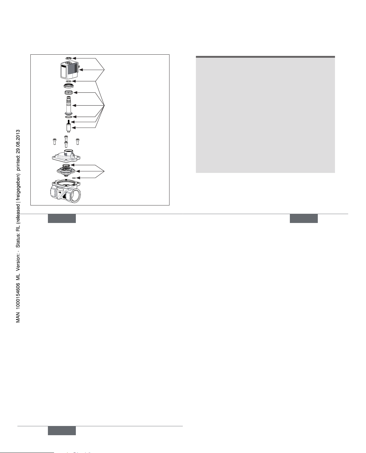
24
9.3. Overview of replacement part
sets Type 6203 EV, DN 20,
DN 25 and DN 40
Coil set
SET 1
Plunger tube set
SET 7
Wearing-parts
set SET 3
Fig. 5: Replacement part sets Type 6203 EV
english
25
10. PACKAGING, TRANSPORT,
STORAGE, DISPOSAL
NOTE!
Transport damages!
Inadequately protected equipment may be damaged
during transport.
• During transportation protect the device against wet
and dirt in shock-resistant packaging.
• Avoid exceeding or dropping below the allowable
storage temperature.
Incorrect storage may damage the device.
• Store the device in a dry and dust-free location!
• Storage temperature. -40 … +80 °C.
Damage to the environment caused by device components contaminated with media.
• Observe applicable regulations on disposal and the
environment.
• Observe national waste disposal regulations.
english
26
english
Type 6203 EV
Page 8

www.burkert.com
We reserve the right to make
technical changes without notice.
Technische Änderungen
vorbehalten.
Sous réserve de modifications
techniques.
© 2011 Bürkert Werke GmbH
Operating Instructions 1105/00_EU-ml_00809549 / Original DE
Typ 6203 EV
2/2-Wege Magnetventil
Bedienungsanleitung
Deutsch
28
1. DIE BEDIENUNGSANLEITUNG
Die Bedienungsanleitung beschreibt den gesamten Lebenszyklus des Gerätes. Bewahren Sie diese Anleitung so auf,
dass sie für jeden Benutzer gut zugänglich ist und jedem
neuen Eigentümer des Gerätes wieder zur Verfügung steht.
Die Bedienungsanleitung enthält wichtige Informationen zur Sicherheit!
Das Nichtbeachten dieser Hinweise kann zu gefährlichen
Situationen führen.
• Die Bedienungsanleitung muss gelesen und verstanden
werden.
deutsch
29
2. DARSTELLUNGSMITTEL
In dieser Anleitung werden folgende Darstellungsmittel
verwendet.
GEFAHR!
Warnt vor einer unmittelbaren Gefahr!
• Bei Nichtbeachtung sind Tod oder schwere Verletzungen die Folge.
WARNUNG!
Warnt vor einer möglicherweise gefährlichen Situation!
• Bei Nichtbeachtung können schwere Verletzungen oder
Tod die Folge sein.
VORSICHT!
Warnt vor einer möglichen Gefährdung!
• Nichtbeachtung kann mittelschwere oder leichte Verletzungen zur Folge haben.
HINWEIS!
Warnt vor Sachschäden!
Wichtige Tipps und Empfehlungen.
→ markiert einen Arbeitsschritt den Sie ausführen müssen.
deutsch
Page 9

30
3. BESTIMMUNGSGEMÄSSE
VERWENDUNG
Bei nicht bestimmungsgemäßem Einsatz des Typs
6203 EV können Gefahren für Personen, Anlagen in
der Umgebung und die Umwelt entstehen.
• Das Gerät ist zum Steuern, Absperren und Dosieren von
neutralen Medien bis zu einer Viskosität von 21 mm
2
/s
konzipiert.
• Mit einer sachgemäß angeschlossenen und montierten
Gerätesteckdose, z. B. Bürkert Typ 2508 erfüllt das Gerät
die Schutzart IP65 nach DIN EN 60529 / IEC 60529.
• Für den Einsatz die in den Vertragsdokumenten und
der Bedienungsanleitung spezifizierten zulässigen
Daten, Betriebs- und Einsatzbedingungen beachten.
Diese sind im Kapitel „Technische Daten“ beschrieben.
• Voraussetzungen für den sicheren und einwandfreien
Betrieb sind sachgemäßer Transport, sachgemäße
Lagerung und Installation sowie sorgfältige Bedienung
und Instandhaltung.
• Das Gerät nur bestimmungsgemäß einsetzen.
3.1. Beschränkungen
Bei der Ausfuhr des Systems/Gerätes gegebenenfalls bestehende Beschränkungen beachten.
deutsch
31
3.2. Vorhersehbarer Fehlgebrauch
• Im explosionsgeschützten Bereich darf das Gerät nur
eingesetzt werden, wenn auf dem Typenschild eine entsprechende zusätzliche Kennzeichnung angebracht ist.
• Das Gehäuse nicht mechanisch belasten (z. B. durch
Ablage von Gegenständen oder als Trittstufe).
• Keine äußerlichen Veränderungen an den Gerätegehäusen
vornehmen. Gehäuseteile und Schrauben nicht lackieren.
deutsch
32
4. GRUNDLEGENDE
SICHERHEITSHINWEISE
Diese Sicherheitshinweise berücksichtigen keine
• Zufälligkeiten und Ereignisse, die bei Montage, Betrieb
und Wartung der Geräte auftreten können.
• ortsbezogenen Sicherheitsbestimmungen, für deren
Einhaltung, auch in Bezug auf das Montagepersonal, der
Betreiber verantwortlich ist.
Gefahr durch hohen Druck!
• Vor dem Lösen von Leitungen oder Ventilen den Druck
abschalten und Leitungen entlasten.
Gefahr durch elektrische Spannung!
• Vor Eingriffen in das Gerät oder die Anlage, Spannung
abschalten und vor Wiedereinschalten sichern!
• Die geltenden Unfallverhütungs- und Sicherheitsbestimmungen für elektrische Geräte beachten!
Verbrennungsgefahr/Brandgefahr bei längerer Einschaltzeit durch heiße Geräteoberfläche!
• Das Gerät von leicht brennbaren Stoffen und Medien
fernhalten und nicht mit bloßen Händen berühren.
deutsch
33
Verletzung durch Funktionsausfall bei Ventilen mit
Wechselspannung (AC).
Festsitzender Kern bewirkt Spulenüberhitzung, die zu
Funktionsausfall führt.
• Arbeitsprozess auf einwandfreie Funktion überwachen.
Kurzschlussgefahr / Austritt von Medium durch
undichte Verschraubungen.
• Auf einwandfreien Sitz der Dichtungen achten.
• Ventil und Anschlussleitungen sorgfältig verschrauben.
Allgemeine Gefahrensituationen.
Zum Schutz vor Verletzungen ist zu beachten:
• Dass die Anlage nicht unbeabsichtigt betätigt werden
kann.
• Installations- und Instandhaltungsarbeiten dürfen nur von
autorisiertem Fachpersonal mit geeignetem Werkzeug
ausgeführt werden.
• Nach einer Unterbrechung der elektrischen Versorgung
ist ein definierter oder kontrollierter Wiederanlauf des
Prozesses zu gewährleisten.
deutsch
Typ 6203 EV
Page 10

34
• Das Gerät darf nur in einwandfreiem Zustand und unter
Beachtung der Bedienungsanleitung betrieben werden.
• Für die Einsatzplanung und den Betrieb des Gerätes
müssen die allgemeinen Regeln der Technik eingehalten
werden.
Bei Nichtbeachtung dieser Bedienungsanleitung
und ihrer Hinweise sowie bei unzulässigen Eingriffen
in das Gerät entfällt jegliche Haftung unsererseits,
ebenso erlischt die Gewährleistung auf Geräte und
Zubehörteile!
deutsch
35
5. ALLGEMEINE HINWEISE
5.1. Kontaktadresse
Deutschland
Bürkert Fluid Control Systems
Sales Center
Christian-Bürkert-Str. 13-17
D-74653 Ingelfingen
Tel. + 49 (0) 7940 - 10 91 111
Fax + 49 (0) 7940 - 10 91 448
E-mail: info@de.buerkert.com
International
Die Kontaktadressen finden Sie auf den letzten Seiten der
gedruckten Bedienungsanleitung.
Außerdem im Internet unter: www.burkert.com
5.2. Gewährleistung
Voraussetzung für die Gewährleistung ist der bestimmungsgemäße Gebrauch des Typs 6203 EV unter Beachtung der
spezifizierten Einsatzbedingungen.
5.3. Informationen im Internet
Bedienungsanleitungen und Datenblätter zum Typ 6203 EV
finden Sie im Internet unter: www.buerkert.de
deutsch
36
6. TECHNISCHE DATEN
Folgende Werte sind auf dem Typenschild
angegeben:
• Spannung (Toleranz ±10 %) / Stromart
• Spulenleistung
(Wirkleistung in W - betriebswarm)
• Druckbereich
• Gehäusewerkstoff
Messing (MS) oder Edelstahl (VA)
• Dichtwerkstoff
FKM, EPDM, NBR
Wirkungsweise 2/2-Wege Ventil:
A (NC)
A
P
Schutzart: IP65 nach DIN EN 60529 / IEC 60529 mit
sachgemäß angeschlossener und montierter
Gerätesteckdose, z. B. Bürkert Typ 2508
deutsch
37
6.1. Einsatzbedingungen
Umgebungstemperatur: max. +55 °C
Zulässige Mediumstemperatur in Abhängigkeit von Spule
und Dichtwerkstoff:
Spulengehäuse Dichtwerkstoff Mediumstemperatur
Polyamid FKM 0 ... +90 °C
Epoxid (NA38) FKM 0 ... +120 °C
Epoxid (NA38) EPDM -30 ... +100 °C
Polyamid EPDM -30 ... +90 °C
Polyamid NBR -10 ... +80 °C
Zulässige Medien in Abhängigkeit vom Dichtwerkstoff:
Dichtwerkstoff Zulässige Medien
1)
FKM Per-Lösungen, heiße Öle ohne
Additive, Diesel und Heizöl ohne
Additive, Waschlauge
EPDM Öl- und fettfreie Flüssigkeiten, Kalt-
und Heißwasser
NBR Kalt- und Warmwasser
1)
Gasförmige Medien bei kleinen Differenzdrücken (z. B. Druckluft
und Vakuum) können unter Berücksichtigung (oder Einschränkung) einer geringeren Dichtheit ebenfalls geschalten
werden. Wir empfehlen eine vorherige Klärung der Einsatzmöglichkeit mit unserer Vertriebsniederlassung.
deutsch
Typ 6203 EV
Page 11

38
Betriebsdauer
Wenn auf dem Typenschild nicht anders angegeben, ist das
Magnetsystem für Dauerbetrieb geeignet.
Wichtiger Hinweis für die Funktionssicherheit bei
Dauerbetrieb!
Bei langen Ein- oder Ausschaltzeiten wird eine
Mindestbetätigung von 1-2 Schaltungen pro Tag
empfohlen.
Lebensdauer
Hohe Schaltfrequenz und hohe Drücke verringern die
Lebensdauer.
deutsch
39
6.2. Typenschild
6203 A 10 EPDM MS
Made in Germany
00229009
W14 LU
230V 50Hz 8W
G3/8 P
N0 - 10bar
Typ
Wirkungsweise
Nennweite
Dichtwerkstoff
Gehäusewerkstoff
Identnummer
Hersteller-Code
Spannung, Frequenz, Leistung
Anschlussgewinde, Nenndruck
Bild 1: Lage und Beschreibung des Typenschildes
deutsch
40
7. MONTAGE
7.1. Sicherheitshinweise
GEFAHR!
Verletzungsgefahr durch hohen Druck in der Anlage!
• Vor dem Lösen von Leitungen oder Ventilen den Druck
abschalten und Leitungen entlüften.
Verletzungsgefahr durch Stromschlag!
• Vor Eingriffen in das Gerät oder die Anlage, Spannung
abschalten und vor Wiedereinschalten sichern!
• Die geltenden Unfallverhütungs- und Sicherheitsbestimmungen für elektrische Geräte beachten!
WARNUNG!
Verletzungsgefahr bei unsachgemäßer Montage!
• Die Montage darf nur autorisiertes Fachpersonal mit
geeignetem Werkzeug durchführen!
Verletzungsgefahr durch ungewolltes Einschalten der
Anlage und unkontrollierten Wiederanlauf!
• Anlage vor unbeabsichtigtem Betätigen sichern.
• Nach der Montage einen kontrollierten Wiederanlauf
gewährleisten.
deutsch
41
7.2. Vor dem Einbau
Einbaulage:
Die Einbaulage ist beliebig.
Vorzugsweise: Antrieb oben.
→ Rohrleitungen vor dem Einbau auf Verschmutzungen
überprüfen und gegebenenfalls reinigen.
Schmutzfilter: Für die sichere Funktion des Magnetventils
muss vor dem Ventileingang ein Schmutzfilter (≤ 500 µm)
eingebaut werden.
7.3. Einbau
→ Das Gerät mit geeignetem Werkzeug (Gabelschlüssel)
am Gehäuse festhalten und in die Rohrleitung
einschrauben.
HINWEIS!
Vorsicht Bruchgefahr!
• Die Spule darf nicht als Hebelarm benutzt werden.
→ Durchflussrichtung beachten:
Der Pfeil auf dem Gehäuse kennzeichnet die
Durchflussrichtung.
deutsch
Typ 6203 EV
Page 12

42
7.4. Elektrischer Anschluss der
Gerätesteckdose
WARNUNG!
Verletzungsgefahr durch Stromschlag!
• Vor Eingriffen in das Gerät oder Anlage die Spannung
abschalten und vor Wiedereinschalten sichern!
• Die geltenden Unfallverhütungs- und Sicherheitsbestimmungen für elektrische Geräte beachten!
Bei nicht angeschlossenem Schutzleiter besteht die Gefahr
des Stromschlags!
• Schutzleiter immer anschließen.
• Elektrischer Durchgang zwischen Spule und Gehäuse
prüfen.
Zugelassene Gerätesteckdose
z. B. Typ 2508 oder andere nach
DIN ISO 175301-803 Form A
Dichtung
max. 1 Nm
Bild 2: Elektrischer Anschluss der Gerätesteckdose
deutsch
43
Spannung und Stromart laut Typenschild beachten.
→ Gerätesteckdose (zugelassene Typen siehe Datenblatt)
festschrauben, dabei max. Drehmoment 1 Nm beachten.
→ Korrekten Sitz der Dichtung überprüfen.
→ Schutzleiter anschließen und elektrischer Durchgang
zwischen Spule und Gehäuse prüfen.
deutsch
44
8. WARTUNG,
FEHLERBEHEBUNG
8.1. Sicherheitshinweise
GEFAHR!
Verletzungsgefahr durch hohen Druck in der Anlage!
• Vor dem Lösen von Leitungen oder Ventilen den Druck
abschalten und Leitungen entlüften.
Verletzungsgefahr durch Stromschlag!
• Vor Eingriffen in das Gerät oder die Anlage, Spannung
abschalten und vor Wiedereinschalten sichern!
• Die geltenden Unfallverhütungs- und Sicherheitsbestimmungen für elektrische Geräte beachten!
WARNUNG!
Verletzungsgefahr bei unsachgemäßen
Wartungsarbeiten!
• Die Wartung darf nur autorisiertes Fachpersonal mit
geeignetem Werkzeug durchführen!
Verletzungsgefahr durch ungewolltes Einschalten
der Anlage und unkontrollierten Wiederanlauf!
• Anlage vor unbeabsichtigtem Betätigen sichern.
• Nach der Wartung einen kontrollierten Wiederanlauf
gewährleisten.
deutsch
45
8.2. Spulenmontage
WARNUNG!
Mediumsaustritt!
Beim Lösen festsitzender Mutter kann Medium austreten.
• Festsitzende Mutter nicht weiterdrehen.
Stromschlag!
Bei nicht angeschlossenem Schutzleiter besteht die
Gefahr des Stromschlags!
• Schutzleiterkontakt nach der Spulenmontage prüfen.
Überhitzung, Brandgefahr!
Der Anschluss der Spule ohne vormontiertes Ventil führt
zur Überhitzung und zerstört die Spule.
• Spule nur mit vormontiertem Ventil anschließen.
Gefahr durch Stromschlag bei falscher Montage der
Spule!
• Bei der Montage beachten, dass die Spule fest auf der
Stufe vom Kernführungsrohr aufsitzt damit der Schutzleiteranschluss der Spule Verbindung zum Ventilgehäuse hat.
Vorgehensweise:
→ Spulengehäuse auf Kernführungsrohr aufstecken.
→ Spule mittels Mutter verschrauben. Drehmoment
beachten.
→ Schutzleiter prüfen.
deutsch
Typ 6203 EV
Page 13

46
HINWEIS!
Geräteschaden durch falsches Werkzeug!
Mutter immer mit einem Gabelschlüssel festschrauben. Bei
der Verwendung anderer Werkzeuge (z. B. Zange) kann
das Gerät beschädigt werden.
Drehmoment beachten!
(siehe Tabelle unten)
Mutter
O-Ring
Kernführungsrohr
Bild 3: Spulenmontage
Drehmomente für Befestigungsmutter:
Spulentyp Spulenbreite Drehmoment [Nm]
AC10 32 mm bzw. 40 mm 5 Nm
deutsch
47
8.3. Störungen
Überprüfen Sie bei Störungen ob:
→ das Gerät vorschriftsmäßig installiert ist,
→ der elektrische und fluidische Anschluss ordnungsgemäß
ausgeführt ist,
→ das Gerät nicht beschädigt ist,
→ alle Schrauben fest angezogen sind,
→ Spannung und Druck anliegen,
→ die Rohrleitungen schmutzfrei sind.
Ventil schaltet nicht
Mögliche Ursache:
• Kurzschluss oder Spulenunterbrechung.
• Kern oder Kernraum verschmutzt.
• Mediumsdruck außerhalb des zulässigen Druckbereichs.
Ventil schließt nicht
Mögliche Ursache:
• Innenraum des Ventils verschmutzt.
• Kleine Steuerbohrung in der Membrane verstopft.
deutsch
48
9. ERSATZTEILE
VORSICHT!
Verletzungsgefahr, Sachschäden durch falsche Teile!
Falsches Zubehör und ungeeignete Ersatzteile können Verletzungen und Schäden am Gerät und dessen Umgebung
verursachen.
• Nur Originalzubehör sowie Originalersatzteile der Firma
Bürkert verwenden.
9.1. Ersatzteile bestellen
Ersatzteilsätze
Bestellen Sie Ersatzteilsätze unter Angabe der Sätze SET 1,
SET 3 oder SET 7 und der Identnummer des Gerätes.
• Ersatzteilsätze siehe Kapitel 9.2. und 9.3.
• Die Identnummer des Gerätes finden Sie auf dem Typenschild. Siehe auch Kapitel „6.2. Typenschild“.
deutsch
49
9.2. Übersicht Ersatzteilsätze Typ
6203 EV DN 10, DN 13
Spulensatz
SET 1
Verschleißteilsatz
SET 3
Stopfensatz
SET 7
Bild 4: Ersatzteilsätze Typ 6203 EV
deutsch
Typ 6203 EV
Page 14

50
9.3. Übersicht Ersatzteilsätze Typ
6203 EV, DN 20, DN 25 und
DN 40
Spulensatz
SET 1
Stopfensatz
SET 7
Verschleißteilsatz
SET 3
Bild 5: Ersatzteilsätze Typ 6203 EV
deutsch
51
10. VERPACKUNG, TRANSPORT,
LAGERUNG, ENTSORGUNG
HINWEIS!
Transportschäden!
Unzureichend geschützte Geräte können durch den
Transport beschädigt werden.
• Gerät vor Nässe und Schmutz geschützt in einer stoßfesten Verpackung transportieren.
• Eine Über- bzw. Unterschreitung der zulässigen Lagertemperatur vermeiden.
Falsche Lagerung kann Schäden am Gerät
verursachen.
• Gerät trocken und staubfrei lagern!
• Lagertemperatur. -40 … +80 °C.
Umweltschäden durch von Medien kontaminierte
Geräteteile.
• Gerät und Verpackung umweltgerecht entsorgen!
• Geltende Entsorgungsvorschriften und Umweltbestimmungen einhalten.
deutsch
52
deutsch
Typ 6203 EV
Page 15

www.burkert.com
We reserve the right to make
technical changes without notice.
Technische Änderungen
vorbehalten.
Sous réserve de modifications
techniques.
© 2011 Bürkert Werke GmbH
Operating Instructions 1105/00_EU-ml_00809549 / Original DE
Type 6203 EV
Électrovanne 2/2 voies
Manuel d‘utilisation
Français
54
1. LES INSTRUCTIONS DE
SERVICE
Les instructions de service décrivent le cycle de vie complet
de l‘appareil. Conservez ces instructions de sorte qu‘elles
soient accessibles à tout utilisateur et à disposition de tout
nouveau propriétaire.
Les instructions de service contiennent des informations importantes sur la sécurité !
Le non-respect de ces consignes peut entraîner des
situations dangereuses.
• Les instructions de service doivent être lues et comprises.
français
55
2. SYMBOLES
Les moyens de représentation suivants sont utilisés dans
les présentes instructions de service.
DANGER !
Met en garde contre un danger imminent !
• Le non-respect peut entraîner la mort ou de graves
blessures.
AVERTISSEMENT !
Met en garde contre une situation éventuellement
dangereuse !
• Le non-respect peut entraîner de graves blessures ou la mort.
ATTENTION !
Met en garde contre un risque possible !
• Le non-respect peut entraîner des blessures légères ou
de moyenne gravité.
REMARQUE !
Met en garde contre des dommages matériels !
Conseils et recommandations importants.
→ identifie une opération que vous devez effectuer.
français
Page 16

56
3. UTILISATION CONFORME
L’utilisation non-conforme du type 6203 EV peut
présenter des dangers pour les personnes, les installations avoisinantes et l’environnement.
• L’appareil est conçu pour commander, arrêter et doser
des fluides neutres jusqu’à une viscosité de 21 mm
2
/s.
• Avec prise d’appareil, par ex. le type 2508 de Bürkert,
connectée et montée de manière conforme, l’appareil
est conforme au type de protection IP65 selon DIN EN
60529 / IEC 60529.
• Lors de l’utilisation, il convient de respecter les données
et conditions d’utilisation et d’exploitation admissibles
spécifiées dans les instructions de service et dans les
documents contractuels. Celles-ci sont décrites au
chapitre « Caractéristiques techniques ».
• Les conditions pour l’utilisation sûre et parfaite sont un
transport, un stockage et une installation dans les règles
ainsi qu’une parfaite utilisation et maintenance.
• Veillez à ce que l’utilisation de l’appareil soit toujours
conforme.
3.1. Limitations
Lors de l’exportation du système/de l’appareil, veuillez respecter les limitations éventuelles existantes.
français
57
3.2. Mauvaise utilisation prévisible
• L’appareil ne peut être utilisé dans une zone à atmosphère
explosive que si un marquage additionnel correspondant
se trouve sur la plaque signalétique.
• Ne soumettez pas le corps à des contraintes mécaniques
(par ex. pour déposer des objets ou en l’utilisant comme
marche).
• N’apportez pas de modifications à l’extérieur du corps de
l’appareil. Ne laquez pas les pièces du corps et les vis.
français
58
4. CONSIGNES DE SÉCURITÉ
FONDAMENTALES
Ces consignes de sécurité ne tiennent pas compte
• des hasards et des événements pouvant survenir lors
du montage, de l’exploitation et de la maintenance des
appareils.
• des prescriptions de sécurité locales que l’exploitant est
tenu de faire respecter par le personnel chargé du montage.
Danger dû à la haute pression !
• Avant de desserrer les conduites et les vannes, coupez
la pression et purgez l’air des conduites.
Danger présenté par la tension électrique !
• Avant d’intervenir dans le système, coupez la tension et
empêchez toute remise sous tension par inadvertance.
• Veuillez respecter les réglementations en vigueur pour
les appareils électriques en matière de prévention des
accidents ainsi qu’en matière de sécurité !
Risque de brûlures / d’incendie lors d’une durée de
fonctionnement prolongée dû à la surface brûlante
de l’appareil !
• Tenez les substances et les fluides facilement inflammables à l’écart de l’appareil et ne touchez pas ce dernier
à mains nues.
français
59
Risque de blessure dû à une panne des vannes avec
tension alternative (AC).
Un noyau bloqué provoque la surchauffe de la bobine et
donc une panne.
• Surveiller le bon fonctionnement du processus de travail !
Risque de court-circuit/de sortie du fluide en présence
de vissages non étanches.
• Veiller à l’installation correcte des joints !
• Visser prudemment la bobine et la prise de l’appareil ou
la vanne et la plaque de connexion !
Situations dangereuses d’ordre général.
Pour prévenir les blessures, respectez ce qui suit :
• L’installation ne peut pas être actionnée par inadvertance.
• Les travaux d’installation et de maintenance doivent être
effectués uniquement par des techniciens qualifiés et
habilités disposant de l’outillage approprié.
• Après une interruption de l’alimentation électrique, un
redémarrage défini ou contrôlé du process doit être
garanti.
français
Type 6203 EV
Page 17

60
• L’appareil doit être utilisé uniquement en parfait état et
en respectant les instructions de service.
• Les règles générales de la technique sont d’application
pour planifier l’utilisation et utiliser l’appareil.
Le non-respect de ces instructions de service avec
ses consignes ainsi que les interventions non autorisées sur l’appareil excluent toute responsabilité de
notre part et entraînent la nullité de la garantie légale
concernant les appareils et les accessoires !
français
61
5. INDICATIONS GÉNÉRALES
5.1. Adresse
Allemagne
Bürkert Fluid Control Systems
Sales Center
Christian-Bürkert-Str. 13-17
D-74653 Ingelfingen
Tel. + 49 (0) 7940 - 10 91 111
Fax + 49 (0) 7940 - 10 91 448
E-mail: info@de.buerkert.com
International
Les adresses se trouvent aux dernières pages des instructions de service imprimées.
Egalement sur internet sous : www.burkert.com
5.2. Garantie légale
La condition pour bénéficier de la garantie légale est l’utilisation conforme de l’appareil dans le respect des conditions
d’utilisation spécifiées.
5.3. Informations sur Internet
Vous trouverez les instructions de service et les fiches
techniques concernant le type 6203 EV sur Internet sous :
www.buerkert.fr
français
62
6. CARACTÉRISTIQUES
TECHNIQUES
Les valeurs suivantes sont indiquées sur la plaque
signalétique :
• Tension (Tolérance ±10 %) / type de courant
• Puissance de bobine
(puissance active en W - à l’état chaud)
• Plage de pression
• Matériau du corps
laiton (MS) ou acier inoxydable (VA)
• Matériau du joint
FKM, EPDM, NBR
Fonction vanne 2/2 voies :
A (NC)
A
P
Type de protection : IP65 selon DIN EN 60529 / IEC
60529 avec prise de l’appareil autorisée, par le type 2508
français
63
6.1. Conditions d’utilisation
Température ambiante : max. +55 °C
Température admissible du fluide en fonction de la bobine
et du matériau du joint :
Corps de la
bobine
Matériau du
joint
Température du
fluide
Polyamide FKM 0 ... +90 °C
Epoxy (NA38) FKM 0 ... +120 °C
Epoxy (NA38) EPDM -30 ... +100 °C
Polyamide EPDM -30 ... +90 °C
Polyamide NBR -10 ... +80 °C
Fluides utilisables en fonction du matériau du joint :
Matériau du joint Fluides admissibles
1)
FKM Solutions perchloréthylènes, huiles
chaudes sans additifs, diesel et fioul sans
additif, lessive
EPDM Liquides exempts d’huile et de graisse, eau
froide et chaude
NBR Eau froide et chaude
1)
Les fluides gazeux avec faibles différences de pressions (par ex.
air comprimé et vide), peuvent également être utilisés sous conditions (ou restrictions) avec une légère fuite. Nous recommandons
de vérifier au préalable auprès de notre filiale de distribution si
l’utilisation est possible.
français
Type 6203 EV
Page 18

64
Durée de fonctionnement
Si aucune information contraire ne figure sur la plaque
signalétique, le système magnétique est adapté à un fonctionnement continu.
Remarque importante pour la sécurité de fonctionnement lors d’un fonctionnement continu!
En cas de temps d’activation et de coupure de
longue durée, il est recommandé de procéder à
1 - 2 commutations minimum par jour.
Durée de vie
Une fréquence élevée de commutation ainsi que des pressions élevées réduisent la durée de vie.
français
65
6.2. Plaque signalétique
6203 A 10 EPDM MS
Made in Germany
00229009
W14 LU
230V 50Hz 8W
G3/8 P
N0 - 10bar
Type
Fonction
Diamètre nominal
Matériau du joint
Matériau du corps
N° d’identification
Code-fabricant
Tension, Fréquence, Puissance
Raccordement, Pression nominale
Fig. 1 : Emplacement et description de la plaque signalétique
français
66
7. MONTAGE
7.1. Consignes de sécurité
DANGER !
Risque de blessures dû à la présence de haute
pression dans l'installation !
• Avant de desserrer les conduites et les vannes, coupez
la pression et purgez l'air des conduites.
Risque de choc électrique !
• Avant d'intervenir dans le système , coupez la tension et
empêchez toute remise sous tension par inadvertance !
• Veuillez respecter les réglementations en vigueur pour
les appareils électriques en matière de prévention des
accidents ainsi qu'en matière de sécurité !
AVERTISSEMENT !
Risque de blessures dû à un montage non conforme !
• Le montage doit être effectué uniquement par un personnel qualifié et habilité disposant de l'outillage approprié !
Risque de blessures dû à la mise en marche involontaire de l'installation et le redémarrage non contrôlé !
• Empêchez tout actionnement involontaire de l'installation.
• Garantissez un redémarrage contrôlé après le montage.
français
67
7.2. Avant le montage
Position de montage :
Position de montage indifférente.
De préférence avec l’entraînement en haut.
→ Préalablement au montage, vérifier si les tuyaux ne pré-
sentent pas de salissures et les nettoyer le cas échéant.
Filtre à impuretés: Pour garantir un fonctionnement fiable
de l’électrovanne, il convient de monter un filtre à impuretés
(≤ 500 μm) avant l’entrée de la vanne.
7.3. Montage
→ Maintenez l’appareil sur le corps à l’aide d’un outil
approprié (clé à fourche) et vissez-le dans la tuyauterie.
REMARQUE !
Attention risque de rupture !
• La bobine ne doit pas être utilisée comme levier.
→ Respectez le sens du débit :
La flèche sur le corps indique le sens du débit.
français
Type 6203 EV
Page 19

68
7.4. Raccordement électrique de la
prise de l’appareil
AVERTISSEMENT !
Risque de choc électrique !
• Avant d'intervenir dans le système, coupez la tension et
empêchez toute remise sous tension par inadvertance !
• Veuillez respecter les réglementations en vigueur pour
les appareils électriques en matière de prévention des
accidents ainsi qu'en matière de sécurité !
Il y a risque de choc électrique en l'absence d'un contact
du conducteur de protection !
• Raccordez toujours le conducteur de protection.
• Contrôlez le passage du courant entre la bobine et le boîtier.
Prise de l’appareil homologuée par ex.
Type 2508 ou autre selon
DIN ISO 175301-803 Forme A
Joint
max. 1 Nm
Fig. 2 : Raccordement électrique de la prise de l’appareil
français
69
Respectez la tension et le type de courant selon la
plaque signalétique.
→ Visser la prise d’appareil (types admissibles, voir fiche
technique) en respectant le couple max. de 1 Nm.
→ Vérifier le bon positionnement du joint.
→ Raccorder le conducteur de protection et vérifier le
passage électrique entre la bobine et le corps.
français
70
8. MAINTENANCE, DÉPANNAGE
8.1. Consignes de sécurité
DANGER !
Risque de blessures dû à la présence de haute
pression dans l’installation !
• Avant de desserrer les conduites et les vannes, coupez
la pression et purgez l’air des conduites.
Risque de choc électrique !
• Avant d’intervenir dans l’appareil, coupez la tension et
empêchez toute remise sous tension par inadvertance !
• Veuillez respecter les réglementations en vigueur pour
les appareils électriques en matière de prévention des
accidents ainsi qu’en matière de sécurité !
AVERTISSEMENT !
Risque de blessures dû à des travaux de maintenance
non conformes!
• La maintenance doit être effectué uniquement par un personnel qualifié et habilité disposant de l’outillage approprié!
Risque de blessures dû à la mise en marche involontaire de l’installation et le redémarrage non contrôlé!
• Empêchez tout actionnement involontaire de l’installation.
• Garantissez un redémarrage contrôlé après la
maintenance.
français
71
8.2. Montage de la bobine
AVERTISSEMENT !
Fuite de fluide !
Lors desserrage d’un écrou fixe, du fluide peut s’échapper.
• Ne pas continuer de tourner, l’écrou fixe.
Choc électrique !
Il y a risque de choc électrique en l’absence d’un contact du
conducteur de protection.
• Contrôlez le contact du conducteur de protection après
montage de la bobine.
Surchauffe, risque d’incendie !
La raccordement de la bobine sans armature en amont
entraîne la surchauffe et la destruction de la bobine.
• Raccorder la bobine uniquement avec l’armature.
Risque de choc électrique lors d’un mauvais montage de
la bobine !
• Lors du montage, veiller à ce que la bobine soit fermement
posée sur le tube de guidage du noyau afin que le raccord
du conducteur de protection de la bobine soit en contact
avec le boîtier de la vanne.
Procédure:
→ Mettre le corps de la bobine sur le tube de guidage du noyau.
→ Visser la bobine au moyen de l’écrou. Respecter le couple
de serrage.
→ Contrôlez le conducteur de protection.
français
Type 6203 EV
Page 20

72
REMARQUE !
Endommagement de l’appareil dû à un outillage
inadéquat !
Ne serrer les écrous qu’à l’aide d’une clé à fourche. L’utilisation d’autres outils (une pince par ex.) peut endommager
l’appareil.
Couple de serrage!
(voir tableau en bas)
Écrou
Joint torique
Tube de guidage du
noyau
Fig. 3 : Montage de la bobine
Couple de serrage pour l’écrou de fixation :
Type de bobine Largeur de bobine Couple [Nm]
AC10 32 mm ou 40 mm 5 Nm
français
73
8.3. Pannes
En présence de pannes, vérifiez :
→ si l’appareil est installé dans les règles,
→ si le raccord électrique et fluide est correct,
→ si l’appareil n’est pas endommagé,
→ si toutes les vis sont bien serrées,
→ si la tension et la pression sont disponibles,
→ si les tuyauteries sont propres.
La vanne ne s’enclenche pas
Cause possible :
• Court-circuit ou coupure de la bobine.
• Plongeur ou chambre du plongeur encrassé.
• Pression du fluide hors de la plage de pression
autorisée.
La vanne ne se ferme pas
Cause possible :
• Intérieur de la vanne encrassé.
• Petits orifices de pilotage dans la membrane bouchés.
français
74
9. PIÈCES DE RECHANGE
ATTENTION !
Risque de blessures, de dommages matériels dus à
de mauvaises pièces !
De mauvais accessoires ou des pièces de rechange inadaptées peuvent provoquer des blessures et endommager
l'appareil ou son environnement.
• Utiliser uniquement des accessoires et des pièces de
rechange d'origine de la société Bürkert.
9.1. Commander des pièces de
rechange
Jeux de pièces de rechange
Veuillez commander les jeux de pièces de rechange en indiquant les références des jeux SET 1, SET 3 ou SET 7 ainsi
que le numéro d’identification de l’appareil.
• Jeux de pièces de rechange voir 9.2. et 9.3.
• Vous trouverez le numéro d’identification de l’appareil sur
la plaque signalétique. Voir également le chapitre « 6.2.
Plaque signalétique ».
français
75
9.2. Aperçu jeux de pièces de
rechange Type 6203 EV, DN 10
et DN 13
Jeu de bobines
SET 1
Jeu de pièces
d’usure SET 3
Kit de tube de
guidage SET 7
Fig. 4 : Jeu de pièces de rechange Type 6203 EV
français
Type 6203 EV
Page 21

76
9.3. Aperçu jeux de pièces de
rechange Type 6203 EV, DN 20,
DN 25 et DN 40
Jeu de bobines
SET 1
Kit de tube de
guidage SET 7
Jeu de pièces
d’usure SET 3
Fig. 5 : Jeu de pièces de rechange Type 6203 EV
français
77
10. EMBALLAGE, TRANSPORT,
STOCKAGE, ÉLIMINATION
REMARQUE !
Dommages dus au transport !
Les appareils insuffisamment protégés peuvent être
endommagés pendant le transport.
• Transportez l’appareil à l’abri de l’humidité et des
impuretés et dans un emballage résistant aux chocs.
• Évitez le dépassement vers le haut ou le bas de la température de stockage admissible.
Un mauvais stockage peut endommager l’appareil.
• Stockez l’appareil au sec et à l’abri des poussières !
• Température de stockage : -40 … +80 °C.
Dommages à l’environnement causés par des pièces
d’appareil contaminées par des fluides.
• Eliminez l’appareil et l’emballage dans le respect de
l’environnement.
• Respectez les prescriptions en matière d’élimination des
déchets et de protection de l’environnement en vigueur.
français
78
français
Type 6203 EV
 Loading...