

Page 1
Type 6026
2/2-way valve
2/2-Wege-Ventil
Vanne 2/2 voies
Operating Instructions
Bedienungsanleitung
Manuel d‘utilisation
Page 2
1 OPERATING INSTRUCTIONS
The operating instructions contain important information.
▶ Carefully read these instructions and follow the safety instructions.
▶ Store the instructions in such a way that they are available to all
users.
▶ The liability and warranty for the Type 6026 device will be invali-
dated if the operating instructions are not followed.
1.1 Symbols
▶ highlights instructions to avoid a danger.
→ highlights a procedure which you must carry out.
Warning of injuries:
DANGER!
Imminent danger! Serious or fatal injuries.
WARNING!
Potential danger! Serious or fatal injuries.
CAUTION!
Danger! Moderate or minor injuries.
Warning of damage:
NOTE!
2 INTENDED USE
Unauthorised use of the Type6026 solenoid valve may be dangerous to people, nearby equipment and the environment.
The device is designed for blocking, dosing, lling and ventilating
gaseous and liquid media.
▶ When using the device, observe the authorised data, operating
conditions and deployment conditions specied in the contract
documents and in the operating instructions.
▶ Prerequisites for safe and trouble-free operation are correct
transportation, correct storage and installation as well as careful
operation and maintenance.
▶ Only use the device as intended.
▶ Check the media resistance.
2.1 Denition of terms
The term “device” used in these instructions always refers to the
Type 6026 solenoid valve.
2
english
Page 3
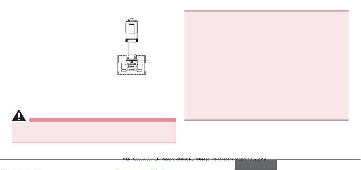
2.2 Isolation
The device must not be isolated more than
2cm from the body edge upwards to the
actuator.
max. 2 cm
3 BASIC SAFETY INSTRUCTIONS
These safety instructions do not make allowance for any contingencies and events which may arise during installation, operation
and maintenance.
Risk of injury from high pressure.
▶ Before loosening lines or valves, switch o the pressure and
drain the lines.
Risk of injury due to electric shock.
▶ Before reaching into the device or the system, switch o the power
supply and secure to prevent reactivation! Observe the applicable
accident prevention and safety regulations for electrical devices.
Risk of burns or risk of re.
Continuous operation or hot media may result in a hot device
surface.
▶ Keep the device away from highly ammable substances and
media and do not touch with bare hands!
▶ Do not obstruct heat dissipation required for operation.
Risk of injury due to cold, hot and aggressive media.
Heat sources or temperature uctuations may cause malfunctions
or leaks.
▶ Avoid heat sources which may cause the permissible tempera-
ture range to be exceeded.
▶ Check the media resistance before use.
english
3
Page 4
Danger due to low and high temperatures.
Depending on the media temperature, the device can become
extremely cold or extremely hot.
▶ Keep the device away from substances sensitive to cold and
highly ammable substances and do not touch with bare
hands.
Destruction of the coil due to overheating
▶ Electrically connect coil with mounted housing only.
▶ In the case of alternating voltage, pay attention to movable
core.
▶ Check media resistance.
General hazardous situations.
To prevent injuries, ensure that:
▶ Do not feed in any aggressive or highly ammable media.
▶ Do not make any internal or external changes to the device.
▶ Secure the system and device against accidental activation.
▶ Installation and maintenance may only be performed by autho-
rised technicians only using the appropriate tools.
▶ After an interruption in the power or pneumatic supply, ensure
that the process is restarted in a dened or controlled manner.
▶ Do not mechanically load housing.
▶ Observe the general rules of technology.
4
english
4 TECHNICAL DATA
The following values are indicated on the type label:
• Voltage, current type, coil power
• Pressure range
• Body material (MS=brass, VA=stainless steel)
• Seal material (PTFE, NBR)
4.1 Conformity
The Type 6026 conforms to the EU directives as per the EU Declaration
of Conformity (if applicable).
4.2 Standards
The applied standards, which are used to demonstrate conformity with
EU directives, are listed in the EU type examination certicate and/or
the EU Declaration of Conformity (if applicable).
4.3 Operating conditions
Ambient temperature max. +50°C
Degree of protection with cable plug: IP65 acc. to EN 60529,
NEMA 4X
Page 5

4.4 Electrical operating conditions
1 (P)
2 (A)
Switching frequency
Relative duty cycle [%]
Ambient temperature [°C]
Operating mode
(acc. to DIN VDE 0580)
Minimum duty cycle
Minimum currentless
break
Switching time
With AC/DC high-performance electronics
Continuous operation
Intermittent operation (To determine the permissible operating parameters, see “Chapter
4.4” and “Chapter 4.7”)
1 s
1 s
approx. 500 ms
Intermittent operation
characteristics for variant
with AC/DC high-performance electronics
With AC/DC high-performance electronics
Maximum switching
frequency
Maximum relative duty
cycle
see “Diagram of electrical operating conditions”
4.5 Fluidic data
Medium temperature –200...+180°C
viscosity 21mm²/s
Media neutral gaseous and liquid media that do not
attack the body and seal materials (see resistance table: www.burkert.com). Check resistance in each individual case.
Circuit function (CF)
Circuit function A
(NC)
2/2-way valve, 1 (P) normally
closed
english
5
Page 6

4.6 Mechanical data
Port connections G¼, G½, G⅜
Materials
Body:
Identication MS Brass body, valve seat 1.4305
brass body, brass valve seat
Identication VA Body and valve seat 1.4410
Actuator: Epoxide
Seal material: PTFE
Dimensions see data sheet
4.7 Electrical data
Connections DIN EN 175301-803 Form A:
for cable plug Type 2508
Operating voltage see type label
Voltage tolerance ±10%
Nominal power 8W operation, 85W inrush
Switching frequency max. 10/min
O time t
2 switch-on procedures min. 1s
between
off
6
english
Page 7

Intermittent operation for variant with AC/DC high-performance
electronics
Characteristics (acc. to DIN VDE 0580)
tSD – cycle time
tED – duty cycle
t
ED
t
SP
t
SD
tSD [s] =
tED [s] =
t
SP
60
SH
ED[%]
100
[s] = tSD [s] – tED [s]
tSP – currentless break
ED – relative duty
1
min
SH – switching
x
t
[s]
SD
cycle
frequency
4.8 Type label (example)
Seat orice
Circuit function
Type
Identication number
Seal material
Body material
Connection,
pressure range
Voltage, frequency, output
CE marking
english
7
Page 8

5 INSTALLATION
DANGER!
Risk of injury from high pressure in the system.
▶ Before loosening lines and valves, turn o the pressure and
drain the lines!
Risk of injury due to electric shock.
▶ Before reaching into the system, switch o the power supply
and secure to prevent reactivation.
▶ Observe the applicable accident prevention and safety regula-
tions for electrical devices.
WARNING!
5.1 Fluid installation
Installation position: any, preferably coil or actuator face up.
→ Clean pipelines and ange connections.
→ Install dirt trap at the valve inlet (0.2...0.4 mm).
Note the ow direction of the valve. The arrow on the body
indicates the ow direction.
Arrow indicating
ow direction
Risk of injury due to improper installation.
▶ Installation may be carried out by authorised technicians only
and with the appropriate tools.
Risk of injury due to unintentional activation of the system and
uncontrolled restart.
▶ Secure the system against unintentional activation.
▶ Following installation, ensure a controlled restart.
8
english
NOTE!
Caution: Risk of breakage.
▶ Do not use the coil or actuator as a lever arm.
Threaded connection:
→ Hold the valve body using a matching open-end wrench and
screw into the pipeline.
Page 9

5.2 Electrical installation
WARNING!
Risk of injury due to electric shock.
▶ Before reaching into the system, switch o the power supply
and secure to prevent reactivation.
▶ Observe the applicable accident prevention and safety regula-
tions for electrical devices.
If there is no protective conductor function between the coil and
body, there is a risk of electric shock.
▶ Always connect protective conductor.
▶ Check electrical continuity between coil and body.
Observe voltage and current type according to type label.
Only for variant with terminal connection box:
• Connect a maximum of one conductor per terminal point
• The maximum connection cable cross-section is 2.5 mm² / AWG 14
• Remove insulation on the wires to a maximum length of 6 mm
• Tighten the terminal screws with 0.25 Nm
• Close the housing lid properly and tighten the lock screw with 2 Nm
• Check the consistency of the protective conductor connection
Item Symbol Pin assignment
1
2
1
2
L N + -
N L - +
→ Check that seal is correctly tted.
→ Screw cable plug tightly onto the coil
(max. 1 Nm).
3
3
english
PE
9
Page 10

5.3 Rotating the solenoid
WARNING!
6 MAINTENANCE, TROUBLESHOOTING
WARNING!
Risk of injury due to electric shock.
If there is no protective conductor function between the coil and
body, there is a risk of electric shock.
▶ Check the protective conductor function after installing the coil.
Overheating, risk of re.
Connecting the coil without rst installing the valve will lead to
overheating and will destroy the coil.
▶ Only connect the coil after the valve has been installed.
The coil can be rotated by 4 x 90°.
→ Loosen nut.
Nut
(max. 5 Nm).
4 x 90°
→ Rotate the solenoid.
→ Use a matching open-end wrench to
tighten the nut (max. 5 Nm).
10
english
Valve
Risk of injury due to improper maintenance work.
▶ Maintenance may be carried out by authorised technicians only
and with the appropriate tools.
Risk of injury due to unintentional activation of the system and
uncontrolled restart.
▶ Secure the system against unintentional activation.
▶ Following maintenance, ensure a controlled restart.
Check in case of faults:
• Port connections
• Operating pressure
• Operating voltage
If the valve still does not switch, contact your local Bürkert Service
representative.
Page 11

7 DISASSEMBLY
DANGER!
Risk of injury from high pressure in the system.
▶ Before loosening lines and valves, turn o the pressure and
drain the lines!
Risk of injury due to electric shock.
▶ Before reaching into the system, switch o the power supply
and secure to prevent reactivation.
▶ Observe the applicable accident prevention and safety regula-
tions for electrical devices.
WARNING!
Risk of injury due to improper removal.
▶ Disassembly may only be carried out by authorised technicians
using the appropriate tools.
→ Switch o pressure and drain lines.
→ Switch o electrical voltage.
→ Remove cable plug.
→ Hold the valve body using a matching open-end wrench and
unscrew from the pipeline.
8 TRANSPORTATION, STORAGE,
DISPOSAL
NOTE!
Transport damage.
Inadequately protected devices may be damaged during
transport.
▶ Protect the device against moisture and dirt in shock-resistant
packaging during transportation.
▶ Avoid exceeding or dropping below the permitted storage
temperature.
Incorrect storage may damage the device.
▶ Store the device in a dry and dust-free location.
▶ Storage temperature: –20…+70°C.
Damage to the environment caused by device parts contaminated with media.
▶ Dispose of the device and packaging in an environmentally
friendly manner.
▶ Observe applicable disposal and environmental regulations.
english
11
Page 12

Bürkert Fluid Control Systems
Sales Center
Christian-Bürkert-Str. 13-17
D-74653 Ingelfingen
Tel. + 49 (0) 7940 - 10 91 111
Fax + 49 (0) 7940 - 10 91 448
E-mail: info@burkert.com
International address
www.burkert.com
Manuals and data sheets on the Internet: www.burkert.com
Bedienungsanleitungen und Datenblätter im Internet: www.buerkert.de
Instructions de service et fiches techniques sur Internet : www.burkert.fr
© Bürker t Werke GmbH & Co. KG, 2019
Operating Instructions 1907/00_EU-ML_0 0815315 / Original DE
www.burkert.com
 Loading...