

Page 1
Type 5282
2/2-Way Solenoid Valve
2/2-Wege-Magnetventil
Électrovanne à 2/2 voies
Bedienungsanleitung
Manuel d‘utilisation
Operating Instructions
www.burkert.com
International address
www.burkert.com
Manuals and data sheets on the Internet: www.burkert.com
Bedienungsanleitungen und Datenblätter im Internet: www.buerkert.de
Instructions de service et fiches techniques sur Internet : www.buerkert.fr
© Bürker t Werke GmbH , 2013
Operating Instr uctions 1311/20_EU-ML_00803322 / Original DE
Bürkert Fluid Control Systems
Sales Center
Christian-Bürkert-Str. 13-17
D-74653 Ingelfingen
Tel. + 49 (0) 7940 - 10 91 111
Fax + 49 (0) 7940 - 10 91 448
E-mail: info@de.buerkert.com
Voltage 12V or 24V
UL / UR valid with
class 2 power supply only
Page 2
2
1 OPERATING INSTRUCTIONS
The operating instructions contain important information.
▶ Read the operating instructions carefully and follow the safety instruc-
tions in particular, and also observe the operating conditions.
▶ Operating instructions must be available to each user.
▶ The liability and warranty for the product / device are void if the operating
instructions are not followed.
1.1 Symbols
▶ Designates an instruction to prevent risks.
→ designates a procedure which you must carry out.
Warning of injuries:
DANGER!
Imminent danger! Serious or fatal injuries.
WARNING!
Potential danger! Serious or fatal injuries.
CAUTION!
Danger! Minor or moderately severe injuries.
Warns of damage to property:
NOTE!
2 AUTHORIZED USE
Non-authorized use of the solenoid valve type 5282 may be a
hazard to people, nearby equipment and the environment.
• The device is designed to control, shut off and meter neutral media up
to a viscosity of 21 mm
2
/s.
• Provided the cable plug is connected and installed correctly, e.g. Bürkert type 2508, the device satisfies protection class IP65 in accordance
with DIN EN 60529 / IEC 60529.
• During use observe the authorized data, the operating conditions and
conditions of use specified in the contract documents, on the type label
and in the operating instructions, as described in the chapter entitled
“4 Technical data”.
• Correct transportation, correct storage and installation and careful
use and maintenance are essential for reliable and faultless operation.
• Use the device only as intended.
2.1 Restrictions
If exporting the device, observe any existing restrictions.
2.2 Definition of term
In these operating instructions, the term “device” always refers to the Type
5282.
english
3
Risk of injury due to malfunction of valves with alternating current
(AC).
Sticking core causes coil to overheat, resulting in a malfunction.
▶ Monitor process to ensure function is in perfect working order.
Risk of short-circuit/escape of media through leaking screw
joints.
▶ Ensure seals are seated correctly!
▶ Carefully screw valve and connection lines together!
General hazardous situations.
To prevent injury, ensure that:
▶ The device may only be used in the explosion-protected area if an
appropriate additional identification is attached to the type label.
For use observe the additional information enclosed with the device
together with safety instructions for the explosion risk area.
▶ The enclosed UL instructions must be followed in the UL area.
▶ Do not put any loads on the body (e.g. by placing objects on it or
standing on it).
▶ Do not make any external modifications to the device bodies. Do not
paint the body parts or screws.
3 BASIC SAFETY INSTRUCTIONS
These safety instructions do not make allowance for any
• contingencies and events which may arise during the installation, operation and maintenance of the devices.
• local safety regulations - the operator is responsible for observing these
regulations, also with reference to the installation personnel.
Danger - high pressure!
▶ Before loosening the pipes and valves, turn off the pressure and vent
the pipes.
Risk of electric shock!
▶ Before reaching into the device or the equipment, switch off the
power supply and secure to prevent reactivation!
▶ Observe applicable accident prevention and safety regulations for
electrical equipment!
Risk of burns/risk of fire if used for a prolonged switch-on time
through hot device surface!
▶ Keep the device away from highly flammable substances and media
and do not touch with bare hands.
english
4
▶ The system cannot be activated unintentionally.
▶ Installation and repair work may be carried out by authorized technici-
ans only and with the appropriate tools.
▶ After an interruption in the power supply or fluid supply, ensure that
the process is restarted in a defined or controlled manner.
▶ The device may be operated only when in perfect condition and in
consideration of the operating instructions.
Type 5282 was developed with due consideration given to
accepted safety rules and is state-of-the-art. Nevertheless,
dangerous situations may occur.
3.1 Warranty
The warranty is only valid if the device is used as intended in accordance
with the specified application conditions.
3.2 Information on the internet
The operating instructions and data sheets for type 5282 can be found
on the internet at:
www.buerkert.com
Type 5282
4 TECHNICAL DATA
4.1 Operating conditions
The following values* are indicated on the type label:
• Voltage (tolerance ± 10 %) / current type
• Coil power consumption
(active power in W - at operating temperature)
• Pressure range
• Body material brass (MS) or stainless steel (VA)
• Seal material FKM, EPDM, NBR
* see description of type label below
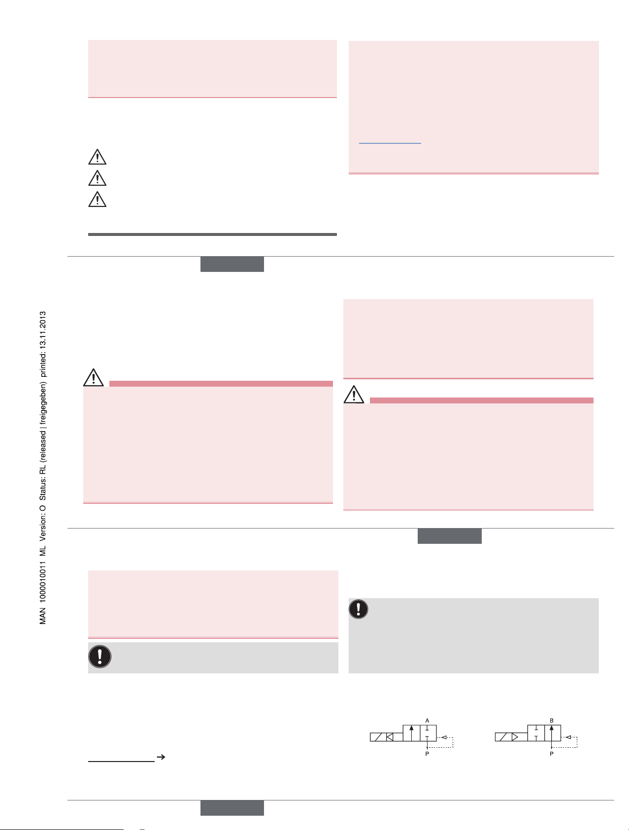
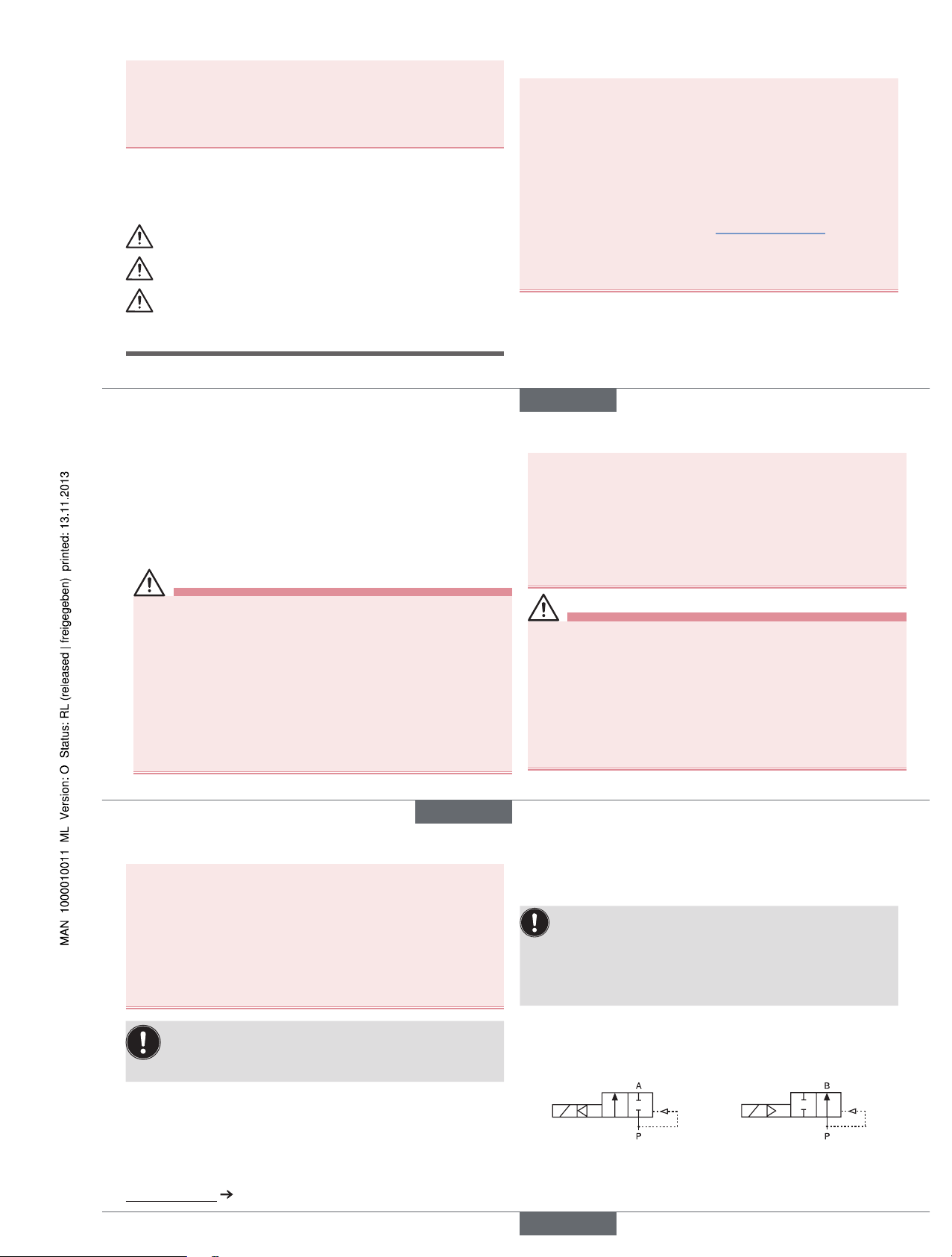
Operating principle 2/2-way valve:
A (NC) B (NO)
Type of protection: IP65 in accordance with DIN EN 60529 / IEC 60529
with correctly connected and installed device socket,
e.g. Bürkert Type 2508
english
Type 5282
Page 3
5
4.2 Application conditions
Ambient temperature: max. +55 °C
Permitted medium temperature and permitted media depending on seal
material:
Seal
material
Medium
temperature
Permitted media
FKM 0 °C ... +90 °C Per-solutions, hot oils without additives,
diesel and heating oil without additives,
detergent solution
EPDM -30 °C ... +90 °C Oil and grease-free liquids,
cold and hot water
NBR 0 °C ... +80 °C Cold and warm water
Operating duration
Unless otherwise indicated on the type label, the solenoid system is suitable
for continuous operation.
Important information for functional reliability during continuous operation: If standstill for a long period at least 1-2 acti-
vations per day are recommended.
Service life
High switching frequency and high pressures reduce the service life.
4.3 Conformity
Type 5282 conforms with the EC Directives according to the EC Declaration of Conformity.
4.4 Standards
The applied standards, which verify conformity with the EC Directives,
can be found on the EC-Type Examination Certificate and / or the EC
Declaration of Conformity.
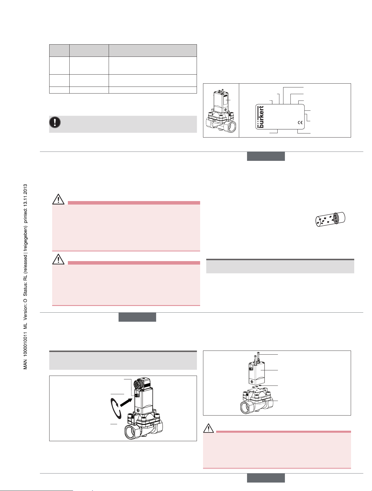
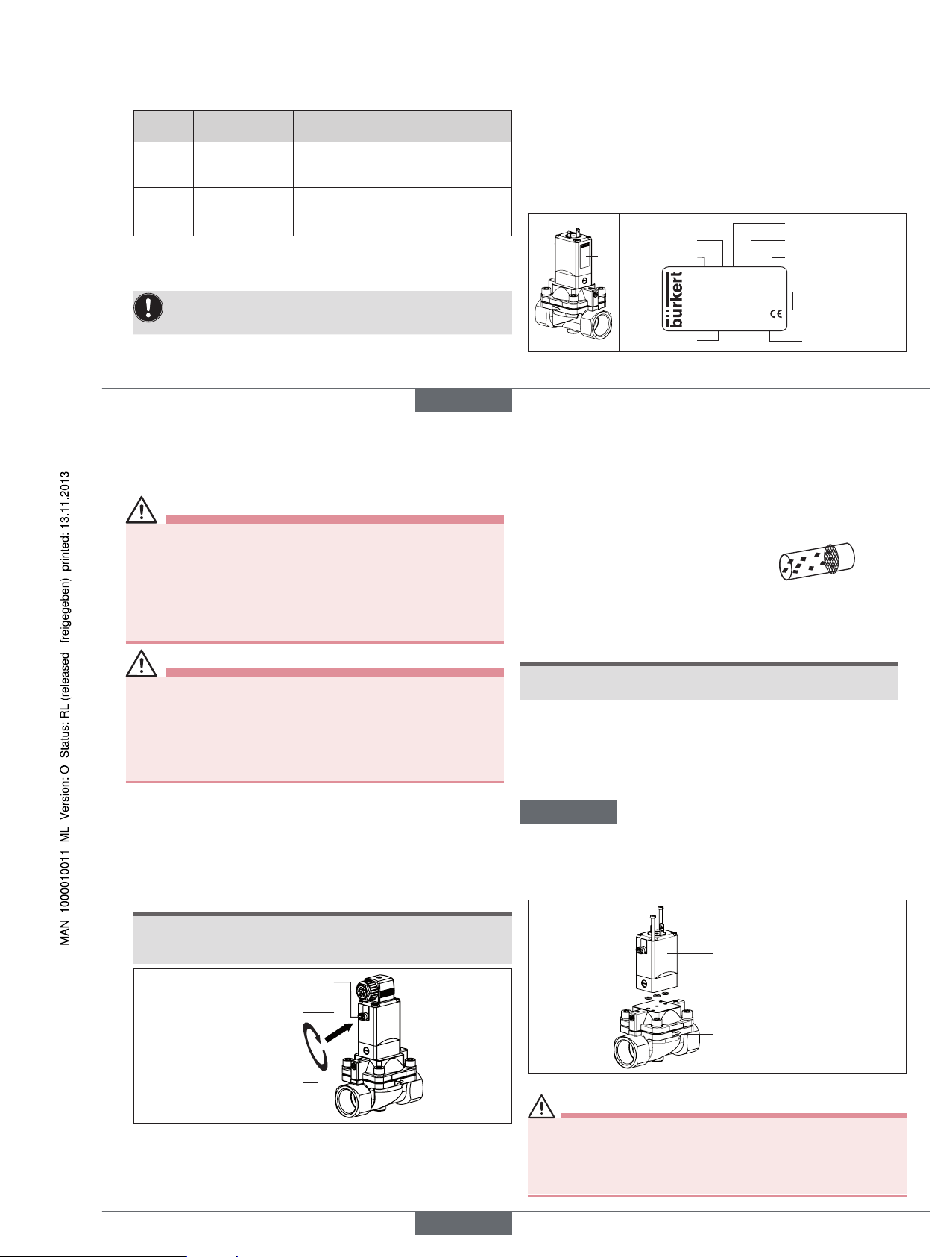
4.5 Type label
Type label
Type
Operating prinziple
Orifice
Seal material
Body material
Id. Number
Manufacturer-Code
Voltage, frequency,
power consumption
Connection thread,
pressure range
Example:
5282 A 25 EPDM MS
Made in Germany
00134469
W17 LU
230V 50-60Hz 8W
G1 1/4 P
N 0,2 - 16 bar
Fig. 1: Location and inscription of the type label
english
6
5 INSTALLATION
5.1 Safety instructions
DANGER!
Risk of injury from high pressure in the equipment!
▶ Before loosening the pipes and valves, turn off the pressure and vent
the pipes.
Risk of injury due to electrical shock!
▶ Before reaching into the device or the equipment, switch off the
power supply and secure to prevent reactivation!
▶ Observe applicable accident prevention and safety regulations for
electrical equipment!
WARNING!
Risk of injury from improper installation!
▶ Installation may be carried out by authorized technicians only and
with the appropriate tools!
Risk of injury from unintentional activation of the system and an
uncontrolled restart!
▶ Secure system from unintentional activation.
▶ Following assembly, ensure a controlled restart.
5.2 Before installation
Installation position:
Installation can be in any position.
Preferably: Actuator upright.
→ Prior to installation check pipelines for dirt and, if required, clean.
Dirt filter: To ensure that the solenoid valve
functions reliably, a dirt filter (≤ 500 µm) must be
installed in front of the valve inlet.
5.3 Installation
→ Hold the device with a suitable tool (open-end wrench) on the body
and screw into the pipeline.
NOTE!
Caution risk of breakage!
• Do not use the coil as a lever arm.
→ Observe direction of flow:
The arrow on the body indicates the direction of flow (no function in
opposite flow direction).
english
7
5.4 Manual emergency actuation
NOTE!
Caution!
• When the manual emergency actuation is locked, the valve can no
longer be actuated electrically.
1
2
Press
Turn
Manual emergency
actuation
Fig. 2: Manual emergency actuation
5.5 Changing valve function
(not possible for var Code CF02 and MT50)
max. 2.0 Nm
Pilot valve
O-rings
Identification for
the flow direction
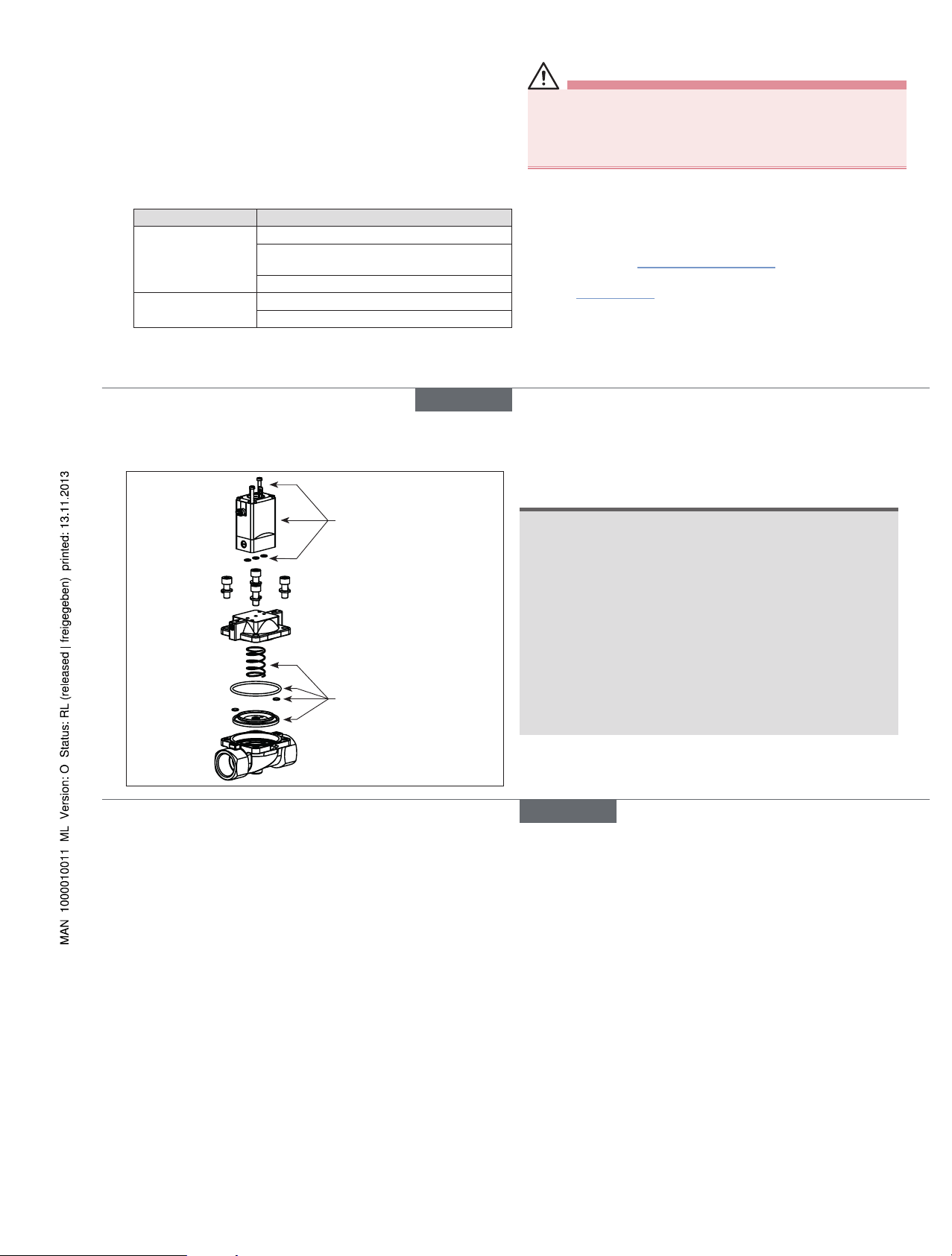
Fig. 3: Installing the pilot valve (changing valve function)
DANGER!
Discharge of medium due to leaking device!
If the O-rings are forgotten or incorrectly inserted during installation
of the pilot valve, the device will be damaged and medium will be
discharged.
• Before screwing in the pilot valve, correctly insert O-rings into the
depressions.
english
Type 5282
Page 4
8
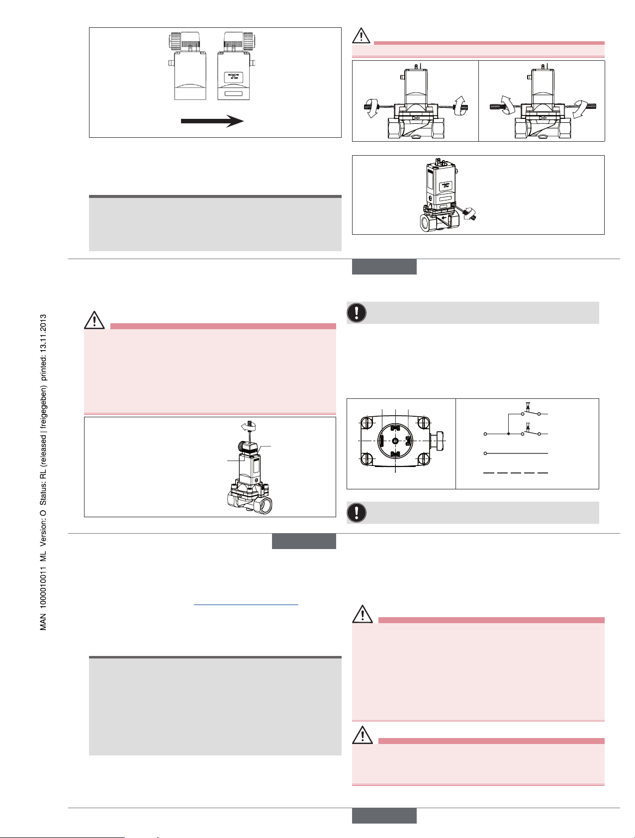
Flow direction
Function NC Function NO
Function NC
The pilot valve is installed in such a way that
the manual emergency
actuation points in the
direction opposite to
the direction of flow
arrow.
Function NO
The pilot valve is installed in such a way
that the manual emergency actuation points
in the same direction as
the identification for the
flow direction.
Fig. 4: Valve functions (NC/NO)
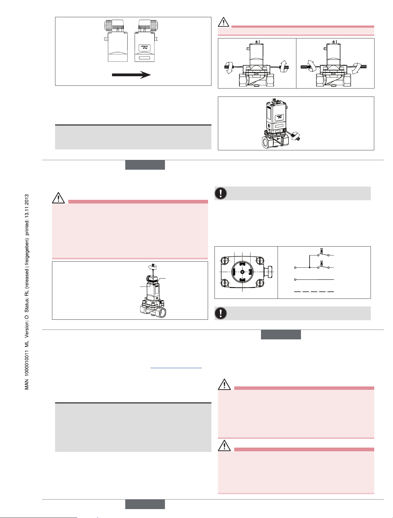
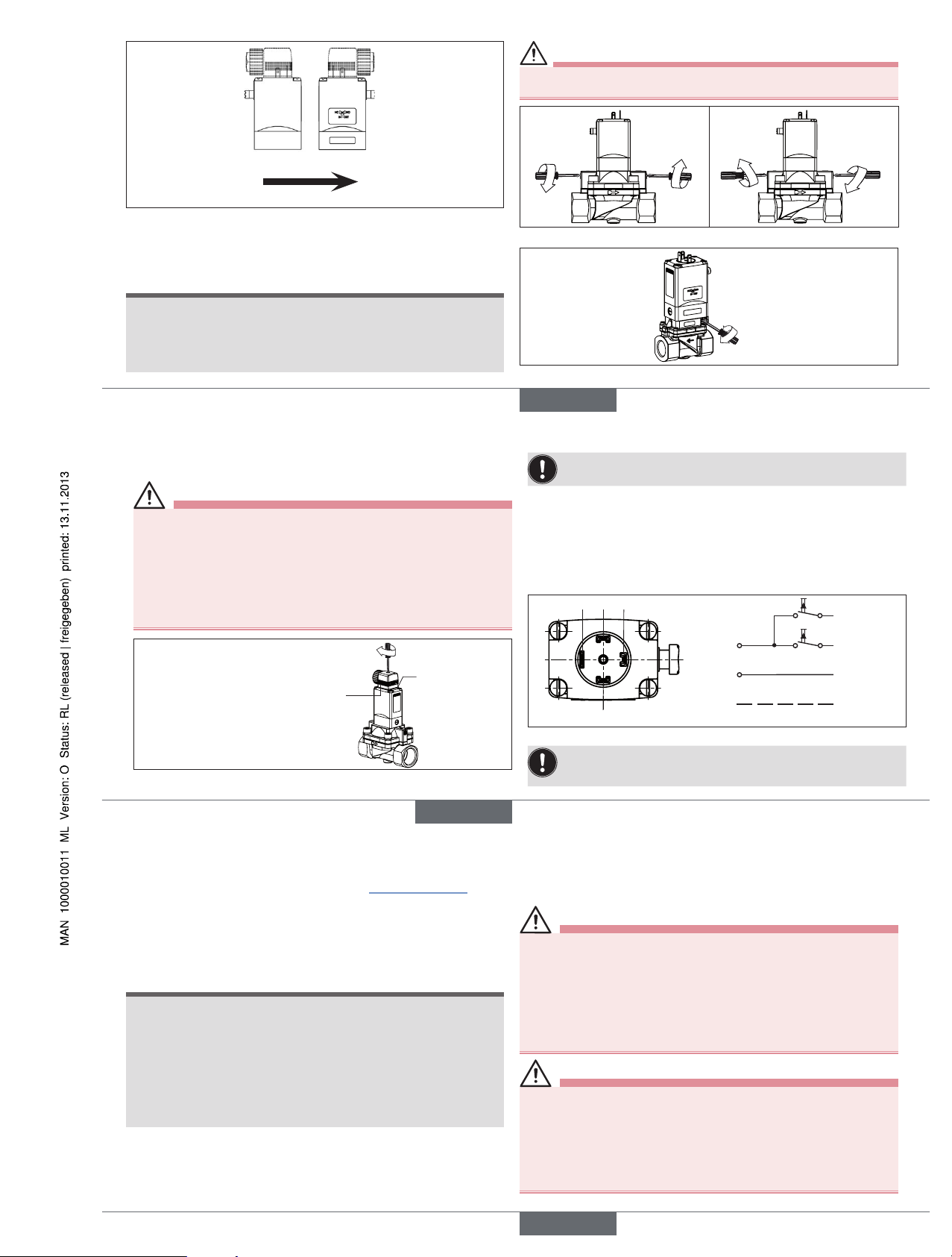
5.6 Setting the switching times
The closing and opening times of the valve can be changed if required with
the side throttle screws.
NOTE!
Pressure surges caused by liquid media and short closing times!
• If closing times are fairly short, liquid media cause higher pressure
surges. These may reduce the service life of the diaphragm and
destroy other devices and components in the system.
CAUTION!
Discharge of medium if the throttle screws are unscrewed too far!
Extending
closing times
Extending
opening times
Reducing
closing times
Reducing
opening times
Fig. 5: Extending / reducing switching times
Extending / reducing
switching times
Fig. 6: Extending / reducing switching times for DN13 stainless steel
english
9
5.7 Electrical connection of the cable plug
DANGER!
Risk of injury due to electrical shock!
▶ Before reaching into the device / equipment switch off the power
supply and secure to prevent reactivation!
▶ Observe applicable accident prevention and safety regulations for
electrical equipment!
If the protective conductor is not connected, there is a risk of electric
shock!
▶ Always connect protective conductor and check electrical continuity
coil and body.
Authorized cable plug e.g.
Type 2508 or other suitable cable
plug in accordance with
DIN EN 175301-803 Form A
max. 1 Nm
Seal
Fig. 7: Electrical connection of the cable plug
Note the voltage and current type as specified on the type label.
→ Tighten cable plug (for permitted types see data sheet), observing
max. torque 1 Nm.
→ Check that seal is fitted correctly.
→ Connect protective conductor and check electrical continuity between
coil and body.
5.7.1 Electrical connection - Pulse (CF 02)
24 3
1
Terminal 1
(=) ∼
(+) L1
(–) N
PE
Terminal 2
Terminal 3
Earth connector
Fig. 8: Circuit diagram
The connection terminals in the device socket are identified with
the numbers 1 to 3 according to the terminals on the valve.
english
10
Procedure:
→ Pulse valves (variable code CF 02) as in “Fig. 8: Circuit diagram”
connect. Pulse to Terminal 1 closes the valve; pulse to Terminal 2
opens the valve.
→ Connect standard version L1/+ or N/– to Terminals 1 and 2 irres-
pective of the polarity.
NOTE!
Important information:
• Avoid emitting pulses simultaneously to both coil windings.
• Do not switch any other consumers (relays, etc.) at the same time as
the terminals.
• The coil connection, to which voltage is not applied, must be galvanically isolated (open).
• If two or more valves are switched in parallel, ensure that this requirement is met by using 2-pole or multi-pole switches.
6 MAINTENANCE,
TROUBLESHOOTING
6.1 Safety instructions
DANGER!
Risk of injury from high pressure in the equipment!
▶ Before loosening the pipes and valves, turn off the pressure and vent
the pipes.
Risk of injury due to electrical shock!
▶ Before reaching into the device or the equipment, switch off the
power supply and secure to prevent reactivation!
▶ Observe applicable accident prevention and safety regulations for
electrical equipment!
WARNING!
Risk of injury from improper maintenance!
▶ Maintenance may be carried out by authorized technicians only and
with the appropriate tools!
Risk of injury from unintentional activation of the system and an
uncontrolled restart!
▶ Secure system from unintentional activation.
▶ Following maintenance, ensure a controlled restart.
english
Type 5282
Page 5
11
6.2 Malfunctions
If malfunctions occur, check whether:
→ the device has been installed according to the instructions,
→ the electrical and fluid connections are correct,
→ the device is not damaged,
→ all screws have been tightened,
→ the voltage and pressure have been switched on,
→ the pipelines are clean.
Malfunction Possible cause
Valve does not switch Short-circuit or coil interrupted
Medium pressure outside the permitted
pressure range
Manual emergency actuation locked
Valve does not close Internal space of the valve is dirty
Manual emergency actuation locked
7 SPARE PARTS
CAUTION!
Risk of injury and/or damage by the use of incorrect parts!
Incorrect accessories and unsuitable spare parts may cause injuries
and damage the device and the surrounding area.
• Use original accessories and original spare parts from Bürkert only.
7.1 Ordering spare parts
Replacement part sets
Order the spare-part set SET 3 or the pilot control with solenoid coil (complete) by quoting the identification number of the device.
• See replacement part sets “7.2 Exploded drawing”.
• The identification number of the device can be found on the type label.
See also chapter “4.5 Type label”.
english
12
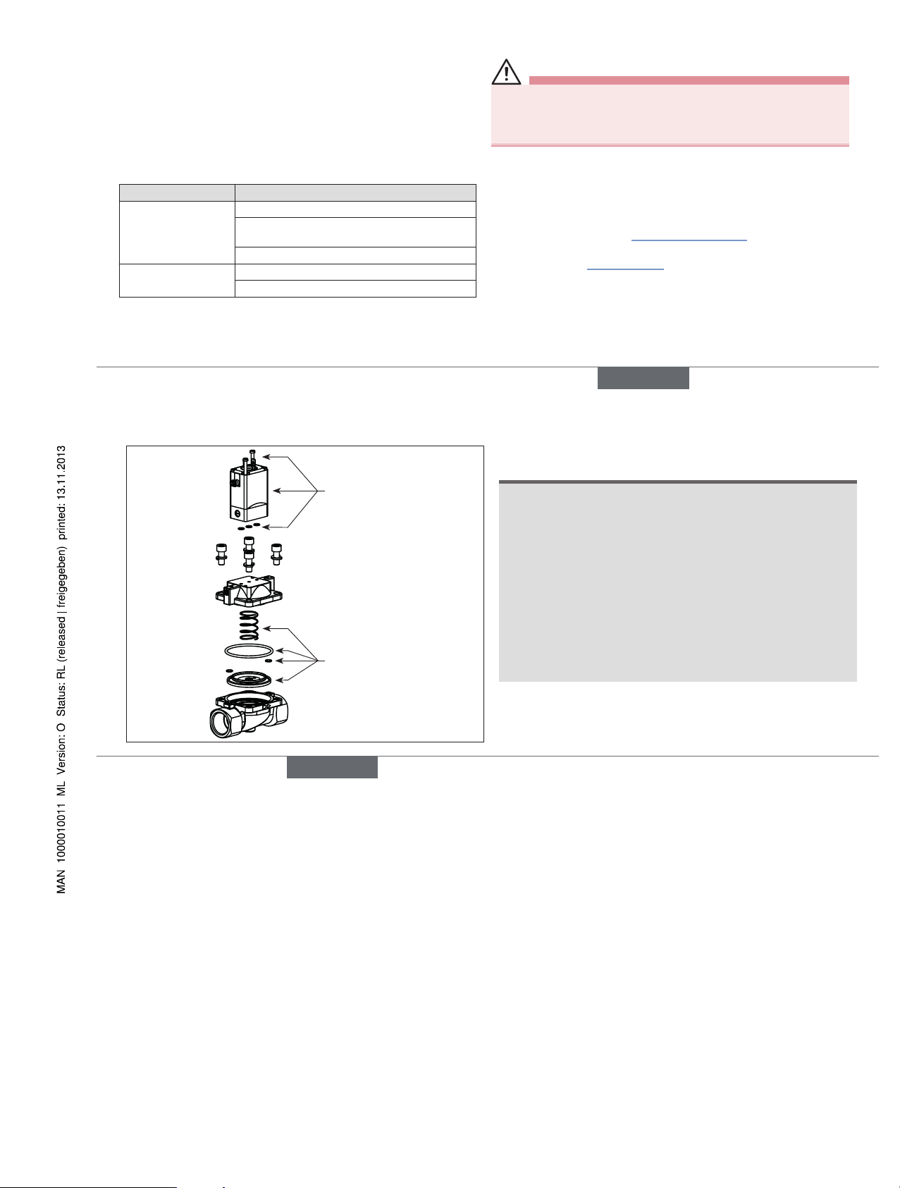
7.2 Exploded drawing
Pilot valve
SET 3
8 TRANSPORT, STORAGE,
DISPOSAL
NOTE!
Transport damages!
Inadequately protected equipment may be damaged during transport.
• During transportation protect the device against wet and dirt in
shock-resistant packaging.
• Avoid exceeding or dropping below the allowable storage
temperature.
Incorrect storage may damage the device.
• Store the device in a dry and dust-free location!
• Storage temperature: -40 °C ... +80 °C
Damage to the environment caused by device components
contaminated with media.
• Observe applicable regulations on disposal and the environment.
• Observe national waste disposal regulations.
→ Dispose of the device and packaging in an environmentally friendly
manner.
english
Type 5282
Page 6

Type 5282
2/2-Way Solenoid Valve
2/2-Wege-Magnetventil
Électrovanne à 2/2 voies
Bedienungsanleitung
Manuel d‘utilisation
Operating Instructions
www.burkert.com
International address
www.burkert.com
Manuals and data sheets on the Internet: www.burkert.com
Bedienungsanleitungen und Datenblätter im Internet: www.buerkert.de
Instructions de service et fiches techniques sur Internet : www.buerkert.fr
© Bürker t Werke GmbH , 2013
Operating Instr uctions 1311/20_EU-ML_00803322 / Original DE
Bürkert Fluid Control Systems
Sales Center
Christian-Bürkert-Str. 13-17
D-74653 Ingelfingen
Tel. + 49 (0) 7940 - 10 91 111
Fax + 49 (0) 7940 - 10 91 448
E-mail: info@de.buerkert.com
Page 7
13
1 DIE BEDIENUNGSANLEITUNG
Die Bedienungsanleitung enthält wichtige Informationen.
▶ Bedienungsanleitung sorgfältig lesen und Hinweise zur Sicherheit
beachten.
▶ Bedienungsanleitung muss jedem Benutzer zur Verfügung stehen.
▶ Haftung und Gewährleistung für das Produkt / Gerät entfällt, wenn die
Anweisungen der Bedienungsanleitung nicht beachtet werden.
1.1 Darstellungsmittel
▶ markiert eine Anweisung zur Gefahrenvermeidung.
→ markiert einen Arbeitsschritt, den Sie ausführen müssen.
Warnung vor Verletzungen:
GEFAHR!
Unmittelbare Gefahr! Schwere oder tödliche Verletzungen.
WARNUNG!
Mögliche Gefahr! Schwere oder tödliche Verletzungen.
VORSICHT!
Gefahr! Leichte oder mittelschwere Verletzungen.
Warnung vor Sachschäden:
HINWEIS!
2 BESTIMMUNGSGEMÄSSE
VERWENDUNG
Bei nicht bestimmungsgemäßem Einsatz des Typs 5282 können
Gefahren für Personen, Anlagen in der Umgebung und die
Umwelt entstehen.
• Das Gerät ist zum Steuern, Absperren und Dosieren von neutralen
Medien bis zu einer Viskosität von 21 mm
2
/s konzipiert.
• Mit einer sachgemäß angeschlossenen und montierten Gerätesteckdose, z. B. Bürkert Typ 2508 erfüllt das Gerät die Schutzart IP65 nach
DIN EN 60529 / IEC 60529.
• Für den Einsatz die in den Vertragsdokumenten und der Bedienungsanleitung spezifizierten zulässigen Daten, Betriebs- und Einsatzbedingungen beachten. Diese sind im Kapitel „4 Technische Daten“ beschrieben.
• Voraussetzungen für den sicheren und einwandfreien Betrieb sind
sachgemäßer Transport, sachgemäße Lagerung und Installation sowie
sorgfältige Bedienung und Instandhaltung.
• Das Gerät nur bestimmungsgemäß einsetzen.
2.1 Beschränkungen
Beachten Sie bei Ausfuhr des Geräts gegebenenfalls bestehende
Beschränkungen.
2.2 Begriffsdefinition
Der in der Anleitung verwendete Begriff „Gerät“ steht immer für Typ 5282.
deutsch
14
Verletzungsgefahr durch Funktionsausfall bei Ventilen mit
Wechselspannung (AC)!
Festsitzender Kern bewirkt Spulenüberhitzung, die zu Funktionsausfall
führt.
▶ Arbeitsprozess auf einwandfreie Funktion überwachen.
Kurzschlussgefahr/Austritt von Medium durch undichte
Verschraubungen!
▶ Auf einwandfreien Sitz der Dichtungen achten.
▶ Ventil und Anschlussleitungen sorgfältig verschrauben.
Allgemeine Gefahrensituationen.
Zum Schutz vor Verletzungen ist zu beachten:
▶ Im explosionsgeschützten Bereich darf das Gerät nur eingesetzt
werden, wenn auf dem Typschild eine entsprechende zusätzliche
Kennzeichnung angebracht ist. Für den Einsatz muss die dem Gerät
beiliegende Zusatzinformation mit Sicherheitshinweisen für den Ex-
Bereich beachtet werden.
▶ Im UL-Bereich muss die beiliegende UL-Anleitung beachtet werden.
▶ Belasten Sie das Gehäuse nicht mechanisch (z. B. durch Ablage
von Gegenständen oder als Trittstufe).
3 GRUNDLEGENDE
SICHERHEITSHINWEISE
Diese Sicherheitshinweise berücksichtigen keine
• Zufälligkeiten und Ereignisse, die bei Montage, Betrieb und Wartung
der Geräte auftreten können.
• ortsbezogenen Sicherheitsbestimmungen, für deren Einhaltung, auch in
Bezug auf das Montagepersonal, der Betreiber verantwortlich ist.
Gefahr durch hohen Druck!
▶ Vor dem Lösen von Leitungen und Ventilen den Druck abschalten und
Leitungen entlüften.
Gefahr durch elektrische Spannung!
▶ Vor Eingriffen in das Gerät oder die Anlage Spannung abschalten
und vor Wiedereinschalten sichern.
▶ Die geltenden Unfallverhütungs- und Sicherheitsbestimmungen für
elektrische Geräte beachten.
Verbrennungsgefahr/Brandgefahr bei Dauerbetrieb durch heiße
Geräteoberfläche!
▶ Das Gerät von leicht brennbaren Stoffen und Medien fernhalten und
nicht mit bloßen Händen berühren.
deutsch
15
▶ Nehmen Sie keine äußerlichen Veränderungen an den Gerätegehäu-
sen vor. Gehäuseteile und Schrauben nicht lackieren.
▶ Dass die Anlage nicht unbeabsichtigt betätigt werden kann.
▶ Installations- und Instandhaltungsarbeiten dürfen nur von autorisier-
tem Fachpersonal mit geeignetem Werkzeug ausgeführt werden.
▶ Nach einer Unterbrechung der elektrischen oder pneumatischen
Versorgung ist ein definierter oder kontrollierter Wiederanlauf des
Prozesses zu gewährleisten.
▶ Das Gerät darf nur in einwandfreiem Zustand und unter Beachtung
der Bedienungsanleitung betrieben werden.
Das Magnetventil Typ 5282 wurde unter Einbeziehung der
anerkannten sicherheitstechnischen Regeln entwickelt und
entspricht dem Stand der Technik. Trotzdem können Gefahren
entstehen.
3.1 Gewährleistung
Voraussetzung für die Gewährleistung ist der bestimmungsgemäße Gebrauch
des Geräts unter Beachtung der spezifizierten Einsatzbedingungen.
3.2 Informationen im Internet
Bedienungsanleitungen und Datenblätter zum Typ 5282 finden Sie im
Internet unter:
www.buerkert.de
Typ 5282
4 TECHNISCHE DATEN
4.1 Betriebsbedingungen
Folgende Werte* sind auf dem Typschild angegeben:
• Spannung (Toleranz ± 10 %) / Stromart
• Spulenleistung (Wirkleistung in W – betriebswarm)
• Druckbereich
• Gehäusewerkstoff Messing (MS) oder Edelstahl (VA)
• Dichtwerkstoff FKM, EPDM, NBR
* siehe nachfolgende Typschildbeschreibung
Wirkungsweise 2/2-Wege-Ventil:
A (NC) B (NO)
Schutzart: IP65 nach DIN EN 60529 / IEC 60529
mit sachgemäß angeschlossener und montierter
Gerätesteckdose, z. B. Bürkert Typ 2508
deutsch
Typ 5282
Page 8
16
4.2 Einsatzbedingungen
Umgebungstemperatur: max. +55 °C
Zulässige Mediumstemperatur und zulässige Medien in Abhängigkeit
vom Dichtwerkstoff:
Dichtwerkstoff
Mediumstemperatur
Zulässige Medien
FKM 0 °C ... +90 °C Per-Lösungen, heiße Öle ohne Additive,
Diesel und Heizöl ohne Additive,
Waschlauge
EPDM -30 °C ... +90 °C Öl- und fettfreie Flüssigkeiten, Kalt- und
Heißwasser
NBR 0 °C ... +80 °C Kalt- und Warmwasser
Betriebsdauer
Wenn auf dem Typschild nicht anders angegeben, ist das Magnetsystem
für Dauerbetrieb geeignet.
Wichtiger Hinweis zur Funktionssicherheit bei Dauerbetrieb!
Bei langem Stillstand wird eine Mindestbetätigung von
1–2 Schaltungen pro Tag empfohlen.
Lebensdauer
Hohe Schaltfrequenz und hohe Drücke verringern die Lebensdauer.
4.3 Konformität
Der Typ 5282 ist konform zu den EG-Richtlinien entsprechend der
EG-Konformitätserklärung.
4.4 Normen
Die angewandten Normen, mit denen die Konformität mit den EG-Richtlinien nachgewiesen wird, sind in der EG-Baumusterprüfbescheinigung
und/oder der EG-Konformitätserklärung nachzulesen.
4.5 Typschild
Typschild
Typ
Wirkungsweise
Nennweite
Dichtwerkstoff
Gehäusewerkstoff
Identnummer
Hersteller-Code
Spannung,
Frequenz, Leistung
Anschlussart,
Druckbereich
Beispiel:
5282 A 25 EPDM MS
Made in Germany
00134469
W17 LU
230V 50-60Hz 8W
G1 1/4 P
N 0,2 - 16 bar
Bild 1: Lage und Beschriftung des Typschilds
deutsch
17
5 MONTAGE
5.1 Sicherheitshinweise
GEFAHR!
Verletzungsgefahr durch hohen Druck in der Anlage!
▶ Vor dem Lösen von Leitungen oder Ventilen den Druck abschalten
und Leitungen entlüften.
Verletzungsgefahr durch Stromschlag!
▶ Vor Eingriffen in das Gerät oder die Anlage Spannung abschalten
und vor Wiedereinschalten sichern!
▶ Die geltenden Unfallverhütungs- und Sicherheitsbestimmungen für
elektrische Geräte beachten!
WARNUNG!
Verletzungsgefahr bei unsachgemäßer Montage!
▶ Die Montage darf nur autorisiertes Fachpersonal mit geeignetem
Werkzeug durchführen!
Verletzungsgefahr durch ungewolltes Einschalten der Anlage und
unkontrollierten Wiederanlauf!
▶ Anlage vor unbeabsichtigtem Betätigen sichern.
▶ Nach der Montage einen kontrollierten Wiederanlauf gewährleisten.
5.2 Vor dem Einbau
Einbaulage:
Die Einbaulage ist beliebig. Vorzugsweise: Antrieb oben.
→ Rohrleitungen vor dem Einbau auf Verschmutzungen überprüfen und
gegebenenfalls reinigen.
Schmutzfilter: Für die sichere Funktion des
Magnetventils muss vor dem Ventileingang ein
Schmutzfilter (≤ 500 µm) eingebaut werden.
5.3 Einbau
→ Das Gerät mit geeignetem Werkzeug (Gabelschlüssel) am Gehäuse
festhalten, in die Rohrleitung einschrauben.
HINWEIS!
Vorsicht Bruchgefahr!
• Die Spule darf nicht als Hebelarm benutzt werden.
→ Durchflussrichtung beachten:
Der Pfeil auf dem Gehäuse kennzeichnet die Durchflussrichtung
(keine Funktion in entgegengesetzter Durchflussrichtung).
deutsch
18
5.4 Handnotbetätigung
HINWEIS!
Vorsicht!
• Bei arretierter Handnotbetätigung kann das Ventil elektrisch nicht
mehr betätigt werden.
1
2
Drücken
Drehen
Handnotbetätigung
Bild 2: Handnotbetätigung
5.5 Ventilfunktion ändern
(nicht möglich bei var Code CF02 und MT50)
max. 2,0 Nm
Vorsteuerventil
O-Ringe
Kennzeichnung der
Durchflussrichtung
Bild 3: Montage des Vorsteuerventils (Ventilfunktion ändern)
GEFAHR!
Mediumsaustritt durch undichtes Gerät!
Werden bei der Montage des Vorsteuerventils die O-Ringe vergessen
oder unkorrekt eingesetzt, führt das zur Beschädigung des Geräts und
Mediumsaustritt.
▶ O-Ringe vor dem Verschrauben korrekt in die Vertiefungen einsetzen.
deutsch
Typ 5282
Page 9
19
Durchflussrichtung
Funktion NC Funktion NO
Funktion NC
(stromlos geschlossen)
Das Vorsteuerventil
wird so montiert, dass
die Handnotbetätigung
in die entgegengesetzte Richtung zeigt
wie der Durchflussrichtungspfeil.
Funktion NO
(stromlos geöffnet)
Das Vorsteuerventil
wird so montiert, dass
die Handnotbetätigung in die gleiche
Richtung zeigt wie die
Kennzeichnung der
Durchflussrichtung.
Bild 4: Ventilfunktionen (NC/NO)
5.6 Einstellung der Schaltzeiten
Die Schließ- und Öffnungszeiten des Ventils können an den seitlichen
Drosselschrauben bei Bedarf verändert werden.
HINWEIS!
Schließschläge bei flüssigen Medien und kurzen Schließzeiten!
• Bei kürzeren Schließzeiten treten bei flüssigen Medien höhere
Schließschläge auf. Diese können eine Verkürzung der Membranlebensdauer zur Folge haben und andere Geräte und Komponenten
in der Anlage zerstören.
VORSICHT!
Mediumsaustritt bei zu weitem Herausdrehen der
Drosselschrauben!
Schließzeiten
verlängern
Öffnungszeiten
verlängern
Schließzeiten
verkürzen
Öffnungszeiten
verkürzen
Bild 5: Schaltzeiten verlängern / verkürzen
Schaltzeiten
verlängern / verkürzen
Bild 6: Schaltzeiten verlängern / verkürzen für DN13 VA
deutsch
20
5.7 Elektrischer Anschluss der
Gerätesteckdose
GEFAHR!
Verletzungsgefahr durch Stromschlag!
▶ Vor Eingriffen in das Gerät oder die Anlage Spannung abschalten
und vor Wiedereinschalten sichern!
▶ Die geltenden Unfallverhütungs- und Sicherheitsbestimmungen für
elektrische Geräte beachten!
Bei nicht angeschlossenem Schutzleiter besteht Stromschlaggefahr!
▶ Schutzleiter immer anschließen und elektrischen Durchgang zwi-
schen Spule und Gehäuse prüfen.
Zugelassene Gerätesteckdose
z. B. Typ 2508 oder andere
geeignete Gerätesteckdose nach
DIN EN 175301-803 Form A
max. 1 Nm
Dichtung
Bild 7: Elektrischer Anschluss der Gerätesteckdose
Spannung und Stromart laut Typschild beachten.
→ Gerätesteckdose (zugelassene Typen siehe Datenblatt) festschrauben,
dabei maximalen Drehmoment 1 Nm beachten.
→ Korrekten Sitz der Dichtung überprüfen.
→ Schutzleiter anschließen und elektrischen Durchgang zwischen Spule
und Gehäuse prüfen.
5.7.1 Elektrischer Anschluss - Impuls (CF 02)
24 3
1
Klemme 1
(=) ∼
(+) L1
(–) N
PE
Klemme 2
Klemme 3
Schutzleiter
Bild 8: Schaltbild
Die Anschlussklemmen in der Gerätesteckdose sind entsprechend den Klemmen am Ventil mit den Ziffern 1 bis 3
gekennzeichnet.
deutsch
21
Vorgehensweise:
→ Impulsventile (variable code CF 02) wie im „Bild 8: Schaltbild“
anschließen. Impuls auf Klemme 1 schließt das Ventil, Impuls auf
Klemme 2 öffnet das Ventil.
→ Standardausführung L1/+ bzw. N/– an Klemmen 1 und 2 unab-
hängig von der Polung anschließen.
HINWEIS!
Wichtige Hinweise:
• Gleichzeitige Impulsgabe auf beide Spulenwicklungen vermeiden.
• Parallel zu den Klemmen dürfen keine weiteren Verbraucher (Relais
und dergl.) geschaltet werden.
• Der jeweils nicht spannungsbeaufschlagte Spulenanschluss muss
galvanisch getrennt (offen) sein.
• Sollten zwei oder mehr Ventile parallel geschaltet werden, ist durch
Verwendung von 2- oder mehrpoligen Schaltern sicherzustellen,
dass diese Forderung erfüllt ist.
6 WARTUNG, FEHLERBEHEBUNG
6.1 Sicherheitshinweise
GEFAHR!
Verletzungsgefahr durch hohen Druck in der Anlage!
▶ Vor dem Lösen von Leitungen oder Ventilen den Druck abschalten
und Leitungen entlüften.
Verletzungsgefahr durch Stromschlag!
▶ Vor Eingriffen in das Gerät oder die Anlage Spannung abschalten
und vor Wiedereinschalten sichern!
▶ Die geltenden Unfallverhütungs- und Sicherheitsbestimmungen für
elektrische Geräte beachten!
WARNUNG!
Verletzungsgefahr bei unsachgemäßer Installation!
▶ Die Installation darf nur autorisiertes Fachpersonal mit geeignetem
Werkzeug durchführen!
Verletzungsgefahr durch ungewolltes Einschalten der Anlage und
unkontrollierten Wiederanlauf!
▶ Anlage vor unbeabsichtigtem Betätigen sichern.
▶ Nach der Wartung einen kontrollierten Wiederanlauf gewährleisten.
deutsch
Typ 5282
Page 10
22
6.2 Störungen
Überprüfen Sie bei Störungen ob
→ das Gerät vorschriftsmäßig installiert ist,
→ der elektrische und fluidische Anschluss ordnungsgemäß ausgeführt
ist,
→ das Gerät nicht beschädigt ist,
→ alle Schrauben fest angezogen sind,
→ Spannung und Druck anliegen,
→ die Rohrleitungen schmutzfrei sind.
Störung Mögliche Ursache
Ventil schaltet nicht Kurzschluss oder Spulenunterbrechung
Mediumsdruck außerhalb des zulässigen
Druckbereichs
Handnotbetätigung arretiert
Ventil schließt nicht Innenraum des Ventils verschmutzt
Handnotbetätigung arretiert
7 ERSATZTEILE
VORSICHT!
Verletzungsgefahr, Sachschäden durch falsche Teile!
Falsches Zubehör und ungeeignete Ersatzteile können Verletzungen
und Schäden am Gerät und dessen Umgebung verursachen.
▶ Nur Originalzubehör sowie Originalersatzteile der Firma Bürkert
verwenden.
7.1 Ersatzteile bestellen
Ersatzteile
Bestellen Sie den Ersatzteilsatz SET 3 oder die Vorsteuerung mit Magnetspule (komplett) unter der Identnummer des Geräts.
• Ersatzteilsatz siehe „7.2 Explosionszeichnung“.
• Die Identnummer des Geräts finden Sie auf dem Typschild. Siehe auch
Kapitel „4.5 Typschild“.
deutsch
23
7.2 Explosionszeichnung
Vorsteuerventil
SET 3
8 TRANSPORT, LAGERUNG,
ENTSORGUNG
HINWEIS!
Transportschäden!
Unzureichend geschützte Geräte können durch den Transport
beschädigt werden.
• Gerät vor Nässe und Schmutz geschützt in einer stoßfesten
Verpackung transportieren.
• Eine Über- bzw. Unterschreitung der zulässigen Lagertemperatur
vermeiden.
Falsche Lagerung kann Schäden am Gerät verursachen.
• Gerät trocken und staubfrei lagern!
• Lagertemperatur: –40 °C ... +80 °C
Umweltschäden durch von Medien kontaminierte Geräteteile.
• Geltende Entsorgungsvorschriften und Umweltbestimmungen
einhalten.
• Nationale Abfallbeseitigungsvorschriften beachten.
→ Entsorgen Sie das Gerät und die Verpackung umweltgerecht.
deutsch
Typ 5282
Page 11

Type 5282
2/2-Way Solenoid Valve
2/2-Wege-Magnetventil
Électrovanne à 2/2 voies
Bedienungsanleitung
Manuel d‘utilisation
Operating Instructions
www.burkert.com
International address
www.burkert.com
Manuals and data sheets on the Internet: www.burkert.com
Bedienungsanleitungen und Datenblätter im Internet: www.buerkert.de
Instructions de service et fiches techniques sur Internet : www.buerkert.fr
© Bürker t Werke GmbH , 2013
Operating Instr uctions 1311/20_EU-ML_00803322 / Original DE
Bürkert Fluid Control Systems
Sales Center
Christian-Bürkert-Str. 13-17
D-74653 Ingelfingen
Tel. + 49 (0) 7940 - 10 91 111
Fax + 49 (0) 7940 - 10 91 448
E-mail: info@de.buerkert.com
Page 12

24
1 MANUEL D’UTILISATION
Manuel d’utilisation contiennent des informations importantes.
▶ Lire attentivement ce manuel d’utilisation et respecter les consignes
de sécurité.
▶ Le manuel d’utilisation doit être à disposition de chaque utilisateur.
▶ Nous déclinons toute responsabilité et n’accordons aucune garantie
légale pour le produit / l’appareil en cas de non-respect des instruc-
tions figurant dans ce manuel d’utilisation.
1.1 Symbols
▶ Identifie une instruction visant à éviter un danger.
→ identifie une opération que vous effectuer.
Mise en garde contre les blessures :
DANGER !
Danger imminent ! Les blessures graves ou mortelles.
AVERTISSEMENT !
Danger possible ! Les blessures graves ou mortelles.
ATTENTION !
Danger ! Les blessures légères ou moyennement graves.
Met en garde contre des dommages matériels :
REMARQUE !
2 UTILISATION CONFORME
L’utilisation non-conforme du type 5282 peut présenter des dangers
pour les personnes, les installations avoisinantes et l’environnement.
• L’appareil est conçu pour commander, arrêter et doser des fluides
neutres jusqu’à une viscosité de 21 mm
2
/s.
• Avec une un connecteur adéquat, par ex. le type 2508 de Bürkert,
connectée et montée de manière conforme, l’appareil est conforme au
type de protection IP65 selon DIN EN 60529 / IEC 60529.
• L’utilisation doit se faire dans le respect des données et des conditions
d’exploitation et d’utilisation spécifiées dans les documents contractuels,
les instructions de service et sur la plaque signalétique. Vous trouverez
une description au chapitre « 4 Caractéristiques techniques ».
• Les conditions pour l’utilisation sûre et parfaite sont un transport, un
stockage et une installation dans les règles ainsi qu’une parfaite utilisation et maintenance.
• Veillez à ce que l’utilisation de l’appareil soit toujours conforme.
2.1 Limitations
Lors de l’exportation de l’appareil, veuillez respecter les limitations
éventuelles existantes.
2.2 Définition du terme appareil
Le terme « appareil » utilisé dans ces instructions désigne toujours la
Electrovanne type 5282.
français
25
Risque de blessure dû à une panne pour les vannes avec
tension alternative (AC).
Un noyau bloqué provoque la surchauffe de la bobine et donc une
panne.
▶ Surveiller le bon fonctionnement du processus de travail !
Risque de court-circuit / de sortie du fluide en présence de
vissages non étanches.
▶ Veiller à l’installation correcte des joints !
▶ Visser soigneusement la vanne et les raccords de la tuyauterie !
Situations dangereuses d’ordre général.
Pour prévenir les blessures, respectez ce qui suit :
▶ L’appareil ne peut être utilisé dans une zone à atmosphère explo-
sive que si un marquage additionnel correspondant se trouve sur
la plaque signalétique. Lors de l’utilisation, il convient de respecter
les informations suplémentaires fournies avec l’appareil et reprenant les consignes de sécurité pour la zone exposée à des risques
d’explosion.
▶ La notice UL jointe doit être respectée dans la zone UL.
▶ Ne soumettez pas le corps à des contraintes mécaniques (par ex.
pour déposer des objets ou en l’utilisant comme marche).
3 CONSIGNES DE SÉCURITÉ
FONDAMENTALES
Ces consignes de sécurité ne tiennent pas compte:
• des hasards et des événements pouvant survenir lors du montage, de
l‘exploitation et de l‘entretien des appareils.
• des prescriptions de sécurité locales que l‘exploitant est tenu de faire
respecter par le personnel chargé du montage
Danger avec haute pression !
▶ Avant de desserrer les tuyauteries et les vannes, coupez la pres-
sion et purgez les conduites.
Danger présenté par la tension électrique !
▶ Avant d’intervenir dans l’appareil ou l’installation, coupez la tension
et empêchez toute remise sous tension par inadvertance !
▶ Veuillez respecter les réglementations en vigueur pour les appa-
reils électriques en matière de prévention des accidents ainsi
qu’en matière de sécurité !
Risque de brûlures / d’incendie lors d’une durée de fonctionnement prolongée dû à la surface brûlante de l’appareil !
▶ Tenez les substances et les fluides facilement inflammables à l’écart de
l’appareil et ne touchez pas ce dernier à mains nues.
français
26
▶ N’apportez pas de modifications à l’extérieur du corps de l’appareil.
Ne laquez pas les pièces du corps et les vis.
▶ L’installation ne peut pas être actionnée par inadvertance.
▶ Les travaux d’installation et de maintenance doivent être effectués
uniquement par des techniciens qualifiés et habilités disposant de
l’outillage approprié.
▶ Après une interruption de l’alimentation électrique ou du fluide, un
redémarrage défini ou contrôlé du process doit être garanti.
▶ L’appareil doit être utilisé uniquement en parfait état et en respec-
tant les instructions de service.
Le modèle 5282 a été développé dans le respect des règles
reconnues en matière de sécurité et correspond à l’état actuel
de la technique. Néanmoins, des risques peuvent se présenter.
3.1 Garantie légale
La condition pour bénéficier de la garantie légale est l’utilisation conforme
du type 5282 dans le respect des conditions d’utilisation spécifiées.
3.2 Informations sur Internet
Vous trouverez sur Internet les instructions de service et fiches techniques
relatives au type :
www.buerkert.fr
Type 5282
4 CARACTÉRISTIQUES TECHNIQUES
4.1 Conditions d’exploitation
Les valeurs suivantes* sont indiquées sur la plaque signalétique :
• Tension (Tolérance ± 10 %) / Type de courant
• Puissance de bobine (Puissance active en W - à l’état chaud)
• Plage de pression
• Matériau du corps Laiton (MS) ou acier inoxydable (VA)
• Matériau du joint FKM, EPDM, NBR
* voir ci-dessous la description de la plaque signalétique
Fonction vanne 2/2:
A (NC) B (NO)
Type de protection: IP65 selon DIN EN 60529 / IEC 60529 avec
une connecteur montée de manière conforme,
par ex. le type 2508 de Bürkert
français
Type 5282
Page 13

27
4.2 Conditions d’utilisation
Température ambiante : max. +55 °C
Température admissible du fluide et fluides utilisables en fonction du
matériau du joint :
Matériau
du joint
Température du
fluide
Fluides admissibles
FKM 0 °C ... +90 °C Solutions perchloréthylène, huiles
chaudes sans additifs, diesel et fioul
sans additif, lessive
EPDM -30 °C ... +90 °C Liquides exempts d’huile et de graisse,
eau froide et brûlant
NBR 0 °C ... +80 °C Eau froide et chaude
Durée de fonctionnement
Si aucune information contraire ne figure sur la plaque signalétique, le
système magnétique est adapté à un fonctionnement continu.
Remarque importante pour la sécurité de fonctionnement
lors d’un fonctionnement continu !
Dans le cas d’un fonctionnement de longue durée, il est recommandé de procéder à 1 - 2 commutations minimum par jour.
Durée de vie
Une fréquence élevée de commutation ainsi que des pressions élevées
réduisent la durée de vie.
4.3 Conformité
Le type 5282 est conforme aux directives CE comme stipulé dans la
déclaration de conformité CE.
4.4 Normes
Les normes appliquées justifiant la conformité aux directives CE peuvent
être consultées dans le certificat d’essai de modèle type CE et / ou la
déclaration de Conformité CE.
4.5 Plaque signalétique
Plaque
signalétique
Type
Fonction
Diamètre nominal
Matériau du joint
Matériau du corps
N° d’identification
Code-fabricant
Tension, fréquence,
puissance
Raccordement,
plage de pression
Exemple :
5282 A 25 EPDM MS
Made in Germany
00134469
W17 LU
230V 50-60Hz 8W
G1 1/4 P
N 0,2 - 16 bar
Fig. 1 : Position et inscription de la plaque signalétique
français
28
5 MONTAGE
5.1 Consignes de sécurité
DANGER !
Risque de blessures avec présence de haute pression dans
l’installation !
▶ Avant de desserrer les tuyauteries et les vannes, coupez la pression
et purgez les conduites.
Risque de choc électrique !
▶ Avant d’intervenir dans l’appareil ou l’installation, coupez la tension et
empêchez toute remise sous tension par inadvertance !
▶ Veuillez respecter les réglementations en vigueur pour les appa-
reils électriques en matière de prévention des accidents ainsi qu’en
matière de sécurité !
AVERTISSEMENT !
Risque de blessures pour montage non conforme !
▶ Le montage doit être effectué uniquement par un personnel qualifié et
habilité disposant de l’outillage approprié !
Risque de blessures dû à la mise en marche involontaire de l’installation et le redémarrage non contrôlé !
▶ Empêchez tout actionnement involontaire de l’installation.
▶ Garantissez un redémarrage contrôlé après le montage.
5.2 Avant le montage
Position de montage :
Position de montage indifférente.
De préférence : système magnétique vers le haut.
→ Préalablement au montage, vérifier si les tuyaux ne présentent pas de
salissures et les nettoyer le cas échéant
Filtre à impuretés : Pour garantir un fonctionnement
fiable de l’électrovanne, il convient de monter un filtre
à impuretés (≤ 500 µm) avant l’entrée de la vanne.
5.3 Montage
→ Maintenez l’appareil sur le corps à l’aide d’un outil approprié (clé à
fourche) et vissez-le dans la tuyauterie.
REMARQUE !
Attention risque de rupture !
• La bobine ne doit pas être utilisée comme levier.
→ Respectez le sens du débit :
La flèche sur le corps indique le sens du débit (Aucun fonctionnement dans le sens de débit inverse).
français
29
5.4 Actionnement manuel d’urgence
REMARQUE!
Attention !
• Lorsque l’actionnement manuel d’urgence est bloqué, l’actionnement électrique de la vanne n’est plus possible.
1
2
Appuyer
Tourner
Actionnement
manuel d’urgence
Fig. 2 : Actionnement manuel d’urgence
5.5 Modifier la fonction de la vanne
(n’est pas possible de var Code CF02 et MT50)
max. 2,0 Nm
Vanne pilote
Joints toriques
Marquage indiquant
le sens du débit
Fig. 3 : Montage de la vanne pilote (modifier la fonction de la vanne)
DANGER!
Sortie de fluide due à la non-étanchéité de l’appareil !
L’oubli ou le mauvais positionnement des joints toriques lors du
montage de la vanne pilote endommage l’appareil et entraîne la sortie
de fluide.
▶ Positionnez correctement les joints toriques dans les creux avant de
visser.
français
Type 5282
Page 14
30
Sens de débit
Fonction NC Fonction NO
Fonction NC
La vanne pilote est
montée de sorte que
l’actionnement manuel
d’urgence soit dirigé
dans le sens opposé
à celui indiqué par
le flèche de sens de
débit.
Fonction NO
La vanne pilote est
montée de sorte que
l’actionnement manuel
d’urgence soit dirigé
dans le même sens
que celui indiqué par
la flèche de sens de
débit.
Fig. 4 : Fonctions de la vanne (NC/NO)
5.6 Réglage des temps de commutation
Si nécessaire, les temps de fermeture et d’ouverture de la vanne peuvent
être modifiés à l’aide des vis d’étranglement placées sur le côté.
REMARQUE !
Coups de bélier en présence de fluides liquides et de temps de
fermeture courts !
• Des coups de bélier importants surviennent avec les fluides liquides
lorsque les temps de fermeture sont courts. Ceux-ci peuvent réduire
la durée de vie de la membrane et détruire d’autres appareils et composants dans l’installation.
ATTENTION !
Sortie de fluide lorsque les vis d’étranglement sont trop dévissées !
Augmenter
les temps de
fermeture
Augmenter
les temps
d’ouverture
Réduire les
temps de
fermeture
Réduire
les temps
d’ouverture
Fig. 5 : Augmenter / réduire les temps de commutation
Augmenter / réduire
les temps de
commutation
Fig. 6 : Augmenter / réduire les temps de commutation pour DN13 acier
inoxydable
français
31
5.7 Raccordement électrique du connecteur
DANGER !
Risque de choc électrique !
▶ Avant d’intervenir dans l’appareil, coupez la tension et empêchez toute
remise sous tension par inadvertance.
▶ Veuillez respecter les réglementations en vigueur pour les appareils
électriques en matière de prévention des accidents ainsi qu’en matière
de sécurité !
Risque de choc électrique lorsque la prise de terre n’est pas raccordée !
▶ Raccordez toujours la prise de terre et contrôlez le passage du cou-
rant entre la bobine et le corps.
Connecteur autorisé par ex.
type 2508 ou autres connecteurs
adéquates selon
DIN EN 175301-803 forme A
max. 1 Nm
Joint
Fig. 7 : Raccordement électrique du connecteur
Respectez la tension et le type de courant selon la plaque
signalétique.
→ Visser le connecteur (types admissibles, voir fiche technique) en
respectant le couple max. de 1 Nm.
→ Vérifier le bon positionnement du joint.
→ Raccorder la prise de terre de protection et vérifier le passage élec-
trique entre la bobine et le corps.
5.7.1 Raccordement électrique - impulsion (CF 02)
24 3
1
Borne 1
(=) ∼
(+) L1
(–) N
PE
Borne 2
Borne 3
Conducteur
de protection
Fig. 8 : Schéma électrique
Les bornes de raccordement dans la prise d’appareil sont identifiées par les chiffres 1 à 3 conformément aux bornes de la vanne.
français
32
Procédure à suivre :
→ Raccorder les vannes à impulsions (code variable CF 02) comme
cela est représenté sur la « Fig. 8 : Schéma électrique ». L’impulsion
sur la borne 1 ferme la vanne, l’impulsion sur la borne 2 l’ouvre.
→ Raccorder la version standard L1/+ ou N/– aux bornes 1 et 2
quelle que soit la polarité.
REMARQUE !
Remarques importantes :
• Éviter de donner des impulsions simultanément sur les deux enroulements de bobine.
• Aucun autre consommateur ne doit être activé en parallèle avec les
bornes (relais et semblables).
• Le raccord de bobine auquel aucune tension n’est appliquée doit
être isolé électriquement (ouvert).
• En cas de montage en parallèle de deux ou plusieurs vannes, il
convient de garantir le respect de cette exigence par l’utilisation
d’interrupteurs bipolaires ou multipolaires.
6 MAINTENANCE, DÉPANNAGE
6.1 Consignes de sécurité
DANGER !
Risque de blessures dû à la présence de haute pression dans
l’installation !
▶ Avant de desserrer les conduites et les vannes, coupez la pression
et purgez l’air des conduites.
Risque de choc électrique !
▶ Avant d’intervenir dans l’appareil, coupez la tension et empêchez
toute remise sous tension par inadvertance.
▶ Veuillez respecter les réglementations en vigueur pour les appareils
électriques en matière de prévention des accidents ainsi qu’en
matière de sécurité !
AVERTISSEMENT !
Risque de blessures dû à des travaux de maintenance non
conformes !
▶ La maintenance doit être effectué uniquement par un personnel
qualifié et habilité disposant de l’outillage approprié !
français
Type 5282
Page 15

33
Risque de blessures dû à la mise en marche involontaire de
l’installation et le redémarrage non contrôlé !
▶ Empêchez tout actionnement involontaire de l’installation.
▶ Garantissez un redémarrage contrôlé après la maintenance.
6.2 Pannes
En présence de pannes, vérifiez
→ si l‘appareil est installé dans les règles,
→ si le raccord électrique et fluide est correct,
→ si l‘appareil n‘est pas endommagé,
→ si toutes les vis sont bien serrées,
→ si la tension et la pression sont disponibles,
→ si les tuyauteries sont propres.
Panne Cause possible
La vanne
ne s’enclenche pas
Court-circuit ou coupure de la bobine
Pression du fluide hors de la plage de pression
autorisée
Actionnement manuel d’urgence bloqué
La vanne ne se ferme
pas
Intérieur de la vanne encrassé
Actionnement manuel d’urgence bloqué
7 PIÈCES DE RECHANGE
ATTENTION !
Risque de blessures, de dommages matériels dus à de mauvaises pièces !
De mauvais accessoires ou des pièces de rechange inadaptées
peuvent provoquer des blessures et endommager l’appareil ou son
environnement.
▶ Utiliser uniquement des accessoires et des pièces de rechange
d’origine de la société Bürkert.
7.1 Commander des pièces de rechange
Jeux de pièces de rechange
Veuillez commander le jeu de pièces de rechange SET 3 ou la commande
pilote avec électrovanne (complète) en indiquant le numéro d’identification
de l’appareil.
• Jeux de pièces de rechange voir « 7.2 Vue éclatée ».
• Vous trouverez le numéro d’identification de l’appareil sur la plaque
signalétique. Voir également le chapitre « 4.5 Plaque signalétique ».
français
34
7.2 Vue éclatée
Vanne pilote
SET 3
8 TRANSPORT, STOCKAGE,
ELIMINATION
REMARQUE !
Dommages dus au transport !
Les appareils insuffisamment protégés peuvent être endommagés
pendant le transport.
• Transportez l’appareil à l’abri de l’humidité et des impuretés et
dans un emballage résistant aux chocs.
• Evitez le dépassement vers le haut ou le bas de la température de
stockage admissible.
Un mauvais stockage peut endommager l’appareil.
• Stockez l’appareil au sec et à l’abri des poussières !
• Température de stockage : -40 °C … +80 °C.
Dommages à l’environnement causés par des pièces d’appareil
contaminées par des fluides.
• Respectez les prescriptions en matière d’élimination des déchets
et de protection de l’environnement en vigueur.
• Respectez les prescriptions nationales en matière d’élimination des
déchets.
→ Eliminez l’appareil et l’emballage dans le respect de l’environnement.
français
Type 5282
 Loading...