

Page 1

Fluid Control Systems
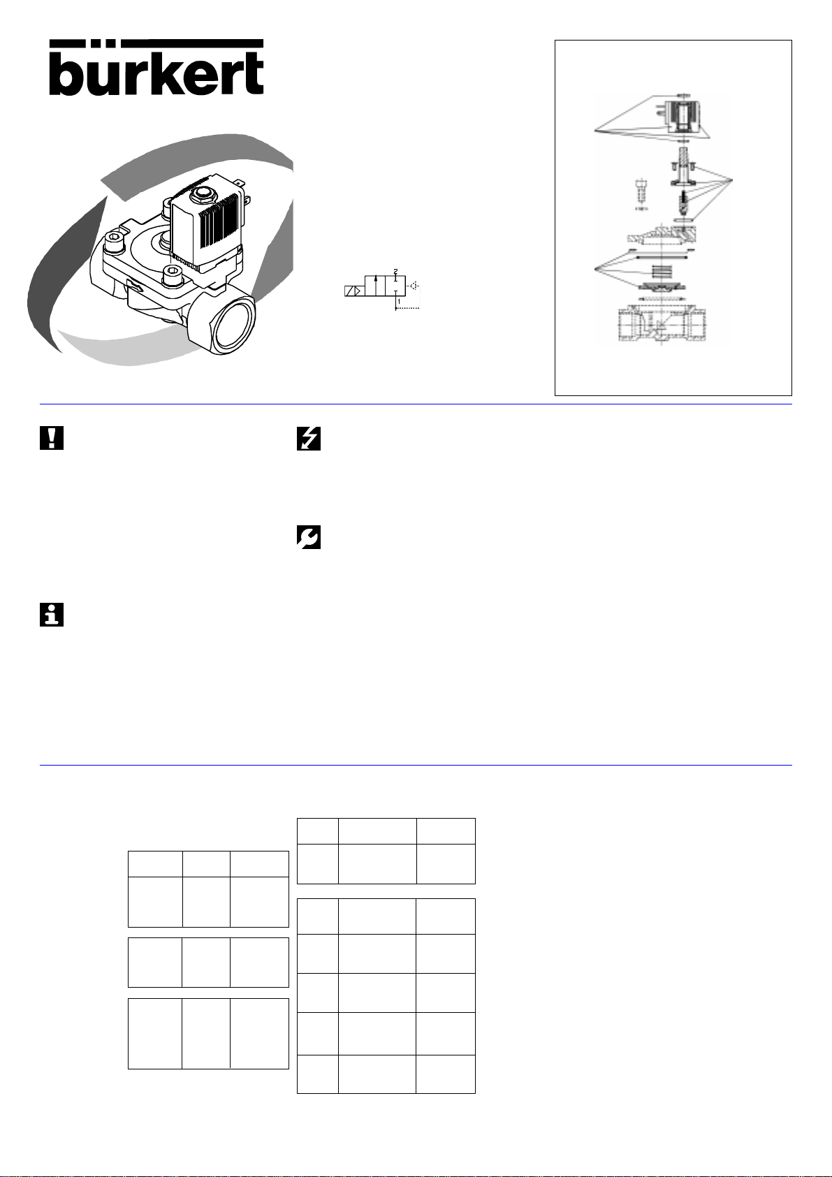
Type 5281
Betriebsanleitung / Operating instructions
Instructions de service / Manual de instrucciones
* Betriebsanleitung Seite 2
* Operating instructions page 3
* Instructions de service page 4
* Manual de instrucciones página 5
© 1999 Bürkert W erke GmbH & Co.
Alle Rechte vorbehalten.
All rights reserved.
T ous dr oits réservés.
Reservados todos los derechos.
Page 2
Fluid Control Systems
Typ 5281
LIEBER KUNDE
Herzlichen Glückwunsch zum Kauf dieses Bürkert Gerätes. Lesen
Sie bitte zu Ihrer Sicherheit diese Bedienungsanleitung vor der
Installation des Gerätes genau durch. Fr agen beant-w ortet Ihnen
gerne Ihre zuständige Bürkert-Niederlassung.
WIRKUNGSWEISE
WW A
Spulensätze
Verschleißteilsätze Ventil
Typ 5281
Verschleißteilsätze
Vorsteuerung
Betriebsanleitung
DEUTSCH
Bitte beachten Sie die Hinweise dieser Betriebsanleitung sowie
die Einsatzbedingungen und zulässigen Daten gemäß
Datenblatt Typ 5281, damit das Gerät einwandfrei funktioniert
und lange einsatzfähig bleibt:
• Halten Sie sich bei der Einsatzplanung und dem Betrieb des Gerätes
an die allgemeinen Regeln der Technik!
• T reffen Sie geeignete Maßnahmen, um unbeabsichtigtes Betätigen
oder unzulässige Beeinträchtigungen auszuschließen!
• Beachten Sie, daß in Systemen, die unter Druck stehen, Leitungen
und V entile nicht gelöst werden dürfen!
• Schalten Sie vor Eingriffen in das System in jedem Fall die Spann ung
ab!
• Bei Nichtbeachtung dieser Hinweise entfällt jegliche Haftung
unsererseits, ebenso erlischt die Garantie auf Geräte u. Zubehörteile!
• Achtung! Die Oberfläche des Elektromagneten kann bei
Dauerbetrieb sehr heiß werden. Verletzungsgefahr!
Modulares, vorgesteuertes Durchgangsventil mit
Servomembran und übergesteckter Spule
• Spule in 4 x 90° Schritten arretierbar, dazwischen um das Kernführungsrohr beliebig positionierbar
• Anzugsdrehmoment der Befestigungsschraube: max. 5 Nm
• beliebige Einbaulage, vorzugsweise mit Magnetsystem oben
• Wirkungsweise A: Arbeitsanschluß stromlos geschlossen
• Medien: Neutrale Gase und Flüssigkeiten, die Gehäuse- und
Dichtwerkstoff nicht angreifen
• Dichtwerkstoff: s. Typenschild anschließend an die Nennweite (NBR,
EPDM, FPM)
• zulässiger Temperaturbereich des Mediums: -10 °C bis 100 °C
• max. Umgebungstemperatur: +55°C
• die Gehäuseanschlüsse sind kompatibel zu den Vorgängertypen
281/291
ERSATZTEILE
Bitte geben Sie bei der Bestellung von Ersatzteilen zusätzlich zur
Bestellnummer der Ersatzteile auch die Bestellnummer Ihres
Komplettgerätes an.
Spulensätze Europa
Spulensätze N.A.F.T.A.
Spulensätze A.P.A.C.
Spannung Leistung Bestell-Nr.
[V] [W]
024 / DC 8 126 434 R
024 / 56 8 645 556 D
110 / 56 8 645 557 E
230 / 56 8 645 558 P
024 / DC 8 126 434 R
024 / 56 8 645 556 D
120 / 60 8 643 802 B
240 / 60 8 643 803 C
024 / DC 8 126 434 R
024 / 56 8 645 556 D
100 / 56 8 645 559 Q
110 / 56 8 645 557 E
200 / 56 8 645 560 M
230 / 56 8 645 558 P
T echnische Änderungen vorbehalten
Bürkert Werke GmbH Co. Alle Rechte vorbehalten
Spannung, elektrische Leistung, Druckbereich und Nennweite
entnehmen Sie dem Typenschild!
Spannungstoleranz: ±10 %
• Elektrischer Anschluß: Gerätesteckdose Typ 2508 an Anschlußsteckerfahnen der Spule (Schutzart
IP 65); Drehmoment zur Befestigung: 1Nm
• Achten Sie beim V erschr auben der Gerätestec kdose mit der Spule
auf einwandfreien Sitz der Flachdichtung!
• Achten Sie bei Impulsspulen auf asynchrones Erregen!
Eingriffe dürfen nur durch F achpersonal und mit geeignetem
Werkzeug erfolgen!
• Säubern Sie die Rohrleitungen vor der Montage des Ventils!
• Schalten Sie gegebenenfalls zum Schutz vor Störungen einen
Schmutzfänger vor!
• Beachten Sie die Durchflußrichtung (Pfeil)!
• Dichten Sie das Gewinde mit PTFE-Band ab!
• Achten Sie auf vollen Querschnitt am Ein- und Ausgang des Ventils
und auf offene Vorsteuerbohrungen!
• Verwenden Sie das Ventil auf keinen Fall als Hebel, w enn Sie die
Rohranschlüsse einschrauben!
• Vermeiden Sie Verspannungen beim Einbau des Ventilgehäuses!
• Störungen können durch Verschm utzung, K urzschluß und
Spannungsunterbrechungen entstehen.
• Achtung: Festsitz ender K ern bewirkt bei W echselspannung (A C)
Spulenüberhitzung!
• Überprüfen Sie bei Störungen Leitungsanschlüsse, Spannungen,
Stromart und Betriebsdruck!
Verschleißteilsätze
Vorsteuerung
DN Dichtwerkstoff Bestell-Nr.
13 - 65 NBR 645 561 A
13 - 65 FPM 645 562 B
13 - 65 EPDM 645 563 C
Ventil
13 NBR 624 012 J
13 FPM 624 013 K
13 EPDM 624 014 L
20 NBR 624 015 M
20 FPM 624 016 N
20 EPDM 624 017 P
25 NBR 624 018 Y
25 FPM 624 019 Z
25 EPDM 624 020 W
32, 40 NBR 624 021 K
32, 40 FPM 624 022 L
32, 40 EPDM 624 023 M
50 NBR 624 024 N
50 FPM 624 025 P
50 EPDM 624 026 Q
BÜRKERT GERMANY
Chr.-Bürkert-Straße 13-17 Berlin Ph: (0 30) 67 97 17 - 0
74653 Ingelfingen Dortmund Ph: (0 23 73) 96 81 - 0
Ph: (0 79 40) 10-0 Dresden Ph: (03 59 52) 36 30 - 0
Fax (0 79 40) 10-204 Frankfurt Ph: (0 61 03) 94 14 - 0
BÜRKERT INTERNATIONAL
A Ph. (01) 8 94 13 33 Fax (01) 8 94 13 00
AUS Ph. (02) 96 74 61 66 Fax (02) 96 74 61 67
B Ph. (03) 3 25 89 00 Fax (03) 3 25 61 61
CDN Ph. (9 05) 8 47 55 66 Fax (9 05) 8 47 90 06
CH Ph. (0 41) 7 85 66 66 Fax (0 41) 7 85 66 33
CZ Ph. (06 41) 22 61 80 Fax (06 41) 22 61 81
DK Ph. (0 44) 50 75 00 Fax (0 44) 50 75 75
E Ph. (93) 3 71 08 58 Fax (93) 3 71 77 44
ET Ph. (0 40) 54 27 38 Fax (0 40) 54 41 65
F Ph. (01) 48 10 31 10 Fax (01) 48 91 90 93
GB Ph . (0 14 53) 73 13 53 Fax (0 14 53) 73 13 43
HKG Ph. 24 80 12 02 Fax 24 18 19 45
I Ph. (02) 9 52 01 59 Fax (02) 9 52 90 33
J Ph . (03) 32 47 34 11 Fax (03) 32 47 34 72
KOR Ph. (02) 34 62 55 92 Fax (02) 34 62 55 94
N Ph. (0 63) 84 44 10 Fax (0 63) 84 44 55
MAL Ph. (04) 6 57 66 49 Fax (04) 6 57 21 06
NL Ph. (0 34) 6 59 53 11 F ax (0 34) 6 56 37 17
NZ Ph. (09) 5 70 25 39 Fax (09) 5 70 25 73
P Ph. (01) 4 42 26 08 Fax (01) 4 42 28 08
PL Ph. (0 22) 6 27 47 20 Fax (0 22) 6 27 47 20
RC Ph. (02) 27 58 31 99 Fax (02) 27 58 24 99
S Ph. (0 40) 66 45 100 Fax (08) 7 24 60 22
SF Ph. (09) 5 49 70 600 Fax (09) 5 03 12 75
SGP Ph. 3 83 26 12 Fax 3 83 26 11
TR Ph. (02 32) 4 59 53 95 Fax (02 32) 4 59 76 94
USA Ph. (9 49) 2 23 31 00 Fax (9 49) 2 23 31 98
ZA Ph. (0 11) 3 97 29 00 F ax (0 11) 3 97 44 28
Betriebsanleitung-Nr. 803 312 01/99/02
Hannover Ph: (05 11) 9 02 76 - 0
München Ph: (0 89) 82 92 28 - 0
Stuttgart Ph: (07 11) 4 51 10 - 0
Page 3

Fluid Control Systems
Type 5281
DEAR CUSTOMER
Congratulations on your purchase of this Bürkert appliance. For your
own safety, please carefully read through these operating
instructions before installing the appliance. Your local Bürkert branch
will be pleased to answer any questions you may hav e.
CIRCUIT FUNCTION
WW A
Coil Kits
Set of
Wearing
Parts Valve
Type 5281
Set of Wearing Parts
Pilot Control
Operating instructions
ENGLISH
T o ensure that the de vice will function correctly, and have a
long service life, please comply with the information in these
Operating Instructions, as well as with the application conditions and permissible data given in the Type 5281 data sheet:
• When planning the application of the device, and during its operation,
observe the general technical rules!
• T ak e suitable measures to prevent unintentional operation or
impermissible impairment!
• Note that lines and valves must not be unscrewed from systems that
are under pressure!
• Always switch off the v oltage supply bef ore w orking on the system!
• If these instructions are ignored, no liability will be accepted from our
side, and the guarantee on the device and on accessories will also
become invalid!
• Warning! The surface of the electromagnet can become very hot
during continuous operation. Danger of injury!
Modular, servo-assisted flow valve with servo-diaphragm and
push-over coil
• coil can be locked in 4 x 90° steps, in between which it can be freely
positioned around the armature guide tube
• tightening torque of the fixing screws: max. 5 Nm
• can be mounted in any position, preferably with the magnetic system
at the top
• valve operation A: service port normally closed
• media: neutral fluids and gases which do not attack the valv e body
and seal or diaphragm materials
• seal material: refer to rating plate f ollo wing the nominal diameter
(NBR, EPDM, FPM)
• permissible temperature range of the medium: -10 °C to 100 °C
• max. ambient temperature: + 55°
• the port connections are compatible with the previous model 281/291
We reserve the right to make technical changes without
notice
Bürkert Werke GmbH Co. All rights reserved
Read the voltage, electrical power, type of protection and
current from the rating plate!
Voltage tolerance: ±10%
• Electrical power connection: Instrument socket type 2508 to the tag
connections on the coil (protection class IP 65);
Tightening torque: 1 Nm
• When screwing down the instrument socket onto the coil, ensure that
the flat seal is well seated!
• With impulse coils, pay attention to asynchronous excitation!
Work on the valve should only be carried out by specialist staff
and with the correct tools!
• Clean the piping system before installing the valve!
• Where necessary, connect a strainer upstream to protect against
faults!
• Pay attention to the flow direction (direction of arro w).
• Seal the thread using PTFE tape!
• Ensure that there is the full diameter available at the inlets and outlets
to the valve, and that pilot channels are open!
• When tightening the pipe connections, never use the valv e as a le v er!
• Be careful of distortion when installing the valve body.
• Faults can be caused by soiling, short circuits and loss of power!
• Attention: Jammed coils can cause coil overheating with A C !
• In case of faults, check the port connections, voltages, type of current
and operational pressure!
SPARE PARTS
When ordering replacements parts, please also quote the order
number of your complete appliance in addition to the order
number of the replacement parts.
Coil kits Europe
Coil kits N.A.F.T.A.
Coil kits A.P .A.C.
Voltage Power Order no.
[V] [W]
024 / DC 8 126 434 R
024 / 56 8 645 556 D
110 / 56 8 645 557 E
230 / 56 8 645 558 P
024 / DC 8 126 434 R
024 / 56 8 645 556 D
120 / 60 8 643 802 B
240 / 60 8 643 803 C
024 / DC 8 126 434 R
024 / 56 8 645 556 D
100 / 56 8 645 559 Q
110 / 56 8 645 557 E
200 / 56 8 645 560 M
230 / 56 8 645 558 P
Set of W earing P arts
Pilot Control
DN Sealing material Order no.
13 - 65 NBR 645 561 A
13 - 65 FPM 645 562 B
13 - 65 EPDM 645 563 C
Valve
13 NBR 624 012 J
13 FPM 624 013 K
13 EPDM 624 014 L
20 NBR 624 015 M
20 FPM 624 016 N
20 EPDM 624 017 P
25 NBR 624 018 Y
25 FPM 624 019 Z
25 EPDM 624 020 W
32, 40 NBR 624 021 K
32, 40 FPM 624 022 L
32, 40 EPDM 624 023 M
50 NBR 624 024 N
50 FPM 624 025 P
50 EPDM 624 026 Q
BÜRKERT GERMANY
Chr.-Bürkert-Straße 13-17 Berlin Ph: (0 30) 67 97 17 - 0
74653 Ingelfingen Dortmund Ph: (0 23 73) 96 81 - 0
Ph: (0 79 40) 10-0 Dresden Ph: (03 59 52) 36 30 - 0
Fax (0 79 40) 10-204 Frankfurt Ph: (0 61 03) 94 14 - 0
BÜRKERT INTERNATIONAL
A Ph. (01) 8 94 13 33 Fax (01) 8 94 13 00
AUS Ph. (02) 96 74 61 66 Fax (02) 96 74 61 67
B Ph. (03) 3 25 89 00 Fax (03) 3 25 61 61
CDN Ph. (9 05) 8 47 55 66 Fax (9 05) 8 47 90 06
CH Ph. (0 41) 7 85 66 66 Fax (0 41) 7 85 66 33
CZ Ph. (06 41) 22 61 80 Fax (06 41) 22 61 81
DK Ph. (0 44) 50 75 00 Fax (0 44) 50 75 75
E Ph. (93) 3 71 08 58 Fax (93) 3 71 77 44
ET Ph. (0 40) 54 27 38 Fax (0 40) 54 41 65
F Ph. (01) 48 10 31 10 Fax (01) 48 91 90 93
GB Ph . (0 14 53) 73 13 53 Fax (0 14 53) 73 13 43
HKG Ph. 24 80 12 02 Fax 24 18 19 45
I Ph. (02) 9 52 01 59 Fax (02) 9 52 90 33
J Ph . (03) 32 47 34 11 Fax (03) 32 47 34 72
KOR Ph. (02) 34 62 55 92 Fax (02) 34 62 55 94
N Ph. (0 63) 84 44 10 Fax (0 63) 84 44 55
MAL Ph. (04) 6 57 66 49 Fax (04) 6 57 21 06
NL Ph. (0 34) 6 59 53 11 F ax (0 34) 6 56 37 17
NZ Ph. (09) 5 70 25 39 Fax (09) 5 70 25 73
P Ph. (01) 4 42 26 08 Fax (01) 4 42 28 08
PL Ph. (0 22) 6 27 47 20 Fax (0 22) 6 27 47 20
RC Ph. (02) 27 58 31 99 Fax (02) 27 58 24 99
S Ph. (0 40) 66 45 100 Fax (08) 7 24 60 22
SF Ph. (09) 5 49 70 600 Fax (09) 5 03 12 75
SGP Ph. 3 83 26 12 Fax 3 83 26 11
TR Ph. (02 32) 4 59 53 95 Fax (02 32) 4 59 76 94
USA Ph. (9 49) 2 23 31 00 Fax (9 49) 2 23 31 98
ZA Ph. (0 11) 3 97 29 00 F ax (0 11) 3 97 44 28
Operating Instructions No. 803 312 01/99/02
Hannover Ph: (05 11) 9 02 76 - 0
München Ph: (0 89) 82 92 28 - 0
Stuttgart Ph: (07 11) 4 51 10 - 0
Page 4

Fluid Control Systems
Type 5281
CHER CLIENT
Nos compliments chaleureux pour l’achat de cet appareil Bürkert.
Lisez attentivement cette notice de service pour votre sécurité avant
de procéder à l’installation de l’appareil. La succursale Bürkert
compétente pour vous est là pour répondre à vos questions.
FONCTIONNEMENT
WW A
Jeu de
bobines
Jeu de pièces
d'usure
vanne
Type 5281
Jeu de pièces
d'usure
vanne de pilote
Instructions de service
FRANÇAIS
Nous vous prions d’observer les indications de ces instructions
de service ainsi que les conditions d’utilisation et les données
admissibles selon la fiche technique du type 5281, afin que
l’appareil fonctionne parfaitement et reste longtemps en parfait
état d’utilisation:
• Respectez les règles reconnues de la technique pour le plan
d’utilisation et le fonctionnement de l’appareil!
• Prenez les mesures appropriées afin d’exclure une action
intempestive ou une atteinte inadmissible!
• Observer que les conduites et les vannes des systèmes se trouvant
sous pression ne doivent pas être démontées!
• Déclenchez dans tous es cas la tension électrique avant toute
intervention dans le système!
• Nous déclinons toute responsabilité et la garantie sur l’appareil et les
accessoires expire, en cas de non respect de ces instructions de
même que d’intervention non autorisée sur l’appareil.
• Attention! La surface des électroaimants peut devenir très
chaude en régime continu. Risque de blessure!
Vanne droite magnétique modulaire pilotée, a v ec membrane
de pilotage et bobine embrochée au-dessus
• la bobine peut être bloquée par pas de 4 x 90°, et peut être
positionnée entre ces points à volonté autour du tube de guidage du
noyau
• couple de serrage des vis de fixation: max. 5 Nm
• position de montage quelconque, de préférence avec système
magnétique en haut
• mode de fonctionnement A: raccord de trav ail f ermé en l’absence de
courant
• fluides: liquides et gaz neutres qui n’attaquent pas les matières du
corps, des joints et de la membrane
• matière du joint: voir sur plaquette signalétique à la suite du diamètre
nominal (NBR; EPDM, FPM)
PIÈCES DE RECHANGE
Lors de la commande de pièces de rechange, indiquez, en plus de
leur numéro de commande, celui de commande de votre appareil
complet.
Jeu de bobines
Europa/Europe
Jeu de bobines
N.A.F.T.A.
Jeu de bobines
A.P.A.C.
T ension Puissance No commande
[V] [W]
024 / DC 8 126 434 R
024 / 56 8 645 556 D
110 / 56 8 645 557 E
230 / 56 8 645 558 P
024 / DC 8 126 434 R
024 / 56 8 645 556 D
120 / 60 8 643 802 B
240 / 60 8 643 803 C
024 / DC 8 126 434 R
024 / 56 8 645 556 D
100 / 56 8 645 559 Q
110 / 56 8 645 557 E
200 / 56 8 645 560 M
230 / 56 8 645 558 P
Sous resérve de modification techniques.
Bürkert Werke GmbH Co. Tous droits réservés.
• plage de température admissible du fluide: -10 à +100°
• température ambiante admissible: +55°
• les raccords du corps sont compatibles avec les types 281/291
précédents
Lisez sur la plaquette signalétique la tension, la puissance
électrique, la plage de pression et le diamètre nominal!
T olérance de tension: ±10%
• Raccordement électrique: prise d’appareil type 2508 sur les
fiches de raccordement de la bobine (mode de protection IP 65);
couple de serrage de la fixation: 1 Nm
• Veiller en vissant la prise d’appareil avec la bobine à une
application parfaite du joint plat!
• Veiller à une excitation asynchrone sur les bobines à impulsions!
Des interventions ne doivent être effectuées que par un
personnel qualifié équipé de l’outillage approprié!
• Nettoyer les conduites avant le montage de la v anne!
• Monter éventuellement un filtre en amont pour prévenir des
dérangements!
• Observer le sens d’écoulement (flèche)!
• Veiller à garder la pleine section à l’entrée et à la sortie de la vanne et
aux perçages de pilotage ouverts!
• N’utiliser en aucun cas la bobine comme levier lors du vissage des
raccords!
• Eviter des déformations lors du montage du corps de vanne!
• Des dérangements peuvent provenir de la saleté, de courts-circuits et
d’interruptions de tension.
• Attention: un noy au bloqué prov oque en cas d’alimentation en tension
alternative (AC) une surchauffe de la bobine.
• Vérifier en cas de dérangement les raccords des conduites, les
tensions, le genre de courant et la pression de service!
Jeu de pièces d'usure
Vanne de pilote
DN Matière de joint No commande
13 - 65 NBR 645 561 A
13 - 65 FPM 645 562 B
13 - 65 EPDM 645 563 C
Vanne
13 NBR 624 012 J
13 FPM 624 013 K
13 EPDM 624 014 L
20 NBR 624 015 M
20 FPM 624 016 N
20 EPDM 624 017 P
25 NBR 624 018 Y
25 FPM 624 019 Z
25 EPDM 624 020 W
32, 40 NBR 624 021 K
32, 40 FPM 624 022 L
32, 40 EPDM 624 023 M
50 NBR 624 024 N
50 FPM 624 025 P
50 EPDM 624 026 Q
BÜRKERT GERMANY
Chr.-Bürkert-Straße 13-17 Berlin Ph: (0 30) 67 97 17 - 0
74653 Ingelfingen Dortmund Ph: (0 23 73) 96 81 - 0
Ph: (0 79 40) 10-0 Dresden Ph: (03 59 52) 36 30 - 0
Fax (0 79 40) 10-204 Frankfurt Ph: (0 61 03) 94 14 - 0
BÜRKERT INTERNATIONAL
A Ph. (01) 8 94 13 33 Fax (01) 8 94 13 00
AUS Ph. (02) 96 74 61 66 Fax (02) 96 74 61 67
B Ph. (03) 3 25 89 00 Fax (03) 3 25 61 61
CDN Ph. (9 05) 8 47 55 66 Fax (9 05) 8 47 90 06
CH Ph. (0 41) 7 85 66 66 Fax (0 41) 7 85 66 33
CZ Ph. (06 41) 22 61 80 Fax (06 41) 22 61 81
DK Ph. (0 44) 50 75 00 Fax (0 44) 50 75 75
E Ph. (93) 3 71 08 58 Fax (93) 3 71 77 44
ET Ph. (0 40) 54 27 38 Fax (0 40) 54 41 65
F Ph. (01) 48 10 31 10 Fax (01) 48 91 90 93
GB Ph . (0 14 53) 73 13 53 Fax (0 14 53) 73 13 43
HKG Ph. 24 80 12 02 Fax 24 18 19 45
I Ph. (02) 9 52 01 59 Fax (02) 9 52 90 33
J Ph . (03) 32 47 34 11 Fax (03) 32 47 34 72
KOR Ph. (02) 34 62 55 92 Fax (02) 34 62 55 94
N Ph. (0 63) 84 44 10 Fax (0 63) 84 44 55
MAL Ph. (04) 6 57 66 49 Fax (04) 6 57 21 06
NL Ph. (0 34) 6 59 53 11 F ax (0 34) 6 56 37 17
NZ Ph. (09) 5 70 25 39 Fax (09) 5 70 25 73
P Ph. (01) 4 42 26 08 Fax (01) 4 42 28 08
PL Ph. (0 22) 6 27 47 20 Fax (0 22) 6 27 47 20
RC Ph. (02) 27 58 31 99 Fax (02) 27 58 24 99
S Ph. (0 40) 66 45 100 Fax (08) 7 24 60 22
SF Ph. (09) 5 49 70 600 Fax (09) 5 03 12 75
SGP Ph. 3 83 26 12 Fax 3 83 26 11
TR Ph. (02 32) 4 59 53 95 Fax (02 32) 4 59 76 94
USA Ph. (9 49) 2 23 31 00 Fax (9 49) 2 23 31 98
ZA Ph. (0 11) 3 97 29 00 F ax (0 11) 3 97 44 28
Instructions de service no. 803 312 01/99/02
Hannover Ph: (05 11) 9 02 76 - 0
München Ph: (0 89) 82 92 28 - 0
Stuttgart Ph: (07 11) 4 51 10 - 0
Page 5

Fluid Control Systems
Tipo 5281
QUERIDO CLIENTE
Enhorabuena por la compra de este aparato Bürkert! Antes de la
instalación del aparato y por su propia seguridad, lea atentamente
estas Instrucciones de servicio. El establecimiento competente
Bürkert más próximo le aclarará gustosamente toda clase de
prequentas al respecto.
Juego
de bobina
Tipo 5281
Juego del piazas
de cierre
válvula de mando
previo
Manual de instrucciones
ESP AÑOL
Se ruega observar las indicaciones contenidas en estas
instrucciones de servicio así como las condiciones de uso y
datos admisibles con arreglo a la hoja de datos Tipo 5281, de
modo que el aparato funcione impecablemente y permanezca
durante largo tiempo apto para el empleo:
• Para la planificación y operación del aparato, atenerse a las reglas
generales de la técnica!
• T omar las medidas apropiadas para excluir acciona-miento no
intencionados o perjuicios inadmisibles!
• Prestar atención a que en sistemas que se encuentran bajo presión
no deben desconectarse conducciones y válvulas!
• Antes de proceder a intervenciones en el sistema, desconectar
siempre la tensión!
• La inobservancia de estas indicaciones así como las interven-ciones
inadmisibles en el aparato supone la declinción por nuestra parte de
toda clase de responsabilidad, extinguiéndose asimismo la garantia
de los aparatos y piezas de accesorios.
• Atención: la superficie de los electromagnetos puede calen-
tarse mucho con funcionamiento de régimen continuo. Peligro
de quemaduras!
Válvula de paso modular y de mando previo con
servomembrana y bobina sobreenchufada
• la bobina es bloqueable en pasos 4 x 90°, en el medio y al-rededor
del tubo-guía de macho es posicionable a discreción
• par de apriete del tornillo de fijación: máx. 5 Nm
• posición de montaje a discreción, preferiblemente con sistema de
imanes arriba
• funcionamiento A: conexión de trabajo cerrada sin corriente
• medios: gases neutros y líquidos que no atacan a los materiales de
carcasa y de estanqueidad
• material de estanqueidad: véase la placa indicadora de Tipo contigua
a la anchura nominal (NBR, EPDM, FPM)
PIAZAS DE RERECAMBIO
Con ocasión del pedido de las pieza de repuesto, rogamos indicar
además del número de pedido de la pieza de requesto también el
número de pedido de su aparato completo.
Juego de bobina
Europa/Europe
Juego de bobina
N.A.F.T.A.
Juego de bobina
A.P.A.C.
T ensión Potencia No de pedito
[V] [W]
024 / DC 8 126 434 R
024 / 56 8 645 556 D
110 / 56 8 645 557 E
230 / 56 8 645 558 P
024 / DC 8 126 434 R
024 / 56 8 645 556 D
120 / 60 8 643 802 B
240 / 60 8 643 803 C
024 / DC 8 126 434 R
024 / 56 8 645 556 D
100 / 56 8 645 559 Q
110 / 56 8 645 557 E
200 / 56 8 645 560 M
230 / 56 8 645 558 P
FUNCIONAMIENTO
WW A
Nos reservamos el derecho de llevar a cabo modificaciones tècnicas
sin previo aviso.
Bürkert Werke GmbH Co. Reservados todos los derechos.
• máxima temperatura ambiente: +55 °C
• gama admisible de temperatura del medio: -10°C a 100°C
• las conexiones de carcasa son compatibles con los Tipos
precedentes 281/291
T ensión, potencia eléctrica, gama de presión y anchura
nominal se deducen de la placa indicadora de Tipo
T olerancia de tensión: ±10 %
• Conexión eléctrica: enchufe eléctrico del aparato Tipo 2508 a la
etiqueta colgante de la bobina (clase de protección IP 65); par de
apriete para la fijación: 1Nm
• Al atornillar el enchufe eléctrico del aparato con la bobina, poner
cuidado en que la empaquetadura plana asiente impecable-mente!
• En caso de bobinas de impulso, prestar atención a la excitación
asincrónica!
Las intervenciones solamente deben ser llevadas a cabo por
personal especialista y con las herramientas adecuadas!
• Antes del montaje de la válvula, limpiar las tuberías!
• Para protección contra averías, preconectar dado el caso un colector
de lodo!
• T ener en cuenta la dirección de paso (flecha)!
• T ener en cuenta la sección transv ersal completa en la entr ada y
salida de la válvula y los taladros abiertos del control piloto!
• No utilizar en caso alguno la válvula como palanca cuando se
atornillan canalizaciones de aire!
• Evitar las deformaciones durante el montaje de la carcasa de válvula!
• Las averías pueden originarse por contaminación, cortocircuito o
interrupción de tensión!
• Atención: con tensión alterna (AC), el macho de asiento duro provoca
sobrecalentamiento de la bobina!
• En caso de avería, verificar las conexiones de líneas, tensiones ,
clase de corriente y presión de operación!
Juego del piazas de cierre
Válvula de mando previo
DN Material de No de pedito
estanqueidad
13 - 65 NBR 645 561 A
13 - 65 FPM 645 562 B
13 - 65 EPDM 645 563 C
Válvula
13 NBR 624 012 J
13 FPM 624 013 K
13 EPDM 624 014 L
20 NBR 624 015 M
20 FPM 624 016 N
20 EPDM 624 017 P
25 NBR 624 018 Y
25 FPM 624 019 Z
25 EPDM 624 020 W
32, 40 NBR 624 021 K
32, 40 FPM 624 022 L
32, 40 EPDM 624 023 M
50 NBR 624 024 N
50 FPM 624 025 P
50 EPDM 624 026 Q
Juego del piazas
de cierre
válvula
BÜRKERT GERMANY
Chr.-Bürkert-Straße 13-17 Berlin Ph: (0 30) 67 97 17 - 0
74653 Ingelfingen Dortmund Ph: (0 23 73) 96 81 - 0
Ph: (0 79 40) 10-0 Dresden Ph: (03 59 52) 36 30 - 0
Fax (0 79 40) 10-204 Frankfurt Ph: (0 61 03) 94 14 - 0
BÜRKERT INTERNATIONAL
A Ph. (01) 8 94 13 33 Fax (01) 8 94 13 00
AUS Ph. (02) 96 74 61 66 Fax (02) 96 74 61 67
B Ph. (03) 3 25 89 00 Fax (03) 3 25 61 61
CDN Ph. (9 05) 8 47 55 66 Fax (9 05) 8 47 90 06
CH Ph. (0 41) 7 85 66 66 Fax (0 41) 7 85 66 33
CZ Ph. (06 41) 22 61 80 Fax (06 41) 22 61 81
DK Ph. (0 44) 50 75 00 Fax (0 44) 50 75 75
E Ph. (93) 3 71 08 58 Fax (93) 3 71 77 44
ET Ph. (0 40) 54 27 38 Fax (0 40) 54 41 65
F Ph. (01) 48 10 31 10 Fax (01) 48 91 90 93
GB Ph . (0 14 53) 73 13 53 Fax (0 14 53) 73 13 43
HKG Ph. 24 80 12 02 Fax 24 18 19 45
I Ph. (02) 9 52 01 59 Fax (02) 9 52 90 33
J Ph . (03) 32 47 34 11 Fax (03) 32 47 34 72
KOR Ph. (02) 34 62 55 92 Fax (02) 34 62 55 94
N Ph. (0 63) 84 44 10 Fax (0 63) 84 44 55
MAL Ph. (04) 6 57 66 49 Fax (04) 6 57 21 06
NL Ph. (0 34) 6 59 53 11 F ax (0 34) 6 56 37 17
NZ Ph. (09) 5 70 25 39 Fax (09) 5 70 25 73
P Ph. (01) 4 42 26 08 Fax (01) 4 42 28 08
PL Ph. (0 22) 6 27 47 20 Fax (0 22) 6 27 47 20
RC Ph. (02) 27 58 31 99 Fax (02) 27 58 24 99
S Ph. (0 40) 66 45 100 Fax (08) 7 24 60 22
SF Ph. (09) 5 49 70 600 Fax (09) 5 03 12 75
SGP Ph. 3 83 26 12 Fax 3 83 26 11
TR Ph. (02 32) 4 59 53 95 Fax (02 32) 4 59 76 94
USA Ph. (9 49) 2 23 31 00 Fax (9 49) 2 23 31 98
ZA Ph. (0 11) 3 97 29 00 F ax (0 11) 3 97 44 28
Manual de instrucciones no 803 312 01/99/02
Hannover Ph: (05 11) 9 02 76 - 0
München Ph: (0 89) 82 92 28 - 0
Stuttgart Ph: (07 11) 4 51 10 - 0
 Loading...