

Burkert 3364, 3363, 3365 Operating Instructions Manual
Operating Instructions
Type 3363, 3364, 3365
Electromotive diaphragm control valve

We reserve the right to make technical changes without notice.
Technische Änderungen vorbehalten.
Sous réserve de modifications techniques.
© Bürkert Werke GmbH & Co. KG, 2016 – 2018
Operating Instructions 1810/02_EUen_00810537 / Original DE
Type 3363, 3364, 3365
english
Electromotive diaphragm control valve
Contents
1 THE OPERATING INSTRUCTIONS .............................................................................................................................................7
1.1 Symbols
Definition of the term “device” ........................................................................................................................................7
1.2
INTENDED USE ....................................................................................................................................................................................8
2
BASIC SAFETY INSTRUCTIONS .................................................................................................................................................9
3
GENERAL INFORMATION .............................................................................................................................................................11
4
Contact address ..................................................................................................................................................................11
4.1
4.2 Warranty
Information on the Internet ............................................................................................................................................ 11
4.3
PRODUCT DESCRIPTION ............................................................................................................................................................12
5
General description ...........................................................................................................................................................12
5.1
Properties ..............................................................................................................................................................................12
5.2
5.3 Variants
......................................................................................................................................................................................7
...................................................................................................................................................................................11
..................................................................................................................................................................................... 13
STRUCTURE AND FUNCTION ...................................................................................................................................................14
6
Diagram – structure of the electromotive diaphragm control valve .......................................................14
6.1
Valve position after failure of the supply voltage ..............................................................................................15
6.2
Safety position ......................................................................................................................................................................15
6.3
Display of the device state ...........................................................................................................................................16
6.4
Factory settings ..................................................................................................................................................................18
6.5
ELECTRICAL CONTROL ................................................................................................................................................................19
7
Function diagram of the electromotive diaphragm control valve .............................................................20
7.1
Operating mode of the electrical control .............................................................................................................21
7.2
SAFEPOS energy-pack (option) .................................................................................................................................24
7.3
TECHNICAL DATA .............................................................................................................................................................................26
8
8.1 Conformity
8.2 Standards
..............................................................................................................................................................................26
................................................................................................................................................................................26
3

Type 3363, 3364, 3365
english
8.3 Licenses ...................................................................................................................................................................................26
Type label ................................................................................................................................................................................27
8.4
Labeling of the forged bodies ......................................................................................................................................27
8.5
Labeling of the tube valve bodies (VP) ...................................................................................................................28
8.6
Operating conditions ........................................................................................................................................................29
8.7
General technical data .....................................................................................................................................................32
8.8
Electrical data .......................................................................................................................................................................32
8.9
Flow characteristic .............................................................................................................................................................35
8.10
Flow values for forged bodies .....................................................................................................................................35
8.11
Flow values for cast bodies and plastic bodies .................................................................................................38
8.12
Flow values for tube valve bodies .............................................................................................................................40
8.13
INSTALLATION OF THE VALVE .................................................................................................................................................43
9
Safety instructions .............................................................................................................................................................43
9.1
Installation position of the diaphragm control valves .....................................................................................43
9.2
Installation of devices with socket connection, flanged connection, clamp connection or bond
9.3
connection ..................................................................................................................................................................................................45
Installation of devices with welded connection .................................................................................................46
9.4
Rotating the actuator ........................................................................................................................................................52
9.5
Holding device ......................................................................................................................................................................53
9.6
ELECTRICAL INSTALLATION ......................................................................................................................................................54
10
Electrical installation with circular plug-in connector ............................................................................................ 54
10.1
Electrical installation with cable gland ....................................................................................................................58
10.2
11 START-UP
11.1
.............................................................................................................................................................................................64
Safety instructions .............................................................................................................................................................64
Setting options for start-up ...........................................................................................................................................64
11.2
Base settings ........................................................................................................................................................................64
11.3
Setting safety position .....................................................................................................................................................66
11.4
11.5 A
11.6 S
11.7
4
djust the position control – running M.Q0.TUNE ......................................... 67
et standard signal for set-point position ........................................................ 70
Select physical unit for process control .................................................................................................................71

Type 3363, 3364, 3365
english
11.8 Parameterize process values .......................................................................................................................................72
Scaling process control ...................................................................................................................................................73
11.9
Setting dead band of the process control.............................................................................................................74
11.10
Set up process control – run P.LIN, P.TUNE ........................................................................................................75
11.11
Set operating state AUTOMATIC ................................................................................................................................77
11.12
12 OPERATION
Overview: Availability of the control elements ....................................................................................................78
12.1
Display elements ...................................................................................................................................................................................79
12.2
Control elements .................................................................................................................................................................81
12.3
büS Service interface .......................................................................................................................................................82
12.4
Accepting and saving SIM card data (option)..................................................................................................................... 83
12.5
DISPLAY OPERATION (OPTION) ..............................................................................................................................................84
13
User interface .......................................................................................................................................................................84
13.1
Description of the keys ....................................................................................................................................................84
13.2
Display views ......................................................................................................................................................................... 85
13.3
Description of the symbols ...........................................................................................................................................88
13.4
13.5 U
Screen saver ..........................................................................................................................................................................92
13.6
.........................................................................................................................................................................................78
ser rights and password protection ................................................................. 90
BASIC FUNCTIONS .........................................................................................................................................................................93
14
Switching operating state, AUTOMATIC – MANUAL ........................................................................................93
14.1
Activating – deactivating the sealing function ....................................................................................................95
14.2
Activating – deactivating correction characteristic ..........................................................................................97
14.3
Changing effective direction ......................................................................................................................................100
14.4
Deactivating process control .....................................................................................................................................102
14.5
MANUAL ACTUATION OF THE VALVE ............................................................................................................................... 103
15
Actuating valve electrically ......................................................................................................................................... 103
15.1
Actuating valve mechanically .................................................................................................................................... 105
15.2
EXTENDED FUNCTIONS ........................................................................................................................................................... 107
16
5
Type 3363, 3364, 3365
english
17 OPERATING STRUCTURE / FACTORY SETTINGS ......................................................................................................108
Operating structure of the configuration area ................................................................................................. 108
17.1
Context menu for operation on the display .......................................................................................................127
17.2
FIELDBUS GATEWAY ...................................................................................................................................................................129
18
Technical data .................................................................................................................................................................... 129
18.1
Industrial Ethernet ...........................................................................................................................................................129
18.2
Electrical connection ......................................................................................................................................................130
18.3
Access to the büS Service interface ..................................................................................................................... 132
18.4
Web server ...........................................................................................................................................................................132
18.5
Configuration and parameterization of EtherNet/IP .....................................................................................136
18.6
Object route function .....................................................................................................................................................136
18.7
18.8 Objects
MAINTENANCE, TROUBLESHOOTING ..............................................................................................................................140
19
Visual inspection .............................................................................................................................................................. 140
19.1
Replacing the diaphragm ............................................................................................................................................ 140
19.2
Replacing the SAFEPOS energy pack ..................................................................................................................145
19.3
Maintenance messanges .............................................................................................................................................145
19.4
19.5 Troubleshooting
20 CLEANING
Flushing the valve body ................................................................................................................................................149
20.1
ACCESSORIES, SPARE PARTS ............................................................................................................................................. 150
21
Communications software .......................................................................................................................................... 151
21.1
Spare parts ..........................................................................................................................................................................151
21.2
.................................................................................................................................................................................. 139
................................................................................................................................................................145
......................................................................................................................................................................................... 149
22 DISASSEMBLY
Safety instructions .......................................................................................................................................................... 152
22.1
PACKAGING, TRANSPORT .......................................................................................................................................................153
23
24 STORAGE
25 DISPOSAL
6
................................................................................................................................................................................ 152
...........................................................................................................................................................................................153
......................................................................................................................................................................................... 154
Type 3363, 3364, 3365
english
The operating instructions
1 THE OPERATING INSTRUCTIONS
The operating instructions describe the entire life cycle of the device. Keep these instructions in a location which is
easily accessible to every user and make these instructions available to every new owner of the device.
Important safety information.
Read the operating instructions carefully and thoroughly. Study in particular the chapters entitled Basic safety
instructions and Intended use.
▶ The operating instructions must be read and understood.
1.1 Symbols
DANGER!
Warns of an immediate danger!
▶ Failure to observe the warning will result in fatal or serious injuries.
WARNING!
Warns of a potentially dangerous situation!
▶ Failure to observe the warning may result in serious injuries or death.
CAUTION!
Warns of a possible danger!
▶ Failure to observe this warning may result in a moderate or minor injury.
ATTENTION!
Warns of damage to property!
• Failure to observe the warning may result in damage to the device or other equipment.
Indicates important additional information, tips and recommendations.
Refers to information in these operating instructions or in other documentation.
▶ designates an instruction which you must follow to prevent a hazard.
→ designates a procedure which you must carry out.
indicates a result.
1.2 Definition of the term “device”
• Device: The term “device” used in these instructions applies to the electromotive diaphragm control valve of
Types 3363, 3364 and 3365.
• Ex: In these instructions, the abbreviation “Ex” stands for “explosion-risk”.
7

Type 3363, 3364, 3365
english
Intended use
2 INTENDED USE
Non-authorized use of the electromotive diaphragm control valve Type 3363, 3364 and 3365 may be a
hazard to people, nearby equipment and the environment.
The electromotive diaphragm control valve Type 3363, 3364 and 3365 is designed to control the flow of
liquid and gaseous media.
▶ Standard devices must not be used in the potentially explosive area. They do not have a separate Ex rating
plate which indicates approval for the explosion-proof area.
▶ The surfaces of the device must not be cleaned with alkaline cleaning agents.
▶ If the valve position is relevant as regards safety in the event of a power failure: Use only those devices which
have the SAFEPOS energy-pack (optional energy pack).
▶ Use according to the authorized data, operating conditions, and conditions of use specified in the contract
documents and operating instructions.
▶ Protect the device against harmful environmental influences (e.g. radiation, air humidity, vapors, etc.)! If in
doubt, consult the relevant sales company.
Use the device
▶ only in conjunction with third-party devices and components recommended and authorized by Bürkert.
▶ only when in perfect condition and always ensure proper storage, transportation, installation and operation.
▶ only as intended.
8

Type 3363, 3364, 3365
english
Basic safety instructions
3 BASIC SAFETY INSTRUCTIONS
These safety instructions do not consider any contingencies or incidents which occur during installation, operation
and maintenance. The operator is responsible for observing the location-specific safety regulations, also with reference to the personnel.
Risk of injury from high pressure!
▶ Before working on the system or device, switch off the pressure and vent or drain lines.
Danger of burns and risk of fire.
Following an extended duty cycle or as a result of a hot medium, the surface of the device may become hot.
▶ Only touch the device when wearing protective gloves.
▶ Keep the device away from highly flammable substances and media.
Risk of crushing due to mechanically moving parts.
▶ Perform installation work on the pressure piece, diaphragm and valve body only when they have been isolated
from the power supply.
Devices with SAFEPOS energy-pack: Completely drain SAFEPOS energy-pack. Wait until LED illuminated ring
goes out; the LED status must not be in LED off mode.
▶ Keep clear of the openings in the valve body.
Danger due to an uncontrolled process in the event of a power failure.
If devices do not have the optional SAFEPOS energy-pack, the valve remains in an undefined position in the event of
a power failure.
▶ If the valve position is relevant as regards safety in the event of a power failure: Use only those devices which
have the SAFEPOS energy-pack (optional energy pack).
▶ In the SAFEPOS select a valve position which is safe for the process.
Danger due to loud noises.
▶ Depending on the operating conditions, the device may generate loud noises. More detailed information on the like-
lihood of loud noises is available from the relevant sales office.
▶ Wear hearing protection when in the vicinity of the device.
Leaking medium when the diaphragm is worn.
▶ Regularly check relief bore for leaking medium.
▶ If medium is leaking out of the relief bore, change the diaphragm.
▶ If the media is hazardous, protect the area surrounding the discharge point against dangers.
General hazardous situations.
To prevent injuries:
▶ In a hazardous area, the device may be used only in accordance with the specification on the separate Ex type
label.
▶ To use the device in an explosion-risk area, observe the additional information with safety instructions for the
explosion-risk area enclosed with the device or the separate explosion-risk operating instructions.
9
Type 3363, 3364, 3365
english
Basic safety instructions
▶ Devices without a separate Ex rating plate may not be used in a potentially explosive area.
▶ Only feed in the media types specified in chapter “8 Technical data” to the media connections.
▶ Do not make any internal or external changes on the device and do not subject it to mechanical stress.
▶ Secure the system from unintentional actuation.
▶ Only trained technicians may perform installation and maintenance work.
▶ Transport, install and dismantle a heavy device with the help of another person and with appropriate tools.
▶ After an interruption, ensure that the process is restarted in a controlled manner. Observe sequence!
1. Apply supply voltage.
2. Charge the device with medium.
▶ Observe the general rules of technology.
▶ The valves must be installed in accordance with the regulations applicable in the country.
ATTENTION!
Electrostatic sensitive components and modules.
The device contains electronic components which react sensitively to electrostatic discharge (ESD). Contact with
electrostatically charged persons or objects are hazardous to these components. In the worst case scenario, they
will be destroyed immediately or will fail after start-up.
• Observe the requirements in accordance with EN 61340-5-1 to minimize or avoid the possibility of damage
caused by sudden electrostatic discharge!
• Do not touch electronic components while the supply voltage is switched on!
10

Type 3363, 3364, 3365
english
General information
4 GENERAL INFORMATION
4.1 Contact address
Germany
Bürkert Fluid Control Systems
Sales Center
Christian-Bürkert-Str. 13-17
D-74653 Ingelfingen
Tel. + 49 (0) 7940 - 10 91 111
Fax + 49 (0) 7940 - 10 91 448
Email: info@burkert.com
International
Contact addresses can be found on the final pages of the printed operating instructions.
And also on the Internet at:
www.burkert.com
4.2 Warranty
The warranty is only valid if the device is used as intended in accordance with the specified application conditions.
4.3 Information on the Internet
Operating instructions and data sheets for Types 3363, 3364 and 3365 can be found on the Internet at:
www.burkert.com.
11

Type 3363, 3364, 3365
english
Product description
5 PRODUCT DESCRIPTION
5.1 General description
The electromotive diaphragm control valve Type 3363, 3364 and 3365 is suitable for controlling the flow rate of
liquid and gaseous media. These may be neutral, high-purity, sterile, contaminated, aggressive or abrasive media
with high to semi-fluid viscosity.
The diaphragm control valve has an electromotive linear actuator with electronic control system. The electronic
control system for position control or process control are controlled either via standard signals (analog) or via a
fieldbus (digital).The electromotive linear actuator has been designed in such a way that it has an optimum degree
of efficiency. At the same time the actuator keeps the valve tight and in position in a de-energized state even at the
maximum specified medium pressure.
Optionally there is the energy pack (SAFEPOS energy-pack) for the device. If the supply voltage fails, the energy
pack supplies the actuator with the required energy to move the valves into the required position which can be
adjusted via a menu.
The valve position can be manually changed in 2 ways.
1. Electrical manual control: is used when supply voltage applied.
2. Mechanical manual control: may only be used if no supply voltage applied.
The device can be set and operated either via 2 capacitive buttons and 4 DIP switches or optionally on a display
with touch-screen. There is also the option of setting the device via the büs Service interface and by using the PC
software “Bürkert Communicator”. To make the setting using the “Bürkert Communicator”, the USB-büS interface
set, available as an accessory, is required.
5.2 Properties
• Medium hermetically separated from the actuator by the diaphragm.
• Any flow direction.
• Self-draining in appropriate installation. The ends of the utilized connections must be cylindrical.
• Free of empty space.
• High flow values and low-turbulence flow through the stream-lined valve body.
• External, directly accessible display with touch-screen.
• 360° LED illuminated ring for displaying the device states, valve end positions and operating state.
• To keep the valve position, no electrical energy is required even at maximum medium pressure, except for the
basic consumption for actuation.
• Valve actuator can be rotated through 360°.
• Integrated control for position control or process control.
12
• Non-contact, high-resolution and wear-free position sensor.
• The actuator housing consists of a robust and heat-dissipating aluminum body. The coating is resistant to the
usual cleaning agents. The plastic materials used for the actuator housing are also resistant to cleaning agents.
• Simple and fast replacement of the diaphragm. PTFE/EPDM diaphragms can be replaced with EPDM
diaphragms.

Type 3363, 3364, 3365
english
Product description
5.3 Variants
The following variants are described in these instructions:
Controller variants
• Electromotive diaphragm control valve with position controller function
• Electromotive diaphragm control valve with process controller function
Body variants
• Type 3363: 2-way body
• Type 3364: T-body
• Type 3365: tank bottom body
5.3.1 Options
• Energy pack (SAFEPOS energy-pack) for approaching the safety position.
The safety position, which the valve is to occupy if the supply voltage fails, is specified via the SAFEPOS menu.
• Different fieldbus systems for transferring the control parameters.
• Display module, can be operated via touch-screen.
• SIM card for saving and transferring device-specific values and settings.
13
Type 3363, 3364, 3365
english
Structure and function
6 STRUCTURE AND FUNCTION
The electromotive diaphragm control valve consists of an electromotively driven linear actuator and a diaphragm
valve body.
The electronic control and the “SAFEPOS energy-pack” are housed in the side of the linear actuator.
The electronic control consists of the microprocessor-controlled electronics and the position sensor.
The electronic control system for position control or process control are controlled either via standard signals (analog)
or via a fieldbus (digital).
The electromotive diaphragm control valve is designed using three-wire technology. Operation is on standard devices
with 2 buttons and 4 DIP switches or optionally on devices with a display module on the display.
The electromotive linear actuator consists of a brushless direct current motor, gears and a threaded spindle. The
valve spindle, which is connected to the threaded spindle, transfers the force to the pressure piece of the diaphragm..
The linear actuator is designed in such a way that it does not require electrical energy to keep the valve position, i.e.
when it is at a standstill, only the electronic control consumes energy.
Fluid connections:
Welded connection, socket connection, flanged connection, clamp connection, bonded connection.
(Connection sizes on request).
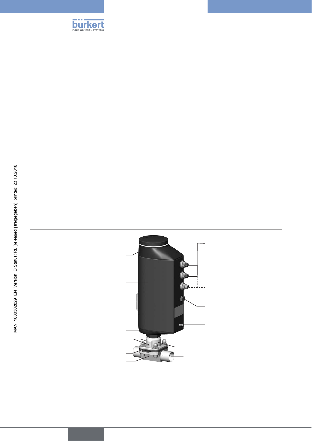
6.1 Diagram – structure of the electromotive
diaphragm control valve
Dummy cover or display with
illuminated display and bayonet catch
Actuator cover
Actuator housing
Transparent window with position
indicator
Actuator base
Electrical connections
(circular plug-in connector or
cable gland)
Applies only to devices with
process controller function
Pressure compensation element
Do not unscrew!
FE functional ground
14
2 Relief bores
Diaphragm socket
Diaphragm
Valve body
Figure 1: Structure, electromotive diaphragm control valve with 2-way body
Line connection
Type 3363, 3364, 3365
english
Structure and function
6.2 Valve position after failure of the supply voltage
Valve position when using devices without the SAFEPOS energy-pack:
If the electromotive actuator is at a standstill due to failure of the supply voltage, the valve remains in the last occupied
position.
If the supply voltage fails while the actuator is changing the valve position, the valve stops in an undefined position.
The actuator flywheel mass and the medium pressure continue to affect the valve spindle until it finally comes to a
standstill.
Valve position when using devices with the SAFEPOS energy-pack:
The valve occupies the safety position defined in the SAFEPOS menu.
Description of the SAFEPOS energy-pack see Chapter “7.3 SAFEPOS energy-pack (option)”, page 24
6.3 Safety position
The safety position defined in the SAFEPOS menu is the position which the valve occupies in the following cases:
• Internal error
• Sensor break if parameterized accordingly
• Digital input if parameterized accordingly
• Failure of the supply voltage (optional)
This function is available only on devices which have the optionally available SAFEPOS energy-pack.
The following safety positions are selected in the SAFEPOS menu:
• Close = Valve closed
• Open = Valve open
• User-Defined = Freely defined, safety position input by a percentage value
(0 % = closed, 100 % = open).
• Inactive = Valve stops in an undefined position if the supply voltage fails.
15
Type 3363, 3364, 3365
english
Structure and function
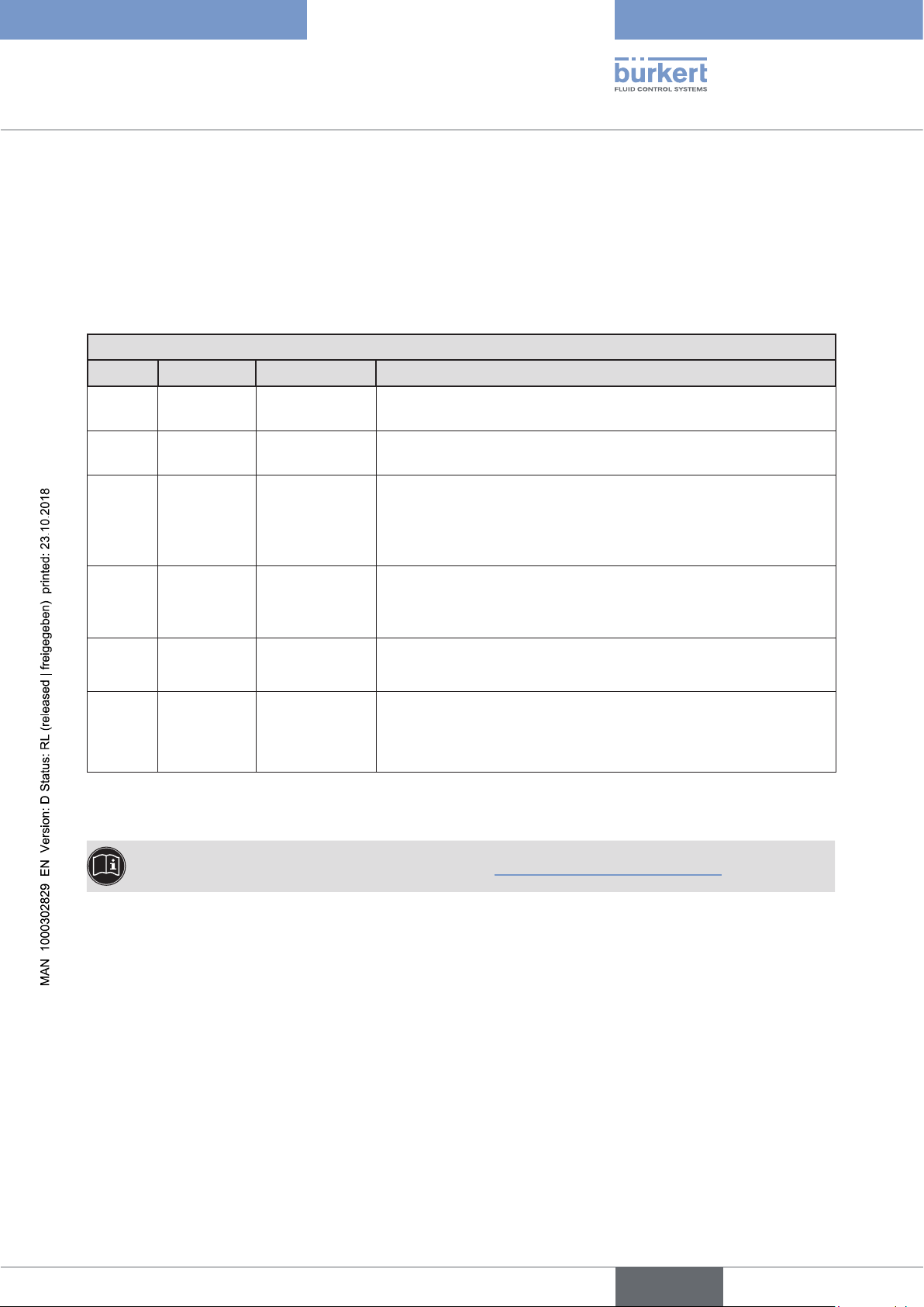
6.4 Display of the device state
The device state is indicated at the LED illuminated ring. To indicate the device status and the valve position, different LED modes can be set:
• Valve mode
• Valve mode w/ warnings (mode set in the factory)
• NAMUR mode
The description for setting the LED mode can be found in Chapter “12.2.2 Setting LED mode”, page 80.
6.4.1 Valve mode
The valve position and the device status “Failure” are indicated in the valve mode.
Messages for device status "Out of specification", "Maintenance required", and "Function check" are not
displayed in valve mode.
The factory default colors for indicating the open and closed valve positions can be changed.
A description can be found in the software description for Type 3363 on our homepage.
www.burkert.com
Displays in valve mode:
When device status “Normal”: Permanently lit in the color of the valve position.
When device status “Failure”: Flashes alternately red and in the color of the valve position.
Valve position Color of valve position Color of device status "Failure"
open
between
closed
Table 1: Display of device state in valve mode
yellow
white
green
rot
6.4.2 Valve mode w/ warnings
The valve position as well as the device status “Failure”, “Out of specification”, “Maintenance required”, and
“Function check” are displayed in this mode.
If several device statuses exist simultaneously, the device status with the highest priority is displayed. The priority is
determined by the severity of the deviation from standard operation (red = failure = highest priority).
Displays in valve mode w/ warnings:
When device status “Normal”: Permanently lit in the color of the valve position.
If device status deviates from “Normal”: The colors of the valve position and device status flash alternately.
16
Valve position Color of valve
position
open
between
closed
Table 2: Display of device state in valve mode w/ warnings
yellow red orange yellow blue
white
green
Color of device status
Failure, error or
fault
Function check Out of
specification
Maintenance
required
Type 3363, 3364, 3365
english
Structure and function
6.4.3 NAMUR mode
In NAMUR mode, the LED illuminated ring lights up according to NAMUR NE 107, in the color specified for the
device status.
If several device statuses exist simultaneously, the device status with the highest priority is displayed. The priority is
determined by the severity of the deviation from standard operation (red = failure = highest priority).
Displays in NAMUR mode:
Status display in accordance with NE 107, edition 2006-06-12
Color Color code Description Meaning
Red 5 Failure, error or
fault
Orange 4 Function check The device is being worked on; controlled operation is therefore
Yellow 3 Out of
specification
Due to a malfunction in the device or on its periphery, controlled
operation is not possible
temporarily not possible.
The ambient conditions or process conditions for the device are
outside the specified area.
Device internal diagnostics point to problems in the device or with
the process properties.
Blue 2 Maintenance
required
The device is in controlled operation, however function is briefly
restricted.
→ Maintain device.
Green 1 Diagnostics
active
White 0 Diagnostics
inactive
Table 3: Display of device status in NAMUR mode
* A detailed fault description can be found in Chapter “19.5 Troubleshooting”, page 145.
Device is operating faultlessly. Status changes are shown in color.
Messages are transmitted via any connected fieldbus.
Device is switched on.
Status changes are not shown.
Messages are not transmitted via any connected field bus.
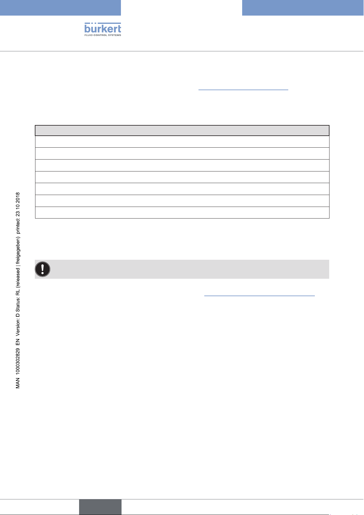
6.4.4 Flashing of the LED illuminated ring
Flashing indicates that a connection to the PC software “Bürkert Communicator” has been established.
17
Type 3363, 3364, 3365
english
Structure and function
6.4.5 Device status messages
Device status messages are displayed in the logbook. Chapter “19 Maintenance, troubleshooting” describes the
most common messages and the required action.
Messages for device status “Function check”
The messages are output when control mode is interrupted by work at the device.
Messages for device status “Function check”
Manual control active
M.SERVICE active
M.Q0.TUNE active
M.CLEAN active
P.LIN active
Process simulation active
Signal generator active
Table 4: Messages for device status “Function check”
6.5 Factory settings
Operating state:
Devices are delivered with the MANUAL operating state preset.
Find the factory presets for the individual menu points in Chapter “17 Operating structure / Factory settings”.
The factory settings are highlighted in blue to the right of the menu in the operating structure.
18
Type 3363, 3364, 3365
english
Electrical control
7 ELECTRICAL CONTROL
• Variants
Type 3363, 3364 oder 3365 with position controller function
Type 3363, 3364 oder 3365 with process controller function
• Position sensor
non-contact, high resolution and wear-free.
• Microprocessor-controlled electronics
for signal processing, control and motor control.
• Electrical interfaces
Circular plug-in connector or cable gland
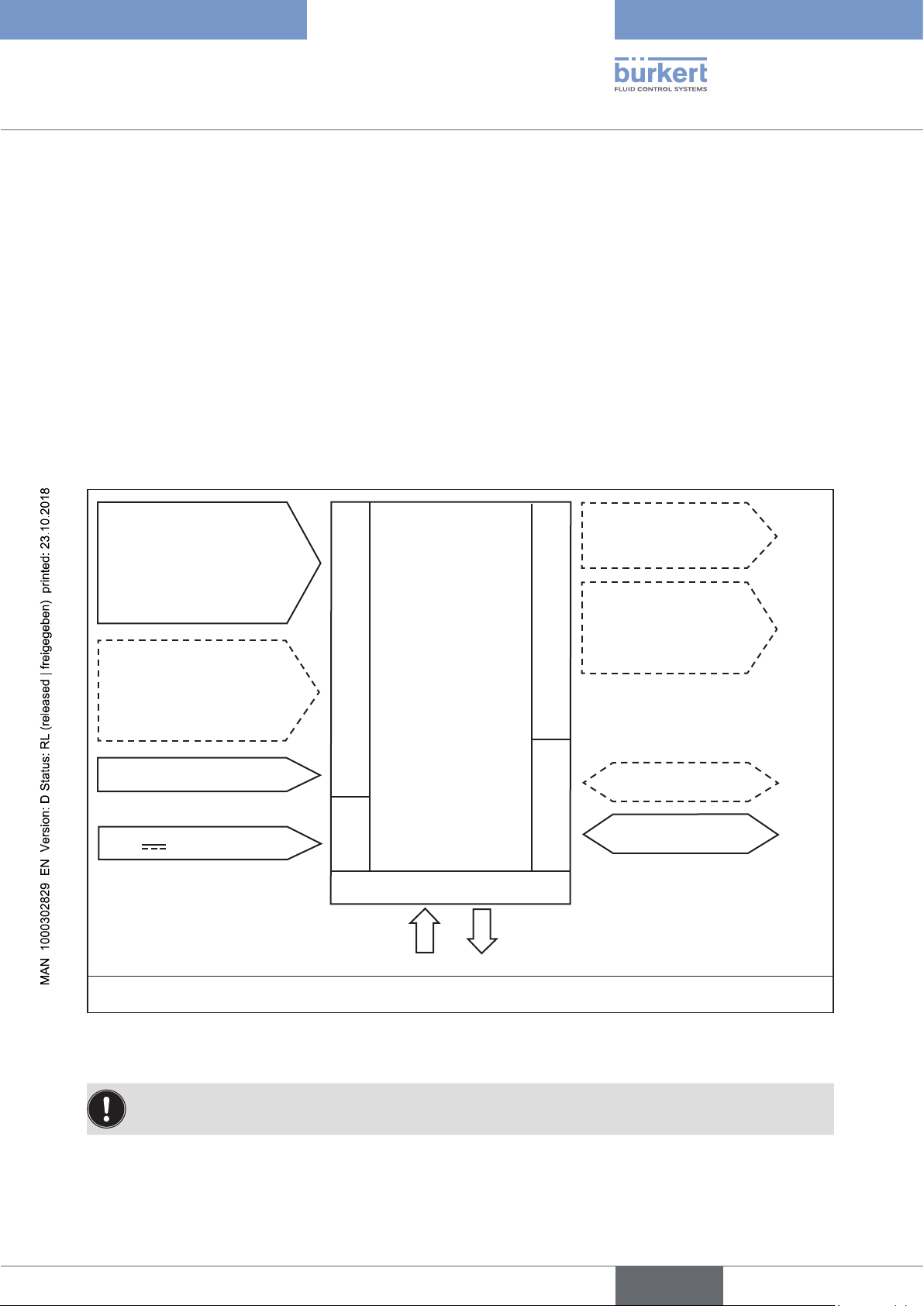
7.5.1 Interfaces
Input for set-point position
or process set-point value
4...20 mA
0...20 mA
0...10 V
0...5 V
Input for process actual
value*
4...20 mA
Frequency
Pt 100
Digital input
24 V
Electromotive
diaphragm control
valve
Inputs
Supply
Operation
2 digital outputs
24 V PNP
Analog
feedback
4...20 mA
0...10 V
Outputs
Fieldbus
büS / CANopen
Communication
Note:
Optional outputs are represented
as a broken line.
* Only available for devices with process controller function
Figure 2: Interfaces of the electromotive diaphragm control valve
The electromotive diaphragm control valve is designed using three-wire technology, i.e. the power (24 V DC)
is supplied separately from the set-point value signal.
19
Type 3363, 3364, 3365
english
Electrical control
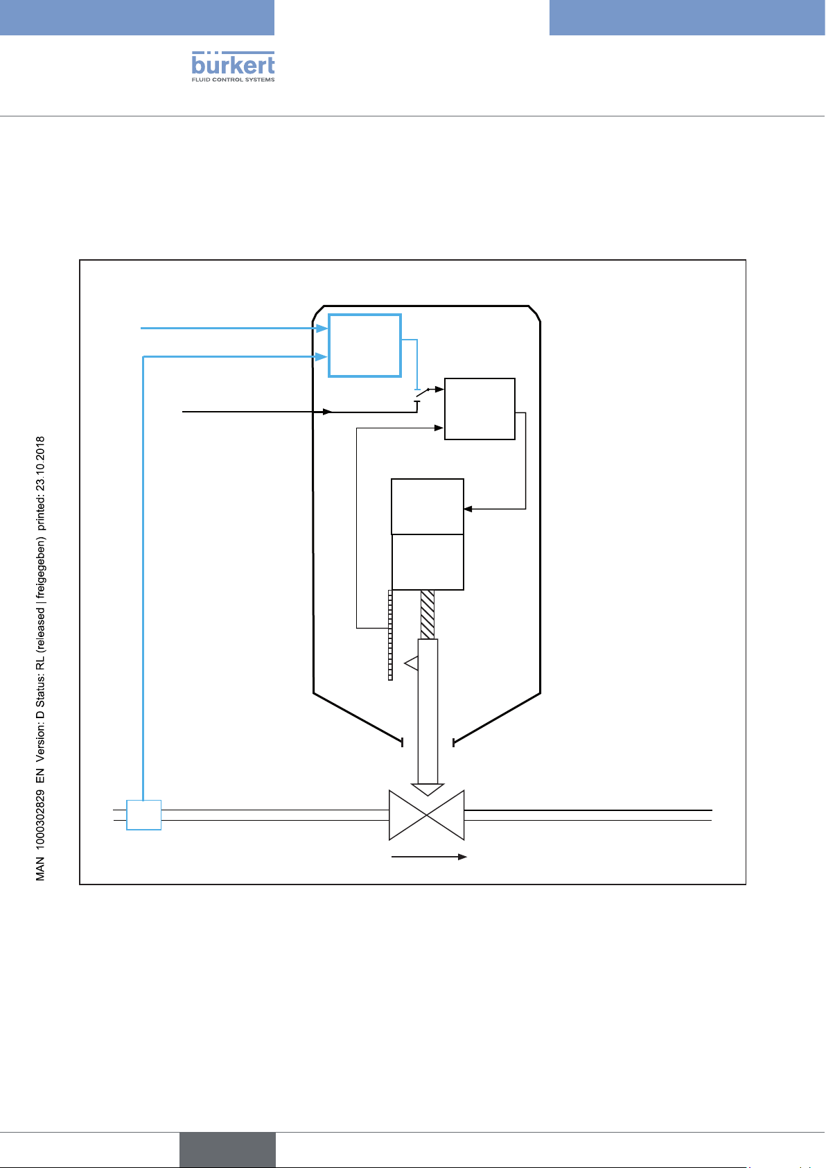
7.1 Function diagram of the electromotive diaphragm control valve
The black parts of the image describe the position controller function. The additional elements for the process
controller function (optional) are shown in blue.
Type 3363, 3364, 3365
Process set-point value
Process
Process actual value
control
External
set-point position
Position
Control
Actual
position
Motor
Gears
Position
sensor
20
Sensor
Figure 3: Function diagram of the electromotive diaphragm control valve
(actuating element)
Valve
Process actual value
(e.g. flow)
Type 3363, 3364, 3365
english
Electrical control
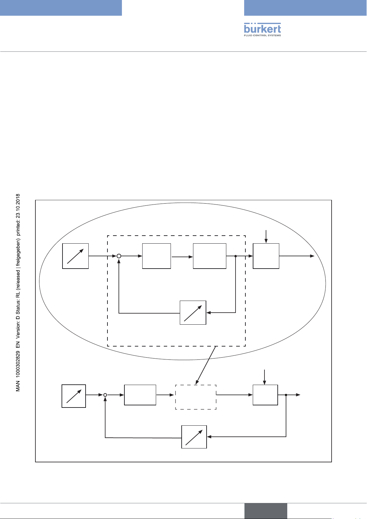
7.2 Operating mode of the electrical control
Apart from actual position control, the additionally implemented PID controller can also be used to perform process
control (e.g. level, pressure, flow, temperature) in the sense of a cascade control.
The process controller function is linked to a control circuit. The set-point position of the valve is calculated from
the process set-point value and the process actual value via the control parameters (PID controller). The process
set-point value can be specified by an external signal.
In process control the position control becomes the lower-level auxiliary control circuit, resulting in a cascade control.
The process controller in the main control circuit of the diaphragm control valve has a PID function. The process
set-point value (SP) is specified as set-point value and compared with the actual value (PV) of the process variable
to be controlled. The position sensor records the actual position (POS) of the electromotive linear actuator. This
position actual value is compared by the position control with the set-point value (CMD) of the process control. If
there is a control difference (Xd1), the actuating variable (CTRL) changes the actual position (POS) and therefore
the valve opening.
Signal flow plan
Set-point
position
SP
Process setpoint value
CMD Xd1
+
-
Xd2
+
-
Process
control
CTRL
Position
control
POS
Position control loop
CMD
Electromotive
actuator
Position sensor
Position
control loop
POS
Valve
opening
Z1
Valve
opening
Valve body
Z2
Process variable
Process
Figure 4: Signal flow plan
PV
Transmitter
21
Type 3363, 3364, 3365
english
Electrical control
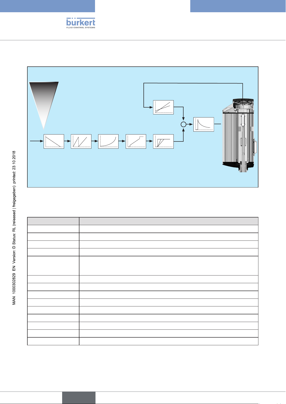
7.2.1 Schematic representation of the position control
Analog: 4...20 mA, 0...20 mA,
0...10 V, 0...5 V
Fieldbus gateway
POS
büS
X.LIMIT
Manual
CMD
CMD*
DIR.CMD SPLTRNG CHARACT CUTOFF X.TIME
Figure 5: Schematic representation of the position control
Legend for schematic representation of position control and process control:
Menu Description
X.LIMIT Limit of the mechanical stroke range
DIR.CMD Effective direction (set-point position)
SPLTRNG Signal split range
CHARACT Transfer characteristic
CUTOFF
(type X.CO)
(type P.CO)
Sealing function
(with regard to set-point position)
(with regard to process set-point value) point
X.TIME Limit of the control speed position control
X.CONTROL Parameterization position control
SP.scale Scaling process set-point value
SP.SLOPE Growth rate per time unit
SP.FILTER Filter for process set-point value
PV.scale Scaling process actual value
PV.FILTER Filter for process actual value
PID.PARAMETER Parameterization process control
P.CO. scale Scaling process control
X.CONTROL
22
Table 5: Legend, menu position control and process control
Type 3363, 3364, 3365
english
Electrical control
Process variables Description
POS
CMD
Position actual value
Set-point position
Position controller function: Selection of the source for the input
signal of the set-point position in the menu → Inputs/Outputs →
CMD → CMD.source.
Process controller function: The set-point position is specified by the
process controller.
CMD*
PV
Set-point position processed by the controller
Process actual value: Selection of the source for the input signal of the process actual
value in the menu → Inputs/Outputs → PV → PV.source.
PV*
SP
Process actual value processed by the controller
Process set-point value: Selection of the source for the input signal of the process setpoint value in the menu → Inputs/Outputs → SP I CMD → SP.source.
SP*
Table 6: Legend, process variables position control and process control
Process set-point value processed by the controller
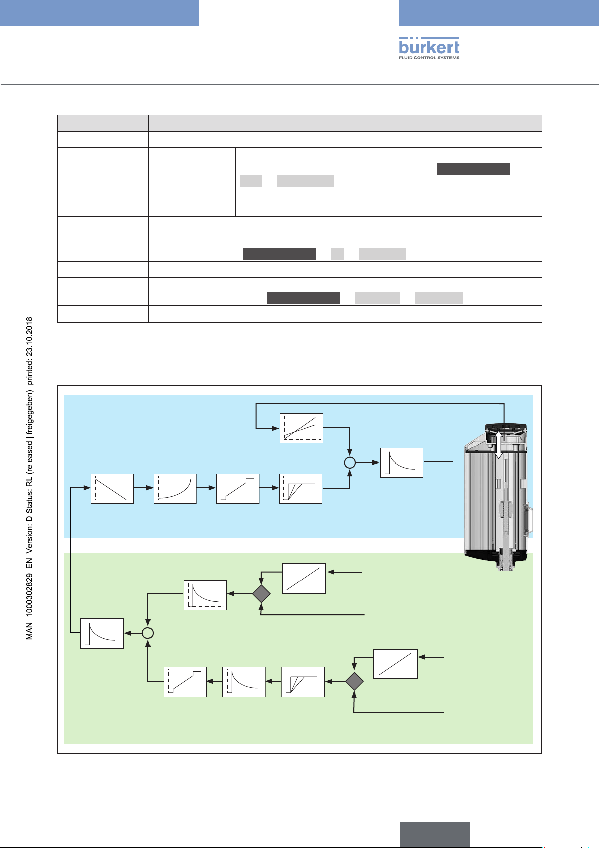
7.2.2 Schematic representation of the process control
Position control
POS
DIR.CMD CHARACT CUTOFF
(type X.CO)
Process control
PV*
PV.FILTER
–
+
PID.
PARAMETER
P.CO.scale
SP*
SP.FILTER
(type P.CO)
X.LIMIT
X.TIME
PV
PV.scale
SP.SLOPECUTOFF
–
+
X.CONTROL
CMD*
Analog: 4...20 mA
Frequency
PT100
büS
Analog: 4...20 mA
SP
SP.scale
büS
Fieldbus gateway
Manual
0...20 mA
0...10 V
0...5 V
Figure 6: Schematic representation of the process control
23
Type 3363, 3364, 3365
english
Electrical control
7.3 SAFEPOS energy-pack (option)
Optionally there is the energy pack (SAFEPOS energy-pack) for the device. If the supply voltage fails, the energy pack
supplies the actuator with the required energy to move the valve into the required position which can be adjusted
via a menu. The energy pack is fully charged and ready for use after a maximum of 100 seconds (depending on the
conditions of use).
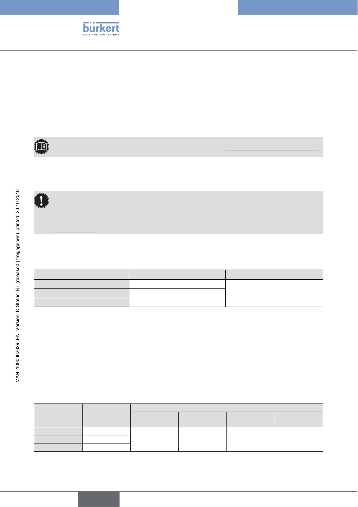
7.3.1 Service life
Service life: up to 10 years (depending on the conditions of use).
The determined service life of 7.5 years was determined under the following conditions:
Ambient temperature
Medium temperature 80 °C (176 °F)
Duty cycle
Medium pressure 6 bar (87,02 psi)
Diaphragm size 32
30 °C (86 °F)
100 %
ATTENTION!
The SAFEPOS energy-pack is a wearing part. Information on the service life are guide values which are not
guaranteed.
7.3.2 Messages on the state of the SAFEPOS energy-pack
The device issues a maintenance message:
The remaining life time of the energy storage is approx. 25 %! The energy storage must be changed soon.
▶ Replace SAFEPOS energy-pack in good time before the service life ends.
The device issues an error message and moves to the safety position:
The SAFEPOS energy-pack was not replaced in good time after the warning was issued. The storage capacity is
so low that there is no guarantee that the safety position can be approached.
7.3.3 Replacing SAFEPOS energy-pack
CAUTION!
Risk of injury due to electric shock.
▶ Before removing the SAFEPOS energy-pack, switch off the supply voltage.
▶ Completely drain SAFEPOS energy-pack. Wait until LED illuminated ring goes out; the LED status must not be in
LED off mode, see Chapter “12.2.2 Setting LED mode”.
24
The SAFEPOS energy-pack is housed in the actuator housing. To replace it, remove the following parts from the
actuator:
Devices with ATEX approval or IECEx approval are secured with a magnetic lock.
The removal of the cover is described in the additional manual for electromotive control valves with ATEX
approval and IECEx approval.
Type 3363, 3364, 3365
english
Electrical control
1. Dummy cover or display module
2. LED and storage module
3. Actuator cover.
The removal of these parts is described in detail in Chapter “10.2.2 Access to the connection terminals”, page 58.
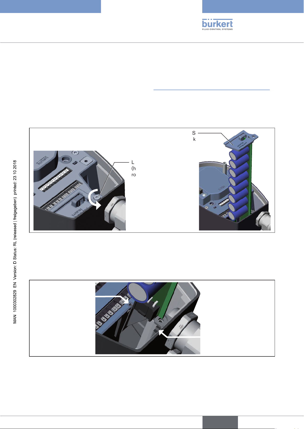
Removing SAFEPOS energy-pack:
→ Loosen the locking screw (hexagonal socket round screw T10).
→ Completely pull out the SAFEPOS energy-pack on the bracket.
SAFEPOS
energy-pack
Locking screw
(hexagonal socket
round T10)
Figure 7: Removing SAFEPOS energy-pack
Inserting new SAFEPOS energy-pack:
→ Take the SAFEPOS energy-pack out of the transport packaging.
→ Insert the SAFEPOS energy-pack into the two lateral guiding grooves and push in all the way.
Guiding groove
Guiding groove
Figure 8: Inserting SAFEPOS energy-pack
→ Tighten the locking screw (hexagonal socket round screw T10).
→ Apply supply voltage.
25

8 TECHNICAL DATA
english
The following product-specific information is indicated on the rating plate:
• Voltage [V] (tolerance ±10 %) and current type
• Diaphragm material and material of the valve body
• Fieldbus standard
• Diaphragm size
• Flow capacity
• Actuator size
• Line connection
• Maximum permitted medium pressure
8.1 Conformity
Type 3363, 3364, 3365
Technical data
The electromotive diaphragm control valves Type 3363, 3364 and 3365 are compliant with EU directives as stated in the
EU Declaration of Conformity.
8.2 Standards
The applied standards, which are used to demonstrate compliance with the EU Directives, are listed in the EU type
test certificate and/or the EU Declaration of Conformity.
8.3 Licenses
The product is cULus approved. Instructions for use in the UL area see chapter “8.9 Electrical data”.
26
Type 3363, 3364, 3365
english
Technical data
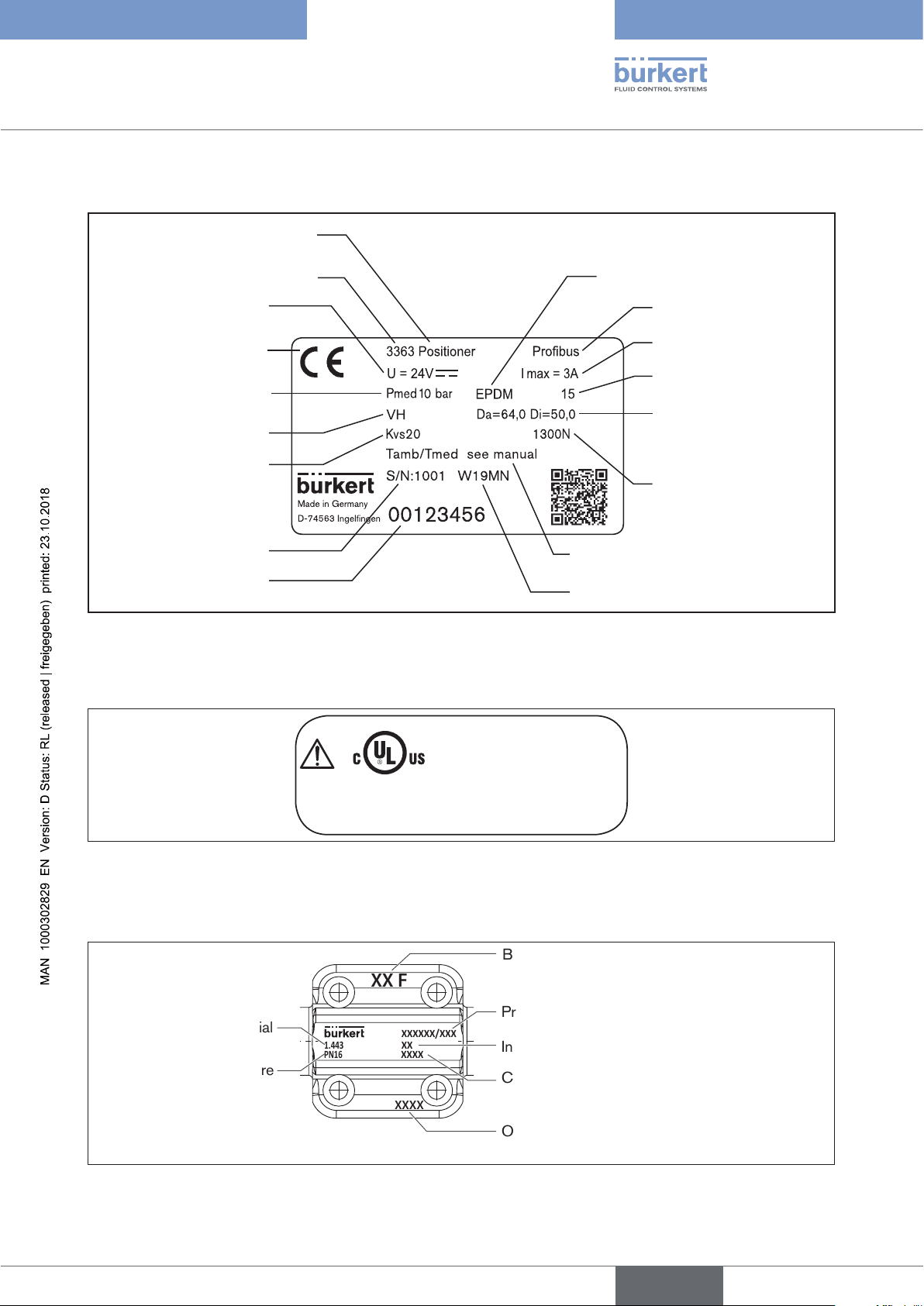
8.4 Type label
Function (Positioner / Process
controller)
Type
Voltage, direct current
CE marking
Maximum permitted
medium pressure
Material valve body
Flow capacity
Serial number
Identification number of
the device
Figure 9: Description of the type label (example)
8.4.1 UL additional label (Example)
Diaphragm material
Fieldbus standard
Maximum current
Diaphragm size
Line connection
Da (ø outer)
Di (ø inner)
Actuator size
(nominal force)
Permitted temperature range
(surrounding area/medium)
Date of manufacture (encoded)
Type AE3360
Power Supply
LISTED
Process Control Equipment
E238179
Figure 10: UL additional label (example)
SELV / PELV only!
8.5 Labeling of the forged bodies
Batch number
XX F
Production number / serial number
Material
1.4435/316L(VS)
PN16/CWP150
Nominal pressure
Figure 11: Labeling of the forged bodies
XXXXXXXX/XXX
XXXX
XXXXXX
XXXXXXXXXX
Inclination angle for self-draining
Customer-specific text (optional)
Orifice connection and pipe dimension
27
Type 3363, 3364, 3365
english
Technical data
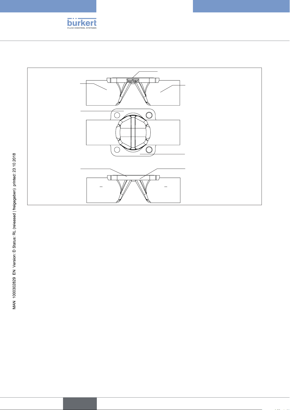
8.6 Labeling of the tube valve bodies (VP)
Company logo
Material
1.4435
316L(VP)
Nominal pressure
Production number
order number /
Serial number
Figure 12: Labeling of the tube valve bodies (VP)
PN16 / CWP150
XXXXXXXXXX
XXXXXXXX / XXX
XXXX / XXXXXX
Heat
XXXXXXXX
Orifice connection and pipe
dimension
Surface quality code / Customer-specific text (optional)
28
Type 3363, 3364, 3365
english
Technical data
8.7 Operating conditions
For operation of the device observe the product-specific information on the rating plate.
WARNING!
Malfunction if the temperature exceeds or drops below the permitted temperature range.
▶ Never expose the device outdoors to direct sunlight.
▶ The temperature must not exceed or drop below the permitted ambient temperature range.
WARNING!
Reduced sealing function if medium pressure too high.
As the diaphragm control valve is closed against the medium flow, the medium pressure may become too high
and prevent the valve from closing tightly.
▶ The medium pressure must not be greater than the maximum value specified on the
rating plate.
WARNING!
Danger due to escape of hot medium.
The diaphragm is not permanently temperature-resistant to hot medium.
▶ Do not use the diaphragm control valve for steam shut-off.
Maximum permitted medium pressure: see rating plate
Media: neutral, high-purity, sterile, contaminated, aggressive or abrasive media with high to
semi-fluid viscosity.
Degree of protection: (verified by Bürkert / not evaluated by UL)
IP65/67 according to IEC 529, EN 60529, (IP67 on request).
NEMA 250 4x (not guaranteed for installation location: actuator facing downward).
Altitude: up to 2000 m above sea level.
8.7.1 Permitted temperature ranges
The permitted medium and ambient temperature ranges depend on various factors:
• Medium temperature: depends on the material of the valve body and diaphragm materials.
See chapter “8.7.2 Permitted medium temperature”
• Ambient temperature: depends on the medium temperature. See “Figure 14: Temperature graph”.
To determine the permitted temperatures, all factors must be taken into account.
29
Type 3363, 3364, 3365
english
Technical data
Minimum temperatures Environment: –10 °C (14 °F)
Medium: Observe dependence on material of the valve body and diaphragm
materials. See chapter “8.7.2 Permitted medium temperature”
Maximum temperatures Observe dependencies on ambient temperature and medium temperature. See
chapter “8.7.3 Temperature graph for medium and ambient temperature”
8.7.2 Permitted medium temperature
ATTENTION!
The behavior of the medium with respect to the diaphragm materials may change depending on the medium
temperature.
▶ The indicated medium temperatures apply only to media which do not corrode or swell the diaphragm
materials.
▶ The functional properties, and the life time of the diaphragm, may be impaired if the temperature rises or
drops below the indicated medium temperature.
Permitted medium temperature for diaphragm materials
Permitted medium temperature range
Diaphragm material
minimal maximal Steam sterilisation
EPDM (AB), PTFE/EPDM (EA) -10 °C (14 °F) +130 °C (266 °F) +140 °C/60 min. (284 °F/60 min.)
EPDM (AD) ,advanced PTFE/
-5 °C (23 °F) +143 °C (289.4 °F) +150 °C/60 min. (302 °F/60 min.)
EPDM (EU)
GYLON / EPDM laminated (ER) -5 °C (23 °F) +130 °C (266 °F) +140 °C/60 min. (284 °F/60 min.)
FKM (FF) 0 °C (32 °F) +130 °C (266 °F) No steam / dry heat up to +150 °C/60
min. (302 °F/60 min.)
Table 7: Permitted medium temperature depending on the diaphragm materials
Permitted medium temperature for valve bodies made of metal
Valve body material Permitted temperature range
Stainless steel -10...+150 °C (14...302 °F)
Cast body (VG)
Forged body (VS)
Tube valve body (VP)
Table 8: Medium temperature for valve bodies
30
 Loading...