

Page 1
Type 2035 / 3236
Robolux multiple-way diaphragm valve
Robolux Mehrwege-Membranventil
Vanne à membrane multi-voies Robolux
Operating Instructions
Bedienungsanleitung
Manuel d‘utilisation
Page 2
We reserve the right to make technical changes without notice.
Technische Änderungen vorbehalten.
Sous réserve de modifications techniques.
© 2005 - 2013 Bürkert Werke GmbH
Operating Instructions 1312/11_EU-ML_00804204 / Original DE
Page 3
Type 2035 / 3236
Contents
1. OPERATING INSTRUCTIONS ...................................................................5
1.1. Symbols ..............................................................................................5
1.2. Definition of term / abbreviation ....................................................5
2. AUTHORIZED USE .........................................................................................6
2.1. Restrictions ........................................................................................6
3. BASIC SAFETY INSTRUCTIONS .............................................................6
3.1. Use in Ex area ...................................................................................7
3.2. Special conditions ...........................................................................9
4. GENERAL INFORMATION ...........................................................................9
4.1. Contact address ............................................................................... 9
4.2. Warranty ............................................................................................. 9
4.3. Information on the Internet ............................................................. 9
4.4. Trademarks ......................................................................................10
5. PRODUCT DESCRIPTION ........................................................................ 10
5.1. General description .......................................................................10
5.2. Device versions ...............................................................................10
5.3. Valve self-draining ..........................................................................12
5.4. Valve symbols and flow diagrams ................................................ 13
5.5. Valve marking ..................................................................................15
5.6. Intended application area .............................................................17
6. STRUCTURE AND FUNCTION...............................................................17
6.1. Structure of Type 2035.................................................................17
6.2. Structure of Type 3236.................................................................18
7. TECHNICAL DATA ........................................................................................19
7.1. Conformity .......................................................................................19
7.2. Standards .........................................................................................19
7.3. Approvals .........................................................................................19
7.4. Type label .........................................................................................19
7.5. Operating conditions .....................................................................19
7.6. Mechanical data .............................................................................19
7.7. Fluidic data ......................................................................................21
8. ASSEMBLY .......................................................................................................23
8.1. Safety instructions .........................................................................23
8.2. Before installation ...........................................................................23
8.3. Installation ........................................................................................24
8.4. Pneumatic connection (Type 2035 only) ..................................25
8.5. Installation of the inductive proximity switch ............................26
9. OPERATION AND FUNCTION ................................................................27
9.1. Safety instructions .........................................................................27
9.2. Type 2035 - pneumatic operation ..............................................27
9.3. Type 3236 - manual operation ....................................................28
10. ELECTRICAL PRE-CONTROLLER ...................................................... 28
11. DISASSEMBLY ............................................................................................ 28
12. MAINTENANCE, CLEANING ................................................................. 29
12.1. Safety instructions .......................................................................29
12.2. Servicing intervals ........................................................................29
12.3. Servicing work ..............................................................................29
12.4. Cleaning .........................................................................................30
english
3
Page 4
13. REPAIRS ......................................................................................................... 31
13.1. Safety instructions .......................................................................31
13.2. Replacing the diaphragm ...........................................................31
14. SPARE PARTS ............................................................................................. 40
14.1. Order table ....................................................................................40
15. MALFUNCTIONS ........................................................................................ 41
16. TRANSPORT, STORAGE, PACKAGING .......................................... 41
Type 2035 / 3236
4
english
Page 5
Type 2035 / 3236
Operating instructions
1. OPERATING INSTRUCTIONS
The operating instructions describe the entire life cycle of the device.
Keep these instructions in a location which is easily accessible to
every user and make these instructions available to every new owner
of the device.
WARNING!
The operating instructions contain important safety information.
Failure to observe these instructions may result in hazardous
situations.
▶ The operating instructions must be read and understood.
1.1. Symbols
DANGER!
Warns of an immediate danger.
▶ Failure to observe the warning will result in a fatal or serious injury.
WARNING!
Warns of a potentially dangerous situation.
▶ Failure to observe the warning may result in serious injuries or
death.
CAUTION!
Warns of a possible danger.
▶ Failure to observe this warning may result in a moderate or minor
injury.
NOTE!
Warns of damage to property.
▶ Failure to observe the warning may result in damage to the device
or the equipment.
Indicates important additional information, tips and
recommendations.
Refers to information in these operating instructions or in
other documentation.
▶ Designates an instruction to prevent risks.
→ Designates a procedure which you must carry out.
1.2. Definition of term / abbreviation
In these instructions, the term 'device' always refers to the Robolux
Multiway Diaphragm Valve Type 2035 / 3236.
In these instructions, the term 'diaphragm valve' always refers to the
Robolux Multiway Diaphragm Valve Type 2035 / 3236.
In these instructions, the abbreviation “Ex” always refers
to “potentially explosive”.
english
5
Page 6
Type 2035 / 3236
Authorized use
2. AUTHORIZED USE
Improper use of the Robolux Multiway Diaphragm Valve Type
2035 / 3236 may represent a hazard to persons, neighboring
equipment and the environment.
The device is designed for controlling the flow-rate of liquid media.
▶ The approved data, the operating conditions and conditions of use
specified in the contract documents, operating instructions and on
the type label are to be observed during use. The designated areas
of application are specified in chapter "5. Product description".
▶ Use the device only in conjunction with third-party devices and
components recommended and authorized by Bürkert.
▶ Correct transportation, storage, and installation, as well as care-
ful use and maintenance are essential for reliable and faultless
operation.
▶ Use the device only as intended.
2.1. Restrictions
If exporting the system/device, observe any existing restrictions.
3. BASIC SAFETY
INSTRUCTIONS
These safety instructions do not make allowance for any
• Contingencies and events which may arise during the installation,
operation, and maintenance of the devices.
• Local safety regulations – the operator is responsible for observing
these regulations, also in relation to the installation personnel.
DANGER!
Risk of injury from high pressure in the equipment/device.
▶ Before working on equipment or device, switch off the pressure
and deaerate/drain lines.
Risk of electric shock.
▶ Before working on equipment or device, switch off the power
supply and secure to prevent reactivation.
▶ Observe applicable accident prevention and safety regulations
for electrical equipment.
WARNING!
Risk of injury when opening the actuator.
The actuator contains tensioned springs. If the actuator is opened,
injuries may be caused by the springs jumping out!
▶ The actuator must not be opened.
6
english
Page 7
Type 2035 / 3236
Basic safety instructions
CAUTION!
Risk of burns.
The surface of the device may become hot during long-term
operation.
▶ Do not touch the device with bare hands.
Generally hazardous situations.
To prevent injuries:
▶ Ensure that the system cannot be activated unintentionally.
▶ Installation and repair work may be carried out by authorized
technicians only and with the appropriate tools.
▶ After an interruption in the electrical or pneumatic supply, ensure
that the process is restarted in a defined or controlled manner.
▶ The device must only be operated when in a perfect condition and
in consideration of the operating instructions.
▶ The general rules of technology must be observed for application
planning and operation of the device.
To prevent material damage:
▶ Supply only media to the media connections that are specified in
chapter "7. Technical Data" as flow media.
▶ Do not place the valve under mechanical stress (e.g. by placing
objects on it or standing on it).
▶ Do not make any external alterations to the valves. Do not apply
paint to body parts or screws.
3.1. Use in Ex area
Abbreviation “Ex”: see chapter "1.2. Definition of term / abbreviation"
3.1.1. Safety instructions
For operation in Ex area Zone (gas) 1 and 2,
Zone (dust) 21 and 22, the following
applies:
The valve actuator is suitable for use as a Category 2 device for
Zone 1 and 21, non-electrical production equipment.
DANGER!
Danger of explosion caused by electrostatic charge.
Depending on the conductivity of the medium, electrostatic charges
may occur on the valve membrane if plastic bodies are used.
To prevent electrostatic charges in the fluid, the following instructions
must be observed (as per IEC 60079-32-1):
▶ (1) Media with a conductivity ≤ 100 pS/m may only be used if no
flow speeds > 1 m/s occur or if the possibility of the pipe system
running dry is excluded by suitable monitoring.
▶ (2) Media with a conductivity > 100 pS/m and ≤ 1000 pS/m may
only be used if they are liquids without any particles, steam or pure
gases/steam, or if the instructions in (1) are observed.
▶ (3) Media with a conductivity > 1000 pS/m are not subject to any
restrictions.
english
7
Page 8
Type 2035 / 3236
Basic safety instructions
Further instructions:
▶ The user must ensure that the appliance is used in Zone 1/21 or
2/22 only.
▶ The attachment of feedback indicators may restrict use in an
explosive atmosphere. Follow operating instructions for feedback
indicator.
▶ Check that any cleaning agents are approved for use in explosive
atmospheres.
3.1.2. Media temperature
DANGER!
▶ If explosive media are used this can cause additional explosion risks.
▶ If media temperatures are used between 130 °C and 150 °C, the
temperature class T3 / 200 °C applies (dust).
Media temperature The media temperature must not be higher
than the target temperature class.
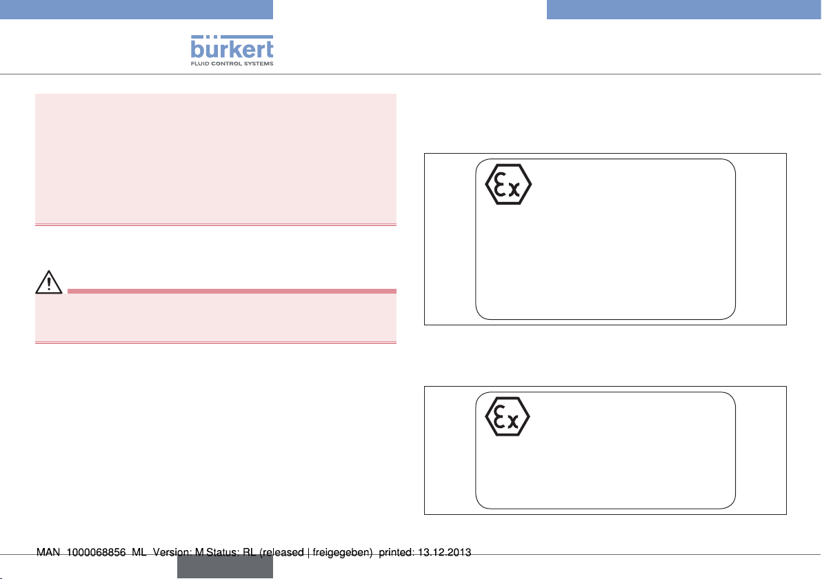
3.1.3. Marking and warning notices in Ex
area
Type 2035
PTB 13 ATEX D103 X
II 2G c IIC T6
II 2D c T85°C
Warning:
Not valid when Non-Ex devices added.
Do not open actuator. Spring loaded cover.
Clean the surface with appropriate
cleaning agent only!
Fig. 1: Type 2035 marking and warning notices in Ex area
Type 3236
PTB 13 ATEX D103 X
II 2G c IIC T6
II 2D c T85°C
Caution:
Clean the surface with appropriate
cleaning agent only!
Fig. 2: Type 3236 marking and warning notices in Ex area
8
english
Page 9
Type 2035 / 3236
General information
The Ex marking is not valid if Non-Ex devices are added.
3.2. Special conditions
→ To ensure potential equalization, ground the valve body to the
pipe system using an electrically conductive connection.
DANGER!
Danger of explosion caused by electrostatic charge.
In the event of a sudden discharge from electrostatically charged
devices or individuals there is a risk of an explosion in the Ex area.
▶ Implement suitable measures to ensure that there are no electro-
statically charges in the Ex area (see also "3.1. Use in Ex area").
▶ Clean the device surface by gently wiping it with a damp or anti-
static cloth only.
▶ Earth the actuator and valve body.
▶ If a plastic body is used, earth the actuator separately.
Ambient temperature range: -10 °C ≤ Tamb ≤ 60 °C
4. GENERAL INFORMATION
4.1. Contact address
Germany
Bürkert Fluid Control Systems
Sales Center
Christian-Bürkert-Str. 13-17
D-74653 Ingelfingen
Tel. + 49 (0) 7940 - 10 91 111
Fax + 49 (0) 7940 - 10 91 448
Email: info@de.buerkert.com
International
Contact addresses can be found on the final pages of the printed
operating instructions.
And also on the Internet at: www.burkert.com
4.2. Warranty
The warranty is only valid if the diaphragm valve is used as intended in
accordance with the specified application conditions.
4.3. Information on the Internet
The operating instructions and data sheets for Types 2035 / 3236 can
be found on the Internet at:
www.burkert.com
english
9
Page 10
Type 2035 / 3236
Product description
4.4. Trademarks
Brands and trademarks listed below are trademarks of the respective
companies / associations / organizations:
PFR 91 Solvey Solexis Inc.
PFA DuPont Performance Elastomers
Inbus Textron Verbindungstechnik GmbH & Co. oHG
5. PRODUCT DESCRIPTION
5.1. General description
The manually or pneumatically operated Robolux Multiway Diaphragm Valves
of ultra-pure, sterile, aggressive or abrasive media. They allow for
optimal collection, draining or distribution of critical process media.
1) In the following text the Robolux Multiway Diaphragm Valve is
referred to as 'diaphragm valve' for brevity's sake.
5.2. Device versions
The diaphragm valve is available in two variants with either a pneumatically or manually operated valve.
The diaphragm valve can be adapted to very different usage conditions on account of its modular design.
Depending on the connection size of the diaphragm valves three
construction sizes are available (RV5O, RV7O, RV110).
The valve body is made from a stainless steel block. For certain
usage conditions valve bodies made of plastic (PVDF or PP) are
available.
1)
have been designed as a system for the control
Observe instructions on operation in an explosion-risk (Ex)
area. See chapter "3.1. Use in Ex area".
10
english
Page 11
Type 2035 / 3236
Product description
High-quality diaphragms ensure complete separation of the critical
medium from the actuator.
Depending on the function the valve can have one, two or three
actuators.
The diaphragm valves can be used for a large variety of control functions. Accordingly, there is a very wide range of configuration variations. For instance, according to function:
• the valves in the actuator can vary,
• the actuators can have one or two control pistons that can be
operated independently of each other,
• pneumatic actuators can be equipped with inductive proximity
switches for querying the various switching states.
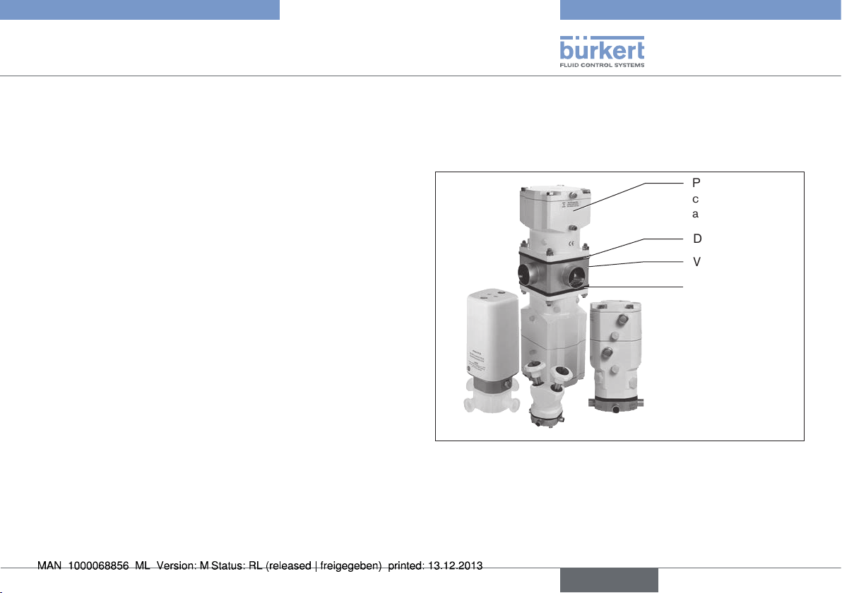
5.2.1. Pneumatically operated diaphragm
valve Type 2035
The valve has one or two pneumatic actuators that are controlled via
compressed air.
Pneumatically operated
actuator
Diaphragm
Valve body
Diaphragm
Fig. 3: Pneumatically operated diaphragm valve, structure and
description
english
11
Page 12
Type 2035 / 3236
Product description
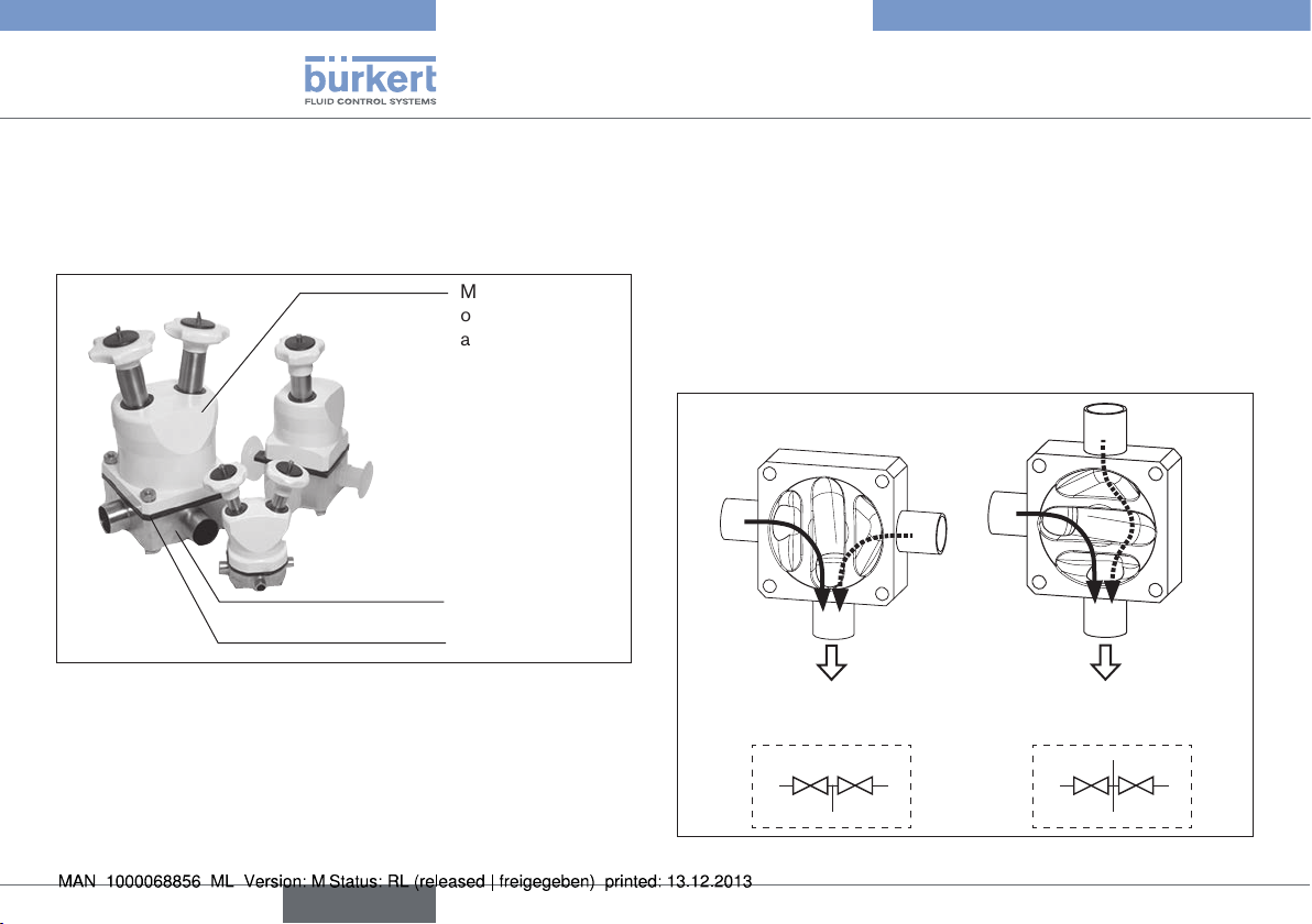
5.2.2. Manually operated diaphragm valve
Type 3236
The valve is operated manually.
Manually
operated
actuator
Valve body
Diaphragm
Fig. 4: Manually operated diaphragm valve, structure and
description
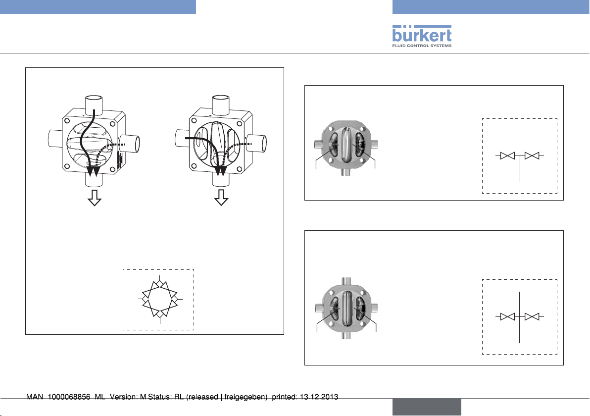
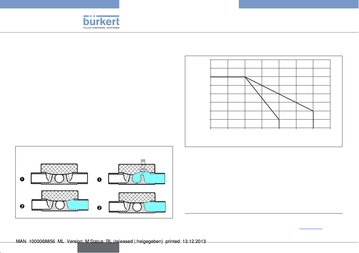
5.3. Valve self-draining
The way in which self-draining takes place varies according to the
valve type. It is very important to know the flow paths for each individual valve before the port / connection (marked with A, B, C or D)
for draining is selected.
Contact your Bürkert sales office or our Sales Center, email:
info@de.buerkert.com if you have any queries.
The following examples illustrate draining for the valve types 3C2S /
4C2S and 4C4S DFP.
Installation positions for self-drainage:
A
B
3C2S / 4C2S
drainage connection B (D)
A
C
C
B
drainage connection C (A)
A
C
3C2S / 4C2S
A
D
C
12
english
B
Fig. 5: Self-draining - 3C2S / 4C2S
B
Page 13
Type 2035 / 3236
Product description
Installation positions for self-drainage:
C
D
A
4C4S DFP
drainage connection
A (C)
Fig. 6: Self-draining - 4C4S DFP
B
A
B
A
4C4S DFP
drainage connection
B (D)
D
C
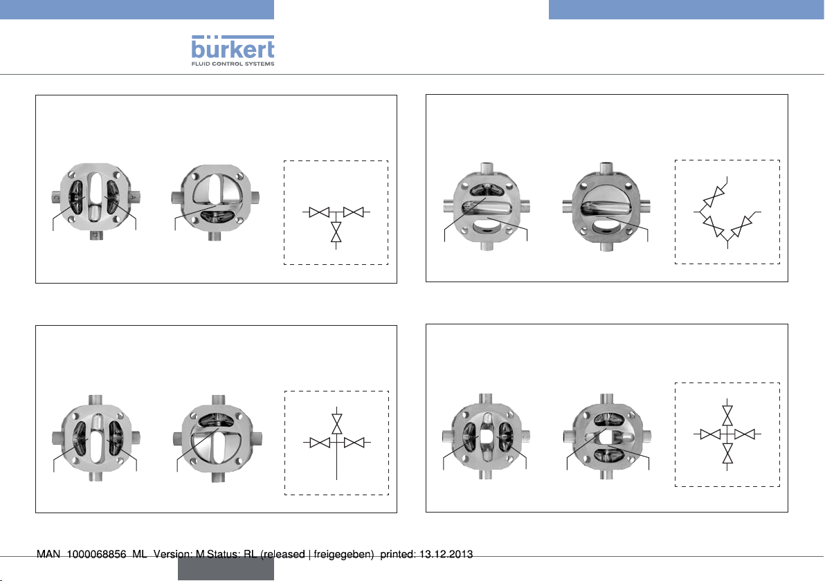
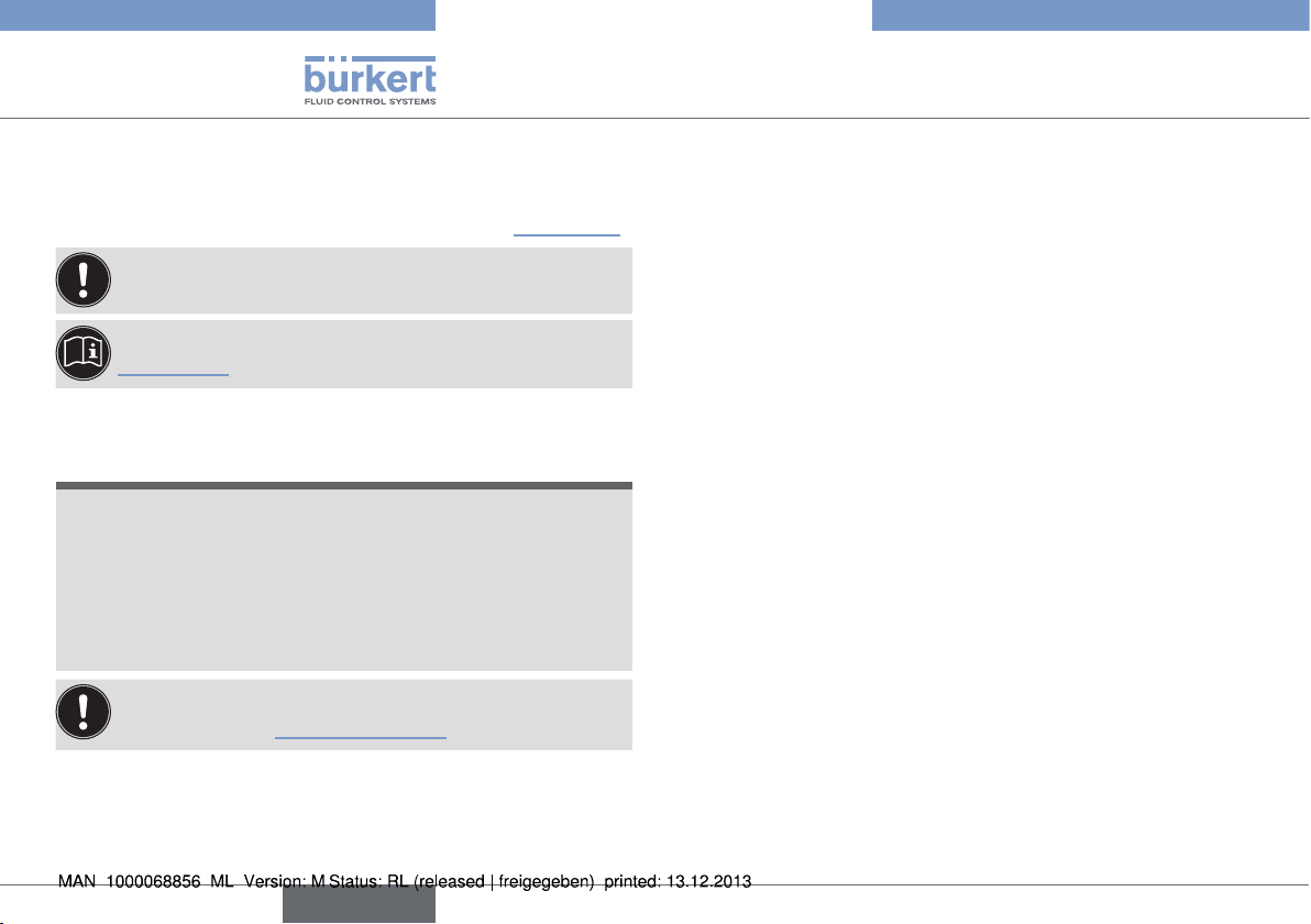
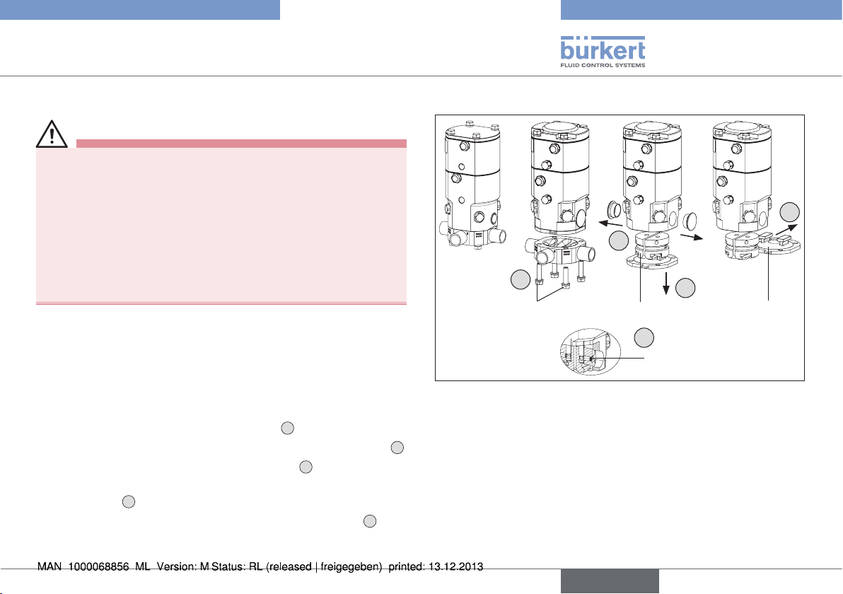
5.4. Valve symbols and flow diagrams
3 connections, 2 seats
D
C
B
A
Seat
U1
Fig. 7: Valve symbols and flow diagrams - 3C2S
A
Seat
U1
B
D
B
C
Seat
U2
4 connections, 2 seats
C
Seat
U2
3C2S
4C2S
A
A
C
B
D
C
B
Fig. 8: Valve symbols and flow diagrams - 4C2S
english
13
Page 14
Type 2035 / 3236
Product description
3 connections, 3 seats
3C3S
upper side lower side
A
C
Seat
U1
Fig. 9: Valve symbols and flow diagrams - 3C3S
A C
Seat
U1
D
upper side lower side
D
B
A
Seat
Seat
Seat
U2
U2
L1
4 connections, 3 seats
C A
Seat
L1
D
4C3S
D
B
C
C
A
4 connections, 3 seats
4C3S BD filter valve
upper side lower side
A
A
D
D
C
B
B
Seat
U1
Fig. 11: Valve symbols and flow diagrams - 4C3S BD
A
Seat
U1
C
upper side lower side
D
B
D
D
Seat
U2
4 connections, 4 seats
C
C
Seat
U2
Seat
L1
A
C
4C4S
D
B
Seat
L2
Seat
L2
A
B
B
A
A
D
C
D
C
B
Fig. 10: Valve symbols and flow diagrams - 4C3S
14
english
Fig. 12: Valve symbols and flow diagrams - 4C4S
Page 15
Type 2035 / 3236
Product description
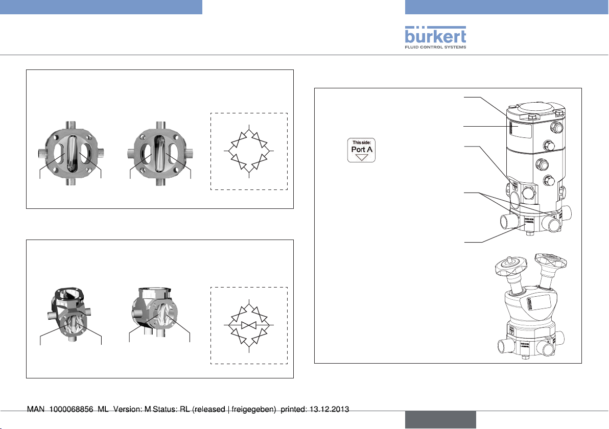
4 connections, 4 seats
4C4S DFP through-flow double valve
upper side lower side
D
A
Seat
U1
Fig. 13: Valve symbols and flow diagrams - 4C4S DFP
Seat
U1
Fig. 14: Valve symbols and flow diagrams - 4C5S
B
upper side lower side
A
B1
C
C
Seat
C
Seat
Seat
U2
4 connections, 5 seats
4C5S chromatography valve
C
Seat
U2
L1
L1
B1
D
B
B2
Seat
L2
A
Seat
L2
A
A
A
D
B
B1
B2
5.5. Valve marking
Marking and warning
notices in Ex area
Type label
C
Orifice and connection dimensions
Material, charge, manufacturing
C
Fig. 15: Valve marking
Actuator orientation
marking
Port connection
markings
Valve body labeling
order and serial No.
english
15
Page 16
Type 2035 / 3236
Product description
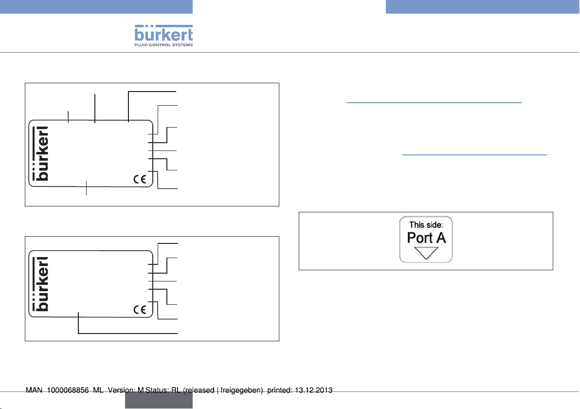
5.5.1. Type label
Size
Type
2035 RV50 4C 4S-DFP
EPDM-cus D11 -D11
Weld end 19.05x1.65
Pilot 4.2-10 bar
Pmed 10bar
Made in Germany
12345678
Identification number
Fig. 16: Type label Type 2035
Robolux
3236 RV50 4C 4S-DFP
EPDM-cus D44 -D44
Weld end 19.05x1.65
Pmed 10bar
Made in Germany
12345678
Fig. 17: Type label Type 3236
W14UN
W14UN
Design
Diaphragm material -
actuator 1 - actuator 2
Connection type -
connection dimensions
Pilot pressure
Max. medium pressure
Date of manufacture
Type - Size - Design
Diaphragm material -
actuator 1 - actuator 2
Connection type -
connection dimensions
Max. medium pressure
Date of manufacture
Identification number
5.5.2. Marking and warning notices in Ex
area
See chapter "3.1.3. Marking and warning notices in Ex area".
5.5.3. Port connection markings
All port connections are provided with letters corresponding to the
flow diagrams (see chapter "5.4. Valve symbols and flow diagrams").
5.5.4. Actuator orientation marking
The actuator has a marking close to connection A as an aid to
ensure correct assembly.
Fig. 18: Actuator orientation marking
16
english
Page 17
Type 2035 / 3236
Structure and function
5.6. Intended application area
The diaphragm valve has been designed for use with soiled and
aggressive media which do not corrode the body and the seal
materials.
Observe the maximum pressure range according to the
type label.
• Ultra-pure, sterile, aggressive or abrasive media.
• Highly viscous media.
Observe instructions on operation in an explosion-risk (Ex)
area. See chapter "3.1. Use in Ex area".
5.6.1. Application areas
e.g. plant construction
luxury food and food processing industry
bottling plant
chemical engineering
pharmaceutics
6. STRUCTURE AND FUNCTION
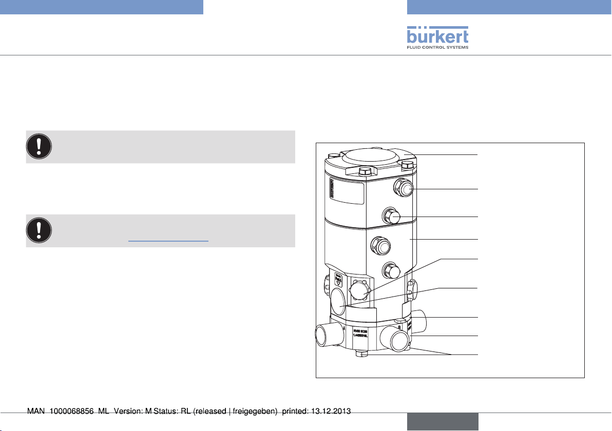
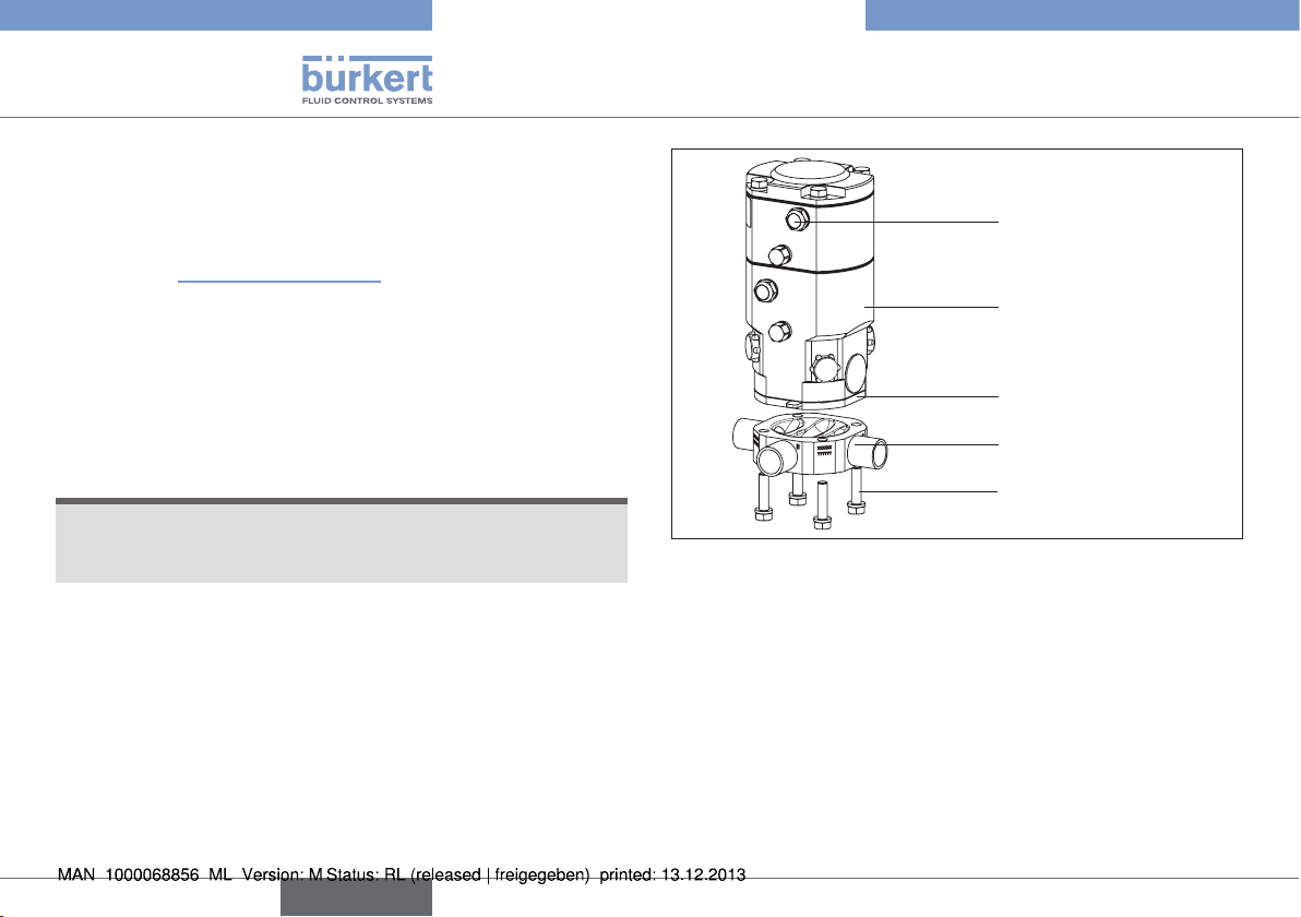
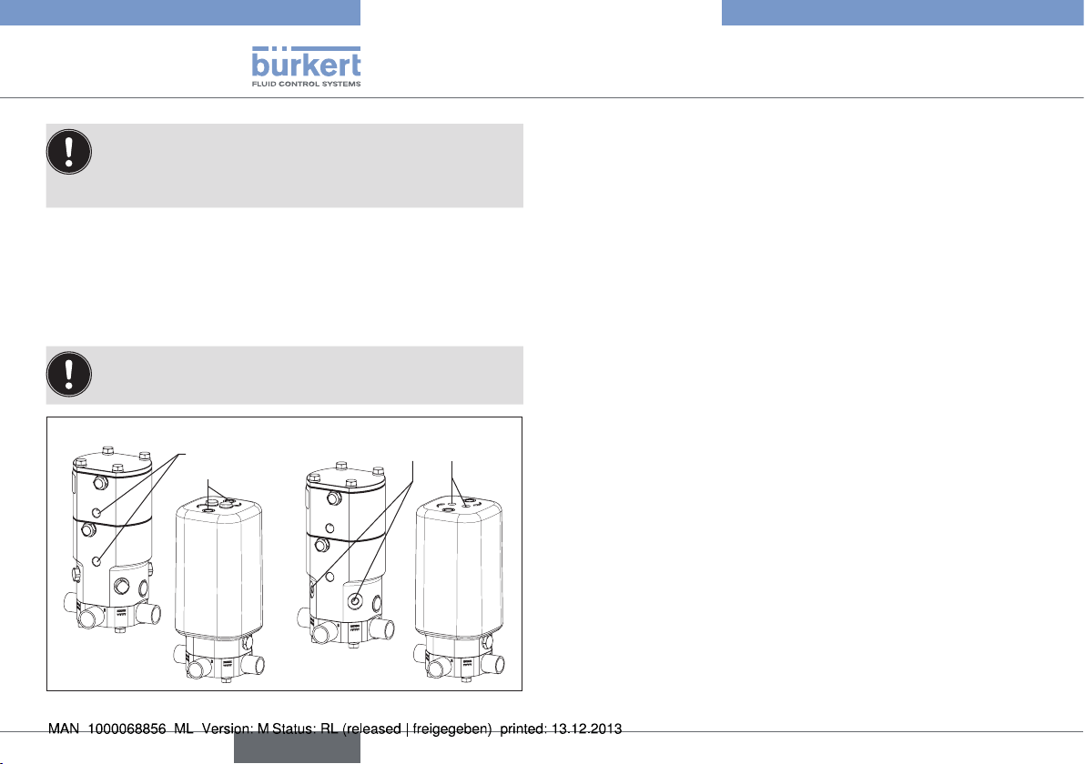
6.1. Structure of Type 2035
The diaphragm valve consists of a pneumatically operated piston
actuator, diaphragm and multi-port valve body.
Actuator cover
Silencer
Pilot air port
Actuator body
Cover position
proximity switch
Cover screw
pressure piece
Diaphragm
Valve body
Body screws / nuts
Fig. 19: Piston-controlled diaphragm valve, structure and
description
english
17
Page 18
Type 2035 / 3236
1(P)
2(A)
1(P)
2(B)
Structure and function
6.1.1. Actuator
The actuator has two actuator chambers that can be controlled
independently of each other and act on one body seat each (double
action). Where only one actuator is in operation only one actuator
chamber is equipped with the internal functional parts.
Spring force (CFA, NC) or pneumatic pilot pressure (CFB, NO)
generates the closing force of the actuator.
The force is transmitted onto the corresponding pressure piece and
the diaphragm in each case via a spindle connected to the actuator
piston.
6.1.2. Control functions (CF)
Control function A, NC (CFA)
Closed by spring force in rest
position
Control function B, NO (CFB)
Opened by spring force in rest
position
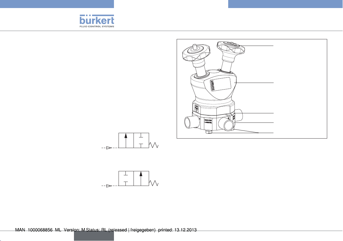
6.2. Structure of Type 3236
The diaphragm valve consists of a manually operated actuator,
diaphragm and multi-port valve body.
Hand wheel
Actuator body
Diaphragm
Valve body
Body screws
Fig. 20: Manually operated diaphragm valve, structure and
description
6.2.1. Actuator
The actuator has two hand wheels that can be controlled independently of each other and act on one body seat each (double action).
Where only one actuator is in operation only one actuator side contains functional parts.
The force is transmitted onto the corresponding pressure piece and
the diaphragm in each case via a spindle connected to the hand
wheel.
18
english
Page 19
Type 2035 / 3236
Technical Data
7. TECHNICAL DATA
7.1. Conformity
The diaphragm valves of Type 2035 and 3236 comply with EC Directives in accordance with the EC Declaration of Conformity.
7.2. Standards
The applied standards on the basis of which compliance with the EC
Directives is confirmed are listed in the EC type examination certificate
and/or the EC Declaration of Conformity.
7.3. Approvals
The product is approved for use in zone 1 and 21 in accordance
with ATEX directive 94/9/EC category 2 GD.
Observe instructions on operation in an explosion-risk (Ex)
area. See chapter "3.1. Use in Ex area".
Valve body stainless steel: EN ISO 10204 3.1
polypropylene: USP VI (material PR)
diaphragm FDA CFR 177.2600 for EPDM, FKM and silicone
FDA CFR 177.1550 for PFA
USP VI for EPDM, PFA/EPDM, silicone and PFR 91
7.4. Type label
See chapter "5.5. Valve marking".
7.5. Operating conditions
Observe permitted pressure ranges given on the type label
of the device.
Ambient temperature -10 – +60 °C
higher temperatures on request
Operating temperature max. +85 °C
Relative humidity max. 80 % (non-condensing)
7.6. Mechanical data
Dimensions see data sheet
Materials
Body material stainless steel: 1.4435/316L
(other materials on request)
PP (ultra-pure polypropylene)
PP (polypropylene USP VI)
PVDF (sterile polyvinyl-difluoride)
Diaphragm EPDM, silicone, PFA/EPDM, FKM, PFR 91
Actuator epoxy powder coated aluminum
PP body (only type 2035 RV50)
english
19
Page 20
Type 2035 / 3236
Technical Data
Connections
Port connections welded spigots DIN EN ISO 1127
(ISO 4200), DIN 11850 Series 2,
ASME BPE
SMS 3008, BS4825 (other welded connections, clamps and sterile screw fittings
on request)
Pilot air port G1/8
Surface quality interior Ra 0.5 µm passivated
exterior Ra 3.2 µm glass bead blasted
optional electro-polished
(other surface finishes on request)
Installation position any position; preferably connection B
downwards; for self-drainage see chapter
"5.3. Valve self-draining"
Service life
The service life of the device depends heavily on the conditions of use.
Especially the service life of the diaphragm depends very heavily on
the conditions of use, such as the medium, temperatures, switching
frequency, pressure etc.
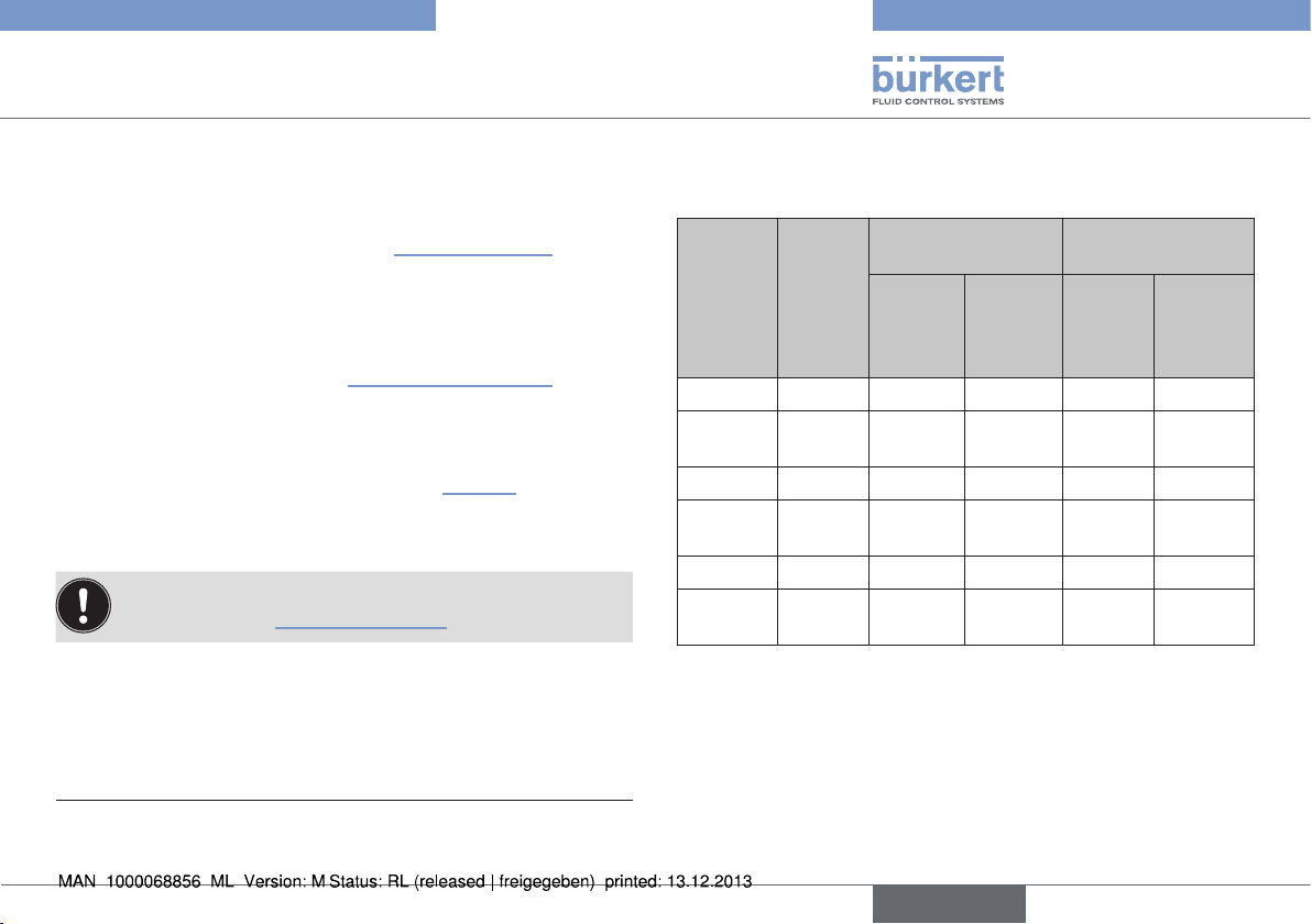
7.6.1. Diaphragm
The diaphragm seals the valve. It must be selected with care. The
choice of material should be made bearing in mind the process
medium, the temperature and the mechanical boundary conditions
(e.g. operating pressure, switching frequency etc.).
The standard materials are contained in the following table.
For conformity with FDA CFR 21 Para. 177.2600 or Para. 177.1550
and USP VI certification, see "Tab. 1: Diaphragm materials".
Diaphragm
material
EPDM peroxide-vulcanized
PFA /
EPDM
FKM fluorinated rubber acids and
silicone platinum-stabilized
PFR 91 PFR 91
Tab. 1: Diaphragm materials
Description of
material
ethylene-propylene
rubber
PFA
laminated EPDM
silicone rubber
fluorinated rubber
Use FDA USP VI
oxidizing
chemicals,
steam and hot
water
most chemicals and acids
mineral oils
aliphatic oils x x
aliphatic oils x
x x
x x
x
20
english
Page 21
Type 2035 / 3236
Technical Data
7.7. Fluidic data
Media
flow media ultra-pure, sterile, aggressive,
(see also chapter "7.6.1. Diaphragm")
Media pressure RV50 max. 8 bar
RV70/RV110 max. 6 bar
(depending on actuator, diaphragm and body
material)
see chapter "7.7.1. Pressure ranges"
Media temperature stainless steel -10 to max. +120 °C
(max. +140 °C, 30 min.)
plastic -10 to max. +40 °C
(see "Fig. 22")
PFA diaphragm 0 to max. +95 °C
Viscosity up to highly viscous
Observe instructions on operation in an explosion-risk (Ex)
area. See chapter "3.1. Use in Ex area".
Pilot medium Neutral gases, dry air (min. 10 K below min.
operating temperature), preferably unoiled
Pilot pressure
4)
6 – 10 bar (Type 2035 only)
from 4.2 bar (with reduced medium pressure)
on request
2)
7.7.1. Pressure ranges
Pilot pressure and medium pressure
EPDM, FKM,
Actuator
designation
Pilot
pressure
[bar]
Silicone, PFR 91
Static
leaktightness
[bar]
Dynamic
leaktightness
[bar]
RV50 6 – 10 8 6 8 6
RV50
EC04
4.2 – 10 6 4 6 4
RV70 6 – 10 6 4 6 4
RV70
EC04
4.2 – 10 3 2 3 2
RV110 6 – 10 6 4 6 4
RV110
EC04
4.2 – 10 3 2 3 2
Tab. 2: Static and dynamic leak-tightness
PFA / EPDM
Static
leaktightness
[bar]
Dynamic
leaktightness
[bar]
2) Pressure values [bar]: Overpressure with respect to atmospheric
pressure
english
21
Page 22
Type 2035 / 3236
Technical Data
Remarks
Static leak-tightness:
Valve is closed (diaphragm is in contact with the body seat). One
side of the body seat is under pressure. At the given pressure no
leakage takes place via the body seat.
Dynamic leak-tightness:
Valve is open and the medium is flowing through it. The downstream
flow is only slightly throttled by components placed downstream.
Both sides of the body seat are under pressure. The valve is closed
(CFA, NC via spring force; CFB, NO via pilot pressure). At the
given pressure the valve closes onto the body seat and the seal is
complete.
Static leak-tightness:
Dynamic leak-tightness:
Permitted medium pressure depending on the medium temperature
for plastic bodies.
8.0
7.0
3)
6.0
5.0
4.0
3.0
2.0
Medium pressure [bar]
1.0
0.0
0 20 40 60 80 100 120 140
PP
Temperature [°C]
PVDF
Fig. 22: Permitted medium pressure depending on the medium
temperature for plastic bodies.
Fig. 21: Static and dynamic leak-tightness
22
english
3) The given medium pressure applies for the static leak-tightness
value. For further information on this point see "Kv value".
Page 23
Type 2035 / 3236
Assembly
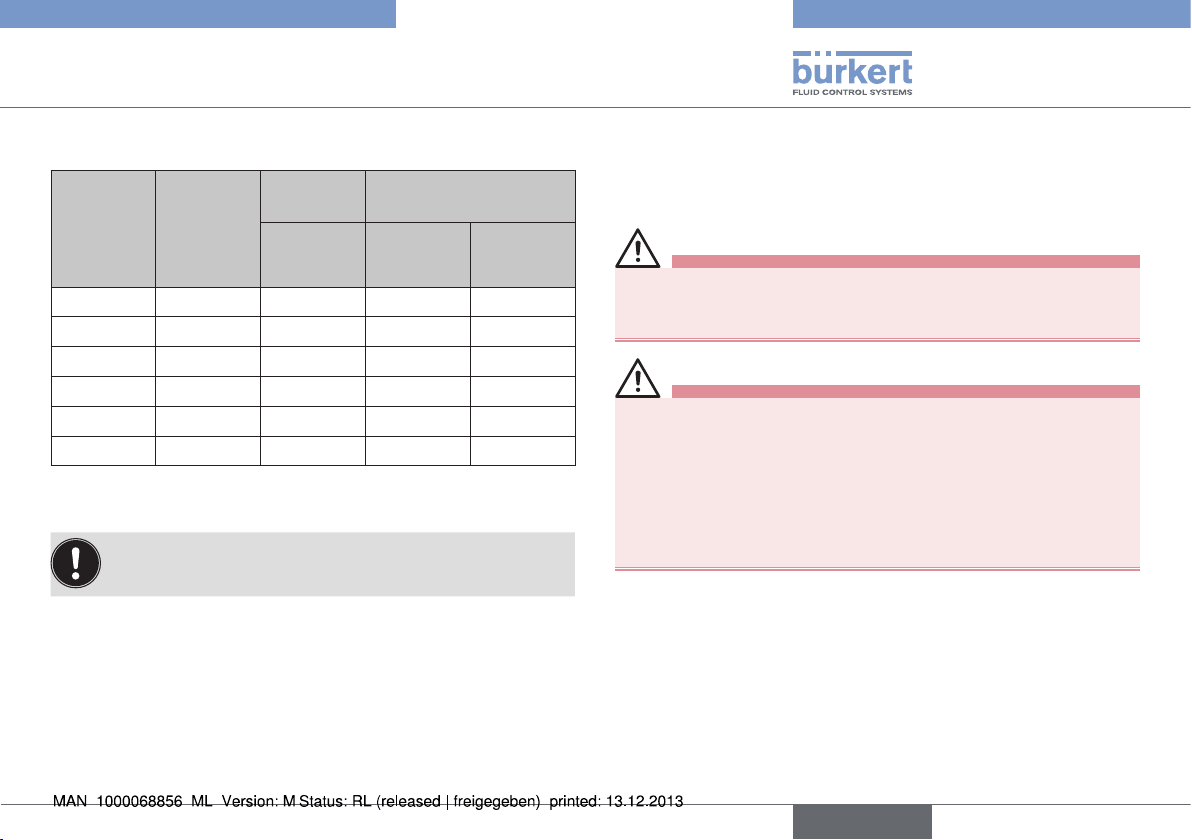
7.7.2. Kv value
Orifice
DN
Body
connection
[mm]
10 3/8" RV50 0.8 0.7
15 1/2" RV50 2.5 2
20 3/4" RV50 3.5 3.3
25 1" RV70 10 9
40 1 1/2" RV110 27 22
50 2" RV110 35 27
Tab. 3: Kv value
Valve size Actuator Kv value water [m³/h] for
diaphragm material
Designation EPDM,
FKM
All Kv values measured on valves with connections according
to ASME BPE.
PFA
8. ASSEMBLY
8.1. Safety instructions
DANGER!
Risk of injury from high pressure in the equipment/device.
▶ Before working on equipment or device, switch off the pressure
and deaerate/drain lines.
WARNING!
Risk of injury from improper assembly.
▶ Installation must only be carried out by authorized technicians and
with the appropriate tools.
Risk of injury from unintentional activation of the system and
uncontrolled restart.
▶ Secure system from unintentional activation.
▶ Following assembly, ensure a controlled restart.
8.2. Before installation
• Before connecting the valve, ensure the pipelines are flush.
• Pay attention to the flow direction.
english
23
Page 24
8.2.1. Installation position
• The piston-controlled diaphragm valve can be installed in any
position, preferably with connection B / muffler downwards.
• Installation for self-drainage of the body:
see chapter "5.3. Valve self-draining"
Type 2035 / 3236
Assembly
Silencer
8.2.2. Preparatory work
→ Clean pipelines (sealing material, swarf, etc.).
→ Support and align pipelines.
Devices with welded body
NOTE!
Damage to diaphragm or actuator.
▶ Before welding in the body disassemble the actuator and
diaphragm.
Remove the actuator from the valve body:
→ Move the actuator to the upper actuator position (CFA, NC: by
applying pilot pressure; CFB, NO: by removing the pilot pressure).
→ Mark the position of the actuator in relation to the valve body.
→ Unscrew the four body screws / nuts that connect the valve body
with the actuator. Remove the actuator and the diaphragm.
24
english
Actuator
Diaphragm
Valve body
Body screws and
washers
Fig. 23: Assembly
8.3. Installation
8.3.1. Installing the body
Welded body
→ Weld valve body in pipeline system.
Other body designs
→ Connect body to pipeline.
Page 25
Type 2035 / 3236
Assembly
8.3.2. Installing the actuator (welded body)
→ Move the actuator to the upper actuator position (CFA, NC: by
applying pilot pressure; CFB, NO: by removing the pilot pressure).
→ Put the actuator / diaphragm on the body with correct alignment
(so that the markings made previously align).
→ Tighten the diagonally opposed body screws / nuts until there
is visible, uniform mechanical contact between the valve body,
diaphragm and actuator.
→ Tighten the diagonally opposed body screws / nuts twice with a
quarter turn and using the same torque in each case.
8.3.3. Test for leak-tightness / valve
function
WARNING!
Danger of injury through egress of flow medium.
▶ Tighten the body screws sufficiently.
Applying an unnecessary degree of force to tighten the body
screws / nuts leads to increased wear and therefore shortens
the service life of the diaphragm.
If the valve leaks when the medium pressure rises:
→ Tighten the diagonally opposed body screws / nuts by a one-
eighth turn until the valve no longer leaks.
This procedure ensures that the diaphragm and the pressure piece
are optimally aligned to each other and the valve function is ensured.
8.4. Pneumatic connection
(Type 2035 only)
DANGER!
Risk of injury from high pressure in the equipment/device.
▶ Before working on equipment or device, switch off the pressure
and deaerate/drain lines.
WARNING!
Risk of injury from unsuitable connection hoses.
Hoses which cannot withstand the pressure and temperature
range may result in hazardous situations.
▶ Use only hoses which are authorized for the indicated pressure
and temperature range.
▶ Observe the data sheet specifications from the hose manufacturers.
8.4.1. Connection of the pilot medium
For the assignment of pilot air ports refer to the installation and dimensional drawing included with delivery of the valve. Compare also the
information given in chapter "6. Structure and function".
The use of pneumatic hose with a minimum size of 6/4 is recommended.
For longer hose lengths the hose cross-sections should be adapted
accordingly.
english
25
Page 26
Type 2035 / 3236
Assembly
In aggressive surroundings and in situations where moisture
could enter the actuator via the exhaust air port or muffler
the exhaust air should be collected and ducted to a noncritical location.
Procedure:
→ Remove the yellow protective stopper.
→ Connect the pilot medium to the pilot air port with the aid of the
installation and dimensional drawing supplied.
Control function B:
The pilot pressure should be selected to be as low as possible to reduce wear on the diaphragm.
Pilot air
ports
Fig. 24: Pneumatic connection; installation of a proximity switch
Connections for
proximity sensors
8.5. Installation of the inductive
proximity switch
The switch is installed using the M8 x 1 or M12 x 1 thread on the
side of the actuator (for RV50 with PP cover on the upper side).
→ Connect with the aid of the installation and dimensional drawing
supplied.
→ Remove the yellow protective stopper.
→ Move the actuator to the position that is to be queried by the
proximity switch:
RV50/70:
lower proximity switch: Move the actuator to the lower actuator
position (CFA, NC: by removing pilot pressure; CFB, NO: by
applying the pilot pressure).
upper proximity switch: Move the actuator to the upper actuator
position (CFA, NC: by applying pilot pressure; CFB, NO: by
removing the pilot pressure).
RV110:
Move the actuator to the lower actuator position (CFA, NC:
by removing pilot pressure; CFB, NO: by applying the pilot
pressure).
→ Screw in the proximity switches until they connect with the pressure
pieces.
→ Then unscrew the proximity switches by one half to one turn.
→ Secure the proximity switches with the aid of securing nuts (the
second nut and the two washers supplied are not needed).
→ Test the functionality of the proximity switches.
26
english
Page 27
Type 2035 / 3236
Operation and function
NOTE!
Ingress of moisture and dirt.
▶ If no proximity switch is used, block the M8 x 1 or M12 x 1 threaded
connection.
9. OPERATION AND FUNCTION
9.1. Safety instructions
WARNING!
Danger due to improper operation.
Improper operation may result in injuries as well as damage to the
device and the area around it.
▶ The operating personnel must know and have understood the
contents of the operating instructions.
▶ Observe the safety instructions and intended use.
▶ Only adequately trained personnel may operate the equipment/
the device.
9.2. Type 2035 - pneumatic operation
The diaphragm valve is controlled by compressed air. The compressed air reaches the pistons via the pilot air ports and actuates
them. This causes the valves to open or close.
For the assignment of pilot air ports refer to the installation
and dimensional drawing included with delivery of the valve.
english
27
Page 28
Type 2035 / 3236
Electrical pre-controller
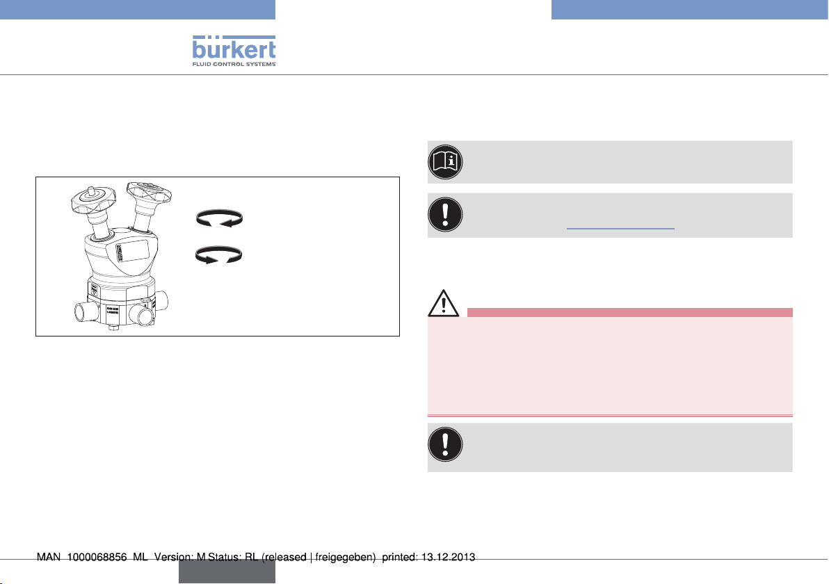
9.3. Type 3236 - manual operation
The diaphragm valve is actuated by means of hand wheels.
Close valve seat Turn clockwise
Open valve seat Turn counter-clockwise
Close valve seat
Open valve seat
Fig. 25: Type 3236
10. ELECTRICAL
PRE-CONTROLLER
The electrical connection of the pilot valve is described in
the operating instructions for the pilot valve.
Observe instructions on operation in an explosion-risk (Ex)
area. See chapter "3.1. Use in Ex area".
11. DISASSEMBLY
DANGER!
Risk of injury from discharge of medium and release of
pressure.
It is dangerous to remove a device which is under pressure due to
the sudden release of pressure or discharge of medium.
▶ Before removing a device, switch off the pressure and vent the
lines.
If the valve is to be reused after removal, the actuator must
be removed before disassembly where welded bodies are
involved. For this, refer to the assembly instructions.
Procedure:
→ Loosen pneumatic connection.
→ Remove device.
28
english
Page 29
Type 2035 / 3236
Maintenance, Cleaning
12. MAINTENANCE, CLEANING
12.1. Safety instructions
DANGER!
Risk of injury from high pressure in the equipment/device.
▶ Before working on equipment or device, switch off the pressure
and deaerate/drain lines.
Risk of electric shock.
▶ Before working on equipment or device, switch off the power
supply and secure to prevent reactivation.
▶ Observe applicable accident prevention and safety regulations
for electrical equipment.
WARNING!
Risk of injury from improper maintenance.
▶ Installation must only be carried out by authorized technicians and
with the appropriate tools!
Risk of injury from unintentional activation of the system and
uncontrolled restart.
▶ Secure system from unintentional activation.
▶ Following maintenance, ensure a controlled restart.
12.2. Servicing intervals
Check the diaphragm valves regularly for proper operation in terms
of assembly, installation and operation. Take the following factors into
account when planning servicing intervals:
• Operational conditions (amount of usage, improper usage),
• Manufacturer's specifications in the technical documentation (e.g.
mechanical service life,
• major system modifications.
12.3. Servicing work
During servicing, check:
• that hoses are secure
• plastic bodies for signs of alteration
• that permissible temperature ranges are adhered to (see Technical
Specifications)
• proper functionality
12.3.1. Actuator
The actuator of the diaphragm valve is maintenance-free provided it
is used according to these operating instructions.
english
29
Page 30
Type 2035 / 3236
Maintenance, Cleaning
12.3.2. Wearing parts of the diaphragm valve
The diaphragm is subject to wear.
→ If leakage occurs replace the diaphragm. (see chapter "13. Repairs").
A bulging diaphragm may reduce the flow rate.
The replacement of the diaphragm is described in chapter
"13. Repairs".
12.4. Cleaning
NOTE!
Avoid causing damage with cleaning agents.
▶ Before cleaning, check that the cleaning agents are compatible
with the device materials.
Epoxy powder coatings will be attacked by unsuitable
cleaning agents.
▶ Clean the surface with a cleaning agent suitable for this material,
e.g. with 25% alcohol or acetone.
Observe instructions on operation in an explosion-risk (Ex)
area. See chapter "3.1. Use in Ex area".
Actuator
Clean the actuator surface using a moist cloth. Only use cleaning
agents that do not attack the actuator surface.
The following actuator versions are available:
Actuator material (attribute AM):
AM = AE: Actuator body made of epoxy coated aluminium
AM = AP: Actuator cover made of polypropylene (PP)
AM = AE and
VAR = NC31: Actuator body made of aluminium
Body / Diaphragm
The bodies are suitable for CIP. Clean the valves using cleaning
agents that do not attack the body and diaphragm materials. Avoid
cleaning agents with high pH values.
30
english
Page 31

Type 2035 / 3236
Repairs
13. REPAIRS
13.1. Safety instructions
DANGER!
Risk of injury from high pressure in the equipment/device.
▶ Before working on equipment or device, switch off the pressure
and deaerate/drain lines.
Risk of electric shock.
▶ Before working on equipment or device, switch off the power
supply and secure to prevent reactivation.
▶ Observe applicable accident prevention and safety regulations
for electrical equipment.
WARNING!
Risk of injury from improper repair.
▶ Installation must only be carried out by authorized technicians and
with the appropriate tools.
▶ Observe the tightening torques.
▶ On completion of the work check valve for leaks and function.
Risk of injury from unintentional activation of the system and
uncontrolled restart.
▶ Secure system from unintentional activation.
▶ Following maintenance, ensure a controlled restart.
13.2. Replacing the diaphragm
On signs of wear or on adaptation of the valves to changed conditions
of use it may be necessary to replace the diaphragm.
The procedure in each case is described below according to the
actuator type and the valve body material.
Required spare part
• Diaphragm
13.2.1. RV50, RV70 and RV110
manually operated / double action
WARNING!
Danger of injury due to flow medium, operating pressure and
movable parts.
▶ Before disassembly, make sure that the valve is not under pressure
and completely drained.
▶ Wear protective clothing.
english
31
Page 32

Type 2035 / 3236
Repairs
Disassembly of the actuator and diaphragm
→ Mark the position of the actuator in relation to the valve body.
→ Unscrew the four body screws / nuts that connect the valve body
1
with the actuator. Remove the valve body
→ Turn the hand wheels to the Closed position
further).
.
2
(never turn
→ Take out the pressure pieces downwards from the actuator
→ Take the diaphragm out of the pressure pieces sideways
Hand wheel
2
4
1
3
Body screws
Fig. 26: Disassembly of manually operated double actuator
Pressure pieces Diaphragm
Assembly of actuator and diaphragm
→ Insert the diaphragm into the T-guide of the pressure pieces
→ Insert the pressure pieces into the actuator
→ Turn the hand wheels to the Open position
6
.
7
.
5
.
→ Put the actuator / diaphragm on the body with correct alignment
3
.
4
.
(so that the markings made previously align).
→ Tighten the diagonally opposed body screws / nuts until there
is visible, uniform mechanical contact between the valve body,
diaphragm and actuator
8
.
→ Tighten the diagonally opposed body screws / nuts twice with a
quarter turn and using the same torque in each case.
Hand wheel
7
5
Diaphragm
6
Pressure pieces
Body screws
8
32
Fig. 27: Assembly of manually operated double actuator
english
Page 33

Type 2035 / 3236
Repairs
Test for leak-tightness / valve function
WARNING!
Danger of injury through egress of flow medium.
▶ Tighten the body screws / nuts sufficiently.
Applying an unnecessary degree of force to tighten the
body screws / nuts leads to increased wear and therefore
shortens the service life of the diaphragm.
If the valve leaks when the medium pressure rises:
→ Tighten the diagonally opposed body screws / nuts by a one-
eighth turn until the valve no longer leaks.
This procedure ensures that the diaphragm and the pressure pieces
are optimally aligned to each other and the valve function is ensured.
13.2.2. RV50, RV70 and RV110 manually
operated / single action
WARNING!
Danger of injury due to flow medium, operating pressure and
movable parts.
▶ Before disassembly, make sure that the valve is not under pressure
and completely drained.
▶ Wear protective clothing.
Disassembly of the actuator and diaphragm
→ Mark the position of the actuator in relation to the valve body.
→ Unscrew the screw (for RV50 Allen-type, for RV70/RV110 hex-
1
agonal) on the side of the actuator
.
→ Unscrew the four body screws / nuts that connect the valve body
2
with the actuator
→ Turn the hand wheel to the Closed position
. Remove the valve body.
3
.
→ At the diaphragm, take the pressure pieces out of the actuator
→ Take the diaphragm out of the pressure pieces sideways
Hand wheel
3
5
1
2
4
Screw
Fig. 28: Disassembly of manually operated single actuator
Body screws
Pressure pieces Diaphragm
4
.
5
.
english
33
Page 34

Type 2035 / 3236
Repairs
Assembly of actuator and diaphragm
6
Diaphragm
9
10
Screw
Fig. 29: Assembly of manually operated single actuator
7
Pressure pieces
11
Hand wheel
Body screws
→ Insert the diaphragm into the T-guide of the pressure pieces
→ Insert the pressure piece into the actuator
the following: The thread of the pressure piece spindle and the
hand wheel spindle must engage with each other
→ Turn the hand wheel to the Open position
7
. <Pay attention to
8
.
9
.
→ Position and tighten the screw (for RV50 Allen-type, for RV70/
10
8
RV110 hexagonal) on the side of the actuator
.
→ Put the actuator / diaphragm on the body with correct alignment
(so that the markings made previously align).
→ Tighten the diagonally opposed body screws / nuts until there
is visible, uniform mechanical contact between the valve body,
diaphragm and actuator
11
.
→ Tighten the diagonally opposed body screws / nuts twice with a
quarter turn and using the same torque in each case.
Test for leak-tightness / valve function
WARNING!
Danger of injury through egress of flow medium.
▶ Tighten the body screws / nuts sufficiently.
Applying an unnecessary degree of force to tighten the
body screws / nuts leads to increased wear and therefore
shortens the service life of the diaphragm.
If the valve leaks when the medium pressure rises:
→ Tighten the diagonally opposed body screws / nuts by a one-
6
.
eighth turn until the valve no longer leaks.
This procedure ensures that the diaphragm and the pressure piece
are optimally aligned to each other and the valve function is ensured.
34
english
Page 35
Type 2035 / 3236
Repairs
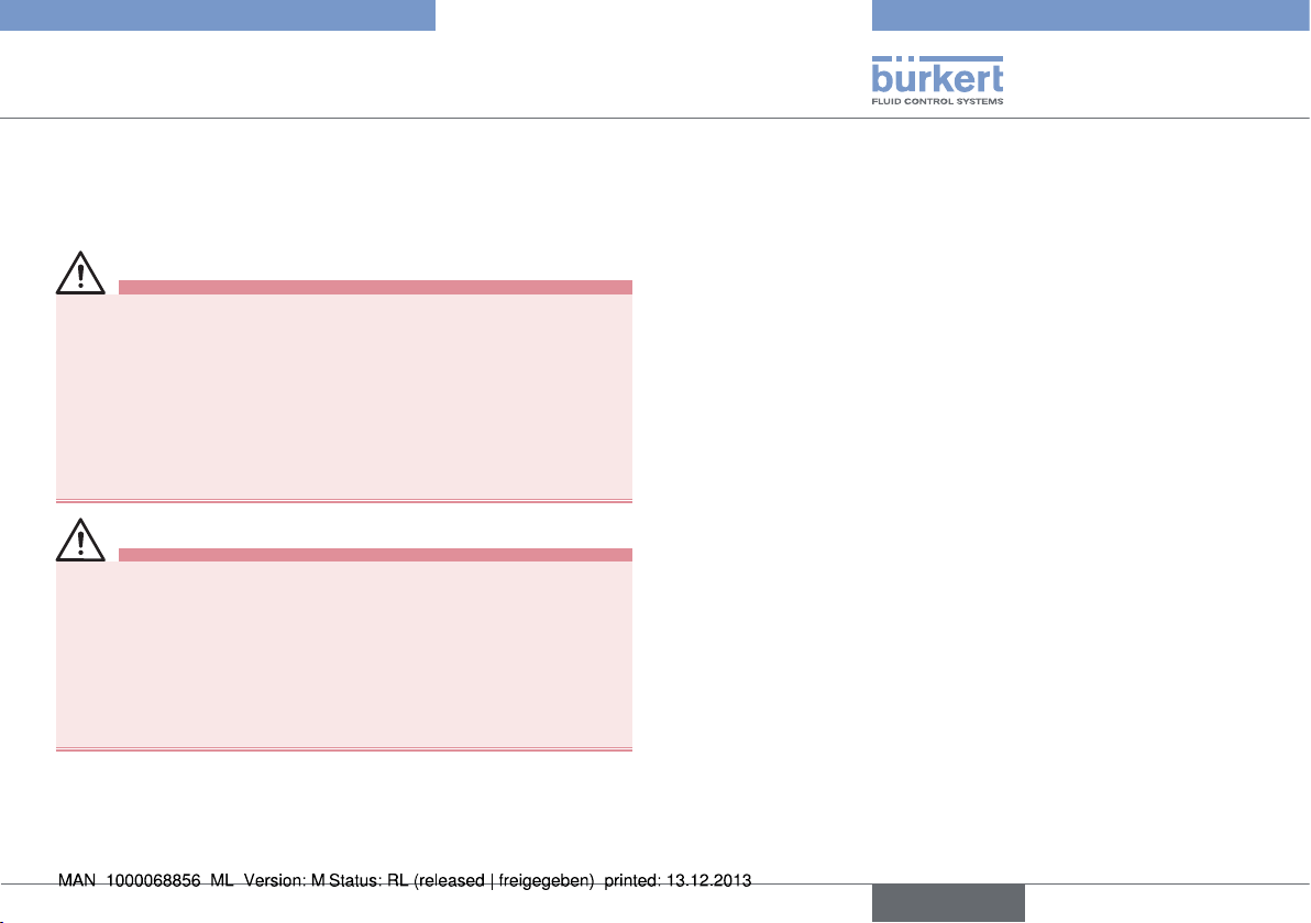
13.2.3. RV50 and RV70 pneumatic actuation
WARNING!
Danger of injury due to flow medium, operating pressure and
movable parts.
▶ Before disassembly, make sure that the valve is not under pressure
and completely drained.
▶ Wear protective clothing.
Risk of injury when opening the actuator.
The actuator contains tensioned springs. If the actuator is opened,
injuries may be caused by the springs jumping out.
▶ The actuator must not be opened.
Disassembly of the actuator and diaphragm
→ Move the actuator to the upper actuator position (CFA, NC, NC: by
applying pilot pressure; CFB, NO: by removing the pilot pressure).
→ Mark the position of the actuator in relation to the valve body.
→ Unscrew the four body screws / nuts that connect the valve body
1
with the actuator. Remove the valve body
.
→ Remove the covers (for RV50 with PP cover: muffler and screw)
→ Loosen the setscrew on the pressure pieces
3
.
→ At the diaphragm, take the pressure pieces out of the actuator
4
downwards
→ Take the diaphragm out of the pressure pieces sideways
.
5
.
2
1
Body screws
Fig. 30: Disassembly of the RV50, RV70 pneumatic actuators
2
.
Pressure pieces Diaphragm
4
3
Setscrew
5
english
35
Page 36

Type 2035 / 3236
Repairs
Assembly of actuator and diaphragm
CAUTION!
Danger of injury due to movable parts in the actuator.
▶ When applying or removing the pilot pressure on the actuator
keep members and other objects away from the actuator openings.
→ Insert the diaphragm into the T-guide of the pressure pieces
7
Make sure that the four spacing sleeves are installed
(RV70 only).
For easier assembly of the pressure pieces the actuator
spindles should be in the lower position (Close) (CFA, NC:
by removing the pilot pressure; CFB, NO: by applying the
pilot pressure).
→ Insert the pressure pieces into the actuator
the actuator spindles are fully inserted into the corresponding
recesses of the pressure pieces
9
.
→ Tighten the setscrews on the pressure pieces
8
. Make sure that
10
.
→ Close the covers (for RV50 with PP cover: muffler and screw)
→ Move the actuator to the upper actuator position (CFA, NC: by
applying pilot pressure; CFB, NO: by removing the pilot pressure).
→ Put the actuator / diaphragm on the body with correct alignment
(so that the markings made previously align).
→ Tighten the diagonally opposed body screws / nuts until there
is visible, uniform mechanical contact between the valve body,
diaphragm and actuator
12
.
→ Tighten the diagonally opposed body screws / nuts twice with a
quarter turn and using the same torque in each case.
→ CFA, NC actuators: Remove the pilot pressure.
6
.
6
11
Diaphragm
Spacer sleeve
11
.
Fig. 31: Assembly of the RV50, RV70 pneumatic actuators
7
Actuator spindles
8
10
Setscrew
12
Body screwsPressure pieces
9
36
english
Page 37

Type 2035 / 3236
Repairs
Test for leak-tightness / valve function
WARNING!
Danger of injury through egress of flow medium.
▶ Tighten the body screws / nuts sufficiently.
Applying an unnecessary degree of force to tighten the
body screws / nuts leads to increased wear and therefore
shortens the service life of the diaphragm.
If the valve leaks when the medium pressure rises:
→ Tighten the diagonally opposed body screws / nuts by a one-
eighth turn until the valve no longer leaks.
This procedure ensures that the diaphragm and the pressure pieces
are optimally aligned to each other and the valve function is ensured.
→ Switch the valve several times and if necessary tighten the body
screws / nuts more.
13.2.4. RV110 actuator
WARNING!
Danger of injury due to flow medium, operating pressure and
movable parts.
▶ Before disassembly, make sure that the valve is not under pressure
and completely drained.
▶ Wear protective clothing.
Risk of injury when opening the actuator body.
The actuator contains tensioned springs. If the actuator body is
opened, injuries may be caused by the springs jumping out.
▶ The actuator body must not be opened.
Disassembly of the actuator and diaphragm
→ Mark the position of the actuator in relation to the valve body.
→ Move the actuator to the upper actuator position (CFA, NC: by
applying pilot pressure; CFB, NO, NO: by removing the pilot
pressure).
→ Unscrew the four body screws / nuts that connect the valve body
1
with the actuator. Remove the valve body
→ Loosen and remove the guide bolt
2
→ Turn the diaphragm and pressure pieces through 45°
4
take them out
.
→ Take the diaphragm out of the pressure pieces sideways
.
.
3
and
5
.
english
37
Page 38

Type 2035 / 3236
Repairs
For easier assembly of the pressure pieces the actuator
spindles should be in the lower position (Close) (CFA, NC:
by removing the pilot pressure; CFB, NO: by applying the
pilot pressure).
1
Guide bolt
2
Fig. 32: Disassembly of the RV110 pneumatic actuator
Assembly of actuator and diaphragm
CAUTION!
Danger of injury due to movable parts in the actuator.
▶ When applying or removing the pilot pressure on the actuator
keep members and other objects away from the actuator openings.
3
45°
Pressure
pieces
4
Diaphragm
5
→ Insert the diaphragm into the T-guide of the pressure pieces
7
Make sure that the four spacing sleeves are installed
38
english
.
→ Insert the pressure pieces into the actuator
the actuator spindles are fully inserted into the corresponding
recesses of the pressure pieces
NOTE!
Damage to diaphragm and valve malfunction.
▶ Turn the diaphragm and pressure pieces only far enough to align
the screw holes of the actuator and the diaphragm.
9
.
8
. Make sure that
→ Turn the diaphragm and pressure piece no more than 45° until
10
the holes of the diaphragm line up with those of the actuator
.
→ Screw in the guide bolt and tighten with a torque of approx.
11
10 Nm
.
→ Move the actuator to the upper actuator position (CFA, NC: by
applying pilot pressure; CFB, NO: by removing the pilot pressure).
→ Put the actuator / diaphragm on the body with correct alignment
12
(so that the markings made previously align).
→ Tighten the diagonally opposed body screws / nuts until there
is visible, uniform mechanical contact between the valve body,
diaphragm and actuator.
→ Tighten the diagonally opposed body screws / nuts twice with a
6
.
quarter turn and using the same torque in each case.
Page 39

Type 2035 / 3236
Repairs
Pressure pieces
45°
10
Fig. 33: Assembly of the RV110 pneumatic actuator
Diaphragm
6
7
Spacer sleeve
Guide bolt
11
8
Actuator spindles
Diaphragm
12
9
Pressure pieces
Test for leak-tightness / valve function
WARNING!
Danger of injury through egress of flow medium.
▶ Tighten the body screws / nuts sufficiently.
Applying an unnecessary degree of force to tighten the
body screws / nuts leads to increased wear and therefore
shortens the service life of the diaphragm.
If the valve leaks when the medium pressure rises:
→ Tighten the diagonally opposed body screws / nuts by a one-
eighth turn until the valve no longer leaks.
This procedure ensures that the diaphragm and the pressure piece
are optimally aligned to each other and the valve function is ensured.
→ Switch the valve several times and if necessary tighten the body
screws / nuts more.
english
39
Page 40

Type 2035 / 3236
Spare parts
14. SPARE PARTS
WARNING
Risk of injury when opening the actuator.
The actuator contains a tensioned spring. If the actuator is opened,
there is a risk of injury because the spring may jump out.
▶ The actuator must not be opened.
CAUTION!
Risk of injury and/or damage by the use of incorrect parts.
Incorrect accessories and unsuitable spare parts may cause injuries
and damage the device and the surrounding area.
▶ Use original accessories and original spare parts from Bürkert only.
The diaphragm is available as a spare part for the diaphragm valve
Type 2035 / 3236.
If you have any queries, please contact your Bürkert sales
office.
14.1. Order table
Size Order numbers for diaphragms
EPDM
Code AB
RV50 207334 207338 207352
RV70 207339 207341 207350
RV110 207344 207345 207349
Tab. 4: Diaphragm ordering table
Other diaphragms on request.
PFA/EPDM
Code PN
EPDM
customized
Code AC
40
english
Page 41

Type 2035 / 3236
Malfunctions
15. MALFUNCTIONS
Malfunction Cause / remedial action
Actuator does
not switch.
Valve is not
sealed.
Flow rate
reduced.
Tab. 5: Malfunctions
4) see "Fig. 24: Pneumatic connection; installation of a proximity
switch".
Pilot air port interchanged
Check pilot air ports
Pilot pressure too low
See pressure specifications on the type label.
Medium pressure too high
See pressure specifications on the type label.
Medium pressure too high
See pressure specifications on the type label.
Pilot pressure too low
See pressure specifications on the type label.
Diaphragm bulging
→ Replace diaphragm.
4)
16. TRANSPORT, STORAGE,
PACKAGING
NOTE!
Transport damage.
Inadequately protected devices may be damaged during
transportation.
▶ Protect the device against moisture and dirt in shock-resistant
packaging during transportation.
▶ Prevent the temperature from exceeding or dropping below the
permitted storage temperature.
▶ Protect the pneumatic connections from damage by placing pro-
tective caps on them.
Incorrect storage may damage the device.
▶ Store the device in a dry and dust-free location!
▶ Storage temperature 0 – +60 °C.
If the device is stored with tightened body screws, the diaphragm may be permanently deformed.
▶ If the device is stored for a prolonged period, slacken the body
screws.
Damage to the environment caused by device components
contaminated with media.
▶ Ensure that the device and packaging are disposed of in an envi-
ronmentally sound manner.
▶ Observe applicable disposal and environmental regulations.
english
41
Page 42

Type 2035 / 3236
42
english
Page 43

Typ 2035 / 3236
Inhaltsverzeichnis
1. DIE BEDIENUNGSANLEITUNG ............................................................45
1.1. Darstellungsmittel ...........................................................................45
1.2. Begriffsdefinition / Abkürzung .....................................................45
2. BESTIMMUNGSGEMÄSSE VERWENDUNG ...................................46
2.1. Beschränkungen ............................................................................46
3. GRUNDLEGENDE SICHERHEITSHINWEISE ................................. 46
3.1. Hinweise für den Einsatz im Ex-Bereich ...................................47
3.2. Besondere Bedingungen .............................................................49
4. ALLGEMEINE HINWEISE .......................................................................... 49
4.1. Kontaktadresse ...............................................................................49
4.2. Gewährleistung...............................................................................49
4.3. Informationen im Internet ..............................................................49
4.4. Warenzeichen .................................................................................50
5. PRODUKTBESCHREIBUNG ................................................................... 50
5.1. Allgemeine Beschreibung ............................................................50
5.2. Gerätevarianten ..............................................................................50
5.3. Selbstentleerung der Ventile .......................................................52
5.4. Ventilsymbole und Fließbilder ......................................................53
5.5. Ventilkennzeichnung ......................................................................55
5.6. Vorgesehener Einsatzbereich ......................................................57
6. AUFBAU UND FUNKTION ....................................................................... 57
6.1. Aufbau Typ 2035 ............................................................................57
6.2. Aufbau Typ 3236 ............................................................................58
7. TECHNISCHE DATEN ................................................................................ 59
7.1. Konformität .......................................................................................59
7.2. Normen .............................................................................................59
7.3. Zulassungen ....................................................................................59
7.4. Typschild ..........................................................................................59
7.5. Betriebsbedingungen ....................................................................59
7.6. Mechanische Daten .......................................................................59
7.7. Fluidische Daten .............................................................................61
7.8. Sicherheitshinweise .......................................................................63
7.9. Vor dem Einbau ..............................................................................63
7.10. Einbau .............................................................................................64
7.11. Pneumatischer Anschluss (nur Typ 2035) .............................65
7.12. Einbau des induktiven Näherungsschalters ...........................66
8. BEDIENUNG UND FUNKTION .............................................................. 67
8.1. Sicherheitshinweise .......................................................................67
8.2. Typ 2035 - Pneumatische Betätigung ......................................67
8.3. Typ 3236 - Manuelle Betätigung ................................................68
9. ELEKTRISCHE VORSTEUERUNG .......................................................68
10. DEMONTAGE ............................................................................................... 68
11. WARTUNG, REINIGUNG ......................................................................... 69
11.1. Sicherheitshinweise.....................................................................69
11.2. Wartungsintervalle .......................................................................69
11.3. Wartungsarbeiten ........................................................................69
11.4. Reinigung .......................................................................................70
deutsch
43
Page 44

12. INSTANDHALTUNG ...................................................................................71
12.1. Sicherheitshinweise.....................................................................71
12.2. Austausch der Membran ............................................................71
13. ERSATZTEILE ...............................................................................................80
13.1. Bestelltabelle.................................................................................80
14. STÖRUNGEN ................................................................................................81
15. TRANSPORT, LAGERUNG, VERPACKUNG ..................................81
Typ 2035 / 3236
44
deutsch
Page 45

Typ 2035 / 3236
Die Bedienungsanleitung
1. DIE BEDIENUNGSANLEITUNG
Die Bedienungsanleitung beschreibt den gesamten Lebenszyklus
des Geräts. Bewahren Sie diese Anleitung so auf, dass sie für jeden
Benutzer gut zugänglich ist und jedem neuen Eigentümer des Geräts
wieder zur Verfügung steht.
WARNUNG!
Die Bedienungsanleitung enthält wichtige Informationen zur
Sicherheit.
Das Nichtbeachten dieser Hinweise kann zu gefährlichen Situationen
führen.
▶ Die Bedienungsanleitung muss gelesen und verstanden werden.
1.1. Darstellungsmittel
GEFAHR!
Warnt vor einer unmittelbaren Gefahr.
▶ Bei Nichtbeachtung sind Tod oder schwere Verletzungen die Folge.
WARNUNG!
Warnt vor einer möglicherweise gefährlichen Situation.
▶ Bei Nichtbeachtung drohen schwere Verletzungen oder Tod.
VORSICHT!
Warnt vor einer möglichen Gefährdung.
▶ Nichtbeachtung kann mittelschwere oder leichte Verletzungen
zur Folge haben.
HINWEIS!
Warnt vor Sachschäden.
▶ Bei Nichtbeachtung kann das Gerät oder die Anlage beschädigt
werden.
bezeichnet wichtige Zusatzinformationen, Tipps und
Empfehlungen.
verweist auf Informationen in dieser Bedienungsanleitung
oder in anderen Dokumentationen.
▶ markiert eine Anweisung zur Gefahrenvermeidung.
→ markiert einen Arbeitsschritt, den Sie ausführen müssen.
1.2. Begriffsdefinition / Abkürzung
Der in dieser Anleitung verwendete Begriff „Gerät“ steht immer für
das Robolux-Mehrwege-Membranventil Typ 2035 / 3236.
Der in dieser Anleitung verwendeten Begriff „Membranventil“ steht
immer für das Robolux-Mehrwege-Membranventil Typ 2035 / 3236.
Die in dieser Anleitung verwendete Abkürzung „Ex“
steht immer für „explosionsgefährdet“.
deutsch
45
Page 46

Typ 2035 / 3236
Bestimmungsgemäße Verwendung
2. BESTIMMUNGSGEMÄSSE
VERWENDUNG
Bei nicht bestimmungsgemäßer Verwendung des RoboluxMehrwege-Membranventils Typ 2035 / 3236 können Gefahren
für Personen, Anlagen in der Umgebung und die Umwelt
entstehen.
Das Gerät ist für die Steuerung des Durchflusses von flüssigen
Medien konzipiert.
▶ Für den Einsatz sind die in den Vertragsdokumenten, der Bedie-
nungsanleitung und auf dem Typschild spezifizierten zulässigen
Daten, Betriebs- und Einsatzbedingungen zu beachten. Die vorgesehenen Einsatzfälle sind im Kapitel „5. Produktbeschreibung“
aufgeführt.
▶ Gerät nur in Verbindung mit von Bürkert empfohlenen bzw. zuge-
lassenen Fremdgeräten und -komponenten einsetzen.
▶ Voraussetzungen für den sicheren und einwandfreien Betrieb sind
sachgemäßer Transport, sachgemäße Lagerung und Installation
sowie sorgfältige Bedienung und Instandhaltung.
▶ Gerät nur bestimmungsgemäß verwenden.
2.1. Beschränkungen
Beachten Sie bei der Ausfuhr des Systems/Geräts gegebenenfalls
bestehende Beschränkungen.
3. GRUNDLEGENDE
SICHERHEITSHINWEISE
Diese Sicherheitshinweise berücksichtigen keine
• Zufälligkeiten und Ereignisse, die bei Montage, Betrieb und Wartung
der Geräte auftreten können.
• ortsbezogenen Sicherheitsbestimmungen, für deren Einhaltung, auch
in Bezug auf das Montagepersonal, der Betreiber verantwortlich ist.
GEFAHR!
Verletzungsgefahr durch hohen Druck in Anlage/Gerät.
▶ Vor Arbeiten an Anlage oder Gerät, den Druck abschalten und
Leitungen entlüften/entleeren.
Gefahr durch Stromschlag.
▶ Vor Arbeiten an Anlage oder Gerät, die Spannung abschalten und
vor Wiedereinschalten sichern.
▶ Die geltenden Unfallverhütungs- und Sicherheitsbestimmungen
für elektrische Geräte beachten.
WARNUNG!
Verletzungsgefahr beim Öffnen des Antriebs.
Der Antrieb enthält gespannte Federn. Beim Öffnen des Antriebs
kann es durch herausspringende Federn zu Verletzungen kommen.
▶ Der Antrieb darf nicht geöffnet werden.
46
deutsch
Page 47

Typ 2035 / 3236
Grundlegende Sicherheitshinweise
VORSICHT!
Verbrennungsgefahr.
Bei Dauerbetrieb kann die Geräteoberfläche heiß werden.
▶ Das Gerät nicht mit bloßen Händen berühren.
Allgemeine Gefahrensituationen.
Zum Schutz vor Verletzungen ist zu beachten:
▶ Dass die Anlage nicht unbeabsichtigt betätigt werden kann.
▶ Installations- und Instandhaltungsarbeiten dürfen nur von auto-
risiertem Fachpersonal mit geeignetem Werkzeug ausgeführt
werden.
▶ Nach einer Unterbrechung der elektrischen oder pneumatischen
Versorgung ist ein definierter oder kontrollierter Wiederanlauf des
Prozesses zu gewährleisten.
▶ Das Gerät darf nur in einwandfreiem Zustand und unter Beachtung
der Bedienungsanleitung betrieben werden.
▶ Für die Einsatzplanung und den Betrieb des Geräts müssen die
allgemeinen Regeln der Technik eingehalten werden.
Zum Schutz vor Sachbeschädigungen ist zu beachten:
▶ In die Medienanschlüsse nur Medien einspeisen, die im Kapitel „7.
Technische Daten“ als Durchflussmedien aufgeführt sind.
▶ Ventil nicht mechanisch belasten (z. B. durch Ablage von Gegen-
ständen oder als Trittstufe).
▶ Keine äußerlichen Veränderungen an den Ventilen vornehmen.
Gehäuseteile und Schrauben nicht lackieren.
3.1. Hinweise für den Einsatz
im Ex-Bereich
Abkürzung „Ex“: siehe Kapitel „1.2. Begriffsdefinition / Abkürzung“.
3.1.1. Sicherheitshinweise
Bei Einsatz im Ex-Bereich Zone (Gas) 1 und 2,
Zone (Staub) 21 und 22, gilt:
Der Ventilantrieb ist geeignet als Kategorie 2 Gerät für Zone 1 & 21,
nichtelektrisches Betriebsmittel.
GEFAHR!
Explosionsgefahr durch elektrostatische Aufladungen.
An der Ventilmembran sowie bei Verwendung von Kunststoffgehäusen
kann es je nach Leitfähigkeit des Mediums zu elektrostatischen Aufladungen kommen.
Um elektrostatische Aufladungen in der Fluidik zu vermeiden, müssen
folgende Hinweise beachtet werden (nach IEC 60079-32-1):
▶ (1) Medien mit einer Leitfähigkeit ≤ 100 pS/m dürfen nur einge-
setzt werden, wenn keine Strömungsgeschwindigkeiten > 1 m/s
auftreten oder wenn der Trockenlauf des Rohrsystems durch eine
diesbezügliche Überwachung ausgeschlossen ist.
▶ (2) Medien mit einer Leitfähigkeit > 100 pS/m und ≤ 1000 pS/m
dürfen nur eingesetzt werden, wenn es Flüssigkeiten ohne Partikel,
Wasserdampf oder reine Gase/Dämpfe sind oder die Hinweise aus
(1) beachtet werden.
▶ (3) Medien mit einer Leitfähigkeit > 1000 pS/m unterliegen keinen
Einschränkungen.
deutsch
47
Page 48

Typ 2035 / 3236
Grundlegende Sicherheitshinweise
.
Weitere Hinweise:
▶ Der Anwender muss sicherstellen, dass das Gerät nur in Zone 1/21
bzw. 2/22 eingesetzt wird.
▶ Das Anbringen von Rückmeldern kann den Einsatz in explosi-
onsfähiger Atmosphäre einschränken. Bedienungsanleitung der
Rückmelder beachten.
▶ Reinigungsmittel auf Zulassung in explosionsfähiger Atmosphäre
prüfen.
3.1.2. Medientemperatur
GEFAHR!
▶ Werden explosionsfähige Medien verwendet, kann dadurch eine
zusätzliche Explosionsgefahr auftreten.
▶ Sollten Medientemperaturen zwischen 130 °C und 150 °C zur
Anwendung kommen, gilt Temperaturklasse T3 / 200 °C (Staub).
Medientemperatur Die Medientemperatur darf nicht
größer sein als die angestrebte
Temperaturklasse.
3.1.3. Kennzeichnung Ex-Bereich und
Warnhinweise
Typ 2035
PTB 13 ATEX D103 X
II 2G c IIC T6
II 2D c T85°C
Warning:
Not valid when Non-Ex devices added.
Do not open actuator. Spring loaded cover.
Clean the surface with appropiate
cleaning agent only!
Bild 1: Typ 2035 Kennzeichnung Ex-Bereich und Warnhinweise
Typ 3236
PTB 13 ATEX D103 X
II 2G c IIC T6
II 2D c T85°C
Caution:
Clean the surface with appropiate
cleaning agent only!
48
Bild 2: Typ 3236 Kennzeichnung Ex-Bereich und Warnhinweise
deutsch
Page 49

Typ 2035 / 3236
Allgemeine Hinweise
Die Ex-Kennzeichnung ist nicht gültig, wenn Nicht-Ex-Geräte
hinzugefügt werden.
3.2. Besondere Bedingungen
→ Zur Sicherstellung des Potentialausgleichs das Ventilgehäuse
durch elektrisch leitenden Anschluss an das Rohrsystem erden.
GEFAHR!
Explosionsgefahr durch elektrostatische Aufladung.
Bei plötzlicher Entladung elektrostatisch aufgeladener Geräte oder
Personen besteht im Ex-Bereich Explosionsgefahr.
▶ Durch geeignete Maßnahmen sicherstellen, dass es im Ex-Bereich
zu keinen elektrostatischen Aufladungen kommen kann (siehe auch
„3.1. Hinweise für den Einsatz im Ex-Bereich“).
▶ Die Geräteoberfläche nur durch leichtes Abwischen mit einem
feuchten oder antistatischen Tuch reinigen.
▶ Antrieb und Ventilgehäuse erden.
▶ Bei Verwendung von Kunststoffgehäusen den Antrieb separat
erden.
Umgebungstemperaturbereich: -10 °C ≤ Tamb ≤ 60 °C
4. ALLGEMEINE HINWEISE
4.1. Kontaktadresse
Deutschland
Bürkert Fluid Control Systems
Sales Center
Christian-Bürkert-Str. 13-17
D-74653 Ingelfingen
Tel. + 49 (0) 7940 - 10 91 111
Fax + 49 (0) 7940 - 10 91 448
E-mail: info@de.buerkert.com
International
Die Kontaktadressen finden Sie auf den letzten Seiten der
gedruckten Bedienungsanleitung.
Außerdem im Internet unter: www.burkert.com
4.2. Gewährleistung
Voraussetzung für die Gewährleistung ist der bestimmungsgemäße
Gebrauch des Membranventils unter Beachtung der spezifizierten
Einsatzbedingungen.
4.3. Informationen im Internet
Bedienungsanleitungen und Datenblätter zum Typ 2035 / 3236 finden
Sie im Internet unter:
www.buerkert.de
deutsch
49
Page 50

Typ 2035 / 3236
Produktbeschreibung
4.4. Warenzeichen
Die aufgeführten Marken sind Warenzeichen der entsprechenden
Firmen / Vereine / Organisationen:
PFR91 Solvey Solexis Inc.
PFA DuPont Performances Elastomers
Inbus Textron Verbindungstechnik GmbH & Co. oHG
5. PRODUKTBESCHREIBUNG
5.1. Allgemeine Beschreibung
Die pneumatisch bzw. manuell betätigten Robolux-MehrwegeMembranventile
reinen, sterilen, aggressiven oder abrasiven Medien konstruiert. Sie
ermöglichen das optimale Sammeln, Entleeren oder Verteilen von
kritischen Prozessmedien.
Hinweise für den Einsatz im Ex-Bereich beachten.
Siehe Kapitel „3.1“.
1) Das Robolux-Mehrwege-Membranventil wird im folgenden Text
verkürzt als Membranventil bezeichnet.
5.2. Gerätevarianten
Das Membranventil steht in zwei Varianten zur Verfügung, als pneumatisch oder als manuell betätigtes Ventil.
Das Membranventil lässt sich aufgrund seiner Modularität an die
unterschiedlichsten Einsatzbedingungen anpassen.
Je nach Anschlussgröße der Membranventile stehen drei Baugrößen
(RV5O, RV7O, RV110) zur Verfügung.
Das Ventilgehäuse ist aus einem Edelstahlblock gefertigt. Für
bestimmte Einsatzbedingungen werden Ventilgehäuse aus Kunststoff (PVDF oder PP) angeboten.
1)
wurden als Systeme für die Steuerung von hoch-
50
deutsch
Page 51

Typ 2035 / 3236
Produktbeschreibung
Membranen von hoher Qualität trennen das kritische Medium komplett vom Antrieb.
Abhängig von der Funktion kann das Ventil über einen, zwei oder
drei Antriebe verfügen.
Die Membranventile können eine Vielzahl von Steuerfunktionen realisieren. Dementsprechend ist die Konfiguration der Membranventile
sehr vielfältig. Je nach Funktion können z. B.:
• die Ventile im Antrieb variieren,
• die Antriebe über einen oder zwei Steuerkolben verfügen, die
unabhängig voneinander betrieben werden,
• pneumatische Antriebe zur Abfrage der verschiedenen Schalterstellungen mit induktiven Näherungsschaltern ausgestattet sein.
5.2.1. Pneumatisch betätigtes
Membranventil Typ 2035
Das Ventil verfügt über einen oder zwei pneumatischen Antriebe, die
durch Druckluft angesteuert werden.
Pneumatisch
betätigter
Antrieb
Membran
Ventilgehäuse
Membran
Bild 3: Pneumatisch betätigtes Membranventil, Aufbau und
Beschreibung
deutsch
51
Page 52

Typ 2035 / 3236
Produktbeschreibung
5.2.2. Manuell betätigtes Membranventil
Typ 3236
Das Ventil wird manuell betätigt
Manuell
betätigter
Antrieb
Ventilgehäuse
Membran
Bild 4: Manuell betätigtes Membranventil, Aufbau und
Beschreibung
5.3. Selbstentleerung der Ventile
Die Selbstentleerung erfolgt je nach Ventiltypen unterschiedlich.
Es ist sehr wichtig, die Durchflusswege jedes einzelnen Ventils zu
kennen, bevor der Port / Anschluss (markiert mit A, B, C oder D) für
die Entleerung ausgewählt wird.
Wenden Sie sich bei Fragen an Ihre Bürkert Vertriebsniederlassung
oder an unser Sales Center, E-mail: info@de.buerkert.com
Die folgenden Beispiele erläutern die Entleerung für die Ventiltypen
3C2S / 4C2S und 4C4S DFP.
Einbaulagen für die Selbstentleerung:
A
B
3C2S / 4C2S
Entleerungsanschluss B (D)
A
C
C
B
Entleerungsanschluss C (A)
A
C
3C2S / 4C2S
A
D
C
52
deutsch
B
Bild 5: Selbstentleerung - 3C2S / 4C2S
B
Page 53

Typ 2035 / 3236
Produktbeschreibung
Einbaulagen für die Selbstentleerung:
C
D
A
4C4S DFP
Entleerungsanschluss
A (C)
Bild 6: Selbstentleerung - 4C4S DFP
B
D
A
B
D
A
B
4C4S DFP
Entleerungsanschluss
B (D)
C
C
5.4. Ventilsymbole und Fließbilder
3-Anschlüsse, 2-Sitze
3C2S
A
Sitz
U1
Bild 7: Ventilsymbole und Fließbilder - 3C2S
A
Sitz
U1
B
D
B
C
Sitz
U2
4-Anschlüsse, 2-Sitze
C
Sitz
U2
A
B
4C2S
D
A
B
C
C
Bild 8: Ventilsymbole und Fließbilder - 4C2S
deutsch
53
Page 54
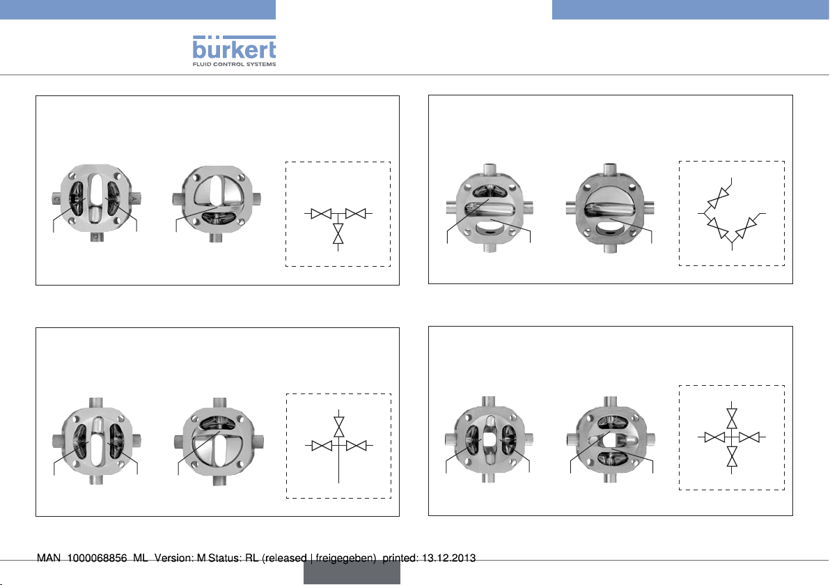
Typ 2035 / 3236
Produktbeschreibung
3-Anschlüsse, 3-Sitze
3C3S
obere Seite untere Seite
A
C
Sitz
U1
Bild 9: Ventilsymbole und Fließbilder - 3C3S
A C
Sitz
U1
D
obere Seite untere Seite
D
B
A
Sitz
Sitz
U2
L1
4-Anschlüsse, 3-Sitze
4C3S
C A
Sitz
Sitz
L1
U2
D
D
B
C
4-Anschlüsse, 3-Sitze
4C3S BD Filterventil
obere Seite untere Seite
A
C
A
A
D
D
C
B
B
Sitz
U1
Bild 11: Ventilsymbole und Fließbilder - 4C3S BD
A
Sitz
U1
C
obere Seite untere Seite
D
B
D
D
Sitz
U2
4-Anschlüsse, 4-Sitze
C
C
Sitz
Sitz
U2
L1
A
C
4C4S
D
B
Sitz
L2
Sitz
L2
A
B
B
A
A
D
C
D
C
B
Bild 10: Ventilsymbole und Fließbilder - 4C3S
54
Bild 12: Ventilsymbole und Fließbilder - 4C4S
deutsch
Page 55

Typ 2035 / 3236
Produktbeschreibung
4-Anschlüsse, 4-Sitze
4C4S DFP Durchfluss-Doppelventil
obere Seite untere Seite
D
A
Sitz
U1
Bild 13: Ventilsymbole und Fließbilder - 4C4S DFP
Sitz
U1
Bild 14: Ventilsymbole und Fließbilder - 4C5S
B
obere Seite untere Seite
A
B1
C
C
Sitz
Sitz
L1
U2
4-Anschlüsse, 5-Sitze
4C5S Chromatography-Ventil
C
C
Sitz
Sitz
L1
U2
B1
D
B
B2
Sitz
L2
A
Sitz
L2
A
A
A
D
B
B1
B2
5.5. Ventilkennzeichnung
Kennzeichnung Ex-Bereich
und Warnhinweise
Typschild
C
Beschriftung Ventilgehäuse
Nennweite und Stutzenmaße
Werkstoff, Charge, Fertigungs-
C
Bild 15: Ventilkennzeichnung
Kennzeichnung
Antriebsausrichtung
Kennzeichnung
Leitungsanschlüsse
auftrag und Serien-Nr.
deutsch
55
Page 56

Typ 2035 / 3236
Produktbeschreibung
5.5.1. Typschild
Baugröße
Typ
2035 RV50 4C 4S-DFP
EPDM-cus D11 -D11
Weld end 19,05x1,65
Pilot 4,2-10 bar
Pmed 10bar
Made in Germany
12345678
Identnummer
Bild 16: Typschild Typ 2035
Robolux
3236 RV50 4C 4S-DFP
EPDM-cus D44 -D44
Weld end 19,05x1,65
Pmed 10bar
Made in Germany
12345678
Bild 17: Typschild Typ 3236
W14UN
W14UN
Bauform
Membranwerkstoff -
Antrieb 1 - Antrieb 2
Anschlussart -
Anschlussmaße
Steuerdruck
Max. Mediumsdruck
Baudatum
Typ - Baugröße - Bauform
Membranwerkstoff -
Antrieb 1 - Antrieb 2
Anschlussart -
Anschlussmaße
Max. Mediumsdruck
Baudatum
Identnummer
5.5.2. Kennzeichnung Ex-Bereich und
Warnhinweise
Siehe Kapitel „3.1.3. Kennzeichnung Ex-Bereich und Warnhinweise“.
5.5.3. Kennzeichnung Leitungsanschlüsse
Alle Leitungsanschlüsse sind mit Buchstaben versehen, in Übereinstimmung mit den Fließbildern (siehe Kapitel „5.4. Ventilsymbole und
Fließbilder“).
5.5.4. Kennzeichnung Antriebsausrichtung
Der Antrieb ist im Bereich von Anschluss A mit einem Kennzeichen
versehen, um die lagerichtige Montage zu erleichtern.
Bild 18: Kennzeichnung Antriebsausrichtung
56
deutsch
Page 57

Typ 2035 / 3236
Aufbau und Funktion
5.6. Vorgesehener Einsatzbereich
Das Membranventil ist für den Einsatz bei verschmutzten und
aggressiven Medien konzipiert, die den Gehäuse- und Dichtwerkstoff nicht angreifen.
Den maximalen Druckbereich laut Typschild beachten.
• Hochreine, sterile, aggressive oder abrasive Medien.
• Höherviskose Medien.
Hinweise für den Einsatz im Ex-Bereich beachten.
Siehe Kapitel „3.1“.
5.6.1. Anwendungsgebiete
z. B. Anlagenbau
Genuss- und Nahrungsmittelindustrie
Abfüllanlagen
Chemische Verfahrenstechnik
Pharmazie
6. AUFBAU UND FUNKTION
6.1. Aufbau Typ 2035
Das Membranventil besteht aus pneumatisch betätigtem Kolbenantrieb, Membran und Multiport-Ventilgehäuse.
Antriebsdeckel
Schalldämpfer
Steuerluftanschluss
Antriebsgehäuse
Abdeckung Position
Näherungsschalter
Abdeckung
Schraube Druckstück
Membran
Ventilgehäuse
Gehäuseschrauben /
-muttern
Bild 19: Kolbengesteuertes Membranventil, Aufbau und
Beschreibung
deutsch
57
Page 58

1(P)
2(A)
1(P)
2(B)
Typ 2035 / 3236
Aufbau und Funktion
6.1.1. Antrieb
Der Antrieb besitzt zwei Antriebskammern, die unabhängig voneinander angesteuert werden können und je auf einen Gehäusesitz
wirken (Doppelantrieb). Im Falle Einfachantrieb ist nur eine Antriebskammer mit Funktionsinnenteilen bestückt.
Federkraft (bei SFA) oder pneumatischer Steuerdruck (bei SFB)
erzeugen die Schließkraft des Antriebs.
Über je eine Spindel, die mit dem Antriebskolben verbunden ist,
wird die Kraft auf das zugehörige Druckstück und die Membran
übertragen.
6.1.2. Steuerfunktionen (SF)
Steuerfunktion A (SFA)
In Ruhestellung durch Federkraft
geschlossen
Steuerfunktion B (SFB)
In Ruhestellung durch Federkraft
geöffnet
6.2. Aufbau Typ 3236
Das Membranventil besteht aus manuell betätigtem Antrieb,
Membran und Multiport-Ventilgehäuse.
Handrad
Antriebsgehäuse
Membran
Ventilgehäuse
Gehäuseschrauben
Bild 20: Manuell betätigtes Membranventil, Aufbau und
Beschreibung
6.2.1. Antrieb
Der Antrieb besitzt zwei Handräder, die unabhängig voneinander
betätigt werden können und je auf einen Gehäusesitz wirken (Doppelantrieb). Im Falle Einfachantrieb ist nur eine Antriebseite bestückt.
Über je eine Spindel, die mit dem Handrad verbunden ist, wird die
Kraft auf das zugehörige Druckstück und die Membran übertragen.
58
deutsch
Page 59

Typ 2035 / 3236
Technische Daten
7. TECHNISCHE DATEN
7.1. Konformität
Die Membranventile Typ 2035 und Typ 3236 sind konform zu den EGRichtlinien entsprechend der EG-Konformitätserklärung.
7.2. Normen
Die angewandten Normen, mit denen die Konformität mit den EG-Richtlinien nachgewiesen wird, sind in der EG-Baumusterprüfbescheinigung
und/oder der EG-Konfomitätserklärung nachzulesen.
7.3. Zulassungen
Das Produkt ist entsprechend der ATEX Richtlinie 94/9/EG der
Kategorie 2 G/D zum Einsatz in Zone 1 und 21 zugelassen.
Hinweise für den Einsatz im Ex-Bereich beachten.
Siehe Kapitel „3.1“.
Ventilgehäuse Edelstahl: EN ISO 10204 3.1
Polypropylen: USP VI (Werkstoff PR)
Membran FDA CFR 177.2600 für EPDM, FKM und Silikon
FDA CFR 177.1550 für PFA
USP VI für EPDM, PFA/EPDM, Silikon und
PFR 91
7.5. Betriebsbedingungen
Die zulässigen Bereiche auf dem Typschild des Geräts
beachten.
Umgebungstemperatur -10 ... +60 °C
höhere Temperaturen auf Anfrage
Betriebstemperatur max. +85 °C
Relative Luftfeuchte max. 80 % (nicht kondensierend)
7.6. Mechanische Daten
Abmessungen siehe Datenblatt
Werkstoffe
Gehäusematerial Edelstahl: 1.4435/316L
(andere Werkstoffe auf Anfrage)
PP (hochreines Polypropylen)
PP (Polypropylen USP VI)
PVDF (Steril Polivinyl-Difluoride)
Membran EPDM, Silikon, PFA/EPDM, FKM, PFR 91
Antrieb epoxidpulverbeschichtetes Aluminium
PP-Gehäuse (nur Typ 2035 RV50)
7.4. Typschild
Siehe Kapitel „5.5. Ventilkennzeichnung“.
deutsch
59
Page 60

Typ 2035 / 3236
Technische Daten
Anschlüsse
Leitungsanschlüsse Schweißstutzen DIN EN ISO 1127
(ISO 4200), DIN 11850 Reihe 2,
ASME BPE
SMS 3008, BS4825 (weitere Schweißanschlüsse, Clamp und Sterilverschraubungen auf Anfrage)
Steuerluftanschluss G1/8
Oberflächengüte innen Ra 0,5 µm passiviert
außen Ra 3,2 µm glasperlengestrahlt
optional elektropoliert
(weitere Oberflächengüten auf Anfrage)
Einbaulage beliebig, vorzugsweise Anschluss B nach
unten; für Selbstentleerung siehe Kapitel
„5.3. Selbstentleerung der Ventile“
Lebensdauer
Die Gerätelebensdauer wird stark von den Einsatzbedingungen
beeinflusst. Insbesondere die Membranlebensdauer hängt sehr stark
von den Betriebsbedingungen, wie z. B. Medium, Temperaturen,
Schaltfrequenz, Druck, usw. ab.
7.6.1. Membran
Die Membran dichtet das Ventil ab. Sie muss sorgfältig gewählt werden.
Die Auswahl des Werkstoffs sollte abgestimmt sein auf das Prozessmedium, die Temperatur und die mechanischen Gegebenheiten (z. B.
Betriebsdruck, Schalthäufigkeit, etc.). Die nachfolgende Tabelle zeigt
die Standardwerkstoffe.
Konformität zu FDA CFR 21 §177.2600 bzw. §177.1550 und USP
VI Zertifizierung siehe „Tab. 1: Membranwerkstoffe“.
Membranwerkstoff
EPDM peroxidvulkanisierter
PFA /
EPDM
FKM Fluorkautschuk Säuren und
Silikon Platin-stabilisierter
PFR 91 PFR 91
Tab. 1: Membranwerkstoffe
Werkstoffbeschreibung
Äthylen-PropylenKautschuk
PFA
kaschiertes EPDM
Silikonkautschuk
Fluorkautschuk
Anwendung FDA USP VI
oxidierende
Chemikalien,
Dampf und
Heißwasser
die meisten
Chemikalien
und Säuren
mineralische
Öle
aliphatische
Öle
aliphatische
Öle
x x
x x
x
x x
x
60
deutsch
Page 61

Typ 2035 / 3236
Technische Daten
7.7. Fluidische Daten
Medien
Durchflussmedien hochrein, steril, aggressiv,
(siehe auch Kapitel „7.6.1. Membran“)
Mediendruck RV50 max. 8 bar
RV70/RV110 max. 6 bar
(abhängig von Antrieb, Membran und Gehäusewerkstoff)
siehe Kapitel „7.7.1. Druckbereiche“
Medientemperatur Edelstahl -10 bis max. +120 °C
(max. +140 °C, 30 Min.)
Kunststoff -10 bis max. +40 °C (siehe
„Bild 22“)
PFA-Membran 0 bis max. +95 °C
Viskosität bis zähflüssig
Hinweise für den Einsatz im Ex-Bereich beachten.
Siehe Kapitel „3.1“.
Steuermedium Neutrale Gase, Luft getrocknet (min. 10 K
unter min. Betriebstemperatur), vorzugsweise
ungeölt
Steuerdruck
4)
6 ... 10 bar (nur Typ 2035)
ab 4,2 bar (bei reduziertem Mediumsdruck)
auf Anfrage
2)
7.7.1. Druckbereiche
Steuerdruck und Mediumsdruck
EPDM, FKM, Silikon,
Antriebsbezeichnung
Steuerdruck [bar]
PFR 91
statische
Dichtheit
[bar]
dynamische
Dichtheit
[bar]
RV50 6 ... 10 8 6 8 6
RV50
EC04
4,2 ... 10 6 4 6 4
RV70 6 ... 10 6 4 6 4
RV70
EC04
4,2 ... 10 3 2 3 2
RV110 6 ... 10 6 4 6 4
RV110
EC04
4,2 ... 10 3 2 3 2
Tab. 2: Statische und dynamische Dichtheit
PFA / EPDM
statische
Dichtheit
[bar]
dynamische
Dichtheit
[bar]
2) Druckangabe [bar]: Überdruck zum Atmosphärendruck
deutsch
61
Page 62
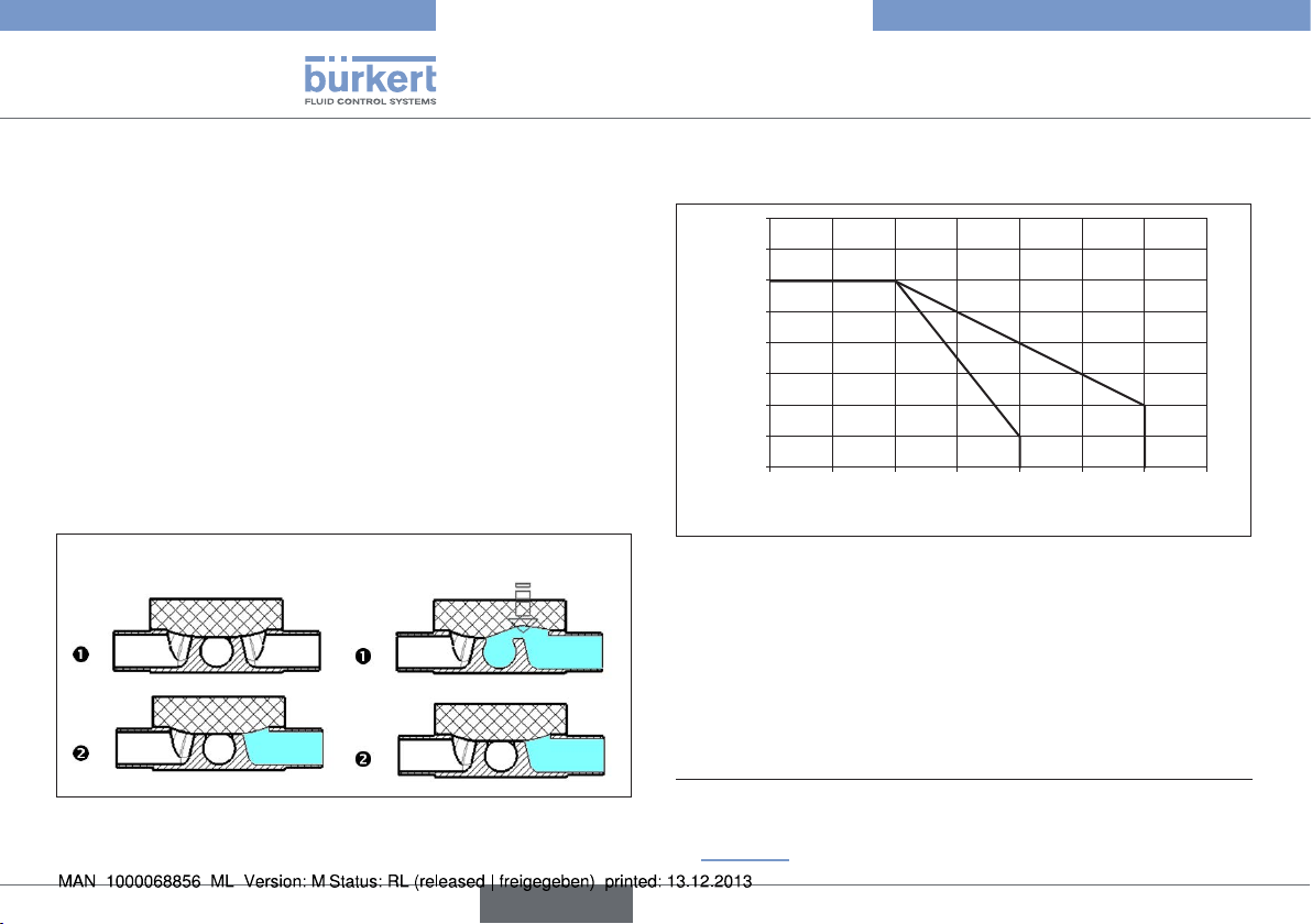
Typ 2035 / 3236
Technische Daten
Anmerkungen
Statische Dichtheit:
Ventil ist geschlossen (Membran liegt am Gehäusesitz an). Druck
steht auf einer Seite des Gehäusesitzes an. Bei dem angegebenem
Druck entsteht keine Leckage über den Gehäusesitz.
Dynamische Dichtheit:
Ventil ist geöffnet und wird vom Medium durchströmt. Die Abström-
seite wird durch nachfolgende Komponenten nur geringfügig abgedrosselt. Druck steht auf beiden Seiten des Gehäusesitzes an. Das
Ventil wird geschlossen (SFA durch Federkraft; SFB durch Steuerdruck). Bei dem angegebenem Druck schließt das Ventil über den
Gehäusesitz dicht ab.
Statische Dichtheit:
Dynamische Dichtheit:
Zulässiger Mediumsdruck in Abhängigkeit von der Mediumstemperatur bei Kunststoffgehäusen
8,0
7,0
3)
6,0
5,0
4,0
3,0
2,0
Mediumsdruck [bar]
1,0
0,0
0 20 40 60 80 100 120 140
PP
Temperatur [°C]
PVDF
Bild 22: Zulässiger Mediumsdruck in Abhängigkeit von der
Mediumstemperatur bei Kunststoffgehäusen
Bild 21: Statische und Dynamische Dichtheit
62
3) Der angegebene max. Mediumsdruck bezieht sich auf die
statische Dichtheit. Weitere Informationen hierzu siehe
„Montage“.
deutsch
Page 63

Typ 2035 / 3236
Technische Daten
7.7.2. Kv-Wert
Nennweite
DN
Gehäuseanschluss
[mm]
10 3/8“ RV50 0,8 0,7
15 1/2“ RV50 2,5 2
20 3/4“ RV50 3,5 3,3
25 1“ RV70 10 9
40 1 1/2“ RV110 27 22
50 2“ RV110 35 27
Tab. 3: Kv-Wert
Ventilgröße Antrieb Kv-Wert Wasser [m³/h]
für Membranwerkstoff
Bezeichnung
Alle Kv-Werte gemessen an Ventilen mit Anschlüssen nach
ASME BPE.
EPDM,
FKM
PFA
MONTAGE
7.8. Sicherheitshinweise
GEFAHR!
Verletzungsgefahr durch hohen Druck in Anlage/Gerät.
▶ Vor Arbeiten an Anlage oder Gerät, den Druck abschalten und
Leitungen entlüften/entleeren.
WARNUNG!
Verletzungsgefahr bei unsachgemäßer Montage.
▶ Die Montage darf nur autorisiertes Fachpersonal mit geeignetem
Werkzeug durchführen.
Verletzungsgefahr durch ungewolltes Einschalten der Anlage
und unkontrollierten Wiederanlauf.
▶ Anlage vor unbeabsichtigtem Betätigen sichern.
▶ Nach der Montage einen kontrollierten Wiederanlauf gewährleisten.
7.9. Vor dem Einbau
• Vor dem Anschluss des Ventils auf fluchtende Rohrleitungen
achten.
• Die Durchflussrichtung beachten.
deutsch
63
Page 64

7.9.1. Einbaulage
• Die Einbaulage des kolbengesteuerten Membranventils ist
beliebig, vorzugsweise Anschluss B / Schalldämpfer nach unten.
• Einbau für Selbstentleerung des Gehäuses:
siehe Kapitel „5.3. Selbstentleerung der Ventile“
Typ 2035 / 3236
Technische Daten
Schalldämpfer
7.9.2. Vorbereitende Arbeiten
→ Rohrleitungen von Verunreinigungen säubern (Dichtungsmaterial,
Metallspäne etc.).
→ Rohrleitungen abstützen und ausrichten.
Geräte mit Schweißgehäuse
HINWEIS!
Beschädigung der Membran bzw. des Antriebs.
▶ Vor dem Einschweißen des Gehäuses, Antrieb und Membran
demontieren.
Antrieb vom Ventilgehäuse demontieren:
→ Antrieb in die obere Antriebsposition bringen (SFA durch Anlegen
von Steuerdruck, SFB durch Entfernen des Steuerdrucks).
→ Position des Antriebs zum Ventilgehäuse markieren.
→ Die vier Gehäuseschrauben / Muttern lösen, die das Ventilgehäuse
und den Antrieb verbinden. Antrieb und Membran entfernen.
64
deutsch
Antrieb
Membran
Ventilgehäuse
Gehäuseschrauben
und Scheiben
Bild 23: Montage
7.10. Einbau
7.10.1. Gehäuse montieren
Schweißgehäuse
→ Ventilgehäuse in Rohrleitungssystem einschweißen.
Andere Gehäuseausführungen
→ Gehäuse mit Rohrleitung verbinden.
Page 65

Typ 2035 / 3236
Technische Daten
7.10.2. Antrieb montieren (Schweißgehäuse)
→ Antrieb in die obere Antriebsposition bringen (SFA durch Anlegen
von Steuerdruck, SFB durch Entfernen des Steuerdrucks).
→ Einheit Antrieb / Membran lagerichtig auf das Gehäuse aufsetzen
(so dass die zuvor angebrachten Markierungen fluchten).
→ Gehäuseschrauben / Muttern kreuzweise festziehen, bis ein
sichtbarer, gleichmäßiger mechanischer Kontakt zwischen Ventilkörper, Membran und Antrieb gegeben ist.
→ Gehäuseschrauben / Muttern zweimal mit einer Vierteldrehung
kreuzweise, mit jeweils gleichem Drehmoment, festziehen.
7.10.3. Dichtheit / Ventilfunktion
sicherstellen
WARNUNG!
Verletzungsgefahr durch austretendes Durchflussmedium.
▶ Die Gehäuseschrauben ausreichend festziehen.
Unnötig große Kraft an den Gehäuseschrauben / Muttern
führt zu stärkerem Verschleiß und damit zu einer Verkürzung
der Lebensdauer der Membran.
Wird bei erhöhtem Mediumsdruck das Ventil undicht:
→ Gehäuseschrauben / Muttern kreuzweise eine Achteldrehung
anziehen, bis das Ventil wieder dicht ist.
Durch diese Vorgehensweise werden Membran und Druckstück
optimal zueinander angeordnet und die Ventilfunktion sichergestellt.
7.11. Pneumatischer Anschluss
(nur Typ 2035)
GEFAHR!
Verletzungsgefahr durch hohen Druck in Anlage/Gerät.
▶ Vor Arbeiten an Anlage oder Gerät, den Druck abschalten und
Leitungen entlüften/entleeren.
WARNUNG!
Verletzungsgefahr durch ungeeignete Anschlussschläuche.
Schläuche die dem Druck- und Temperaturbereich nicht standhalten, können zu gefährlichen Situationen führen.
▶ Nur Schläuche verwenden, die für den angegeben Druck- und
Temperaturbereich zugelassen sind.
▶ Die Datenblattangaben der Schlauchhersteller beachten.
7.11.1. Anschluss des Steuermediums
Belegung der Steuerluftanschlüsse siehe Installations- und Maßzeichnung, die mit dem Ventil mitgeliefert wird. Vergleiche auch
Angaben im Kapitel „6. Aufbau und Funktion“.
Es werden Pneumatikschläuche min. der Größe 6/4 mm empfohlen.
Bei größeren Leitungslängen sind die Schlauchquerschnitte darauf
abzustimmen.
deutsch
65
Page 66

Typ 2035 / 3236
Technische Daten
In aggressiver Umgebung sowie in Situationen, bei denen
Feuchtigkeit durch den Abluftanschluss bzw. Schalldämpfer
in den Antrieb eindringen könnte ist die Abluft zu fassen und
in unkritische Umgebung abzuleiten.
Vorgehensweise:
→ Gelbe Schutzstopfen entfernen.
→ Steuermedium an Steuerluftanschluss mit Hilfe der mitgelieferten
Installations- und Maßzeichnung anschließen.
Steuerfunktion B:
Zur Schonung der Membran, den Steuerdruck so gering
wie möglich wählen.
Steuerluftanschlüsse
Bild 24: Pneumatischer Anschluss, Einbau Näherungsschalter
Anschlüsse für
Näherungssensoren
7.12. Einbau des induktiven
Näherungsschalters
Der Einbau erfolgt über die M8 x 1- oder M12 x 1-Gewinde an der
Seite des Antriebs (bei RV50 mit PP-Haube auf der Oberseite).
→ Anschluss mit Hilfe der mitgelieferten Installations- und Maß-
zeichnung festlegen.
→ Gelbe Schutzstopfen entfernen.
→ Antrieb auf Position bringen, die mit Näherungsschalter abge-
fragt werden soll:
RV50/70:
Unterer Näherungsschalter: Antrieb in die untere Antriebsposition bringen (SFA durch Entfernen des Steuerdrucks, SFB
durch Anlegen von Steuerdruck).
Oberen Näherungsschalter: Antrieb in die obere Antriebsposition bringen (SFA durch Anlegen von Steuerdruck, SFB durch
Entfernen des Steuerdrucks).
RV110:
Antrieb in die untere Antriebsposition bringen (SFA durch Entfernen des Steuerdrucks, SFB durch Anlegen von Steuerdruck).
→ Näherungsschalter hineinschrauben, bis sie an den Druckstücken
anstehen.
→ Näherungsschalter danach eine halbe bis eine Drehung
herausdrehen.
→ Näherungsschalter mit einer Sicherungsmutter sichern (die
zweite beiliegende Mutter und die beiden Scheiben werden
nicht benötigt).
→ Funktion der Näherungsschalter prüfen.
66
deutsch
Page 67

Typ 2035 / 3236
Bedienung und Funktion
HINWEIS!
Eindringen von Feuchtigkeit und Schmutz!
▶ Wird kein Näherungsschalter verwendet, Gewindeanschluss
M8 x 1 bzw. M12 x 1 mit einem Schutzstopfen verschließen.
8. BEDIENUNG UND FUNKTION
8.1. Sicherheitshinweise
WARNUNG!
Gefahr durch unsachgemäßen Bedienung.
Nicht sachgemäße Bedienung kann zu Verletzungen, sowie
Schäden am Gerät und seiner Umgebung führen.
▶ Das Bedienungspersonal muss den Inhalt der Bedienungsanlei-
tung kennen und verstanden haben.
▶ Die Sicherheitshinweise und die bestimmungsgemäße Verwen-
dung müssen beachtet werden.
▶ Nur ausreichend geschultes Personal darf die Anlage/das Gerät
bedienen.
8.2. Typ 2035 - Pneumatische
Betätigung
Druckluft steuert das Membranventil. Über die Steuerluftanschlüsse
erreicht die Druckluft die Kolben und betätigt diese. Dadurch öffnen
oder schließen die Ventile.
Belegung der Steuerluftanschlüsse siehe Installations- und
Maßzeichnung, die mit dem Ventil mitgeliefert wird.
deutsch
67
Page 68

Typ 2035 / 3236
Elektrische Vorsteuerung
8.3. Typ 3236 - Manuelle Betätigung
Das Membranventil wird durch Handräder betätigt.
Ventilsitz schließen Drehen im Uhrzeigersinn
Ventilsitz öffnen Drehen gegen den Uhrzeigersinn
Ventilsitz schließen
Ventilsitz öffnen
Bild 25: Typ 3236
9. ELEKTRISCHE
VORSTEUERUNG
Der elektrische Anschluss des Vorsteuerventils ist in der
Bedienungsanleitung des Vorsteuerventils beschrieben.
Hinweise für den Einsatz im Ex-Bereich beachten.
Siehe Kapitel „3.1“.
10. DEMONTAGE
GEFAHR!
Verletzungsgefahr durch Mediumsaustritt und
Druckentladung.
Der Ausbau eines Geräts das unter Druck steht ist wegen plötzlicher Druckentladung oder Mediumsaustritt gefährlich.
▶ Vor dem Ausbau den Druck abschalten und Leitungen entlüften.
Wird das Ventil nach der Demontage weiter verwendet, muss
bei Schweißgehäusen der Antrieb vor der Demontage entfernt
werden. Hierfür die Hinweise zur Montage beachten.
Vorgehensweise:
→ Pneumatischer Anschluss lösen.
→ Gerät demontieren.
68
deutsch
Page 69

Typ 2035 / 3236
Wartung, Reinigung
11. WARTUNG, REINIGUNG
11.1. Sicherheitshinweise
GEFAHR!
Verletzungsgefahr durch hohen Druck in Anlage/Gerät.
▶ Vor Arbeiten an Anlage oder Gerät, den Druck abschalten und
Leitungen entlüften/entleeren.
Gefahr durch Stromschlag.
▶ Vor Arbeiten an Anlage oder Gerät, die Spannung abschalten und
vor Wiedereinschalten sichern.
▶ Die geltenden Unfallverhütungs- und Sicherheitsbestimmungen
für elektrische Geräte beachten.
WARNUNG!
Verletzungsgefahr bei unsachgemäßen Wartungsarbeiten.
▶ Die Montage darf nur autorisiertes Fachpersonal mit geeignetem
Werkzeug durchführen.
Verletzungsgefahr durch ungewolltes Einschalten der Anlage
und unkontrollierten Wiederanlauf.
▶ Anlage vor unbeabsichtigtem Betätigen sichern.
▶ Nach der Wartung einen kontrollierten Wiederanlauf gewährleisten.
11.2. Wartungsintervalle
Prüfen Sie regelmäßig die Membranventile auf ihren ordnungsgemäßen
Zustand hinsichtlich der Montage, der Installation und des Betriebs.
Berücksichtigen Sie die folgenden Faktoren bei der Festlegung der
Prüfungsintervalle:
• Betriebsbedingungen (Auslastungsgrad, Fehlbedienung),
• Herstellerangaben in der technischen Dokumentation (z. B.
mechanische Lebensdauer),
• größere Veränderungen im System.
11.3. Wartungsarbeiten
Im Rahmen der Wartung prüfen:
• Leitungen auf festen Sitz
• Kunstoffgehäuse auf äußerliche Veränderungen
• Einhaltung der zulässigen Temperaturen (siehe Technische Daten)
• bestimmungsgemäße Funktion
11.3.1. Antrieb
Der Antrieb des Membranventils ist, wenn für den Einsatz die Hinweise dieser Bedienungsanleitung beachtet werden, wartungsfrei.
deutsch
69
Page 70

Typ 2035 / 3236
Wartung, Reinigung
11.3.2. Verschleißteile des Membranventils
Die Membran unterliegt einer natürlichen Abnutzung
→ Bei Undichtheiten die Membran austauschen.
(siehe Kapitel „12. Instandhaltung“).
Eine ausgebeulte Membran, kann zur Reduzierung des
Durchflusses führen.
Der Austausch der Verschleißteile ist in Kapitel
„12. Instandhaltung“ beschrieben.
11.4. Reinigung
HINWEIS!
Vermeidung von Schäden durch Reinigungsmittel.
▶ Die Verträglichkeit der Mittel mit den Werkstoffen des Geräts vor
der Reinigung prüfen.
Epoxidpulverbeschichtung wird durch falsche Reinigungsmittel angegriffen.
▶ Oberfläche mit einem für dieses Material geeigneten Mittel reini-
gen, z. B. mit 25-prozentigem Alkohol oder Aceton.
Hinweise für den Einsatz im Ex-Bereich beachten.
Siehe Kapitel „3.1“.
Antrieb
Die Oberfläche des Antriebs mit einem feuchten Tuch reinigen. Nur
Reinigungsmittel verwenden, welche die Oberfläche des Antriebs
nicht angreifen.
Folgende Antriebsausführungen werden angeboten:
Antriebswerkstoff (Merkmal AM):
AM = AE: Antriebsgehäuse aus epoxibeschichtetem
Aluminium
AM = AP: Antriebsdeckel aus Polypropylen (PP)
AM = AE und
VAR = NC31: Antriebsgehäuse aus Aluminium
Gehäuse / Membran
Die Gehäuse sind CIP-fähig. Die Ventile mit Reinigungsmitteln rei-
nigen, welche den Gehäuse- und Membranwerkstoff nicht angreifen.
Reinigungsmittel mit hohem pH-Wert vermeiden.
70
deutsch
Page 71

Typ 2035 / 3236
Instandhaltung
12. INSTANDHALTUNG
12.1. Sicherheitshinweise
GEFAHR!
Verletzungsgefahr durch hohen Druck in Anlage/Gerät.
▶ Vor Arbeiten an Anlage oder Gerät, den Druck abschalten und
Leitungen entlüften/entleeren.
Gefahr durch Stromschlag.
▶ Vor Arbeiten an Anlage oder Gerät, die Spannung abschalten und
vor Wiedereinschalten sichern.
▶ Die geltenden Unfallverhütungs- und Sicherheitsbestimmungen
für elektrische Geräte beachten.
WARNUNG!
Verletzungsgefahr bei unsachgemäßer Instandhaltung.
▶ Die Montage darf nur autorisiertes Fachpersonal mit geeignetem
Werkzeug durchführen.
▶ Die Anzugsmomente müssen eingehalten werden.
▶ Nach Abschluss der Arbeiten Ventil auf Dichtheit und Funktion
prüfen.
Verletzungsgefahr durch ungewolltes Einschalten der Anlage
und unkontrollierten Wiederanlauf.
▶ Anlage vor unbeabsichtigtem Betätigen sichern.
▶ Nach der Wartung einen kontrollierten Wiederanlauf gewährleisten.
12.2. Austausch der Membran
Bei Verschleißerscheinungen oder zur Anpassung der Ventile an veränderte Einsatzbedingungen kann ein Membranwechsel erforderlich sein.
Die jeweilige Vorgehensweise wird im Folgenden abhängig vom
Antriebstyp und dem Material des Ventilkörpers beschrieben.
Benötigtes Ersatzteil
• Membran
12.2.1. RV50, RV70 und RV110
handbetätigt / Doppelantrieb
WARNUNG!
Verletzungsgefahr durch Durchflussmedium, Betriebsdruck
und beweglichen Teilen.
▶ Vor der Demontage prüfen, ob das Ventil drucklos und vollständig
entleert ist.
▶ Schutzkleidung tragen.
deutsch
71
Page 72

Typ 2035 / 3236
Instandhaltung
Demontage Antrieb und Membran
→ Position des Antriebs zum Ventilgehäuse markieren.
→ Die vier Gehäuseschrauben / -muttern lösen, die das Ventilgehäuse
und den Antrieb verbinden. Das Ventilgehäuse entfernen
→ Handräder in Stellung Geschlossen drehen
weiterdrehen).
2
(keinesfalls
→ Druckstücke nach unten aus dem Antrieb herausnehmen
→ Membran seitlich aus den Druckstücken entfernen
Handrad
1
3
Gehäuseschrauben
Bild 26: Demontage handbetätigter Doppelantrieb
Druckstücke Membran
4
.
2
4
Montage Antrieb und Membran
→ Membran in die T-Führung der Druckstücke einsetzen
1
→ Druckstücke in den Antrieb einführen
.
→ Handräder in Stellung Offen drehen
6
.
7
.
5
.
→ Einheit Antrieb / Membran lagerichtig auf das Gehäuse aufsetzen
3
.
(so dass die zuvor angebrachten Markierungen fluchten).
→ Gehäuseschrauben / -muttern kreuzweise festziehen, bis ein
sichtbarer, gleichmäßiger mechanischer Kontakt zwischen Ventilkörper, Membran und Antrieb gegeben ist
8
.
→ Gehäuseschrauben / -muttern zweimal mit einer Vierteldrehung
kreuzweise, mit jeweils gleichem Drehmoment, festziehen.
Handrad
7
5
Membran
6
Druckstücke
Gehäuseschrauben
8
72
Bild 27: Montage handbetätigter Doppelantrieb
deutsch
Page 73

Typ 2035 / 3236
Instandhaltung
Dichtheit / Ventilfunktion sicherstellen
WARNUNG!
Verletzungsgefahr durch austretendes Durchflussmedium.
▶ Gehäuseschrauben / -muttern ausreichend festziehen.
Unnötig große Kraft an den Gehäuseschrauben / -muttern
hingegen führt zu stärkerem Verschleiß und damit zu einer
Verkürzung der Lebensdauer der Membran.
Wird bei erhöhtem Mediumsdruck das Ventil undicht:
→ Gehäuseschrauben / -muttern kreuzweise eine Achteldrehung
anziehen, bis das Ventil wieder dicht ist.
Durch diese Vorgehensweise werden Membran und Druckstücke
optimal zueinander angeordnet und die Ventilfunktion sichergestellt.
12.2.2. RV50, RV70 und RV110 handbetätigt
/ Einzelantrieb
WARNUNG!
Verletzungsgefahr durch Durchflussmedium, Betriebsdruck
und beweglichen Teilen.
▶ Vor der Demontage prüfen, ob das Ventil drucklos und vollständig
entleert ist.
▶ Schutzkleidung tragen.
Demontage Antrieb und Membran
→ Position des Antriebs zum Ventilgehäuse markieren.
→ Schraube (bei RV50 Inbus, bei RV70/RV110 Sechskant) an der
1
Seite des Antriebs lösen
.
→ Die vier Gehäuseschrauben / -muttern lösen, die das Ventilgehäuse
2
und den Antrieb verbinden
→ Handrad in Stellung Geschlossen drehen
. Das Ventilgehäuse entfernen.
3
.
→ An der Membran die Druckstücke aus dem Antrieb herausziehen
→ Membran seitlich aus den Druckstücken entfernen
Handrad
3
1
2
4
Schraube
Bild 28: Demontage handbetätigter Einzelantrieb
Gehäuseschrauben
Druckstücke Membran
5
.
5
4
.
deutsch
73
Page 74

Typ 2035 / 3236
Instandhaltung
Montage Antrieb und Membran
6
Membran
9
10
Schraube
Bild 29: Montage handbetätigter Einzelantrieb
7
Druckstücke
11
Gehäuseschrauben
→ Membran in die T-Führung der Druckstücke einsetzen
Handrad
6
.
→ Druckstück in den Antrieb einführen
Dabei beachten: Die Gewinde von Druckstückspindel und Handradspindel müssen ineinandergreifen
→ Handrad in Stellung Offen drehen
7
.
8
.
9
.
→ Schraube (bei RV50 Inbus, bei RV70/RV110 Sechskant) an der
10
8
Seite des Antriebs positionieren und anziehen
.
→ Die Einheit Antrieb / Membran lagerichtig auf das Gehäuse auf-
setzen (so dass die zuvor angebrachten Markierungen fluchten).
→ Gehäuseschrauben / -muttern kreuzweise festziehen, bis ein
sichtbarer, gleichmäßiger mechanischer Kontakt zwischen Ventilkörper, Membran und Antrieb gegeben ist
11
.
→ Gehäuseschrauben / -muttern zweimal mit einer Vierteldrehung
kreuzweise, mit jeweils gleichem Drehmoment, festziehen.
Dichtheit / Ventilfunktion sicherstellen
WARNUNG!
Verletzungsgefahr durch austretendes Durchflussmedium.
▶ Gehäuseschrauben / -muttern ausreichend festziehen.
Unnötig große Kraft an den Gehäuseschrauben / -muttern
hingegen führt zu stärkerem Verschleiß und damit zu einer
Verkürzung der Lebensdauer der Membran.
Wird bei erhöhtem Mediumsdruck das Ventil undicht:
→ Gehäuseschrauben / -muttern kreuzweise eine Achteldrehung
anziehen, bis das Ventil wieder dicht ist.
Durch diese Vorgehensweise werden Membran und Druckstück
optimal zueinander angeordnet und die Ventilfunktion sichergestellt.
74
deutsch
Page 75

Typ 2035 / 3236
Instandhaltung
12.2.3. RV50 und RV70 pneumatischer
Antrieb
WARNUNG!
Verletzungsgefahr durch Durchflussmedium, Betriebsdruck
und beweglichen Teilen.
▶ Vor der Demontage prüfen, ob das Ventil drucklos und vollständig
entleert ist.
▶ Schutzkleidung tragen.
Verletzungsgefahr beim Öffnen des Antriebs.
Der Antrieb enthält gespannte Federn. Beim Öffnen des Antriebs
kann es durch herausspringende Federn zu Verletzungen kommen.
▶ Der Antrieb darf nicht geöffnet werden.
Demontage Antrieb und Membran
→ Antrieb in die obere Antriebsposition bringen (SFA durch Anlegen
von Steuerdruck, SFB durch Entfernen des Steuerdrucks).
→ Position des Antriebs zum Ventilgehäuse markieren.
→ Die vier Gehäuseschrauben / -muttern lösen, die das Ventilgehäuse
und den Antrieb verbinden. Das Ventilgehäuse entfernen
1
→ Abdeckungen abnehmen (bei RV50 mit PP-Haube: Schalldämpfer
2
und Schraube)
→ Gewindestift an den Druckstücken lockern
.
3
.
→ An der Membran die Druckstücke nach unten aus dem Antrieb
4
herausziehen
.
→ Membran seitlich aus den Druckstücken entfernen
2
1
Gehäuseschrauben
Bild 30: Demontage pneumatischer Antrieb RV50, RV70
.
Druckstücke Membran
4
3
Gewindestift
5
.
5
deutsch
75
Page 76

Typ 2035 / 3236
Instandhaltung
Montage Antrieb und Membran
VORSICHT!
Verletzungsgefahr durch bewegliche Teile im Antrieb.
▶ Beim Anlegen oder Entfernen des Steuerdrucks am Antrieb Glied-
maßen und Gegenstände von Öffnungen des Antriebs fernhalten.
→ Membran in die T-Führung der Druckstücke einsetzen
sicherstellen, dass die vier Distanzhülsen montiert sind
für RV70).
Für eine leichtere Montage der Drückstücke sollten sich
die Antriebsspindeln in der unteren Position (Schließen)
befinden (SFA durch Entfernen des Steuerdrucks, SFB
durch Anlegen von Steuerdruck).
→ Druckstücke in den Antrieb einsetzen
dass die Antriebsspindeln ganz in die entsprechenden Aussparungen an den Druckstücken eintauchen
8
. Dabei darauf achten,
9
.
→ Gewindestifte an den Druckstücken festziehen.
6
. Dabei
7
10
.
→ Abdeckungen schließen (bei RV50 mit PP-Haube: Schalldämper
11
und Schraube)
.
→ Antrieb in die obere Antriebsposition bringen (SFA durch Anlegen
von Steuerdruck, SFB durch Entfernen des Steuerdrucks).
→ Einheit Antrieb / Membran lagerichtig auf das Gehäuse aufsetzen
(so dass die zuvor angebrachten Markierungen fluchten).
→ Gehäuseschrauben / -muttern kreuzweise festziehen, bis ein
sichtbarer, gleichmäßiger mechanischer Kontakt zwischen Ventilkörper, Membran und Antrieb gegeben ist
12
.
(nur
→ Gehäuseschrauben / -muttern zweimal mit einer Vierteldrehung
kreuzweise, mit jeweils gleichem Drehmoment, festziehen.
→ Antriebe SFA: Steuerdruck entfernen.
6
11
Membran
7
Distanzhülse
Antriebsspindeln
Bild 31: Montage pneumatischer Antrieb RV50, RV70
8
10
Gewindestift
9
12
GehäuseschraubenDruckstücke
76
deutsch
Page 77

Typ 2035 / 3236
Instandhaltung
Dichtheit / Ventilfunktion sicherstellen
WARNUNG!
Verletzungsgefahr durch austretendes Durchflussmedium.
▶ Gehäuseschrauben / -muttern ausreichend festziehen.
Unnötig große Kraft an den Gehäuseschrauben / -muttern
hingegen führt zu stärkerem Verschleiß und damit zu einer
Verkürzung der Lebensdauer der Membran.
Wird bei erhöhtem Mediumsdruck das Ventil undicht:
→ Gehäuseschrauben / -muttern kreuzweise eine Achteldrehung
anziehen, bis das Ventil wieder dicht ist.
Durch diese Vorgehensweise werden Membran und Druckstücke
optimal zueinander angeordnet und die Ventilfunktion sichergestellt.
→ Ventil mehrmals schalten und bei Bedarf die Gehäuseschrauben
/ -muttern nochmals nachziehen.
12.2.4. RV110 Antrieb
WARNUNG!
Verletzungsgefahr durch Durchflussmedium, Betriebsdruck
und beweglichen Teilen.
▶ Vor der Demontage prüfen, ob das Ventil drucklos und vollständig
entleert ist.
▶ Schutzkleidung tragen.
Verletzungsgefahr beim Öffnen des Antriebs.
Der Antrieb enthält gespannte Federn. Beim Öffnen des Antriebs
kann es durch herausspringende Federn zu Verletzungen kommen.
▶ Der Antrieb darf nicht geöffnet werden.
Demontage Antrieb und Membran
→ Position des Antriebs zum Ventilgehäuse markieren.
→ Antrieb in die obere Antriebsposition bringen (SFA durch Anlegen
von Steuerdruck, SFB durch Entfernen des Steuerdrucks).
→ Die vier Gehäuseschrauben / -muttern lösen, die das Ventilgehäuse
und den Antrieb verbinden. Das Ventilgehäuse entfernen
→ Führungsbolzen lösen und entnehmen
→ Membran und Druckstücke um 45° drehen
4
ziehen
.
2
.
3
und diese heraus-
→ Membran seitlich aus den Druckstücken entnehmen
1
5
.
.
deutsch
77
Page 78

Typ 2035 / 3236
Instandhaltung
Für eine leichtere Montage der Drückstücke sollten sich die
Antriebsspindeln in der unteren Position (Schließen) befinden
(SFA durch Entfernen des Steuerdrucks, SFB durch Anlegen
von Steuerdruck).
1
Führungsbolzen
2
Bild 32: Demontage pneumatischer Antrieb RV110
Montage Antrieb und Membran
VORSICHT!
Verletzungsgefahr durch bewegliche Teile im Antrieb.
▶ Beim Anlegen oder Entfernen des Steuerdrucks am Antrieb Glied-
maßen und Gegenstände von Öffnungen des Antriebs fernhalten.
3
45°
4
→ Membran in die T-Führung der Druckstücke einsetzen
sicherstellen, dass die vier Distanzhülsen montiert sind
78
MembranDruckstücke
6
7
deutsch
5
. Dabei
.
→ Druckstücke in den Antrieb einsetzen
dass die Antriebsspindeln in die entsprechenden Aussparungen
an den Druckstücken vollständig eintauchen
HINWEIS!
Beschädigung der Membran und Fehlfunktion des Ventils!
• Membran und Druckstücke nur maximal soweit verdrehen, bis
die Schraubenbohrungen von Antrieb und Membran fluchten.
8
. Dabei darauf achten,
9
.
→ Membran und Druckstück um maximal 45° verdrehen, bis die
Bohrungen der Membran mit denen im Antrieb übereinstimmen
10
.
→ Führungsbolzen einschrauben und mit ca. 10 Nm anziehen
→ Antrieb in die obere Antriebsposition bringen (SFA durch Anlegen
von Steuerdruck, SFB durch Entfernen des Steuerdrucks).
→ Einheit Antrieb / Membran lagerichtig auf das Gehäuse aufsetzen
12
(so dass die zuvor angebrachten Markierungen fluchten).
→ Gehäuseschrauben / -muttern kreuzweise festziehen, bis ein
sichtbarer, gleichmäßiger mechanischer Kontakt zwischen Ventilkörper, Membran und Antrieb gegeben ist.
→ Gehäuseschrauben / -muttern zweimal mit einer Vierteldrehung
kreuzweise, mit jeweils gleichem Drehmoment, festziehen.
11
.
Page 79

Typ 2035 / 3236
Instandhaltung
Druckstücke
45°
10
Bild 33: Montage pneumatischer Antrieb RV110
Membran
6
Distanzhülse
Führungsbolzen
8
7
11
Antriebsspindeln
9
Druckstücke
Membran
12
Dichtheit / Ventilfunktion sicherstellen
WARNUNG!
Verletzungsgefahr durch austretendes Durchflussmedium.
▶ Die Gehäuseschrauben / -muttern ausreichend festziehen.
Unnötig große Kraft an den Gehäuseschrauben / -muttern
hingegen führt zu stärkerem Verschleiß und damit zu einer
Verkürzung der Lebensdauer der Membran.
Wird bei erhöhtem Mediumsdruck das Ventil undicht:
→ Gehäuseschrauben / -muttern kreuzweise eine Achteldrehung
anziehen, bis das Ventil wieder dicht ist.
Durch diese Vorgehensweise werden Membran und Druckstück
optimal zueinander angeordnet und die Ventilfunktion sichergestellt.
→ Ventil mehrmals schalten und bei Bedarf die Gehäuseschrauben
/ -muttern nochmals nachziehen.
deutsch
79
Page 80

Typ 2035 / 3236
Ersatzteile
13. ERSATZTEILE
WARNUNG
Verletzungsgefahr beim Öffnen des Antriebs.
Der Antrieb enthält gespannte Federn. Beim Öffnen des Antriebs
kann es durch herausspringende Federn zu Verletzungen kommen.
▶ Der Antrieb darf nicht geöffnet werden.
VORSICHT!
Verletzungsgefahr, Sachschäden durch falsche Teile.
Falsches Zubehör und ungeeignete Ersatzteile können Verletzungen
und Schäden am Gerät und dessen Umgebung verursachen.
▶ Nur Originalzubehör sowie Originalersatzteile der Fa. Bürkert
verwenden.
Als Ersatzteil für das Membranventil Typ 2035 / 3236 ist die Membran
erhältlich.
Wenden Sie sich bei Fragen bitte an Ihre
Bürkert-Vertriebsniederlassung.
13.1. Bestelltabelle
Baugröße Bestellnummern für Membranen
EPDM
Code AB
RV50 207334 207338 207352
RV70 207339 207341 207350
RV110 207344 207345 207349
Tab. 4: Bestelltabelle Membran
Weitere Membranen auf Anfrage.
PFA/EPDM
Code PN
EPDM
customized
Code AC
80
deutsch
Page 81
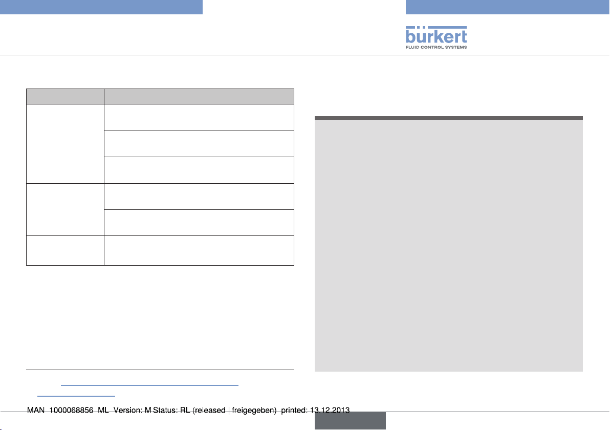
Typ 2035 / 3236
Störungen
14. STÖRUNGEN
Störung Ursache /Beseitigung
Antrieb schaltet
nicht.
Ventil ist nicht
dicht.
Durchflussmenge
verringert.
Tab. 5: Störungen
4) siehe „Bild 24: Pneumatischer Anschluss, Einbau
Näherungsschalter“ .
Steuerluftanschluss vertauscht
Steuerluftanschlüsse prüfen
Steuerdruck zu gering
Siehe Druckangabe auf dem Typschild.
Mediumsdruck zu hoch
Siehe Druckangabe auf dem Typschild.
Mediumsdruck zu hoch
Siehe Druckangabe auf dem Typschild.
Steuerdruck zu gering
Siehe Druckangabe auf dem Typschild.
Membran ausgebeult
→ Membran austauschen.
4)
15. TRANSPORT, LAGERUNG,
VERPACKUNG
HINWEIS!
Transportschäden.
Unzureichend geschützte Geräte können durch den Transport
beschädigt werden.
▶ Gerät vor Nässe und Schmutz geschützt in einer stoßfesten Ver-
packung transportieren.
▶ Eine Über- bzw. Unterschreitung der zulässigen Lagertemperatur
vermeiden.
▶ Pneumatischen Anschlüsse mit Schutzkappen vor Beschädigun-
gen schützen.
Falsche Lagerung kann Schäden am Gerät verursachen.
▶ Gerät trocken und staubfrei lagern.
▶ Lagertemperatur 0 … +60 °C.
Lagerung mit festgezogenen Gehäuseschrauben kann zu
bleibenden Verformungen der Membran führen.
▶ Gehäuseschrauben bei längerer Einlagerung lockern.
Umweltschäden durch von Medien kontaminierte Geräteteile.
▶ Gerät und Verpackung umweltgerecht entsorgen.
▶ Geltende Entsorgungsvorschriften und Umweltbestimmungen
einhalten.
deutsch
81
Page 82

Typ 2035 / 3236
82
deutsch
Page 83
Type 2035 / 3236
Sommaire
1. À PROPOS DE CE MANUEL ................................................................... 85
1.1. Symboles..........................................................................................85
1.2. Définition du terme / abréviation .................................................85
2. UTILISATION CONFORME.......................................................................86
2.1. Restrictions ......................................................................................86
3. CONSIGNES DE SÉCURITÉ FONDAMENTALES .........................86
3.1. Utilisation dans la zone Ex ............................................................87
3.2. Conditions particulières ................................................................89
4. INDICATIONS GÉNÉRALES .................................................................... 89
4.1. Adresse ............................................................................................89
4.2. Garantie légale ................................................................................89
4.3. Informations sur Internet ...............................................................89
4.4. Marques déposées ........................................................................90
5. DESCRIPTION DU PRODUIT ................................................................. 90
5.1. Description générale .....................................................................90
5.2. Variantes de l'appareil ...................................................................90
5.3. Vidange automatique des vannes ............................................... 92
5.4. Symboles de vanne et diagrammes d'écoulement .................93
5.5. Identification de la vanne ..............................................................95
5.6. Utilisation prévue ............................................................................97
6. STRUCTURE ET MODE DE FONCTIONNEMENT ........................ 97
6.1. Structure du type 2035 ................................................................97
6.2. Structure du type 3236 ................................................................98
7. CARACTÉRISTIQUES TECHNIQUES ................................................99
7.1. Conformité .......................................................................................99
7.2. Normes .............................................................................................99
7.3. Homologations ................................................................................99
7.4. Plaque signalétique........................................................................99
7.5. Conditions d'exploitation ..............................................................99
7.6. Caractéristiques mécaniques ......................................................99
7.7. Données fluidiques ..................................................................... 101
8. MONTAGE ..................................................................................................... 103
8.1. Consignes de sécurité ...............................................................103
8.2. Avant le montage .........................................................................103
8.3. Montage ........................................................................................104
8.4. Raccordement pneumatique (seulement type 2035) ......... 105
8.5. Montage du détecteur de proximité inductif ......................... 106
9. UTILISATION ET FONCTIONNEMENT............................................107
9.1. Consignes de sécurité ...............................................................107
9.2. Type 2035 - Actionnement pneumatique ..............................107
9.3. Type 3236 - Actionnement manuel .........................................108
10. COMMANDE ÉLECTRIQUE ................................................................ 108
11. DÉMONTAGE ............................................................................................ 108
12. MAINTENANCE, NETTOYAGE .......................................................... 109
12.1. Consignes de sécurité .............................................................109
12.2. Intervalle d'entretien..................................................................109
12.3. Travaux de maintenance ..........................................................109
12.4. Nettoyage ................................................................................... 110
français
83
Page 84

13. MAINTENANCE ........................................................................................ 111
13.1. Consignes de sécurité .............................................................111
13.2. Remplacement de la membrane ............................................111
14. PIÈCES DE RECHANGE ...................................................................... 120
14.1. Tableau de commande............................................................. 120
15. PANNES ....................................................................................................... 121
16. TRANSPORT, STOCKAGE, EMBALLAGE ................................... 121
Type 2035 / 3236
84
français
Page 85

Type 2035 / 3236
À propos de ce manuel
1. À PROPOS DE CE MANUEL
Ce manuel décrit le cycle de vie complet de l'appareil. Conservez ce
manuel de sorte qu'il soit accessible à tout utilisateur et à disposition
de tout nouveau propriétaire.
AVERTISSEMENT !
Ce manuel contient des informations importantes sur la
sécurité.
Le non-respect de ces consignes peut entraîner des situations
dangereuses.
▶ Ce manuel doit être lu et compris.
1.1. Symboles
DANGER !
Met en garde contre un danger imminent.
▶ Le non-respect peut entraîner la mort ou de graves blessures.
AVERTISSEMENT !
Met en garde contre une situation éventuellement
dangereuse.
▶ Risque de blessures graves, voire la mort en cas de non-respect.
ATTENTION !
Met en garde contre un risque possible.
▶ Le non-respect peut entraîner des blessures moyennes ou légères.
REMARQUE !
Met en garde contre des dommages matériels.
▶ L'appareil ou l'installation peut être endommagé(e) en cas de
non-respect.
désigne des informations complémentaires importantes, des
conseils et des recommandations.
renvoie à des informations dans ce manuel ou dans d'autres
documentations.
▶ Identifie une instruction visant à éviter un danger.
→ Identifie une opération que vous devez effectuer.
1.2. Définition du terme / abréviation
Le terme « appareil » utilisé dans ce manuel désigne toujours la
vanne à membrane multi-voies Robolux type 2035 / 3236.
Le terme « vanne à membrane » utilisé dans ce manuel désigne toujours la vanne à membrane multi-voies Robolux type 2035 / 3236.
L’abréviation « Ex » utilisé dans ce manuel désigne toujours «présentant des risques d‘explosion ».
français
85
Page 86

Type 2035 / 3236
Utilisation conforme
2. UTILISATION CONFORME
L'utilisation non conforme de la vanne à membrane multivoies Robolux 2035 / 3236 peut présenter des risques pour
les personnes, les installations proches et l'environnement.
L'appareil a été conçu pour commander le débit de fluides
liquides.
▶ Lors de l'utilisation, il convient de respecter les données et condi-
tions d'utilisation et d'exploitation admissibles spécifiées dans les
documents contractuels, ce manuel et sur la plaque signalétique.
Les utilisations prévues sont reprises au chapitre « 5. Description
du produit ».
▶ L'appareil peut être utilisé uniquement en association avec les
appareils et composants étrangers recommandés et homologués
par Bürkert.
▶ Les conditions pour l'utilisation sûre et parfaite sont un transport, un
stockage et une installation dans les règles ainsi qu'une utilisation
et une maintenance parfaites.
▶ Veillez à ce que l'utilisation de l'appareil soit toujours conforme.
2.1. Restrictions
Lors de l'exportation du système/de l'appareil, veuillez respecter les
restrictions éventuelles.
3. CONSIGNES DE SÉCURITÉ
FONDAMENTALES
Ces consignes de sécurité ne tiennent pas compte
• des hasards et des événements pouvant survenir lors du montage,
de l'exploitation et de l'entretien des appareils.
• des prescriptions de sécurité locales que l'exploitant est tenu de
faire respecter entre autres par le personnel chargé du montage.
DANGER !
Risque de blessures dû à la présence de haute pression dans
l‘installation/l‘appareil.
▶ Avant de travailler sur l’installation ou l’appareil, il convient de
couper la pression et de purger l’air des conduites/de les vider.
Risque de choc électrique.
▶ Avant de travailler sur l’installation ou l’appareil, couper la tension
et empêcher toute remise sous tension par inadvertance.
▶ Respecter les réglementations en vigueur pour les appareils élec-
triques en matière de prévention des accidents et de sécurité.
AVERTISSEMENT !
Risque de blessures à l'ouverture de l'actionneur.
L'actionneur contient des ressorts tendus. Il y a risque de blessures à l'ouverture de l'actionneur suite à la détente des ressorts.
▶ L'ouverture de l'actionneur n'est pas autorisée.
86
français
Page 87

Type 2035 / 3236
Consignes de sécurité fondamentales
ATTENTION !
Risque de brûlures.
La surface de l'appareil peut devenir brûlante en fonctionnement continu.
▶ Ne pas toucher l'appareil à mains nues.
Situations dangereuses d'ordre général.
Pour prévenir les blessures, respectez ce qui suit :
▶ L'actionnement par inadvertance de l'installation ne doit pas être
possible.
▶ Les travaux d'installation et de maintenance doivent être effectués
uniquement par des techniciens qualifiés et habilités disposant
de l'outillage approprié.
▶ Après une interruption de l'alimentation électrique ou pneumatique,
un redémarrage défini ou contrôlé du processus doit être garanti.
▶ L'appareil doit être utilisé uniquement en parfait état et en res-
pectant ce manuel.
▶ Les règles générales de la technique s'appliquent pour planifier
l'utilisation et utiliser l'appareil.
Pour prévenir les dommages matériels, respectez ce qui suit :
▶ Alimenter les raccords de fluides seulement avec les liquides de
débit énumérés au chapitre « 7. Caractéristiques techniques ».
▶ Ne pas soumettre le corps à des contraintes mécaniques (par
ex. en y déposant des objets sur le corps ou en l'utilisant comme
marche-pied).
▶ Ne pas entreprendre de modifications à l'extérieur des vannes. Ne
pas laquer les pièces du corps ni les vis.
3.1. Utilisation dans la zone Ex
L’abréviation « Ex » : voir chapitre « 1.2. Définition du terme / abréviation »
3.1.1. Consignes de sécurité
En cas d'utilisation en zones Ex (gaz) 1 et 2,
zones (poussière) 21 et 22, s'applique :
L'actionneur de la vanne est approprié comme appareil de catégorie 2
pour zone 1 & 21, équipement non électrique.
DANGER !
Risque d'explosion dû à la charge électrostatique.
Des charges électrostatiques peuvent se produire au niveau de la
membrane de vanne en fonction de la conductibilité du fluide et en
cas d'utilisation de corps en plastique
Pour empêcher les charges électrostatiques dans la fluidique, il convient
de respecter les consignes suivantes (selon IEC 60079-32-1):
• (1) Les fluides d’une conductibilité ≤ 100 pS/m doivent être utilisés
uniquement en l’absence de vitesses d’écoulement > 1 m/s ou si
tout fonctionnement à sec de la tuyauterie est exclu grâce à une
surveillance appropriée.
• (2) Les fluides d’une conductibilité > 100 pS/m et ≤ 1000 pS/m
doivent être utilisés uniquement s’il s’agit de liquides sans particules, de vapeur d’eau ou de gaz/vapeurs purs ou si les consignes
reprises sous (1) sont respectées.
• (3) Les fluides d’une conductibilité > 1000 pS/m ne sont soumis
à aucune limitation
français
87
Page 88

Type 2035 / 3236
Consignes de sécurité fondamentales
Autres instructions :
▶ L‘utilisateur doit garantir que l‘appareil sera utilisé uniquement dans
la zone 1/21 ou 2/22.
▶ L’installation d’indicateurs de position peut restreindre l’utilisation
dans une atmosphère explosive. Respecter les manuels de l'indicateur de retour.
▶ Contrôler l'homologation des produits de nettoyage pour atmos-
phère explosible.
3.1.2. Température du fluide
DANGER !
▶ Un risque supplémentaire d'explosion peut survenir en cas d'uti-
lisation de fluides explosifs
▶ La classe de température T3 / 200°C (poussières) s'applique
lorsque des températures de fluide situées entre 130°C et 150°C
sont utilisées.
Température du fluide La température du fluide ne doit pas
dépasser la classe de température visée.
3.1.3. Marquage de la zone Ex et
avertissements
Type 2035
PTB 13 ATEX D103 X
II 2G c IIC T6
II 2D c T85°C
Warning:
Not valid when Non-Ex devices added.
Do not open actuator. Spring loaded cover.
Clean the surface with appropriate
cleaning agent only!
Fig. 1 : Type 2035 Marquage de la zone explosible et
avertissements
Type 3236
PTB 13 ATEX D103 X
II 2G c IIC T6
II 2D c T85°C
Caution:
Clean the surface with appropriate
cleaning agent only!
88
Fig. 2 : Type 3236 Marquage de la zone explosible et
avertissements
français
Page 89

Type 2035 / 3236
Indications générales
La marquage Ex n'est pas valable si des appareils non Ex
sont ajoutés.
3.2. Conditions particulières
→ Pour assurer la compensation de potentiel, mettre le corps de
vanne à la terre sur la tuyauterie au moyen d‘un raccordement
conducteur.
DANGER !
Risque d'explosion dû à la charge électrostatique.
Il y a risque d'explosion en cas de décharge soudaine d'appareils
ou de personnes chargés d'électricité statique dans la zone explosible (zone Ex).
▶ S'assurer par des mesures appropriées, qu'il ne peut y avoir de
charges électrostatiques dans la zone explosible (voir aussi « 3.1.
Utilisation dans la zone Ex »).
▶ Ne nettoyer la surface de l'appareil que par un essuyage léger
avec un chiffon humide ou antistatique.
▶ Mettre à la terre l'actionneur et le corps de vanne.
▶ En cas d'utilisation de corps en plastique, mettre l'actionneur
séparément à la terre.
Plage de température ambiante : -10 °C ≤ Tamb ≤ 60 °C
4. INDICATIONS GÉNÉRALES
4.1. Adresse
Allemagne
Bürkert Fluid Control Systems
Sales Center
Christian-Bürkert-Str. 13-17
D-74653 Ingelfingen
Tél. + 49 (0) 7940 - 10 91 111
Fax + 49 (0) 7940 - 10 91 448
E-mail: info@de.buerkert.com
International
Les adresses se trouvent aux dernières pages du manuel d'utilisation
imprimé.
Elles sont également disponibles sur internet sous :
www.burkert.com
4.2. Garantie légale
La condition pour bénéficier de la garantie légale est l'utilisation
conforme de la vanne à membrane dans le respect des conditions
d'utilisation spécifiées.
4.3. Informations sur Internet
Vous trouverez sur Internet les manuels et fiches techniques relatifs au
type 2035 / 3236 : www.buerkert.fr
français
89
Page 90
Type 2035 / 3236
Description du produit
4.4. Marques déposées
Les marques mentionnées sont des marques déposées des sociétés /
associations / organisations concernées :
PFR 91 Solvey Solexis Inc.
PFA DuPont Performances Elastomers
Inbus Textron Verbindungstechnik GmbH & Co. oHG
5. DESCRIPTION DU PRODUIT
5.1. Description générale
Les vannes à membrane multi-voies Robolux1) à actionnement pneumatique ou manuel ont été conçues pour contrôler des fluides ultrapurs, stériles, agressifs ou abrasifs. Elles permettent de collecter,
vider ou distribuer de manière optimale des fluides de process
critiques.
Respecter les consignes pour l'utilisation en zone protégée
contre l'explosion. Voir chapitre « 3.1 ».
1) La vanne à membrane multi-voies Robolux sera désignée
dans la suite de ce document de manière abrégée par vanne à
membrane.
5.2. Variantes de l'appareil
La vanne à membrane est disponible en deux variantes par :
vanne à actionnement pneumatique ou vanne à actionnement manuel.
Les caractéristiques modulaires de la vanne à membrane lui permettent de s'adapter aux conditions d'utilisation les plus diverses.
Trois tailles (RV50, RV70, RV110) sont disponibles en fonction de la
taille de raccordement des vannes à membrane.
Le corps d'actionneur est fabriqué à partir d'un bloc en acier inoxydable. Des corps de vanne en plastique (PVDF ou PP) sont proposés pour certaines conditions d'utilisation.
90
français
Page 91
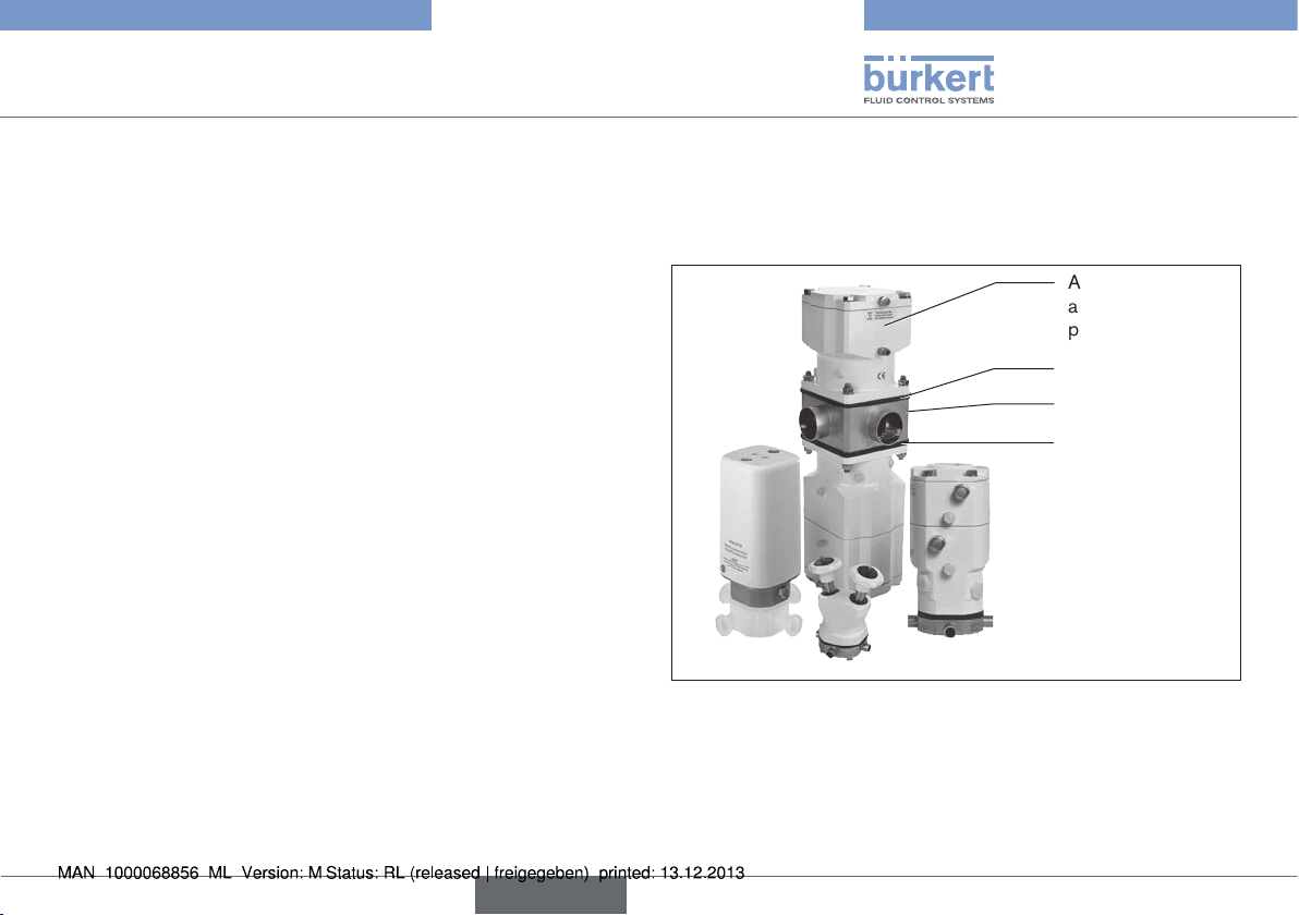
Type 2035 / 3236
Description du produit
Des membranes de qualité élevée séparent complètement le fluide
critique de l'actionneur.
Selon sa fonction, la vanne peut disposer de un, deux ou trois
actionneurs.
Les vannes à membrane pouvant réaliser une multitude de fonctions,
leur configuration est très variée. Par exemple, selon leur fonction :
• les vannes peuvent varier dans l'actionneur,
• les actionneurs peuvent disposer de un ou deux pistons de commande, qui fonctionnent indépendamment l'un de l'autre,
• des actionneurs pneumatiques peuvent être équipés de détecteurs de proximité inductifs pour l'interrogation des différentes
positions de commutation.
5.2.1. Vanne à membrane à actionnement
pneumatique type 2035
La vanne dispose d'un ou de deux actionneurs, piloté(s) par de l'air
comprimé.
Actionneur à
actionnement
pneumatique
Membrane
Corps de vanne
Membrane
Fig. 3 : Vanne à membrane à actionnement pneumatique,
structure et description
français
91
Page 92
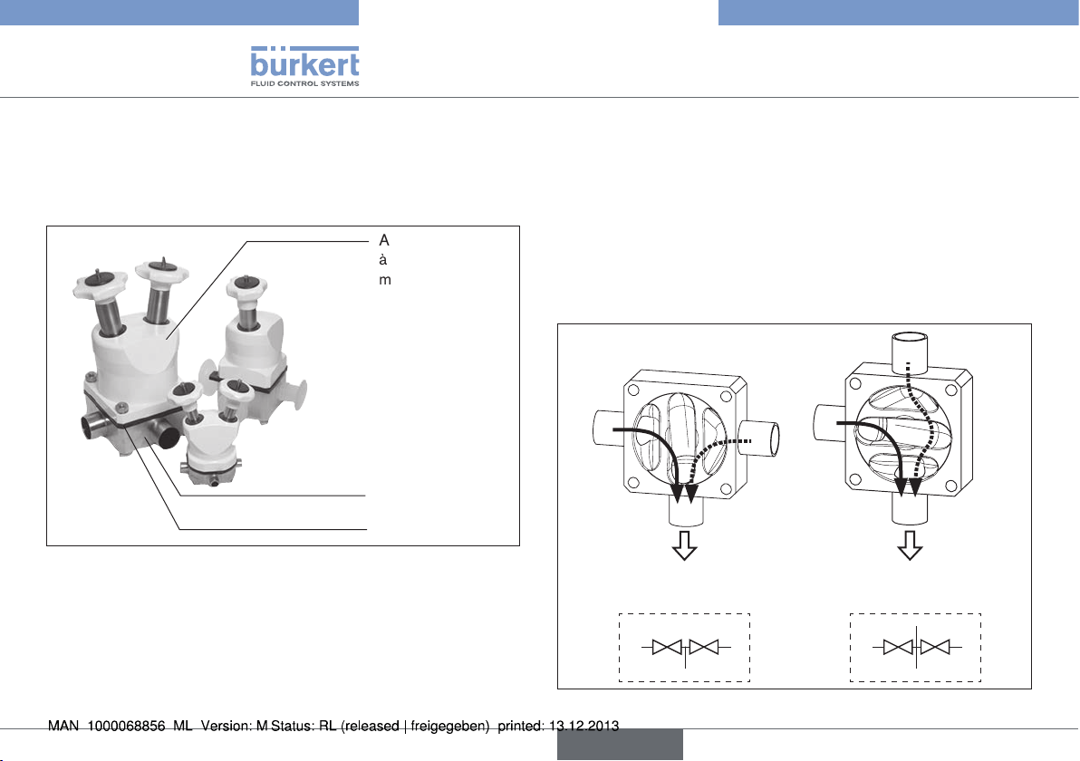
Type 2035 / 3236
Description du produit
5.2.2. Vanne à membrane à actionnement
manuel type 3236
La vanne est actionnée manuellement.
Actionneur
à actionnement
manuel
Corps de vanne
Membrane
Fig. 4 : Vanne à membrane à actionnement manuel, structure et
description
5.3. Vidange automatique des vannes
La vidange automatique s'effectue différemment selon les types
de vanne. Il est très important de connaître les voies de passage
de chaque vanne avant de sélectionner le port / le raccordement
(marqué A, B, C ou D) pour la vidange.
En cas de questions, adressez-vous à votre distributeur
Bürkert ou à notre Sales Center, e-mail : info@de.buerkert.com
Les exemples suivants expliquent la vidange pour les types de
vannes 3C2S / 4C2S et 4C4S DFP.
Positions de montage pour la vidange :
A
B
3C2S / 4C2S
raccord de vidange B (D)
A
C
C
B
raccord de vidange C (A)
A
C
3C2S / 4C2S
A
D
C
92
B
Fig. 5 : Vidange automatique - 3C2S / 4C2S
français
B
Page 93

Type 2035 / 3236
Description du produit
Positions de montage pour la vidange :
C
D
A
4C4S DFP
raccord de vidange
A (C)
Fig. 6 : Vidange automatique 4C4S DFP
B
A
A
D
B
D
B
4C4S DFP
raccord de vidange
B (C)
C
5.4. Symboles de vanne et
diagrammes d'écoulement
3 raccords, 2 sièges
3C2S
C
Siège
U2
Siège
U2
C
4 raccords, 2 sièges
4C2S
C
A
A
C
B
D
C
B
A
Siège
Fig. 7 : Symboles de vanne et diagrammes d'écoulement - 3C2S
A
Siège
U1
U1
B
D
B
français
Fig. 8 : Symboles de vanne et diagrammes d'écoulement - 4C2S
93
Page 94

Type 2035 / 3236
Description du produit
3 raccords, 3 sièges
3C3S
vue du dessus vue du dessous
C
Siège
U1
D
Siège
U2
A
Siège
L1
D
C
C
A
D
A
Fig. 9 : Symboles de vanne et diagrammes d'écoulement - 3C3S
4 raccords, 3 sièges
4C3S
vue du dessus vue du dessous
D
D
D
A C
Siège
U1
Siège
B
C A
Siège
U2
L1
A
B
C
B
Fig. 10 : Symboles de vanne et diagrammes d'écoulement - 4C3S
4 raccords, 3 sièges
4C3S BD vanne à filtre
vue du dessus vue du dessous
A
A
A
B
Siège
U1
C
Siège
U2
D
D
C
Siège
L2
B
B
D
C
Fig. 11 : Symboles de vanne et diagrammes
d'écoulement - 4C3S BD
4 raccords, 4 sièges
4C4S
vue du dessus vue du dessous
A
Siège
U1
D
C
C
Siège
B
U2
Siège
L1
D
A
Siège
B
L2
D
A
C
B
Fig. 12 : Symboles de vanne et diagrammes d'écoulement - 4C4S
94
français
Page 95

Type 2035 / 3236
Description du produit
4 raccords, 4 sièges
4C4S DFP vanne double de débit
vue du dessus vue du dessous
D
A
Siège
Fig. 13 : Symboles de vanne et diagrammes
Siège
B
U1
d'écoulement - 4C4S DFP
vue du dessus vue du dessous
A
B1
U1
C
C
Siège
U2
C
Siège
U2
Siège
4 raccords, 5 sièges
4C5S vanne de chromatographie
C
Siège
L1
L1
B1
D
B
B2
A
Siège
L2
A
Siège
L2
5.5. Identification de la vanne
Marquage de la zone explosible et
avertissements
D
A
B1
A
B2
C
B
Inscription du corps de vanne
C
Fig. 15 : Identification de la vanne
Plaque signalétique
Identification de
l'orientation de
l'actionneur
Identification des raccords
de conduite
Diamètre nominal et
dimensions de raccord
matériau, charge, ordre de
fabrication et n° de série
Fig. 14 : Symboles de vanne et diagrammes d'écoulement - 4C5S
français
95
Page 96

Type 2035 / 3236
Description du produit
5.5.1. Plaque signalétique
Taille
Type
2035 RV50 4C 4S-DFP
EPDM-cus D11 -D11
Weld end 19,05x1,65
Pilot 4,2-10 bar
Pmed 10bar
Made in Germany
12345678
Numéro d'identification
Fig. 16 : Plaque signalétique type 2035
Robolux
3236 RV50 4C 4S-DFP
EPDM-cus D44 -D44
Weld end 19,05x1,65
Pmed 10bar
Made in Germany
12345678
Fig. 17 : Plaque signalétique type 3236
W14UN
W14UN
Forme de construction
Matériau de la membrane -
Actionneur 1 -
Actionneur 2
Type de raccord -
dimensions de raccordement
Pression de pilotage
Pression max. du fluide
Date de construction
Type - Taille - Forme de
construction
Matériau de la membrane -
Actionneur 1 -
Actionneur 2
Type de raccord -
dimensions de raccordement
Pression max. du fluide
Date de construction
Numéro d'identification
5.5.2. Marquage de la zone explosible et
avertissements
Voir chapitre « 3.1.3. Marquage de la zone Ex et avertissements ».
5.5.3. Identification des raccords de
conduite
Tous les raccords de conduite sont dotés de lettres, correspondant
aux diagrammes d'écoulement (voir chapitre « 5.4. Symboles de
vanne et diagrammes d'écoulement »).
5.5.4. Identification de l'orientation de
l'actionneur
L'actionneur est doté d'un marquage dans la zone de raccordement
A pour faciliter le montage correct des paliers.
Fig. 18 : Identification de l'orientation de l'actionneur
96
français
Page 97

Type 2035 / 3236
Structure et mode de fonctionnement
5.6. Utilisation prévue
La vanne à membrane est conçue pour l'utilisation avec des fluides
encrassés et agressifs n'attaquant pas les matériaux du corps et du joint.
Respectez la plage de pression maximale indiquée sur la
plaque signalétique.
• Fluides très purs, stériles, agressifs ou abrasifs.
• Fluides à viscosité élevée.
Respecter les consignes pour l'utilisation en zone protégée
contre l'explosion. Voir chapitre « 3.1 ».
5.6.1. Domaines d'application
Par ex. construction d'installations
industrie agro-alimentaire
stations de remplissage
technique des procédés chimiques
pharmacie
6. STRUCTURE ET MODE DE
FONCTIONNEMENT
6.1. Structure du type 2035
La vanne à membrane est composée d'un d'actionneur par piston à
actionnement pneumatique, d'une membrane et d'un corps de vanne
multi-voies.
Capot de l'actionneur
Silencieux
Raccord d'air de
pilotage
Corps de l'actionneur
Cache position
détecteur de proximité
Cache vis pièce de
pression
Membrane
Corps de vanne
Vis / écrous du corps
Fig. 19 : Vanne à membrane commandée par piston, structure et
description
français
97
Page 98

Type 2035 / 3236
1(P)
2(A)
1(P)
2(B)
Structure et mode de fonctionnement
6.1.1. Actionneur
L'actionneur possède deux chambres d'actionneur, qui peuvent être
pilotées indépendamment l'une de l'autre et qui agissent respectivement sur un siège du corps (actionneur double). Dans le cas d'un
actionneur simple, la vanne est équipée d'une seule chambre avec
des pièces internes de fonctionnement.
L'effet de ressort (CFA, NF) ou la pression de pilotage pneumatique
(CFB, NO) génère la force de fermeture sur l'actionneur.
La force est transmise respectivement par une tige reliée au
piston d'actionneur, à la pièce de pression correspondante et à la
membrane.
6.1.2. Fonctions (CF)
Fonction A, NF (CFA)
En position de repos, fermée par
ressort
Fonction B, NO (CFB)
En position de repos, ouverte par
ressort
6.2. Structure du type 3236
La vanne à membrane est composée d'un d'actionneur à actionnement manuel, d'une membrane et d'un corps de vanne multi-voies.
Volant
Corps de
l'actionneur
Membrane
Corps de vanne
Vis du corps
Fig. 20 : Vanne à membrane à actionnement manuel, structure et
description
6.2.1. Actionneur
L'actionneur possède deux volants qui peuvent être actionnés indépendamment l'un de l'autre et qui agissent respectivement sur un
siège du corps (actionneur double). Dans le cas d'un actionneur
simple, la vanne est équipée d'un seul côté d'actionneur.
La force est transmise par respectivement une tige reliée au volant, à
la pièce de pression correspondante et à la membrane.
98
français
Page 99

Type 2035 / 3236
Caractéristiques techniques
7. CARACTÉRISTIQUES
TECHNIQUES
7.1. Conformité
Les vannes à membrane de type 2035 et de type 3236 sont conformes
aux directives CE conformément à la déclaration de conformité CE.
7.2. Normes
Les normes utilisées, avec lesquelles la conformité avec les directives
CE sont prouvées, figurent dans l'attestation CE de type et/ou la
déclaration de conformité CE.
7.3. Homologations
L'appareil est conçu pour être utilisé conformément à la directive
ATEX 94/9/CE, catégorie 2G/D, zones 1 et 21.
Respecter les consignes pour l'utilisation en zone protégée
contre l'explosion. Voir chapitre « 3.1 ».
Corps de vanne Acier inoxydable : EN ISO 10204 3.1
Polypropylène : USP VI (matériau PR)
Membrane FDA CFR 177.2600 pour EPDM, FKM et silicone
FDA CFR 177.1550 pour PFA
USP VI pour EPDM, PFA/EPDM, silicone et
PFR 91
7.4. Plaque signalétique
Voir chapitre « 5.5. Identification de la vanne ».
7.5. Conditions d'exploitation
Respectez la plage de pression admissible indiquée sur la
plaque signalétique de l'appareil.
Température ambiante -10 ... +60 °C
températures plus élevées sur demande
Température de service max. +85 °C
Humidité relative de l'air max. 80 % (sans condensation)
7.6. Caractéristiques mécaniques
Dimensions voir fiche technique
Matériaux
Matériau du corps Acier inoxydable : 1.4435/316L
(autres matériaux sur demande)
PP (polypropylène ultra pur)
PP (polypropylène USP VI)
PVDF (fluorure de polyvinylidène)
Membrane EPDM, silicone, PFA/EPDM, FKM, PFR 91
Actionneur aluminium avec revêtement par
poudre époxy
Corps en PP (seulement type 2035 RV50)
français
99
Page 100
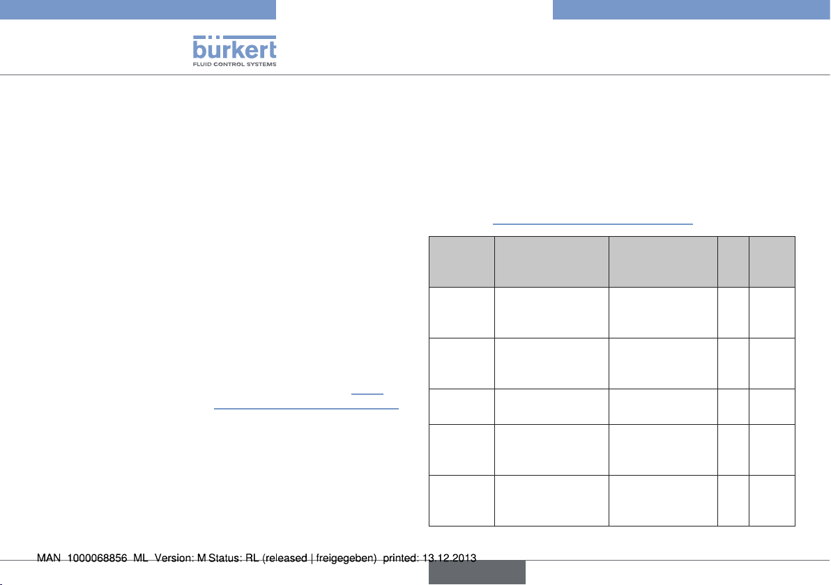
Type 2035 / 3236
Caractéristiques techniques
Raccordements
Raccords de conduite Raccord à souder DIN EN ISO
1127
(ISO 4200), DIN 11850 série 2,
ASME BPE
SMS 3008, BS4825
(autres raccords à souder, Clamp
et visseries stériles sur demande)
Raccord à l'air de pilotage G1/8
Qualité de surface intérieure Ra 0,5 µm passivé
extérieure Ra 3,2 µm grenaillé à
la bille de verre
option électropoli
(autres qualités de surface sur
demande)
Position de montage au choix, de préférence raccord
B vers le bas ; pour la vidange
automatique voir chapitre « 5.3.
Vidange automatique des vannes »
Durée de vie
La durée de vie de l'appareil dépend fortement des conditions
d'utilisation. La durée de vie de la membrane dépend fortement des
conditions de service, comme par exemple le fluide, les températures, la fréquence de commutation, la pression etc.
7.6.1. Membrane
La membrane assure l'étanchéité de la vanne. Elle doit être choisie
avec soin. La sélection du matériau doit être appropriée au fluide de
process, à la température et aux conditions de service (par exemple à
la pression de service, à la fréquence de commutation etc.).
Le tableau suivant indique les matériaux standards.
Conformité à FDA CFR 21 §177.2600 ou §177.1550 et certificat
USP VI voir « Tab. 1 : Matériaux de la membrane ».
Matériau
de la
membrane
EPDM éthylène-propylène-
PFA /
EPDM
FKM caoutchouc synthé-
silicone caoutchouc de
PFR 91 PFR 91
Tab. 1 : Matériaux de la membrane
Description du
matériau
caoutchouc vulcanisé au péroxyde
PFA
vulcanisé sur
EPDM
tique fluorocarboné
silicone stabilisé
au platine
caoutchouc synthétique fluorocarboné
Application FDA USP VI
produits chimiques
oxydants, vapeur
et eau chaude
les principaux produits chimiques et
acides
acides et huiles
minérales
huiles aliphatiques x x
huiles aliphatiques x
x x
x x
x
100
français
 Loading...