

Burkert 3233, 3234, 3235 Instruction Manual
© Bürkert 2004 Subject to technical change without notice
3233-3234-3235
HAND-OPERATED DIAPHRAGM VALVES
Instruction Manual
Operating Instructions 0811/06_EU-ML _00440910
2
INTRODUCTION
ENGLISH
3233-3234-3235
Table of contents
INTRODUCTION............................................................................................................................................. 2
1.1 GENERAL SAFETY INSTRUCTIONS......................................................................................... 3
1.2 DESCRIPTION OF THE DIAPHRAGM VALVE.......................................................................3
INSTALLATION................................................................................................................................................ 4
2.1 RECOMMENDATIONS FOR INSTALLING THE VALVE..................................................... 4
2.1.1 Before installation............................................................................................................................................. 4
2.1.2 During installation.............................................................................................................................................4
2.1.3 Installation of the valve 3233 for self-draining ........................................................................ 4
2.1.4 Installation of a tank outlet valve 3235 .......................................................................................... 5
TECHNICAL DATA.........................................................................................................................................6
3.1 GENERAL SPECIFICATIONS ........................................................................................................6
3.2 MANUAL ACTUATOR SPECIFICATIONS.................................................................................6
3.3 DIAPHRAGM SPECIFICATIONS..................................................................................................6
3.4 VALVE BODY SPECIFICATIONS ................................................................................................. 7
MAINTENANCE............................................................................................................................................... 8
4.1 MAINTENANCE AND STORING................................................................................................... 8
4.1.1 Maintenance and order codes of the spare parts.................................................................. 8
4.1.2 Storing........................................................................................................................................................................ 8
4.2 DISMANTLING THE DIAPHRAGM VALVE ..............................................................................9
3
INTRODUCTION
ENGLISH
3233-3234-3235
1.1 GENERAL SAFETY INSTRUCTIONS
- Please verify that the product is complete and free from any damage.
- It is the customer’s responsibility to select an appropriate valve for the
application, ensure the unit is installed correctly and maintain the components.
- This product should only be installed and repaired by specialist staff using the
correct tools.
- Please observe the relevant safety regulations throughout the operation,
maintenance and repair of the product.
- If these instructions are ignored, no liability will be accepted and the guarantee
on the device and accessories will be invalid.
If the valve is used with dangerous fluids, insert the valve into the
process according to the legal security standards.
1.2 DESCRIPTION OF THE DIAPHRAGM VALVE
The diaphragm valve 3233, 3234 or 3235 has been designed to control the flow of fluids,
even charged or aggressive.
The compact design of this valve makes it possible to use it in processes where the space
requirement is very small.
This 2/2-way valve is made up of :
- a valve body
- a diaphragm that isolates the fluid from the atmosphere and the mechanical parts
of the top of the valve.
- an hand-operated actuator which makes it possible to control the valve opening.
- an optical position indicator indicating the valve status.
4
INSTALLATION
ENGLISH
3233-3234-3235
2.1 RECOMMENDATIONS FOR INSTALLING THE VALVE
• Insert the valve into the process according to the standard
industrial practices (preferably according to ASME or DIN 11850
standards).
• Only tighten the manual actuator by hand!
2.1.1 Before installation
- Carefully clean the pipes.
- Remove all the pressures and tensible forces exerted on the valve by the pipes.
2.1.2 During installation
- Ensure the pipes are aligned.
- If the valve body must be welded onto the pipes, dismantle the valve (see § 4.2)
to separate the actuator and the diaphragm from the body to prevent them from
any damage.
- Preferably improve the surface quality by grinding the weldings.
- Carefully clean the body before mounting back the actuator and the diaphragm
(see § 4.2).
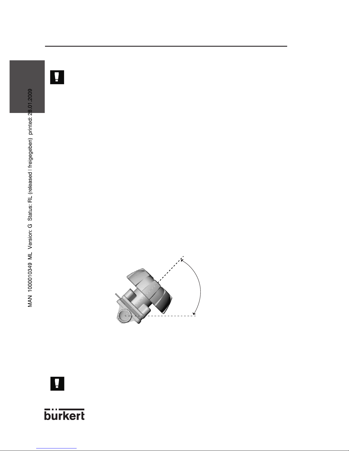
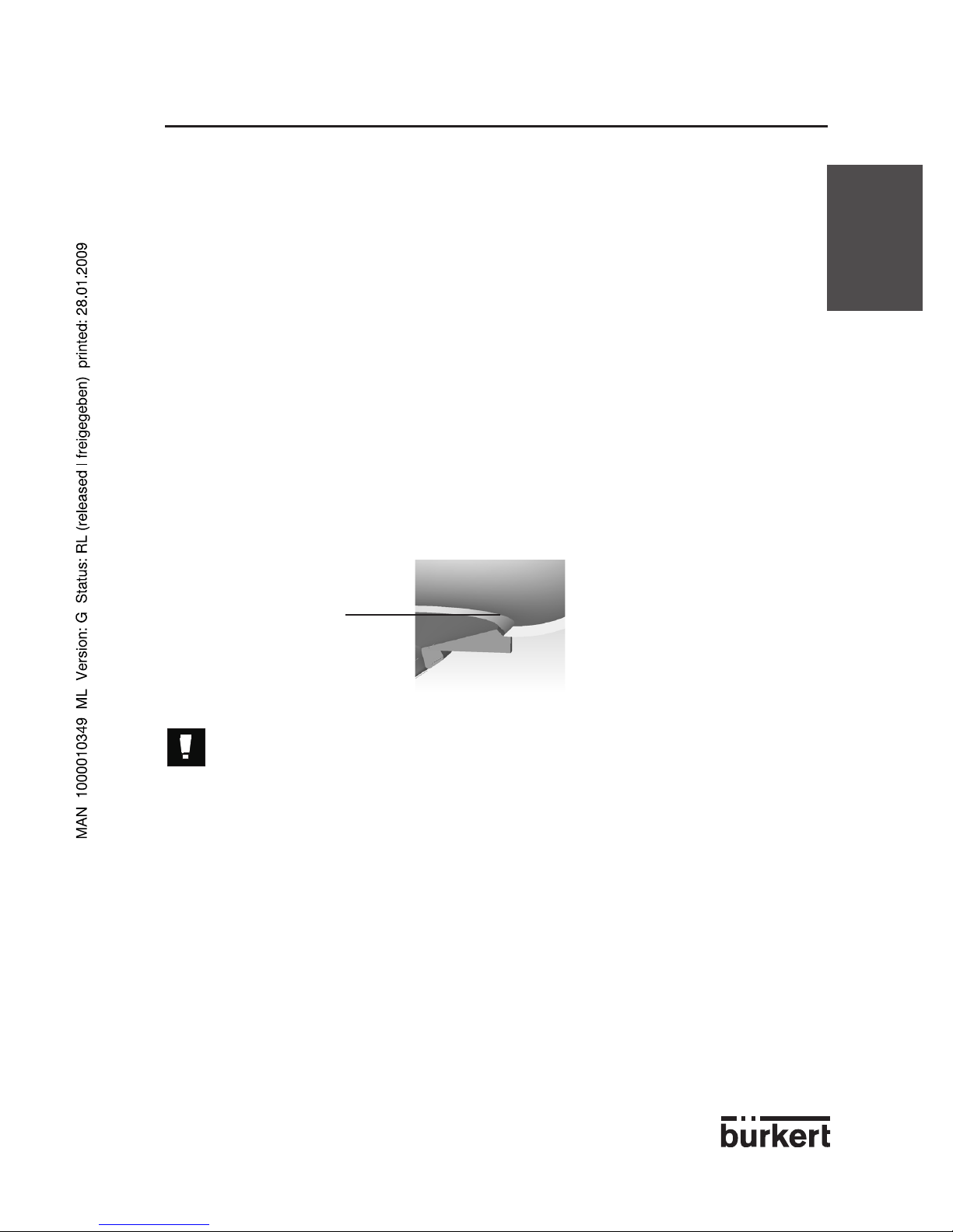
2.1.3 Installation of the valve 3233 for self-draining
- Incline the valve of 15° to 30° (depending on the DN) with respect to the
horizontal (see figure below)
- Install the pipes with a 3 to 5% minimum gradient in the direction of flow.
During the assembling of the valve in self draining position, the leakage detection hole
must be at the lowest point.
Self-draining in a process system is ultimately the responsibility of the
system designer and/or end user.
15°-30°
5
INSTALLATION
ENGLISH
3233-3234-3235
2.1.4 Installation of a tank outlet valve 3235
Refer to ASME VIII Division I «Boiler and pressure Vessel code» standard for further
information on tanks and welding recommendations.
We recommend to weld the tank outlet valve before mounting the tank. Nevertheless,
welding valves on mounted tanks remains possible if need be.
- Ensure the tank outlet valve is not in conflict with any other equipment and the
mounting and dismounting of the actuator is always possible.
- Ensure the minimum distance between two weld seams is 3 times the thickness
of the tank wall.
We recommend to weld the valve to the center of the tank outlet to optimize the draining.
- The diameter of the whole in the tank wall must be the same as the diameter of the
flange.
The Bürkert valve has two welding bevels to ease the welding and valve positionning
operations. The welding bevel is about 3 mm long. If the tank thickness is more than
3 mm, position the valve as indicated in the figure below.
Grind the tank outlet wall by hand to prepare the welding operation.
Before welding, ensure the heat number corresponds to the one
indicated on the supplied manufacturer certificate 3.1.B.
- Insert the flange inside the whole so that the surfaces of the flange and the tank outlet
are tangent.
- Tack 4 weld points and check the positionning.
- Weld continuously the internal and external parts by supplying gaz and filler
material compatible with the 316L (DIN 1.4435) stainless steel the valve is made of.
- Cool down the weld seams then polish-grind and clean them according to the current
specifications.
These instructions will help you installing the tank outlet valves and make it possible to
avoid any change in shape and stress release within the tank.
These instructions do not override the country specific legal obligations about the
accreditation of welding operators and the carrying out of welding operations.
Part to be grinded
6
SPECIFICATIONS
ENGLISH
3233-3234-3235
3.1 GENERAL SPECIFICATIONS
The main advantages of the valve are the following:
- Heat number indicated on each valve to ensure the traceability of the material.
- Any mounting position.
- Any direction of flow.
- Perfect tightness due to diaphragm.
- Self-draining (valve 3233 only, see § 2.1).
- Small space requirement.
- Flow optimized design.
- Valve inside design optimized to reduce the turbulences to the minimum.
- Minimal charge loss.
- Internal mechanism adapted to the constraints of the food and drug industry.
- Steam sterilizable.
- Autoclavable.
3.2 MANUAL ACTUATOR SPECIFICATIONS
- Material: phenylene polysulphide (PPS), stainless steel or white epoxy coated cast
iron
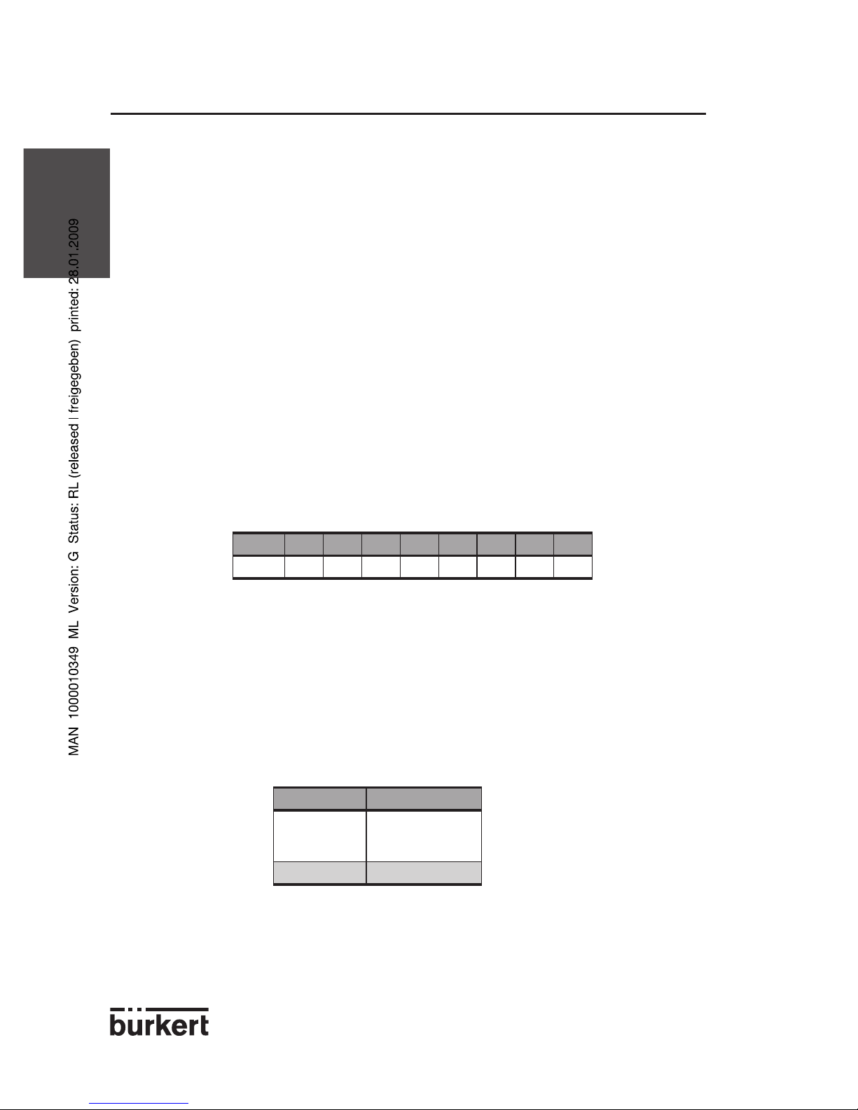
- Handwheel diameter depending on the DN:
- Ambient temperature: +5 °C to +140 °C.
3.3 DIAPHRAGM SPECIFICATIONS
- Material:
• PTFE/EPDM
• elastomer (EPDM, FPM or CSM)
- Temperature of the medium:
DN 8 15 20 25 40 50 80 100
ø [mm]
35 80 80 80 114 114 225 275
Material Temperature [°C]
PTFE ./ EPDM
EPDM
CSM
-10 to +130
FPM -5 to +150
7
SPECIFICATIONS
ENGLISH
3233-3234-3235
3.4 VALVE BODY SPECIFICATIONS
- Material:
• Forged stainless steel (DIN 1.4435 BN2 / 316L according to ASME-BPE
1997).
• Cast stainless steel (316L).
• Rolled steel (316L).
- Types of connections:
• butt-weld ends which conform to ISO 4200, SMS 3008, DIN 11850,
BS 4825-1 and JIS standards
• Clamp ends which conform to BS 4825-3, ISO 2852, DIN 32676,
SMS 3017 standards
• dairy pipe unions which conform to DIN 11851 or SMS 1145 standards
• other connections on request.
- Nominal diameter (DN): DN8 to DN100
- Temperature of the conveyed medium: depends on the diaphragm material.
- Pressure class of the valve:
• P
medium
< 10 bar for DN8 to DN40
• P
medium
< 7 bar for DN50
• P
medium
< 5 bar for DN65 to DN100
8
MAINTENANCE
ENGLISH
3233-3234-3235
4.1 MAINTENANCE AND STORING
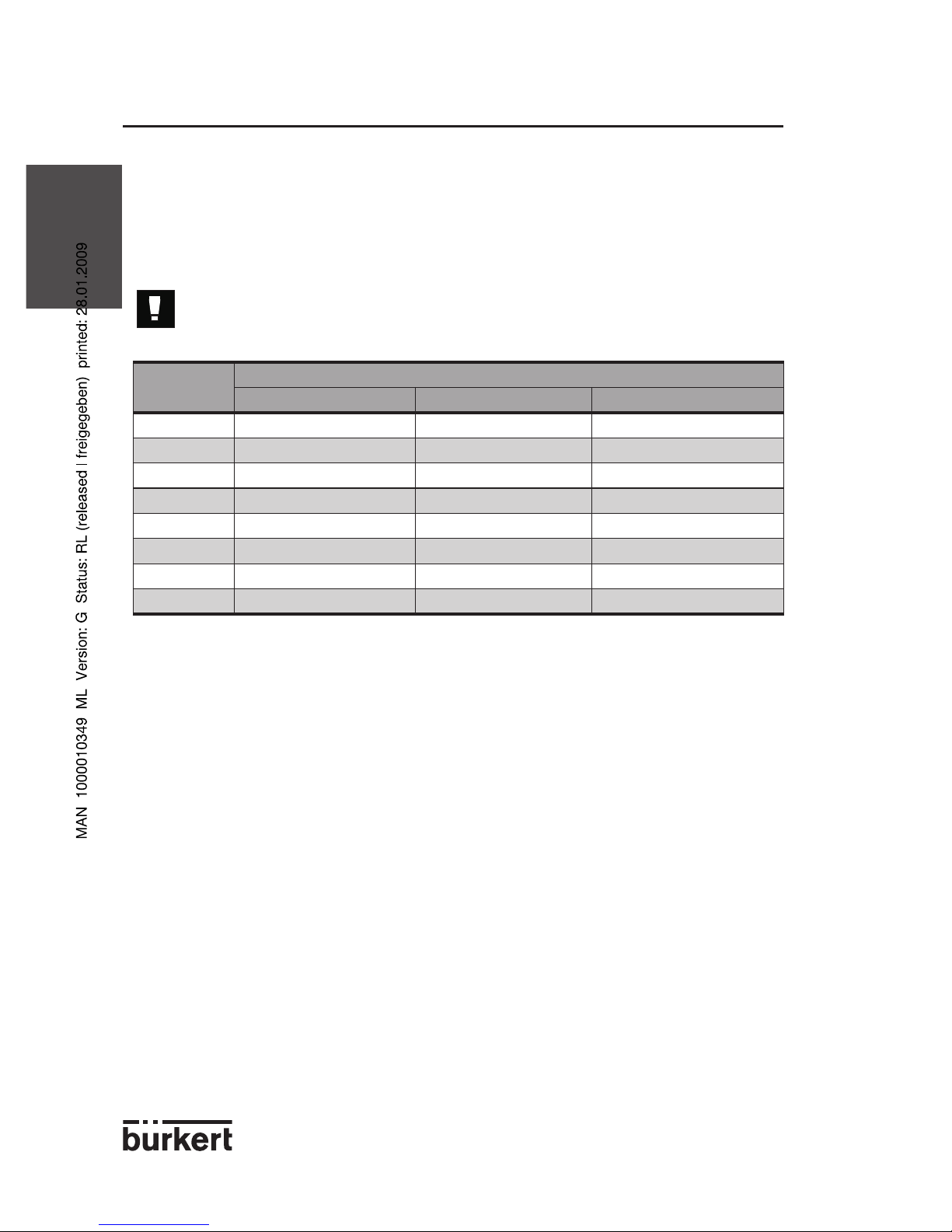
4.1.1 Maintenance and order codes of the spare parts
Regularly check if the diaphragm is not worn. Refer to the table below to have the order
code of the diaphragm corresponding to your valve (CSM diaphragms on request).
If your process uses muddy or abrasive fluids or fluids reaching high
temperatures, the diaphragm must be checked often.
4.1.2 Storing
If the valve is stored for a long time, unscrew the body screws to avoid permanent change
in shape of the diaphragm.
DN of body
Order codes for the diaphragms
EPDM diaphragm FPM diaphragm PTFE / EPDM diaphragm
8 642147 640597 643648
15 642140 640598 636336
20 642141 640599 643234
25 642142 640600 643235
40 643645 643653 643659
50 643646 643656 643660
80 650082 650083 650087
100 650084 650085 650088
9
MAINTENANCE
ENGLISH
3233-3234-3235
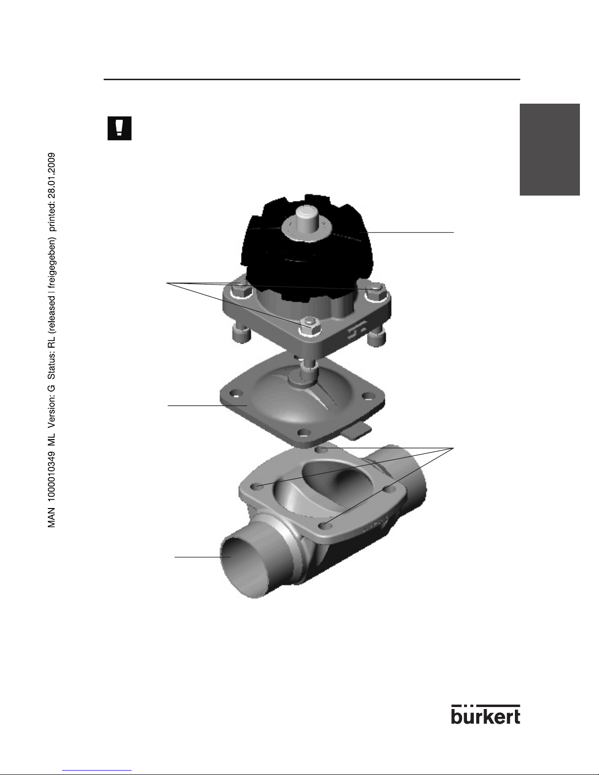
4.2 DISMANTLING THE DIAPHRAGM VALVE
Before dismantling or opening the valve, turn-off the medium and
depressurize the pipes.
Diaphragm
Valve body
Fixing
screws
Handwheel
Holes for
the fixing
screws
 Loading...