

Page 1
Operating Instructions
Bedienungsanleitung
Instructions de Service
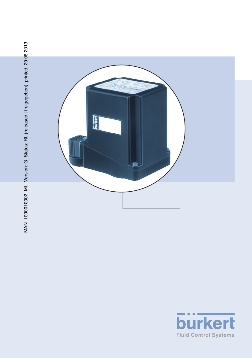
Type 3010
Motorized rotary actuator
Elektromotorischer Drehantrieb
Positionneur électrique
Page 2
We reserve the right to make technical changes without notice.
Technische Änderungen vorbehalten.
Sous resérve de modification techniques.
© 2005 Bürkert Werke GmbH & Co. KG
Operating Instructions 0507/05_EU-ML_00893219
Page 3

Electromagnetic Rotary Actuator Type 3010
GENERAL NOTES ............................................................................................................................................ 2
Symbols .........................................................................................................................................2
Safety notes ..................................................................................................................................2
Application Guidelines .................................................................................................................2
Scope of delivery .........................................................................................................................3
Warranty conditions ....................................................................................................................3
Approval ..........................................................................................................................................3
SYSTEM DESCRIPTION ............................................................................................................................... 4
Application area ............................................................................................................................4
Design .............................................................................................................................................4
Installation ....................................................................................................................................... 4
TECHNICAL DATA ............................................................................................................................................. 5
Dimensions ..................................................................................................................................... 5
General data ..................................................................................................................................5
Mechanical data ............................................................................................................................6
Electrical data ................................................................................................................................6
Electrical connections ..................................................................................................................7
Circuit diagram Type 3010 .........................................................................................................7
englisch
PUTTING INTO OPERATION ....................................................................................................................... 9
OPERATION AND FUNCTION .................................................................................................................... 9
MAINTENANCE .................................................................................................................................................. 9
Safety notes ...................................................................................................................................9
Service .............................................................................................................................................9
Service intervals ......................................................................................................................... 10
Correction of faults ....................................................................................................................10
TRANSPORT AND STORAGE ...................................................................................................................10
DISPOSAL ..........................................................................................................................................................10
3010 - 1
Page 4

GENERAL NOTES
Symbols
The following symbols are used in these operating instructions:
Marks a work step that you must carry out.
ATTENTION!
marks notes on whose non-observance your health or the functioning of the device will be endangered.
englisch
NOTE
Safety notes
Please observe the notes in these operating instructions together with the conditions
of use and permitted data that are specified in the data sheet, in order that the devices will function perfectly and remain operable for a long time:
• Keep to standard engineering rules in planning the use of and operating the
device!
• Take suitable precautions to prevent unintended operation or damage by unauthorized action!
• Interference with the device is only allowed by specialist personnel using suitable
tools!
• Observe the current regulations on accident prevention and safety for electrical
devices during operation, maintenance and repair of the device!
• Before interfering with the system, always switch off the voltage!
• Only use the device in its original configuration
• Ensure the electrical earthing (PE) of the adapters and fitting through the piping
installation!
• On non-observance of this note and unauthorized interference with the device, we
will refuse all liability and the guarantee on device and accessories will become
void!
Application Guidelines
The motorised rotary actuator can be used as ON / OFF or as a control drive.
marks important additional information, tips and
recommendations.
2 - 3010
Page 5
Warranty conditions
This document contains no warranty statements. In this connection we refer to our
general sales and business conditions. A prerequisite for validity of the warranty is use
of the device als intended with observance of the specified conditions of use.
ATTENTION!
The warranty only covers the freedom of the motorised rotary actuator from faults. No liability will be accepted for consequential
damage of any kind that may arise from failure or malfunctioning of
the device.
Scope of delivery
Immediately after receipt of a shipment, make sure that the contents are undamaged
and match the scope of delivery stated on the packing slip.
In case of discrepancy, please contact our Customer centre immediately:
Bürkert Steuer- und Regelungstechnik
Tel. : 07940-10111 Fax: 07940-10448
or your Bürkert Sales Centre.
Kundencenter
Chr.-Bürkert-Str. 13-17
D-76453 Ingelfingen
E-mail: info@de.buerkert.com
Approval
Devices that carry the e1 marking have been approved by the Federal Office for
Motorised Transport under the type approval number
e1*72/245*95/54*3187*00
and will be brought into circulation with the indicated approval designation.
1
e
englisch
023187
You can obtain an excerpt form the type approval from the address below
Bürkert Werke GmbH & Co KG
Zulassungsbeauftragter
Chrisitan-Bürkert-Str. 13 - 17
74653 Ingelfingen
3010 - 3
Page 6
SYSTEM DESCRIPTION
Application area
The motorised rotary actuator can be used as ON / OFF or as a control drive.
Design
The electrical rotary actuator can be selected to consist of a maintenance-free a.c.
motor or a d.c. motor, flanged to a gearbox in each case, with lifetime lubrication, or a
stepper motor.
englisch
The material and design guarantee complete freedom from maintenance, even in
aggressive atmospheres, and a low heat loading of the system.
The control input and the power supply are galvanically separated.
Installation
The installation position is freely selectable, preferably with the drive axis vertical.
Mounting:
- Mount the drive on a standard ISO 5211/FO5 flange (male square) or Bürkert
flange.
- Secure the drive with M6 screws or Ejot PT-screw KA 40 WN 1441 (Bürkert
flange pattern).
ATTENTION!
4 - 3010
The drive must not run against or be blocked by an external
stop.
Page 7
TECHNICAL DATA
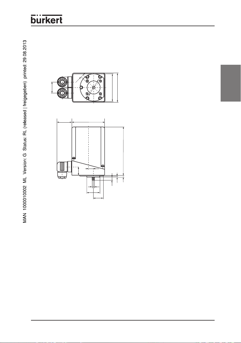
Dimensions
Type 3010 (male square)
Flange pattern according to ISO 5211
30.5
39 89
M6
8 deep
22.5
Ø 35
50
14.5
Ø
80
74
132
3
5.5
8.5
6
27
General data
Ambient temperature -20 ... +60 °C
Weight appr. 0.8 kg
Duty cycle AC: Intermittent operation 70 % ED
DC: Continuous operation 100 % ED
Protection class IP 65
Approval Type approval form Federal Office for Motorised
e1*72/245*95/54*3187*00
englisch
3010 - 5
Page 8
Mechanical data
Casing material Polycarbonate
Rotation angle 90 °C, 180 °C
Shaft end Male square
Output torque AC drive: 5 Nm
DC drive: 6 Nm
englisch
Installation position Any, preferably with drive axis vertical
Electrical data
Operating voltage 220 - 230 V / 50 Hz
12, 24 V DC
Voltage tolerance ± 10 %
Power consumption AC: 10 VA
DC: 10 W
Rotation time for 90% AC drive: 15 s
DC drive: 7.5 s
Electrical connection Appliance socket for cable diameter 6-7 mm
Control Definition of direction of rotation with limit switch
shutdown
Standard signal 4 - 20 mA or 0 to 10 V
Limit switch Single-pole changeover, max. 250 V / 10 A
Standard signal input 4 to 20 mA R
0 to 10 V R
Accuracy with
standard signal control Linearity deviation < ±1.5 %
Hysteresis < ±1.5 %
Factory delivery with
standard signal control "CLOSED" position
(min. Signal = "CLOSED" position)
< 50 Ω
input
> 10 kΩ
input
6 - 3010
Page 9
Electrical connections
S2
right
(OPEN)
left
(OPEN)
left
(CLOSED)
right
(OPEN)
S1
L1
N
PE
1
2
3
1
2
3
S2
right
(OPEN)
left
(CLOSED)
left
(CLOSED)
right
(OPEN)
S1
+
-
PE
1
2
3
1
2
3
M
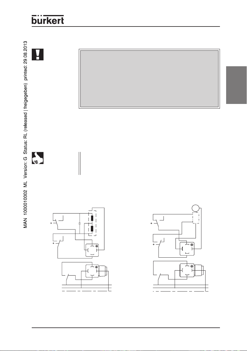
ATTENTION!
The operating voltage and frequency of the electrical supply must
be the same as quoted on the rating plate of the drive.
The voltages and currants must not lie outside the permitted operating range.
For models with rated voltages of 220 V and 110 V, the regulations
for heavy current must be complied with.
Ensure the electrical earthing (PE) of the adapters and fitting through the piping installation.
The switching diagram for the connection of the rotary actuator is located inthe cover of the
drive. The electrical fusing is carried out on the network side. When using a stepper motor,
(Ident. = S), a pulsed control is required. The cable head insert can be rotated by 3 x 90°,
tightening torque 1 Nm.
NOTE
For rotary actuators with a.c. motors, every rotary drive must be
driven via its own switch or is own relay. If several drives are connected in parallel via a common control switch or relay contact, fault
currents may occur that could lead to the destruction of the drive.
Circuit diagram for Type 3010
Standard model AC Standard model DC
englisch
3010 - 7
Page 10
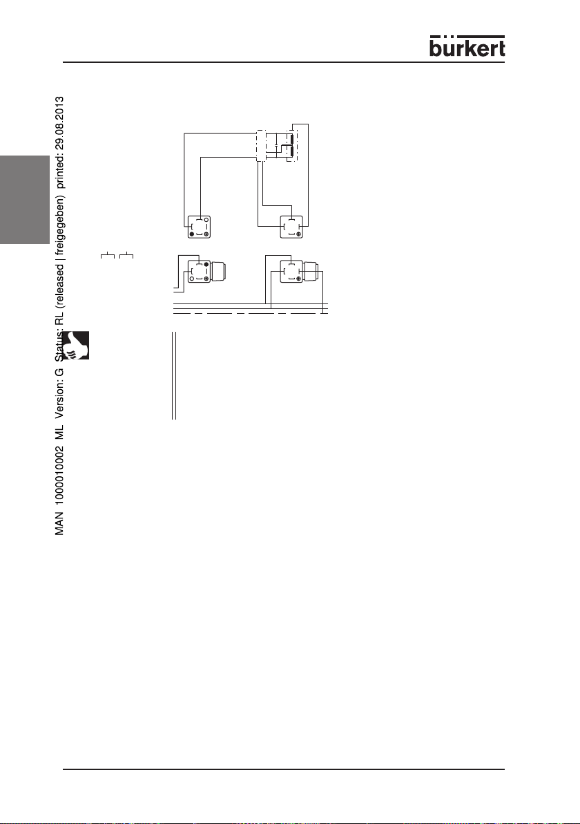
Standard signal input
englisch
0 - 10 V
0 - 20 mA
4 - 20 mA
NOTE
left
right
1
3
2
1
3
2
+
-
L1
N
PE
1
3
2
1
3
2
DIP switches for setting the standard signal input are located on the
circuit board.
S9 to S12 in Position 1: 10 V / 20 mA = OPEN
S9 to S12 in Position 2: 10 V / 20 mA = CLOSED
S13 and S14 in Position 1: 0 ... 10 V input
S13 and S14 in Position 2: 0/4 ... 20 mA input
8 - 3010
Page 11
PUTTING INTO OPERATION
Safety notes
Before putting the motorised rotary actuator into operation, please ensure that:
• the electrical power supply corresponds to the voltage quoted on the rating plate,
• the electrical connections have been carried out as described in the TECHNICAL
DATA chapter,
• the motorised rotary actuator will only be used in its original configuration, and
that it must not be dismantled.
OPERATION AND FUNCTION
Safety notes
During operation and while running, please ensure:
• compliance with the general technical rules!
• the valid accident prevention and safety regulations for electrical device.
MAINTENANCE
Safety notes
During maintenance and service work, ensure that:
• work on the devices may only be carried out by persons who have been authorised
and have received the corresponding training.
englisch
• the devices must be switched free of electrical voltage before the start of the maintenance work.
• the national regulations valid in the country of use are complied with.
Service
Check the following within the context of the service work:
• that the connections are firmly seated,
• the plastic body for cracks and other visible damage,
• the maintenance of the permitted temperatures (see the TECHNICAL DATA
chapter),
• the proper functioning of the device.
3010 - 9
Page 12

Service intervals
Regularly check that the motorised rotary actuator is in its correct condition with
regard to the mounting, installation and operation.
Take the following factors into consideration when determining the inspection intervals:
• Operating conditions (loading level, incorrect operation),
• the manufacturer's data in the technical documentation (mechanical and electri-
englisch
cal service life),
• major changes in the system.
Correction of faults
If you detect faults that that impair the functionality of the motorised rotary actuator,
they must be corrected immediately:
• Place the device out of operation, and switch it free of voltage!
• Correct the fault.
• Put the device back into operation.
TRANSPORT AND STOCKAGE
Transport and storage are only permitted in the original packaging.
DISPOSAL
NOTE
10 - 3010
Observe the national regulations for the disposal of waste in the
respective country of use.
Page 13

Elektromagnetischer Drehantrieb Typ 3010
ALLGEMEINE HINWEISE ...........................................................................................................................12
Darstellungsmittel ..................................................................................................................... 12
Sicherheitshinweise ................................................................................................................. 12
Bestimmungsgemäßer Gebrauch .......................................................................................... 12
Garantiebestimmungen ........................................................................................................... 13
Lieferumfang .............................................................................................................................. 13
Zulassungen ................................................................................................................................ 13
SYSTEMBESCHREIBUNG ........................................................................................................................14
Einsatz .......................................................................................................................................... 14
Aufbau .......................................................................................................................................... 14
Einbau ........................................................................................................................................... 14
TECHNISCHE DATEN ...................................................................................................................................15
Abmessungen ............................................................................................................................. 15
Allgemeine Daten ....................................................................................................................... 15
Mechanische Daten ...................................................................................................................16
Elektrische Daten ....................................................................................................................... 16
Elektrische Anschlüsse ............................................................................................................. 17
Schaltbilder Typ 3010 .............................................................................................................. 17
deutsch
INBETRIEBNAHME ........................................................................................................................................19
BEDIENUNG UND FUNKTION .................................................................................................................19
INSTANDHALTUNG ........................................................................................................................................19
Sicherheitshinweise .................................................................................................................. 19
Wartung ....................................................................................................................................... 19
Wartungsintervalle ..................................................................................................................... 20
Beseititgung von Fehlern .........................................................................................................20
TRANSPORT UND LAGERUNG ...............................................................................................................20
ENTSORGUNG .................................................................................................................................................20
3010 - 11
Page 14

ALLGEMEINE HINWEISE
Darstellungsmittel
In dieser Betriebsanleitung werden folgende Darstellungsmittel verwendet:
markiert einen Arbeitsschritt, den Sie ausführen müssen.
ACHTUNG!
kennzeichnet Hinweise, bei deren Nichtbeachtung Ihre Gesundheit
oder die Funktionsfähigkeit des Gerätes gefährdet ist.
HINWEIS
kennzeichnet wichtige Zusatzinformationen,
Tipps und Empfehlungen.
Sicherheitshinweise
Bitte beachten Sie die Hinweise dieser Betriebsanleitung sowie die Einsatzbedin-
deutsch
gungen und zulässigen Daten, die im Datenblatt spezifiziert sind, damit das Gerät
einwandfrei funktioniert und lange einsatzfähig bleibt:
• Halten Sie sich bei der Einsatzplanung und dem Betrieb des Gerätes an die allgemeinen Regeln der Technik!
• Treffen Sie geeignete Maßnahmen, um unbeabsichtigtes Betätigen oder unzulässige Beeinträchtigung auszuschließen!
• Installation und Wartungsarbeiten dürfen nur durch Fachpersonal und mit geeignetem Werkzeug erfolgen!
• Beachten Sie die geltenden Unfallverhütungs- und Sicherheitsbestimmungen für
elektrische Geräte während des Betriebs und der Wartung des Gerätes!
• Schalten Sie vor Eingriffen in das System in jedem Fall die Spannung ab!
• Verwenden Sie das Gerät nur in seiner Originalkonfiguration!
• Gewährleisten Sie die elektrische Erdung (PE) der Adaptionsteile und Armatur
über die Leitungsinstallation!
• Bei Nichtbeachtung dieser Hinweise und unzulässigen Eingriffen in das Gerät
entfällt jegliche Haftung unsererseits, ebenso erlischt die Garantie auf Geräte und
Zubehörteile!
Bestimmungsgemäßer Gebrauch
Der elektromotorische Drehantrieb ist als AUF / Zu oder als Regelantrieb einsetzbar.
12 - 3010
Page 15

Garantiebestimmungen
Diese Druckschrift enthält keine Garantiezusagen. Wir verweisen hierzu auf unsere
allgemeinen Verkaufs- und Geschäftsbedingungen. Voraussetzung für die Garantie ist
der bestimmungsgemäße Gebrauch des Gerätes unter Beachtung der spezifizierten
Einsatzbedingungen.
ACHTUNG!
Die Gewährleistung erstreckt sich nur auf die Fehlerfreiheit des
elektromotorischen Drehantriebes. Es wird jedoch keine Haftung
übernommen für Folgeschäden jeglicher Art, die durch Ausfall oder
Fehlfunktion des Gerätes entstehen könnten.
Lieferumfang
Überzeugen Sie sich unmittelbar nach Erhalt der Sendung, dass der Inhalt nicht beschädigt ist und mit dem auf dem beigelegten Packzettel angegebenen Lieferumfang
übereinstimmt.
Bei Unstimmigkeiten wenden Sie sich bitte umgehend an unseren Kundenservice:
Bürkert Steuer- und Regelungstechnik
Tel. : 07940-10111 Fax: 07940-10448
oder an Ihr Bürkert-Vertriebs-Center.
Kundencenter
Chr.-Bürkert-Str. 13-17
D-76453 Ingelfingen
E-mail: info@de.buerkert.com
Zulassung
Geräte, die das Typgenehmigungskennzeichen tragen müssen, wurden beim Kraftfahrtbundesamt unter der Typgenehmigungsnummer
e1*72/245*95/54*3187*00
genehmigt und werden mit dem gezeigten Typgenehmigungszeichen in den Verkehr
gebracht.
1
e
deutsch
023187
Einen Auszug der Typgenehmigung erhalten Sie unter der unten stehenden Adresse.
Bürkert Werke GmbH & Co KG
Zulassungsbeauftragter
Chrisitan-Bürkert-Str. 13 - 17
74653 Ingelfingen
3010 - 13
Page 16

SYSTEMBESCHREIBUNG
Einsatz
Der elektromotorische Drehantrieb ist als AUF / ZU oder als Regelantrieb einsetzbar.
Aufbau
Der elektrische Drehantrieb besteht wahlweise aus einem wartungsfreien Wechselstrommotor oder einem Gleichstrommotor, jeweils aufgeflanscht auf ein Getriebe mit
Lebensdauerschmierung, bzw. auf einen Schrittmotor.
Material und Ausführung gewährleisten völlige Wartungsfreiheit auch in aggressiver
Atmosphäre und eine geringe Wärmebelastung des Systems.
Steuereingang und Stromversorgung sind galvanisch getrennt.
Einbau
deutsch
Die Einbaulage ist beliebig, vorzugsweise mit vertikaler Antriebsachse.
Montage:
- Antrieb auf Normflansch ISO 5211/FO5 (Außenvierkant) oder Bürkert-Flansch
aufsetzen
- Antrieb mit Schrauben M6 bzw. Ejot PT-Schraube KA 40 WN 1441 (Bürkert-
Flanschbild) befestigen.
ACHTUNG!
14 - 3010
Der Antrieb darf nicht gegen einen externen Anschlag fahren bzw.
blockiert werden.
Page 17

TECHNISCHE DATEN
Abmessungen
Typ 3010 (Außenvierkant)
Flanschbild nach ISO 5211
30,5
39 89
M6
8 tief
22,5
Ø 35
50
14,5
Ø
80
74
132
3
5,5
8,5
6
27
Allgemeine Daten
Umgebungstemperatur -20 bis +60 °C
Gewicht ca. 0,8 kg
Nennbetriebsart AC: Aussetzbetrieb 70 % ED
DC: Dauerbetrieb 100 % ED
Schutzart IP 65
Zulassung Typgenehmigung beim Kraftfahrtbundesamt
e1*72/245*95/54*3187*00
deutsch
3010 - 15
Page 18

Mechanische Daten
Gehäusewerkstoff Polycarbonat
Stellwinkel 90 °C, 180 °C
Wellenende Außenvierkant
Antriebsdrehmoment AC-Antrieb: 5 Nm
DC-Antrieb: 6 Nm
Einbaulage beliebig, vorzugsweise mit vertikaler
Antriebsachse
Elektrische Daten
deutsch
Betriebsspannung 220 - 230 V / 50 Hz
12, 24 V DC
Spannungstoleranz ± 10 %
Elektrische
Leistungsaufnahme AC: 10 VA
DC: 10 W
Stellzeit für 90% AC-Antrieb: 15 s
DC-Antrieb: 7,5 s
Elektrischer Anschluss Gerätesteckdosen für Kabeldurchmesser 6-7 mm
Ansteuerung Vorgabe der Drehrichtung mit Endlagen-
abschaltung
Normsignal 4 - 20 mA oder 0 bis 10 V
Endschalter einpoliger Umschalter, max. 250 V / 10 A
Normsignaleingang 4 bis 20 mA R
0 bis 10 V R
Genauigkeit bei Normsignalansteuerung Linearitätsabweichung < ±1,5 %
Hysterese < ±1,5 %
Werksauslieferung bei
Normsignalansteuerung Stellung "ZU"
(min. Signal = Stellung "ZU")
eingang
eingang
< 50 Ω
> 10 kΩ
16 - 3010
Page 19

Elektrische Anschlüsse
S2
rechts
(AUF)
links
(AUF)
links
(ZU)
rechts
(AUF)
S1
L1
N
PE
1
2
3
1
2
3
ACHTUNG!
Die Betriebsspannung und Frequenz der Versorgung müssen mit
den Typschildangaben des Antriebs übereinstimmen.
Die Spannungen und Ströme dürfen nicht außerhalb des zulässigen
Betriebsbereichs liegen.
Bei Geräteausführung mit Nennspannung von 220 V und 110 V
sind die Vorschriften für Starkstrom zu beachten.
Gewährleisten Sie die Elektrische Erdung (PE) der Adaptionsteile
und Armatur über die Leitungsinstallation.
Der Schaltplan zum Anschluss des Drehantriebes befindet sich im Deckel des Antriebes.
Die elektrische Absicherung erfolgt netzseitig. Beim Einsatz eines Schrittmotors (Kennz. =
S) ist eine Taktsteuerung erforderlich. Der Einsatz des Kabelkopfes ist um 3 x 90° drehbar,
Anzugsmoment 1 Nm.
HINWEIS
Bei Drehantrieben mit Wechselstrommotor ist jeder Drehantrieb
über einen eigenen Schalter oder ein eigenes Relais anzusteuern.
Bei direktem Parallelschalten mehrerer Antriebe über einen gemeinsamen Ansteuerschalter oder Relaiskontakt entstehen Fehlströme,
die zur Zerstörung des Antriebes führen können.
Schaltbilder Typ 3010
Standardausführung AC Standardausführung DC
M
rechts
S2
(AUF)
deutsch
links
S1
rechts
(AUF)
(ZU)
links
(ZU)
+
-
PE
3
3
1
2
1
2
3010 - 17
Page 20

Normsignaleingang
0 - 10 V
0 - 20 mA
4 - 20 mA
deutsch
HINWEIS
links
rechts
1
3
2
1
3
2
+
-
L1
N
PE
1
3
2
1
3
2
Auf der Platine befinden sich DIP-Schalter zur Einstellung des
Normsignaleinganges.
S9 bis S12 in Stellung 1: 10 V / 20 mA = AUF
S9 bis S12 in Stellung 2: 10 V / 20 mA = ZU
S13 und S14 in Stellung 1: 0 ... 10 V Eingang
S13 und S14 in Stellung 2: 0/4 ... 20 mA Eingang
18 - 3010
Page 21

INBETRIEBNAHME
Sicherheitshinweise
Bitte beachten Sie vor der Inbetriebnahme des elektromotorischen Drehantriebs, dass
• die Stromversorgungsspannung der auf dem Typenschild angegebenen Span nung entsprechen muss,
• die elektrischen Anschlüsse wie im Kapitel Technische Daten beschrieben aus geführt werden müssen,
• der elektromotorische Drehantrieb nur in seiner Originalkonfiguration verwendet
und nicht demontiert werden darf.
BEDIENUNG UND FUNKTION
Sicherheitshinweise
Bitte beachten Sie bei der Bedienung und im Betrieb
• die Einhaltung der allgemeinen Regeln der Technik!
• die geltenden Unfallverhütungs- und Sicherheitsbestimmungen für elektrische
Geräte.
INSTANDHALTUNG
Sicherheitshinweise
Bitte beachten Sie bei der Instandhaltung und Wartung, dass
• die Arbeiten an den Komponenten nur von dazu befugtem und entsprechend geschultem Personal durchgeführt werden dürfen.
deutsch
• die Geräte vor Beginn der Wartungsarbeiten spannungsfrei zu schalten sind.
• die geltenden nationalen Bestimmungen im Einsatzland eingehalten werden müssen.
Wartung
Überprüfen Sie im Rahmen der Wartung:
• die Anschlüsse auf festen Sitz,
• das Kunststoffgehäuse auf Rissbildung und andere sichtbare Schäden,
• die Einhaltung der zulässigen Temperaturen (siehe Kapitel Technische Daten),
• die bestimmungsgemäße Funktion.
3010 - 19
Page 22

Wartungsintervalle
Prüfen Sie den elektromotorischen Drehantrieb auf seinen ordnungsgemäße Zustand
hinsichtlich der Montage, der Installation und des Betriebes regelmäßig.
Berücksichtigen Sie die folgenden Faktoren bei der Festlegung der Prüfintervalle:
• Betriebsbedingungen (Auslastungsgrad, Fehlbedienung),
• Herstellerangaben in der technischen Dokumentation (mechanische und elektri
sche Lebensdauer) ,
• größere Veränderungen im System.
Beseitigung von Fehlern
Haben Sie Fehler festgestellt, die sich auf die Funktionsfähigkeit des elektromotori-
deutsch
schen Drehantriebs auswirken, müssen diese sofort beseitigt werden:
• Setzen Sie das Gerät außer Betrieb, schalten Sie es spannungsfrei!
• Beseitigen Sie den Fehler.
• Nehmen Sie das Gerät wieder in Betrieb.
TRANSPORT UND LAGERUNG
Transport und Lagerung sind nur in Originalverpackung gestattet.
ENTSORGUNG
HINWEIS
20 - 3010
Beachten Sie die nationalen Vorschriften zur Abfallentsorgung im
jeweiligen Einsatzland.
Page 23

Entraînement rotatif électromagnétique type 3010
INDICATIONS GENERALES .....................................................................................................................22
Symboles utilisés ...................................................................................................................... 22
Consignes de sécurité ............................................................................................................22
Utilisation conforme aux instructions .....................................................................................22
Clauses de garantie ................................................................................................................. 23
Fourniture .................................................................................................................................... 23
Homologation ............................................................................................................................. 23
DESCRIPTION DU SYSTEME ..................................................................................................................24
Mise en oeuvre ........................................................................................................................... 24
Construction ............................................................................................................................... 24
Montage ....................................................................................................................................... 24
CARACTERISTIQUES TECHNIQUES ...................................................................................................25
Dimensions .................................................................................................................................. 25
Caractéristiques générales ...................................................................................................... 25
Caractéristiques mécaniques ................................................................................................. 26
Caractéristiques électriques ................................................................................................... 26
Branchements électriques ....................................................................................................... 27
Schémas de connexions type 3010 ...................................................................................... 27
français
MISE EN SERVICE .........................................................................................................................................29
COMMANDE ET FONCTIONNEMENT ..................................................................................................29
MAINTENANCE ................................................................................................................................................29
Consignes de sécurité .............................................................................................................. 29
Entretien ....................................................................................................................................... 29
Intervalle d'entretien .................................................................................................................. 30
Elimination des défauts ............................................................................................................. 30
TRANSPORT ET STOCKAGE ....................................................................................................................30
MISE AU REBUT .............................................................................................................................................30
3010 - 21
Page 24

INDICATIONS GENERALES
Symbols utilisés
Les symboles utilisés dans cette notice d'instructions sont les suivants:
désigne une opération à exécuter.
ATTENTION!
désigne une mise en garde dont l'inobservation pourrait mettre en
danger votre santé ou l'intégrité de l'appareil.
REMARQUE
désigne des informations supplémentaires, conseils et recommandations importantes.
Consignes de sécurité
Veuillez tenir compte des directives figurant dans ces instructions de service de
même que des conditions d'utilisation et des données autorisées spécifiées dans
la fiche technique pour que l'appareil fonctionne parfaitement et reste longtemps
opérationnel:
• S'en tenir lors de la mise en oeuvre prévue et du service de l'appareil aux règles
techniques générales reconnues!
• Prendre les mesures qui s'imposement pour éviter un actionnement par inadver-
français
tance de l'appareil ou une mise en cause inadmissible de son fonctionnement!
• L'installation et les interventions nécessitées par la maintenance ne doivent être
effectuées que par un personnel qualifié équipé des outils adéquats!
• Respecter les dispositions en vigueur de prévention des accidents et de sécurité
pour appareils électriques pendant le service, la maintenance de l'appareil!
• Toujours couper la tension d'alimentation avant toute intervention dans le systeme!
• N'utiliser l'appareil que dans sa configuration originale!
• Assurez-vous que les pièces d'adaptation et de robinetterie sont reliées à la terre
(PE) via la tuyauterie!
• Nous déclinons toute responsabilité en cas d'inobservation de ces recommendations et d'intervention non autorisée à l'intérieur de l'appareil. Il en résulterait par
ailleurs l'extinction de la garantie sur l'appareil et les accessoires!
Utilisation conforme aux instructions
L'entraînement rotatif à moteur électrique peut être utilisé pour les fonctions
OUVRIR / FERMER ou comme mécanisme régulateur.
22 - 3010
Page 25

Clauses de garantie
Ce document ne constitue aucune assentiment de garantie. Nous vous renvoyons à
cet effet à nos conditions générales de vente et commerciales. La condition préalable
au consentement de la garantie est l'utilisation conforme de l'appareil à l'usage auquel
il est destiné, compte tenu de l'observation des conditions d'emploi spécifiées.
ATTENTION!
La prestation de garantie s'étend exclusivement à l'absence de
défauts sur l'entraînement rotatif à moteur électrique. Nous déclinons, par contre, toute reponsabilité pour des dégâts consécutifs
de toute nature susceptibles de survenir par suite de défaillance ou
défaut de fonctionnement de l'appareil.
Fourniture
S'assurer immédiatement après réception de la fourniture si le contenu est conforme
à ce qui a été indiqué.
En cas de litiges, veuillez vous adresser sans délai à notre centre client:
Bürkert Steuer- und Regelungstechnik
Tel. : 07940-10111 Fax: 07940-10448
ou à votre centre de distribution Bürkert.
Kundencenter
Chr.-Bürkert-Str. 13-17
D-76453 Ingelfingen
E-mail: info@de.buerkert.com
Homologation
Les appareils portant la marque e1 ont été homologués au Service fédéral de la circulation automobile (Kraftfahrtbundesamt) sous le numéro
e1*72/245*95/54*3187*00
et seront mis en circulation avec d'la marque d'homologation indiquée.
1
e
français
023187
Vous recevrez un extrait de l'homologation à l'adresse ci-dessous:
Bürkert Werke GmbH & Co KG
Zulassungsbeauftragter
Chrisitan-Bürkert-Str. 13 - 17
74653 Ingelfingen
3010 - 23
Page 26

DESCRIPTION DU SYSTEME
Mise en oeuvre
L'entraînement rotatif à moteur électrique peut être utilisé pour les fonctions
OUVRIR / FERMER ou comme mécanisme régulateur.
Construction
L'entraînement rotatif électrique comprend au choix un moteur à courant alternatif
ou un moteur à courant continu ne nécessitant pas d'entretien, qui est fixé respectivement sur un engrenage réducteur doté d'une lubrification à vie ou sur un moteur
pas-à-pas.
Le matériel et le modèle garantissent un fonctionnement ne nécessitant aucun entretien de l'entraînement, même en atmosphère agressive, et sollicitant peu le système au
niveau thermique.
L'entrée de commande et l'alimentation électrique sont séparées électriquement.
Montage
Vous pouvez monter l'entraînement à votre guise, de préférence avec l'axe
d'entraînement à la verticale.
Montage:
- Poser l'entraînement sur une bride standard ISO 5211/FO5 (carré mâle) ou une
français
bride Bürkert.
- Fixer l'entraînement au moyen de vis M6 resp. de vis PT Ejot KA 40 WN 1441
(modèle de bride Bürkert).
ATTENTION!
24 - 3010
L'entraînement ne doit pas venir heurter une butée externe, resp.
être bloqué.
Page 27

CARACTERISTIQUES TECHNIQUES
Dimensions
Type 3010 (carré mâle)
Profile de bride selon ISO 5211
30,5
39 89
M6
8 tief
22,5
Ø 35
50
14,5
Ø
80
74
132
3
5,5
8,5
6
27
Caractéristiques générales
Température ambiante -20 ... +60 °C
Poids env. 0,8 kg
Mode de service nominal AC: service discontinu 70 % ED
DC: service continu 100 % ED
Protection IP 65
Homologation Homologation de type au Bureau fédéral du
trafic automobile
e1*72/245*95/54*3187*00
français
3010 - 25
Page 28

Caractéristiques mécaniques
Matériau du boîtier polycarbonate
Angle de positionnement 90 °C, 180 °C
Extrémité d'arbre carré mâle
Couple d'entraînement entraînement AC: 5 Nm
entraînement DC: 6 Nm
Position de montage à votre guise, de préférence avec axe
d'entraînement à la verticale
Caractéristiques électriques
Tension de service 220 - 230 V / 50 Hz
12, 24 V DC
Tolérance de tension ± 10 %
Puissance électrique
absorbée AC: 10 VA
DC: 10 W
français
Temps de positionnement entraînement AC: 15 s
pour 90% entraînement DC: 7,5 s
Branchement électrique
Commande
en fin de course
signal standard 4 - 20 mA ou 0 à 10 V
Interrupteur de fin
de course commutateur monopolaire, max. 250 V / 10 A
Entrée signal standard 4 à 20 mA R
0 à 10 V R
Précision lors de l'activation écart de linéarité < ±1,5 %
du signal standard hystérésis < ±1,5 %
Livraison d'usine avec
activation signal standard position "FERME"
(signal min. = position "FERME")
connecteurs pour diamètre de câble 6-7 mm
valeur par défaut du sens de rotation avec coupure
< 50 Ω
entrée
> 10 kΩ
entrée
26 - 3010
Page 29

Branchements électriques
S2
droite
(OUVRIR)
gauche
(OUVRIR)
gauche
(FERMER)
droite
(OUVRIR)
S1
L1
N
PE
1
2
3
1
2
3
S2
droite
(OUVRIR)
gauche
(FERMER)
gauche
(FERMER)
droite
(OUVRIR)
S1
+
-
PE
1
2
3
1
2
3
M
ATTENTION!
La tension et la fréquence d'exploitation de l'alimentation doivent
correspondre aux indications figurant sur la plaque signalétique de
l'entraînement.
Les courants et tensions ne doivent pas se trouver hors de la plage
d'exploitation autorisée.
Pour le type d'appareil avec tension nominale de 220 V et 110 V, il
faut observer les directives relatives au courant fort.
Assurez-vous que les pièces d'adaptation et de robinetterie sont
relièes électriquement à la terre (PE) via la tuyauterie.
Le schéma de connexions pour le raccordement de l'entraînement rotatif se trouve dans le
couvercle de l'entraînement. La protection par fusible se fait au niveau du réseau. Si vous
utilisez un moteur pas-à-pas (marquage = S), une commande de cycle est indispensable.
L'insert de la tête de câble peut être tourné de 3 x 90°, couple de serrage 1 Nm.
REMARQUE
Pour les entraînements rotatifs avec moteur à courant alternatif,
chaque entraînement doit être commandé au moyen d'un propre
interrupteur ou d'un propre relais. Si vous connectez directement
plusieurs entraînements en parallèle via un interrupteur de commande commun ou un contact de relais, des courants de défaut
susceptibles de détruire l'entraînement se créent.
Schémas de connexions type 3010
Exécution standard AC Exécution standard DC
français
3010 - 27
Page 30

Entrée du signal standard
0 - 10 V
0 - 20 mA
4 - 20 mA
REMARQUE
français
gauche
droite
1
3
2
1
3
2
+
-
L1
N
PE
1
3
2
1
3
2
Sur la platine se trouvent des interrupteurs DIP servant au réglage
de l'entrée du signal standard.
S9 à S12 en position 1: 10 V / 20 mA = OUVERT
S9 à S12 en position 2: 10 V / 20 mA = FERME
S13 et S14 en position 1: entrée 0 ... 10 V
S13 et S14 en position 2: entrée 0/4 ... 20 mA
28 - 3010
Page 31

MISE EN SERVICE
Consignes de sécurité
Avant de mettre en service l'entraînement rotatif à moteur électrique, veuillez prendre
en considération ce qui suit:
• la tension d'alimentation corresponde à celle indiquée,
• les branchements électriques soient réalisés comme décrit au cap.
CARACTERISTIQUES TECHNIQUES,
• l'entraînement rotatif à moteur électrique ne peut être utilisé que dans configurati
on d'origine et ne doit pas être démonté.
COMMANDE ET FONCTIONNEMENT
Consignes de sécurité
Veuillez tenir compte lors de la manipulation et du service
• au respect des règles générales de la technique!
• aux prescriptions en vigueur de prévention des accidents et de sécurité concernant
les appareils électriques.
MAINTENANCE
Consignes de sécurité
Lors du maniement et durant le service, veillez à ce que
• les travaux sur les appareils soient exécutés uniquement par des personnes affectées à cet effet et formées en conséquence.
français
• les appareils soient déconnectés de la tension avant de commencer les travaux
d'entretien.
• les prescriptions nationales en vigueur das le pays d'emploi soient respectées.
Entretien
Contrôler dans le cadre de l'entretien:
• que les raccords soient bien serrés,
• l'absence de fissure et autres dégâts visibles sur le carter en plastique,
• le respect des températures tolérées (voir chap. CARACTERISTIQUES TECHNIQUES),
• le fonctionnement conforme à la destination.
3010 - 29
Page 32

Intervalle d'entretien
Contrôlez régulièrement si l'état de l'entraînement rotatif à moteur électrique est réglementaire en ce qui concerne le montage, l'installation et le fonctionnement.
Tenir compte des facteurs suivants lors de l'établissement des intervalls de contrôle:
• conditions de service (niveau de charge, erreurs de manipulation),
• des indications du constructeur dans la documentation technique (longévité
mécanique et électrique) ,
• modification plus importante du système.
Elimination des défauts
Si vous constatez des défauts pouvant se répercuter sur la capacité de fonctionnement de l'entraînement rotatif à moteur électrique, ceux-ci doivent être éliminés immédiatement:
• Mettre l'appareil hors service et hors tension!
• Remédier au défaut.
• Remettre l'appareil en service.
français
TRANSPORT ET STOCKAGE
Le transport et le stockage ne sont autorisés que dans l'emballage original.
MISE AU REBUT
REMARQUE
30 - 3010
Tenir compte des prescriptions nationales du pays d'emploi pour la
mise au rebut.
Page 33

Bürkert Company Locations
Contact addresses / Kontaktadressen
Germany / Deutschland / Allemange
Bürkert Fluid Control System
Sales Centre
Chr.-Bürkert-Str. 13-17
D-74653 Ingelfingen
Tel. + 49 (0) 7940 - 10 91 111
Fax + 49 (0) 7940 - 10 91 448
E-mail: info@de.buerkert.com
International
Contact addresses can be found on the internet at:
Die Kontaktadressen finden Sie im Internet unter:
Les adresses se trouvent sur internet sous :
www.burkert.com
Page 34

The smart choice
of Fluid Control Systems
www.buerkert.com
 Loading...