

Page 1
Type 3005
Electromotive rotary actuator
Elektromotorischer Drehantrieb
Actionneur électrique
Operating Instructions
Bedienungsanleitung
Instructions de Service
Page 2

We reserve the right to make technical changes without notice.
Technische Änderungen vorbehalten.
Sous resérve de modification techniques.
© 2008 - 2013 Bürkert Werke GmbH
Operating Instructions 1303/03_EU-ML_00805753 / Original DE
Page 3
Type 3005
Electromotive rotary actuator Type 3005
Contents
1. OPERATING INSTRUCTIONS ........................................................................................................................................................5
1.1. Symbols ......................................................................................................................................................................................5
2. CORRECT USE ......................................................................................................................................................................................6
2.1. Restrictions ...............................................................................................................................................................................6
3. GENERAL SAFETY INSTRUCTIONS ..........................................................................................................................................7
4. GENERAL INFORMATION ................................................................................................................................................................8
4.1. Contact address .....................................................................................................................................................................8
4.2. Warranty ......................................................................................................................................................................................8
4.3. Information on the Internet ...............................................................................................................................................8
5. SYSTEM DESCRIPTION ...................................................................................................................................................................9
5.1. Designated Application Area ...........................................................................................................................................9
5.2. General Description ..............................................................................................................................................................9
5.3. Exploded views ....................................................................................................................................................................10
5.4. Options .....................................................................................................................................................................................13
6. TECHNICAL DATA .............................................................................................................................................................................14
6.1. Conformity ..............................................................................................................................................................................14
6.2. Standards ................................................................................................................................................................................14
6.3. Approval ...................................................................................................................................................................................14
6.4. Operating Conditions ........................................................................................................................................................14
6.5. Identification ..........................................................................................................................................................................14
6.6. General Technical Data ....................................................................................................................................................15
7. INSTALLATION ...................................................................................................................................................................................20
7.1. Safety instructions .............................................................................................................................................................20
7.2. Installing the rotary actuator .........................................................................................................................................20
8. INSTALLATION ...................................................................................................................................................................................24
English
3
Page 4

Type 3005
8.1. Safety instructions .............................................................................................................................................................24
8.2. Electrical installation .........................................................................................................................................................24
8.3. Control card ...........................................................................................................................................................................29
9. OPTION: ROTARY ACTUATORS WITH EMERGENCY CURRENT MODEL ...........................................................33
9.1. Description .............................................................................................................................................................................33
9.2. Technical Data ......................................................................................................................................................................33
9.3. Electrical connection of safety block .......................................................................................................................34
9.4. Installation of safety block into the actuator drive ...........................................................................................36
10. START-UP .............................................................................................................................................................................................37
10.1. Safety instructions .............................................................................................................................................................37
10.2. Procedure ................................................................................................................................................................................37
11. OPERATION AND FUNCTION ....................................................................................................................................................38
11.1. Safety instructions .............................................................................................................................................................38
11.2. Manual operation ................................................................................................................................................................38
12. MAINTENANCE, TROUBLESHOOTING .................................................................................................................................39
12.1. Safety instructions .............................................................................................................................................................39
12.2. Maintenance Work ..............................................................................................................................................................39
12.3. Malfunctions ..........................................................................................................................................................................39
13. ACCESSORIES ..................................................................................................................................................................................41
14. PACKAGING AND TRANSPORT ...............................................................................................................................................42
15. STORAGE ..............................................................................................................................................................................................42
16. DISPOSAL ............................................................................................................................................................................................42
4
English
Page 5
Type 3005
Operating Instructions
1. OPERATING INSTRUCTIONS
The operating instructions describe the entire life cycle of the device. Keep these instructions in a location which is
easily accessible to every user and make these instructions available to every new owner of the device.
WARNING!
The operating instructions contain important safety information!
Failure to observe these instructions may result in hazardous situations.
• The operating instructions must be read and understood.
1.1. Symbols
DANGER!
Warns of an immediate danger!
• Failure to observe the warning may result in a fatal or serious injury.
WARNING!
Warns of a potentially dangerous situation!
• Failure to observe the warning may result in serious injuries or death.
CAUTION!
Warns of a possible danger!
• Failure to observe the warning may result in moderately serious or minor injuries.
NOTE!
Warns of damage to property!
• Failure to observe the warning may result in damage to the device or the equipment.
Designates additional significant information, tips and recommendations.
Refers to information in these operating instructions or in other documentation.
→ designates a procedure which you must carry out.
English
5
Page 6
Type 3005
Correct Use
2. CORRECT USE
WARNING!
Incorrect use of the electromotive rotary actuator Type 3005 can be dangerous to people, nearby equipment
and the environment.
• The rotary actuator can be used indoors, e.g. to actuate fittings, especially ball valves or shut-off flaps.
• During use observe the permitted data, the operating conditions and conditions of use specified in the contract documents and operating instructions, as described in chapter “5. System Description”.
• The device may be used only in conjunction with third-party devices and components recommended and
authorized by Bürkert (e.g. ATEX-approved components).
• Correct transportation, correct storage and installation and careful use and maintenance are essential for reliable and problem-free operation.
• Use the device only as intended.
2.1. Restrictions
If exporting the system/device, observe any existing restrictions.
The electromotive rotary actuator Type 3005 was developed with due consideration given to the accepted
safety rules and is state-of-the-art. However, dangers can still arise.
Operate the device only when it is in perfect condition and in accordance with the operating instructions.
6
English
Page 7
Type 3005
General Safety Instructions
3. GENERAL SAFETY INSTRUCTIONS
These safety instructions do not make allowance for any:
• Contingencies and events which may arise during the installation, operation and maintenance of the devices.
• Local safety regulations; the operator is responsible for observing these regulations, also with reference to the
installation personnel.
DANGER!
Risk of electric shock!
There is a serious risk of injury when reaching into the device.
• Before reaching into the device, always switch off the power supply and safeguard to prevent re-activation!
• Connect several electromotive rotary actuators always with phase separation via a switch.
• Protect the device with a mains-operated fuse.
• Observe applicable accident prevention and safety regulations for electrical equipment!
Danger of explosion!
For specific device designs there is a risk of explosion if the device is opened in the explosion-protected area.
• Follow the safety instructions on the type label!
Danger of explosion caused by electrostatic charge!
If there is a sudden discharge from electrostatically charged devices or persons, there is a danger of explosion in
the EX area.
• Take appropriate measures to prevent electrostatic charges in the EX area.
• Clean the device surface by wiping it gently with a damp cloth.
General hazardous situations.
To prevent injury, ensure:
• That the system cannot be activated unintentionally.
• Type 3005 must not be used in areas where there is a risk of explosion (in this case please use type 3004).
• Do not put any loads on the body (e.g. by placing objects on it or standing on it).
• Do not make any external modifications to the device bodys. Do not paint the body parts or screws.
• Do not install the actuator with the cover facing down (head first).
• Installation and repair work may be carried out by authorized technicians only and with the appropriate tools.
• After an interruption in the power supply or pneumatic supply, ensure that the process is restarted in a
defined or controlled manner.
• The device may be operated only when in perfect condition and in consideration of the operating instructions.
• The general rules of technology apply to application planning and operation of the device.
English
7
Page 8
4. GENERAL INFORMATION
4.1. Contact address
Germany
Bürkert Fluid Control System
Sales Center
Chr.-Bürkert-Str. 13-17
D-74653 Ingelfingen
Phone: +49 (0)7940 - 10 91 111
Fax: +49 (0)7940 - 10 91 448
E-mail: info@de.buerkert.com
International
Type 3005
General Information
Contact addresses can be found on the final pages of the printed operating instructions.
And also on the internet at:
www.buerkert.com
4.2. Warranty
The warranty is only valid if the electromotive rotary actuator Type 3005 is used as intended in accordance with the
specified application conditions.
4.3. Information on the Internet
The operating instructions and data sheets for Type 3005 can be found on the Internet at:
www.burkert.com
8
English
Page 9
Type 3005
System Description
5. SYSTEM DESCRIPTION
5.1. Designated Application Area
The electromotive rotary actuator Type 3005 (designated below as rotary actuator) was developed to control ball
valves or flap valves with a quarter turn. Optionally the actuator is also available at a rotation angle of 180° and 270°.
5.2. General Description
On account of its modular design the basic device can be expanded with many options.
Options for expanding the basic device can be found in chapter “5.4. Options”.
The rotary actuator is a compact and powerful actuator system which ensures a long service life. The rotary actuator
has been designed for direct or alternating current at varying output and for torques from 25 to 1000 Nm (actuator
with analogue signal 25 - 300 Nm).
The utilized materials guarantee maintenance-free operation and ensure a low thermal load. All standard version rotary
actuators feature manual emergency actuation and two additional limit switches and are tested by the manufacturer.
The limit switches have been set to 0 ... 90° swivel operation.
The electromotive rotary actuator is available as an On/Off or variable speed actuator. It can be combined with the
following components:
• Stainless steel ball valve with two-part body (Type 2651),
• Stainless steel ball valve with three-part body (Type 2654),
• Plastic ball valve (Type 2657),
• Metal flap valve (Type 2671),
• Plastic flap valve (Type 2674).
The actuator direction cannot be reversed in the same operating process. The rotary actuator does not reverse
automatically.
Mechanical operation is also possible via the handwheel on the rotary actuator. In electrical mode the handwheel
is not rotated with the actuator.
English
9
Page 10
Type 3005
System Description
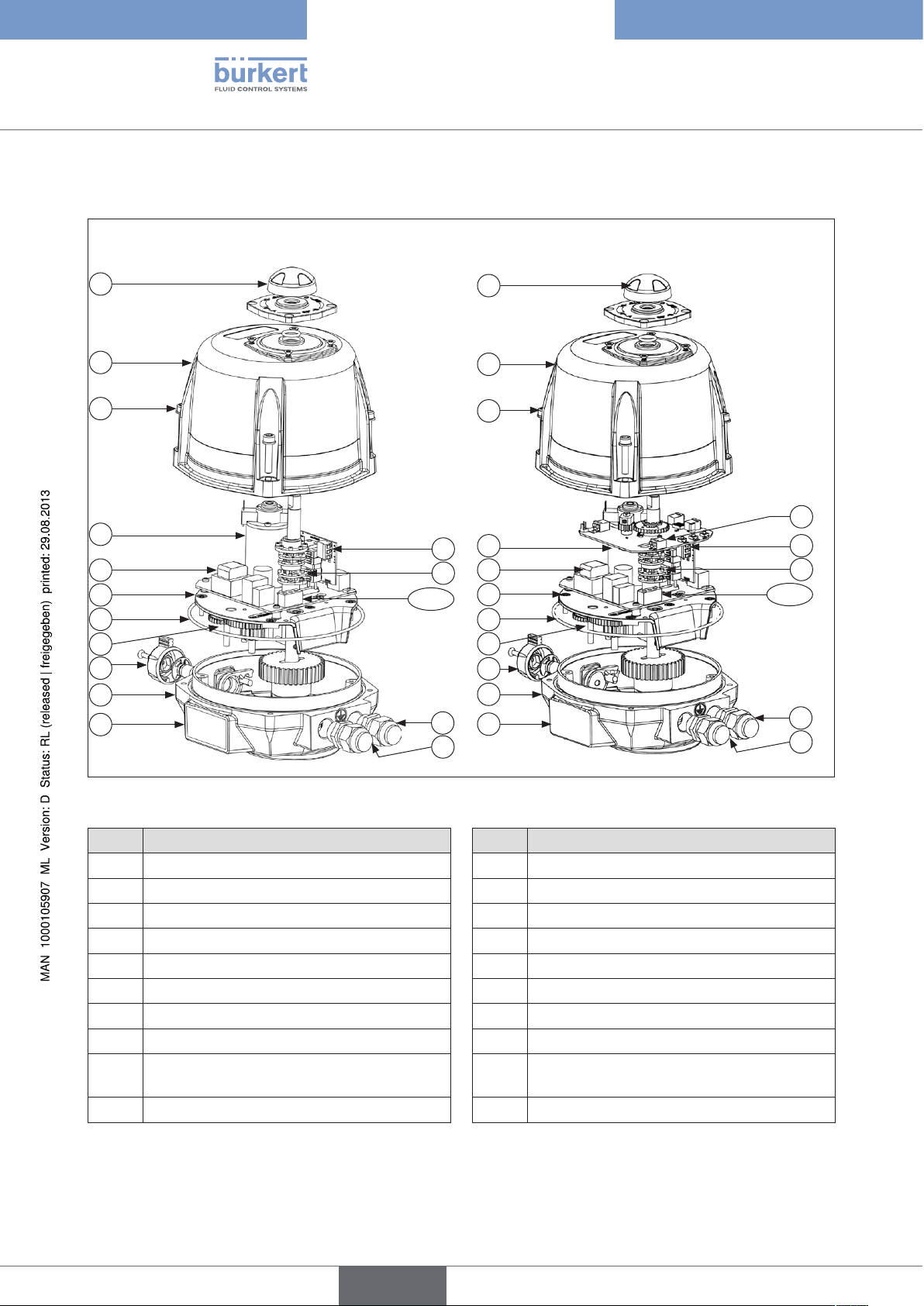
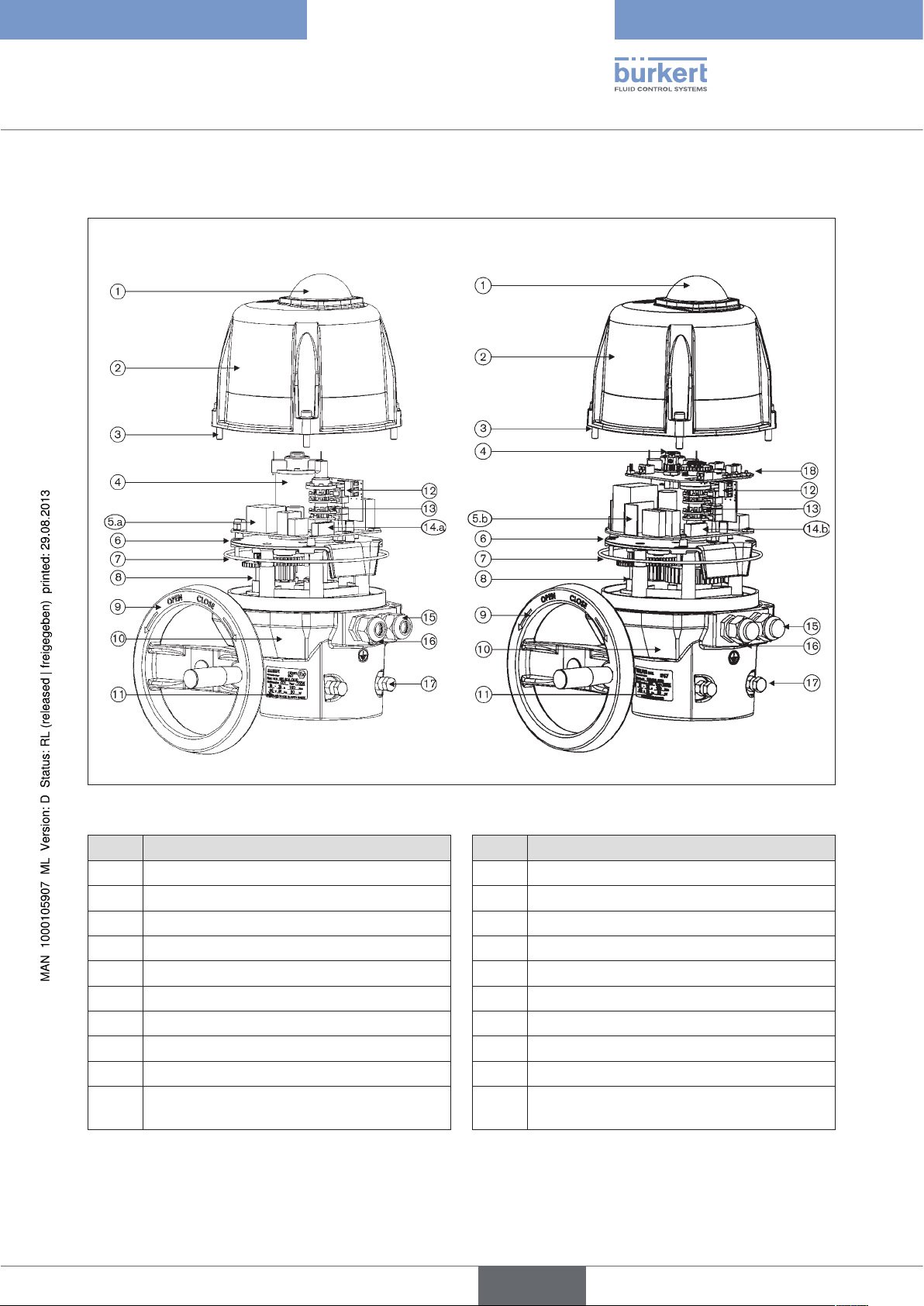
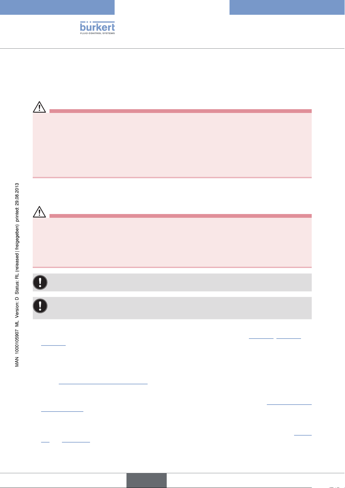
5.3. Exploded views
Motor 25 – 75 Nm Motor 25 – 75 Nm with control card
1
2
3
4
5.a
6
7
8
9
10
11
14.a
12
13
15
16
1
2
3
4
5.b
6
7
8
9
10
11
17
12
13
14.b
15
16
10
Figure 1: Exploded view of motor 25 – 75 Nm
No. Designation No. Designation
1 Position indicator 10 Body
2 Hood 11 Place for type label
3 Stainless steel screws 12 Additional limit switch
4 Motor 13 Cams
5.a* Control and power supply card 14.a* Control and power supply
5.b* Power supply card 14.b* Terminal strip for power supply
6 Gear plate 15 Threaded connection ISO M20
7 O-ring 16 Screw for earth
8 Gears 17 Control card (for variable speed actuator
only)
9 Push-button
English
Page 11
Type 3005
System Description
Motor 100 - 300 Nm Motor 100 - 300 Nm with control card
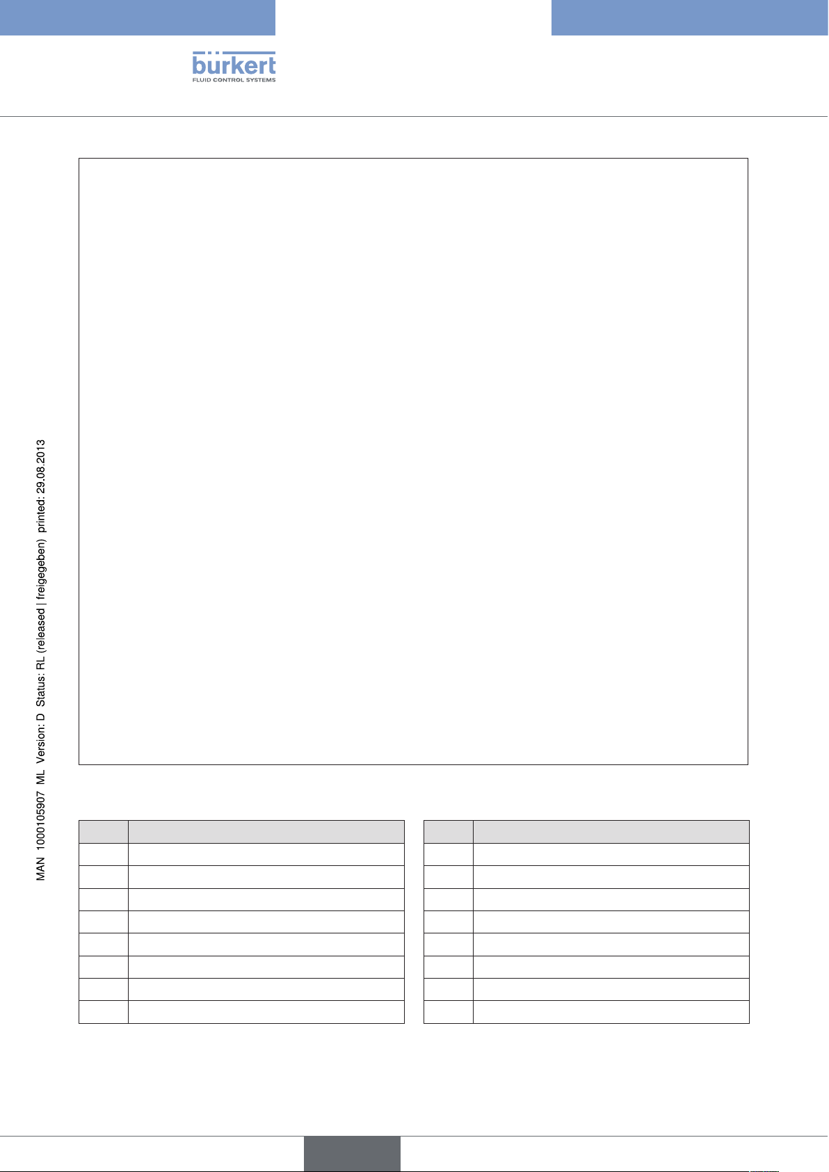
Figure 2: Exploded view of motor 100 – 300 Nm
No. Designation No. Designation
1 Position indicator 10 Body
2 Hood 11 Type label
3 Stainless steel screws 12 Additional limit switch
4 Motor 13 Cams
5.a* Control and power supply card 14.a* Control and power supply
5.b* Power supply card 14.b* Terminal strip for power supply
6 Gear plate 15 Threaded connection ISO M20
7 O-ring 16 Screw for earth
8 Gears 17 Mechanical limit stops
9 Handwheel 18 Control card (for variable speed actuator
only)
11
English
Page 12
Motor 600 - 1000 Nm
Type 3005
System Description
12
Figure 3: Exploded view of motor 600 - 1000 Nm
No. Designation No. Designation
1 Position indicator 9 Handwheel
2 Hood 10 Body
3 Stainless steel screws 11 Place for type label
4 Motor 13 Cams
5 Control and power supply card 15 Threaded connection ISO M20x1.5
6 Gear plate 16 Screw for earth
7 O-ring 17 Mechanical limit stops
8 Gears
English
Page 13

Type 3005
System Description
5.4. Options
• Three-position rotary actuator (180°)
• Rotation angle 180° or 270°
• Rotary actuator with feedback potentiometer
- Potentiometer with resistance values 100 W, 1 KW, 5 KW or 10 KW
- Analogue feedback via signal: 0 – 10 V, 0 – 20 mA, 4 – 20 mA
• Rotary actuator with emergency current model
(see Chapter “9. Option: Rotary actuators with emergency current model”).
• 2 additional limit switches
English
13
Page 14
Type 3005
Technical Data
6. TECHNICAL DATA
6.1. Conformity
The explosion-protected electric rotary actuator Type 3005 conforms to the EC Directives according to the Declaration of Conformity.
6.2. Standards
The applied standards which are used to demonstrate compliance with the EC Directives are listed in the EC
type test certificate and/or the EC Declaration of Conformity.
6.3. Operating Conditions
Ambient temperature: -20 °C ... +70 °C
-10 °C ... + 40 °C Emergency reset
Protection class: IP67 in accordance with EN 60529 with cable bushing ISO 20 or protective
flap
NOTE!
• Avoid heat sources which may result in the permitted temperature range to be exceeded.
6.4. Identification
The rotary actuator is fitted with a type label which uniquely identifies the device and indicates the most important
technical data.
Do not remove the type label from the rotary actuator!
It is essential for identification when installing and servicing the device.
The warranty is void without the type label.
14
English
Page 15
Type 3005
Technical Data
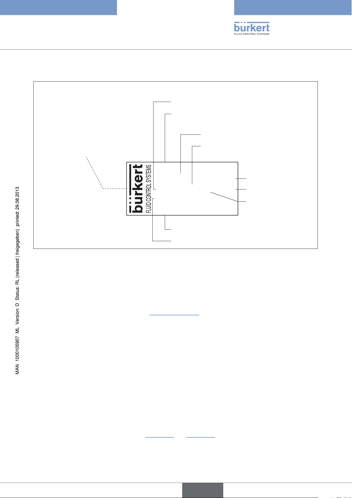
6.4.1. Description of the type label.
Torque
Type designation
Operating voltage
Actuating time for 90°
3005
24V AC/DC ED 50%
150Nm 30 Sek 90° 45W
IP67 OF 076688/ 107
179 725
Identification number
Protection class
Figure 4: Example of type label labelling
6.5. General Technical Data
6.5.1. Mechanical data
Dimensions: See chapter “6.5.2. Dimensions”
Weight: 25 – 75 Nm; 3.1 kg
100 – 300 Nm; 5.6 kg
600 - 1000 Nm; 20 kg
Duty cycle
Output
Actuating angle
S45/07
Body material: Body made of aluminium
Cover made of polyamide (optionally aluminium)
Axles and screws made of stainless steel
Gears made of galvanized steel
Actuating angle: 90° (optional 180°, 270°) ± 5°
Duty cycle: 50% at maximum torque (optionally 80%)
Manual emergency actuation: with open-end wrench on faces of the axle (up to 75 Nm);
by handwheel (from 100 Nm)
Working modes: Open/Closed mode or Three points mode
(see figure “Figure 17” and “Figure 18”)
English
15
Page 16
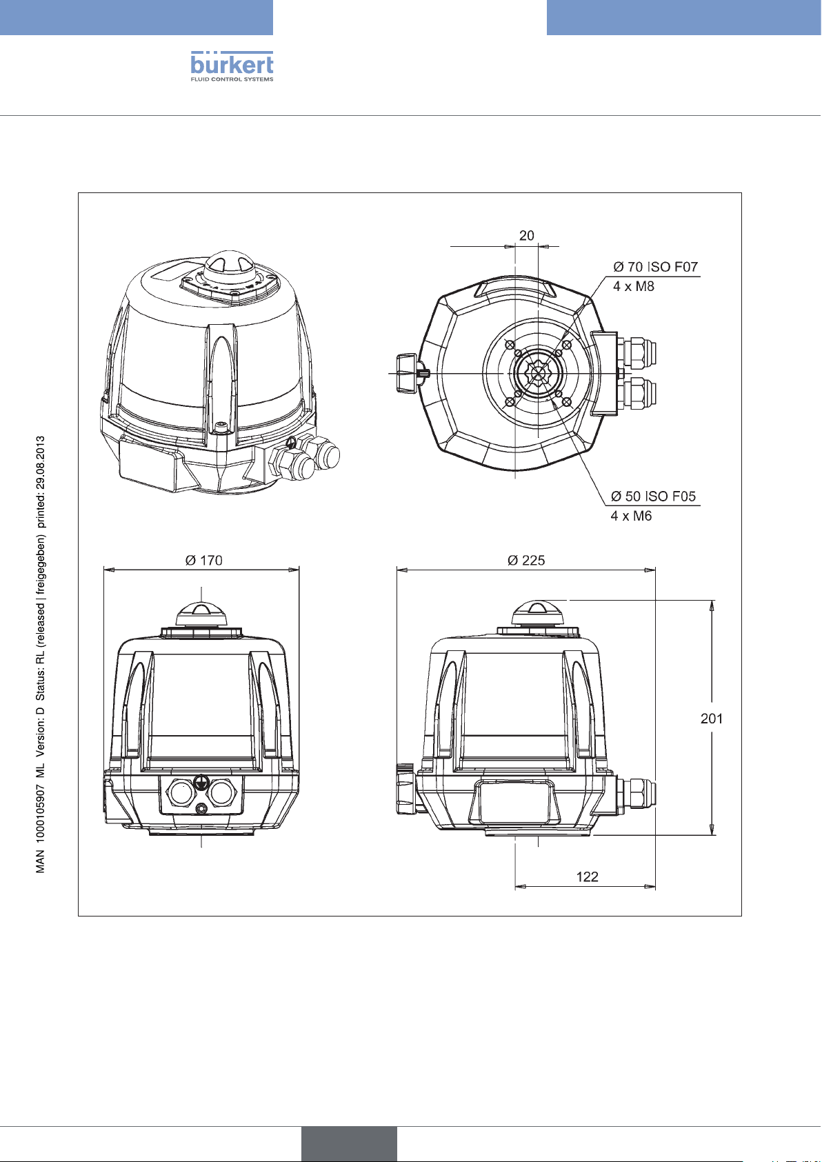
6.5.2. Dimensions
Motor 25 - 75 Nm
Type 3005
Technical Data
16
Figure 5: Dimensions Type 3005 at torque 25 – 75 Nm
English
Page 17
Type 3005
Technical Data
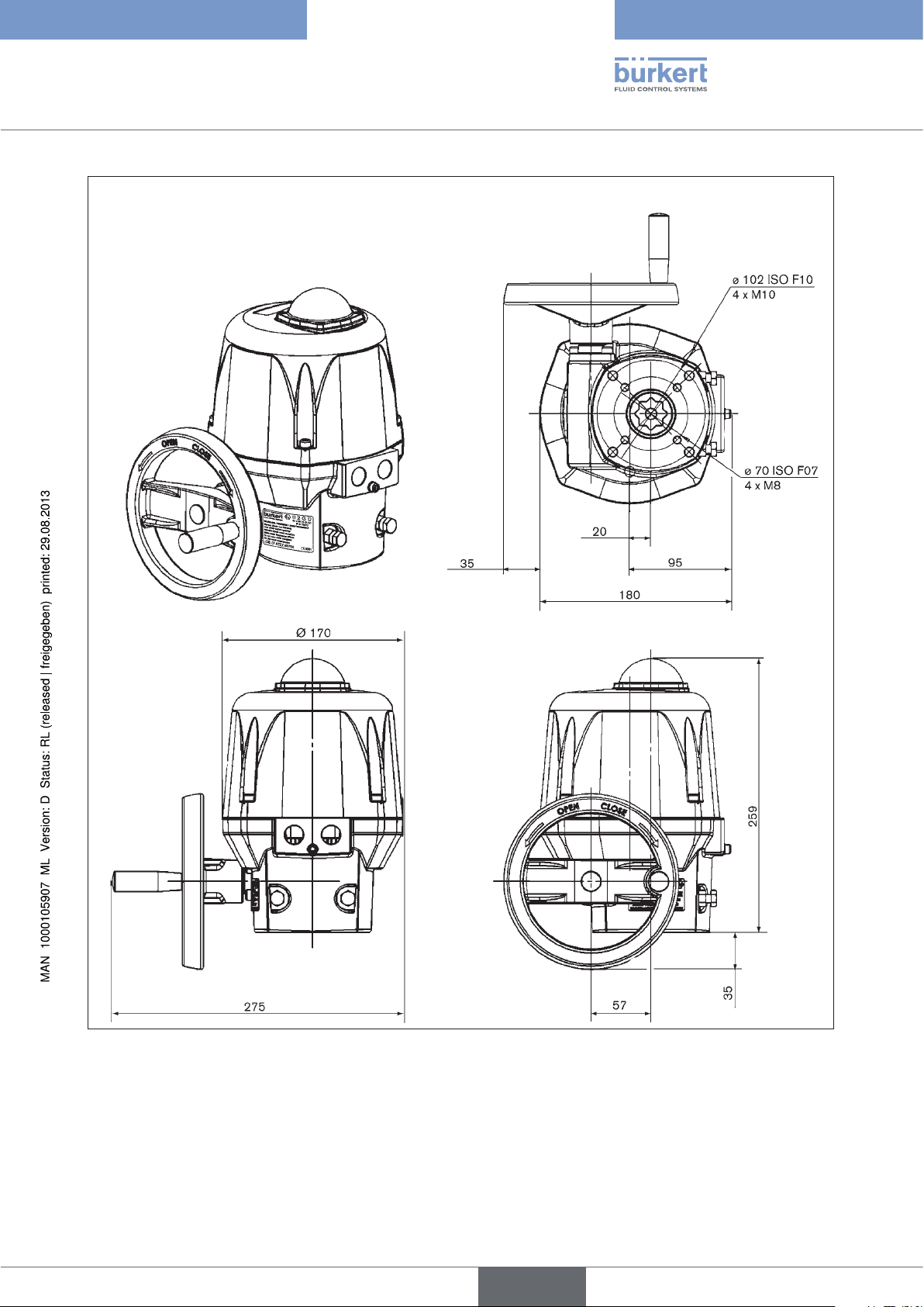
Motor 100 – 300 Nm
Figure 6: Dimensions Type 3005 at torque 100 – 300 Nm
17
English
Page 18
Motor 600 - 1000 Nm
Type 3005
Technical Data
18
Figure 7: Dimensions Type 3005 at torque 600 - 1000 Nm
English
Page 19
Type 3005
Technical Data
6.5.3. Electrical data
Connections: 2 threaded connections ISO 20
Limit switches: 2 limit switches for the motor
2 potential-free limit switches (for position feedback)
Output: max. 250 V AC / 5 A
Electrical data for standard version without analogue signal and position controller version with 4 – 20 mA,
0 – 20 mA or 0 – 10 V analogue input signal
Torque [Nm] 90° actuating time [s] Power input [W]
Voltage / frequency
[V / Hz]
25 7 45 100-240 / 50/60 (100-350 DC)
15-30 AC (12-48 DC
1)
45 15 45 100-240 / 50/60 (100-350 DC)
15-30 AC (12-48 DC
1)
75 20 45 100-240 / 50/60 (100-350 DC)
15-30 AC (12-48 DC
1)
100 15 45 100-240 / 50/60 (100-350 DC)
15-30 AC (12-48 DC
1)
150 30 45 100-240 / 50/60 (100-350 DC)
15-30 AC (12-48 DC
1)
300 60 45 100-240 / 50/60 (100-350 DC)
15-30 AC (12-48 DC
1)
600 38 250 100-240 / 50/60 (100-350 DC)
15-30 AC (12-48 DC
1)
1000 38 250 100-240 / 50/60 (100-350 DC)
15-30 AC (12-48 DC
1)
)
)
)
)
)
)
)
)
We recommend an actuator designed with 1.5 times the maximum torque of the fitting (with 2 times
the maximum torque for variable speed actuators)
1) The operating voltage must not drop below 11.5 V
19
English
Page 20
Type 3005
Installation
7. INSTALLATION
7.1. Safety instructions
DANGER!
Risk of electric shock!
There is a serious risk of injury when reaching into the device.
• Always disconnect the power and secure it from re-activation before removing the cover, disconnecting the
gears or using the lever.
• Connect several rotary actuators always with phase separation via a switch!
• Protect the rotary actuators with a mains-operated fuse!
• Observe applicable accident prevention and safety regulations for electrical equipment!
WARNING!
Danger - improper installation!
Improper installation may result in injuries as well as damage to the device and the area around it.
• Installation may be carried out by authorised technicians only and with the appropriate tools!
• Observe the specifications in chapter “6. Technical Data”.
Danger due to unintentional activation of the device!
Unintentional activation of the device during installation may result in injuries and damage.
• Take appropriate measures to prevent the device from being accidentally actuated.
7.2. Installing the rotary actuator
The rotary actuator is supplied with the presetting <Closed>.
The rotary actuator can be fitted to a ball valve or flap valve via the following fastening options:
• ISO F05 (4 x M6 with a flange Ø of 50 mm)
• ISO F07 (4 x M8 with a flange Ø of 70 mm)
• ISO F10 (4 x M10 with a flange Ø of 102 mm)
20
• ISO F12 (4 x M12 with a flange Ø of 125 mm)
7.2.1. Shaft end
The sizes of the inner star shape of the shaft end depend on the size of the actuator. Only the standard size of the
inner star shape is enclosed with each actuator (see table).
Actuator size [Nm] Standard size of the inner star shape [mm]
25 17 / 11
45 / 75 17 / 14
English
Page 21
Type 3005
Installation
Actuator size [Nm] Standard size of the inner star shape [mm]
100 / 150 / 300 22 / 17
600 / 1000 36
The shaft ends of the ball valves / flap valves can be adjusted to the supplied star shape size with reducing
sleeves which can be purchased separately.
The order numbers and an overview of the available reducing sleeves can be found in the chapter entitled
“13. Accessories”.
Further information is available from your Bürkert sales office.
Important information for continuous function:
Do not attach rotary actuator head first!
Otherwise the medium may run out of the fitting into the actuator.
The required installation height of the rotary actuator above the ball valve / flap valve can be found in the
chapter entitled Dimensions. Specify an additional distance of 100 mm.
Installation procedure:
Figure 8: Standard installation
→ Ensure that the ball valve / the flap valve is in its closed position.
→ Carefully connect the rotary actuator to the shaft of the ball valve / flap valve.
When connecting the rotary actuator, ensure that it is not twisted and that the fastening threads of the rotary
actuator are covered by the fastening bores of the ball valve / flap valve.
→ Screw the fastening screws into the fastening threads of the rotary actuator and tighten them firmly
(max. 3 Nm).
7.2.2. Set mechanical end position limit
(actuators 100 – 1000 Nm)
The mechanical end position limits have been preset at the factory and glued on with Loctite. However, they
can be adjusted by turning the screws M8 Pos. 17 (see “Figure 2” und “Figure 3”). Then the nuts must be
glued on again.
→ Loosen the M8 nuts on the mechanical limit stops 17 (see “Figure 2” und “Figure 3”) and adjust the mechanical
end position limits.
→ Glue nuts on again with Loctite (e. g. Loctite 577).
English
21
Page 22
7.2.3. Adjusting limit switch contacts
The two upper limit switch contacts have been set to 0 – 90° at the factory.
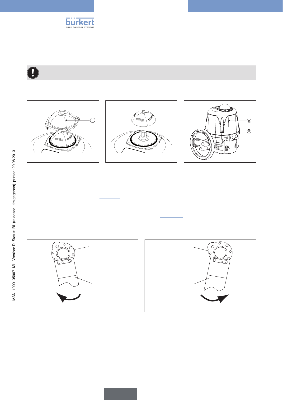
Removing position indicator and hood
1
Type 3005
Installation
Figure 9: Removing glass hood Figure 10: Removing position
indicator
Procedure:
Figure 11: Removing hood
→ Remove glass hood of the position indicator 1 including the sealing ring by loosening the four fastening screws
and remove the glass hood (see “Figure 9”).
→ Remove position indicator (see “Figure 10”).
→ Remove hood 2 by loosening the four fastening screws 3 (see “Figure 11”).
Adjusting cams for limit switch contacts
Cam
Key
Cam
Key
22
Adjustment travel
Figure 12: Adjusting limit switch clockwise Figure 13: Adjusting limit switch anti-clockwise
Procedure:
Adjustment travel
→ Adjust the two upper cams with a suitable key (see “Figure 12” and “Figure 13”).
→ On completion of the adjustment work, re-attach the hood 3, the position indicator, the seal and the glass hood 1.
English
Page 23
Type 3005
Installation
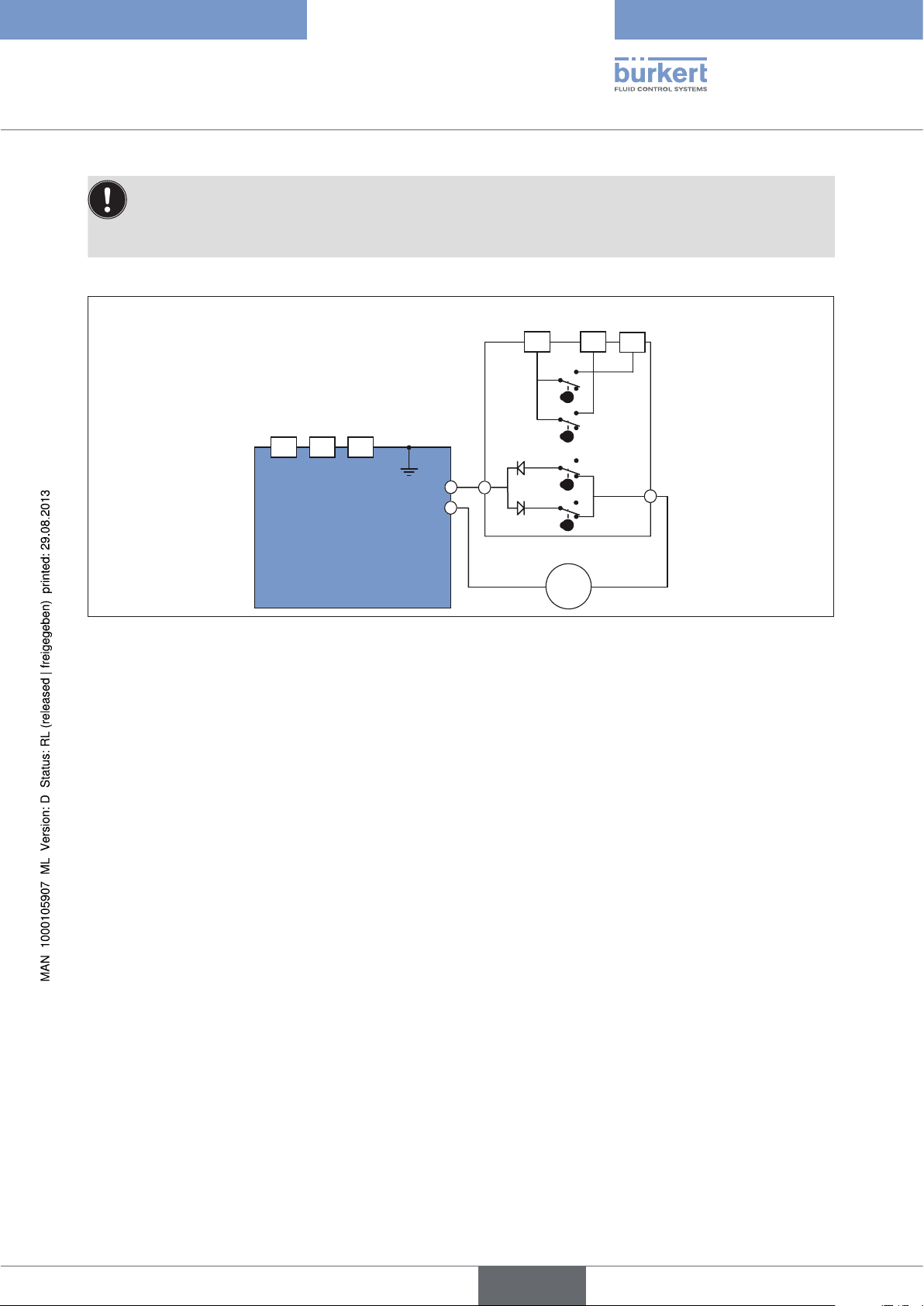
The rotary actuator is supplied ex works with the following settings:
• The limit switch CLOSED (FCF) is actuated by the cam (closed position).
• The limit switch OPEN (FCO) is preset to a rotation angle of 90°.
Feedback
Power supply and control
Figure 14: Internal wiring of actuator
4-6 5
FC2
2 31
T/E
C
C
A
FC1
D
FCF
D
FC0
Motor
=
7
B
English
23
Page 24
Type 3005
Installation
8. INSTALLATION
8.1. Safety instructions
WARNING!
Danger - improper installation!
Improper installation may result in injuries as well as damage to the device and the area around it.
• Fluid and electrical installations may be carried out by authorised technicians only and with the appropriate tools!
Danger due to unintentional activation of the equipment!
Unintentional activation of the equipment during installation work may result in injuries and/or damage.
• Take appropriate measures to prevent the equipment from being unintentionally activated.
8.2. Electrical installation
DANGER!
Risk of electric shock!
There is a serious risk of injury when reaching into the device.
• Before starting work, always switch off the power supply and safeguard to prevent re-activation!
• Observe applicable accident prevention and safety regulations for electrical equipment!
• Attach earthing cable via the earthing screw!
Check on the type label of the rotary actuator whether the indicated voltage corresponds with the mains
voltage.
Cables with a diameter of 7 to 12 mm are permitted for the electrical installation. The utilized cables must
have an upper limit temperature of at least 80 °C.
Use only ATEX-approved cables and cable bushings.
Preparatory work:
→ Remove stainless steel screws 3 for the hood 2 and carefully remove the hood (see “Figure 1”, “Figure 2” and
“Figure 3”).
8.2.1. Earth connection on outside or inside
24
The earthing cable for the power supply and control must be attached with the earthing screw 16 (M5) to the outer
body (see “Figure 1”, “Figure 2” and “Figure 3”).
Procedure:
→ Loosen earthing screw 16 and attach eyelet of the earthing cable to the earthing screw (see “Figure 1”, “Figure
2” and “Figure 3”).
→ Optionally the earthing screw can be connected to Pos. A of the power supply card.
→ To do this, loosen earthing screw and attach eyelet of the earthing cable with the earthing screw (see “Figure
15” and “Figure 16”).
English
Page 25
Type 3005
Installation
8.2.2. 100-240 V AC (100-350 V DC) or 15-30 V AC (12-48 V DC)
standard version
The power supply voltage of the actuator is 15-30 V AC (12-48 V DC) or 100-240 V AC
(100-350 V DC).
Always observe the specifications on the type label!
H
F
E
D
C B C
A
Figure 15: Power supply circuit board 15-30 V 50/60
Hz (12-48 V DC)
G
H
C B C
A
Figure 16: Power supply circuit board 100-240 V
50/60 Hz (100-350 V DC)
G
F
E
D
No. Designation No. Designation
Screw for earthing
A
Connections for control and power supply
B
Fuse
C
LED 2: Error message
E
LED 3: Power on
F
Connection for error feedback (24 V DC - 3
G
A max)
LED 1: Microprocessor OK
D
Connection 24 V DC
H
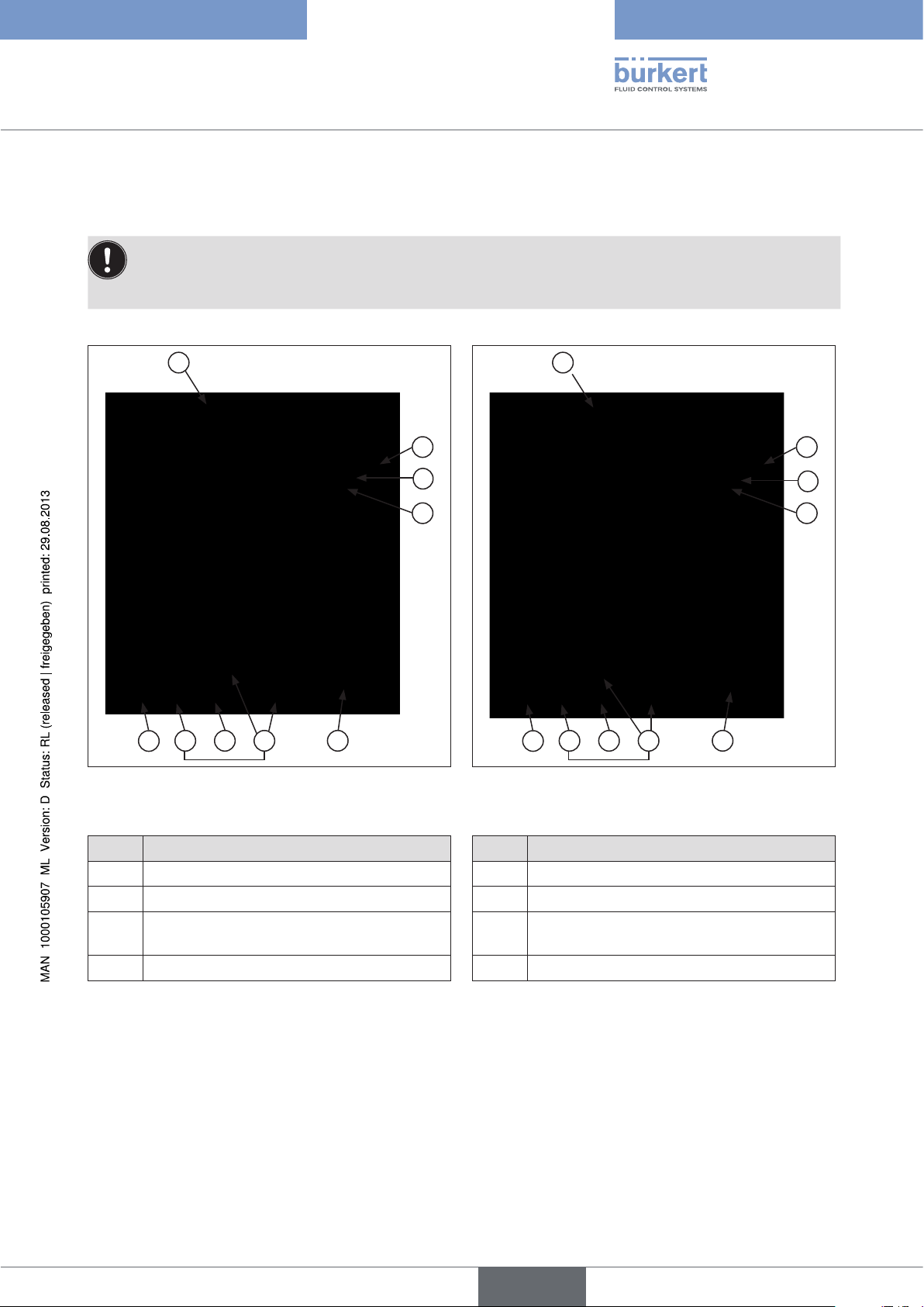
The rotary actuator can be connected and operated in two different modes:
1. Three points mode
2. Open / Closed mode
English
25
Page 26
N
Ph
N
Ph
Type 3005
Installation
-
1
Figure 17: Three points mode Figure 18: Open / Closed mode / Emergency current
+
Auf Zu
2 3
T/E
-
1
model
+
Auf
T/E
32
If voltage is applied simultaneously to terminals 2 and 3, terminal 2 is the leading one and the actuator
moves to the OPEN position.
Procedure:
→ Loosen left cable gland 15 (see “Figure 1” and “Figure 2”) and feed through the cable to be connected.
→ Connect cable according to the required control type (see “Figure 17” and “Figure 18”) to the terminal strip Pos.
B of the power supply card (see “Figure 15” and “Figure 16”).
Operating principle for Open / Closed mode (see “Figure 18”) :
• Switch open = actuator closes
• Switch closed = actuator opens
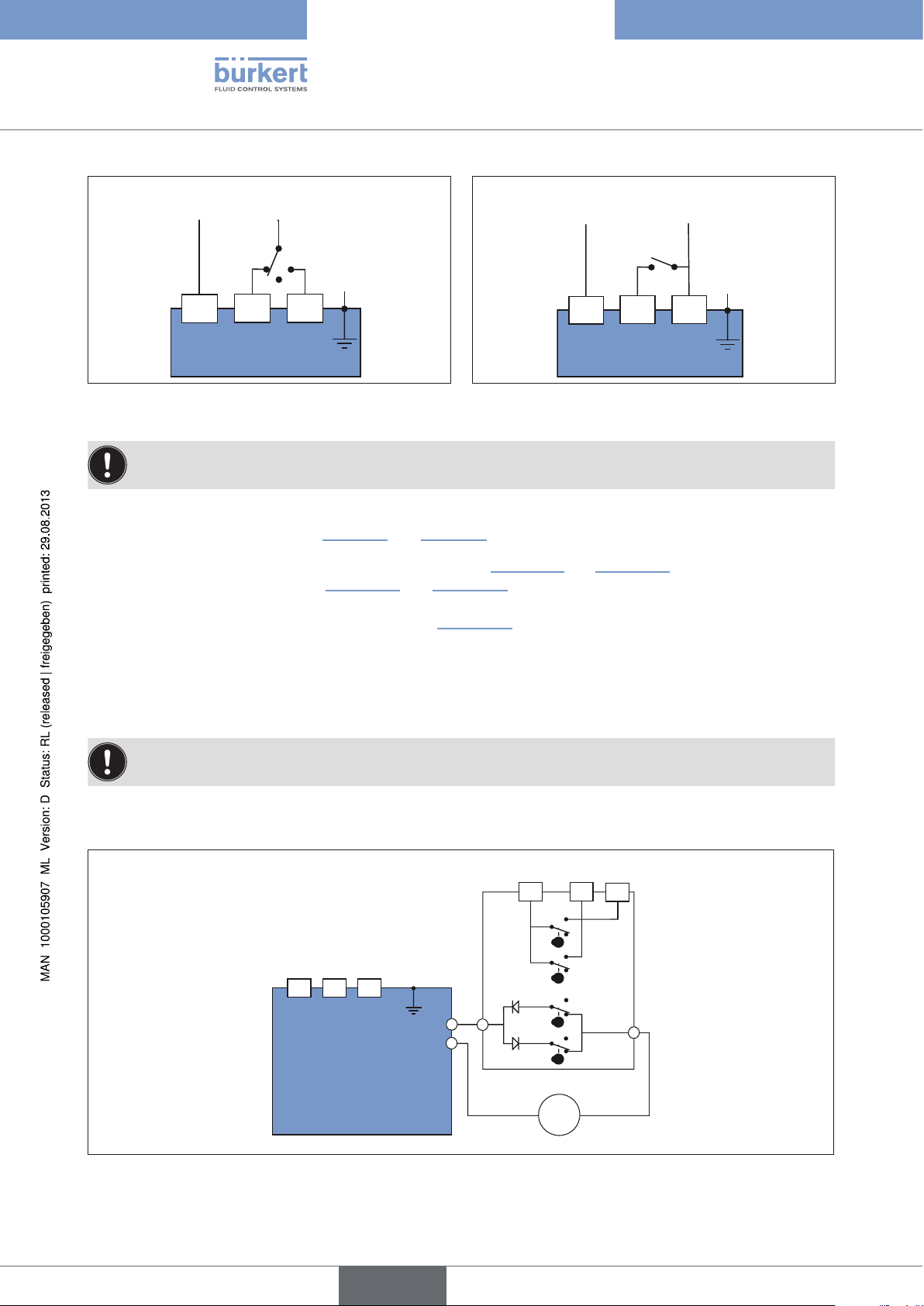
Connecting feedback
The limit switches for the feedback are suitable for a maximum voltage of 250 V AC/DC – 5 A.
The rotary actuator features two additional limit switch contacts which are supplied by the factory in an open position.
These can be used for the feedback of the rotary actuator.
Feedback
4-6 5
FC2
Power supply and control
2 31
T/E
C
C
A
FC1
D
FCF
D
FC0
Motor
=
7
B
26
Figure 19: Internal wiring of actuator
English
Page 27
N-Ph
Type 3005
Installation
The limit switch contacts are actuated via two cams no. 13 (see “Figure 1”, page 10 and “Figure 2”, page 11).
• The white cam is used to record the opening process (FC1).
• The black cam is used to record the closing process (FC2).
Procedure:
→ Connect cable to the terminal strip 12 (see “Figure 1”, page 10 and “Figure 2”, page 11) according to the
schematic (see “Figure 19”).
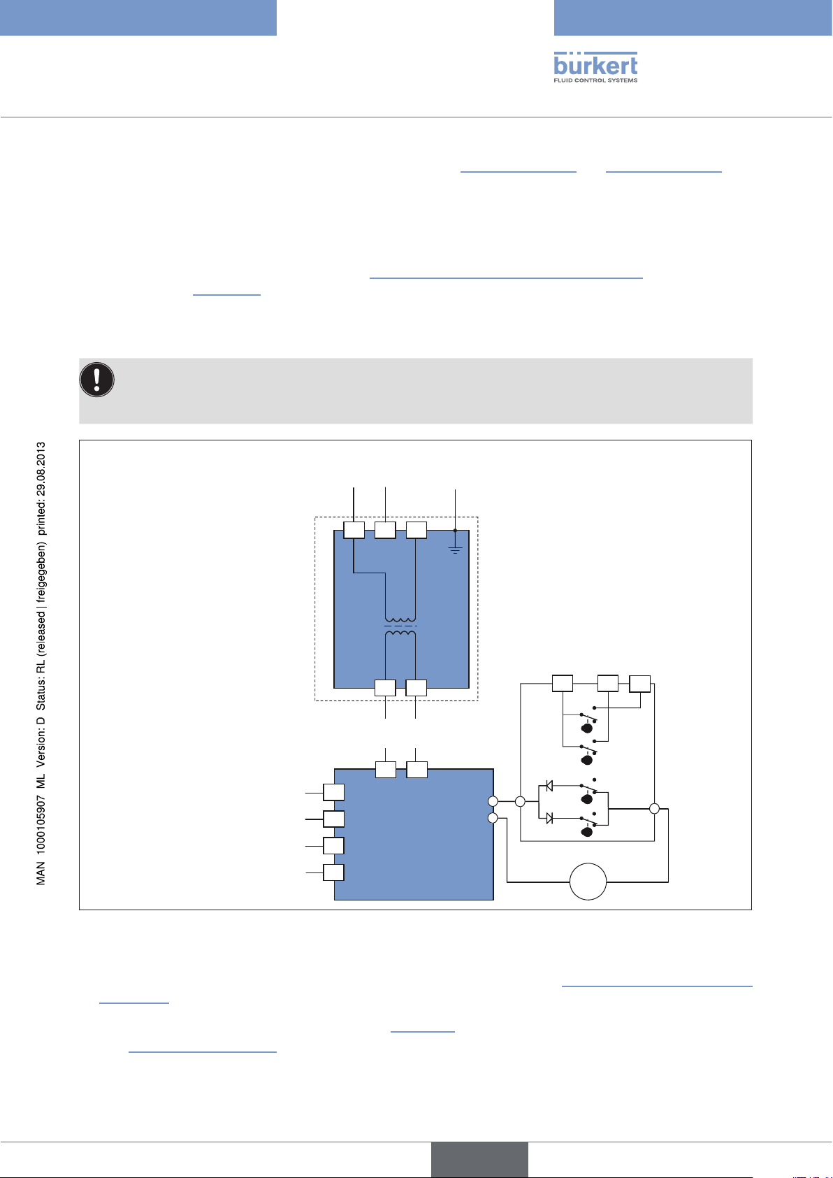
8.2.3. Version with analog signal input
The power supply voltage of the actuator is 15-30 V AC (12-48 V DC) or 100-240 V AC
(100-350 V DC).
Always observe the specifications on the type label!
Power supply
100-240 V AC
(100-350 V DC)
or
15-30 V AC
(12-48 V DC)
Power supply
24 V DC
+
16
Input
-
15
-
14
Feedback
+
13
0 – 20 mA / 4 – 20 mA / 0 – 10 V
+
2
17 18
N-Ph
T/E
31
Feedback
4-6 5
FC2
+
FC1
1817
C
A
D
C
FCF
D
FC0
Motor
=
7
B
Figure 20: Circuit diagram
Procedure:
→ Loosen left cable gland 15 and feed through the cable to be connected (see “Figure 1”, page 10 and “Figure
2”, page 11).
→ Connect cable according to the circuit diagram (see “Figure 20”) to the terminal strip Pos. 14 of the power supply card
(see “Figure 1” and “Figure 2”).
English
27
Page 28
Type 3005
Installation
Connecting feedback
The limit switches for the feedback are suitable for a maximum voltage of 250 V AC/DC – 5 A.
The rotary actuator features two limit switch contacts which are supplied by the factory in an open position. These
can be used for the feedback of the rotary actuator.
The limit switch contacts are actuated via two cams no. 13 (see “Figure 1” and “Figure 2”).
• The white cam is used to record the opening process (FC1).
• The black cam is used to record the closing process (FC2).
Procedure:
→ Connect cable to the terminal strip 12 (see “Figure 1” and “Figure 2”) according to the schematic (see “Figure
20”).
8.2.4. Electric wiring 400 V three-phase current
Power supply
Command
KM1: Open
KM2: Close
Feedback
28
Figure 21: Electric wiring 400 V three-phase current
No. Description No. Description
FCO Open limit switch TLF Torque switch: closing
FCF Close limit switch M Motor
FC1 Auxiliary limit switch 1 F Heating resistor
FC2 Auxiliary limit switch 2 H Motor thermoswitch
TLO Torque switch: opening
English
Page 29
Type 3005
Installation
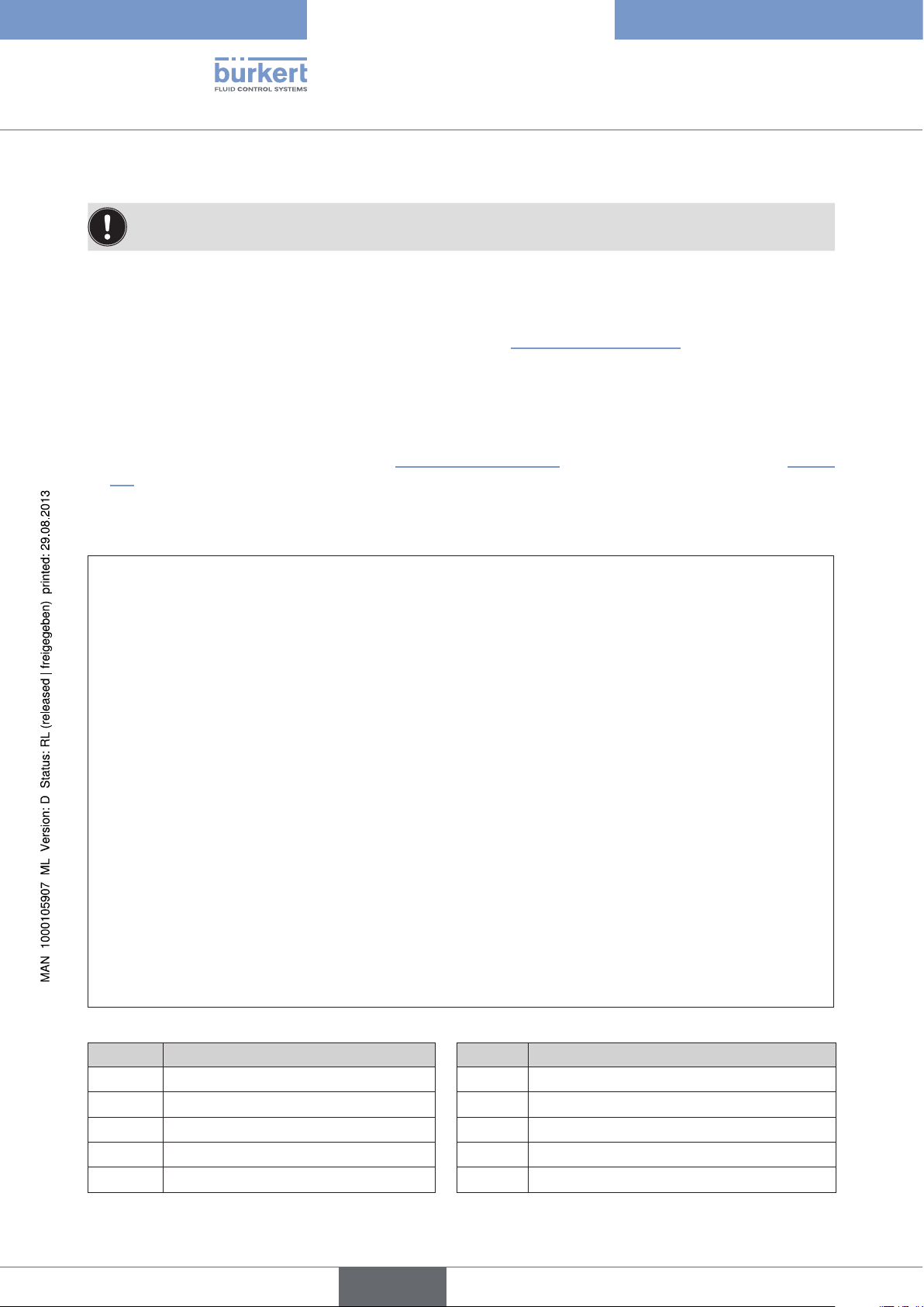
8.3. Control card
For rotary actuator with analogue control
D E C F
I
B
H
G
J
Figure 22: Control card (24 V DC)
A
K
L
M
N
No. Designation No. Designation
24V DC power supply
A
Connection terminals transducer
B
Connection terminals feedback
C
Adjusting button <MEM>
D
Adjusting button <CLOSE>
E
Adjusting button <OPEN>
F
K1 plug-in jumper
G
K2 plug-in jumper
H
K3 plug-in jumper
I
Green and red LEDs
J
Yellow LED: power supply display
K
Potentiometer
L
Connection motor
M
Connection heating resistor
N
English
29
Page 30
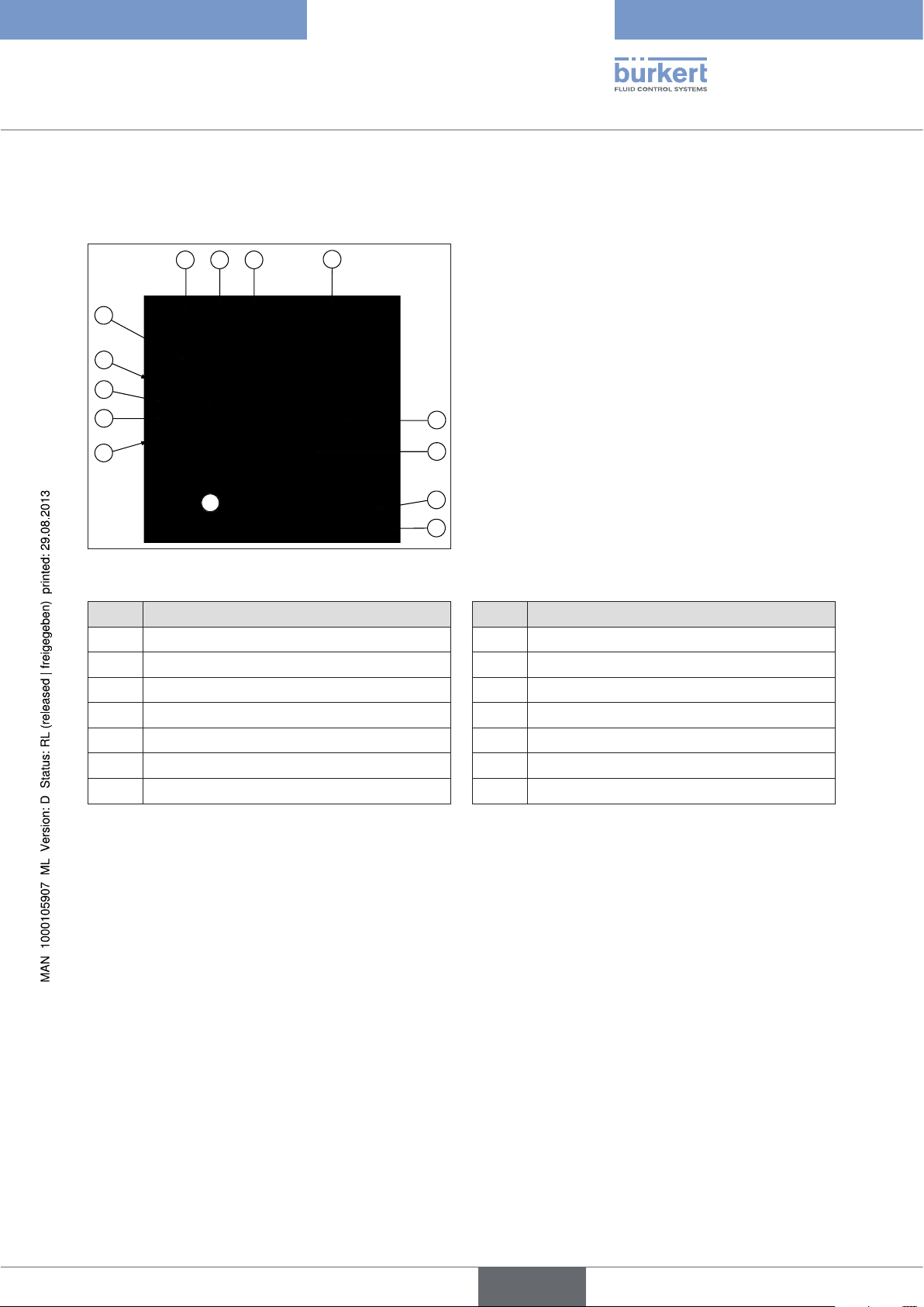
8.3.1. The position of the plug-in jumpers
Type 3005
Installation
ON
(turned on)
Figure 23: Plug-in jumper K1 / K2 Figure 24: Plug-in jumper K3
OFF
(turned off)
OFF
Plug-in jumper K1 Plug-in jumper K2
Transducer Feedback
A B A B
0 - 10 V 0 - 10 V
0 - 10 V 0 - 20 mA
0 - 10 V 4 - 20 mA
4 - 20 mA 0 - 10 V
4 - 20 mA 0 - 20 mA
4 - 20 mA 4 - 20 mA
4 - 20 mA* 0 - 10 V
4 - 20 mA* 0 - 20 mA
4 - 20 mA* 4 - 20 mA
ON OFF ON OFF OFF
ON OFF OFF ON OFF
ON OFF OFF ON ON
OFF ON ON OFF OFF
OFF ON OFF ON OFF
OFF ON OFF ON ON
ON OFF ON OFF OFF
ON OFF OFF ON OFF
ON OFF OFF ON ON
Figure 25: Plug-in jumper K3
ON
Plug-in
jumper
K3
30
* Version with emergency reset
English
Page 31

Type 3005
Installation
8.3.2. Parameterization steps
Specify direction of rotation of the shut-off valve
Normal direction of rotation (preset)
→ Press <OPEN> push-button and switch on the card (hold down
push-button).
G
Reverse direction of rotation
R
Specify control signal type
Control signal when voltage 0 – 10 V
R
The GREEN LED lights up.
→ Release <OPEN> push-button and disconnect the card from the power
supply.
→ Press <CLOSE> push-button and switch on the card (hold down
push-button).
The RED LED lights up.
→ Release <CLOSE> push-button and disconnect the card from the
power supply.
→ Press <MEM> push-button and switch on the card (hold down
push-button).
The RED LED lights up 3x.
→ Release <MEM> push-button and disconnect the card from the
power supply.
Control signal when current 0 – 20 mA
→ Press <MEM> and <OPEN> push-buttons and switch on the card
(hold down push-button).
R
The RED LED lights up 3x.
→ Release <MEM> and <OPEN> push-buttons and disconnect the
card from the power supply.
Control signal when current 4 – 20 mA (preset)
→ Press <MEM> and <CLOSE> push-buttons and switch on the card
(hold down push-button).
R
The RED LED lights up 3x.
→ Release <MEM> and <CLOSE> push-buttons and disconnect the
card from the power supply.
31
English
Page 32

Learning mode
R
R
Specify end positions
Type 3005
Installation
→ Press <OPEN> and <CLOSE> push-buttons and switch on the card
(hold down push-button).
The RED and the GREEN LEDs light up.
G
R
→ Release <OPEN> and <CLOSE> push-buttons.
Both LEDs go out.
Learning mode is selected.
→ Press <CLOSE> push-button to move the shut-off valve into the
R
closed position.
The RED LED lights up.
→ Press <MEM> and <CLOSE> push-buttons to save the closed
position.
The RED LED lights up 2x.
G
The GREEN LED lights up.
The GREEN LED lights up 2x.
All positions are now saved.
8.3.3. Normal operation
Display normal operation
G
G
The GREEN LED lights up 3x to indicate that the start process has been
implemented correctly.
In normal operation the GREEN LED lights up when the rotary actuator
opens the shut-off valve.
→ Press <OPEN> push-button to move the shut-off valve into the open
position.
→ Press <MEM> and <OPEN> push-buttons to save the open position.
→ Disconnect the card from the power supply.
→ Switch on card.
R
G
The RED LED lights up when the rotary actuator closes the shut-off valve.
R
If neither of the LEDs is lit, the actuator is not actuated.
The RED and the GREEN LEDs light up if the torque is too high and the
G R
rotary actuator stops.
→ Change direction of rotation of the rotary actuator or switch over the
voltage OPEN/CLOSED to restart the rotary actuator!
32
English
Page 33

Type 3005
Option: Rotary actuators with
emergency current model
9. OPTION: ROTARY ACTUATORS WITH
EMERGENCY CURRENT MODEL
9.1. Description
The emergency current model consists of an integrated safety block for emergency reset.
24 V battery block
Wiring
Screws ST2.2 x 6.5
Electronic printed circuit board
Figure 26: Safety block of the emergency current model; parts designation
9.2. Technical Data
Voltage 24 V DC
Nominal current 0.8 A
Maximum current 2.4 A
Charging time 14 h
English
33
Page 34

Type 3005
Option: Rotary actuators with
emergency current model
9.3. Electrical connection of safety block
9.3.1. Connection diagram
Battery block
Wire colour
F+
red
Wire colour
E-
black
Load state
feedback
Actuator
wiring
Suggestet customer
wiring
KM1 - Customer
contactor switch
On / Off Mode
F+
E-
65
66
Safety block
Loaded battery: closed
contact
24 V
AC/DC
N
Total security mode
17
18
Control and power supply card
17
100V-240V 50/60 Hz (100V-350V DC)
15V-30V 50/60 Hz (12V-48V DC)
18
B
1 2 3 1 2 3
N
A1
KM1
A2
Open
Ph
B
A
N
A
D1
D2
Open
Ph
Figure 27: Connection diagram of emergency reset
Configuration A or B
A - standard mode: If the actuator is controlled with a programmable controller, the feedback of the charge state
can be connected to it.
34
B - mode - increased safety (if the feedback relay is used, terminals 65 and 66): The actuator does not actuate
the valve unless the safety block is loaded.
English
Page 35

Type 3005
Option: Rotary actuators with
emergency current model
9.3.2. Description of the electronic printed circuit board
LED green
LED red
Connection for feedback signal (charge state)
Battery block connection
Figure 28: Illustration: Electronic printed circuit board
Description of LED status
LED Status Description
Green lit Mains power operation
flashing Battery operation
Red lit Battery is charged
flashing Battery is being charged
24 V DC Connection
English
35
Page 36

Type 3005
Option: Rotary actuators with
emergency current model
9.4. Installation of safety block into the actuator drive
4 fastening screws ST2.2 x 6.5
Figure 29: Illustration: installation of safety block into the actuator drive
→ Fasten the safety block of the emergency current model onto the actuator drive with 4
(see illustration “Figure 29”).
→ Connect the battery in this order:
1. F+ (wire color red)
2. E- (wire color black)
→ Connect the power supply in this order:
1. terminal 18
2. terminal 17
(see “Figure 28: Illustration: Electronic printed circuit board”).
36
English
Page 37

Type 3005
Start-Up
10. START-UP
10.1. Safety instructions
WARNING!
Danger due to improper operation!
Improper operation may result in injuries as well as damage to the device and the area around it.
• Before start-up, ensure that the operating personnel are familiar with and completely understand the contents of
the operating instructions.
• In particular observe the safety instructions and intended use.
• The device/the system may be started by adequately trained personnel only.
10.2. Procedure
→ Ensure that connections and settings are implemented properly according to chapter “7. Installation”.
→ Check whether the rotary actuator and the fitting are in a defined end position, otherwise the fitting may lock.
In this case the actuator switches off automatically.
English
37
Page 38

Type 3005
Operation and function
11. OPERATION AND FUNCTION
11.1. Safety instructions
WARNING!
Risk of electric shock!
There is a serious risk of injury when reaching into the device.
• Switch off the power before operating the rotary actuator manually.
• Observe applicable accident prevention and safety regulations for electrical equipment!
WARNING!
Danger due to improper operation!
Improper operation may result in injuries as well as damage to the device and the area around it.
• The operating personnel must know and have understood the contents of the operating instructions.
• In particular observe the safety instructions and intended use.
• The device/the system may be operated by adequately trained personnel only.
WARNING!
Hazardous situation due to manual intervention!
During manual intervention the process may switch to an undefined state, resulting in hazardous situations.
• Following manual intervention, ensure that the process is restarted in a defined or controlled manner!
11.2. Manual operation
Before operating the rotary actuator manually, ensure that the power supply has been interrupted!
The handwheel can be operated manually without disengaging it. No work steps in particular need to be implemented.
38
English
Page 39

Type 3005
Maintenance, Troubleshooting
12. MAINTENANCE, TROUBLESHOOTING
12.1. Safety instructions
DANGER!
Risk of electric shock!
There is a serious risk of injury when reaching into the device.
• Before starting work, always switch off the power supply and safeguard to prevent re-activation!
• Observe applicable accident prevention and safety regulations for electrical equipment!
WARNING!
Danger due to improper maintenance work!
Improper maintenance may result in injuries as well as damage to the device and the surrounding area.
• Maintenance work may be carried out by authorised technicians only and with the appropriate tools!
Danger due to unintentional activation of the equipment!
Unintentional activation of the equipment during maintenance and repair work may result in injuries and/or
damage.
• Take appropriate measures to prevent the equipment from being unintentionally activated.
12.2. Maintenance Work
The rotary actuator is maintenance-free when operated according to the instructions indicated in this manual.
12.3. Malfunctions
Malfunction Remedial action
The rotary actuator does not function
(initial start-up)
The rotary actuator is jammed in the
OPEN position
→ Check the power supply.
→ Check the connections according to the supplied circuit
diagram.
→ Check the power supply.
→ Check the connections according to the supplied circuit
diagram.
→ Check whether the movement of the electric valve is obstructed.
English
39
Page 40

Malfunction Remedial action
The valve does not fully open or close
The rotary actuator is jammed in the
CLOSED position
Type 3005
Maintenance, Troubleshooting
→ Check the power supply.
→ Check the connections according to the supplied circuit
diagram.
→ Check the limit switches.
→ Check whether an overload has occurred due to excessively
high torque on the valve (our rotary actuators feature electronic
overload protection).
If yes: Interrupt the power supply for approx. 5 minutes.
→ Check the power supply.
→ Check the connections according to the supplied circuit
diagram.
→ Check whether the movement of the electric valve is obstructed.
40
English
Page 41

Type 3005
Accessories
13. ACCESSORIES
CAUTION!
Risk of injury and/or damage by the use of incorrect parts!
Incorrect accessories and unsuitable replacement parts may cause injuries and damage the device and the surrounding area.
• Use only original accessories and original spare parts supplied by Bürkert.
Designation Order no.
Key for adjusting the limit switches 679 946
Reducing sleeve star/square 14/9 mm 665 288
Reducing sleeve star/square 14/11 mm 665 289
Reducing sleeve star/star 22/14 mm 666 684
Reducing sleeve star/square 22/17 mm 684 858
Reducing sleeve square/square 17/14 mm 665 290
Adapter outer square 14/10 mm 668 234
English
41
Page 42

Type 3005
14. PACKAGING AND TRANSPORT
NOTE!
Transport damages!
• Inadequately protected equipment may be damaged during transport.
• During transportation protect the device against wet and dirt in shock-resistant packaging.
• Avoid the action of heat and cold which can lead to temperatures above or below the admissible storage
temperature.
15. STORAGE
NOTE!
Incorrect storage may damage the device.
• Store the device in a dry and dust-free location!
• Storage temperature. -20 °C ...+70 °C.
16. DISPOSAL
→ Dispose of the device and packaging in an environmentally friendly manner.
NOTE!
Damage to the environment caused by device components contaminated with media.
• Observe the relevant disposal and environmental protection regulations.
Note:
Observe national waste disposal regulations.
42
English
Page 43

Typ 3005
Elektromotorischer Drehantrieb Typ 3005
Inhalt
1. DIE BEDIENUNGSANLEITUNG .................................................................................................................................................45
1.1. Darstellungsmittel ..............................................................................................................................................................45
2. BESTIMMUNGSGEMÄSSE VERWENDUNG .......................................................................................................................46
2.1. Beschränkungen .................................................................................................................................................................46
3. GRUNDLEGENDE SICHERHEITSHINWEISE .....................................................................................................................47
4. ALLGEMEINE HINWEISE ..............................................................................................................................................................48
4.1. Kontaktadressen .................................................................................................................................................................48
4.2. Gewährleistung ....................................................................................................................................................................48
4.3. Informationen im Internet ...............................................................................................................................................48
5. SYSTEMBESCHREIBUNG ............................................................................................................................................................49
5.1. Vorgesehener Einsatzbereich ......................................................................................................................................49
5.2. Allgemeine Beschreibung ..............................................................................................................................................49
5.3. Explosionsdarstellung ......................................................................................................................................................50
5.4. Optionen ..................................................................................................................................................................................53
6. TECHNISCHE DATEN .....................................................................................................................................................................54
6.1. Konformität.............................................................................................................................................................................54
6.2. Normen .....................................................................................................................................................................................54
6.3. Zulassungen ..........................................................................................................................................................................54
6.4. Betriebsbedingungen .......................................................................................................................................................54
6.5. Kennzeichnung ....................................................................................................................................................................54
6.6. Allgemeine Technische Daten .....................................................................................................................................55
7. MONTAGE .............................................................................................................................................................................................60
7.1. Sicherheitshinweise ..........................................................................................................................................................60
7.2. Montage des Drehantriebs ............................................................................................................................................60
8. INSTALLATION ...................................................................................................................................................................................64
deutsch
43
Page 44

Typ 3005
8.1. Sicherheitshinweise ..........................................................................................................................................................64
8.2. Elektrische Installation.....................................................................................................................................................64
8.3. Regelkarte ...............................................................................................................................................................................69
9. OPTION: DREHANTRIEBE MIT NOTSTROMVARIANTE ................................................................................................73
9.1. Beschreibung ........................................................................................................................................................................73
9.2. Technische Daten ...............................................................................................................................................................73
9.3. Elektrischer Anschluss des Sicherheitsblocks ..................................................................................................74
9.4. Einbau des Sicherheitsblocks in den Stellantrieb ............................................................................................76
10. INBETRIEBNAHME ..........................................................................................................................................................................77
10.1. Sicherheitshinweise ..........................................................................................................................................................77
10.2. Vorgehensweise ..................................................................................................................................................................77
11. BEDIENUNG UND FUNKTION ...................................................................................................................................................78
11.1. Sicherheitshinweise ..........................................................................................................................................................78
11.2. Manuelle Bedienung .........................................................................................................................................................78
12. WARTUNG, FEHLERBEHEBUNG .............................................................................................................................................79
12.1. Sicherheitshinweise ..........................................................................................................................................................79
12.2. Wartungsarbeiten ................................................................................................................................................................79
12.3. Störungen ...............................................................................................................................................................................79
13. ZUBEHÖR .............................................................................................................................................................................................81
14. VERPACKUNG, TRANSPORT .....................................................................................................................................................82
15. LAGERUNG ..........................................................................................................................................................................................82
16. ENTSORGUNG ...................................................................................................................................................................................82
44
deutsch
Page 45

Typ 3005
Die Bedienungsanleitung
1. DIE BEDIENUNGSANLEITUNG
Die Bedienungsanleitung beschreibt den gesamten Lebenszyklus des Gerätes. Bewahren Sie diese Anleitung so auf,
dass sie für jeden Benutzer gut zugänglich ist und jedem neuen Eigentümer des Gerätes wieder zur Verfügung steht.
WARNUNG!
Die Bedienungsanleitung enthält wichtige Informationen zur Sicherheit!
Das Nichtbeachten dieser Hinweise kann zu gefährlichen Situationen führen.
• Die Bedienungsanleitung muss gelesen und verstanden werden.
1.1. Darstellungsmittel
GEFAHR!
Warnt vor einer unmittelbaren Gefahr!
• Bei Nichtbeachtung sind Tod oder schwere Verletzungen die Folge.
WARNUNG!
Warnt vor einer möglicherweise gefährlichen Situation!
• Bei Nichtbeachtung drohen schwere Verletzungen oder Tod.
VORSICHT
Warnt vor einer möglichen Gefährdung!
• Nichtbeachtung kann mittelschwere oder leichte Verletzungen zur Folge haben.
HINWEIS!
Warnt vor Sachschäden!
• Bei Nichtbeachtung kann das Gerät oder die Anlage beschädigt werden.
Bezeichnet wichtige Zusatzinformationen, Tipps und Empfehlungen.
Verweist auf Informationen in dieser Bedienungsanleitung oder in anderen Dokumentationen.
→ markiert einen Arbeitsschritt, den sie ausführen müssen.
deutsch
45
Page 46

Typ 3005
Bestimmungsgemäße Verwendung
2. BESTIMMUNGSGEMÄSSE VERWENDUNG
WARNUNG!
Bei nicht bestimmungsgemäßem Einsatz des elektrischen Drehantriebs Typ 3005 können Gefahren für
Personen, Anlagen in der Umgebung und die Umwelt entstehen.
• Der Drehantrieb kann z. B. zur Betätigung von Armaturen, insbesondere Kugelhähnen oder Absperrklappen
verwendet werden.
• Für den Einsatz sind die in den Vertragsdokumenten und der Bedienungsanleitung spezifizierten zulässigen
Daten, Betriebs- und Einsatzbedingungen zu beachten die im Kapitel „5. Systembeschreibung“ beschrieben
sind.
• Der elektrische Drehantrieb darf nur in Verbindung mit von Bürkert empfohlenen bzw. zugelassenen Fremdgeräten und Komponenten eingesetzt werden (z. B. ATEX zugelassene Komponenten).
• Voraussetzungen für den sicheren und einwandfreien Betrieb sind sachgemäßer Transport, sachgemäße
Lagerung und Installation, sowie sorgfältige Bedienung und Instandhaltung.
• Das Gerät nur bestimmungsgemäß einsetzen.
2.1. Beschränkungen
Bei der Ausfuhr des Systems/Geräts gegebenenfalls bestehende Beschränkungen beachten.
Der elektrische Drehantrieb Typ 3005 wurde unter Einbeziehung der anerkannten sicherheitstechnischen
Regeln entwickelt und entspricht dem Stand der Technik. Trotzdem können Gefahren entstehen.
Das Gerät nur in einwandfreiem Zustand und unter Beachtung der Bedienungsanleitung betreiben.
46
deutsch
Page 47

Typ 3005
Grundlegende Sicherheitshinweise
3. GRUNDLEGENDE SICHERHEITSHINWEISE
Diese Sicherheitshinweise berücksichtigen keine:
• Zufälligkeiten und Ereignisse, die bei Montage, Betrieb und Wartung der Geräte auftreten können.
• Ortsbezogenen Sicherheitsbestimmungen, für deren Einhaltung, auch in Bezug auf das Montagepersonal, der
Betreiber verantwortlich ist.
Gefahr durch elektrische Spannung!
Bei Eingriffen in das Gerät besteht akute Verletzungsgefahr.
• Vor Eingriffen in das Gerät in jedem Fall die Spannung abschalten und diese vor Wiedereinschalten sichern!
• Mehrere elektrische Drehantriebe immer mit Phasentrennung über einen Schalter anschließen.
• Das Gerät durch eine netzabhängige Sicherung schützen.
• Die geltenden Unfallverhütungs- und Sicherheitsbestimmungen für elektrische Geräte beachten!
Explosionsgefahr!
Bei bestimmten Geräteausführungen besteht bei Öffnung des Gerätes im explosionsgeschützten Bereich
Explosionsgefahr.
• Die Sicherheitshinweise auf dem Typschild beachten!
Explosionsgefahr durch statische Aufladung!
Bei plötzlicher Entladung elektrostatisch aufgeladener Geräte oder Personen besteht im Ex-Bereich
Explosionsgefahr.
• Durch geeignete Maßnahmen sicherstellen, dass es im Ex-Bereich zu keinen elektrostatischen Aufladungen
kommen kann.
• Die Geräteoberfläche durch leichtes Abwischen mit einem feuchten oder antistatischen Tuch reinigen.
Allgemeine Gefahrensituationen.
Zum Schutz vor Verletzungen ist zu beachten:
• Dass die Anlage nicht unbeabsichtigt betätigt werden kann.
• Typ 3005 nicht in explosionsgefährdeten Bereichen einsetzen (in diesem Fall Typ 3004 verwenden).
• Das Gehäuse nicht mechanisch belasten (z. B. durch Ablage von Gegenständen oder als Trittstufe).
• Keine äußerlichen Veränderungen an den Gerätegehäusen vornehmen. Gehäuseteile und Schrauben nicht
lackieren.
• Antrieb nicht mit dem Deckel nach unten (kopfüber) einbauen.
• Installations- und Instandhaltungsarbeiten dürfen nur von autorisiertem Fachpersonal mit geeignetem Werkzeug ausgeführt werden.
• Nach einer Unterbrechung der elektrischen oder pneumatischen Versorgung ist ein definierter oder kontrollierter Wiederanlauf des Prozesses zu gewährleisten.
• Das Gerät darf nur in einwandfreiem Zustand und unter Beachtung der Bedienungsanleitung betrieben
werden.
• Für die Einsatzplanung und den Betrieb des Gerätes müssen die allgemeinen Regeln der Technik eingehalten
werden.
deutsch
47
Page 48

Typ 3005
Allgemeine Hinweise
4. ALLGEMEINE HINWEISE
4.1. Kontaktadressen
Deutschland
Bürkert Fluid Control System
Sales Center
Chr.-Bürkert-Str. 13-17
D-74653 Ingelfingen
Tel. : +49 (0)7940 - 10 91 111
Fax: +49 (0)7940 - 10 91 448
E-mail: info@de.buerkert.com
International
Die Kontaktadressen finden Sie auf den letzten Seiten der gedruckten Bedienungsanleitung.
Außerdem im Internet unter: www.buerkert.com
4.2. Gewährleistung
Voraussetzung für die Gewährleistung ist der bestimmungsgemäße Gebrauch des elektischen Drehantriebs Typ
3005 unter Beachtung der spezifizierten Einsatzbedingungen.
4.3. Informationen im Internet
Bedienungsanleitungen und Datenblätter zum Typ 3005 finden Sie im Internet unter:
www.buerkert.de
48
deutsch
Page 49

Typ 3005
Systembeschreibung
5. SYSTEMBESCHREIBUNG
5.1. Vorgesehener Einsatzbereich
Der elektromotorische Drehantrieb Typ 3005 (im Folgenden als Drehantrieb bezeichnet) wurde entwickelt, um
Kugelhahn- oder Klappenventile mit Vierteldrehung zu steuern. Optional ist der Antrieb auch mit einem Drehwinkel
von 180° und 270° erhältlich.
5.2. Allgemeine Beschreibung
Das Basisgerät kann durch die modulare Konstruktion mit vielen Optionen erweitert werden.
Optionen zur Erweiterung des Basisgerätes finden Sie im Kapitel „5.4. Optionen“.
Der Drehantrieb ist ein kompaktes und leistungsstarkes Stellantriebssystem, das eine lange Lebensdauer gewährleistet. Der Drehantrieb ist für Gleich- oder Wechselstrom mit unterschiedlicher Leistung konzipiert und für Drehmomente von 25 bis 1000 Nm (Antrieb mit Analogsignal 20 - 300 Nm) ausgelegt.
Die verwendeten Werkstoffe gewährleisten einen wartungsfreien Betrieb und stellen eine niedrige thermische
Belastung sicher. Alle Drehantriebe sind in der Standardausführung mit einer Handnotbetätigung und zwei zusätzlichen Endschaltern ausgestattet und vom Hersteller getestet. Die Endschalter wurden auf 0 ... 90° Schwenkbetrieb
eingestellt.
Der elektromotorische Drehantrieb ist als Auf/Zu- oder Regelantrieb erhältlich. Er ist mit folgenden Komponenten
kombinierbar:
• Edelstahl Kugelhahn mit zweiteiligem Gehäuse (Typ 2651),
• Edelstahl Kugelhahn mit dreiteiligem Gehäuse (Typ 2654),
• Kunststoff Kugelhahn (Typ 2657),
• Metall Klappenventil (Typ 2671),
• Kunststoff Klappenventil (Typ 2674).
Die Antriebsrichtung ist im gleichen Betriebsvorgang nicht umkehrbar. Ein automatischer Rücklauf des Drehantriebs
erfolgt nicht.
Über das Handrad am Drehantrieb ist auch ein mechanischer Betrieb möglich. Im elektrischen Betrieb dreht sich
das Handrad nicht mit.
deutsch
49
Page 50

Typ 3005
Systembeschreibung
5.3. Explosionsdarstellung
Motor 25 - 75 Nm Motor 25 - 75 Nm mit Regelkarte
1
2
3
4
5.a
6
7
8
9
10
11
14.a
12
13
15
16
1
2
3
4
5.b
6
7
8
9
10
11
17
12
13
14.b
15
16
50
Bild 1: Explosionsdarstellung Motor 25 - 75 Nm
Pos. Bezeichnung Pos. Bezeichnung
1 Stellungsanzeige 10 Gehäuse
2 Haube 11 Platz für Typschild
3 Edelstahl-Schrauben 12 Zusätzlicher Endschalter
4 Motor 13 Nocken
5.a* Steuerung und Stromversorgung Karte 14.a* Steuerung und Spannungsversorgung
5.b* Stromversorgungskarte 14.b* Klemmleiste für Spannungsversorgung
6 Getriebeplatte 15 Kabelverschraubung ISO M20
7 O-Ring 16 Schraube für Erde
8 Getriebe 17 Regelkarte (nur bei Regelantrieb)
9 Schaltknopf
deutsch
Page 51

Typ 3005
Systembeschreibung
Motor 100 - 300 Nm Motor 100 - 300 Nm mit Regelkarte
Bild 2: Explosionsdarstellung Motor 100 - 300 Nm
Pos. Bezeichnung Pos. Bezeichnung
1 Stellungsanzeige 10 Gehäuse
2 Haube 11 Typschild
3 Edelstahl-Schrauben 12 Zusätzlicher Endschalter
4 Motor 13 Nocken
5.a* Steuerung und Stromversorgung Karte 14.a* Steuerung und Spannungsversorgung
5.b* Stromversorgungskarte 14.b* Klemmleiste für Spannungsversorgung
6 Getriebeplatte 15 Kabelverschraubung ISO M20
7 O-Ring 16 Schraube für Erde
8 Getriebe 17 Mechanische Endanschläge
9 Handrad 18 Regelkarte (nur bei Regelantrieb)
51
deutsch
Page 52

Motor 600 - 1000 Nm
Typ 3005
Systembeschreibung
52
Bild 3: Explosionsdarstellung Motor 600 - 1000 Nm
Pos. Bezeichnung Pos. Bezeichnung
1 Stellungsanzeige 9 Handrad
2 Haube 10 Gehäuse
3 Edelstahl-Schrauben 11 Platz für Typschild
4 Motor 13 Nocken
5 Steuerung und Stromversorgung Karte 15 Innengewinde M20x1,5
6 Getriebeplatte 16 Schraube für Erde
7 O-Ring 17 Mechanische Endanschläge
8 Getriebe
deutsch
Page 53

Typ 3005
Systembeschreibung
5.4. Optionen
• Dreistellungsdrehantrieb (180°)
• Drehwinkel 180° oder 270°
• Drehantrieb mit Rückmelde-Potentiometer
- Potentiometer mit Widerstandswerten 100 W, 1 KW, 5 KW oder 10 KW
- Analoge Rückmeldung über Signal: 0 ... 10 V, 0 ... 20 mA, 4 ... 20 mA
• Drehantrieb mit Notstromvariante (siehe Kapitel „9. Option: Drehantriebe mit Notstromvariante“)
• 2 zusätzliche Endschalter
deutsch
53
Page 54

Typ 3005
Technische Daten
6. TECHNISCHE DATEN
6.1. Konformität
Der elektromotorische Drehantrieb Typ 3005 ist konform zu den EG-Richtlinien entsprechend der
Konformitätserklärung.
6.2. Normen
Die angewandten Normen, mit denen die Konformität mit den EG-Richtlinien nachgewiesen wird, sind in der EGBaumusterprüfbescheinigung und/oder der EG-Konformitätserklärung nachzulesen.
6.3. Betriebsbedingungen
Umgebungstemperatur: -20 °C ... +70 °C
-10 °C ... +40 °C Notrückstellung
Schutzart: IP67 nach EN 60529 mit Kabelverschraubung ISO 20 oder Schutzkappe
HINWEIS!
• Die Wärmequellen vermeiden, die zur Überschreitung des zulässigen Temperaturbereichs führen können.
6.4. Kennzeichnung
Der Drehantrieb ist mit einem Typschild versehen, das eine eindeutige Identifikation ermöglicht und die wichtigsten
technischen Daten erkennen lässt.
Das Typschild nicht vom Drehantrieb entfernen!
Es ist für die Identifikation bei Installation und Instandhaltung von entscheidender Bedeutung.
Ohne Typschild erlischt die Gewährleistung.
54
deutsch
Page 55

Typ 3005
Technische Daten
6.4.1. Beschreibung des Typschildes
Drehmoment
Typbezeichnung
Betriebsspannung
Stellzeit für 90°
3005
24V AC/DC ED 50%
150Nm 30 Sek 90° 45W
IP67 OF 076688/ 107
179 725
Identnummer
Schutzart
Bild 4: Beschreibung des Typschildes (Beispiel)
6.5. Allgemeine Technische Daten
6.5.1. Mechanische Daten
Abmessungen: Siehe Kapitel „6.5.2. Abmessungen“
Gewicht: 25 -75 Nm; 3,1 kg
100 - 300 Nm; 5,6 kg
600 - 1000 Nm; 20 kg
Einschaltdauer
Leistung
Stellwinkel
S45/07
Gehäusematerial: Gehäuse - Aluminium
Deckel - Polyamid (Aluminium optional)
Achsen und Schrauben - Edelstahl
Getriebe - verzinkter Stahl
Stellwinkel: 90° (optional 180°, 270°) ± 5°
Einschaltdauer: 50 % bei maximalem Drehmoment (optional 80 %)
Handnotbetätigung: mit Gabelschlüssel an Flächen der Achse (bis 75 Nm);
durch Handrad (ab 100 Nm)
Arbeitsmodi: Auf/Zu Modus oder Drei Punkt Modus (siehe „Bild 17“ und „Bild 18“)
deutsch
55
Page 56

6.5.2. Abmessungen
Motor 25 - 75 Nm
Typ 3005
Technische Daten
56
Bild 5: Abmessungen Typ 3005 mit Drehmoment 25 - 75 Nm
deutsch
Page 57

Technische Daten
Motor 100 - 300 Nm
Typ 3005
Bild 6: Abmessungen Typ 3005 mit Drehmoment 100 - 300 Nm
deutsch
57
Page 58

Motor 600 - 1000 Nm
Typ 3005
Technische Daten
58
Bild 7: Abmessungen Typ 3005 mit Drehmoment 600 - 1000 Nm
deutsch
Page 59

Typ 3005
Technische Daten
6.5.3. Elektrische Daten
Anschlüsse: 2 Gewindeanschlüsse ISO 20
Endschalter: 2 Endschalter für den Motor
2 potenzialfreie Endschalter (für Stellungsrückmeldung)
Leistung: max. 250 V AC / 5 A
Elektrische Daten für Standardausführung ohne Analogsignal und Stellungsreglerausführung mit
4 ... 20 mA, 0 ... 20 mA oder 0 ... 10 V Analogsignaleingang
Drehmoment
[Nm]
90° Stellzeit
[s]
Leistungsaufnahme
[W]
Spannung / Frequenz
[V / Hz]
25 7 45 100-240 / 50/60 (100-350 DC)
15-30 AC (12-48 DC
45 15 45 100-240 / 50/60 (100-350 DC)
15-30 AC (12-48 DC
75 20 45 100-240 / 50/60 (100-350 DC)
15-30 AC (12-48 DC
100 15 45 100-240 / 50/60 (100-350 DC)
15-30 AC (12-48 DC
150 30 45 100-240 / 50/60 (100-350 DC)
15-30 AC (12-48 DC
300 60 45 100-240 / 50/60 (100-350 DC)
15-30 AC (12-48 DC
600 38 250 100-240 / 50/60 (100-350 DC)
15-30 AC (12-48 DC
1000 38 250 100-240 / 50/60 (100-350 DC)
15-30 AC (12-48 DC
1)
)
1)
)
1)
)
1)
)
1)
)
1)
)
1)
)
1)
)
Wir empfehlen eine Antriebsauslegung mit dem 1,5-fachen des maximalen Drehmoments der Armatur
(bei Regelantrieben mit dem 2-fachen des maximalen Drehmoments).
1) Die Betriebsspannung darf 11,5 V nicht unterschreiten
59
deutsch
Page 60

Typ 3005
Montage
7. MONTAGE
7.1. Sicherheitshinweise
GEFAHR!
Gefahr durch elektrische Spannung!
Bei Eingriffen in das Gerät besteht akute Verletzungsgefahr.
• Schalten Sie in jedem Fall die Spannung ab und sichern Sie diese vor Wiedereinschalten, bevor Sie den
Deckel entfernen, das Getriebe trennen oder den Hebel benutzen.
• Schließen Sie mehrere Drehantriebe immer mit Phasentrennung über einen Schalter an!
• Schützen Sie die Drehantriebe durch eine netzabhängige Sicherung!
• Beachten Sie die geltenden Unfallverhütungs- und Sicherheitsbestimmungen für elektrische Geräte!
WARNUNG!
Gefahr durch unsachgemäße Montage!
Unsachgemäße Montage kann zu Verletzungen sowie zu Schäden am Gerät und seiner Umgebung führen.
• Die Montage darf nur durch autorisiertes Fachpersonal und mit geeignetem Werkzeug durchgeführt werden!
• Beachten Sie die Angaben im Kapitel „6. Technische Daten“.
Gefahr durch unbeabsichtigte Betätigung des Geräts!
Ungewolltes Ingangsetzen des Geräts bei der Montage kann zu Verletzungen und Sachschäden führen.
• Durch geeignete Maßnahmen verhindern, dass das Gerät nicht unbeabsichtigt betätigt werden kann.
7.2. Montage des Drehantriebs
Der Drehantrieb wird mit der Voreinstellung <Geschlossen> ausgeliefert.
Die Montage des Drehantriebs auf einen Kugelhahn bzw. Klappenventil erfolgt über folgende Befestigungsvarianten:
• ISO F05 (4 x M6 bei einem Flansch - Ø von 50 mm)
• ISO F07 (4 x M8 bei einem Flansch - Ø von 70 mm)
• ISO F10 (4 x M10 bei einem Flansch - Ø von 102 mm)
60
• ISO F12 (4 x M12 bei einem Flansch - Ø von 125 mm)
7.2.1. Wellenende
Die Größen der Innensternform des Wellenendes ist von der Antriebsgröße abhängig. Jedem Antrieb ist nur die
Standardgröße der Innensternform beigelegt (siehe Tabelle).
Antriebsgröße [Nm] Standardgröße der Innensternform [mm]
25 17 / 11
45 / 75 17 / 14
deutsch
Page 61

Typ 3005
Montage
Antriebsgröße [Nm] Standardgröße der Innensternform [mm]
100 / 150 / 300 22 / 17
600 / 1000 36
Über separat zu beziehende Reduzierhülsen können die Wellenenden der Kugelhähne / Klappenventile
der mitgelieferten Sternformgröße angepasst werden.
Die Bestellnummern und eine Übersicht der verfügbaren Reduzierhülsen finden Sie im Kapitel
„13. Zubehör“.
Weitere Informationen erhalten Sie über Ihre Bürkert Vertriebsniederlassung.
Wichtiger Hinweis für die dauerhafte Funktion:
Drehantrieb nicht kopfüber anbringen!
Dabei kann das Medium aus der Armatur in den Antrieb gelangen.
Die notwendige Höhe zur Montage des Drehantriebs über dem Kugelhahn / Klappenventil entnehmen Sie
bitte den Maßen im Kapitel Abmessungen. Geben Sie einen zusätzlichen Abstand von 100 mm vor.
Montage Vorgehensweise:
Bild 8: Standardinstallation
→ Sicherstellen, dass sich der Kugelhahn / das Klappenventil in seiner geschlossenen Position befindet.
→ Drehantrieb vorsichtig auf die Welle des Kugelhahns / Klappenventils stecken.
Darauf achten, dass beim Aufstecken des Drehantriebs dieser nicht verkantet und dass sich die Befestigungsgewinde des Drehantriebs mit den Befestigungsbohrungen des Kugelhahns / Klappenventils decken.
→ Befestigungsschrauben in die Befestigungsgewinde des Drehantriebs schrauben und fest anziehen
(max. 3 Nm).
7.2.2. Einstellung der mechanischen Endlagenbegrenzung
(Antriebe 100 - 1000 Nm)
Die mechanischen Endlagenbegrenzungen sind werkseitig voreingestellt und mit Loctite verklebt. Sie können
jedoch durch Drehen der Schrauben M8 Pos. 17 (siehe „Bild 2“ und „Bild 3“) verstellt werden. Danach
müssen die Muttern wieder verklebt werden.
deutsch
61
Page 62

Typ 3005
Montage
→ Muttern M8 der mechanischen Endanschläge 17 (siehe „Bild 2“ und „Bild 3“) lösen und die mechanischen
Endlagenbegrenzungen einstellen.
→ Muttern wieder mit Loctite (z. B. Loctite 577) verkleben.
7.2.3. Einstellung der Endschalterkontakte
Die beiden oberen Endschalterkontakte sind werkseitig auf 0 - 90° eingestellt.
Stellungsanzeiger und Haube demontieren
1
Bild 9: Glashaube
Demontage
Vorgehensweise:
Bild 10: Stellungsanzeiger
Demontage
Bild 11: Haube Demontage
→ Glashaube des Stellungsanzeigers 1 inkl. den Dichtring durch Lösen der vier Befestigungsschrauben abnehmen
und die Glashaube entfernen (siehe „Bild 9“).
→ Stellungsanzeiger entfernen (siehe „Bild 10“).
→ Haube 2 durch Lösen der vier Befestigungsschrauben 3 entfernen (siehe „Bild 11“).
Nocken für Endschalterkontakte einstellen
Nocke
Schlüssel
Stellweg
Nocke
Schlüssel
Stellweg
62
Bild 13: Endschaltereinstellung gegen den
Bild 12: Endschaltereinstellung im Uhrzeigersinn
Vorgehensweise:
Uhrzeigersinn
→ Die beiden oberen Nocken mit Hilfe eines geeigneten Schlüssels einstellen (siehe „Bild 12“ und „Bild 13“).
deutsch
Page 63

Typ 3005
Montage
→ Nach Abschluss der Einstellarbeiten die Haube 3, den Stellungsanzeiger, die Dichtung und die Glashaube 1
wieder montieren.
Der Drehantrieb wird ab Werk mit folgenden Einstellungen geliefert:
• Der Endschalter ZU (FCF) ist durch die Nocke betätigt (geschlossene Position).
• Der Endschalter AUF (FCO) ist auf einen Drehwinkel von 90° voreingestellt.
Rückmeldung
Spannungsversorgung und
Steuerung
2 31
Bild 14: Interne Verdrahtung Antrieb
T/E
4-6 5
FC2
FC1
D
C
C
A
FCF
D
FC0
Motor
=
7
B
deutsch
63
Page 64

Typ 3005
Installation
8. INSTALLATION
8.1. Sicherheitshinweise
WARNUNG!
Gefahr durch unsachgemäße Installation!
Unsachgemäße Installation kann zu Verletzungen sowie zu Schäden am Gerät und seiner Umgebung führen.
• Fluidische und elektrische Installationen dürfen nur durch autorisiertes Fachpersonal und mit geeignetem Werkzeug durchgeführt werden!
Gefahr durch unbeabsichtigte Betätigung der Anlage!
Ungewolltes Ingangsetzen der Anlage während der Installationsarbeiten kann zu Verletzungen und Sachschäden
führen.
• Durch geeignete Maßnahmen verhindern, dass die Anlage unbeabsichtigt betätigt werden kann.
8.2. Elektrische Installation
GEFAHR!
Gefahr durch elektrische Spannung!
Bei Eingriffen in das Gerät besteht akute Verletzungsgefahr.
• Vor Beginn der Arbeiten in jedem Fall die Spannung abschalten und diese vor Wiedereinschalten sichern!
• Die geltenden Unfallverhütungs- und Sicherheitsbestimmungen für elektrische Geräte beachten!
• Erdungskabel über die Erdungsschraube befestigen!
Am Typschild des Drehantriebs überprüfen, ob die angegebene Spannung der Spannung des Netzes
entspricht.
Für die elektrische Installation sind Kabel mit einem Durchmesser von 7 bis 12 mm zulässig. Die verwendeten Kabel müssen eine obere Grenztemperatur von mindestens 80°C haben.
Nur ATEX zugelassene Kabelverschraubung und Kabel verwenden.
Vorbereitende Arbeiten:
→ Edelstahl-Schrauben 3 für die Haube 2 entfernen und die Haube vorsichtig abnehmen (siehe „Bild 1“, „Bild 2“
und „Bild 3“).
8.2.1. Masseanschluss außen oder innen
64
Das Erdungskabel für die Spannungsversorgung und Steuerung muss mit der Erdungsschraube 16 (M5) am Außengehäuse befestigt werden (siehe „Bild 1“, „Bild 2“ und „Bild 3“).
Vorgehensweise:
→ Erdungsschraube 16 lösen und Öse des Erdungskabels mit der Erdungsschraube befestigen
(siehe „Bild 1“, „Bild 2“ und „Bild 3“).
→ Optional kann die Erdungsschraube an Pos. A der Stromversorgungskarte angeschlossen werden.
→ Hierzu die Erdungsschraube lösen und Öse des Erdungskabels mit der Erdungsschraube befestigen (siehe
„Bild 15“ und „Bild 16“).
deutsch
Page 65

Typ 3005
Installation
8.2.2. 100-240 V AC (100-350 V DC) oder 15-30 V AC
(12-48 V DC) Standardausführung
Die Betriebsspannung des Antriebs beträgt 15-30 V AC (12-48 V DC) oder 100-240 V AC
(100-350 V DC).
Unbedingt die Angaben auf dem Typschild beachten!
H
F
E
D
C B C
A
Bild 15: Stromversorgungsplatine 15-30 V 50/60 Hz
(12-48 V DC)
G
H
F
E
D
C B C
A
Bild 16: Stromversorgungsplatine 100-240 V 50/60
Hz (100-350 V DC)
G
No. Bezeichnung No. Bezeichnung
Schraube für Erdung
A
Anschlüsse für Steuerung und
B
LED 2: Fehlermeldung
E
LED 3: Anliegende Spannung
F
Stromversorgung
C
Sicherung
Anschluss für Fehlerrückmeldung (24 V DC -
G
3 A max)
LED 1: Mikroprozessor OK
D
Anschluss 24 V DC
H
Der Drehantrieb kann in zwei verschiedenen Modi angeschlossen und betrieben werden:
1. Drei Punkt Modus
2. Auf / Zu Modus
deutsch
65
Page 66

N
Ph
N
Ph
Typ 3005
Installation
-
1
Bild 17: Drei Punkt Modus Bild 18: Auf / Zu - Modus / Notstromvariante
+
Auf Zu
2 3
T/E
-
+
Auf
T/E
1
32
Sind die Klemmen 2 und 3 gleichzeitig mit Spannung beaufschlagt, ist die Klemme 2 die führende und der
Antrieb fährt in Position AUF.
Vorgehensweise:
→ Linke Kabelverschraubung 15 (siehe „Bild 1“, „Bild 2“) lösen und das anzuschließende Kabel hindurchführen.
→ Kabel entsprechend der gewünschten Steuerungsart (siehe „Bild 17“ und „Bild 18“) an der Klemmleiste Pos.
B der Spannungsversorgungskarte anschließen (siehe „Bild 15“ und „Bild 16“).
Funktionsweise beim Auf / Zu - Modus (siehe „Bild 18“):
• Schalter geöffnet = Antrieb fährt zu
• Schalter geschlossen = Antrieb fährt auf
Rückmeldung anschließen
Die Endschalter für die Rückmeldung sind für eine maximale Spannung von 250 V AC/DC - 5 A geeignet.
Der Drehantrieb ist mit zwei zusätzlichen Endschalterkontakten versehen, die werkseitig in geöffneter Stellung ausgeliefert werden. Diese können für die Rückmeldung des Drehantriebs verwendet werden.
Rückmeldung
Spannungsversorgung und
4-6 5
FC2
7
Steuerung
2 31
T/E
C
C
A
FC1
D
FCF
D
FC0
B
66
Bild 19: Interne Verdrahtung Antrieb
Motor
=
deutsch
Page 67

N-Ph
Typ 3005
Installation
Über zwei Nocken Nr. 13 werden die Endschalterkontakte betätigt (siehe „Bild 1“ und „Bild 2“).
• Die weiße Nocke dient dazu, um die Öffnung zu erfassen (FC1).
• Die schwarze Nocke dient dazu, um das Schließen zu erfassen (FC2).
Vorgehensweise:
→ Kabel an der Klemmleiste 12 (siehe „Bild 1“ und „Bild 2“) gemäß Schema anschließen (siehe „Bild 19“).
8.2.3. Ausführung mit Analogsignaleingang
Die Betriebsspannung des Antriebs beträgt 15-30 V AC (12-48 V DC) oder 100-240 V AC
(100-350 V DC).
Unbedingt die Angaben auf dem Typschild beachten!
Spannungsversorgung
100-240 V AC
(100-350 V DC)
oder
15-30 V AC
(12-48 V DC)
Spannungsversorgung
24 V DC
+
16
Eingang
-
15
-
14
Rückmeldung
+
13
0 - 20 mA / 4 - 20 mA / 0 - 10 V
+
2
17 18
N-Ph
T/E
31
Rückmeldung
4-6 5
FC2
+
FC1
1817
C
A
D
C
FCF
D
FC0
Motor
=
7
B
Bild 20: Elektrisches Schaltschema
Vorgehensweise:
→ Linke Kabelverschraubung 15 lösen und das anzuschließende Kabel hindurchführen (siehe „Bild 1“ auf Seite
50 und „Bild 2“ auf Seite 51).
→ Kabel entsprechend dem elektrischen Schaltschema (siehe „Bild 20“) an der Klemmleiste Pos. 14 der Span-
nungsversorgungskarte anschließen (siehe „Bild 1“ und „Bild 2“).
deutsch
67
Page 68

Typ 3005
Installation
Rückmeldung anschließen
Die Endschalter für die Rückmeldung sind für eine maximale Spannung von 250 V AC/DC - 5 A geeignet.
Der Drehantrieb ist mit zwei Endschalterkontakten versehen, die werkseitig in geöffneter Stellung ausgeliefert werden.
Diese können für die Rückmeldung des Drehantriebs verwendet werden.
Über zwei Nocken Nr. 13 werden die Endschalterkontakte betätigt (siehe „Bild 1“ und „Bild 2“).
• Die weiße Nocke dient dazu, um die Öffnung zu erfassen (FC1).
• Die schwarze Nocke dient dazu, um das Schließen zu erfassen (FC2).
Vorgehensweise:
→ Kabel an der Klemmleiste 12 (siehe „Bild 1“ und „Bild 2“) gemäß Schema anschließen (siehe „Bild 20“).
8.2.4. Schaltplan 400 V Drehstrom Version
Steuerung
Spannungsversorgung
KM1: Auf
KM2: Zu
Rückmeldung
68
Bild 21: Schaltplan 400 V Drehstrom
Symbol Beschreibung Symbol Beschreibung
FCO Endschalter AUF TLF Drehmomentschalter: Geschlossen
FCF Endschalter ZU M Motor
FC1 Zusätzlicher Endschalter 1 F Motor Thermoschalter
FC2 Zusätzlicher Endschalter 2 H Heizwiderstand
TLO Drehmomentschalter: Öffnen
deutsch
Page 69

Typ 3005
Installation
8.3. Regelkarte
Für Drehantrieb mit Analogsteuerung
D E C F
I
B
H
G
J
Bild 22: Regelkarte (24 V DC)
A
K
L
M
N
No. Bezeichnung No. Bezeichnung
24 V DC Spannungsversorgung
A
Anschlussklemmen Signalgeber
B
Anschlussklemmen Rückmeldung
C
Einstellknopf <MEM>
D
Einstellknopf <CLOSE>
E
Einstellknopf <OPEN>
F
K1 Steckbrücke
G
K2 Steckbrücke
H
K3 Steckbrücke
I
Grüne und rote LEDs
J
Gelbe LED: anzeige Stromversorgung
K
Potentiometer
L
Anschluss Motor
M
Anschluss Heizwiderstand
N
deutsch
69
Page 70

8.3.1. Position der Steckbrücken
Typ 3005
Installation
ON
(eingeschaltet)
Bild 23: Steckbrücke K1 / K2 Bild 24: Steckbrücke
OFF
(ausgeschaltet)
K3 OFF
Steckbrücke K1 Steckbrücke K2
Signalgeber Rückmeldung
A B A B
0 - 10 V 0 - 10 V
0 - 10 V 0 - 20 mA
0 - 10 V 4 - 20 mA
4 - 20 mA 0 - 10 V
4 - 20 mA 0 - 20 mA
4 - 20 mA 4 - 20 mA
4 - 20 mA* 0 - 10 V
4 - 20 mA* 0 - 20 mA
4 - 20 mA* 4 - 20 mA
* Ausführung mit Notrückstellung
ON OFF ON OFF OFF
ON OFF OFF ON OFF
ON OFF OFF ON ON
OFF ON ON OFF OFF
OFF ON OFF ON OFF
OFF ON OFF ON ON
ON OFF ON OFF OFF
ON OFF OFF ON OFF
ON OFF OFF ON ON
Bild 25: Steckbrücke
K3 ON
Steck-
brücke
K3
70
deutsch
Page 71

Typ 3005
Installation
8.3.2. Parameter einstellen
Drehrichtung des Absperrventils festlegen
Normale Drehrichtung (voreingestellt)
→ Taster <OPEN> drücken und die Karte einschalten (dabei Taster
gedrückt halten).
G
Die GRÜNE LED leuchtet auf.
→ Taster <OPEN> loslassen und die Karte spannungsfrei machen.
Umgekehrte Drehrichtung
→ Taster <CLOSE> drücken und die Karte einschalten (dabei Taster
gedrückt halten).
R
Die ROTE LED leuchtet auf.
→ Taster <CLOSE> loslassen und die Karte spannungsfrei machen.
Steuersignaltyp festlegen
Steuersignal bei Spannung 0 ... 10 V
→ Taster <MEM> drücken und die Karte einschalten (dabei Taster
gedrückt halten).
R
Die ROTE LED leuchtet 3x auf.
→ Taster <MEM> loslassen und die Karte spannungsfrei machen.
Steuersignal bei Strom 0 ... 20 mA
→ Taster <MEM> und <OPEN> drücken und die Karte einschalten
(dabei die Taster gedrückt halten).
R
Die ROTE LED leuchtet 3x auf.
→ Taster <MEM> und <OPEN> loslassen und die Karte spannungsfrei
machen.
Steuersignal bei Strom 4 ... 20 mA (voreingestellt)
→ Taster <MEM> und <CLOSE> drücken und die Karte einschalten
(dabei die Taster gedrückt halten).
R
Die ROTE LED leuchtet 3x auf.
→ Taster <MEM> und <CLOSE> loslassen und die Karte spannungsfrei
machen.
deutsch
71
Page 72

Lernmodus
R
R
Endlagen festlegen
Typ 3005
Installation
→ Taster <OPEN> und <CLOSE> drücken und die Karte einschalten
(dabei die Taster gedrückt halten).
Die ROTE und die GRÜNE LED leuchten auf.
G
R
→ Taster <OPEN> und <CLOSE> loslassen.
Die beiden LED´s erlöschen.
Der Lernmodus ist gewählt.
→ Taster <CLOSE> drücken, um das Absperrventil in die geschlossene
R
Position zu bringen.
Die ROTE LED leuchtet auf.
→ Taster <MEM> und <CLOSE> drücken, um die geschlossene
Position zu speichern.
G
8.3.3. Normalbetrieb
Anzeige Normalbetrieb
G
G
Die ROTE LED leuchtet 2x auf.
→ Taster <OPEN> drücken, um das Absperrventil in die geöffnete
Position zu bringen.
Die GRÜNE LED leuchtet auf.
→ Taster <MEM> und <OPEN> drücken, um die geöffnete Position zu
speichern.
Die GRÜNE LED leuchtet 2x auf.
Alle Positionen sind nun gespeichert.
→ Karte spannungsfrei machen.
→ Karte einschalten.
Die GRÜNE LED leuchtet 3x auf, um anzuzeigen, dass der Startvorgang
korrekt ausgeführt wurde.
Im Normalbetrieb leuchtet die GRÜNE LED auf, wenn der Drehantrieb das
Absperrventil öffnet.
R
G
Die ROTE LED leuchtet auf, wenn der Drehantrieb das Absperrventil schließt.
R
Wenn keine der beiden LED´s leuchtet, so wird der Antrieb nicht angesteuert.
Die ROTE und die GRÜNE LED leuchten auf, wenn das Drehmoment zu
G R
hoch ist und der Drehantrieb stoppt.
→ Drehrichtung des Drehantriebes wechseln oder die Spannung AUF/
ZU umschalten, um den Drehantrieb wieder zu starten!
72
deutsch
Page 73

Typ 3005
Option: Drehantriebe mit
Notstromvariante
9. OPTION: DREHANTRIEBE MIT
NOTSTROMVARIANTE
9.1. Beschreibung
Die Notstromvariante besteht aus einem integrierten Sicherheitsblock für die Notrückstellung.
24 V Batterieblock
Verdrahtung
Schrauben ST2,2 x 6,5
Elektronische Karte
Bild 26: Sicherheitsblock der Notstromvariante; Teilebezeichnung
9.2. Technische Daten
Spannung 24 V DC
Nennstrom 0,8 A
Maximal Strom 2,4 A
Ladezeit 14 h
deutsch
73
Page 74

Typ 3005
Option: Drehantriebe mit
Notstromvariante
9.3. Elektrischer Anschluss des Sicherheitsblocks
9.3.1. Anschlussschema
Batterieblock
Adernfarbe
F+
rot
Adernfarbe
E-
schwarz
Rückmeldung des
Ladezustandes
Verdrahtung des
Antriebs
Empfohlene
Verdrahtung
KM1 - Schütz des
Kunden
Auf / Zu Modus
F+
E-
65
66
Sicherheitsblock
Bei geladener Batterie ist
der Kontakt geschlossen
24 V
AC/DC
N
Modus Erhöhte Sicherheit
17
18
17
100V-240V 50/60 Hz (100V-350V DC)
18
1 2 3 1 2 3
N
A1
KM1
A2
Steuerung und
Stromversorgung Karte
15V-30V 50/60 Hz (12V-48V DC)
B
Auf
Ph
B
A
Auf
N
A
D1
D2
Ph
Bild 27: Anschlussschema der Notrückstellung
Konfiguration A oder B
A-Standard Modus: Wird der Antrieb mit einer programmierbaren Steuerung angesteuert, kann die Rückmeldung
des Ladezustandes darauf angeschlossen werden.
74
B-Modus - Erhöhte Sicherheit (bei Benutzung der Rückmeldungsrelais, Klemmen 65 und 66): Der Antrieb
betätigt die Armatur nur dann, wenn der Sicherheitsblock geladen ist.
deutsch
Page 75

Typ 3005
Option: Drehantriebe mit
Notstromvariante
9.3.2. Beschreibung der elektronischen Platine
LED grün
LED rot
Anschluss für Rückmeldung (Ladezustand)
Anschluss Batterieblock
Bild 28: Darstellung: Elektronische Karte
LED Zustandsbeschreibung
LED Zustand Beschreibung
Grün leuchtet Netzbetrieb
blinkt Batteriebetrieb
Rot leuchtet Batterie ist aufgeladen
blinkt Batterie wird aufgeladen
24 V DC Anschluss
deutsch
75
Page 76

Typ 3005
Option: Drehantriebe mit
Notstromvariante
9.4. Einbau des Sicherheitsblocks in den Stellantrieb
4 Befestigungsschrauben ST2,2 x 6,5
Bild 29: Darstellung: Einbau des Sicherheitsblocks in den Stellantrieb
→ Den Sicherheitsblock der Notstromvariante mit 4 Schrauben am Stellantrieb befestigen (siehe „Bild 29“).
→ Die Batterie in dieser Reihenfolge anschließen:
1. F+ (Adernfarbe rot)
2. E- (Adernfarbe schwarz)
→ Die Stromversorgung in dieser Reihenfolge anschließen:
1. Klemme 18
2. Klemme 17
(siehe „Bild 28: Darstellung: Elektronische Karte“)
76
deutsch
Page 77

Typ 3005
Inbetriebnahme
10. INBETRIEBNAHME
10.1. Sicherheitshinweise
WARNUNG!
Gefahr durch unsachgemäßen Betrieb!
Nicht sachgemäßer Betrieb kann zu Verletzungen, sowie Schäden am Gerät und seiner Umgebung führen.
• Vor der Inbetriebnahme muss gewährleistet sein, dass der Inhalt der Bedienungsanleitung dem Bedienungspersonal bekannt ist und vollständig verstanden wurde.
• Besonders zu beachten sind die Sicherheitshinweise und die bestimmungsgemäße Verwendung.
• Das Gerät/die Anlage darf nur durch ausreichend geschultes Personal in Betrieb genommen werden.
10.2. Vorgehensweise
→ Sicherstellen, dass Anschlüsse und Einstellungen entsprechend Kapitel „7. Montage“ ordnungsgemäß ausge-
führt wurden.
→ Überprüfen, ob sich der Drehantrieb und die Armatur in einer definierten Endstellung befinden, da sonst die
Armatur blockieren kann. In diesem Fall schaltet der Antrieb automatisch ab.
deutsch
77
Page 78

Typ 3005
Bedienung und Funktion
11. BEDIENUNG UND FUNKTION
11.1. Sicherheitshinweise
WARNUNG!
Gefahr durch elektrische Spannung!
Bei Eingriffen in das Gerät besteht akute Verletzungsgefahr.
• Schalten Sie die Spannung ab, bevor Sie den Drehantrieb manuell bedienen.
• Beachten Sie die geltenden Unfallverhütungs- und Sicherheitsbestimmungen für elektrische Geräte!
WARNUNG!
Gefahr durch unsachgemäßen Bedienung!
Nicht sachgemäße Bedienung kann zu Verletzungen, sowie Schäden am Gerät und seiner Umgebung führen.
• Das Bedienungspersonal muss den Inhalt der Bedienungsanleitung kennen und verstanden haben.
• Besonders zu beachten sind die Sicherheitshinweise und die Bestimmungsgemäße Verwendung.
• Das Gerät/die Anlage darf nur durch ausreichend geschultes Personal bedient werden.
WARNUNG!
Gefahrensituation durch manuellen Eingriff!
Bei manuellen Eingriffen kann der Prozess in einen undefinierten Zustand übergehen, der zu Gefahrensituationen
führt.
• Gewährleisten Sie nach einem manuellen Eingriff einen definierten oder kontrollierten Wiederanlauf des
Prozesses!
11.2. Manuelle Bedienung
Vor einer manuellen Bedienung des Drehantriebs sicherstellen, dass die Spannungszufuhr unterbrochen ist!
Das Handrad kann ohne Auskuppeln manuell bedient werden. Es sind keine besonders durchzuführende Arbeitsschritte notwendig.
78
deutsch
Page 79

Typ 3005
Wartung, Fehlerbehebung
12. WARTUNG, FEHLERBEHEBUNG
12.1. Sicherheitshinweise
GEFAHR!
Gefahr durch elektrische Spannung!
Bei Eingriffen in das Gerät besteht akute Verletzungsgefahr.
• Vor Beginn der Arbeiten in jedem Fall die Spannung abschalten und diese vor Wiedereinschalten sichern!
• Die geltenden Unfallverhütungs- und Sicherheitsbestimmungen für elektrische Geräte beachten!
WARNUNG!
Gefahr durch unsachgemäße Wartungsarbeiten!
Unsachgemäße Wartung kann zu Verletzungen sowie zu Schäden am Gerät und seiner Umgebung führen.
• Wartungsarbeiten dürfen nur durch autorisiertes Fachpersonal und mit geeignetem Werkzeug durchgeführt
werden!
Gefahr durch unbeabsichtigte Betätigung der Anlage!
Ungewolltes Ingangsetzen der Anlage bei Wartungs- und Reparaturarbeiten kann zu Verletzungen und Sachschäden führen.
• Durch geeignete Maßnahmen verhindern, dass die Anlage unbeabsichtigt betätigt werden kann.
12.2. Wartungsarbeiten
Der Drehantrieb ist bei Gebrauch entsprechend den in dieser Anleitung angegebenen Anweisungen wartungsfrei.
12.3. Störungen
Störung Abhilfe
Der Drehantrieb funktioniert nicht
(erste Inbetriebnahme)
Der Drehantrieb ist in Position AUF
verklemmt
→ Stromversorgung überprüfen.
→ Anschlüsse nach dem mitgelieferten Schaltbild überprüfen.
→ Stromzufuhr überprüfen.
→ Anschlüsse nach dem mitgelieferten Schaltbild überprüfen.
→ Überprüfen, ob die Beweglichkeit des elektrischen Ventils behindert
wird.
deutsch
79
Page 80

Störung Abhilfe
Das Ventil öffnet oder schließt nicht
vollständig
Der Drehantrieb ist in der Position ZU
verklemmt
Typ 3005
Wartung, Fehlerbehebung
→ Stromzufuhr überprüfen.
→ Anschlüsse nach dem mitgelieferten Schaltbild überprüfen.
→ Endschalter überprüfen.
→ Überprüfen, ob Überlastung durch zu hohes Drehmoment am Ventil
vorliegt (unsere Drehantriebe sind mit einem elektronischen Überlastschutz ausgestattet).
Falls ja: Stromzufuhr für ca. 5 Minuten unterbrechen.
→ Stromzufuhr überprüfen.
→ Anschlüsse nach dem mitgelieferten Schaltbild überprüfen.
→ Überprüfen, ob die Beweglichkeit des elektrischen Ventils behindert
wird.
80
deutsch
Page 81

Typ 3005
Zubehör
13. ZUBEHÖR
VORSICHT!
Verletzungsgefahr, Sachschäden durch falsche Teile!
Falsches Zubehör und ungeeignete Ersatzteile können Verletzungen und Schäden am Gerät und dessen
Umgebung verursachen.
• Verwenden Sie nur Originalzubehör sowie Originalersatzteile der Fa. Bürkert.
Bezeichnung Bestell-Nr.
Schlüssel zum Einstellen der Endschalter 679 946
Reduzierhülse Stern/Vierkant 14/9 mm 665 288
Reduzierhülse Stern/Vierkant 14/11 mm 665 289
Reduzierhülse Stern/Stern 22/14 mm 666 684
Reduzierhülse Stern/Vierkant 22/17 mm 684 858
Reduzierhülse Vierkant/Vierkant 17/14 mm 665 290
Adapter Aussenvierkant 14/10 mm 668 234
deutsch
81
Page 82

Typ 3005
Verpackung, Transport
14. VERPACKUNG, TRANSPORT
HINWEIS!
Transportschäden!
• Unzureichend geschützte Geräte können durch den Transport beschädigt werden.
• Transportieren Sie das Gerät vor Nässe und Schmutz geschützt in einer stoßfesten Verpackung.
• Vermeiden Sie Hitze - und Kälteeinwirkungen, die zur Über- bzw. Unterschreitung der zulässigen Lagertemperatur führen könnten.
15. LAGERUNG
HINWEIS!
Falsche Lagerung kann Schäden am Gerät verursachen.
• Lagern Sie das Gerät trocken und staubfrei!
• Lagertemperatur. -20 °C … +70 °C.
16. ENTSORGUNG
→ Entsorgen Sie das Gerät und die Verpackung umweltgerecht.
HINWEIS!
Umweltschäden durch von Medien kontaminierte Geräteteile.
• Halten Sie die diesbezüglich geltenden Entsorgungsvorschriften und Umweltbestimmungen ein.
Hinweis:
Beachten Sie die nationalen Abfallbeseitigungsvorschriften.
82
deutsch
Page 83

Type 3005
Actionneur électrique type 3005
Table des maTieres
1. MANUEL D’UTILISATION .............................................................................................................................................................85
1.1. Symbole ...................................................................................................................................................................................85
2. UTILISATION CONFORME ...........................................................................................................................................................86
2.1. Conditions d’utilisation ....................................................................................................................................................86
3. CONSIGNES DE SÉCURITÉ FONDAMENTALES .............................................................................................................87
4. INDICATIONS GÉNÉRALES ........................................................................................................................................................88
4.1. Adresse ....................................................................................................................................................................................88
4.2. Garantie légale .....................................................................................................................................................................88
4.3. Informations sur Internet ................................................................................................................................................88
5. DESCRIPTION DU SYSTÈME .....................................................................................................................................................89
5.1. Utilisation prévue ................................................................................................................................................................89
5.2. Description générale .........................................................................................................................................................89
5.3. Vues éclatées ........................................................................................................................................................................90
5.4. Options .....................................................................................................................................................................................93
6. CARACTÉRISTIQUES TECHNIQUES .....................................................................................................................................94
6.1. Conformité ..............................................................................................................................................................................94
6.2. Normes .....................................................................................................................................................................................94
6.3. Homologations .....................................................................................................................................................................94
6.4. Conditions d'utilisation.....................................................................................................................................................94
6.5. Identification ..........................................................................................................................................................................94
6.6. Caractéristiques techniques générales ..................................................................................................................95
7. MONTAGE ..........................................................................................................................................................................................100
7.1. Consignes de sécurité .................................................................................................................................................. 100
7.2. Montage de l'actionneur électrique ........................................................................................................................ 100
8. INSTALLATION ................................................................................................................................................................................ 104
français
83
Page 84

Type 3005
8.1. Consignes de sécurité .................................................................................................................................................. 104
8.2. Installation électrique ....................................................................................................................................................104
8.3. Schéma électrique version 400 V curant triphasé ......................................................................................... 108
8.4. Carte de positionnement ............................................................................................................................................. 109
9. OPTION: ACTIONNEUR ÉLECTRIQUE AVEC VARIANTE À COURANT DE SECOURS.............................113
9.1. Description ..........................................................................................................................................................................113
9.2. Caractéristiques techniques ...................................................................................................................................... 113
9.3. Raccordement électrique du bloc de sécurité .................................................................................................114
9.4. Montage du bloc de sécurité dans l’actionneur électrique .......................................................................116
10. MISE EN SERVICE ........................................................................................................................................................................117
10.1. Consignes de sécurité .................................................................................................................................................. 117
10.2. Procédure à suivre .......................................................................................................................................................... 117
11. UTILISATION ET FONCTIONNEMENT ................................................................................................................................ 118
11.1. Consignes de sécurité .................................................................................................................................................. 118
11.2. Utilisation manuelle ........................................................................................................................................................118
12. MAINTENANCE, DÉPANNAGE................................................................................................................................................ 119
12.1. Consignes de sécurité .................................................................................................................................................. 119
12.2. Travaux de maintenance ..............................................................................................................................................119
12.3. Pannes ................................................................................................................................................................................... 119
13. ACCESSOIRES ............................................................................................................................................................................... 121
14. EMBALLAGE, TRANSPORT ...................................................................................................................................................... 122
15. STOCKAGE ....................................................................................................................................................................................... 122
84
16. RECYCLAGE .....................................................................................................................................................................................122
français
Page 85

Type 3005
Manuel d’utilisation
1. MANUEL D’UTILISATION
Les instructions de service décrivent le cycle de vie complet de l'appareil. Conservez ces instructions de sorte
qu'elles soient accessibles à tout utilisateur et à disposition de tout nouveau propriétaire.
AVERTISSEMENT !
Les instructions de service contiennent des informations importantes sur la sécurité !
Le non-respect de ces consignes peut entraîner des situations dangereuses.
• Les instructions de service doivent être lues et comprises.
1.1. Symbole
DANGER !
Met en garde contre un danger imminent !
• Le non-respect peut entraîner la mort ou de graves blessures.
AVERTISSEMENT !
Met en garde contre une situation éventuellement dangereuse !
• Risque de blessures graves, voire la mort en cas de non-respect.
ATTENTION !
Met en garde contre un risque possible !
• Le non-respect peut entraîner des blessures légères ou de moyenne gravité.
REMARQUE !
Met en garde contre des dommages matériels !
• L'appareil ou l'installation peut être endommagé(e) en cas de non-respect.
Désigne des informations supplémentaires importantes, des conseils et des recommandations
d'importance.
Renvoie à des informations dans ces instructions de service ou dans d'autres documentations.
→ identifie une opération que vous devez effectuer.
français
85
Page 86

Type 3005
Utilisation conforme
2. UTILISATION CONFORME
AVERTISSEMENT !
L'utilisation non conforme de l’actionneur électrique peut présenter des dangers pour les personnes,
les installations proches et l'environnement.
• L‘actionneur électrique peut être utilisé, par ex. pour actionner des vannes, en particulier des vannes à boisseau sphérique ou des vannes papillon.
• L'utilisation doit se faire dans le respect des données admissibles spécifiées dans les documents contractuels et les instructions de service ainsi que des conditions d'exploitation et d'utilisation décrites au chapitre «
5. Description du système ».
• L'appareil peut être utilisé uniquement en association avec les appareils et composants étrangers recommandés et homologués par Bürkert par ex. composants homologués ATEX.
• Les conditions pour l'utilisation sûre et parfaite sont un transport, un stockage et une installation dans les
règles ainsi qu'une parfaite utilisation et maintenance.
• Veillez à ce que l'utilisation de l'appareil soit toujours conforme.
2.1. Conditions d’utilisation
Lors de l'exportation du système/de l'appareil, veuillez respecter les conditions d’utilisation éventuelles existantes.
L’actionneur électrique du type 3005 a été développé dans le respect des règles reconnues en matière de
sécurité et correspond à l'état actuel de la technique. Néanmoins, des risques peuvent se présenter.
Utilisez l'appareil uniquement en parfait état et en respectant les instructions de service.
86
français
Page 87

Type 3005
Consignes de sécurité fondamentales
3. CONSIGNES DE SÉCURITÉ
FONDAMENTALES
Ces consignes de sécurité ne tiennent pas compte :
• Des hasards et des événements pouvant survenir lors du montage, de l'exploitation et de l'entretien des appareils.
• Des prescriptions de sécurité locales que l'exploitant est tenu de faire respecter par le personnel chargé du montage.
DANGER !
Danger présenté par la tension électrique !
Il y a risque important de blessures lors d'interventions sur l'appareil.
• Avant d'effectuer des travaux, coupez toujours l’alimentation et empêchez toute remise sous tension par
inadvertance !
• Raccordez toujours plusieurs actionneurs électriques avec séparation des phases par un interrupteur.
• Protégez l'appareil par un fusible approprié.
• Veuillez respecter les réglementations en vigueur pour les appareils électriques en matière de prévention des
accidents ainsi qu'en matière de sécurité !
Risque d’explosion !
Certaines versions d’appareils présentent un risque d’explosion à l’ouverture dans une zone à risque d’explosion.
• Respectez les consignes de sécurité sur la plaque signalétique !
Risque d’explosion dû à la charge électrostatique !
Il y a risque d’explosion en cas de décharge soudaine d’appareils ou de personnes chargés d’électricité statique dans des zones présentant des risques d’explosion.
• Par des mesures appropriées, assurez-vous qu’il ne peut y avoir de charges électrostatiques dans de telles zones.
• Nettoyez la surface de l’appareil en l’essuyant légèrement avec un chiffon humide.
Situations dangereuses d‘ordre général.
Pour prévenir les blessures, respectez ce qui suit :
• L‘installation ne peut pas être actionnée par inadvertance.
• L’actionneur électrique du type 3005 ne doit pas être utilisé dans des zones présentant des risques d’explosion (en l’occurrence veuillez utiliser de type 3004).
• Ne soumettez pas le corps à des contraintes mécaniques (par ex. pour déposer des objets ou en l’utilisant
comme marche).
• N’apportez pas de modifications à l’extérieur du carter. Ne peignez pas les pièces du corps et les vis.
• Ne montez pas l’actionneur avec le capot vers le bas.
• Les travaux d‘installation et de maintenance doivent être effectués uniquement par des techniciens qualifiés
et habilités disposant de l‘outillage approprié.
• Après une interruption de l‘alimentation électrique ou pneumatique, un redémarrage défini ou contrôlé du
processus doit être garanti.
• L‘appareil doit être utilisé uniquement en parfait état et en respectant les instructions de service.
• Respecter les conditions d’utilisation et d’installation de l’appareil.
français
87
Page 88

4. INDICATIONS GÉNÉRALES
4.1. Adresse
Allemagne
Bürkert Fluid Control System
Sales Center
Chr.-Bürkert-Str. 13-17
D-74653 Ingelfingen
Tél. : +49 (0)7940 - 10 91 111
Fax : +49 (0)7940 - 10 91 448
E-mail : info@de.buerkert.com
International
Type 3005
Indications générales
Les adresses se trouvent aux dernières pages des instructions de service imprimées.
Egalement sur internet sous : www.buerkert.com
4.2. Garantie légale
La condition pour bénéficier de la garantie légale est l’utilisation conforme de l’appareil dans le respect des conditions d’utilisation spécifiées.
4.3. Informations sur Internet
Vous trouverez les instructions de service et les fiches techniques concernant le type 3005 sur Internet sous:
www.buerkert.fr
88
français
Page 89

Type 3005
Description du système
5. DESCRIPTION DU SYSTÈME
5.1. Utilisation prévue
L’actionneur électrique du type 3005 (appelé ci-après actionneur) a été développé pour commander les vannes à
boisseau sphérique ou les vannes papillon quart de tour. L'actionneur électrique est également disponible avec un
angle de rotation de 180° ou de 270°.
5.2. Description générale
Grâce à sa construction modulaire, l'appareil de base peut être complété avec de nombreuses options.
Vous trouverez les options permettant de compléter l'appareil de base au chapitre « 5.4. Options ».
L’actionneur est un servomoteur compact et puissant garantissant une longue durée de vie. L’actionneur est conçu
pour le courant continu ou alternatif de puissance différente et pour les couples de 25 à 1000 Nm (actionneur avec
signal analogique 25 - 300 Nm).
Les matériaux utilisés garantissent un fonctionnement sans entretien ainsi qu'une faible charge thermique. Tous les
actionneurs sont équipés en version standard d'une commande manuelle de secours et de deux fins de course supplémentaires, testés par le fabricant. Les fins de course ont été réglés sur un fonctionnement angulaire de 0 à 90°.
L'actionneur est disponible en mode électrique à ouverture/fermeture ou positionnement. Il peut être combiné avec
les composants suivants :
• Vanne à boisseau sphérique en acier inoxydable avec corps en deux parties (type 2651)
• Vanne à boisseau sphérique en acier inoxydable avec corps en trois parties (type 2654)
• Vanne à boisseau sphérique en matériau synthétique (type 2657)
• Vanne papillon métallique (type 2671)
• Vanne papillon en matériau synthétique (type 2674)
Le sens de l'actionneur électrique n'est pas réversible pendant le fonctionnement. Une marche arrière automatique
de l'actionneur électrique n'a pas lieu.
Grâce à la commande manuelle de secours, il est possible de manœuvrer l’actionneur. En mode électrique, le volant
ne tourne pas.
français
89
Page 90

Type 3005
Description du système
5.3. Vues éclatées
Moteur 25 – 75 Nm Moteur 25 – 75 Nm avec carte de positionnement
1
2
3
4
5.a
6
7
8
9
10
11
14.a
12
13
15
16
1
2
3
4
5.b
6
7
8
9
10
11
17
12
13
14.b
15
16
90
Figure 1 : Vue éclatée du moteur 25 – 75 Nm
N° Désignation N° Désignation
1 Indicateur de position
2 Capot
3 Vis en acier inoxydable
4 Moteur
5.a* Commande et alimentation en courant, carte
5.b* Carte d'alimentation en courant
6 Plaque d'engrenage
7 Joint torique
8 Engrenage
9 Bouton de débrayage
14.a*
14.b*
Carter
10
Place pour plaque signalétique
11
Contacts de recopie + fin de course
12
Cames
13
Commande alimentation en tension
Bornier pour alimentation en tension
Raccord fileté ISO M20
15
Vis de terre
16
Carte de positionnement (uniquement pour
17
positionnement)
français
Page 91

Type 3005
Description du système
Moteur 100 - 300 Nm Moteur 100 - 300 Nm avec carte de positionnement
Figure 2 : Vue éclatée du moteur 100 – 300 Nm
N° Désignation N° Désignation
1 Indicateur de position
2 Capot
3 Vis en acier inoxydable
4 Moteur
5.a* Commande et alimentation en courant, carte
5.b* Carte d'alimentation en courant
6 Plaque d'engrenage
7 Joint torique
8 Engrenage
9 Volant
14.a*
14.b*
Carter
10
Plaque signalétique
11
Contacts de recopie + fin de course
12
Cames
13
Commande alimentation en tension
Bornier pour alimentation en tension
Raccord fileté ISO M20
15
Vis de terre
16
Butées mécaniques
17
Carte de positionnement (uniquement pour
18
positionnement)
91
français
Page 92

Moteur 600 - 1000 Nm
Type 3005
Description du système
92
Figure 3 : Vue éclatée du moteur 600 - 1000 Nm
N° Désignation N° Désignation
1 Indicateur de position 9 Volant
2 Capot 10 Carter
3 Vis en acier inoxydable 11 Place pour plaque signalétique
4 Moteur 13 Cames
5 Commande et alimentation en courant, carte 15 Raccord fileté ISO M20x1,5
6 Plaque d’engrenage 16 Vis de terre
7 Joint torique 17 Butées mécaniques
8 Engrenage
français
Page 93

Type 3005
Description du système
5.4. Options
• Actionneur électrique trois positions (180°)
• Angle de rotation 180° ou 270°
• Actionneur électrique avec potentiomètre de recopie:
- Potentiomètre avec valeurs de résistance 100 W, 1 KW, 5 KW ou 10 KW
- Carte de positionnement signal : 0 – 10 V, 0 – 20 mA, 4 – 20 mA
• Actionneur électrique avec variante à courant de secours (voir chapitre « 9. Option: Actionneur électrique avec
variante à courant de secours »)
• 2 contacts de fin de course supplémentaires
français
93
Page 94

Type 3005
Caractéristiques techniques
6. CARACTÉRISTIQUES TECHNIQUES
6.1. Conformité
L’actionneur électrique du type 3005 est conforme aux directives CE en accord avec la déclaration de conformité.
6.2. Normes
Les normes utilisées, avec lesquelles la conformité avec les directives CE sont prouvées, figurent dans l’attestation CE de type et/ou la déclaration de conformité CE.
6.3. Conditions d'utilisation
Température ambiante : -20 °C ... +70 °C
-10 °C ... + 40 °C Bloc de sécurité
Type de protection : IP67 selon EN 60529 avec presse-étoupe ISO 20 ou capot de protection
REMARQUE !
• Évitez les sources de chaleur susceptibles d’entraîner un dépassement de la plage de température
admissible.
6.4. Identification
L’actionneur électrique est pourvu d'une plaque signalétique permettant une identification claire et reprenant les
caractéristiques techniques les plus importantes.
Ne retirez pas la plaque signalétique de l'actionneur électrique!
Elle est d'une importance primordiale pour l'identification lors de l'installation et de la maintenance.
Sans plaque signalétique, la garantie légale devient caduque.
94
français
Page 95

Type 3005
Caractéristiques techniques
6.4.1. Informations sur la plaque signalétique
Couple de manoeuvre
Désignation de type
Tension de service
Temps de manoeuvre pour 90°
3005
24V AC/DC ED 50%
150Nm 30 Sek 90° 45W
IP67 OF 076688/ 107
179 725
Figure 4 : Exemple d’informations figurant sur la plaque signalétique
Numéro d‘identification
Type de protection
Durée d‘enclenchement
Puissance
S45/07
Angle de réglage
6.5. Caractéristiques techniques générales
6.5.1. Caractéristiques mécaniques
Dimensions : Voir chapitre « 6.5.2. Dimensions »
Poids : 25 - 75 Nm ; 3,1 kg
100 - 300 Nm ; 5,6 kg
600 - 1000 Nm ; 20 kg
Matériau du carter : Carter en aluminium
Capot en polyamide (en option aluminium)
Axes et vis en acier inoxydable
Engrenage en acier zingué
Angle de réglage : 90° (en option 180°, 270°) ± 5°
Facteur de marche : 50 % pour le couple maximal (en option 80 %)
Commande manuelle de secours : avec clé plate sur les surfaces de l'axe (jusqu'à 75 Nm) ;
par volant (à partir de 100 Nm)
Modes de fonctionnement : Mode ouverture/fermeture ou mode trois points modulants (voir figure «
Figure 17 » et « Figure 18 »)
français
95
Page 96

6.5.2. Dimensions
Moteur 25 – 75 Nm
Type 3005
Caractéristiques techniques
96
Figure 5 : Dimensions type 3005 avec couple 25 – 75 Nm
français
Page 97

Type 3005
Caractéristiques techniques
Moteur 100 – 300 Nm
Figure 6 : Dimensions type 3005 avec couple 100 – 300 Nm
97
français
Page 98

Moteur 600 - 1000 Nm
Type 3005
Caractéristiques techniques
98
Figure 7 : Dimensions type 3005 avec couple 600 - 1000 Nm
français
Page 99

Type 3005
Caractéristiques techniques
6.5.3. Caractéristiques électriques
Raccordements : 2 raccords filetés ISO 20
Contacts de fin de course : 2 contacts de fin de course pour le moteur
2 contacts de fin de course sans potentiel (pour signal de recopie)
Puissance : maxi 250 V AC / 5 A
Caractéristiques électriques pour la version standard sans signal analogique et la version de positionnement
avec signal d’entrée analogique 4 - 20mA, 0 - 10mA ou 0 - 10V
Couple de
manœuvre [Nm]
Temps de manœuvre
0-90° [s]
Puissance absorbée
[W]
Tension / Fréquence
[V / Hz]
25 7 45 100-240 / 50/60 (100-350 DC)
15-30 AC (12-48 DC
45 15 45 100-240 / 50/60 (100-350 DC)
15-30 AC (12-48 DC
75 20 45 100-240 / 50/60 (100-350 DC)
15-30 AC (12-48 DC
100 15 45 100-240 / 50/60 (100-350 DC)
15-30 AC (12-48 DC
150 30 45 100-240 / 50/60 (100-350 DC)
15-30 AC (12-48 DC
300 60 45 100-240 / 50/60 (100-350 DC)
15-30 AC (12-48 DC
600 38 250 100-240 / 50/60 (100-350 DC)
15-30 AC (12-48 DC
1000 38 250 100-240 / 50/60 (100-350 DC)
15-30 AC (12-48 DC
1)
)
1)
)
1)
)
1)
)
1)
)
1)
)
1)
)
1)
)
Nous recommandons de dimensionner l‘actionneur électrique à 1,5 fois le couple maximal de la vanne
(avec la version de positionnement, dimensionner à 2 fois le couple maximal).
1) La tension de service ne doit pas être inférieure à 11,5 V
99
français
Page 100

Type 3005
Montage
7. MONTAGE
7.1. Consignes de sécurité
DANGER !
Danger présenté par la tension électrique !
Il y a risque important de blessures lors d'interventions sur l'appareil.
• Coupez toujours l’alimentation et empêchez toute remise sous tension avant de retirer le capot, de séparer
l'engrenage ou d'utiliser le levier.
• Raccordez toujours plusieurs actionneurs électriques avec séparation des phases par un interrupteur !
• Protégez les actionneurs électriques par un fusible approprié!
• Veuillez respecter les réglementations en vigueur pour les appareils électriques en matière de prévention des
accidents ainsi qu'en matière de sécurité !
AVERTISSEMENT !
Danger dû à un montage non conforme !
Un montage non conforme peut entraîner des blessures et endommager l'appareil et son environnement.
• Le montage doit être effectué uniquement par un personnel qualifié et habilité disposant de l'outillage approprié !
• Respectez les indications du chapitre « 6. Caractéristiques techniques ».
Danger dû à l’actionnement involontaire de l’appareil !
La mise en marche involontaire de l’appareil lors du montage peut entraîner des blessures et des dommages
matériels.
• Evitez l’actionnement involontaire de l’appareil par des mesures appropriées.
7.2. Montage de l'actionneur électrique
L’actionneur électrique est fourni avec le préréglage <fermé>.
Le montage de l'actionneur électrique sur une vanne à boisseau sphérique ou une vanne papillon peut être effectué
avec les variantes de fixation suivantes :
• ISO F05 (4 x M6 pour un Ø de bride de 50 mm)
• ISO F07 (4 x M8 pour un Ø de bride de 70 mm)
• ISO F10 (4 x M10 pour un Ø de bride de 102 mm)
100
• ISO F12 (4 x M12 pour un Ø de bride de 125 mm)
7.2.1. Extrémité de l’axe
La taille de l’étoile de l’entraineur (extrémité inférieure de l’axe) dépend de la taille de l’actionneur électrique.
Chaque actionneur électrique est livré avec une douille standard (voir tableau ci-dessous).
Taille d‘actionneur électrique [Nm] Taille de l’entraineur [mm]
25 17 / 11
français
 Loading...