

Page 1
Type 3003
Electrical rotary Open/ClOse actuator
Elektromotorischer Drehantrieb
Actionneurs électriques Ouvert/fermé
Auf/Zu
Operating Instructions
Bedienungsanleitung
Manuel d‘utilisation
Page 2

We reserve the right to make technical changes without notice.
Technische Änderungen vorbehalten.
Sous réserve de modifications techniques.
© 2011 - 2013 Bürkert Werke GmbH
Operating Instructions 1307/01_EU-ML_00809466 / Original DE
Page 3

Type 3003
Contents
1. OPERATING INSTRUCTIONS ...................................................................4
1.1. Symbols ..............................................................................................4
1.2. Definition of the term “device” .......................................................4
2. INTENDED USE ................................................................................................5
2.1. Restrictions ........................................................................................ 5
3. GENERAL SAFETY INFORMATION ........................................................5
4. GENERAL INFORMATION ...........................................................................7
4.1. Contact address ............................................................................... 7
4.2. Warranty ............................................................................................. 7
4.3. Informations in the Internet .............................................................7
5. SYSTEM DESCRIPTION ...............................................................................7
5.1. Intended area of application .......................................................... 7
5.2. General description ......................................................................... 7
5.3. Options ............................................................................................... 8
5.4. Marking ............................................................................................... 8
5.5. Type label ........................................................................................... 8
6. TECHNICAL DATA ...........................................................................................9
6.1. Conformity .........................................................................................9
6.2. Standards ...........................................................................................9
6.3. Operating conditions ....................................................................... 9
6.4. General technical data .................................................................... 9
7. INSTALLATION ............................................................................................... 13
7.1. Safety information ..........................................................................13
7.2. Power and control connections ..................................................13
7.3. Connecting the additional limit switches (optional) ...............13
7.4. Circuit board for actuator with standard signal input ............15
8. ROTARY ACTUATORS WITH INTEGRATED EMERGENCY
RESET ................................................................................................................18
8.1. Safety block for emergency power version ..............................18
8.2. Technical data .................................................................................18
8.3. Electric wiring ..................................................................................19
8.4. Circuit board ...................................................................................19
9. OPERATING .....................................................................................................20
9.1. Safety information ..........................................................................20
9.2. Manual operation of the rotary actuator ....................................21
9.3. Returning from manual to automatic operation .......................21
10. MAINTENANCE AND REPAIR ..............................................................22
10.1. Safety information ........................................................................22
10.2. Maintenance ..................................................................................22
10.3. Malfunctions ..................................................................................22
11. ACCESSORIES ...........................................................................................23
12. TRANSPORT, STORAGE, DISPOSAL ..............................................23
english
3
Page 4
Type 3003
Operating Instructions
1. OPERATING INSTRUCTIONS
The operating instructions describe the entire life cycle of the device.
Keep these instructions in a location which is easily accessible to
every user and make these instructions available to every new owner
of the device.
The operating instructions contain important safety information!
Failure to observe these instructions may result in hazardous
situations.
• The operating instructions must be read and understood.
1.1. Symbols
DANGER!
Warns of an immediate danger!
• Failure to observe the warning may result in a fatal or serious
injury.
WARNING!
Warns of a potentially dangerous situation!
• Failure to observe the warning may result in serious injuries or death.
CAUTION!
Warns of a possible danger!
• Failure to observe this warning may result in a moderately
severe or minor injury.
NOTE!
Warns of damage to property!
• Failure to observe the warning may result in damage to the
device or the equipment.
Designates additional significant information, tips and
recommendations.
Refers to information in these operating instructions or in
other documentation.
→ designates a procedure which you must carry out.
1.2. Definition of the term “device”
In these instructions, the term device always refers to the electrical
rotary actuator Type 3003.
4
english
Page 5
Type 3003
Intended use
2. INTENDED USE
Non-authorized use of the electrical rotary actuator Type
3003 may be dangerous to people, nearby equipment and the
environment.
• The device may be used outside.
• During use observe the authorized data, the operating conditions
and conditions of use specified in the contract documents and
in the operating instructions. These are described in the chapter
entitled “Technical Data”.
• The device may only be used in connection with third-party devices
and components recommended or approved by Bürkert.
• Requirements for safe and proper operation are proper transport, storage and installation as well as careful operation and
maintenance.
• Only use the device as intended.
2.1. Restrictions
Observe any existing restrictions that apply to the device to be exported.
3. GENERAL SAFETY
INFORMATION
This safety information does not cover:
• Haphazard situations that can arise during installation, operation and
maintenance of the use.
• Locally applicable safety regulations which the operator and instal-
lation personnel are obligated to follow.
Hazard due to electrical voltage!
Intervention in the device poses an acute risk of injury.
• Before starting work, be sure to switch off the supply voltage
and secure it to prevent restarting!
• Always connect multiple electrical rotary OPEN/CLOSED
actuators with phase isolation via a switch.
• Observe all applicable accident protection and safety guidelines
for electrical equipment!
Unintentional operation or impermissible damage can lead to
generally dangerous situations as well as physical injury!
• Take appropriate measures to prevent the possibility of unintentional activation of the device!
The general rules of technology apply to the planning and
operation of the device!
• Observe the general rules of technology!
english
5
Page 6
Type 3003
General safety information
General hazardous situations.
To prevent injury, ensure:
• The electrical rotary actuator Type 3003 may not be used in potentially explosive atmospheres (in this case please use type 3004).
• Do not put any loads on the body (e.g. by placing objects on it
or standing on it).
• Do not make any external modifications to the device body. Do
not paint the body parts or screws.
• Do not install the actuator with the cover facing down (head first).
• When installing the actuator, observe a minimum distance of
30 cm to electromagnetic sources of interference.
• Installation and repair work may be carried out by authorized
technicians only and with the appropriate tools.
• After an interruption in the power supply or pneumatic supply,
ensure that the process is restarted in a defined or controlled
manner.
• The device may be operated only when in perfect condition and
in consideration of the operating instructions.
• The general rules of technology apply to application planning
and operation of the device.
NOTE!
Electrostatically sensitive components / modules!
The device contains electronic components that react sensitively
to electrostatic discharge (ESD). Contact with electrostatically
charged persons or objects will endanger these components. In
the worst case, they will be immediately destroyed or will fail after
commissioning.
• Observe the requirements according to EN 61340-5-1 in order
to minimise or avoid the possibility of damage through sudden
electrostatic discharge.
• You should also ensure that the electronic components do not
come into contact with nearby operating voltage.
6
english
Page 7
Type 3003
General information
4. GENERAL INFORMATION
4.1. Contact address
Germany
Bürkert Fluid Control Systems
Sales Center
Christian-Bürkert-Str. 13-17
D-74653 Ingelfingen
Tel. + 49 (0) 7940 - 10 91 111
Fax + 49 (0) 7940 - 10 91 448
E-mail: info@de.buerkert.com
International
Contact addresses are found on the final pages of this operating
manual.
And also on the Internet under: www.burkert.com
4.2. Warranty
The warranty is only valid if the electromotive rotary actuator type
3003 is used as intended in accordance with the specified application
conditions.
4.3. Informations in the Internet
The operating manual and the data sheets on Type 3003 can be found
on the Internet under: www.burkert.com
5. SYSTEM DESCRIPTION
5.1. Intended area of application
The electrical rotary OPEN/CLOSED actuator type 3003 (referred to
as rotary actuator in the following) is designed for ball or flap valves.
5.2. General description
Due to its modular construction, the basic device can be extended
with many options.
Options for expanding the basis device are found in chapter
“5.3. Options”.
The rotary actuator is designed for direct or alternating current with a
varied rating and available for torques of 20, 35, 60 or 100 Nm. The
materials used guarantee maintenance-free operation and ensure a
low thermal load.
All rotary actuators are equipped with a standard emergency manual
control and two additional limit switches and are tested by the manufacturer. The limit switches are set for a 0 ... 90° operating range.
english
7
Page 8
Type 3003
System description
5.3. Options
• Additional limit switches
• Rotary actuator with feedback potentiometer:
- Potentiometer with resistance values of 100 W, 1 kW, 5 kW,
10 kW
- Analogue feedback via 4 ... 20 mA signal
• 3rd position (180°)
• Actuators with integrated fail safe function (see chapter “8. Rotary
actuators with integrated emergency reset”)
5.4. Marking
The rotary actuator is fitted with a type label which enables clear identification and provides the most important technical data.
Do not remove the type label from the rotary actuator!
It is extremely important for identification during installation
and maintenance.
The warranty is void without the type label.
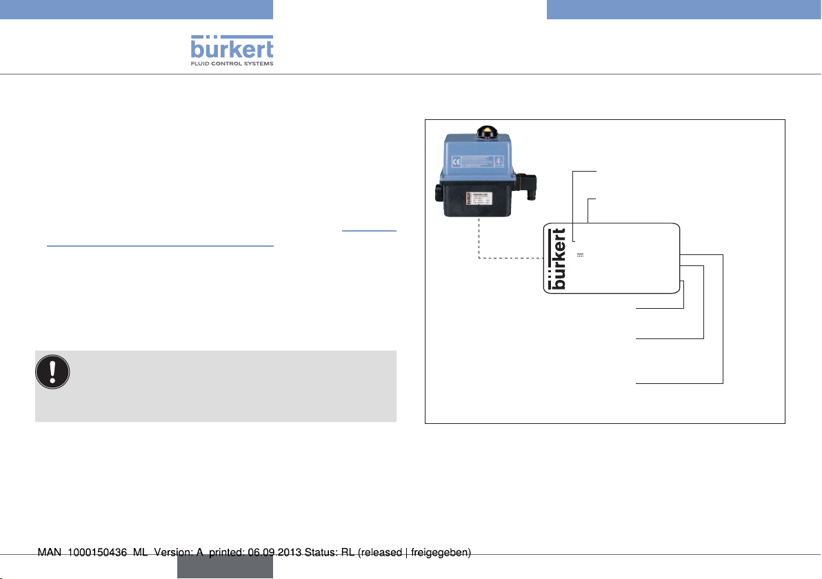
5.5. Type label
Operating voltage
Type, Identification number
3003 / 225431
~ 24 V 50/60 Hz
24 V
90° 20 Nm 15W
IP66 OF N°460050/79
Fluid Control Systems
Protection class, Serial number (internal)
Torque, Rating
Operating voltage
Fig. 1: Location and description of the type label
10/11 S46
8
english
Page 9
Type 3003
Technical Data
6. TECHNICAL DATA
6.1. Conformity
In accordance with the EC Declaration of conformity, the electromotive
rotary actuator type 3003 is compliant with the EC Directives.
6.2. Standards
The applied standards, which verify conformity with the EC Directives,
can be found on the EC Type Examination Certificate and/or the EC
Declaration of Conformity.
6.3. Operating conditions
Ambient temperature: -10 °C ... +55 °C
-10 °C ... +40 °C (Emergency
reset)
Permissible areas of application: 0 ... 2000 m altitude
Permissible humidity: < 81 % to 31 °C (88 °F) with
linear decrease as far as 50 % at
40 °C (according to EN 61010-1)
Protection class: IP66 with cable bushing
6.4. General technical data
6.4.1. Mechanical data
Dimensions: See data sheet
Weight: 1.3 kg (20 Nm)
2.8 - 3.1 kg (35-100 Nm)
Materials
Cover: Nylon
Body: PA (Nylon with glass fibre)
Axis / screws: Stainless steel
Gears: Stainless steel and PC (Polycarbonate)
Actuating angle: 90° ± 5° (optional 180°, 270°)
Duty cycle: 50 % at max. torque
6.4.2. Electrical data
Electrical connections: Cable bushing according to
EN 175301-803
Cable gland ISO M20
Limit switches: 4 adjustable (2 for the motor and 2 addi-
tional ones for feedback signal) -
max. 250 V AC / 5 A
english
9
Page 10
Type 3003
Technical Data
Electrical data for version without analog input signal:
90° Posi-
Torque
(Specifications under
load)
20 12 s 15 W 15-30 V AC, 50-60 Hz /
35 7 s 45 W 15-30 V AC, 50-60 Hz /
60 12 s 45 W 15-30 V AC, 50-60 Hz /
100 23 s 45 W 15-30 V AC, 50-60 Hz /
1)
Other positioning times on request
2)
The operating voltage must not drop below 11.5 V
tioning time1)
Power
consumption
Voltage / Frequency
12-48 V DC
2)
100-240 V AC, 50-60 Hz /
100-350 V DC
12-48 V DC
2)
100-240 V AC, 50-60 Hz /
100-350 V DC
12-48 V DC
2)
100-240 V AC, 50-60 Hz /
100-350 V DC
12-48 V DC
2)
100-240 V AC, 50-60 Hz /
100-350 V DC
Electrical data for version with analog input signal:
90° Posi-
Torque
(Specifications under
load)
20 25 s 15 W 15-30 V AC, 50-60 Hz /
35 40 s 45 W 15-30 V AC, 50-60 Hz /
60 79 s 45 W 15-30 V AC, 50-60 Hz /
100 119 s 45 W 15-30 V AC, 50-60 Hz /
1)
Other positioning times on request
2)
The operating voltage must not drop below 11.5 V
tioning time1)
Power
consumption
Voltage / Frequency
12-48 V DC
2)
100-240 V AC, 50-60 Hz /
100-350 V DC
12-48 V DC
2)
100-240 V AC, 50-60 Hz /
100-350 V DC
12-48 V DC
2)
100-240 V AC, 50-60 Hz /
100-350 V DC
12-48 V DC
2)
100-240 V AC, 50-60 Hz /
100-350 V DC
We recommend an actuator designed with 1.5 times the
maximum torque of the fitting (On/Off).
10
english
We recommend an actuator designed with 2 times the
maximum torque of the fitting (analog input signal).
Page 11
Type 3003
Technical Data
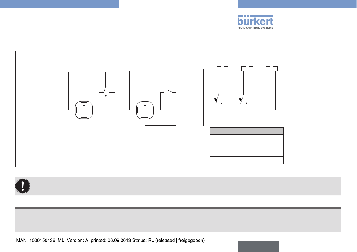
6.4.3. Electrical circuit diagrams
3-Point mode
N
-
TP/PE
1
3
2
Ph
+
Open Close
On-Off-Mode
N
-
TP/PE
1
Ph
+
Close
Open
2
3
4 5 6 7
FC1
Symbol Description
FCO Limit switch ON
FCF Limit switch OFF
FC1 Additional limit switch 1
FC2 Additional limit switch 2
Feedback
8 9
FC2
Fig. 2: Open/Closed Version
If voltage is applied simultaneously to terminals 2 and 3, terminal 2 is the leading one and the actuator moves to the OPEN position.
NOTE!
Make certain in 3-point mode that the pulse duration of a controller lasts for at least 1 second. A pause time of at least 500 ms is required
before controller activation is repeated. Observe the duty cycle specified on the type label!
Please note the circuit board must remain power supplied to allow heating resistances working.
english
11
Page 12
Type 3003
Technical Data
N
TP/PE
-
1
3
1
3
1
15V-30V 50/60 Hz (12V-48V DC)
100V-240V 50/60 Hz
(100V-350V DC)
TP/PE
17
18
17
18
P6 POSI
13 14 15 16
+ +- -
Output
signal
0-20 mA / 4-20 mA /0-10 V
Ph
+
2
2
2 3
Input
signal
D1
D2
A
B
Error feedback
(24V DC/3A max)
FCO
A B
Motor
=
Feedback
4 5 6 7
FCF
~
+
~
FC1
FC2
8 9
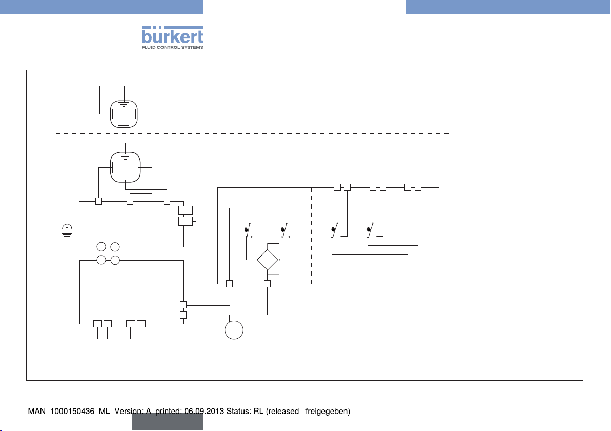
The resolution of the control mode is 1°
The input resistance for control 0-10 V is 10 kW
The input resistance for control 0-20 mA / 4-20 mA is 100 W
Fig. 3: Version with analog input signal
12
english
Page 13
Type 3003
Installation
7. INSTALLATION
7.1. Safety information
DANGER!
Hazard due to electrical voltage!
• Always switch off the power and secure it to prevent restarting
before removing the cover, or using the lever.
• Always connect multiple rotary actuators with phase isolation via
a switch!
• Protect electrical rotary actuators by using a mains-dependent
safety!
• Observe all applicable accident protection and safety guidelines
for electrical equipment!
WARNING!
Hazard due to improper installation!
• Installation may only be carried out by authorised technicians
using appropriate tools!
• Before installation, ensure that the manual lever can move freely.
Danger due to unintentional activation of the device!
Unintended actuation of the device during installation can lead to
injury and damage to property.
• Take appropriate measures to prevent the possibility of unintentional activation of the device.
7.2. Power and control connections
Procedure:
→ Disconnect the rotary actuator from the power supply.
→ Remove the position indicator from the axis.
→ Loosen the cover screws with a screwdriver and lift the cover off.
→ Disconnect the cable connector ISO20 and insert the cable.
→ Wire the connections according to the circuit diagram figures (see
“6.4.3. Electrical circuit diagrams”).
Use cables with a diameter of 7 ... 12 mm for the ISO20
cable fitting.
→ Set the cover in place and screw it tight.
→ Reinstall the position indicator.
7.3. Connecting the additional limit
switches (optional)
In the standard variant, the rotary actuator has 2 additional limit switches
(for 90º range of motion). Connect these as follows.
Procedure:
→ Disconnect the rotary actuator from the power supply.
→ Remove the position indicator from the axis.
→ Use a screwdriver to loosen the cover screws.
english
13
Page 14
Type 3003
Installation
→ Lift the cover off.
→ Wire the connections of the additional limit switches (FC1 and FC2)
according to the circuit diagram figures (see “Fig. 2” and “Fig. 3” ).
→ Tighten the cable gland after connecting the terminals.
→ Set the cover in place and screw it tight.
→ Reinstall the position indicator.
Only use 4 or 6 conductor cable with a diameter of 7 ... 12
mm for the ISO20 cable fitting.
Ensure that the cable in the ISO20 cable fitting is completely sealed when tightening the union nut.
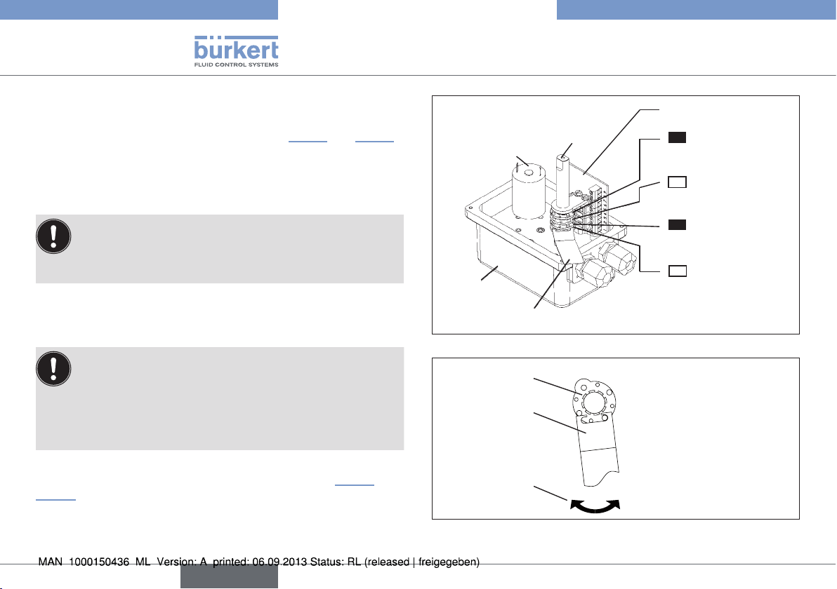
7.3.1. Setting the limit switches
The rotary actuator is supplied with the following factory
settings:
• The CLOSED limit switches are activated with the cams 2
and 4 (closed position).
• The OPEN limit switches are preset at a 90° rotation
The procedure for setting the limit switches is shown in “Fig. 4” and
“Fig. 5” .
angle.
Electronic card
Cam No. 4
Additional limit
black
switch
Cam
OPEN
Additional limit
white
switch
Cam
Motor limit switch
black
CLOSED
Cam No. 1
OPEN
Motor limit switch
OPEN
white
CLOSED
No. 3
OPEN
No. 2
Body
Motor
Wrench (00679946)
Shaft
CLOSED
CLOSED
Fig. 4: Setting the limit switches. Limit switches max. 250 V / 5 A
Cams
Wrench
Setting in
clockwise
or
setting in
clockwise
counter
direction
direction
Adjustment
direction
14
Fig. 5: Setting limit switches in counter clockwise and clockwise
directions
english
Page 15
Type 3003
Installation
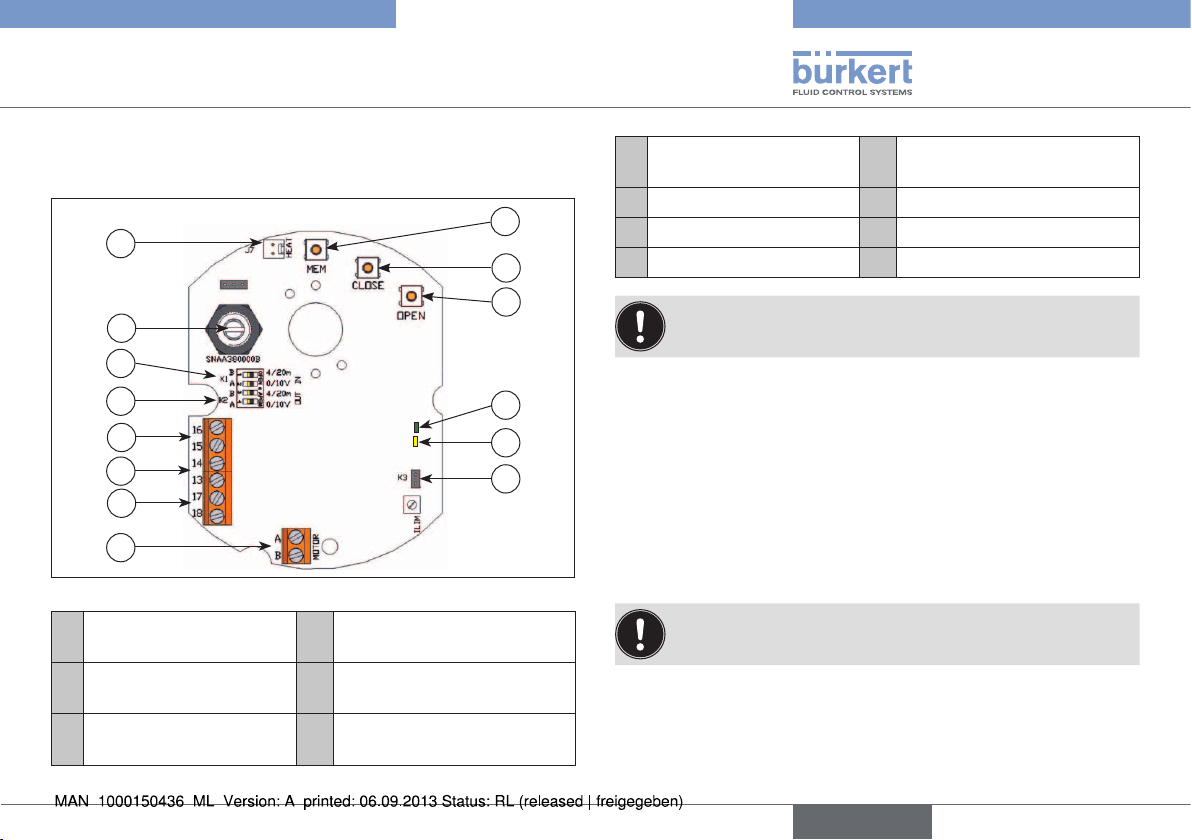
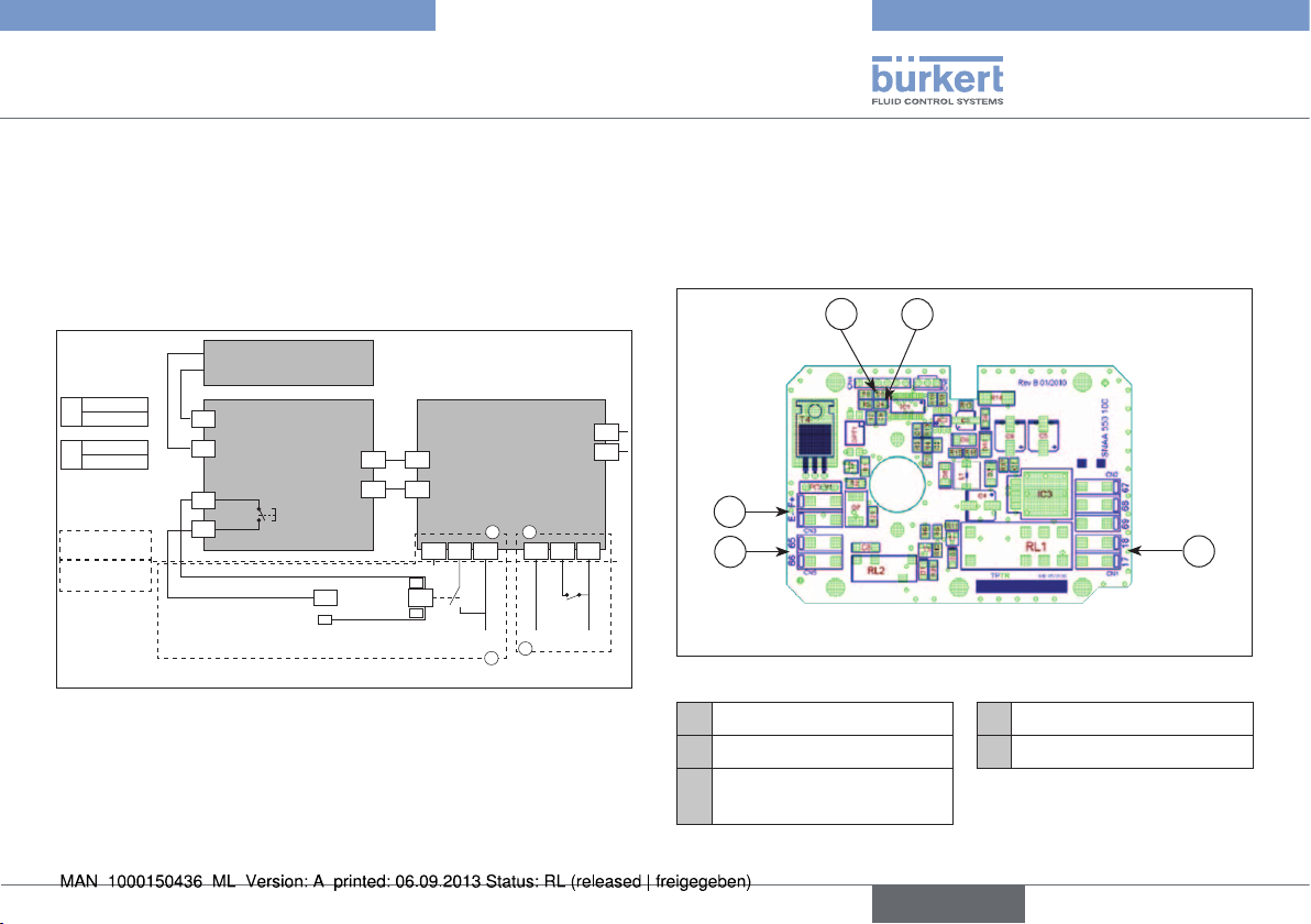
7.4. Circuit board for actuator with
standard signal input
D
N
E
F
L
G
H
B
C
A
M
Fig. 6: Circuit board
A Electrical power supply
24 V AC/DC
B Connection terminals of
the input signal
C Connection terminals of
the feedback
H K2 plug-in jumper
I K3 plug-in jumper
J Green and red LED
J
K
I
D MEM pushbutton K LED yellow: Indicates the
power supply
E CLOSE pushbutton L Potentiometer
F OPEN pushbutton M Motor connection
G K1 plug-in jumper N Heat resistor connection
To prevent electromagnetic interference, shielded cables
must be used.
Procedure:
→ Loosen the cable gland and feed the cable through.
→ Wire the signal transducer between terminals 15 and 16. Terminal
15 is the negative pole (-) and terminal 16 the positive pole (+).
→ Wire the position feedback sensor between terminals 13 and 14.
Terminal 13 is the positive pole (+) and terminal 14 the negative
pole (-).
→ Re-attach the cable gland.
If the connection voltage is 100 V to 240 V, a fuse must be
provided in the power supply.
english
15
Page 16
Type 3003
Installation
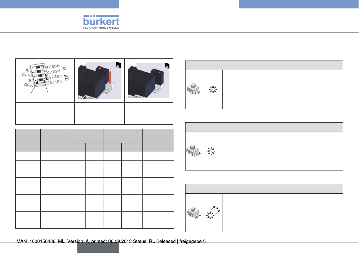
7.4.1. Specify position of the plug-in
jumpers
ONOFF
Fig. 7: Plug-in
jumper K1
/ K2
Signal
transducer
0-10 V 0-10 V ON OFF ON OFF OFF
0-10 V 0-20 mA ON OFF OFF ON OFF
0-10 V 4-20 mA ON OFF OFF ON ON
0-20 mA 0-10 V OFF ON ON OFF OFF
0-20 mA 0-20 mA OFF ON OFF ON OFF
0-20 mA 4-20 mA OFF ON OFF ON ON
4-20 mA 0-10 V OFF ON ON OFF OFF
4-20 mA 0-20 mA OFF ON OFF ON OFF
4-20 mA 4-20 mA OFF ON OFF ON ON
Feed-
back
Fig. 8: Plug-in
jumper
K3 OFF
Plug-in jumper K1Plug-in jumper K2Plug-in
A B A B
Fig. 9: Plug-in
jumper
K3 ON
jumper
K3
7.4.2. Parameterization steps
Specify direction of rotation of the shut-off valve
Normal direction of rotation (preset)
→ Press <OPEN> pushbutton and switch on
the card (hold down pushbutton).
G
The GREEN LED lights up.
→ Release <OPEN> pushbutton and disconnect
the card from the power supply.
Reverse direction of rotation
→ Press <CLOSE> pushbutton and switch on
the card (hold down pushbutton).
R
The RED LED lights up.
→ Release <CLOSE> pushbutton and disconnect
the card from the power supply.
Specify control signal type
Control signal when voltage 0 – 10 V
→ Press <MEM> pushbutton and switch on the
card (hold down pushbutton).
The RED LED lights up 3x.
R
→ Release <MEM> pushbutton and disconnect
the card from the power supply.
16
english
Page 17
Type 3003
Installation
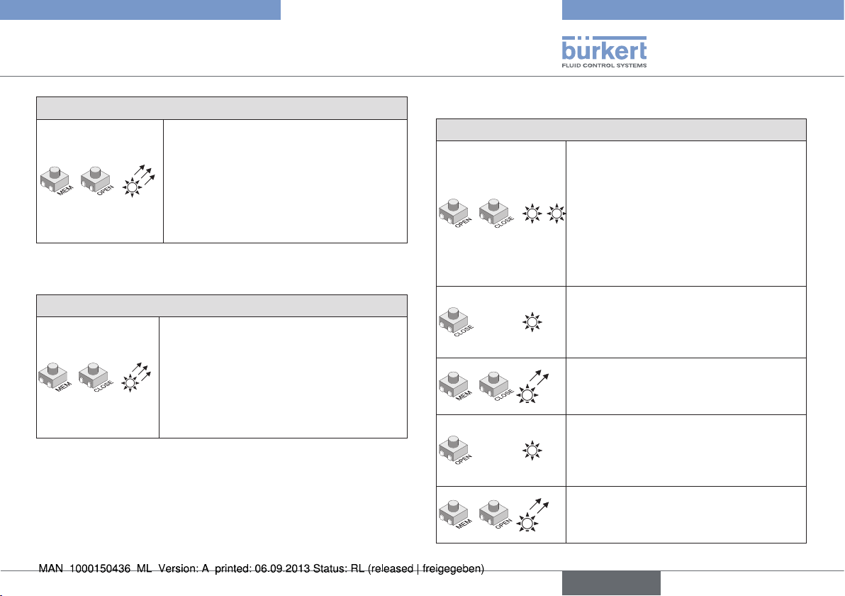
Control signal when current 0 – 20 mA
→ Press <MEM> and <OPEN> push-
button and switch on the card (hold
down pushbutton).
The RED LED lights up 3x.
R
→ Release <MEM> and <OPEN> push-
button and disconnect the card from
the power supply.
Control signal when current 4 – 20 mA (preset)
→ Press <MEM> and <CLOSE> push-
button and switch on the card (hold
down pushbutton).
The RED LED lights up 3x.
R
→ Release <MEM> and <CLOSE>
pushbutton and disconnect the card
from the power supply.
Learning mode
Specify end positions
G R
R
R
G
R
→ Press <OPEN> and <CLOSE>
pushbutton and switch on the card
(hold down pushbutton).
The RED and the GREEN LEDs light up.
→ Release <OPEN> and <CLOSE>
pushbutton.
Both LEDs go out.
Learning mode is selected.
→ Press <CLOSE> pushbutton to move
the shut-off valve into the closed
position.
The RED LED lights up.
→ Press <MEM> and <CLOSE> push-
button to save the closed position.
The RED LED lights up 2x.
→ Press <OPEN> pushbutton to move
the shut-off valve into the open
position.
The GREEN LED lights up.
→ Press <MEM> and <OPEN> push-
button to save the open position.
The GREEN LED lights up 2x.
english
17
Page 18
Type 3003
Rotary actuators with integrated emergency reset
Specify end positions
All positions are now saved.
→ Disconnect the card from the power
supply.
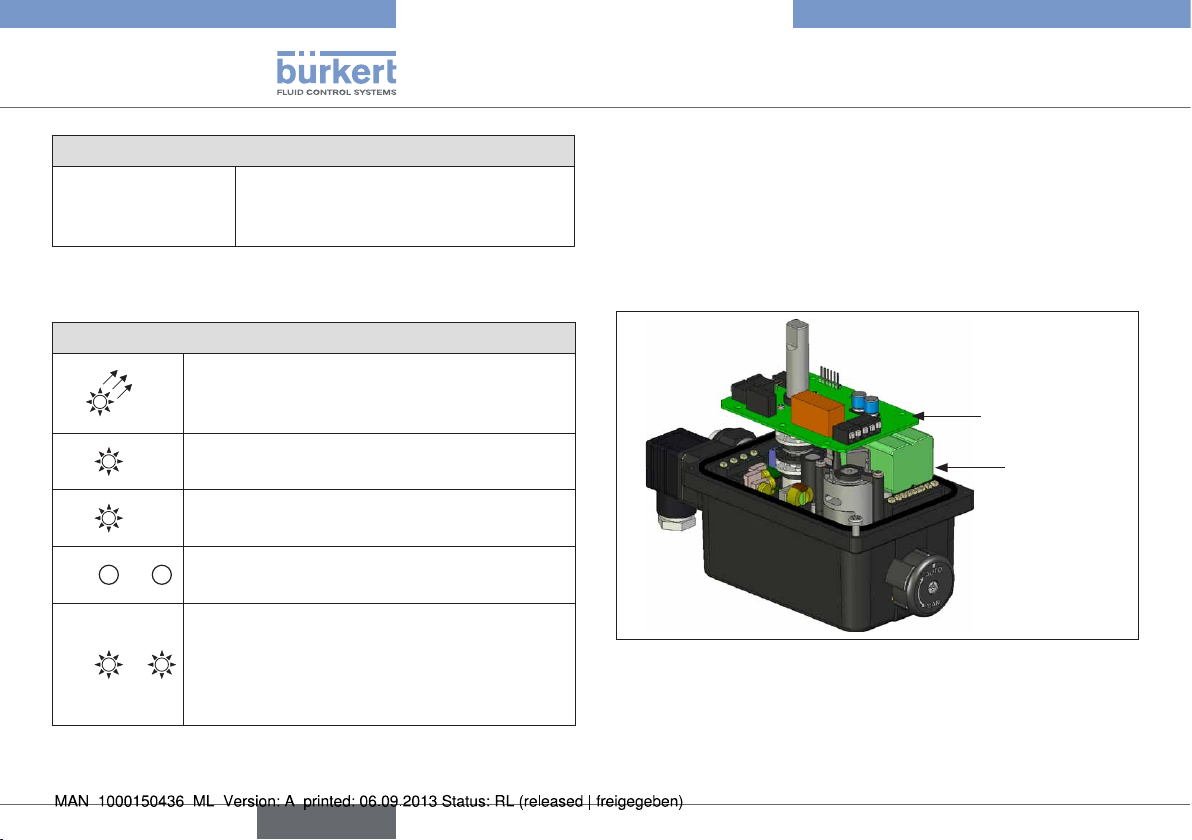
7.4.3. Normal operation
Display normal operation
→ Switch on card.
G
G
R
G
G R
The GREEN LED lights up 3x to indicate that the
start process has been implemented correctly.
In normal operation the GREEN LED lights up
when the rotary actuator opens the shut-off valve.
The RED LED lights up when the rotary actuator
closes the shut-off valve.
If neither of the LEDs is lit, the actuator is not
R
actuated.
The RED and the GREEN LEDs light up if the
torque is too high and the rotary actuator stops.
→ Change direction of rotation of the rotary
actuator or switch over the voltage OPEN/
CLOSED to restart the rotary actuator!
8. ROTARY ACTUATORS WITH
INTEGRATED EMERGENCY
RESET
8.1. Safety block for emergency
power version
Circuit board
Battery
Fig. 10: Safety block for emergency power version
8.2. Technical data
Voltage: 18 V DC
Currant nominal: 0.8 A
18
english
Page 19
Type 3003
Rotary actuators with integrated emergency reset
Max. current 2.4 A
Charging time 14 h max
Feedback relay for charge state 24 V DC - 1 A max
Permitted ambient temperature -10 °C - +40 °C
8.3. Electric wiring
Battery block
Wire colour
F+
red
Wire colour
E-
black
Load state
feedback
Actuator
wiring
Suggestet customer
wiring
KM1 - Customer
switch
contactor
On / Off Mode
F+
E-
65
66
Safety block
Loaded battery: closed
contact
24 V
DC
AC/
N
Total security mode
17
18
Fig. 11: Electric wiring
Configuration A or B
A-standard mode: If the actuator is controlled with a programmable
controller, the feedback of the charge state can be connected to it.
Control and power
supply card
17
100V-240V 50/60 Hz
(100V-350V DC)
18
15V-30V 50/60 Hz
(12V-48V DC)
A
B
1 2 3 1 2 3
N
A1
Open
KM1
A2
Ph
A
B
D1
D2
Open
N
Ph
B-mode - increased safety (if the feedback relay is used, terminals
65 and 66): The actuator does not actuate the valve unless the safety
block is loaded.
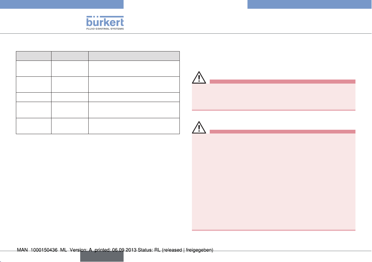
8.4. Circuit board
D
B
C
Fig. 12: Diagram: Circuit board
A 18 V DC connection D Green LED*
B Battery block connection E Red LED **
C Connection for feedback
(charge state)
E
A
english
19
Page 20
Type 3003
Operating
Description of the LED:
Green LED Red LED Description
Off Blinks / Off /
Blinks
On Blinks Battery loading cycle in progress
On Off Battery loading cycle finished
Blinks
rapidly
Off Blinks
Off Actuator electrical supply during
rapidly
Battery off or out of service
(max. 14 h)
3 min. (failure mode)
Microcontroller failure
9. OPERATING
9.1. Safety information
DANGER!
Hazard due to electrical voltage!
Intervention in the device poses an acute risk of injury.
• Turn off the power before manually servicing the rotary actuator.
WARNING!
Hazard due to improper servicing!
Improper servicing can result in personal injury and in damage to
the device and its surroundings.
• The operating personnel must be aware of and fully understand
the operating instructions.
• Pay attention in particular to the safety information and the
intended use.
• The device may only be serviced by properly trained personnel.
Hazardous situation due to manual intervention!
During manual intervention the process can change into an undefined state which can lead to hazardous situations.
• Ensure a defined and controlled restarting of the process following manual intervention!
20
english
Page 21
Type 3003
Operating
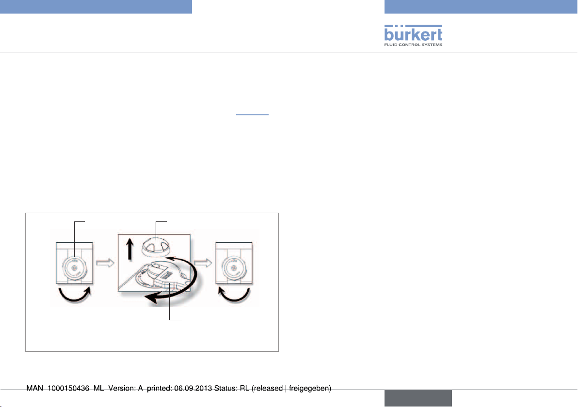
9.2. Manual operation of the rotary
actuator
The rotary actuator can be operated manually if there is a power failure.
To do this, the handwheel must be turned to „MAN“ (see “Fig. 13” ).
Procedure:
→ During manual operation ensure that the rotary actuator is not
activated in automatic mode.
→ Remove the position indicator from the axle.
→ Turn the handwheel from “AUTO” to “MAN”.
→ Using a wrench, turn the actuator shaft into the required position.
In doing so, hold the handwheel.
Handwheel
For manual operation
turn the mark
downwards
Position indicator
Wrench
9.3. Returning from manual to
automatic operation
Returning to automatic operation:
→ Let go off the handwheel to switch back into automatic operation.
The spring force automatically resets it to the „AUTO“ position.
→ Replace the position indicator.
The marking should now show the set position.
Fig. 13: Switching the rotary actuator from automatic to manual
operation
english
21
Page 22

Type 3003
Maintenance and repair
10. MAINTENANCE AND REPAIR
10.1. Safety information
WARNING!
Hazard due to improper maintenance!
• Installation and maintenance work may only be carried out by
authorised technicians using appropriate tools!
Danger due to unintentional activation of the system!
Unintended actuation of the system during maintenance and repair
work can lead to injury and damage to property.
• Take appropriate measures to prevent the possibility of unintentional activation of the system.
10.2. Maintenance
The rotary actuator is maintenance-free when used in a manner corresponding to the instructions in this manual.
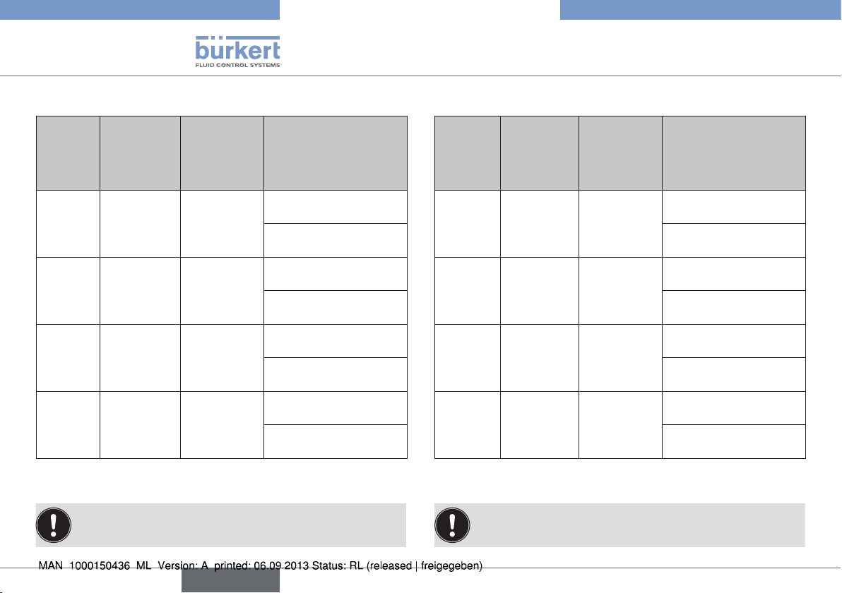
10.3. Malfunctions
Malfunctions Resolution
The rotary actuator
does not function (first
commissioning)
Check power supply
Check the connections against the
circuit diagram included
Malfunctions Resolution
The rotary actuator is stuck
in the OPEN position
The valve does not open
or close
completely
The rotary actuator is stuck
in the CLOSED position
Check power supply
Check the connections against the
circuit diagram included
Check whether the movement of the
electrical valve is obstructed
Check power supply
Check the connections against the
circuit diagram included
Check the limit switches
Check whether there is any overload
due to too-high torque on the valve
(our rotary actuators are equipped
with thermostats)
If yes: interrupt power for 5 minutes
Check power supply
Check the connections against the
circuit diagram included
Check whether the movement of the
electrical valve is obstructed
22
english
Page 23

Type 3003
Accessories
11. ACCESSORIES
CAUTION!
Risk of injury and/or damage by the use of incorrect parts!
Incorrect accessories and unsuitable replacement parts may cause
injuries and damage the device and the surrounding area.
• Use only original accessories and original spare parts supplied
by Bürkert.
Designation Order no.
Key for adjusting the limit switches 679 946
Reducing sleeve star/square 14/9 mm 665 288
Reducing sleeve star/square 14/11 mm 665 289
Reducing sleeve star/star 22/14 mm 666 684
Reducing sleeve star/square 22/17 mm 684 858
Reducing sleeve square/square 17/14 mm 665 290
Adapter outer square 14/10 mm 668 234
Position indicator 20 Nm 679 722
Position indicator > 20 Nm 679 723
12. TRANSPORT, STORAGE,
DISPOSAL
NOTE!
Transport damages!
Inadequately protected equipment may be damaged during transport.
• During transportation protect the device against wet and dirt in
shock-resistant packaging.
• Avoid exceeding or dropping below the permitted storage
temperature.
Incorrect storage may damage the device.
• Store the device in a dry and dust-free location!
• Storage temperature. -10 … +55 °C.
Damage to the environment caused by device components
contaminated with media.
• Dispose of the device and packaging in an environmentally
friendly manner.
• Observe applicable regulations on disposal and the
environment.
• Observe national waste disposal regulations.
23
english
Page 24

Type 3003
Accessories
24
english
Page 25

Typ 3003
Inhaltsverzeichnis
1. DIE BEDIENUNGSANLEITUNG ............................................................26
1.1. Darstellungsmittel ...........................................................................26
1.2. Begriffsdefinition Gerät .................................................................26
2. BESTIMMUNGSGEMÄSSE VERWENDUNG ...................................27
2.1. Beschränkungen ............................................................................27
3. GRUNDLEGENDE SICHERHEITSHINWEISE ................................. 27
4. ALLGEMEINE HINWEISE .......................................................................... 29
4.1. Kontaktadressen .............................................................................29
4.2. Gewährleistung...............................................................................29
4.3. Informationen im Internet ..............................................................29
5. SYSTEMBESCHREIBUNG ....................................................................... 29
5.1. Vorgesehener Einsatzbereich ......................................................29
5.2. Allgemeine Beschreibung ............................................................29
5.3. Optionen ..........................................................................................30
5.4. Kennzeichnung................................................................................30
5.5. Typschild ..........................................................................................30
6. TECHNISCHE DATEN ................................................................................ 31
6.1. Konformität .......................................................................................31
6.2. Normen .............................................................................................31
6.3. Zulassungen ....................................................................................31
6.4. Betriebsbedingungen ....................................................................31
6.5. Allgemeine technische Daten ......................................................31
7.2. Strom- und Steueranschlüsse ....................................................35
7.3. Anschluss der zusätzlichen Endschalter (optional) ................35
7.4. Platine für Antrieb mit Normsignaleingang ...............................37
8. DREHANTRIEBE MIT INTEGRIERTER
NOTRÜCKSTELLUNG ................................................................................ 40
8.1. Sicherheitsblock für Notstromvariante ......................................40
8.2. Technische Daten...........................................................................40
8.3. Anschluss-Schema ........................................................................41
8.4. Platine ...............................................................................................41
9. BEDIENUNG ...................................................................................................42
9.1. Sicherheitshinweise .......................................................................42
9.2. Manuelle Bedienung des Drehantriebs .....................................43
9.3. Rückkehr vom manuellen in den Automatikbetrieb ................43
10. WARTUNG, FEHLERBEHEBUNG....................................................... 44
10.1. Sicherheitshinweise.....................................................................44
10.2. Wartungsarbeiten ........................................................................44
10.3. Störungen ......................................................................................44
11. ZUBEHÖR ...................................................................................................... 45
12. TRANSPORT, LAGERUNG, ENTSORGUNG ................................. 45
7. MONTAGE ........................................................................................................35
7.1. Sicherheitshinweise .......................................................................35
deutsch
25
Page 26

Typ 3003
Die Bedienungsanleitung
1. DIE BEDIENUNGSANLEITUNG
Die Bedienungsanleitung beschreibt den gesamten Lebenszyklus
des Geräts. Bewahren Sie diese Anleitung so auf, dass sie für jeden
Benutzer gut zugänglich ist und jedem neuen Eigentümer des Geräts
wieder zur Verfügung steht.
Die Bedienungsanleitung enthält wichtige Informationen zur
Sicherheit!
Das Nichtbeachten dieser Hinweise kann zu gefährlichen Situationen
führen.
• Die Bedienungsanleitung muss gelesen und verstanden werden.
1.1. Darstellungsmittel
GEFAHR!
Warnt vor einer unmittelbaren Gefahr!
• Bei Nichtbeachtung sind Tod oder schwere Verletzungen die
Folge.
WARNUNG!
Warnt vor einer möglicherweise gefährlichen Situation!
• Bei Nichtbeachtung drohen schwere Verletzungen oder Tod.
VORSICHT!
Warnt vor einer möglichen Gefährdung!
• Nichtbeachtung kann mittelschwere oder leichte Verletzungen
zur Folge haben.
HINWEIS!
Warnt vor Sachschäden!
• Bei Nichtbeachtung kann das Gerät oder die Anlage beschädigt
werden.
Bezeichnet wichtige Zusatzinformationen, Tipps und
Empfehlungen.
Verweist auf Informationen in dieser Bedienungsanleitung
oder in anderen Dokumentationen.
→ markiert einen Arbeitsschritt, den Sie ausführen müssen.
1.2. Begriffsdefinition Gerät
Der in dieser Anleitung verwendeten Begriff „Gerät“ steht immer für
den elektromotorischen Drehantrieb Typ 3003.
26
deutsch
Page 27

Typ 3003
Bestimmungsgemäße Verwendung
2. BESTIMMUNGSGEMÄSSE
VERWENDUNG
Bei nicht bestimmungsgemäßem Einsatz des elektromotorischen Drehantriebs Typ 3003 können Gefahren für Personen,
Anlagen in der Umgebung und die Umwelt entstehen.
• Der elektromotorische Drehantrieb darf im Außenbereich eingesetzt werden.
• Für den Einsatz die in den Vertragsdokumenten und der Bedienungsanleitung spezifizierten zulässigen Daten, Betriebs- und
Einsatzbedingungen beachten. Diese sind im Kapitel „Technische
Daten“ beschrieben.
• Das Gerät nur in Verbindung mit von Bürkert empfohlenen bzw.
zugelassenen Fremdgeräten und -komponenten einsetzen.
• Voraussetzungen für den sicheren und einwandfreien Betrieb sind
sachgemäßer Transport, sachgemäße Lagerung und Installation
sowie sorgfältige Bedienung und Instandhaltung.
• Das Gerät nur bestimmungsgemäß einsetzen.
2.1. Beschränkungen
Beachten Sie bei der Ausfuhr des Systems/Gerätes gegebenenfalls
bestehende Beschränkungen.
3. GRUNDLEGENDE
SICHERHEITSHINWEISE
Diese Sicherheitshinweise berücksichtigen keine
• Zufälligkeiten und Ereignisse, die bei Montage, Betrieb und Wartung
der Geräte auftreten können.
• ortsbezogenen Sicherheitsbestimmungen, für deren Einhaltung, auch
in Bezug auf das Montagepersonal, der Betreiber verantwortlich ist.
Gefahr durch elektrische Spannung!
• Vor Eingriffen in das Gerät oder die Anlage, Spannung abschalten und vor Wiedereinschalten sichern!
• Mehrere elektromotorische Drehantriebe AUF/ZU immer
mit Phasentrennung über einen Schalter anschließen.
• Das Gerät durch eine netzabhängige Sicherung schützen.
• Die geltenden Unfallverhütungs- und Sicherheitsbestimmungen
für elektrische Geräte beachten!
Unbeabsichtigtes Betätigen oder unzulässige Beeinträchtigung
können zu allgemeinen Gefahrensituationen bis hin zur Körperverletzung führen!
• Durch geeignete Maßnahmen verhindern, dass das Gerät unbeabsichtigt betätigt werden kann!
Für die Einsatzplanung und den Betrieb des Geräts gelten die
allgemeinen Regeln der Technik!
• Die allgemeinen Regeln der Technik einhalten!
deutsch
27
Page 28

Typ 3003
Grundlegende Sicherheitshinweise
Allgemeine Gefahrensituationen.
Zum Schutz vor Verletzungen/Sachschaden beachten:
• Der elektromotorische Drehantrieb AUF/ZU Typ 3003 darf nicht
in explosionsgefährdeten Bereichen eingesetzt werden (in diesem
Fall Typ 3004 verwenden).
• Das Gehäuse nicht mechanisch belasten (z. B. durch Ablage von
Gegenständen oder als Trittstufe).
• Keine äußerlichen Veränderungen an den Gerätegehäusen vornehmen. Gehäuseteile und Schrauben nicht lackieren.
• Antrieb nicht mit dem Deckel nach unten (kopfüber) einbauen.
• Bei der Montage des Antriebs einen Mindestabstand von 30 cm
zu elektromagnetischen Störquellen berücksichtigen.
• Nur geschultes Fachpersonal darf Installations- und Instandhaltungsarbeiten ausführen.
• Nach einer Unterbrechung der elektrischen oder pneumatischen
Versorgung für einen definierten oder kontrollierter Wiederanlauf
des Prozesses sorgen.
• Das Gerät nur in einwandfreiem Zustand und unter Beachtung
der Bedienungsanleitung betreiben.
• Für die Einsatzplanung und den Betrieb des Gerätes die allgemeinen Regeln der Technik einhalten.
HINWEIS!
Elektrostatisch gefährdete Bauelemente / Baugruppen!
Das Gerät enthält elektronische Bauelemente, die gegen elektrostatische Entladung (ESD) empfindlich reagieren. Berührung mit elektrostatisch aufgeladenen Personen oder Gegenständen gefährdet
diese Bauelemente. Im schlimmsten Fall werden sie sofort zerstört
oder fallen nach der Inbetriebnahme aus.
• Beachten Sie die Anforderungen nach EN 61340-5-1, um die
Möglichkeit eines Schadens durch schlagartige elektrostatische
Entladung zu minimieren bzw. zu vermeiden!
• Achten Sie ebenso darauf, dass Sie elektronische Bauelemente
nicht bei anliegender Betriebsspannung berühren!
28
deutsch
Page 29

Typ 3003
Allgemeine Hinweise
4. ALLGEMEINE HINWEISE
4.1. Kontaktadressen
Deutschland
Bürkert Fluid Control Systems
Sales Center
Christian-Bürkert-Str. 13-17
D-74653 Ingelfingen
Tel. + 49 (0) 7940 - 10 91 111
Fax + 49 (0) 7940 - 10 91 448
E-mail: info@de.buerkert.com
International
Die Kontaktadressen finden Sie auf den letzten Seiten der gedruckten
Bedienungsanleitung.
Außerdem im Internet unter: www.burkert.com
4.2. Gewährleistung
Voraussetzung für die Gewährleistung ist der bestimmungsgemäße
Gebrauch des elektromotorischen Drehantriebs Typ 3003 unter
Beachtung der spezifizierten Einsatzbedingungen.
4.3. Informationen im Internet
Bedienungsanleitungen und Datenblätter zum Typ 3003 finden Sie im
Internet unter: www.buerkert.de
5. SYSTEMBESCHREIBUNG
5.1. Vorgesehener Einsatzbereich
Der elektromotorische Drehantrieb AUF/ZU Typ 3003 (im Folgenden
als Drehantrieb bezeichnet) ist für Kugelhahn- oder Klappenventile
konzipiert.
5.2. Allgemeine Beschreibung
Das Basisgerät kann durch die modulare Konstruktion mit vielen
Optionen erweitert werden.
Optionen zur Erweiterung des Basisgerätes finden Sie im
Kapitel „5.3. Optionen“.
Der Drehantrieb ist für Gleich- oder Wechselstrom mit unterschiedlicher Leistung konzipiert und für Drehmomente von 20, 35, 60 oder
100 Nm lieferbar.
Die verwendeten Werkstoffe gewährleisten einen wartungsfreien
Betrieb und stellen eine niedrige thermische Belastung sicher.
Alle Drehantriebe sind in der Standardausführung mit einer Handnotbetätigung und zwei zusätzlichen Endschaltern ausgestattet und vom
Hersteller getestet. Die Endschalter wurden auf 0 ... 90° Schwenkbetrieb eingestellt. Nachstellen ist nicht notwendig.
deutsch
29
Page 30

Typ 3003
Systembeschreibung
5.3. Optionen
• Zusätzliche Endschalter
• Drehantrieb mit Rückmelde - Potentiometer:
- Potentiometer mit Widerstandswerten von: 100
W, 1 kW, 5 kW,
10 kW
- Analoge Rückmeldung über 4 ... 20 mA-Signal
• Dreistellungsdrehantrieb (180°)
• Drehantriebe mit integrierter Notrückstellung (siehe auch Kapitel
„8. Drehantriebe mit integrierter Notrückstellung“)
5.4. Kennzeichnung
Der Drehantrieb ist mit einem Typschild versehen, das eine eindeutige
Identifikation ermöglicht und die wichtigsten technischen Daten
erkennen lässt.
Das Typschild nicht vom Drehantrieb entfernen!
Es ist für die Identifikation bei Installation und Instandhaltung
von entscheidender Bedeutung.
Ohne Typschild erlischt die Gewährleistung.
5.5. Typschild
Betriebsspannung
Typbezeichnung, Identnummer
3003 / 225431
~ 24 V 50/60 Hz
24 V
90° 20 Nm 15W
IP66 OF N°460050/79
Fluid Control Systems
Schutzart, Seriennummer (intern)
Drehmoment, Leistung
Betriebsspannung
Bild 1: Lage und Beschreibung des Typschildes
10/11 S46
30
deutsch
Page 31

Typ 3003
Technische Daten
6. TECHNISCHE DATEN
6.1. Konformität
Der elektromotorische Drehantrieb Typ 3003 ist konform zu den EGRichtlinien entsprechend der Konformitätserklärung.
6.2. Normen
Die angewandten Normen, mit denen die Konformität mit den EG-Richtlinien nachgewiesen wird, sind in der EG-Baumusterprüfbescheinigung
und/oder der EG-Konformitätserklärung nachzulesen.
6.3. Betriebsbedingungen
Umgebungstemperatur: -10 °C ... +55 °C
-10 °C ... +40 °C (Notrückstellung)
Zulässiger Einsatzbereich: 0 ... 2000 m Höhe
Zulässige Luftfeuchtigkeit: < 81 % bis 31 °C (88 °F) mit linearer
Abnahme bis zu 50 % bei 40 °C
(gemäß EN 61010-1)
Schutzart: IP66 mit Gerätesteckdose
6.4. Allgemeine technische Daten
6.4.1. Mechanische Daten
Abmessungen: Siehe Datenblatt
Masse: 1,3 kg (20 Nm)
2,8 - 3,1 kg (35-100 Nm)
Werkstoffe
Deckel: Nylon
Gehäuse: PA (Nylon, glasfaserverstärkt)
Achse/Schrauben: Edelstahl
Getriebe: Edelstahl und PC (Polycarbonat)
Stellwinkel: 90° ± 5° (optional 180°, 270°)
Einschaltdauer: 50 % bei maximalem Drehmoment
6.4.2. Elektrische Daten
Elektrische Anschlüsse: Gerätesteckdose nach EN 175301-803
Kabelverschraubung ISO M20
Endschalter: 4 einstellbar (2 für den Motor und
2 zusätzliche für Rückmeldesignal) -
max. 250 V AC / 5 A
deutsch
31
Page 32

Typ 3003
Technische Daten
Elektrische Daten für Ausführung ohne Analogeingangssignal:
Dreh-
moment
20 12 s 15 W 15-30 V AC, 50-60 Hz /
35 7 s 45 W 15-30 V AC, 50-60 Hz /
60 12 s 45 W 15-30 V AC, 50-60 Hz /
100 23 s 45 W 15-30 V AC, 50-60 Hz /
1)
Andere Stellzeiten auf Anfrage
2)
Die Betriebsspannung darf 11,5 V nicht unterschreiten
90°
Stellzeit 1)
(Angaben
unter Last)
Leistungsauf-
nahme
Spannung / Frequenz
12-48 V DC
2)
100-240 V AC, 50-60 Hz /
100-350 V DC
12-48 V DC
2)
100-240 V AC, 50-60 Hz /
100-350 V DC
12-48 V DC
2)
100-240 V AC, 50-60 Hz /
100-350 V DC
12-48 V DC
2)
100-240 V AC, 50-60 Hz /
100-350 V DC
Elektrische Daten für Ausführung mit Analogeingangssignal:
Dreh-
moment
20 25 s 15 W 15-30 V AC, 50-60 Hz /
35 40 s 45 W 15-30 V AC, 50-60 Hz /
60 79 s 45 W 15-30 V AC, 50-60 Hz /
100 119 s 45 W 15-30 V AC, 50-60 Hz /
1)
Andere Stellzeiten auf Anfrage
2)
Die Betriebsspannung darf 11,5 V nicht unterschreiten
90°
Stellzeit 1)
(Angaben
unter Last)
Leistungsauf-
nahme
Spannung / Frequenz
12-48 V DC
2)
100-240 V AC, 50-60 Hz /
100-350 V DC
12-48 V DC
2)
100-240 V AC, 50-60 Hz /
100-350 V DC
12-48 V DC
2)
100-240 V AC, 50-60 Hz /
100-350 V DC
12-48 V DC
2)
100-240 V AC, 50-60 Hz /
100-350 V DC
Wir empfehlen eine Antriebsauslegung mit dem 1,5-fachen
des maximalen Drehmoments der Armatur (On/Off).
32
Wir empfehlen eine Antriebsauslegung mit dem 2-fachen des
maximalen Drehmoments der Armatur (Analogeingangssignal).
deutsch
Page 33

Typ 3003
Technische Daten
6.4.3. Elektrische Schaltschemen
3-Punkt Modus
N
-
TP/PE
2
1
3
Ph
+
Auf Zu
Auf/Zu Modus
N
-
TP/PE
1
3
Ph
+
Zu
Auf
2
FC1
Symbol Bedeutung
Rückmeldung
4 5 6 7
FC2
FCO Endschalter AUF
FCF Endschalter ZU
FC1 Zusätzlicher Endschalter 1
FC2 Zusätzlicher Endschalter 2
8 9
Bild 2: Auf/Zu Ausführung
Sind die Klemmen 2 und 3 gleichzeitig mit Spannung beaufschlagt, ist die Klemme 2 die führende und der Antrieb fährt in Position AUF.
HINWEIS!
Beim 3-Punkt Modus ist darauf zu achten, dass die Impulsdauer einer Ansteuerung mindestens 1 s beträgt. Vor einer erneuten Ansteuerung
ist eine Pausenzeit von mindestens 500 ms notwendig. Die auf dem Typenschild angegebene Einschaltdauer ist zu beachten!
Bitte darauf achten, dass die Platine mit Strom versorgt bleibt, sodass die Heizwiderstände in Betrieb bleiben.
deutsch
33
Page 34

Typ 3003
Technische Daten
N
TP/PE
-
1
3
1
3
1
15V-30V 50/60 Hz (12V-48V DC)
100V-240V 50/60 Hz
(100V-350V DC)
TP/PE
17
18
17
18
P6 POSI
13 14 15 16
+ +- -
Ausgangs-
0-20 mA / 4-20 mA /0-10 V
signal
Eingangs-
Ph
+
2
2
2 3
signal
D1
D2
Rückmeldung
4 5 6 7
FCO
Fehlerrückmeldung
(24V DC/3A max)
A B
A
B
Motor
=
FCF
~
+
~
Die Auflösung des Regelbetriebs beträgt 1°
Der Eingangswiderstand bei Ansteuerung 0-10 V beträgt 10 kW
FC1
FC2
8 9
Der Eingangswiderstand bei Ansteuerung 0-20 mA / 4-20 mA beträgt 100 W
Bild 3: Ausführung mit Analogsignaleingang
34
deutsch
Page 35

Typ 3003
Montage
7. MONTAGE
7.1. Sicherheitshinweise
GEFAHR!
Gefahr durch elektrische Spannung!
• Vor Eingriffen in das Gerät oder die Anlage, Spannung abschalten und vor Wiedereinschalten sichern.
• Mehrere Drehantriebe immer mit Phasentrennung über
einen Schalter anschließen!
• Drehantriebe durch eine netzabhängige Sicherung schützen!
• Die geltenden Unfallverhütungs- und Sicherheitsbestimmungen
für elektrische Geräte beachten!
WARNUNG!
Verletzungsgefahr bei unsachgemäßer Montage!
• Die Montage darf nur autorisiertes Fachpersonal mit geeignetem Werkzeug durchführen!
• Vor der Installation darauf achten, dass sich der Handhebel frei
bewegen kann.
Gefahr durch unbeabsichtigte Betätigung des Gerätes!
Ungewolltes Ingangsetzen des Gerätes bei der Montage kann zu
Verletzungen und Sachschäden führen.
• Durch geeignete Maßnahmen verhindern, dass das Gerät nicht
unbeabsichtigt betätigt werden kann.
7.2. Strom- und Steueranschlüsse
Vorgehensweise:
→ Drehantrieb von der Spannungsversorgung trennen.
→ Stellungsanzeige von der Achse abziehen.
→ Verschraubungen des Deckels mit einem Schraubendreher lösen.
→ Deckel abheben.
→ Kabelverschraubung ISO20 lösen und die Anschlussleitungen
einführen.
→ Die Anschlüsse entsprechend der Schaltschemen verdrahten
(siehe „6.4.3. Elektrische Schaltschemen“).
Für die Kabelverschraubung ISO20, Kabel mit einem Durchmesser von 7 ... 12 mm verwenden.
→ Deckel aufsetzen und festschrauben.
→ Stellungsanzeige wieder anbringen.
7.3. Anschluss der zusätzlichen
Endschalter (optional)
In der Standardausführung haben die Drehantriebe zwei zusätzliche
Endschalter (für 90° Schwenkeinstellung).
Vorgehensweise:
→ Drehantrieb von der Spannungsversorgung trennen.
→ Stellungsanzeige von der Achse abziehen.
deutsch
35
Page 36

Typ 3003
Montage
→ Verschraubungen des Deckels mit einem Schraubendreher lösen.
→ Deckel abheben.
→ Anschlüsse der zusätzlichen Endschalter (FC1 und FC2) gemäß
der Schaltschemen verdrahten (siehe „Bild 2“ und „Bild 3“ ).
→ Die Klemmen anschließen und Kabelverschraubung anziehen.
→ Deckel aufsetzen und festschrauben.
→ Stellungsanzeige wieder anbringen.
Nur 4- bzw. 6-adriges Kabel mit einem Durchmesser von
7 ... 12 mm für die ISO20 Kabelverschraubung verwenden.
Beachten, dass beim Verschrauben der Überwurfmutter das
Kabel an der ISO20 Kabelverschraubung abgedichtet ist.
7.3.1. Einstellen der Endschalter
Der Drehantrieb wird ab Werk mit folgenden Einstellungen
geliefert:
• Die Endschalter ZU sind durch die Nocken 2 und 4
betätigt (geschlossene Position).
• Die Endschalter AUF sind auf einen Drehwinkel von 90°
Die Vorgehensweise beim Einstellen der Endschalter ist im „Bild 4“
und „Bild 5“ dargestellt.
voreingestellt.
Elektronische Karte
Nocke Nr. 4
Motor
Welle
Gehäuse
Schlüssel (00679946)
ZU
schwarz
AUF
weiss
ZU
schwarz
AUF
weiss
Zusätzlicher
Endschalter ZU
Nr. 3
Nocke
Zusätzlicher
Endschalter AUF
Nocke Nr. 2
Motor-
Endschalter ZU
Nr. 1
Nocke
Motor-
Endschalter AUF
Bild 4: Einstellen der Endschalter. Endschalter max. 250 V / 5 A
Nocken
Einstellung im
oder gegen den
Schlüssel
Uhrzeigersinn
Stellweg
36
Bild 5: Endschaltereinstellung im und gegen den Uhrzeigersinn
deutsch
Page 37

Typ 3003
Montage
7.4. Platine für Antrieb mit
Normsignaleingang
N
L
G
H
B
C
A
M
Bild 6: Platine
A Spannungsversorgung
24 V AC/DC
B Anschlussklemmen des
Eingangssignals
C Anschlussklemmen der
Rückmeldung
H K2 Steckbrücke
I K3 Steckbrücke
J Grüne und rote LED
D Taster MEM K LED gelb: Anzeige der
Stromversorgung
D
E
F
J
K
I
E Taster CLOSE L Potentiometer
F Taster OPEN M Motoranschluss
G K1 Steckbrücke N Heizwiderstandsverbindung
Um elektromagnetische Störungen zu vermeiden müssen
abgeschirmte Kabel benutzt werden.
Vorgehensweise:
→ Kabelverschraubung lösen und das Kabel durchführen.
→ Signalgeber zwischen den Klemmen 15 und 16 verkabeln. Die
Klemme 15 ist negativ gepolt (-) und die Klemme 16 positiv (+).
→ Positionsrückmelder zwischen Klemmen 13 und 14 verkabeln.
Die Klemme 13 ist positiv gepolt (+) und die Klemme 14 negativ
(-).
→ Die Kabelverschraubung wieder befestigen.
Beträgt die Anschlussspannung 100 V bis 240 V muss eine
Sicherung in der Stromzufuhr vorgesehen werden.
deutsch
37
Page 38

Typ 3003
Montage
7.4.1. Position der Steckbrücken festlegen
ONOFF
Bild 7: Steckbrücke
Signal-
geber
0-10 V 0-10 V ON OFF ON OFF OFF
0-10 V 0-20 mA ON OFF OFF ON OFF
0-10 V 4-20 mA ON OFF OFF ON ON
0-20 mA 0-10 V OFF ON ON OFF OFF
0-20 mA 0-20 mA OFF ON OFF ON OFF
0-20 mA 4-20 mA OFF ON OFF ON ON
4-20 mA 0-10 V OFF ON ON OFF OFF
4-20 mA 0-20 mA OFF ON OFF ON OFF
4-20 mA 4-20 mA OFF ON OFF ON ON
K1 / K2
Rück-
meldung
Bild 8: Steckbrücke
K3 OFF
Steckbrücke K1Steckbrücke
A B A B
Bild 9: Steckbrücke
K2
K3 ON
Steck-
brücke K3
7.4.2. Parameter einstellen
Drehrichtung des Absperrventils festlegen
Normale Drehrichtung (voreingestellt)
→ Taster <OPEN> drücken und die Karte ein-
schalten (dabei Taster gedrückt halten).
G
Die GRÜNE LED leuchtet auf.
→ Taster <OPEN> loslassen und die Karte
spannungsfrei machen.
Umgekehrte Drehrichtung
→ Taster <CLOSE> drücken und die Karte ein-
schalten (dabei Taster gedrückt halten).
R
Die ROTE LED leuchtet auf.
→ Taster <CLOSE> loslassen und die Karte
spannungsfrei machen.
Eingangssignal festlegen
Eingangssignal bei Spannung 0 ... 10 V
→ Taster <MEM> drücken und die Karte ein-
schalten (dabei Taster gedrückt halten).
Die ROTE LED leuchtet 3x auf.
R
→ Taster <MEM> loslassen und die Karte span-
nungsfrei machen.
38
deutsch
Page 39

Typ 3003
Montage
Eingangssignal bei Strom 0 ... 20 mA
→ Taster <MEM> und <OPEN> drücken
und die Karte einschalten (dabei die
Taster gedrückt halten).
Die ROTE LED leuchtet 3x auf.
R
→ Taster <MEM> und <OPEN> los-
lassen und die Karte spannungsfrei
machen.
Eingangssignal bei Strom 4 ... 20 mA (voreingestellt)
→ Taster <MEM> und <CLOSE>
drücken und die Karte einschalten
(dabei die Taster gedrückt halten).
Die ROTE LED leuchtet 3x auf.
R
→ Taster <MEM> und <CLOSE> los-
lassen und die Karte spannungsfrei
machen.
Lernmodus
Endlagen festlegen
G R
R
R
G
R
→ Taster <OPEN> und <CLOSE>
drücken und die Karte einschalten (dabei
die Taster gedrückt halten).
Die ROTE und die GRÜNE LED leuchten
auf.
→ Taster <OPEN> und <CLOSE> los-
lassen. Die beiden LEDs erlöschen.
Der Lernmodus ist gewählt.
→ Taster <CLOSE> drücken, um das
Absperrventil in die geschlossene
Position zu bringen.
Die ROTE LED leuchtet auf.
→ Taster <MEM> und <CLOSE> drücken,
um die geschlossene Position zu speichern.
Die ROTE LED leuchtet 2x auf.
→ Taster <OPEN> drücken, um das
Absperrventil in die geöffnete Position zu
bringen.
Die GRÜNE LED leuchtet auf.
→ Taster <MEM> und <OPEN> drücken,
um die geöffnete Position zu speichern.
Die GRÜNE LED leuchtet 2x auf.
deutsch
39
Page 40

Typ 3003
Drehantriebe mit integrierter Notrückstellung
Endlagen festlegen
Alle Positionen sind nun gespeichert.
→ Karte spannungsfrei machen.
7.4.3. Normalbetrieb
Anzeige Normalbetrieb
→ Karte einschalten.
G
G
R
G
G R
Die GRÜNE LED leuchtet 3x auf, um anzuzeigen,
dass der Startvorgang korrekt ausgeführt wurde.
Im Normalbetrieb leuchtet die GRÜNE LED auf,
wenn der Drehantrieb das Absperrventil öffnet.
Die ROTE LED leuchtet auf, wenn der Drehantrieb
das Absperrventil schließt.
Wenn keine der beiden LEDs leuchtet, so wird der
R
Antrieb nicht angesteuert.
Die ROTE und die GRÜNE LED leuchten auf, wenn
das Drehmoment zu hoch ist und der Drehantrieb
stoppt.
→ Drehrichtung des Drehantriebs wechseln
oder die Spannung AUF/ZU umschalten, um
den Drehantrieb wieder zu starten!
8. DREHANTRIEBE MIT
INTEGRIERTER
NOTRÜCKSTELLUNG
8.1. Sicherheitsblock für
Notstromvariante
Platine
Akku
Bild 10: Sicherheitsblock für Notstromvariante
8.2. Technische Daten
Spannung 18 V DC
Nennstrom 0,8 A
40
deutsch
Page 41

Typ 3003
Drehantriebe mit integrierter Notrückstellung
Max. Strom 2,4 A
Ladezeit 14 h max
Rückmelderelais für Ladezustand 24 V DC - 1 A max
Zulässige Umgebungstemperatur -10 °C bis +40 °C
8.3. Anschluss-Schema
Batterieblock
Adernfarbe
F+
rot
Adernfarbe
E-
schwarz
Rückmeldung des
Ladezustandes
Verdrahtung des
Antriebs
Empfohlene
Verdrahtung
KM1 - Schütz des
Kunden
Auf / Zu Modus
F+
Sicherheits-
E-
65
66
block
Bei geladener Batterie ist
Kontakt geschlossen
der
24 V
AC/
DC
N
Modus Erhöhte Sicherheit
17
18
Bild 11: Anschluss-Schema
Konfiguration A oder B
A-Standard Modus: Wird der Antrieb mit einer programmierbaren
Steuerung angesteuert, kann die Rückmeldung des Ladezustandes
darauf angeschlossen werden.
teuerung und
S
tromversorgung
S
17
18
A1
KM1
A2
Karte
100V-240V 50/60 Hz
(100V-350V DC)
15V-30V 50/60 Hz (12V-
48V DC)
A
B
1 2 3 1 2 3
N
Auf
Ph
N
A
B
D1
D2
Auf
Ph
B-Modus - Erhöhte Sicherheit (bei Benutzung des Rückmeldungsrelais,
Klemmen 65 und 66): Der Antrieb betätigt die Armatur nur dann, wenn
der Sicherheitsblock geladen ist.
8.4. Platine
D
B
C
Bild 12: Darstellung: Platine
A 18 V DC Anschluss D Grüne LED
B Anschluss Akku E Rote LED
C Anschluss Rückmeldung
Ladezustand
E
A
deutsch
41
Page 42

Typ 3003
Bedienung
Beschreibung des LEDs:
Grüne LED Rote LED Beschreibung
Aus Blinkt / Aus /
Blinkt
Leuchtet Blinkt Batterie wird aufgeladen (max. 14
Leuchtet Aus Batterie geladen
Blinkt
schnell
Aus Blinkt
Aus Versorgung des Antriebs während
schnell
Batterie ausgeschaltet oder außer
Betrieb
Stunden)
3 Minuten (Sicherheitsmodus)
Microcontroller Fehler
9. BEDIENUNG
9.1. Sicherheitshinweise
GEFAHR!
Gefahr durch elektrische Spannung!
• Schalten Sie die Spannung ab, bevor Sie den Drehantrieb
manuell bedienen.
WARNUNG!
Gefahr durch unsachgemäße Bedienung!
Nicht sachgemäße Bedienung kann zu Verletzungen, sowie Schäden
am Gerät und seiner Umgebung führen.
• Das Bedienungspersonal muss den Inhalt der Bedienungsanleitung kennen und verstanden haben.
• Besonders zu beachten sind die Sicherheitshinweise und die
bestimmungsgemäße Verwendung.
• Das Gerät darf nur durch ausreichend geschultes Personal
bedient werden.
Gefahrensituation durch manuellen Eingriff!
Bei manuellen Eingriffen kann der Prozess in einen undefinierten
Zustand übergehen, der zu Gefahrensituationen führt.
• Nach einem manuellen Eingriff einen definierten oder kontrollierten Wiederanlauf des Prozesses gewährleisten!
42
deutsch
Page 43

Typ 3003
Bedienung
9.2. Manuelle Bedienung des
Drehantriebs
Der Drehantrieb kann bei Stromausfall, manuell bedient werden. Dazu
muss das Handrad auf „MAN“ gedreht werden (siehe „Bild 13“ ).
Vorgehensweise:
→ Sicherstellen, dass während der manuellen Bedienung der Dreh-
antrieb nicht im Automatikbetrieb betätigt wird.
→ Stellungsanzeige von der Achse abziehen.
→ Handrad von „AUTO“ auf „MAN“ drehen.
→ Mit einem Schraubenschlüssel die Antriebswelle in die gewünschte
Stellung drehen. Das Handrad dabei festhalten.
Stellungsanzeige
Schraubenschlüssel
Zum manuellen
Betrieb
Markierung
nach
unten drehen
Handrad
9.3. Rückkehr vom manuellen in den
Automatikbetrieb
Um in den Automatikbetrieb zurückzukehren:
→ Das Handrad loslassen.
Es wird durch Federkraft automatisch in die Stellung „AUTO“
zurückgedreht.
→ Die Stellungsanzeige wieder aufstecken.
Die Markierung zeigt nun die eingestellte Stellung an.
Bild 13: Umstellung vom automatischen in den manuellen Betrieb
deutsch
43
Page 44

Typ 3003
Wartung, Fehlerbehebung
10. WARTUNG,
FEHLERBEHEBUNG
10.1. Sicherheitshinweise
WARNUNG!
Gefahr durch unsachgemäße Wartungsarbeiten!
• Wartungsarbeiten dürfen nur durch autorisiertes Fachpersonal
und mit geeignetem Werkzeug durchgeführt werden!
Gefahr durch unbeabsichtigte Betätigung der Anlage!
Ungewolltes Ingangsetzen der Anlage bei Wartungs- und Reparaturarbeiten kann zu Verletzungen und Sachschäden führen.
• Durch geeignete Maßnahmen verhindern, dass die Anlage
unbeabsichtigt betätigt werden kann.
10.2. Wartungsarbeiten
Der Drehantrieb ist bei Gebrauch entsprechend den in dieser Anleitung
angegebenen Anweisungen wartungsfrei.
10.3. Störungen
Störung Abhilfe
Der Drehantrieb funktioniert
nicht (erste Inbetriebnahme)
Stromversorgung überprüfen
Anschlüsse nach dem mitgelieferten
Schaltbild überprüfen
Störung Abhilfe
Der Drehantrieb ist in
Position AUF verklemmt
Das Ventil öffnet oder
schließt nicht vollständig
Der Drehantrieb ist in der
Position ZU verklemmt
Stromzufuhr überprüfen
Anschlüsse nach dem mitgelieferten
Schaltbild überprüfen
Überprüfen, ob die Beweglichkeit
des elektrischen Ventils behindert
wird
Stromzufuhr überprüfen
Anschlüsse nach dem mitgelieferten
Schaltbild überprüfen
Endschalter überprüfen
Überprüfen, ob Überlastung durch
zu hohes Drehmoment am Ventil
vorliegt (unsere Drehantriebe sind
mit Thermistor ausgestattet).
Falls ja: Stromzufuhr für 5 Minuten
unterbrechen
Stromzufuhr überprüfen
Anschlüsse nach dem mitgelieferten
Schaltbild überprüfen
Überprüfen, ob die Beweglichkeit
des elektrischen Ventils behindert
wird
44
deutsch
Page 45

Typ 3003
Zubehör
11. ZUBEHÖR
VORSICHT!
Verletzungsgefahr, Sachschäden durch falsche Teile!
Falsches Zubehör und ungeeignete Ersatzteile können Verletzungen
und Schäden am Gerät und dessen Umgebung verursachen.
• Nur Originalzubehör sowie Originalersatzteile der Firma Bürkert
verwenden.
Bezeichnung Bestell-Nr.
Schlüssel zum Einstellen der Endschalter 679 946
Reduzierhülse Stern/Vierkant 14/9 mm
Reduzierhülse Stern/Vierkant 14/11 mm 665 289
Reduzierhülse Stern/Stern 22/14 mm 666 684
Reduzierhülse Stern/Vierkant 22/17 mm 684 858
Reduzierhülse Vierkant/Vierkant 17/14 mm 665 290
Adapter Aussenvierkant 14/10 mm 668 234
Stellungsanzeige 20 Nm 679 722
Stellungsanzeige > 20 Nm 679 723
665 288
12. TRANSPORT, LAGERUNG,
ENTSORGUNG
HINWEIS!
Transportschäden!
Unzureichend geschützte Geräte können durch den Transport
beschädigt werden.
• Gerät vor Nässe und Schmutz geschützt in einer stoßfesten
Verpackung transportieren.
• Eine Über- bzw. Unterschreitung der zulässigen Lagertemperatur vermeiden.
Falsche Lagerung kann Schäden am Gerät verursachen.
• Gerät trocken und staubfrei lagern!
• Lagertemperatur. -10 ... +55 °C.
Umweltschäden durch von Medien kontaminierte Geräteteile.
• Das Gerät und die Verpackung umweltgerecht entsorgen.
• Geltende Entsorgungsvorschriften und Umweltbestimmungen
einhalten.
• Die nationalen Abfallbeseitigungsvorschriften beachten.
45
deutsch
Page 46

Typ 3003
Zubehör
46
deutsch
Page 47

Type 3003
Sommaire
1. À PROPOS DE CE MANUEL................................................................................................48
1.1. Symboles..........................................................................................48
1.2. Définition du terme appareil .........................................................48
2. UTILISATION CONFORME.......................................................................49
2.1. Restrictions ......................................................................................49
3. CONSIGNES DE SÉCURITÉ GÉNÉRALES .....................................49
4. INDICATIONS GÉNÉRALES .................................................................... 51
4.1. Adresse ............................................................................................51
4.2. Garantie légale ................................................................................51
4.3. Information sur Internet ................................................................51
5. DESCRIPTION DU SYSTÈME ................................................................51
5.1. Domaine d‘utilisation prévu ..........................................................51
5.2. Description générale .....................................................................51
5.3. Options .............................................................................................52
5.4. Identification ....................................................................................52
5.5. Exemple de plaque signalétique .................................................52
6. CARACTÉRISTIQUES TECHNIQUES ................................................53
6.1. Conformité .......................................................................................53
6.2. Normes .............................................................................................53
6.3. Caractéristiques techniques générales ....................................53
6.4. Caractéristiques techniques générales ....................................53
7. MONTAGE ........................................................................................................57
7.1. Consignes de sécurité ..................................................................57
7.2. Raccordements du courant et de commande .........................57
7.3. Raccordement de fin de course supplémentaires (option) . . 57
7.4. Carte pour actionneur avec entrée de signal normalisé .......59
8. ACTIONNEUR ÉLECTRIQUES À RAPPEL DE SECOURS
INTÉGRÉ ........................................................................................................... 62
8.1. Bloc de sécurité pour variante à courant de secours ............62
8.2. Caractéristiques techniques ........................................................62
8.3. Schéma électrique .........................................................................63
8.4. Carte .................................................................................................63
9. COMMANDE .................................................................................................... 64
9.1. Consignes de sécurité ..................................................................64
9.2. Commande manuelle de l’actionneurs électriques ................65
9.3. Retour du mode manuel en mode automatique ......................65
10. MAINTENANCE ET DÉPANNAGE ...................................................... 66
10.1. Consignes de sécurité ................................................................66
10.2. Maintenance ..................................................................................66
10.3. Défauts ...........................................................................................66
11. ACCESSOIRES ...........................................................................................67
12. TRANSPORT, STOCKAGE, ÉLIMINATION .....................................67
français
47
Page 48

Type 3003
À propos de ce manuel
1. À PROPOS DE CE MANUEL
Ce manuel décrit le cycle de vie complet de l’appareil. Conservez ce
manuel de sorte qu’elles soient accessibles à tout utilisateur et à disposition de tout nouveau propriétaire.
Ce manuel contient des informations importantes sur la sécurité !
Le non-respect de ces consignes peut entraîner des situations
dangereuses.
• Ce manuel doit être lu et comprises.
1.1. Symboles
DANGER !
Met en garde contre un danger imminent !
• Le non-respect peut entraîner la mort ou de graves blessures.
AVERTISSEMENT !
Met en garde contre une situation éventuellement dangereuse !
• Risque de blessures graves, voire la mort en cas de non-respect.
ATTENTION !
Met en garde contre un risque possible !
• Le non-respect peut entraîner des blessures légères ou de
moyenne gravité.
REMARQUE !
Met en garde contre des dommages matériels !
• L'appareil ou l'installation peut être endommagé(e) en cas de
non-respect.
Désigne des informations supplémentaires importantes.
Renvoie à des informations dans ce manuel ou dans
d'autres documentations.
→ identifie une opération que vous devez effectuer.
1.2. Définition du terme appareil
La terme « appareil » utilisé dans ce manuel désigne toujours l’actionneurs électriques de type 3003.
48
français
Page 49

Type 3003
Utilisation conforme
2. UTILISATION CONFORME
L’utilisation non conforme de l’actionneur électrique type 3003
peut présenter des dangers pour les personnes, les installations
proches et l’environnement.
• L’actionneur électrique peut être utilisé à l’extérieur.
• Lors de l’utilisation, il convient de respecter les données et conditions d’utilisation et d’exploitation admissibles spécifiées dans ce
manuel et dans les documents contractuels. Celles-ci sont décrites
au chapitre « Caractéristiques techniques ».
• L‘appareil doit uniquement être utilisé en association avec des
appareils et composants étrangers recommandés ou homologués
par Bürkert.
• Le fonctionnement parfait et sûr de l’appareil suppose un transport,
un stockage et une installation corrects ainsi qu‘une utilisation et
un entretien soigneux.
• Utilisez l’appareil uniquement de façon conforme.
2.1. Restrictions
Respectez les éventuelles restrictions à l‘exportation de l’appareil.
3. CONSIGNES DE SÉCURITÉ
GÉNÉRALES
Les présentes consignes de sécurité ne tiennent pas compte:
• Des circonstances fortuites et des événements qui peuvent survenir
lors du montage, du fonctionnement et de la maintenance.
• Des prescriptions de sécurité applicables au niveau local, dont le
respect relève de la responsabilité de l’exploitant, y compris pour le
personnel de montage.
Danger présenté par la tension électrique.
• Avant d’effectuer des travaux, coupez toujours l’alimentation et
empêchez toute remise sous tension par inadvertance !
• Raccordez toujours plusieurs actionneur électrique ouvert/
fermé avec une séparation de phases à l‘aide d‘un interrupteur.
• Protégez l’appareil à l’aide d’un fusible dépendant du réseau.
• Respecter les prescriptions en vigueur sur la prévention des
accidents et la sécurité des appareils électriques.
Un actionnement involontaire ou une influence néfaste inadmissible peuvent entraîner des situations dangereuses générales jusqu’à des blessures corporelles.
• Veillez à éviter tout actionnement involontaire de l’appareil au
moyen de mesures appropriées !
Les règles générales de la technique sont d’application pour
la planification des travaux et le fonctionnement de l’appareil.
• Respecter les règles générales de la technique !
français
49
Page 50

Type 3003
Consignes de sécurité générales
Situations dangereuses d‘ordre général.
Pour prévenir les blessures, respectez ce qui suit :
• L’actionneurs électriques OUVERT/FERMÉ de type 3003 ne doit
pas être utilisé dans des zones présentant un risque d’explosion
(en l’occurrence veuillez utiliser le type 3004).
• Ne soumettez pas le corps à des contraintes mécaniques (par ex.
pour déposer des objets ou en l’utilisant comme marche).
• N’apportez pas de modifications à l’extérieur du carter. Ne peignez
pas les pièces du corps et les vis.
• Ne montez pas l’actionneur avec le capot vers le bas.
• Lors du montage de l’actionneur, il convient de respecter une distance minimale de 30 cm par rapport aux sources de perturbation
électromagnétique.
• Les travaux d‘installation et de maintenance doivent être effectués
uniquement par des techniciens qualifiés et habilités disposant de
l‘outillage approprié.
• Après une interruption de l‘alimentation électrique ou pneumatique,
un redémarrage défini ou contrôlé du processus doit être garanti.
• L‘appareil doit être utilisé uniquement en parfait état et en respectant ce manuel.
• Respecter les conditions d’utilisation et d’installation de
l’appareil.
REMARQUE !
Éléments / modules à risque électrostatique.
Le système comporte des éléments électroniques sensibles à une
décharge électrostatique (DES). Le contact avec des personnes
ou des objets portant une charge électrostatique constitue un
risque pour ces éléments. Dans le pire des cas, il sont immédia-
tement détruits ou sont défaillants après la mise en service.
• Respecter les exigences de 61340-5-1 afin de minimiser ou
d'éviter la possibilité d'une détérioration par décharge électrostatique brusque.
• Veiller également à ne pas contacter des éléments électroniques
sous tension de service.
50
français
Page 51

Type 3003
Indications générales
4. INDICATIONS GÉNÉRALES
4.1. Adresse
Allemagne
Bürkert Fluid Control Systems
Sales Center
Christian-Bürkert-Str. 13-17
D-74653 Ingelfingen
Tel. + 49 (0) 7940 - 10 91 111
Fax + 49 (0) 7940 - 10 91 448
E-mail: info@de.buerkert.com
International
Les adresses se trouvent aux dernières pages du manuel d’utilisation
imprimé.
Egalement sur Internet sous: www.burkert.com
4.2. Garantie légale
La condition pour bénéficier de la garantie légale est l’utilisation
conforme de l’appareil dans le respect des conditions d’utilisation
spécifiées.
4.3. Information sur Internet
Vous trouverez manuels et les fiches techniques relatifs le type 3003
sur Internet sous : www.buerkert.fr
5. DESCRIPTION DU SYSTÈME
5.1. Domaine d‘utilisation prévu
L’actionneurs électriques OUVERT/FERMÉ de type 3003 (désigné ciaprès par le terme « actionneur électrique ») est conçu pour les vannes
à boisseau sphérique ou les vannes papillon.
5.2. Description générale
L’appareil de base peut être étendu à l‘aide de nombreuses options
grâce à sa structure modulaire.
Les options d’extension de l’appareil de base se trouvent au
chapitre « 5.3. Options ».
L’actionneurs électriques OUVERT/FERMÉ de type 3003 est conçu
pour fonctionner en courant continu ou alternatif avec différentes
puissances et est disponible pour des couples de manoeuvre 20, 35,
60 ou 100 Nm.
Les matériaux utilisés garantissent un fonctionnement sans entretien
ainsi qu’une faible charge thermique. Tous les actionneurs sont équipés
en version standard d’une commande manuelle de secours et de deux
fins de course supplémentaires, testés par le fabricant. Les fins de
course ont été réglés sur un fonctionnement angulaire de 0 à 90°.
français
51
Page 52

Type 3003
Description du système
5.3. Options
• Fins de course supplémentaires
• Actionneur électrique avec potentiomètre de recopie
- Potentiomètre avec valeurs de résistance de 100 W, 1 kW,
5 k
W, 10 kW
- Carte de positionnement signal 4 ... 20 mA
• Actionneur électrique trois positions (180°)
• Actionneur électrique avec variante à courant de secours (voir
chapitre « 8. Actionneur électriques à rappel de secours intégré »)
5.4. Identification
L’actionneur électrique est muni d’une plaque signalétique qui permet
une identification claire et délivre les données techniques les plus
importantes.
Ne pas retirer la plaque signalétique de l’actionneur électrique !
Elle est essentielle à l‘identification lors des opérations
d‘installation et de maintenance.
Sans plaque signalétique, la garantie légale devient
caduque.
5.5. Exemple de plaque signalétique
Tension de service
Désignation du type,
N° d’identification
3003 / 225431
~ 24 V 50/60 Hz
24 V
90° 20 Nm 15W
IP66 OF N°460050/79
Fluid Control Systems
Indice de protection,
N° de série (interne)
Couple de manoeuvre,
Puissance absorbée
Tension de service
Fig. 1 : Exemple de plaque signalétique
10/11 S46
52
français
Page 53

Type 3003
Caractéristiques techniques
6. CARACTÉRISTIQUES
TECHNIQUES
6.1. Conformité
L’actionneur électrique du type 3003 est conforme aux directives CE
en accord avec la déclaration de conformité.
6.2. Normes
Les normes utilisées, avec lesquelles la conformité avec les directives CE sont prouvées, figurent dans l’attestation CE de type et/ou
la déclaration de conformité CE.
6.3. Caractéristiques techniques
générales
Température ambiante : -10 °C ... +55 °C
-10 °C ... + 40 °C Bloc de sécurité
Utilisation admissible : 0 ... 2000 m d’altitude
Humidité de l’air admissible : < 81 % à 31 °C (88 °F) avec une
diminution linéaire jusqu’à 50 % à
40 °C (selon EN 61010-1)
Type de protection : IP66 avec passe-câble
6.4. Caractéristiques techniques
générales
6.4.1. Caractéristiques mécaniques
Dimensions : Voir fiches techniques
Poids : 1,3 kg (20 Nm)
2,8 - 3,1 kg (35-100 Nm)
Matériau
Capot : Nylon
Carter : PA (nylon renforcé de fibres de verre)
Axe / vis : Acier inox
Engrenage : Acier inox et PC (polycarbonate)
Angle de réglage 90° ± 5° (option 180°, 270°)
Facteur de marche 50 % au couple de manoeuvre maximum
6.4.2. Caractéristiques électriques
Raccordements: Connecteur selon EN 175301-803
Presse-étoupe ISO M20
Contacts de fin de course : 4 fins de course réglables (2 pour
le moteur et 2 supplémentaires
pour le signal de recopie) - maxi
250 V AC / 5 A
français
53
Page 54

Type 3003
Caractéristiques techniques
Caractéristiques électriques pour la version sans signal d’entrée
analogique :
90° Temps de
Couple
manœuvre 1)
(Indications
Puissance
absorbée
Tension / Fréquence
sous charge)
20 12 s 15 W 15-30 V AC, 50-60 Hz /
12-48 V DC
2)
100-240 V AC, 50-60 Hz
/ 100-350 V DC
35 7 s 45 W 15-30 V AC, 50-60 Hz /
12-48 V DC
2)
100-240 V AC, 50-60 Hz
/ 100-350 V DC
60 12 s 45 W 15-30 V AC, 50-60 Hz /
12-48 V DC
2)
100-240 V AC, 50-60 Hz
/ 100-350 V DC
100 23 s 45 W 15-30 V AC, 50-60 Hz /
12-48 V DC
2)
100-240 V AC, 50-60 Hz
/ 100-350 V DC
1)
Autres temps de manoeuvre sur demande
2)
La tension de service ne doit pas être inférieure à 11,5 V
Nous recommandons de dimensionner l‘actionneur électrique à 1,5 fois le couple maximal de la vanne (On/Off).
Caractéristiques électriques pour la version avec signal d’entrée
analogique :
90° Temps de
Couple
manœuvre 1)
(Indications
Puissance
absorbée
Tension / Fréquence
sous charge)
20 25 s 15 W 15-30 V AC, 50-60 Hz /
12-48 V DC
2)
100-240 V AC, 50-60 Hz
/ 100-350 V DC
35 40 s 45 W 15-30 V AC, 50-60 Hz /
12-48 V DC
2)
100-240 V AC, 50-60 Hz
/ 100-350 V DC
60 79 s 45 W 15-30 V AC, 50-60 Hz /
12-48 V DC
2)
100-240 V AC, 50-60 Hz
/ 100-350 V DC
100 119 s 45 W 15-30 V AC, 50-60 Hz /
12-48 V DC
2)
100-240 V AC, 50-60 Hz
/ 100-350 V DC
1)
Autres temps de manoeuvre sur demande
2)
La tension de service ne doit pas être inférieure à 11,5 V
Nous recommandons de dimensionner l‘actionneur électrique à 2 fois le couple maximal de la vanne (signalement
de recopie).
54
français
Page 55

Type 3003
Caractéristiques techniques
6.4.3. Schémas de câblages électriques
Mode 3 points
N
-
TP/PE
1
3
2
Ph
+
Ouvert Fermé
Mode Ouvert/Fermé
N
-
TP/PE
1
Ouvert
2
3
Ph
+
Fermé
4 5 6 7
FC1
Symbole Description
FCO Fin de course OUVERT
FCF Fin de course FERMÉ
FC1 Fin de course supplémentaire 1
FC2 Fin de course supplémentaire 2
Recopie
8 9
FC2
Fig. 2 : Version ouverture/fermeture
Lorsque la tension est appliquée simultanément aux bornes 2 et 3, la borne 2 est sous tension et l’actionneur se déplace sur la
position OUVERT.
REMARQUE !
Veuillez noter qu'avec le mode 3 points, la durée d'impulsion d'une commande est d'au moins 1 seconde. Une pause d'au moins 500 ms est
nécessaire avant toute nouvelle commande. La durée d'enclenchement indiquée sur la plaque signalétique doit être respectée !
La carte principale doit rester alimentée pour permettre le fonctionnement des résistances anti-condensation.
français
55
Page 56

Type 3003
Caractéristiques techniques
N
TP/PE
-
1
3
1
3
1
15V-30V 50/60 Hz (12V-48V DC)
100V-240V 50/60 Hz
(100V-350V DC)
TP/PE
17
18
17
18
P6 POSI
13 14 15 16
+ +- -
Signal de
sortie
0-20 mA / 4-20 mA /0-10 V
Ph
+
2
2
2 3
Signal
d’entrée
D1
D2
Recopie
4 5 6 7
FCO
Signalement de recopie
(24V DC/3A max)
A B
A
B
Moteur
=
FCF
~
+
~
La résolution du mode de régulation est de 1°
La résistance d’entrée pour la commande 0-10 V est de 10 kW
FC1
FC2
8 9
La résistance d’entrée pour la commande 0-20 mA / 4-20 mA est de 100 W
Fig. 3 : Version avec entrée de signal analogique
56
français
Page 57

Type 3003
Montage
7. MONTAGE
7.1. Consignes de sécurité
DANGER !
Danger par tension électrique.
• Coupez toujours la tension et empêchez toute remise sous tension
avant de retirer le capot, de séparer l’engrenage ou d’utiliser le levier.
• Raccordez toujours plusieurs actionneurs électriques à moteur
électrique avec séparation des phases par un interrupteur !
• Protégez les actionneurs électriques par un fusible fonctionnant
sur secteur !
• Veuillez respecter les réglementations en vigueur pour les appareils
électriques en matière de prévention des accidents ainsi qu’en
matière de sécurité !
AVERTISSEMENT !
Risques induits par un montage non conforme.
• Un montage non conforme peut entraîner des blessures et des
dommages sur l’appareil et son environnement.
• Le montage est réservé à des techniciens formés utilisant un
outillage approprié.
• Avant l’installation, assurez-vous que le levier manuel peut être
bougé librement.
Danger par un actionnement involontaire de l’appareil.
• Veillez à éviter tout actionnement involontaire de l’appareil au
moyen de mesures appropriées.
7.2. Raccordements du courant et de
commande
Étapes:
→ Coupez l’alimentation électrique.
→ Retirez l‘indicateur de position de l’axe.
→ Dévissez les raccords vissés du capot avec un tournevis et enlevez
le capot en le soulevant.
→ Desserrez le presse-étoupe pour câble ISO20 et introduisez les
câbles de raccordement.
→ Câblez les raccords conformément aux schémas de connexion (voir
« 6.4.3. Schémas de câblages électriques »).
Utilisez des câbles d’un diamètre de 7 ... 12 mm pour le
raccord à vis pour câble ISO20.
→ Remettez le capot en place et vissez-le.
→ Remontez l‘indicateur de position.
7.3. Raccordement de fin de course
supplémentaires (option)
En exécution standard, l’actionneur électrique sont équipés de deux fin
de course supplémentaires (pour un réglage de pivotement de 90°).
Étapes :
→ Coupez l’alimentation électrique.
→ Retirez l‘indicateur de position de l’axe.
français
57
Page 58

Type 3003
Montage
→ Dévissez les vis du capot avec un tournevis et enlevez le capot
en le soulevant.
→ Retirer le capot.
→ Raccordez les fins de course (FC1 et FC2) suivant le schéma de
câblage (voir « Fig. 2 » et « Fig. 3 » ).
→ Serrer le presse-étoupe après avoir raccordé le bornier.
→ Remettre le capot en place et le visser.
→ Remonter l‘indicateur de position.
Utilisez uniquement des câbles à quatre ou six conducteurs
d’un diamètre de 7 ... 12 mm pour le raccord à vis pour
câble.
Veillez à ce que le câble soit hermétiquement vissé au presseétoupe pour câble en vissant l‘écrou d‘accouplement.
7.3.1. Réglage des fins de course
L’actionneur électrique est livré avec les réglages suivants à
la sortie de l’usine :
• Les contacts de fin de course FERMÉ sont actionnés par
les cames 2 et 4 (position fermée).
• Les contacts de fin de course OUVERT sont pré réglés
sur un angle de rotation de 90°.
Les figures « Fig. 4 » et « Fig. 5 » présentent la procédure de
réglage des contacts de fin de course.
Carte électronique
Came n° 4 - Contacts
Moteur
Carter
Axe
FERMÉ
OUVERT
blanc
FERMÉ
OUVERT
blanc
Clé (00679946)
fin de course supplé-
de
mentaire FERMÉ
noir
n° 3 - Contacts
Came
fin de course supplé-
de
taire OUVERT
men
Came n° 2 - Contacts
de
fin de course du
FERMÉ
moteur
noir
n° 1 - Contacts
Came
fin de course du
de
OUVERT
moteur
Fig. 4 : Réglage des fins de course. Fin de course 250 V / 5 A
Came
Clé
Course
de réglage
Réglage dans le
sens
horaire ou
anti
horaire
Fig. 5 : Réglage des contacts de fin de course en sens horaire ou
anti horaire
58
français
Page 59

Type 3003
Montage
7.4. Carte pour actionneur avec
entrée de signal normalisé
N
L
G
H
B
C
A
M
Fig. 6 : Carte
A Alimentation en tension
24 V AC/DC
B Bornes de raccordement
du signal d’entrée
C Bornes de raccordement
du recopie
H Cavalier K2
I Cavalier K3
J LED verte et rouge
D Bouton-poussoir MEM K LED jaune : affichage de
l’alimentation électrique
D
E
F
J
K
I
E Bouton-poussoir CLOSE L Potentiomètre
F Bouton-poussoir OPEN M Raccordement moteur
G Cavalier K1 N Raccordement résistance
anti-condensation
Il convient d’utiliser des câbles blindés pour éviter les perturbations électromagnétiques.
Étapes :
→ Desserrez le presse-étoupe et introduisez le câble.
→ Câblez signal de commande entre les bornes 15 et 16. La polarité
de la borne 15 est négative (-) et celle de la borne 16 positive (+).
→ Câblez la recopie entre les bornes 13 et 14. La polarité de la
borne 13 est positive (+) et celle de la borne 14 négative (-).
→ Fixez de nouveau le presse-étoupe.
Si la tension de raccordement est comprise entre 100 et
240 V, il faut prévoir un fusible dans l’arrivée de courant.
français
59
Page 60

Type 3003
Montage
7.4.1. Déterminer la position des cavaliers
ONOFF
Fig. 7 : Cavalier K1
/ K2
Émetteur
de
commande
0-10 V 0-10 V ON OFF ON OFF OFF
0-10 V 0-20 mA ON OFF OFF ON OFF
0-10 V 4-20 mA ON OFF OFF ON ON
0-20 mA 0-10 V OFF ON ON OFF OFF
0-20 mA 0-20 mA OFF ON OFF ON OFF
0-20 mA 4-20 mA OFF ON OFF ON ON
4-20 mA 0-10 V OFF ON ON OFF OFF
4-20 mA 0-20 mA OFF ON OFF ON OFF
4-20 mA 4-20 mA OFF ON OFF ON ON
Recopie Cavalier K1 Cavalier K2 Cavalier
Fig. 8 : Cavalier
K3 OFF
A B A B
Fig. 9 : Cavalier
K3 ON
K3
7.4.2. Étapes de paramétrage
Déterminer le sens de rotation de la vanne d‘arrêt
Sens de rotation normal (préréglé)
→ Appuyer sur le bouton-poussoir <OPEN> et
activer la carte (maintenir le bouton-poussoir
G
enfoncé).
La LED VERTE s‘allume.
→ Relâcher le bouton-poussoir <OPEN> et mettre
la carte hors tension.
Sens de rotation inverse
→ Appuyer sur le bouton-poussoir <CLOSE> et
activer la carte (maintenir le bouton-poussoir
R
enfoncé).
La LED ROUGE s‘allume.
→ Relâcher le bouton-poussoir <CLOSE> et
mettre la carte hors tension.
Déterminez le type de signal de commande
Signal de commande avec une tension de 0 – 10 V
→ Appuyer sur le bouton-poussoir <MEM> et
activer la carte (maintenir le bouton-poussoir
R
enfoncé).
La LED ROUGE s‘allume 3x.
→ Relâcher le bouton-poussoir <MEM> et mettre
la carte hors tension.
60
français
Page 61

Type 3003
Montage
Signal de commande avec une tension de 0 ... 20 mA
→ Appuyer sur les boutons-poussoirs
<MEM> et <OPEN> et activer la
carte (maintenir les boutons-poussoirs
R
enfoncés).
La LED ROUGE s‘allume 3x.
→ Relâcher les boutons-poussoirs
<MEM> et <OPEN> et mettre la carte
hors tension.
Signal de commande avec une tension de 4 ... 20 mA
(préréglé)
→ Appuyer sur les boutons-poussoirs
<MEM> et <CLOSE> et activer la
carte (maintenir les boutons-poussoirs
R
enfoncés).
La LED ROUGE s‘allume 3x.
→ Relâcher les boutons-poussoirs <MEM>
et <CLOSE> et mettre la carte hors
tension.
Mode apprentissage
Déterminer les positions finales
→ Appuyer sur les boutons-poussoirs
<OPEN> et <CLOSE> et activer la
carte (maintenir les boutons-poussoirs
enfoncés).
G R
Les LED ROUGE et VERTE s‘allument.
→ Relâcher les boutons-poussoirs <OPEN>
et <CLOSE>.
Les deux LED s‘éteignent.
Le mode apprentissage est sélectionné.
→ Appuyer sur le bouton-poussoir <CLOSE>
R
pour amener la vanne d'arrêt en position
fermée.
La LED ROUGE s'allume.
→ Appuyer sur les boutons-poussoirs
<MEM> et <CLOSE> pour enregistrer la
R
position fermée.
La LED ROUGE s'allume 2x.
→ Appuyer sur le bouton-poussoir <OPEN>
G
pour amener la vanne d'arrêt en position
ouverte.
La LED VERTE s'allume.
→ Appuyer sur les boutons-poussoirs
<MEM> et <OPEN> pour enregistrer la
R
position ouverte.
La LED VERTE s'allume 2x.
français
61
Page 62

Type 3003
Actionneur électrique à rappel de secours intégré
Déterminer les positions finales
Toutes les positions sont maintenant
enregistrées.
→ Mettre la carte hors tension.
7.4.3. Mode normal
Affichage mode normal
→ Activer la carte.
G
G
R
G
G R
La LED VERTE s'allume 3x pour indiquer que le
démarrage a été correctement effectué.
En mode normal, la LED VERTE s'allume lorsque
l'actionneur électrique ouvre la vanne d'arrêt.
La LED ROUGE s'allume lorsque l'actionneur électrique ferme la vanne d'arrêt.
Si aucune des deux LED n'est allumée, l'actionneur
R
électrique n'est pas commandé.
Les LED ROUGE et VERTE s'allument lorsque
le couple de
l'actionneur électrique s'arrête.
→ Changer le sens de rotation de l'actionneur
électrique ou commuter la tension OUVERT/
FERME pour redémarrer l'actionneur
électrique !
8. ACTIONNEUR ÉLECTRIQUES
À RAPPEL DE SECOURS
INTÉGRÉ
8.1. Bloc de sécurité pour variante à
courant de secours
Carte
Accu
manoeuvre est trop élevé et que
Fig. 10 : Bloc de sécurité
8.2. Caractéristiques techniques
Tension 18 V DC
Courant nominal 0,8 A
62
français
Page 63

Type 3003
Actionneur électrique à rappel de secours intégré
Courant maxi 2,4 A
Temps de charge 14 h max
Relais de signalisation d’état de charge 24 V DC - 1 A max
Température ambiante admissible -10 °C - +40 °C
8.3. Schéma électrique
Bloc de batterie
du fil
Couleur
F+
rouge
Couleur
E-
noir
Recopie
d‘etat de la
actionneur
Cablage client
- Protection
KM1
Mode ouverture /
fermeture
du fil
charge
Cablage
suggere
client
du
F+
Bloc de sécurité
E-
65
66
Le
contact est fermé lorsque
batterie est chargée
la
Mode de sécurité totale
24 V
AC/DC
17
18
N
Fig. 11 : Schéma électrique
Configuration A ou B
Mode standard A : Si l’actionneur est commandé par une commande
programmable, le message de retour de l’état de charge peut être
raccordé à celle-ci.
Carte alimentation et
commande
17
100V-240V 50/60 Hz
(100V-350V DC)
18
15V-30V 50/60 Hz
(12V-48V DC)
1 2 3 1 2 3
N
A1
Ouvrir
KM1
A2
D1
D2
A
B
Ouvrir
Ph
N
Ph
A
B
Mode B - sécurité plus élevée (en cas d’utilisation du relais de signalisation, bornes 65 et 66) : L’actionneur n’ouvrira la vanne que si le bloc
de sécurité est chargé.
8.4. Carte
D
B
C
Fig. 12 : Représentation : Carte
A Connexion 18 V DC D LED verte*
B Connexion bloc batterie E LED rouge **
C Connexion pour message
de retour (état de charge)
E
A
français
63
Page 64

Type 3003
Actionneur électrique à rappel de secours intégré
Description du LED:
LED verte LED rouge Description
Éteinte Clignote
/ Éteinte /
Clignote
Allumée Clignote Cycle de charge de la batterie en
Allumée Éteinte Cycle de charge terminé
Clignote
vite
Éteinte Clignote vite Erreur de micro-contrôleur
Éteinte Alimentation de l’actionneur
Batterie déconnectée ou hors
service
cours (max 14 h)
pendant 3 min (mise en sécurité)
9. COMMANDE
9.1. Consignes de sécurité
DANGER !
Danger par la tension électrique.
Les interventions dans l’appareil présentent de graves risques de
blessures.
• Coupez la tension avant de faire fonctionner l’actionneur électrique manuellement.
AVERTISSEMENT !
Danger par une utilisation non conforme.
Une utilisation non conforme peut entraîner des blessures et des
dommages sur l’appareil et son environnement.
• Le personnel de service doit connaître et avoir compris le
contenu du manuel d’utilisation.
• Les chapitres Consignes de sécurité et Utilisation conforme
doivent être particulièrement respectés.
• L’appareil doit être utilisé uniquement par des personnes suffisamment qualifiées.
Danger en cas d’intervention manuelle.
Lors des interventions manuelles, le procès peut passer outre un
état non défini qui entraîne une situation dangereuse.
• Après une intervention manuelle, veillez à garantir un redémarrage défini ou contrôlé du procès.
64
français
Page 65

Type 3003
Commande
9.2. Commande manuelle de
l’actionneurs électriques
L’actionneur électrique peut être commandé manuellement, p. ex. en
cas de coupure de courant. À cet effet, tournez le volant sur « MAN »
(voir « Fig. 13 » ).
Étapes :
→ Assurez-vous que l’actionneur électrique ne puisse pas être
actionné en mode automatique pendant l‘utilisation manuelle.
→ Retirez l‘indicateur de position de l’axe.
→ Tourner le volant de «AUTO» sur «MAN».
→ A l’aide d’une clé à fourche, tourner l’arbre d’actionneur sur la
position souhaitée tout en maintenant le volant.
Volant
Pour le mode manuel,
tourner le marquage
vers le bas
Indicateur de position
Clé
9.3. Retour du mode manuel en
mode automatique
Pour revenir en mode automatique :
→ Pour revenir en mode automatique, lâchez le volant.
Grâce à la force du ressort, il revient automatiquement en
position « AUTO ».
→ Remettez l‘indicateur de position en place.
Le repère indique maintenant la position réglée.
Fig. 13 : Inversion du mode automatique en mode manuel
français
65
Page 66

Type 3003
Maintenance et dépannage
10. MAINTENANCE ET
DÉPANNAGE
10.1. Consignes de sécurité
AVERTISSEMENT !
Danger par des travaux de maintenance non conformes.
• Les travaux de maintenance sont réservés à des techniciens
formés utilisant un outillage approprié.
Risques induits par un actionnement involontaire de l’installation.
Une mise en marche involontaire de l’installation lors des travaux de
maintenance peut entraîner des blessures et des dommages matériels.
• Veillez à éviter tout actionnement involontaire de l‘installation au
moyen de mesures appropriées.
10.2. Maintenance
L’actionneur électrique ne nécessite aucune maintenance s‘il est utilisé
conformément aux instructions de la présente notice d’utilisation.
10.3. Défauts
Défaut Remède
L’actionneur électrique ne
fonctionne pas (première
mise en service)
Vérifiez l'alimentation électrique
Vérifiez les connexions selon le
schéma fourni
Défaut Remède
L’actionneur électrique
est bloqué en position
OUVERT
La vanne ne s‘ouvre ou ne
se ferme pas
complètement
L’actionneur électrique est
bloqué en position FERME
Contrôlez l‘alimentation électrique
Vérifiez les connexions selon le
schéma fourni
Vérifiez si la mobilité de l‘électro-
vanne n‘est pas contrariée
Contrôlez l‘alimentation électrique
Vérifiez les connexions selon le
schéma fourni
Contrôler les contacts de fin de
course
Vérifiez la présence d‘une surcharge
due à un couple de manoeuvre trop
élevé (nos Actionneur électrique
sont équipés d‘une thermistance)
Si oui : interrompez l‘alimentation
électrique pendant 5
minutes
Vérifiez l'alimentation électrique
Vérifiez les connexions selon le
schéma fourni
Vérifiez si la mobilité de l‘électro-
vanne n‘est pas contrariée
66
français
Page 67

Type 3003
Accessoires
11. ACCESSOIRES
ATTENTION !
Risque de blessures, de dommages matériels dus à de mauvaises pièces.
De mauvais accessoires ou des pièces de rechange inadaptées
peuvent provoquer des blessures et endommager l'appareil ou
son environnement.
• Utilisez uniquement des accessoires ainsi que des pièces de
rechange d'origine de la société Bürkert.
Désignation Réf.
Clé pour le réglage des contacts de fin de course 679 946
Douille de réduction étoile/carré 14/9 mm 665 288
Douille de réduction étoile/carré 14/11 mm 665 289
Douille de réduction étoile/étoile 22/14 mm 666 684
Douille de réduction étoile/carré 22/17 mm 684 858
Douille de réduction carré/carré 17/14 mm 665 290
Adaptateur carré extérieur 14/10 mm 668 234
Indicateur de position 20 Nm
Indicateur de position > 20 Nm
679 722
679 723
12. TRANSPORT, STOCKAGE,
ÉLIMINATION
REMARQUE !
Dommages dus au transport !
Les appareils insuffisamment protégés peuvent être endommagés
pendant le transport.
• Transportez l'appareil à l'abri de l'humidité et des impuretés et
dans un emballage résistant aux chocs.
• Évitez le dépassement vers le haut ou le bas de la température
de stockage admissible.
Un mauvais stockage peut endommager l’appareil.
• Stockez l’appareil au sec et à l’abri des poussières !
• Température de stockage : -10 - +55 °C.
Dommages à l’environnement causés par des pièces d’appareil contaminées par des fluides.
• Éliminez l’appareil et l’emballage dans le respect de
l’environnement.
• Respectez les prescriptions en matière d’élimination des
déchets et de protection de l’environnement en vigueur.
• Respectez les prescriptions nationales en matière d’élimination des
déchets.
67
français
Page 68

Type 3003
Accessoires
68
français
Page 69

Page 70

www.burkert.com
 Loading...