

Page 1
Type
A
2861, 2863, 2865,
2871, 2873, 2875
Operating Instructions
Bedienungsanleitung
Manuel d‘utilisation
Proportional Valves with Control
Electronics
Proportionalventile mit Ansteuerelektronik
Électrovannes proportionnelles avec
électronique de commande
en / de / fr
I. OPERATING PRINCIPLES
WIRKUNGSWEISEN / MODES D’ACTION
A
P
2/2-way valve, normally closed.
2/2-Wege Ventil, stromlos geschlossen.
Vanne 2/2 voies,normalement fermée.
II. TYPE-PLATE / TYPENSCHILD
PLAQUE SIGNALÉTIQUE
Observe the voltage, current type, and pressure specified
on the type label.
Die auf dem Typenschild angegebene Daten für Spannung,
Stromart und Druck beachten.
Observer les données indiquées sur la la plaque signalétique
pour la tension, le type de courant et la pression.
Address / Adresse
Germany / Deutschland / Allemagne
Bürkert Fluid Control Systems
Sales Center
Christian-Bürkert-Str. 13-17
D-74653 Ingelfingen
Tel. + 49 (0) 7940 - 10 91 111
Fax + 49 (0) 7940 - 10 91 448
E-mail: info@de.buerkert.com
International
www.burkert.com
Manuals and data sheets on the Internet : www.burkert.com
Bedienungsanleitungen und Datenblätter im Internet: www.buerkert.de
Instructions de service et fiches techniques sur Internet: www.buerkert.fr
© 2011 - 2012 Bürkert Werke GmbH
Operating Instructions 1203/01_EU-ml _00809633 / Original DE
SYMBOLS
→
designates a procedure which you must carry out.
Warning of serious or fatal injuries:
DANGER!
In case of imminent danger.
WARNING!
In case of potential danger.
Warning of minor or moderately severe injuries:
CAUTION!
DARSTELLUNGSMITTEL
→
markiert einen Arbeitsschritt den Sie ausführen müssen.
Warnung vor schweren oder tödlichen Verletzungen:
GEFAHR!
Bei unmittelbarer Gefahr.
WARNUNG!
Bei möglicher Gefahr.
Warnung vor leichten oder mittelschweren Verletzungen:
VORSICHT!
Description / Beschreibung:
Wirkungsweise / Modes d’action
Operating principle
Pressure range / Druckbereich
Plage de pression
Connecting thread
Anschlussgewinde
Filetage de raccordement
Voltage, Spannung,
Tension (±10 %)
Identification number
Identnummer
No. d‘identification
Type
Typ
2873 A2,0 FKMMS
G1/4 PNVAK - 8bar
24V DC 9W
001084
MADE IN GERMANY
Orifice / Nennweite
Diamètre nominal
Seal material
Dichtungsmaterial
Matériau d‘étanchéit
Housing material
Gehäusematerial
Matériau du corps
Power
consumption
W11LA
Leistung
Puissance
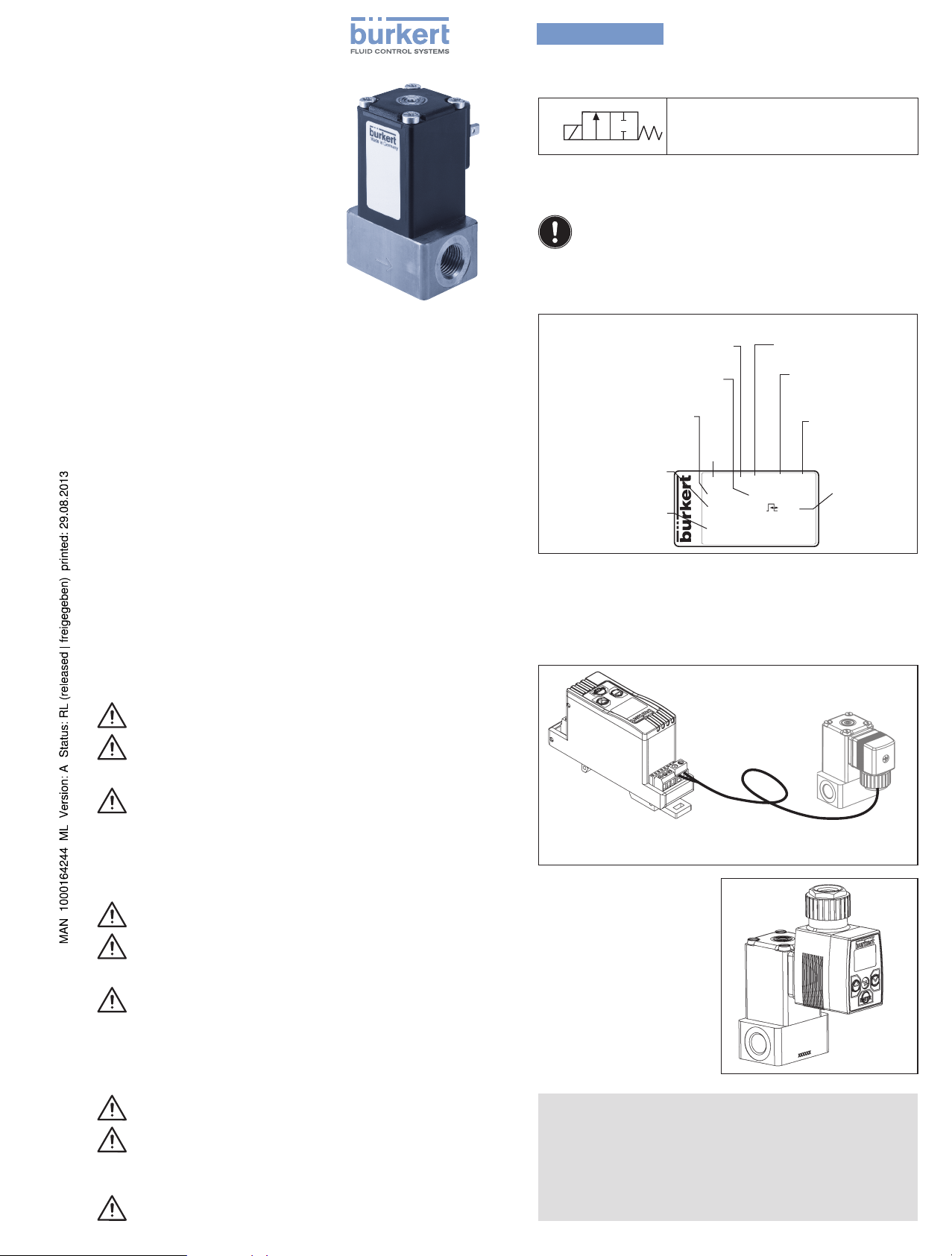
III. ELECTRICAL CONTROL/ ELEKTRISCHE
ANSTEUERUNG / COMMANDE ÉLECTRIQUE
For all designs (wires and plugs)
Für alle Ausführungen (Litzen, Stecker)
Pour toutes les versions (torons et connecteurs)
Type / Typ 8605
Top-hat rail
variant
Hutschienenvariante
Variante sur profilé chapeau
For plug designs with coil
size 32 mm and 49 mm
Für Steckerausführungen
mit Spulengröße 32 mm und
49 mm
Pour versions avec
connecteurs et tailles de
bobine de 32 et 49 mm
Example with device socket type 2508
Beispiel mit Gerätesteckdose Typ 2508
Example avec connecteur type 2508
Cable lenght / Leitungslänge /
Longueur de ligne: max. 50 m
Type / Typ
8605
SYMBOLES
→
identifie une opération que vous devez effectuer.
Mise en garde contre les blessures graves ou mortelles :
DANGER!
En cas de danger imminent
AVERTISSEMENT!
En cas de danger possible.
Mise en garde contre les blessures légères ou moyennement
graves :
ATTENTION!
attachable
aufsteckbar
enfichable
NOTE /HINWEIS / REMARQUE!
Functional impairment at incorrect PWM frequency!
• For PWM frequency see instructions for the control electronics.
Funktionsbeeinträchtigung bei falscher PWM-Frequenz!
• PWM-Frequenz siehe Anleitung der Ansteuerelektronik.
Dysfonctionnement dû à une mauvaise fréquence PWM !
• Fréquence PWM, voir instructions de service de l’électronique
de commande.
Page 2
English
Type 2861 ... 2875
1. OPERATING INSTRUCTIONS
The operating instructions contain important information.
• Read the instructions carefully and follow the safety instructions
in particular, and also observe the operating conditions.
• Keep the instructions in a location where they are available to
every user.
• The liability and warranty for the proportional valve are void if the
operating instructions are not followed.
2. INTENDED USE
The direct-acting proportional valve can be used as an actuating
element for the process control.
• Do not use in potentially explosive areas.
• Do not use outside.
• Operate only when in perfect condition and pay attention to correct
storage, transportation, installation and operation.
• Do not make any internal or external changes.
3. BASIC SAFETY INSTRUCTIONS
These safety instructions do not make allowance for any contingencies and events which may arise during installation, operation
and maintenance.
WARNING!
Danger – high pressure!
• Before loosening lines or valves, turn off the pressure and vent
the lines.
Risk of burns/risk of fire if used continuously through hot
device surface!
• Keep the proportional valve away from highly flammable substances and media and do not touch with bare hands.
• Do not obstruct the heat release required for operation.
To prevent injury, ensure the following:
• Secure equipment/device from unintentional actuation.
• Only trained technicians may perform installation and maintenance work.
• After an interruption in the power supply, ensure that the process is restarted in a controlled manner.
• Observe the general regulations of technology.
5. INSTALLATION
WARNING!
Risk of injury from high pressure in the equipment.
• Before loosening lines or valves, turn off the pressure and vent
the lines.
Installation position: any position, preferably with actuator above.
→ Clean pipelines and flange connections.
→ Install dirt filter in the direction of flow in front of the valve
(mesh size 0.02 – 0.4 mm; according to orifice).
WARNING!
Danger from medium!
• Make sure that the supplied seal fits properly.
→ Insert seal into valve.
NOTE!
• The proportional valve must not be removed and the central
adjusting screw must not be adjusted.
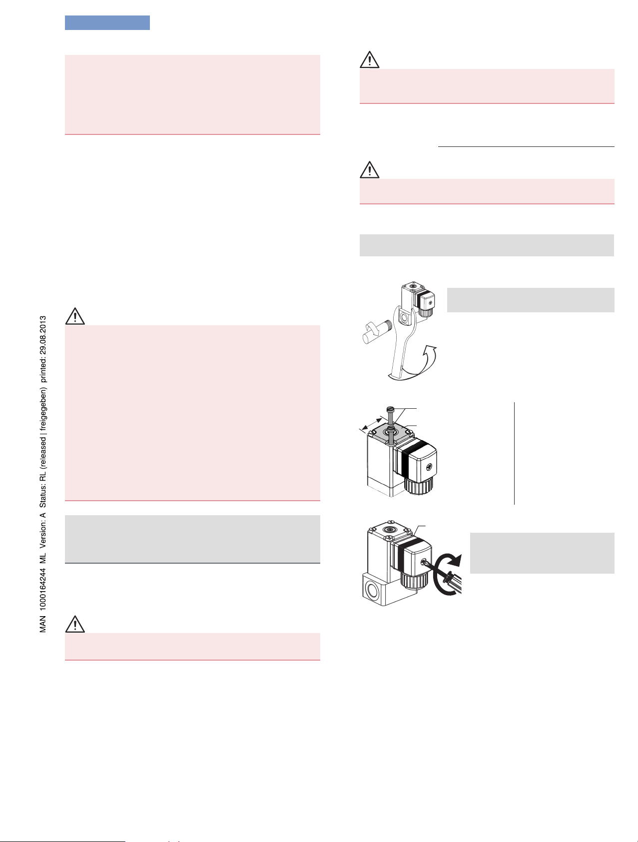
Screwing in pipeline:
NOTE!
• Use suitable tool (open-end wrench)
and do not use coil as a lever arm.
→ Hold the proportional valve on the fluid
housing using an open-end wrench.
→ Screw in pipeline.
→ Check installation for leaks.
Attaching the mounting plate:
Tightening torque
according to coil size:
20 mm = max. 1.0 Nm
32 mm = max. 1.2 Nm
49 mm = max. 1.5 Nm
mm*
Fastening screws (2)
Mounting plate
* Coil size
Electrostatic sensitive components/modules!
Observe the requirements in accordance with EN 61340-5-1 and
5-2 to minimize/avoid the possibility of damage caused by a sudden
electrostatic discharge!
4. TECHNICAL DATA
4.1. Operating conditions
CAUTION!
Malfunction in unauthorized temperature range.
• Avoid exceeding or dropping below the temperature range.
Ambient temperature: 0 ... +55 °C
Medium temperature: -10 ... +90 °C
Media: neutral gases, technical vacuum
Protection class: IP65 in accordance with DIN EN 60529
4.2. Mechanical and pneumatic data
Materials, pressure range, line connectors: see rating plate
4.3. Electrical Data
Operating voltage, power input: see rating plate.
Nominal operating mode: Long-term operation ED 100 % in
accordance with DIN EN 60034-1
Electrical connection: (depending on type and design) wires, plug
tabs in accordance with DIN EN 175301-803 shape A, shape B
Connecting device socket:
Seal
NOTE!
• Note the voltage and current
type as specified on the rating
plate. Ensure that the seal is fitted
correctly.
→ Insert seal.
max.
0.9 Nm
→ Attach device socket and secure
with screw.
Tightening torque max. 0.9 Nm.
→ Connect protective conductor.
6. MAINTENANCE
Under normal operating conditions, the valve is maintenance-free.
7. MALFUNCTIONS
If malfunctions occur, check
• the line connectors,
• whether the operating pressure is within the permitted range,
• the power supply and valve control.
8. TRANSPORTATION, STORAGE, DISPOSAL
• Transport and store the proportional valve in shock-resistant
packaging to protect against moisture and dirt.
• Permitted storage temperature: -20 … +70 °C.
• Dispose of the device and packaging according to the applicable disposal and environmental protection regulations.
Page 3

deutsch
Typ 2861 ... 2875
1. DIE BEDIENUNGSANLEITUNG
Die Bedienungsanleitung enthält wichtige Informationen.
• Die Anleitung sorgfältig lesen und besonders die Hinweise zur
Sicherheit, sowie die Betriebsbedingungen beachten.
• Die Anleitung so aufbewahren, dass sie jedem Benutzer zur
Verfügung steht.
• Die Haftung und Gewährleistung für das Proportionalventil
entfällt, wenn die Anweisungen der Bedienungsanleitung nicht
beachtet werden.
2. BESTIMMUNGSGEMÄSSER GEBRAUCH
Das direktwirkende Proportionalventil kann als Stellglied zur Prozessregelung eingesetzt werden.
• Nicht in explosionsgefährdeten Bereichen einsetzen.
• Nicht im Außenbereich einsetzen.
• Nur in einwandfreiem Zustand betreiben und auf sachgerechte
Lagerung, Transport, Installation und Bedienung achten.
• Keine inneren oder äußeren Veränderungen vornehmen.
3. GRUNDLEGENDE SICHERHEITSHINWEISE
Diese Sicherheitshinweise berücksichtigen keine Zufälligkeiten und
Ereignisse, die bei Montage, Betrieb und Wartung auftreten können.
WARNUNG!
Gefahr durch hohen Druck!
• Vor dem Lösen von Leitungen oder Ventilen den Druck abschalten und Leitungen entleeren.
Verbrennungsgefahr/Brandgefahr bei Dauerbetrieb durch
heiße Geräteoberfläche!
• Das Proportionalventil von leicht brennbaren Stoffen und
Medien fernhalten und nicht mit bloßen Händen berühren.
• Die für den Betrieb notwendige Wärmeabfuhr nicht behindern.
Zum Schutz vor Verletzungen beachten:
• Anlage/Gerät vor unbeabsichtigter Betätigung sichern.
• Nur geschultes Fachpersonal darf Installations- und Instandhaltungsarbeiten ausführen.
• Nach Unterbrechung der elektrischen Versorgung für einen
kontrollierten Wiederanlauf des Prozesses sorgen.
• Die allgemeinen Regeln der Technik einhalten.
5. INSTALLATION
WARNUNG!
Verletzungsgefahr durch hohen Druck in der Anlage.
• Vor dem Lösen von Leitungen oder Ventilen den Druck abschalten und Leitungen entleeren.
Einbaulage: beliebig, vorzugsweise Antrieb oben.
→ Rohrleitungen und Flanschanschlüsse säubern.
→ Schmutzfilter in Strömungsrichtung vor dem Ventil einbauen
(Maschenweite 0,02 ... 0,4 mm; je nach Nennweite).
WARNUNG!
Gefahr durch Medium!
• Auf den richtigen Sitz der mitgelieferten Dichtungen achten.
→ Dichtung in Ventil einlegen.
HINWEIS!
• Das Proportionalventil darf nicht demontiert und die zentrale
Justierschraube nicht verstellt werden.
Rohrleitung einschrauben:
HINWEIS!
• Geeignetes Werkzeug (Gabelschlüssel)
verwenden und Spule nicht als Hebelarm benutzen.
→ Das Proportionalventil mit einem Gabel-
schlüssel am Fluidgehäuse festhalten.
→ Rohrleitung einschrauben.
→ Installation auf Dichtheit prüfen.
Befestigen der Montageplatte:
Anzugsdrehmoment
bei Spulengröße:
20 mm = max. 1,0 Nm
32 mm = max. 1,2 Nm
49 mm = max. 1,5 Nm
mm*
Befestigungsschrauben (2)
Montageplatte
* Spulengröße
Elektrostatisch gefährdete Bauelemente / Baugruppen!
Beachten Sie die Anforderungen nach EN 61340-5-1 und 5-2, um
die Möglichkeit eines Schadens durch schlagartige elektrostatische
Entladung zu minimieren bzw. zu vermeiden!
4. TECHNISCHE DATEN
4.1. Betriebsbedingungen
VORSICHT!
Funktionsausfall bei unzulässigem Temperaturbereich.
• Über- oder Unterschreitung des Temperaturbereichs
vermeiden.
Umgebungstemperatur: 0 ... +55 °C
Mediumstemperatur: -10 ... +90 °C
Medien: neutrale Gase, technisches Vakuum
Schutzart: IP65 nach DIN EN 60529
4.2. Mechanische und pneumatische Daten
Werkstoffe, Druckbereich, Leitungsanschlüsse: siehe Typschild
4.3. Elektrische Daten
Betriebsspannung, Leistungsaufnahme: siehe Typschild.
Nennbetriebsart: Dauerbetrieb ED 100 % nach DIN EN 60034-1
Elektrischer Anschluss: (abhängig von Typ und Ausführung) Litzen,
Steckerfahnen nach DIN EN 175301-803 Form A, Form B
Gerätesteckdose anschließen:
Dichtung
HINWEIS!
• Spannung und Stromart laut
Typschild beachten. Auf einwandfreien Sitz der Dichtung achten.
→ Dichtung einlegen.
→ Gerätesteckdose aufstecken und
mit Schraube befestigen.
max.
0,9 Nm
6. WARTUNG
Das Ventil arbeitet unter Normalbedingungen wartungsfrei.
7. STÖRUNGEN
Überprüfen Sie bei Störungen
• die Leitungsanschlüsse,
• ob sich der Betriebsdruck im zulässigen Bereich befindet,
• die Spannungsversorgung und Ventilansteuerung.
8. TRANSPORT, LAGERUNG, ENTSORGUNG
• Das Proportionalventil vor Nässe und Schmutz geschützt in
einer stoßfesten Verpackung transportieren und lagern.
• Zulässige Lagertemperatur: -20 … +70 °C.
• Bei der Entsorgung von Gerät und Verpackung die geltenden
Entsorgungsvorschriften und Umweltbestimmungen einhalten.
Anzugsdrehmoment max. 0,9 Nm.
→ Schutzleiter anschließen.
Page 4

français
Type 2861 ... 2875
1. INSTRUCTIONS DE SERVICE
Les instructions de service contiennent des informations
importantes.
• Lire attentivement les instructions et tenir particulièrement compte
des consignes de sécurité ainsi que des conditions d'exploitation.
• Conserver les instructions afin qu'elles soient accessibles à tous
les utilisateurs.
• La responsabilité et la garantie légale concernant la vanne proportionnelle sont exclues en cas de non-respect des instructions
de service.
2. UTILISATION CONFORME
La vanne proportionnelle à action directe peut être utilisée comme
élément de réglage pour la régulation du process.
• Ne pas utiliser dans des zones présentant des risques d’explosion.
• Ne pas utiliser à l’extérieur.
• Utiliser uniquement en parfait état et veiller au stockage, au
transport, à l'installation et à l'utilisation conformes.
• Ne pas effectuer de modifications internes ou externes.
3. CONSIGNES DE SÉCURITÉ FONDAMENTALES
Ces consignes de sécurité ne tiennent pas compte des hasards et
des événements pouvant survenir lors du montage, de l'exploitation
et de l'entretien.
AVERTISSEMENT !
Danger dû à la haute pression !
• Avant de desserrer les conduites et les vannes, couper la pression et purger l'air des conduites.
Risque de brûlures/d'incendie en fonctionnement continu dû
à des surfaces d'appareils brûlantes !
• Tenir les substances et les fluides facilement inflammables à
l'écart de la vanne et ne pas toucher celle-ci à mains nues.
• Ne pas gêner l'évacuation de la chaleur nécessaire au
fonctionnement.
Pour prévenir les blessures, veuillez tenir compte de ce qui suit :
• Empêcher tout actionnement involontaire de l'installation/de
l'appareil.
• Seul du personnel qualifié peut effectuer l'installation et la
maintenance.
• Garantir un redémarrage contrôlé du process après la coupure
de l'alimentation électrique.
• Respecter les règles générales de la technique.
Eléments/sous-groupes sujets aux risques électrostatiques !
Respecter les exigences selon EN 61340-5-1 et 5-2 pour minimiser ou éviter la possibilité d'un dommage causé par une soudaine
décharge électrostatique !
4. CARACTÉRISTIQUES TECHNIQUES
4.1. Conditions d'exploitation
ATTENTION !
Panne en cas de plage de température non autorisée.
• Eviter d'être au-dessus ou en dessous de la plage de température.
Température ambiante : 0 ... +55 °C
Température du fluide : -10 ... +90 °C
Fluides : gaz neutres, vide technique
Type de protection : IP65 selon DIN EN 60529
4.2. Caractéristiques mécaniques et pneumatiques
Matériaux, plage de pression, raccords de conduite : voir plaque
signalétique
4.3. Caractéristiques électriques
Tension de service, puissance absorbée : voir plaque signalétique.
Mode opératoire nominal : fonctionnement continu ED 100 %
selon DIN EN 60034-1
Raccordement électrique : (en fonction du type et de la version)
torons, barettes de raccordement selon DIN EN 175301-803,
forme A, forme B
5. INSTALLATION
AVERTISSEMENT !
Risque de blessures dû à la présence de haute pression
dans l'installation.
• Avant de desserrer les conduites et les vannes, couper la pression et purger l'air des conduites.
Position de montage : au choix, de préférence actionneur vers le
haut.
→ Nettoyer les tuyauteries et les raccordements à bride.
→ Monter le filtre à impuretés dans le sens de l'écoulement en amont
de la vanne (mailles de 0,02 à 0,4 mm ; selon diamètre nominal).
AVERTISSEMENT !
Danger dû au fluide !
• Veiller au bon positionnement des joints fournis.
→ Placer le joint dans la vanne.
REMARQUE !
• Le démontage de la vanne proportionnelle ainsi que le réglage
de la vis d'ajustage centrale sont interdits.
Visser la tuyauterie :
REMARQUE !
• Utiliser des outils appropriés (clé plate)
et ne pas utiliser la bobine comme levier.
→ Maintenir la vanne proportionnelle avec
une clé plate sur le boîtier de fluide.
→ Visser la tuyauterie.
→ Contrôler l'étanchéité de l'installation.
Fixation de la plaque de montage :
Vis de fixation (2)
mm*
Raccorder la prise de l'appareil :
Plaque de montage
* Taille de bobine
Joint
REMARQUE !
Respectez la tension et le type de courant
selon la plaque signalétique. Veiller à
l'installation correcte du joint.
Couple de serrage
avec taille de bobine :
20 mm = max. 1,0 Nm
32 mm = max. 1,2 Nm
49 mm = max. 1,5 Nm
→ Placer le joint.
→ Mettre la prise de l’appareil en place
max.
0,9 Nm
et la fixer avec une vis.
Couple de serrage max. 0,9 Nm.
→ Raccorder le conducteur de protection.
6. ENTRETIEN
Dans des conditions normales, la vanne ne nécessite aucun entretien.
7. PANNES
En présence de pannes, vérifier
• les raccords de conduite,
• la présence d'une pression de service située dans la plage autorisée,
• l'alimentation en tension et la commande de la vanne.
8. TRANSPORT, STOCKAGE, ÉLIMINATION
• Transporter et stocker la vanne proportionnelle à l'abri de l'humidité
et des impuretés et dans un emballage résistant aux chocs.
• Température de stockage autorisée : -20 à +70 °C.
• Lors de l'élimination de l'appareil et de l'emballage, respecter
les prescriptions en matière d’élimination des déchets et de
protection de l’environnement en vigueur.
 Loading...