

Page 1
PTB 00 ATEX 2202 X
Magnetspule Typ 7..-...
Device with IIC 2G Ex mb or IIC 2G Ex e mb-approval
Gerät mit IIC 2G Ex mb bzw. IIC 2G Ex e mb-Zulassung
Appareils avec mode de protection IIC 2G Ex mb et IIC 2G Ex e mb
Operating Instructions
Bedienungsanleitung
Manuel d‘utilisation
Page 2
We reserve the right to make technical changes without notice.
Technische Änderungen vorbehalten.
Sous réserve de modification techniques.
© Bürkert Werke GmbH, 2003 - 2013
Operating Instructions 1310/17_EU-ML_00804437 / Original DE
Page 3
Contents
PTB 00 ATEX 2202 X
1 OPERATING INSTRUCTIONS ................................................................4
1.1 Symbols
2 AUTHORIZED USE ......................................................................................5
2.1 Restrictions
2.2 Explosion protection approval ................................................... 5
2.3 Special instructions ..................................................................... 6
3 GENERAL SAFETY INSTRUCTIONS ..................................................6
4 GENERAL INFORMATION ........................................................................7
4.1 Contact address ...........................................................................7
4.2 Warranty
4.3 Information on the Internet ......................................................... 7
5 APPLICATION CONDITIONS ..................................................................8
5.1 Special conditions .......................................................................8
5.2 Operating conditions...................................................................8
5.3 Installation conditions ..................................................................9
5.4 Application in gas pumps .........................................................10
5.5 Model with a terminal box ........................................................10
..........................................................................................4
....................................................................................5
......................................................................................... 7
6 TECHNICAL DATA ..................................................................................... 11
6.1 Rating plate .................................................................................11
6.2 Conformity
6.3 Standards
7 ASSEMBLY AND DISASSEMBLY ...................................................... 12
7.1 Safety instructions .....................................................................12
7.2 Assembly
7.3 Electrical connection .................................................................13
7.4 Disassembly
8 START-UP
9 MAINTENANCE AND REPAIRS .......................................................... 15
9.1 Maintenance
9.2 Repairs
9.3 Troubleshooting
10 TRANSPORTATION, STORAGE, DISPOSAL ................................ 16
11 ACCESSORIES
...................................................................................11
....................................................................................11
......................................................................................13
................................................................................14
...................................................................................................... 15
................................................................................15
.........................................................................................15
..........................................................................15
........................................................................................... 16
english
3
Page 4
PTB 00 ATEX 2202 X
Operating instructions
1 OPERATING INSTRUCTIONS
The operating instructions describe the entire life cycle of the device.
Keep these instructions in a location which is easily accessible to
every user and make these instructions available to every new owner
of the device.
WARNING!
The operating instructions contain important safety
information!
Failure to observe these instructions may result in hazardous situations. The operating instructions must be read and understood.
▶ Carefully read the operating instructions before using the device.
▶ Study in particular the chapters entitled “Authorized use”, and
“General information” as well as the chapter “Application
conditions”.
1.1 Symbols
To identify important information, the following symbols are used in
the operating instructions:
DANGER!
Warns of an immediate danger!
▶ Failure to observe the warning will result in a fatal or serious
injury.
WARNING!
Warns of a potentially dangerous situation!
▶ Failure to observe the warning may result in serious injuries or
death.
CAUTION!
Warns of a possible danger!
▶ Failure to observe this warning may result in a moderate or
minor injury.
NOTE!
Warns of damage to property!
• Failure to observe the warning may result in damage to device
or equipment.
Indicates important additional information, tips and
recommendations.
Refers to information in these operating instructions or in
other documentation.
▶ Designates an instruction to prevent risks.
→ Designates a procedure which you must carry out.
4
english
Page 5
PTB 00 ATEX 2202 X
Authorized use
2 AUTHORIZED USE
Non-authorized use of the solenoid coil Type 7..-... may represent
a hazard to people, nearby equipment and the environment.
▶ The device may be used only for the applications designated in
chapter “Application conditions” and in conjunction with thirdparty devices and components recommended and authorized by
Bürkert. Follow the directions of these operating instructions as
well as the operating conditions and authorized data specified in
the chapter entitled “Application conditions”.
▶ The device is used exclusively as a solenoid valve for media
permitted according to the data sheet and for use in explosion
group IIC, category 2G and temperature class T4 or T6
(see specifications on the approval plate).
▶ The solenoid coil is available in two mechanical designs:
- Open / Close version
- proportional acting version (solenoid core opens depending
on the electrical current applied.)
Both solenoid systems are purely mechanical variants and have
identical safety data.
▶ The applied protection class is the encapsulation EX mb for
coils with cable connection or encapsulation with increased
safety EX e mb for coils with terminal box.
▶ The solenoid coil Type 7..-... is used to actuate valves which
control gaseous or liquid media. The coil is either encapsulated
with the core feed pipe of the fitting or mounted on the core
feed pipe of the fitting and secured with a nut. This always
creates a closed system and the devices may also be used as
a category 2 device to control gas in gas pumps. The valve bodies can be made of metal or polyamide.
▶ Correct transportation, proper storage and installation,
and careful operation and maintenance are essential for
ensuring problem-free and reliable operation of the system.
Any other or more extensive usage is considered contrary to
authorized use. Bürkert is not liable for any resulting damage.
The user alone bears the risk.
▶ Use the device only for its intended purpose.
2.1 Restrictions
If exporting the system/device, observe any existing restrictions.
2.2 Explosion protection approval
The EX approval is only valid if the modules and components authorized by Bürkert are used as described in these operating instructions.
The solenoid coil Type 7..-... may be used only in combination with the
additional components released by Bürkert, otherwise the EX approval
will be voided! If any unauthorized changes are made to the device,
modules or components, the EX approval will also be voided.
The EC type-examination certificate PTB 00 ATEX 2202 X was
issued by the
PTB (Physikalisch Technische Bundesanstalt)
Bundesallee 100
D-38116 Braunschweig
which also audits production (CE 102).
The EC type-examination certificate can be found on the Internet at:
www.burkert.com
english
5
Page 6
PTB 00 ATEX 2202 X
Authorized use
2.3 Special instructions
WARNING!
Danger due to electrostatic discharge!
In the event of a sudden discharge from electrostatically charged
devices or individuals, there is a risk of an explosion in the
explosion-risk area.
▶ Take suitable measures to ensure that no electrostatic dis-
charges can build up in the explosion-risk area.
▶ Clean the device surface by gently wiping it with a damp or anti-
static cloth only.
3 GENERAL SAFETY INSTRUCTIONS
These safety instructions do not make allowance for any
• Contingencies and events which may arise during the assembly,
operation, and maintenance of the devices.
• Local safety regulations – the operator is responsible for observing these
regulations, also in relation to the installation personnel.
DANGER!
Risk of explosion!
Following installation, solenoid coil and valve body form a closed
system. If used in the explosion-risk area, there is a danger of
explosion if the system is opened during operation!
▶ The system must not be disassembled during operation.
Risk of electric shock!
There is a serious risk of injury when reaching into the equipment.
▶ Only trained electrical engineers may work on the electrical
system.
▶ Before starting work, always switch off the power supply and
safeguard to prevent re-activation!
▶ Observe applicable accident prevention and safety regulations
for electrical equipment!
DANGER!
Risk of burns/risk of fire during long-term operation!
The solenoid coil may become very hot during long-term operation.
▶ Take hold of a device which has been running for a prolonged
period with protective gloves only.
Danger – high pressure!
When reaching into the system, there is an acute risk of injury.
▶ Only skilled and instructed personnel may work on the system
with suitable tools.
▶ Before disconnecting lines and valves, switch off the pressure
and bleed the lines.
▶ During installation note the flow direction.
▶ Observe applicable accident prevention and safety regulations
for pressurized devices.
▶ After an interruption in the power supply or fluid supply, ensure
that the process is restarted in a defined or controlled manner!
6
english
Page 7
PTB 00 ATEX 2202 X
General information
WARNING!
General hazards!
▶ Do not use the valve fitting or the complete device as a lever to
screw the valve into the line system.
▶ Do not physically stress the device (e.g. by placing objects on it
or standing on it).
▶ Do not make any external modifications to the device housings.
Do not paint housing parts or screws.
▶ Observe the generally acknowledged safety rules for resource
planning and operation of the solenoid coil Type 7..-... and the
associated solenoid valve.
Unintentional activation or unauthorized impairment of the system
may cause general hazardous situations through to physical injury.
▶ Take appropriate measures to prevent the system from being
accidentally actuated!
▶ Do not make any unauthorized changes to the system.
The solenoid coil Type 7..-... was developed with due consideration given to the accepted safety rules and is state-of-the-art.
Nevertheless, dangerous situations may occur.
Operate the solenoid coil Type 7..-... and the associated
solenoid valve in perfect working order only and in accordance
with the operating instructions.
4 GENERAL INFORMATION
4.1 Contact address
Germany
Bürkert Fluid Control Systems
Sales Center
Christian-Bürkert-Str. 13-17
D-74653 Ingelfingen
Tel. + 49 (0) 7940 - 10 91 111
Fax + 49 (0) 7940 - 10 91 448
E-mail: info@de.buerkert.com
International
Contact addresses can be found on the final pages of the printed
operating instructions.
And also on the Internet at: www.burkert.com
4.2 Warranty
The warranty is only valid if the device is used as intended in accordance
with the specified application conditions.
4.3 Information on the Internet
The operating instructions and data sheets for Bürkert products can
be found on the Internet at: www.burkert.com
english
7
Page 8
5 APPLICATION CONDITIONS
5.1 Special conditions
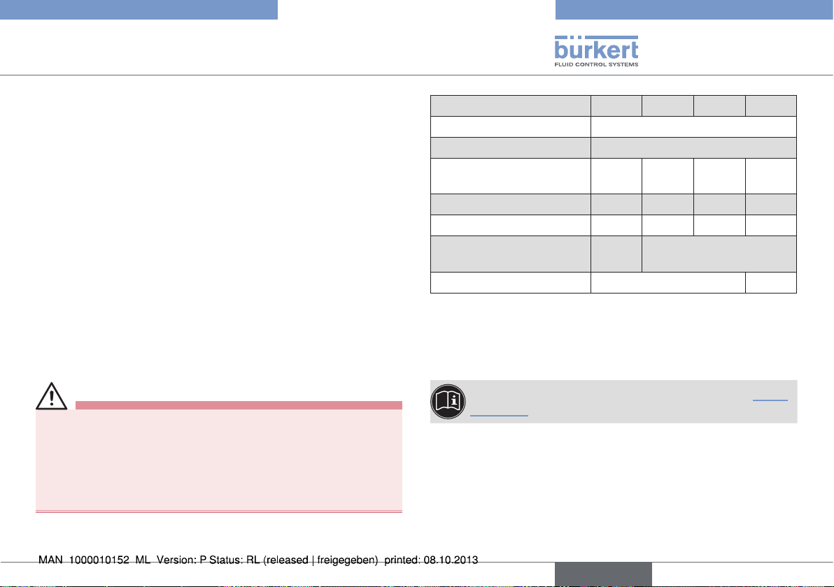
• To protect each solenoid coil against short-circuit, a fuse (max.
3 x Ib in accordance with IEC 127), corresponding to the rated
current, or a motor protection switch with short-circuit and thermal
quick release (set to rated current) must be connected upstream.
This fuse may be housed in the associated supply unit or must
be connected separately upstream. The rated voltage of the fuse
must be equal to or greater than the indicated nominal voltage
of the solenoid. The breaking capacity of the fuse insert must
be equal to or greater than the maximum short-circuit current
accepted at the installation location (usually 1500 A).
The nominal value of the fuse is indicated on the solenoid.
Fuse ... A
PTB 00 ATEX 2202 X
Application conditions
The application temperature range indicated in the "Electrical
•
Data" (Chapter 5.2. Operating conditions) must be observed for
each type.
• The attachment of a terminal box changes the designation of the
ignition protection type of the solenoid coil 07..-...
• The permanently installed connection line of the solenoid must be
connected in a housing which meets the requirements of a recognized ignition protection type according to EN 60079-0, If the
connection is made in an area where there is a risk of explosion.
• The solenoid coil Type 07..-... is suitable for individual assembly
only.
5.2 Operating conditions
When operating the solenoid coils Type 7..-..., the following requirements have to be observed.
5.2.1 Materials
For the selection of materials for the system observe the applicationspecific, safety requirements.
Valve body:
DANGER!
• If the solenoid coil Type 07..-... is used as a category 2 device for
the control of gas in gas pumps, the valve body must be made of
metal. The coil is mounted on the core feed pipe and may only be
dismantled by the manufacturer. The valves always form a closed
system.
8
english
Risk of explosion!
If the system is used as a category 2 device, only valve bodies
made of metal can ensure the required safety for the control of
gas in gas pumps!
▶ Use only valve bodies made of metal (brass, aluminum or stainless
steel) for the control of gas in gas pumps with category 2 devices.
Page 9
PTB 00 ATEX 2202 X
Application conditions
•
For use in gas pumps:
Metal (brass, aluminum, stainless steel)
• Other applications:
Metal (brass, aluminum, stainless steel) or plastic
(e.g. polyamide PA 6 GV...)
Sheathing of the electrical connection lines:
• For terminal box design:
without connection line
• For cable design:
Rubber hose
5.2.2 Minimum dimensions
Valve body:
56 mm x 49 mm x 36 mm (L x W x H)
A larger valve body with improved thermal conductivity may
be used at any time.
5.2.3 Operating temperature range:
DANGER!
Risk of explosion!
If the max. permitted temperature values for the coil Type 7..-... are
exceeded, there is a danger of explosion.
▶ It is essential to observe the temperature specifications for the coil.
▶ Observe any restrictions by the max. permitted values for the
solenoid valve combined with the coil.
Type designation 71. 72. 73. 735
Nominal voltage [V]
Current type
Rated current
Nominal power (W)
Temperature class
Ambient temperature (°C)
Voltage tolerance (%)
0.012
... 0.38
5 15 7 6
T6 T4 T6 T6
–40 ...
+60
12 ... 380
AC/DC
0.038
... 1.2
±10% ±20%
0.017
... 0.53
–40 ...+40
0.013
... 0.42
5.3 Installation conditions
The solenoid coils Type 7..-... are suitable for individual assembly only.
The connection lines must be laid permanently to protect against
damage.
Also observe the specifications in the chapter entitled “Technical data”.
english
9
Page 10
PTB 00 ATEX 2202 X
Application conditions
5.4 Application in gas pumps
DANGER!
Risk of explosion!
Following installation, solenoid coil and valve body form a closed
system. If used in the explosion-risk area, there is a danger of
explosion if the system is opened during operation!
▶ The system must not be disassembled during operation.
▶ The valve body may be repaired by the manufacturer only.
Solenoid valves together with the coil Type 7..-... may be used as
category 2 devices only for the control of gas if there is no air and
no oxygen in the closed system.
▶ Ensure that the closed system contains no air or oxygen or can-
not be penetrated by air or oxygen.
▶ When switching off or starting up the system, ensure that nei-
ther air nor oxygen has penetrated the system.
If the system is used as a category 2 device, only valve bodies
made of metal can ensure the required safety for the control of
gas in gas pumps!
▶ Use only valve bodies made of metal (brass, aluminum or stain-
less steel) for the control of gas in gas pumps with category 2
devices.
5.5 Model with a terminal box
DANGER!
Risk of explosion!
▶ Only specified cables and lines may be used.
▶ The operator must ensure an adequate strain relief.
▶ Lines with an outer diameter from 6 mm to 13 mm may be used.
Observe the maximum thermal load of the installed cables and
lines.
▶ The inserted break-out seal must be adjusted to the diameter of
the cable/line.
▶ The rated cross-section of the cables/line cores must be at
least 0.75 mm² and must not exceed 2.5 mm².
▶ Screws for attaching the cover of the terminal box must be
tightened to a torque of 100 Ncm (±5%).
10
english
Page 11
PTB 00 ATEX 2202 X
Technical data
6 TECHNICAL DATA
DANGER!
Risk of explosion!
If the safety data and values specified on the rating plate are
not observed or maintained, hazardous situations may be the
consequence!
▶ Observe the protection type and temperature class when using
the device.
It is a safety risk to exceed the voltage indicated on the rating
plate, as this may cause the device to overheat!
▶ Do not connect the device to a higher voltage than indicated on
the rating plate.
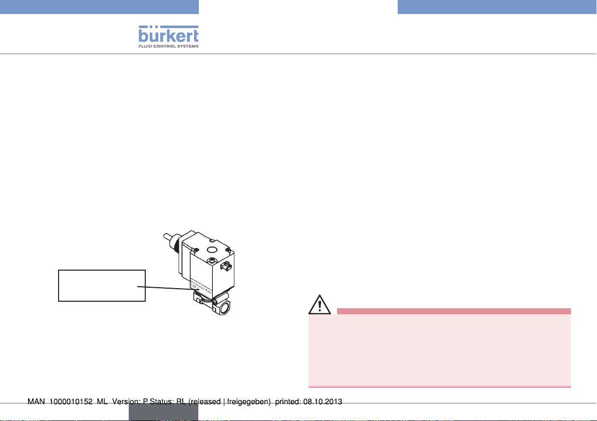
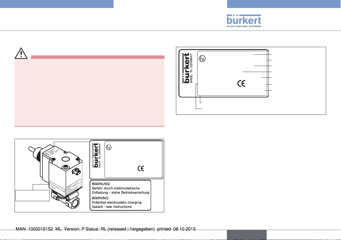
6.1 Rating plate
PTB 00 ATEX 2202 X
II 2G Ex mb IIC T4 Gb
IECEx PTB 13.0011X
Ex mb II T4 Gb
722-G629092 24V~15W
S/N xxxxx
999999
Fuse
... A
0102
W24LA
Inscription on the rating plate:
PTB 00 ATEX 2202 X
II 2G Ex mb IIC T4 Gb
IECEx PTB 13.0011X
Ex mb II T4 Gb
722-G629092 24V~15W
S/N xxxxx
999999
Identification number
Serial number
Fig. 2: Example inscription rating plate
0102
W24LA
PTB approval number
ATEX identification
IECEx approval number
IECEx identification
Electrical data
Licensing authority
Date of manufacture
6.2 Conformity
The solenoid coil Type 7..-... conforms to the EC directives
according to the EC Declaration of Conformity.
6.3 Standards
The applied standards which are used to demonstrate compliance
with the EC Directives are listed in the EC type test certificate and/
or the EC Declaration of Conformity.
Fig. 1: Example of a rating plate for coil Type 7..-...
english
11
Page 12
PTB 00 ATEX 2202 X
Assembly and disassembly
7 ASSEMBLY AND DISASSEMBLY
7.1 Safety instructions
DANGER!
Risk of explosion!
Following installation, solenoid coil and valve body form a closed
system. If used in the explosion-risk area, there is a danger of
explosion if the system is opened during operation!
▶ The system must not be disassembled during operation.
Risk of short-circuit!
Damaged connection lines may cause a short-circuit.
▶ The connection lines for the coil must be laid permanently and
protected against damage.
Risk of burns/risk of fire during long-term operation!
The solenoid coil may become very hot during long-term operation.
▶ Take hold of a device which has been running for a prolonged
period with protective gloves only.
DANGER!
Risk of electric shock!
There is a serious risk of injury when reaching into the equipment.
▶ Live terminals in the terminal box may cause an electric shock,
short-circuit or explosion. Switch off the power supply. Only then
open the terminal box.
▶ The connection lines of the electromagnets must be permanently
installed in such a way that they are adequately protected from
mechanical damage.
▶ Only trained electrical engineers may work on the electrical system.
▶ Before starting work, always switch off the power supply and
safeguard to prevent re-activation!
▶ Observe applicable accident prevention and safety regulations
for electrical equipment!
WARNING!
Danger – high pressure!
When reaching into the system, there is an acute risk of injury.
▶ Only skilled and instructed personnel may work on the system
with suitable tools.
▶ Before disconnecting lines and valves, switch off the pressure
and bleed the lines.
▶ Observe applicable accident prevention and safety regulations
for pressurized devices.
▶ After an interruption in the power supply or fluid supply, ensure
that the process is restarted in a defined or controlled manner.
▶ During installation note the flow direction.
DANGER!
▶ The operator must ensure an adequate strain relief.
▶ Lines with an outer diameter of 6 mm ... 13 mm can be used.
Observe the maximum thermal load of the installed cables and
lines.
▶ The inserted break-out seal must be adjusted to the diameter of
the cable/line.
▶ The rated cross-section of the cables/line cores must be at least
0.75 mm² and must not exceed 2.5 mm².
▶ Screws for attaching the cover of the terminal box must be tight-
ened to a torque of 100 Ncm (±5%).
12
english
Page 13
PTB 00 ATEX 2202 X
Assembly and disassembly
7.2 Assembly
Any installation position. Preferably, the actuator should be
at the top.
Prior to the installation:
→ Clean any dirt from the pipelines and flanged connections.
Assembly:
WARNING!
Risk of injury from leaking connections.
Risk of explosion!
There is a danger of explosion in tank installations if oxygen or air
penetrates the medium through leaking connections.
Risk of injury from escaping medium!
Medium which escapes through leaking connections may result in
injuries (e.g. burns or chemical burns).
▶ Carefully seal the connection lines.
→ Connect dirt trap upstream.
→ Seal pipeline connections with PTFE tape. The tape must not be
dropped into the pipelines.
→ Screw in pipelines.
Important for function of the device:
Pay attention to the flow direction!
7.3 Electrical connection
DANGER!
Risk of injury due to electrical shock!
▶ Before reaching into the system, switch off the electrical power
supply and secure to prevent reactivation!
▶ Observe applicable accident prevention and safety regulations
for electrical equipment!
If the protective conductor contact between the coil and housing
is missing, there is danger of electrical shock!
▶ Always connect protective conductor.
▶ Check electrical continuity between coil and housing.
The connecting cable is encapsulated with the coil Type
7..-... and cannot be removed.
→ Observe the voltage indicated on the rating plate.
→ Check valve for leakage.
english
13
Page 14
PTB 00 ATEX 2202 X
Assembly and disassembly
7.4 Disassembly
DANGER!
Risk of electric shock!
There is a serious risk of injury when reaching into the equipment.
▶ Only trained electrical engineers may work on the electrical
system.
▶ Before starting work, always switch off the power supply and
safeguard to prevent re-activation!
▶ Observe applicable accident prevention and safety regulations
for electrical equipment!
WARNING!
Danger – high pressure!
When reaching into the system, there is an acute risk of injury.
▶ Only skilled and instructed personnel may work on the system
with suitable tools.
▶ Before disconnecting lines and valves, switch off the pressure
and bleed the lines.
▶ Observe applicable accident prevention and safety regulations
for pressurized devices.
▶ After an interruption in the power supply or fluid supply, ensure
that the process is restarted in a defined or controlled manner.
WARNING
Risk of injury from leaking connections.
Risk of explosion!
There is a danger of explosion in tank installations if oxygen or air
penetrates the medium through leaking connections.
Risk of injury from escaping medium!
Medium which escapes through leaking connections may result in
injuries (e.g. burns or chemical burns).
▶ Carefully seal the connection lines.
→ Disconnect electrical connections
→ Disconnect the valve housing from the pipeline
NOTE!
Malfunctions as a result of contamination!
• In case of new installation, remove old PTFE tape from the connections. Residues or parts of the tape must not get into the
pipeline.
14
english
Page 15
PTB 00 ATEX 2202 X
Start-up
8 START-UP
WARNING!
Danger due to improper operation!
Improper operation may result in injuries as well as damage to the
device and the surrounding area.
▶ Before start-up, ensure that the operating personnel are familiar
with and completely understand the contents of the operating
instructions.
▶ In particular observe the safety instructions and intended use.
▶ The device/system may be started by adequately trained per-
sonnel only.
Before start-up, ensure that
→ the device has been installed correctly,
→ the connection has been made properly,
→ the device is not damaged,
→ all screws have been tightened.
9 MAINTENANCE AND REPAIRS
9.1 Maintenance
The solenoid coil Type 7..-... is maintenance-free if the operating conditions described in this manual are observed.
9.2 Repairs
DANGER!
Danger - improper repairs!
Following repairs, the safety and function of the coil Type 7..-...
and the corresponding solenoid valve cannot be guaranteed
unless the repairs were carried out by the manufacturer.
▶ Have the device repaired by the manufacturer only!
9.3 Troubleshooting
In the event of malfunctions, make sure that
→ the device has been installed correctly,
→ the connection has been made properly,
→ the device is not damaged,
→ the voltage and pressure have been switched on,
→ all screws have been tightened,
→ the pipelines are free.
english
15
Page 16

PTB 00 ATEX 2202 X
Transportation, storage, disposal
10 TRANSPORTATION, STORAGE,
DISPOSAL
NOTE!
Transport damage!
Inadequately protected devices may be damaged during
transportation.
Protect the device against moisture and dirt in shock-resistant
•
packaging during transportation.
• Prevent the temperature from exceeding or dropping below the
permitted storage temperature.
Incorrect storage may damage the device.
• Store the device in a dry and dust-free location!
• Storage temperature -40 to +55 °C.
Damage to the environment caused by device components
contaminated with media.
• Dispose of the device and packaging in an environmentally
friendly manner!
• Observe applicable disposal and environmental regulations.
11 ACCESSORIES
In temperature class T4, a fuse Type 1058 with approval PTB 01
ATEX 2064 U can be used for devices with terminal box design.
Fuse Type 1058 Order number
0.063 A 153717
0.080 A 153745
0.100 A 153718
0.125 A 153719
0.160 A 153720
0.200 A 153731
0.315 A 153733
0.400 A 153734
0.500 A 153735
0.630 A 153736
0.800 A 153737
1.000 A 153738
1.250 A 153739
1.600 A 153746
2.000 A 153740
3.150 A 153742
16
english
Page 17

Inhalt
PTB 00 ATEX 2202 X
1 BEDIENUNGSANLEITUNG
1.1 Darstellungsmittel
2 BESTIMMUNGSGEMÄSSE VERWENDUNG................................19
2.1 Beschränkungen
2.2 Ex-Zulassung
2.3 Besondere Hinweise .................................................................20
3 ALLGEMEINE SICHERHEITSHINWEISE ....................................... 20
4 ALLGEMEINE HINWEISE .......................................................................21
4.1 Kontaktadresse
4.2 Gewährleistung
4.3 Informationen im Internet ..........................................................21
5 EINSATZBEDINGUNGEN
5.1 Besondere Bedingungen .........................................................22
5.2 Betriebsbedingungen
5.3 Montagebedingungen
5.4 Einsatz in Tanksäulen ................................................................24
5.5 Ausführung mit einem Klemmenkasten .................................24
...............................................................................19
...................................................................18
......................................................................18
........................................................................19
...........................................................................21
..........................................................................21
...................................................................... 22
................................................................22
...............................................................23
6 TECHNISCHE DATEN ............................................................................. 25
6.1 Typschild
6.2 Konformität...................................................................................25
6.3 Normen
7 MONTAGE UND DEMONTAGE ........................................................... 26
7.1 Sicherheitshinweise
7.2 Montage
7.3 Elektrischer Anschluss ..............................................................27
7.4 Demontage
8 INBETRIEBNAHME
9 WARTUNG UND REPARATUR.............................................................29
9.1 Wartung
9.2 Reparatur
9.3 Fehlerbehebung
10 TRANSPORT, LAGERUNG, ENTSORGUNG .................................30
11 ZUBEHÖR
......................................................................................25
.........................................................................................25
...................................................................26
.......................................................................................27
..................................................................................28
................................................................................... 29
........................................................................................29
.....................................................................................29
.........................................................................29
..................................................................................................... 30
deutsch
17
Page 18

PTB 00 ATEX 2202 X
Bedienungsanleitung
1 BEDIENUNGSANLEITUNG
Die Bedienungsanleitung beschreibt den gesamten Lebenszyklus
des Geräts. Bewahren Sie diese Anleitung so auf, dass sie für jeden
Benutzer gut zugänglich ist und jedem neuen Eigentümer des Geräts
wieder zur Verfügung steht.
WARNUNG!
Die Bedienungsanleitung enthält wichtige Informationen zur
Sicherheit!
Das Nichtbeachten dieser Hinweise kann zu gefährlichen Situationen
führen. Die Anleitung muss gelesen und verstanden werden.
▶ Lesen Sie die Bedienungsanleitung vor dem Einsatz des Geräts
sorgfältig durch.
▶ Beachten Sie vor allem die Kapitel „Bestimmungsgemäße
Verwendung“, und „Allgemeine Hinweise“ sowie das Kapitel
„Einsatzbedingungen“.
1.1 Darstellungsmittel
Für die Kennzeichnung wichtiger Informationen werden in der
Anleitung folgende Darstellungsmittel verwendet:
GEFAHR!
Warnt vor einer unmittelbaren Gefahr!
▶ Bei Nichtbeachtung sind Tod oder schwere Verletzungen die Folge.
WARNUNG!
Warnt vor einer möglicherweise gefährlichen Situation!
▶ Bei Nichtbeachtung drohen schwere Verletzungen oder Tod.
VORSICHT!
Warnt vor einer möglichen Gefährdung!
▶ Nichtbeachtung kann mittelschwere oder leichte Verletzungen
zur Folge haben.
HINWEIS!
Warnt vor Sachschäden!
• Bei Nichtbeachtung kann Gerät oder Anlage beschädigt werden.
bezeichnet wichtige Zusatzinformationen, Tipps und
Empfehlungen.
verweist auf Informationen in dieser Bedienungsanleitung
oder in anderen Dokumentationen.
▶ markiert eine Anweisung zur Gefahrenvermeidung.
→ markiert einen Arbeitsschritt, den Sie ausführen müssen.
18
deutsch
Page 19

PTB 00 ATEX 2202 X
Bestimmungsgemäße Verwendung
2 BESTIMMUNGSGEMÄSSE
VERWENDUNG
Bei nicht bestimmungsgemäßem Einsatz der Magnetspule
Typ 7..-... können Gefahren für Personen, Anlagen in der
Umgebung und die Umwelt entstehen.
▶ Das Gerät darf nur für die im Kapitel „Einsatzbedingungen“
vorgesehenen Einsatzfälle und nur in Verbindung mit von
Bürkert empfohlenen bzw. zugelassenen Fremdgeräten und
-komponenten verwendet werden. Beachten Sie die Hinweise
dieser Bedienungsanleitung sowie die Einsatzbedingungen und
zulässigen Daten, die im Kapitel „Einsatzbedingungen“ spezifiziert sind.
▶ Das Gerät dient ausschließlich als Magnetventil für die lt. Daten-
blatt zulässigen Medien und für den Einsatz in Explosionsgruppe
IIC, Kategorie 2G und Temperaturklasse T4 oder T6
(siehe Angaben auf dem -Zulassungsschild).
▶ Die Magnetspule ist in zwei mechanischen Ausführungen lieferbar:
- Auf / Zu-Version
- proportionalwirkende Version (Magnetkern öffnet abhängig
vom anliegenden elektrischen Strom.)
Beide Magnetsysteme sind rein mechanische Varianten, die sich
in den sicherheitstechnischen Daten nicht unterscheiden.
▶ Die angewandte Schutzart ist die Vergusskapselung Ex mb
für Spulen mit Kabelanschluss oder die Vergusskapselung mit
erhöhter Sicherheit Ex e mb für Spulen mit Klemmenkasten.
▶ Die Magnetspule Typ 7..-... dient zum Betätigen von Ventilen, die
gasförmige oder flüssige Medien steuern. Die Spule ist entweder mit dem Kernführungsrohr der Armatur vergossen oder sie
wird mit dem Kernführungsrohr der Armatur montiert und mittels
einer Mutter befestigt. Es entsteht immer ein geschlossenes
System und die Geräte dürfen auch in Tanksäulen zur Steue-
rung von Benzin als Kategorie-2-Gerät eingesetzt werden. Die
Ventilkörper können wahlweise aus Metall oder Polyamid sein.
▶ Der einwandfreie und sichere Betrieb des Systems setzt
sachgemäßen Transport, sachgemäße Lagerung und Installation sowie sorgfältige Bedienung und Instandhaltung voraus.
Eine andere oder darüber hinausgehende Benutzung gilt als nicht
bestimmungsgemäß. Für hieraus resultierende Schäden haftet
Bürkert nicht. Das Risiko trägt allein der Anwender.
▶ Das Gerät nur bestimmungsgemäß einsetzen.
2.1 Beschränkungen
Bei der Ausfuhr des Systems/Geräts gegebenenfalls bestehende
Beschränkungen beachten.
2.2 Ex-Zulassung
Die Ex-Zulassung ist nur gültig, wenn die von Bürkert zugelassenen
Module und Komponenten so verwendet werden, wie es in dieser
Bedienungsanleitung beschrieben ist.
Die Magnetspule Typ 7..-... darf nur in Kombination mit den von Bürkert
freigegebenen Zusatzkomponenten eingesetzt werden, andernfalls
erlischt die Ex-Zulassung! Bei unzulässigen Veränderungen am Gerät,
Modulen oder Komponenten erlischt die Ex-Zulassung ebenfalls.
Die EG-Baumusterprüfbescheinigung PTB 00 ATEX 2202 X wurde
von der
PTB (Physikalisch Technische Bundesanstalt)
Bundesallee 100
38116 Braunschweig
ausgestellt, die auch die Fertigung auditiert (CE 102).
Die EG-Baumusterprüfbescheinigung finden Sie im Internet unter:
www.buerkert.de
deutsch
19
Page 20

PTB 00 ATEX 2202 X
Bestimmungsgemäße Verwendung
2.3 Besondere Hinweise
WARNUNG!
Gefahr durch elektrostatische Entladung!
Bei plötzlicher Entladung elektrostatisch aufgeladener Geräte oder
Personen besteht im Ex-Bereich Explosionsgefahr.
▶ Durch geeignete Maßnahmen sicherstellen, dass es im Ex-
Bereich zu keinen elektrostatischen Aufladungen kommen kann.
▶ Die Geräteoberfläche nur durch leichtes Abwischen mit einem
feuchten oder antistatischen Tuch reinigen.
3 ALLGEMEINE
SICHERHEITSHINWEISE
Diese Sicherheitshinweise berücksichtigen keine
• Zufälligkeiten und Ereignisse, die bei Montage, Betrieb und Wartung
der Geräte auftreten können.
• ortsbezogenen Sicherheitsbestimmungen, für deren Einhaltung, auch
in Bezug auf das Montagepersonal, der Betreiber verantwortlich ist.
GEFAHR!
Explosionsgefahr!
Magnetspule und Ventilkörper bilden nach der Montage ein
geschlossenes System. Bei Einsatz im Ex-Bereich besteht bei der
Öffnung des Systems im Betriebszustand Explosionsgefahr!
▶ Das System darf nicht während des Betriebs demontiert werden.
Gefahr durch elektrische Spannung!
Bei Eingriffen in die Anlage besteht akute Verletzungsgefahr.
▶ Arbeiten am elektrischen System dürfen nur von ausgebildeten
Elektrofachkräften durchgeführt werden.
▶ Schalten Sie vor Beginn der Arbeiten in jedem Fall die Span-
nung ab und sichern Sie diese vor Wiedereinschalten!
▶ Beachten Sie die geltenden Unfallverhütungs- und Sicherheits-
bestimmungen für elektrische Geräte!
GEFAHR!
Verbrennungsgefahr/Brandgefahr bei Dauerbetrieb!
Die Magnetspule kann im Dauerbetrieb sehr heiß werden.
▶ Fassen Sie ein Gerät das bereits länger in Betrieb ist nur mit
Schutzhandschuhen an.
Gefahr durch hohen Druck!
Bei Eingriffen in das System besteht akute Verletzungsgefahr.
▶ Arbeiten am System dürfen nur durch fachkundiges und unter-
wiesenes Personal mit geeignetem Werkzeug durchgeführt
werden.
▶ Schalten Sie vor dem Lösen von Leitungen und Ventilen den
Druck ab und entlüften Sie die Leitungen.
▶ Beachten Sie beim Einbau die Durchflussrichtung.
▶ Halten Sie die geltenden Unfallverhütungs- und Sicherheitsbe-
stimmungen für druckbeaufschlagte Geräte ein.
▶ Gewährleisten Sie nach einer Unterbrechung der elektrischen
oder fluidischen Versorgung einen definierten oder kontrollierten
Wiederanlauf des Prozesses!
20
deutsch
Page 21

PTB 00 ATEX 2202 X
Allgemeine Hinweise
WARNUNG!
Allgemeine Gefährdungen!
▶ Benutzen Sie zum Einschrauben des Ventils in das Leitungssys-
tem die Ventilarmatur bzw. das Komplettgerät nicht als Hebel.
▶ Belasten Sie das Gerät nicht mechanisch (z. B. als Ablage für
Gegenstände oder als Trittstufe).
▶ Nehmen Sie keine äußerlichen Veränderungen an den Geräte-
gehäusen vor. Gehäuseteile und Schrauben nicht lackieren.
▶ Halten Sie für die Einsatzplanung und den Betrieb der Magnet-
spule Typ 7..-... und des zugehörigen Magnetventils die allgemein anerkannten sicherheitstechnischen Regeln ein.
Unbeabsichtigtes Betätigen oder unzulässige Beeinträchtigung
des Systems können zu allgemeinen Gefahrensituationen bis hin
zur Körperverletzung führen.
▶ Verhindern Sie durch geeignete Maßnahmen, dass das System
unbeabsichtigt betätigt werden kann!
▶ Nehmen Sie am System keine unerlaubten Änderungen vor.
Die Magnetspule Typ 7..-... wurde unter Einbeziehung der
anerkannten sicherheitstechnischen Regeln entwickelt und
entspricht dem Stand der Technik. Trotzdem können Gefahren
entstehen.
Betreiben Sie die Magnetspule Typ 7..-... und das zugehörige Magnetventil nur in einwandfreiem Zustand und unter
Beachtung der Bedienungsanleitung.
4 ALLGEMEINE HINWEISE
4.1 Kontaktadresse
Deutschland
Bürkert Fluid Control Systems
Sales Center
Christian-Bürkert-Str. 13-17
D-74653 Ingelfingen
Tel. + 49 (0) 7940 - 10 91 111
Fax + 49 (0) 7940 - 10 91 448
E-mail: info@de.buerkert.com
International
Die Kontaktadressen finden Sie auf den letzten Seiten der gedruckten
Bedienungsanleitung.
Außerdem im Internet unter: www.burkert.com
4.2 Gewährleistung
Voraussetzung für die Gewährleistung ist der bestimmungsgemäße Gebrauch des Geräts unter Beachtung der spezifizierten
Einsatzbedingungen.
4.3 Informationen im Internet
Bedienungsanleitungen und Datenblätter zu Bürkert-Produkten finden
Sie im Internet unter: www.buerkert.de
deutsch
21
Page 22

PTB 00 ATEX 2202 X
Einsatzbedingungen
5 EINSATZBEDINGUNGEN
5.1 Besondere Bedingungen
• Jeder Magnetspule muss als Kurzschlussschutz eine ihrem
Bemessungsstrom entsprechende Sicherung (max. 3 x Ib nach
IEC 127) bzw. ein Motorschutzschalter mit Kurzschluss- und
thermischer Schnellauslösung (Einstellung auf Bemessungsstrom) vorgeschaltet werden. Diese Sicherung darf im zugehörigen Versorgungsgerät untergebracht sein oder muss separat
vorgeschaltet werden. Die Sicherungs-Bemessungsspannung
muss gleich oder größer als die angegebene Nennspannung des
Magneten sein. Das Ausschaltvermögen des Sicherungseinsatzes
muss gleich oder größer als der maximal anzunehmende Kurzschlussstrom am Einbauort (üblicherweise 1500 A) sein.
Der Sicherungsnennwert ist auf dem Magneten angegeben.
Sicherung ... A
• Beim Einsatz der Magnetspule Typ 07..-… in Tanksäulen zur
Steuerung von Benzin als Kategorie-2-Gerät muss das Material
des Ventilkörpers aus Metall bestehen. Die Spule ist auf dem
Kernführungsrohr montiert und darf nur vom Hersteller demontiert
werden. Die Ventile stellen stets ein geschlossenes System dar.
• Der bei den „Elektrischen Daten“ (Kap. 5.2, Betriebsbedingungen) aufgeführte Einsatztemperaturbereich ist für jedenTyp zu
beachten.
Durch den Anbau eines Klemmenkastens ändert sich die Zünd-
•
schutzartbezeichnung der Magnetspule 07..-…
• Die fest eingebaute Anschlussleitung des Magneten ist in einem
Gehäuse anzuschließen, das den Anforderungen einer anerkannten Zündschutzart nach EN 60079-0 entspricht, wenn der
Anschluss im explosionsgefährdeten Bereich erfolgt.
• Die Magnetspule Typ 07..-… ist nur zur Einzelmontage geeignet.
5.2 Betriebsbedingungen
Für den Betrieb der Magnetspulen Typ 7..-... sind die nachfolgenden
Anforderungen zu beachten.
5.2.1 Werkstoffe
Für die Wahl der Werkstoffe des Systems sind die einsatzspezifischen,
sicherheitstechnischen Anforderungen zu beachten.
Ventilkörper:
GEFAHR!
Explosionsgefahr!
Beim Einsatz des Systems als Kategorie-2-Gerät können zur
Steuerung von Benzin in Tanksäulen nur Ventilkörper aus Metall
die geforderte Sicherheit gewährleisten!
▶ Setzen Sie bei der Steuerung von Benzin in Tanksäulen mit
Kategorie-2-Geräten nur Ventilkörper aus Metall (Messing,
Aluminium oder Edelstahl) ein.
22
deutsch
Page 23

PTB 00 ATEX 2202 X
Einsatzbedingungen
• Bei Einsatz in Tanksäulen:
Metall (Messing, Aluminium, Edelstahl)
• Sonstige Einsatzzwecke:
Metall (Messing, Aluminium, Edelstahl) oder Kunststoff
(z.B. Polyamid PA 6 GV ...)
Ummantelung der elektrischen Anschlussleitungen:
• Bei Klemmenkastenausführung:
ohne Anschlussleitung
• Bei Kabelausführung:
Gummischlauchleitung
5.2.2 Mindestabmessungen
Ventilkörper:
56 mm x 49 mm x 36 mm (L x B x H)
Ein größerer Ventilkörper mit besserer Wärmeleitfähigkeit darf
jederzeit verwendet werden.
5.2.3 Einsatztemperaturbereich:
GEFAHR!
Explosionsgefahr!
Bei Überschreitung der max. zulässigen Temperaturwerte für die
Spule Typ 7..-... besteht Explosionsgefahr.
▶ Halten Sie die Temperaturangaben für die Spule unbedingt ein.
▶ Beachten Sie eventuelle Einschränkungen durch die max. zuläs-
sigen Werte für das mit der Spule kombinierte Magnetventil.
Typbezeichnung 71. 72. 73. 735
Nennspannung (V)
Stromart
Bemessungsstrom
Nennleistung (W)
Temperaturklasse
Umgebungstemperatur
(°C)
Spannungstoleranz (%)
0,012
... 0,38
5 15 7 6
T6 T4 T6 T6
–40 ...
+60
12 ... 380
Allstrom
0,038
... 1,2
±10 % ±20 %
0,017
... 0,53
–40 ...+40
0,013
... 0,42
5.3 Montagebedingungen
Die Magnetspulen Typ 7..-... sind nur zur Einzelmontage geeignet.
Die Anschlussleitungen müssen zum Schutz vor Beschädigungen
fest verlegt werden.
Beachten Sie auch die Angaben des Kapitels „Technische
Daten“.
deutsch
23
Page 24

PTB 00 ATEX 2202 X
Einsatzbedingungen
5.4 Einsatz in Tanksäulen
GEFAHR!
Explosionsgefahr!
Magnetspule und Ventilkörper bilden nach der Montage ein
geschlossenes System. Bei Einsatz im Ex-Bereich besteht bei
der Öffnung des Systems im Betriebszustand Explosionsgefahr!
▶ Das System darf nicht während des Betriebs demontiert werden.
▶ Reparaturarbeiten am Ventilkörper dürfen nur vom Hersteller
ausgeführt werden.
Magnetventile mit der Spule Typ 7..-... dürfen als Kategorie2-Geräte nur zur Steuerung von Benzin eingesetzt werden, wenn
im geschlossenen System keine Luft und kein Sauerstoff vorhanden ist.
▶ Stellen Sie sicher, dass im geschlossenen System weder Luft
noch Sauerstoff vorhanden sind oder eindringen können.
▶ Vergewissern Sie sich beim Abschalten bzw. Anfahren des
Systems, dass weder Luft noch Sauerstoff eingedrungen sind.
Beim Einsatz des Systems als Kategorie-2-Gerät können zur
Steuerung von Benzin in Tanksäulen nur Ventilkörper aus Metall
die geforderte Sicherheit gewährleisten!
▶ Setzen Sie bei der Steuerung von Benzin in Tanksäulen mit
Kategorie-2-Geräten nur Ventilkörper aus Metall (Messing,
Aluminium oder Edelstahl) ein.
5.5 Ausführung mit einem
Klemmenkasten
GEFAHR!
Explosionsgefahr!
▶ Nur festgelegte Kabel und Leitungen dürfen eingeführt werden.
▶ Der Betreiber muss eine entsprechende Zugentlastung
gewährleisten.
▶ Es können Leitungen mit Außendurchmeser von 6 mm bis 13
mm verwendet werden. Beachten Sie die maximale thermische
Belastung der eingeführten Kabel bzw. Leitungen.
▶ Die eingelegte, ausbrechbare Dichtung muss dem Durchmesser
des Kabels/Leitung angepasst werden.
▶ Der Bemessungsquerschnitt der Kabel/Leitungsadern muss
mindestens 0,75 mm² betragen und darf 2,5 mm² nicht
überschreiten.
▶ Die Schrauben zur Befestigung des Deckels des Klemmen-
kastens müssen mit einem Drehmoment von 100 Ncm (±5 %)
angezogen werden.
24
deutsch
Page 25

PTB 00 ATEX 2202 X
Technische Daten
6 TECHNISCHE DATEN
GEFAHR!
Explosionsgefahr!
Werden die auf dem Typschild spezifizierten sicherheitstechnischen Daten und Werte nicht beachtet oder eingehalten, können
gefährliche Situationen die Folge sein!
▶ Beachten Sie für den Einsatz des Geräts die Schutzart und
Temperaturklasse.
Das Überschreiten der auf dem Typschild angegebenen
Spannung ist ein sicherheitstechnisches Risiko, da dies zur Überhitzung des Geräts führen kann!
▶ Schließen Sie das Gerät nicht mit einer höheren als auf dem
Typschild angegebenen Spannung an.
6.1 Typschild
PTB 00 ATEX 2202 X
II 2G Ex mb IIC T4 Gb
IECEx PTB 13.0011X
Ex mb II T4 Gb
722-G629092 24V~15W
S/N xxxxx
999999
Sicherung/Fuse
... A
0102
W24LA
Die Beschriftung des Typschilds:
PTB 00 ATEX 2202 X
II 2G Ex mb IIC T4 Gb
IECEx PTB 13.0011X
Ex mb II T4 Gb
722-G629092 24V~15W
S/N xxxxx
999999
Identnummer
Seriennummer
Bild 2: Beispiel Beschriftung Typschild
0102
W24LA
PTB-Zulassungsnummer
Kennzeichnung ATEX
IECEx-Zulassungsnummer
Kennzeichnung IECEx
Elektrische Daten
Zulassungsstelle
Herstelldatum
6.2 Konformität
Die Magnetspule Typ 7..-... ist konform zu den EG-Richtlinien entsprechend der EG-Konformitätserklärung.
6.3 Normen
Die angewandten Normen, mit denen die Konformität mit den EGRichtlinien nachgewiesen wird, sind in der EG-Baumusterprüfbescheinigung und/oder der EG-Konformitätserklärung nachzulesen.
Bild 1: Beispiel für Typschild der Spule Typ 7..-...
deutsch
25
Page 26

PTB 00 ATEX 2202 X
Montage und Demontage
7 MONTAGE UND DEMONTAGE
7.1 Sicherheitshinweise
GEFAHR!
Explosionsgefahr!
Magnetspule und Ventilkörper bilden nach der Montage ein
geschlossenes System. Bei Einsatz im Ex-Bereich besteht bei der
Öffnung des Systems im Betriebszustand Explosionsgefahr!
▶ Das System darf nicht während des Betriebs demontiert werden.
Gefahr durch Kurzschluss!
Durch beschädigte Anschlussleitungen kann es zum Kurzschluss
kommen.
▶ Die Anschlussleitungen der Spule müssen fest verlegt und vor
Beschädigungen geschützt werden.
Verbrennungsgefahr/Brandgefahr bei Dauerbetrieb!
Die Magnetspule kann im Dauerbetrieb sehr heiß werden.
▶ Fassen Sie ein Gerät, das bereits länger in Betrieb ist, nur mit
Schutzhandschuhen an.
GEFAHR!
Gefahr durch elektrische Spannung!
Bei Eingriffen in die Anlage besteht akute Verletzungsgefahr.
▶ Spannungsführende Klemmen im Klemmenkasten können
Stromschlag, Kurzschluss oder Explosion verursachen. Spannung abschalten. Erst dann den Klemmenkasten öffnen.
▶ Die Anschlussleitungen der Elektromagneten müssen fest und
so verlegt werden, dass sie vor mechanischen Beschädigungen
hinreichend geschützt sind.
▶ Arbeiten am elektrischen System dürfen nur von ausgebildeten
Elektrofachkräften durchgeführt werden.
▶ Schalten Sie vor Beginn der Arbeiten in jedem Fall die Span-
nung ab und sichern Sie diese vor Wiedereinschalten!
▶ Beachten Sie die geltenden Unfallverhütungs- und Sicherheits-
bestimmungen für elektrische Geräte!
WARNUNG!
Gefahr durch hohen Druck!
Bei Eingriffen in das System besteht akute Verletzungsgefahr.
▶ Arbeiten am System dürfen nur durch fachkundiges und unter-
wiesenes Personal mit geeignetem Werkzeug durchgeführt
werden.
▶ Schalten Sie vor dem Lösen von Leitungen und Ventilen den
Druck ab und entlüften Sie die Leitungen.
▶ Beachten Sie die geltenden Unfallverhütungs- und Sicherheits-
bestimmungen für druckbeaufschlagte Geräte.
▶ Gewährleisten Sie nach einer Unterbrechung der elektrischen
oder fluidischen Versorgung einen definierten oder kontrollierten
Wiederanlauf des Prozesses.
▶ Beachten Sie beim Einbau die Durchflussrichtung.
GEFAHR!
▶ Der Betreiber muss eine entsprechende Zugentlastung
gewährleisten.
▶ Leitungen mit Außendurchmesser von 6 mm ... 13 mm können
verwendet werden. Beachten Sie die maximale thermische Belastung der eingeführten Kabel bzw. Leitungen.
▶ Die eingelegte, ausbrechbare Dichtung muss dem Durchmesser
des Kabels/Leitung angepasst werden.
26
deutsch
Page 27

PTB 00 ATEX 2202 X
Montage und Demontage
▶ Der Bemessungsquerschnitt der Kabel/Leitungsadern muss min-
destens 0,75 mm² betragen und darf 2,5 mm² nicht überschreiten.
▶ Die Schrauben zur Befestigung des Deckels des Klemmenkastens
müssen mit einem Drehmoment von 100 Ncm (±5 %) angezogen
werden.
7.2 Montage
Einbaulage beliebig, vorzugsweise mit oben liegendem
Antrieb.
Vor der Montage:
→ Rohrleitungen und Flanschanschlüsse von eventuellen Verschmut-
zungen säubern.
Montage:
WARNUNG!
Verletzungsgefahr durch undichte Anschlüsse.
Explosionsgefahr!
Bei Tankanlagen besteht Explosionsgefahr, wenn durch undichte
Anschlüsse Sauerstoff oder Luft in das Medium gelangt.
Verletzungsgefahr durch Austritt von Medium!
Durch undichte Anschlüsse austretendes Medium kann zu Verletzungen (z. B. Verbrennungen oder Verätzungen) führen.
▶ Dichten Sie die Anschlussleitungen sorgfältig ab.
→ Schmutzfänger vorschalten.
→ Anschlüsse der Rohrleitungen mit PTFE-Band abdichten. Das
Band darf nicht in die Rohrleitungen gelangen.
→ Rohrleitungen einschrauben.
Wichtig für die Funktion des Geräts:
Beachten Sie die Durchflussrichtung!
→ Ventil auf Dichtheit prüfen.
7.3 Elektrischer Anschluss
GEFAHR!
Verletzungsgefahr durch Stromschlag!
▶ Vor Eingriffen in das System die elektrische Spannung abschal-
ten und vor Wiedereinschalten sichern!
▶ Die geltenden Unfallverhütungs- und Sicherheitsbestimmungen
für elektrische Geräte beachten!
Bei fehlendem Schutzleiterkontakt zwischen Spule und Gehäuse
besteht die Gefahr des Stromschlags!
▶ Schutzleiter immer anschließen.
▶ Elektrischer Durchgang zwischen Spule und Gehäuse prüfen.
Das Anschlusskabel ist mit der Spule Typ 7..-... vergossen
und kann nicht demontiert werden.
→ Die angegebene Spannung laut Typschild beachten.
deutsch
27
Page 28

PTB 00 ATEX 2202 X
Montage und Demontage
7.4 Demontage
GEFAHR!
Gefahr durch elektrische Spannung!
Bei Eingriffen in die Anlage besteht akute Verletzungsgefahr.
▶ Arbeiten am elektrischen System dürfen nur von ausgebildeten
Elektrofachkräften durchgeführt werden.
▶ Schalten Sie vor Beginn der Arbeiten in jedem Fall die Span-
nung ab und sichern Sie diese vor Wiedereinschalten!
▶ Beachten Sie die geltenden Unfallverhütungs- und Sicherheits-
bestimmungen für elektrische Geräte!
WARNUNG!
Gefahr durch hohen Druck!
Bei Eingriffen in das System besteht akute Verletzungsgefahr.
▶ Arbeiten am System dürfen nur durch fachkundiges und unter-
wiesenes Personal mit geeignetem Werkzeug durchgeführt
werden.
▶ Schalten Sie vor dem Lösen von Leitungen und Ventilen den
Druck ab und entlüften Sie die Leitungen.
▶ Beachten Sie die geltenden Unfallverhütungs- und Sicherheits-
bestimmungen für druckbeaufschlagte Geräte.
▶ Gewährleisten Sie nach einer Unterbrechung der elektrischen
oder fluidischen Versorgung einen definierten oder kontrollierten
Wiederanlauf des Prozesses.
WARNUNG
Verletzungsgefahr durch undichte Anschlüsse.
Explosionsgefahr!
Bei Tankanlagen besteht Explosionsgefahr, wenn durch undichte
Anschlüsse Sauerstoff oder Luft in das Medium gelangt.
Verletzungsgefahr durch Austritt von Medium!
Durch undichte Anschlüsse austretendes Medium kann zu Verletzungen (z. B. Verbrennungen oder Verätzungen) führen.
▶ Dichten Sie die Anschlussleitungen sorgfältig ab.
→ Elektrische Verbindungen trennen
→ Ventilgehäuse von der Rohrleitung trennen
HINWEIS!
Funktionsstörungen durch Verschmutzung!
• Bei Neuinstallation altes PTFE-Band an den Anschlüssen entfernen. Reste oder Teile des Bandes dürfen nicht in die Rohrleitung gelangen.
28
deutsch
Page 29

PTB 00 ATEX 2202 X
Inbetriebnahme
8 INBETRIEBNAHME
WARNUNG!
Gefahr durch unsachgemäßen Betrieb!
Nicht sachgemäßer Betrieb kann zu Verletzungen sowie Schäden
am Gerät und seiner Umgebung führen.
▶ Vor der Inbetriebnahme muss gewährleistet sein, dass der Inhalt
der Bedienungsanleitung dem Bedienungspersonal bekannt ist
und vollständig verstanden wurde.
▶ Besonders zu beachten sind die Sicherheitshinweise und die
bestimmungsgemäße Verwendung.
▶ Das Gerät/die Anlage darf nur durch ausreichend geschultes
Personal in Betrieb genommen werden.
Stellen Sie vor Inbetriebnahme sicher, dass
→ das Gerät vorschriftsmäßig installiert wurde,
→ der Anschluss ordnungsgemäß ausgeführt wurde,
→ das Gerät nicht beschädigt ist,
→ alle Schrauben fest angezogen sind.
9 WARTUNG UND REPARATUR
9.1 Wartung
Das Magnetspule Typ 7..-... ist bei Einhaltung der in der Anleitung
beschriebenen Einsatzbedingungen wartungsfrei.
9.2 Reparatur
GEFAHR!
Gefahr durch unsachgemäße Reparatur
Sicherheit und Funktion der Spule Typ 7..-... und des dazugehörigen Magnetventils sind nach einer Reparatur nur dann gewährleistet, wenn die Reparaturarbeiten vom Hersteller ausgeführt
wurden.
▶ Lassen Sie das Gerät nur vom Hersteller reparieren!
9.3 Fehlerbehebung
Stellen Sie bei Störungen sicher, dass
→ das Gerät vorschriftsmäßig installiert wurde,
→ der Anschluss ordnungsgemäß ausgeführt wurde,
→ das Gerät nicht beschädigt ist,
→ Spannung und Druck anliegen,
→ alle Schrauben fest angezogen sind,
→ die Rohrleitungen frei sind.
deutsch
29
Page 30

PTB 00 ATEX 2202 X
Transport, Lagerung, Entsorgung
10 TRANSPORT, LAGERUNG,
ENTSORGUNG
HINWEIS!
Transportschäden!
Unzureichend geschützte Geräte können durch den Transport
beschädigt werden.
• Gerät vor Nässe und Schmutz geschützt in einer stoßfesten
Verpackung transportieren.
• Eine Über- bzw. Unterschreitung der zulässigen Lagertemperatur vermeiden.
Falsche Lagerung kann Schäden am Gerät verursachen.
• Gerät trocken und staubfrei lagern!
• Lagertemperatur –40 … +55 °C.
Umweltschäden durch von Medien kontaminierte Geräteteile.
• Gerät und Verpackung umweltgerecht entsorgen!
• Geltende Entsorgungsvorschriften und Umweltbestimmungen
einhalten.
11 ZUBEHÖR
Bei Ausführung der Geräte mit Klemmkasten kann in Temperaturklasse T4, die Sicherung des Typs 1058 mit Zulassung PTB 01
ATEX 2064 U eingesetzt werden.
Sicherung Typ 1058 Bestell.-Nr.
0,063 A 153717
0,080 A 153745
0,100 A 153718
0,125 A 153719
0,160 A 153720
0,200 A 153731
0,315 A 153733
0,400 A 153734
0,500 A 153735
0,630 A 153736
0,800 A 153737
1,000 A 153738
1,250 A 153739
1,600 A 153746
2,000 A 153740
3,150 A 153742
30
deutsch
Page 31

Sommaire
PTB 00 ATEX 2202 X
1 MANUEL D'UTILISATION .......................................................................32
1.1 Symboles
2 UTILISATION CONFORME ...................................................................33
2.1 Limitations
2.2 Homologation Ex ........................................................................34
2.3 Indications particulières ............................................................34
3 CONSIGNES DE SÉCURITÉ GÉNÉRALES .................................. 34
4 INDICATIONS GÉNÉRALES .................................................................36
4.1 Adresse
4.2 Garantie légale ...........................................................................36
4.3 Informations sur Internet ...........................................................36
5 CONDITIONS D'UTILISATION ............................................................36
5.1 Conditions particulières ............................................................36
5.2 Conditions d'exploitation ..........................................................37
5.3 Conditions de montage ............................................................38
5.4 Utilisation dans les pompes à essence .................................38
5.5 Modèle avec coffret à bornes..................................................39
.....................................................................................32
....................................................................................33
........................................................................................36
6 CARACTÉRISTIQUES TECHNIQUES ............................................. 39
6.1 Plaque signalétique ...................................................................39
6.2 Conformité
6.3 Normes
7 MONTAGE ET DÉMONTAGE ............................................................... 40
7.1 Consignes de sécurité ..............................................................40
7.2 Montage
7.3 Raccordement électrique .........................................................42
7.4 Démontage
8 MISE EN SERVICE ....................................................................................44
9 MAINTENANCE ET RÉPARATION .....................................................44
9.1 Maintenance
9.2 Réparation
9.3 Dépannage
10 TRANSPORT, STOCKAGE, ÉLIMINATION .................................... 45
11 ACCESSOIRES
...................................................................................40
.........................................................................................40
.......................................................................................42
..................................................................................43
................................................................................44
...................................................................................44
..................................................................................44
........................................................................................... 45
français
31
Page 32

PTB 00 ATEX 2202 X
Manuel d'utilisation
1 MANUEL D'UTILISATION
Le manuel d'utilisation décrit le cycle de vie complet de l'appareil.
Conservez ce manuel de sorte qu’il soit accessible à tout utilisateur
et à disposition de tout nouveau propriétaire.
AVERTISSEMENT !
Le manuel contient des informations importantes sur la
sécurité !
Le non-respect de ces consignes peut entraîner des situations
dangereuses. Le manuel doit être lu et compris.
▶ Lisez attentivement le manuel avant d'utiliser l'appareil.
▶ Observez particulièrement les chapitres « Utilisation conforme »,
et « Indications générales » ainsi que le chapitre « Conditions
d’utilisation ».
1.1 Symboles
Les moyens de représentation suivants sont utilisés dans le présent
manuel pour identifier des informations importantes :
DANGER !
Met en garde contre un danger imminent !
▶ Le non-respect peut entraîner la mort ou de graves blessures.
AVERTISSEMENT !
Met en garde contre une situation potentiellement dangereuse !
▶ Risque de blessures graves, voire d'accident mortel en cas de
non-respect.
ATTENTION !
Met en garde contre un risque possible !
▶ Le non-respect peut entraîner des blessures moyennes ou
légères.
REMARQUE !
Met en garde contre des dommages matériels !
• L'appareil ou l'installation peut être endommagé(e) en cas de
non-respect.
désigne des informations complémentaires importantes, des
conseils et des recommandations.
renvoie à des informations dans le présent manuel ou dans
d'autres documents.
▶ identifie une instruction visant à éviter un danger.
→ identifie une opération que vous devez effectuer.
32
français
Page 33

PTB 00 ATEX 2202 X
Utilisation conforme
2 UTILISATION CONFORME
L’utilisation non conforme de la bobine magnétique de type 7..-...
peut présenter des dangers pour les personnes, les installations
proches et l’environnement.
▶ L'appareil doit être employé uniquement pour les applications
prévues au chapitre « Conditions d’utilisation » et seulement en
association avec les appareils et composants externes recommandés et homologués par Bürkert. Respectez les consignes
de ce manuel d'utilisation, ainsi que les conditions d'utilisation
et les données admissibles qui sont spécifiées au chapitre
« Conditions d’utilisation ».
▶ L'appareil sert exclusivement d'électrovanne pour les fluides
autorisés d'après la fiche technique et pour l'utilisation dans les
groupes déflagrants IIC, catégorie 2G et classe de température
T4 ou T6 (voir les données sur la plaque d'homologation).
▶ La bobine magnétique est disponible dans les deux modèles
mécaniques suivants :
- Modèle ouvert / fermé
- Modèle à effet proportionnel (le noyau magnétique s'ouvre en
fonction du courant électrique présent.)
Les deux systèmes magnétiques sont des variantes purement
mécaniques, qui ne présentent pas de différences en matière de
technique de sécurité.
▶ Le type de protection employé est l'encapsulage Ex mb pour
bobines avec raccordement par câble ou l'encapsulage avec
sécurité augmentée Ex e mb pour les bobines avec coffret à
bornes.
▶ La bobine magnétique de type 7..-... a été conçue pour l'action-
nement de vannes, qui commandent des fluides liquides et
gazeux. La bobine est surmoulée avec la conduite de guidage
principale de la robinetterie ou elle est montée avec la conduite
de guidage principale de la robinetterie et fixée au moyen d'un
écrou. Il en résulte toujours un système clos, les appareils
peuvent ainsi être utilisés comme appareil de catégorie 2 dans
des pompes à essence pour la commande de l'essence. Les
corps de vanne peuvent être au choix en métal ou en polyamide.
▶ Le fonctionnement sûr et parfait du système est conditionné
par un transport, un stockage et une installation dans les règles
ainsi que par une utilisation et une maintenance correctes.
Toute utilisation autre ou allant au-delà est considérée comme non
conforme. Bürkert n'engage aucune responsabilité pour les dommages en résultant. L'utilisateur est seul à en supporter le risque.
▶ L'appareil doit être utilisé seulement de façon conforme.
2.1 Limitations
Lors de l'exportation du système/de l'appareil, veuillez respecter les
limitations éventuelles.
français
33
Page 34

PTB 00 ATEX 2202 X
Consignes de sécurité générales
2.2 Homologation Ex
L'homologation EX n'est valable que si vous utilisez les modules et
composants homologués par Bürkert tel que cela est décrit dans le
présent manuel d'utilisation.
La bobine magnétique de type 7..-... ne doit être utilisée qu'avec les
composants supplémentaires autorisés par Bürkert, faute de quoi
l'homologation EX devient caduque ! En cas de modification non autorisée de l'appareil, des modules ou des composants, l'homologation
EX devient également caduque.
Le certificat d'essai de modèle type PTB 00 ATEX 2202 X a été
établi par le
PTB (Physikalisch Technische Bundesanstalt)
Bundesallee 100
38116 Braunschweig
qui effectue également l'audit de production (CE 102).
Le certificat d'essai de modèle CE se trouve sur Internet sous :
www.buerkert.fr
2.3 Indications particulières
AVERTISSEMENT !
Danger dû à la décharge électrostatique !
Il y a risque d'explosion en cas de décharge soudaine d'appareils
ou de personnes chargés d'électricité statique dans la zone présentant des risques d'explosion (zone Ex).
▶ S'assurer par des mesures appropriées de l'absence de charges
électrostatiques dans la zone présentant des risques d'explosion.
▶ Ne nettoyer la surface de l'appareil qu'en frottant légèrement à
l'aide d'un chiffon humide ou antistatique.
3 CONSIGNES DE SÉCURITÉ
GÉNÉRALES
Ces consignes de sécurité ne tiennent pas compte
• des hasards et des événements pouvant survenir lors du montage,
de l'exploitation et de l'entretien des appareils.
• des prescriptions de sécurité locales que l'exploitant est tenu de faire
respecter entre autres par le personnel chargé du montage.
DANGER !
Risque d'explosion !
Après montage, la bobine magnétique et le corps de vanne forment
un système clos. Il y a risque d'explosion en cas d'ouverture du
système pendant son utilisation dans des zones présentant des
risques d'explosion !
▶ Le système ne doit pas être démonté pendant son utilisation.
Danger présenté par la tension électrique !
Il y a risque important de blessures lors d’interventions sur
l’installation.
▶ Les travaux sur le système électrique doivent être effectués
uniquement par des électriciens qualifiés.
▶ Avant d'effectuer des travaux, coupez toujours la tension et
empêchez toute remise sous tension par inadvertance !
▶ Veuillez respecter les réglementations en vigueur pour les appa-
reils électriques en matière de prévention des accidents ainsi
qu'en matière de sécurité !
34
français
Page 35

PTB 00 ATEX 2202 X
Consignes de sécurité générales
DANGER !
Risque de brûlures/d'incendie en fonctionnement continu !
La bobine magnétique peut devenir brûlante en fonctionnement
continu.
▶ Portez toujours des gants de protection pour toucher un appa-
reil ayant fonctionné pendant longtemps.
Danger dû à la haute pression !
Il y a risque important de blessures lors d'interventions sur le
système.
▶ Les travaux sur le système doivent être exécutés uniquement
par du personnel qualifié et formé disposant de l'outillage
approprié.
▶ Avant de desserrer les conduites et les vannes, coupez la pres-
sion et purgez l'air des conduites.
▶ Lors du montage, respectez le sens du débit.
▶ Veuillez respecter les réglementations en vigueur pour les appa-
reils sous pression en matière de prévention des accidents ainsi
qu'en matière de sécurité.
▶ Après une interruption de l'alimentation électrique ou de l'ali-
mentation en fluides, assurez un redémarrage défini ou contrôlé
du processus !
AVERTISSEMENT !
Risques d'ordre général !
▶ N'utilisez pas la robinetterie de vanne ou l'appareil com-
plet comme levier pour visser la vanne dans le système de
conduites.
▶ Ne soumettez pas l'appareil à des contraintes mécaniques (par
ex. poser des objets ou utiliser comme marchepied).
▶ N'apportez pas de modifications à l'extérieur du corps de l'appa-
reil. Ne laquez pas les pièces du corps et les vis.
▶ Respectez les règles reconnues en matière de sécurité pour
planifier l’utilisation et utiliser la bobine magnétique de type
7.. -... et la électrovanne correspondante.
L'actionnement involontaire ou l'intervention non autorisée
peut entraîner des situations dangereuses, voire des blessures
corporelles.
▶ Évitez l'actionnement involontaire du système par des mesures
appropriées !
▶ N'apportez pas de modifications non autorisées au système.
La bobine magnétique de type 7..-... a été développée dans
le respect des règles reconnues en matière de sécurité et
correspond à l’état actuel de la technique. Néanmoins, des
risques peuvent se présenter.
La bobine magnétique de type 7..-... et l'électrovanne correspondante doivent être utilisées uniquement en parfait état et
en respectant les instructions contenues dans ce manuel.
français
35
Page 36

PTB 00 ATEX 2202 X
Indications générales
4 INDICATIONS GÉNÉRALES
4.1 Adresse
Allemagne
Bürkert Fluid Control Systems
Sales Center
Christian-Bürkert-Str. 13-17
D-74653 Ingelfingen
Tél. + 49 (0) 7940 - 10 91 111
Fax + 49 (0) 7940 - 10 91 448
E-mail : info@de.buerkert.com
International
Les adresses figurent aux dernières pages de la version imprimée du
manuel d'utilisation.
Également sur Internet sous : www.burkert.com
4.2 Garantie légale
La condition pour bénéficier de la garantie légale est l'utilisation
conforme de l'appareil dans le respect des conditions d'utilisation
spécifiées.
4.3 Informations sur Internet
Vous trouverez les manuels d'utilisation et les fiches techniques des
produits Bürkert sur Internet sous : www.buerkert.fr
5 CONDITIONS D'UTILISATION
5.1 Conditions particulières
• Pour assurer la protection contre les courts-circuits, il convient
de placer en amont de chaque bobine magnétique un fusible
correspondant à son courant évalué (max. 3 x Ib selon CEI 127)
ou un disjoncteur-protecteur à déclenchement rapide thermique
et de court-circuit (réglage sur le courant évalué). Ce fusible peut
être logé dans l'appareil d'alimentation correspondant ou placé
séparément en amont. La tension mesurée du fusible doit être
identique ou supérieure à la tension nominale indiquée de l'aimant.
La puissance de coupure du fusible doit être identique ou supérieure au courant de court-circuit maximal possible sur le lieu de
montage (habituellement 1500 A).
La valeur nominale du fusible est indiquée sur l'aimant.
Fusible ... A
36
français
Page 37

PTB 00 ATEX 2202 X
Conditions d'utilisation
• L'utilisation de la bobine magnétique de type 7..- ... dans des
pompes à essence pour la commande d'essence comme appareil
de catégorie 2, nécessite un corps de vanne en métal. La bobine
est montée sur la conduite de guidage principale et doit être
démontée uniquement par le fabricant. Les vannes constituent
toujours un système clos.
• La plage de températures d'utilisation indiquée dans les
« Données électriques » (chap. 5.2, Conditions d'exploitation) doit
être respectée pour chaque type.
• Du fait du montage d'un coffret à bornes, le type de protection à
l'allumage de la bobine magnétique 07..-... est modifié.
• Le câble de raccordement intégré à l'aimant doit être raccordé
dans un boîtier correspondant aux exigences d'un type de protection à l'allumage suivant EN 60079-0, lorsque le raccordement
a lieu dans une zone à risque d'explosion.
• La bobine magnétique de type 07..-... est destinée uniquement au
montage individuel.
5.2 Conditions d'exploitation
Les exigences suivantes doivent être respectées lors du fonction-
nement des bobines magnétiques de type 7..-....
5.2.1 Matériaux
Les exigences en matière de sécurité spécifiques à l'utilisation doivent
être respectées lors du choix des matériaux du système.
Corps de vanne :
DANGER !
Risque d'explosion !
Seuls les corps de vanne métalliques peuvent garantir la sécurité
exigée en cas d'utilisation du système en tant qu'appareil de catégorie
2 pour la commande d'essence dans les pompes à essence !
▶ Pour la commande d'essence dans les pompes à essence avec
des appareils de catégorie 2, veuillez utiliser uniquement des corps
de vanne métalliques (laiton, aluminium ou acier inoxydable).
• En cas d'utilisation dans des pompes à essence :
Métal (laiton, aluminium, acier inoxydable)
• Autres cas d'application :
Métal (laiton, aluminium, acier inoxydable) ou matière plastique
(p. ex. polyamide PA 6 GV ...)
Enveloppes des câbles de raccordement électriques :
• Sur le modèle avec coffret à bornes :
sans câble de raccordement
• Sur modèle avec câble :
conduite flexible en caoutchouc
français
37
Page 38

PTB 00 ATEX 2202 X
Conditions d'utilisation
5.2.2 Dimensions minimales
Corps de vanne :
56 mm x 49 mm x 36 mm (L x l x H)
Il est possible d'utiliser à tout moment un corps de vanne plus
grand avec une meilleure conductibilité thermique.
5.2.3 Plage de températures d'utilisation :
DANGER !
Risque d'explosion !
Il y a risque d'explosion lorsque la température maximale admissible de la bobine de type 7..-... est dépassée.
▶ Respectez impérativement les températures indiquées pour la
bobine.
▶ Respectez les limitations éventuelles imposées par les valeurs
maximales admissibles de l'électrovanne combinée à la bobine.
Désignation du type 71. 72. 73. 735
Tension nominale (V)
Type de courant
Courant évalué
Puissance nominale (W)
Classe de température
Température ambiante
(°C)
Tolérance de tension (%)
0,012
... 0,38
5 15 7 6
T6 T4 T6 T6
-40 ...
+60
12 ... 380
Tous
0,038
... 1,2
±10 % ±20 %
0,017
... 0,53
–40 ...+40
0,013
... 0,42
5.3 Conditions de montage
Les bobines magnétiques de type 7..-... sont uniquement destinées
au montage individuel.
Les câbles de raccordement doivent être posés à demeure pour les
protéger contre les dommages.
Respectez également les indications du chapitre « Caractéristiques techniques ».
5.4 Utilisation dans les pompes à essence
DANGER !
Risque d'explosion !
Après montage, la bobine magnétique et le corps de vanne
forment un système clos. Il y a risque d'explosion en cas d'ouverture du système pendant son utilisation dans des zones présentant des risques d'explosion !
▶ Le système ne doit pas être démonté pendant son utilisation.
▶ Les travaux de réparation sur le corps de vanne doivent être
effectués uniquement par le fabricant.
Les électrovannes avec la bobine de type 7..-... ne peuvent être
utilisées en tant qu'appareils de catégorie 2 pour la commande
d'essence que si le système clos est exempt d'air et d'oxygène.
▶ Assurez-vous de l'absence d'air et d'oxygène dans le système
clos et que leur pénétration dans le système est impossible.
▶ Assurez-vous qu'il n'y pas eu pénétration d'air ou d'oxygène à
l'arrêt et au démarrage du système.
38
français
Page 39

PTB 00 ATEX 2202 X
Caractéristiques techniques
Seuls les corps de vanne métalliques peuvent garantir la sécurité
exigée en cas d'utilisation du système en tant qu'appareil de
catégorie 2 pour la commande d'essence dans les pompes à
essence !
▶ Pour la commande d'essence dans les pompes à essence
avec des appareils de catégorie 2, veuillez utiliser uniquement
des corps de vanne métalliques (laiton, aluminium ou acier
inoxydable).
5.5 Modèle avec coffret à bornes
DANGER !
Risque d'explosion !
▶ Seuls des câbles et des conduites posés à demeure doivent
être installés.
▶ L'exploitant doit garantir une décharge de traction
correspondante.
▶ Des conduites avec un diamètre extérieur de 6 mm à 13 mm
peuvent être utilisées. Respecter la contrainte thermique maximale du câble ou de la conduite utilisée.
▶ Le joint intégré, qui peut s'arracher, doit être adapté au diamètre
du câble / de la conduite utilisés.
▶ La section de référence pour le calcul de l'âme du câble / de
la conduite doit mesurer au moins 0,75 mm² et ne doit pas
dépasser 2,5 mm².
▶ Les vis pour la fixation du couvercle du coffret à bornes doivent
être serrées avec un couple de serrage de 100 Ncm (± 5 %).
6 CARACTÉRISTIQUES TECHNIQUES
DANGER !
Risque d'explosion !
Des situations dangereuses peuvent survenir si les caractéristiques de sécurité et les valeurs spécifiées sur la plaque signalétique ne sont pas respectées !
▶ Pour l'utilisation de l'appareil, respectez le type de protection et
la classe de température.
Le dépassement de la tension indiquée sur la plaque signalétique
représente un risque en matière de sécurité étant donné que cela
peut entraîner la surchauffe de l'appareil !
▶ Ne raccordez pas l'appareil à une tension supérieure à celle
indiquée sur la plaque signalétique.
6.1 Plaque signalétique
PTB 00 ATEX 2202 X
II 2G Ex mb IIC T4 Gb
IECEx PTB 13.0011X
Ex mb II T4 Gb
722-G629092 24V~15W
S/N xxxxx
999999
Fusible/Fuse
... A
0102
W24LA
français
Fig. 1 : Exemple de plaque signalétique pour une bobine de type 7..-...
39
Page 40

PTB 00 ATEX 2202 X
Montage et démontage
Inscriptions sur la plaque signalétique :
PTB 00 ATEX 2202 X
II 2G Ex mb IIC T4 Gb
IECEx PTB 13.0011X
Ex mb II T4 Gb
722-G629092 24V~15W
S/N xxxxx
999999
Numéro d'identification
N° de série
Fig. 2 : Exemple d'inscriptions sur la plaque signalétique
0102
W24LA
Numéro d'homologation PTB
Identification ATEX
Numéro d'homologation
IECEx
Identification IECEx
Caractéristiques électriques
Service d'homologation
Date de fabrication
6.2 Conformité
La bobine magnétique de type 7..-... répond aux directives CE
conformément à la déclaration de conformité CE.
6.3 Normes
Les normes utilisées, avec lesquelles la conformité avec les directives CE sont prouvées, figurent dans l'attestation CE de type et/ou
la déclaration de conformité CE.
7 MONTAGE ET DÉMONTAGE
7.1 Consignes de sécurité
DANGER !
Risque d'explosion !
Après montage, la bobine magnétique et le corps de vanne
forment un système clos. Il y a risque d'explosion en cas d'ouverture du système pendant son utilisation dans des zones présentant des risques d'explosion !
▶ Le système ne doit pas être démonté pendant son utilisation.
Danger dû à un court-circuit !
Les câbles de raccordement endommagés peuvent entraîner un
court-circuit.
▶ Les câbles de raccordement de la bobine doivent être posés à
demeure et protégés pour ne pas être endommagés.
Risque de brûlures/d'incendie en fonctionnement continu !
La bobine magnétique peut devenir brûlante en fonctionnement
continu.
▶ Portez toujours des gants de protection pour toucher un appa-
reil ayant fonctionné pendant longtemps.
40
français
Page 41

PTB 00 ATEX 2202 X
Montage et démontage
DANGER !
Danger présenté par la tension électrique !
Il y a risque important de blessures lors d’interventions sur l’installation.
▶ Les bornes conductrices de tension du coffret à bornes peuvent
entraîner des chocs électriques, des court-circuits ou des
explosions. Couper d'abord la tension. Seulement ensuite, ouvrir
le coffret à bornes.
▶ Les câbles de raccordement des électro-aimants doivent être
fixés à demeure et disposés de telle façon qu'ils soient suffisamment protégés des dommages mécaniques.
▶ Les travaux sur le système électrique doivent être effectués
uniquement par des électriciens qualifiés.
▶ Avant d'effectuer des travaux, coupez toujours la tension et
empêchez toute remise sous tension par inadvertance !
▶ Veuillez respecter les réglementations en vigueur pour les appa-
reils électriques en matière de prévention des accidents ainsi
qu'en matière de sécurité !
AVERTISSEMENT !
Danger dû à la haute pression !
Il y a risque important de blessures lors d'interventions sur le système.
▶ Les travaux sur le système doivent être exécutés uniquement par
du personnel qualifié et formé disposant de l'outillage approprié.
▶ Avant de desserrer les conduites et les vannes, coupez la pres-
sion et purgez l'air des conduites.
▶ Veuillez respecter les réglementations en vigueur pour les appa-
reils sous pression en matière de prévention des accidents ainsi
qu’en matière de sécurité.
▶ Après une interruption de l'alimentation électrique ou de l'ali-
mentation en fluides, assurez un redémarrage défini ou contrôlé
du processus.
▶ Lors du montage, respectez le sens du débit.
DANGER !
▶ L'exploitant doit garantir une décharge de traction
correspondante.
▶ Seules des conduites avec un diamètre extérieur de 6 mm ...
13 mm peuvent être utilisées. Respecter la contrainte thermique
maximale du câble ou de la conduite utilisée.
▶ Le joint intégré, qui peut s'arracher, doit être adapté au diamètre
du câble / de la conduite utilisés.
▶ La section de référence pour le calcul de l'âme du câble / de la
conduite doit mesurer au moins 0,75 mm² et ne doit pas dépasser 2,5 mm².
▶ Les vis pour la fixation du couvercle du coffret à bornes doivent
être serrées avec un couple de serrage de 100 Ncm (± 5 %).
français
41
Page 42

PTB 00 ATEX 2202 X
Montage et démontage
7.2 Montage
emplacement de montage libre, de préférence avec entraînement en haut.
Avant le montage :
→ Nettoyez les tuyauteries et les raccordements à brides afin d'enlever
les éventuelles saletés.
Montage :
AVERTISSEMENT !
Risque de blessures dû à des raccords non étanches.
Risque d'explosion !
Les installations de réservoirs à carburant présentent un risque
d'explosion si de l'oxygène ou de l'air parvient dans le fluide à
cause de raccords non étanches.
Risque de blessures dû à des fuites de fluide !
Les fuites de fluide dues à des raccords non étanches peuvent provoquer des blessures (par ex. des brûlures ou des brûlures par acide).
▶ Étanchez les câbles de raccordement avec soin.
→ Intercalez un collecteur d'impuretés.
→ Étanchez les raccords des tuyauteries avec une bande PTFE. La
bande ne doit pas parvenir dans les tuyauteries.
→ Vissez les tuyauteries.
Important pour le fonctionnement de l'appareil :
Respectez le sens du débit !
→ Contrôlez l'étanchéité de la vanne.
7.3 Raccordement électrique
DANGER !
Risque de choc électrique !
▶ Avant d'intervenir dans le système, coupez la tension et empê-
chez toute remise sous tension par inadvertance !
▶ Respectez les réglementations en vigueur pour les appareils
électriques en matière de prévention des accidents et de
sécurité !
Il y a risque de choc électrique en l'absence d'un contact du
conducteur de protection entre la bobine et le boîtier !
▶ Raccordez toujours le conducteur de protection.
▶ Contrôlez le passage du courant entre la bobine et le boîtier.
Le câble de raccordement est surmoulé avec la bobine de
type 7..-... et ne peut pas être démonté.
→ Respectez la tension indiquée sur la plaque signalétique.
42
français
Page 43

PTB 00 ATEX 2202 X
Montage et démontage
7.4 Démontage
DANGER !
Danger présenté par la tension électrique !
Il y a risque important de blessures lors d’interventions sur
l’installation.
▶ Les travaux sur le système électrique doivent être effectués
uniquement par des électriciens qualifiés.
▶ Avant d'effectuer des travaux, coupez toujours la tension et
empêchez toute remise sous tension par inadvertance !
▶ Veuillez respecter les réglementations en vigueur pour les appa-
reils électriques en matière de prévention des accidents ainsi
qu'en matière de sécurité !
AVERTISSEMENT !
Danger dû à la haute pression !
Il y a risque important de blessures lors d'interventions sur le système.
▶ Les travaux sur le système doivent être exécutés uniquement
par du personnel qualifié et formé disposant de l'outillage
approprié.
▶ Avant de desserrer les conduites et les vannes, coupez la pres-
sion et purgez l'air des conduites.
▶ Veuillez respecter les réglementations en vigueur pour les appa-
reils sous pression en matière de prévention des accidents ainsi
qu'en matière de sécurité.
▶ Après une interruption de l'alimentation électrique ou de l'ali-
mentation en fluides, assurez un redémarrage défini ou contrôlé
du processus.
AVERTISSEMENT
Risque de blessures dû à des raccords non étanches.
Risque d'explosion !
Les installations de réservoirs à carburant présentent un risque
d'explosion si de l'oxygène ou de l'air parvient dans le fluide à
cause de raccords non étanches.
Risque de blessures dû à des fuites de fluide !
Les fuites de fluide dues à des raccords non étanches peuvent
provoquer des blessures (par ex. des brûlures ou des brûlures par
acide).
▶ Étanchez les câbles de raccordement avec soin.
→ Desserrez les connexions électriques
→ Retirez le corps de vanne de la tuyauterie
REMARQUE !
Problèmes de fonctionnement dus à l'encrassement !
• Lors de toute nouvelle installation, retirez l'ancienne bande PTFE
sur les raccords. Des résidus ou des morceaux de la bande ne
doivent pas parvenir dans la tuyauterie.
français
43
Page 44
PTB 00 ATEX 2202 X
Mise en service
8 MISE EN SERVICE
AVERTISSEMENT !
Danger dû à une utilisation non conforme !
Une utilisation non conforme peut entraîner des blessures et
endommager l’appareil et son environnement.
▶ Avant la mise en service, il faut s'assurer que le contenu du
manuel est connu et parfaitement compris par les opérateurs.
▶ Respectez en particulier les consignes de sécurité et l’utilisation
conforme.
▶ L’appareil/l'installation doit être mis(e) en service uniquement
par un personnel suffisamment formé.
Avant la mise en service, assurez-vous que
→ l'appareil a été installé dans les règles,
→ le raccordement a été correctement effectué,
→ l'appareil n'est pas endommagé,
→ toutes les vis sont bien serrées.
9 MAINTENANCE ET RÉPARATION
9.1 Maintenance
La bobine magnétique de type 7..-... ne nécessite pas d'entretien à
condition de respecter les conditions d'utilisation décrites dans le
manuel d'utilisation.
9.2 Réparation
DANGER !
Danger dû à une réparation non conforme !
La sécurité et le fonctionnement de la bobine de type 7..-... et de
la électrovanne correspondante ne sont garantis après réparation
que si celle-ci a été effectuée par le fabricant.
▶ Faites réparer l'appareil uniquement par le fabricant !
9.3 Dépannage
En présence de pannes, assurez-vous que
→ l'appareil a été installé dans les règles,
→ le raccordement a été correctement effectué,
→ l'appareil n'est pas endommagé,
→ la tension et la pression sont disponibles,
→ toutes les vis sont bien serrées,
→ les tuyauteries ne sont pas obstruées.
44
français
Page 45

PTB 00 ATEX 2202 X
Transport, stockage, élimination
10 TRANSPORT, STOCKAGE,
ÉLIMINATION
REMARQUE !
Dommages dus au transport !
Les appareils insuffisamment protégés peuvent être endommagés
pendant le transport.
• Transporter l'appareil à l'abri de l'humidité et des impuretés et
dans un emballage résistant aux chocs.
• Veiller à ce que la température de stockage ne se situe ni
au-dessus ni en dessous de la température de stockage
admissible.
Un mauvais stockage peut endommager l'appareil.
• Stocker l'appareil au sec et à l'abri des poussières !
• Température de stockage -40 à +55 °C.
Dommages sur l'environnement causés par des pièces d'appareil contaminées par des fluides.
• Éliminer l'appareil et l'emballage dans le respect de l'environnement !
• Respecter les prescriptions en matière d'élimination des déchets
et de protection de l'environnement en vigueur.
11 ACCESSOIRES
Pour le modèle d'appareil avec coffret à bornes, il est possible d'utiliser dans la classe de température 4, le fusible de type 1058 avec
homologation PTB 01 ATEX 2064 U.
Fusible type 1058 Référence N°
0,063 A 153717
0,080 A 153745
0,100 A 153718
0,125 A 153719
0,160 A 153720
0,200 A 153731
0,315 A 153733
0,400 A 153734
0,500 A 153735
0,630 A 153736
0,800 A 153737
1,000 A 153738
1,250 A 153739
1,600 A 153746
2,000 A 153740
3,150 A 153742
français
45
Page 46

Page 47

www.burkert.com
 Loading...