

Page 1
en / de / fr
Type 2503
Operating Instructions
Bedienungsanleitung
Manuel d‘utilisation
Elektronik Whisper Valve
Boost Close
689998
SYMBOLS
▶ designates an instruction to prevent risks.
Warning of injuries:
DANGER
Immediate danger. Serious or fatal injuries.
Warning of damage:
NOTE
Refers to information in these operating instructions or in
other documentation.
DARSTELLUNGSMITTEL
▶ Markiert eine Anweisung zur Vermeidung einer Gefahr.
Warnung vor Verletzungen:
GEfAhR
Unmittelbare Gefahr! Schwere oder tödlichen Verletzungen.
Warnung vor Sachschäden:
AchTuNG
Verweist auf Informationen in dieser Bedienungsanleitung
oder in anderen Dokumentationen.
SYMBOLS
▶ Identifie une instruction visant à éviter un danger.
Mise en garde contre les blessures :
DANGER
Danger imminent. Les blessures graves ou mortelles.
Met en garde contre des dommages matériels :
REMARQuE
renvoie à des informations dans le présent manuel
d‘utilisation ou dans d‘autres documents.
OPERATING INSTRUCTIONS
The operating instructions contain important information.
▶ Read the operating instructions carefully and follow the safety
instructions in particular, and also observe the operating
conditions.
▶ Operating instructions must be available to each user.
▶ The liability and warranty for Type 2503 are void if the operating
instructions are not followed.
Address / Adresse
Germany / Deutschland / Allemagne
Bürkert Fluid Control Systems
Sales Center
Christian-Bürkert-Str. 13-17
D-74653 Ingelfingen
Tel. + 49 (0) 7940 - 10-91 111
Fax + 49 (0) 7940 - 10-91 448
E-mail: info@burkert.com
International
www.burkert.com
Manuals and data sheets on the Internet : www.burkert.com
Bedienungsanleitungen und Datenblätter im Internet: www.buerkert.de
Instructions de service et fiches techniques sur Internet: www.buerkert.fr
© Bürker t Werke GmbH & Co. KG, 2017
Operating Instructions 1705/00_EU-ml_00810589/ Original DE
DIE BEDIENUNGSANLEITUNG
Die Bedienungsanleitung enthält wichtige Informationen.
▶ Die Anleitung sorgfältig lesen und besonders die Hinweise zur
Sicherheit beachten.
▶ Die Anleitung aufbewahren und jedem Benutzer zur Verfügung
stellen.
▶ Die Haftung und Gewährleistung für Typ 2503 entfällt, wenn die
Anweisungen der Bedienungsanleitung nicht beachtet werden.
MANUEL D’UTILISATION
Manuel d’utilisation contiennent des informations importantes.
▶ Lire attentivement ce manuel d’utilisation et respecter les
consignes de sécurité.
▶ Le manuel d’utilisation doit être à disposition de chaque
utilisateur.
▶ La responsabilité et la garantie légale concernant le type 2503
sont exclues en cas de non-respect du manuel d’utilisation.
PRODUCT DESCRIPTION
Intended use
2503 Boost Close is designed for use with type 6712 and type 6724
valves.
General description
The ‘Boost Close’ electronic accessories have been developed
specifically for type 6712 and type 6724 solenoid valves. The leaktightness of the valve connection ‘normally closed’ is improved
by the electronics. The return pressure tightness is also increased
significantly for the type 6712 valve.
Polarity of the electronics output voltage is reversed when the
output voltage is ‘low’. This results in the reversal of the actuator
force in the valve. An additional, active closing force is generated.
PRODUKTBESCHREIBUNG
Vorgesehener Einsatzbereich
Der Typ 2503 Boost Close ist für die Verwendung mit den Ventilen
Typ 6712 und Typ 6724 konzipiert.
Allgemeine Beschreibung
Die Zubehörelektronik „Boost Close“ wurde speziell für die
Magnetventile der Baureihen Typ 6712 und Typ 6724 entwickelt.
Durch die Elektronik wird die Dichtheit des Ventilanschlusses
„Normaly Closed“ (stromlos geschlossen) erhöht. Bei Typ 6712 wird
auch die Rückdruckdichtheit deutlich gesteigert.
Bei Steuersignal „low“ wird die Ausgangsspannung der Elektronik
umgepolt. Dadurch kehrt sich auch die Aktorkraft im Ventil um. Es
entsteht eine zusätzliche, aktiv wirkende Schließkraft.
DESCRIPTION DU PRODUIT
Utilisation prévue
Le type 2503 BoostClose est conçu pour être utilisé avec les
vannes types 6712 et 6724.
Description générale
Le module électronique accessoire «Boost Close» a été développé
spécialement pour les électrovannes des séries types 6712 et
6724. Le module électronique permet d’augmenter l’étanchéité du
raccord de vanne «Normally Closed» (fermée sans courant). Sur le
type 6712, l’étanchéité
à la pression de retour est aussi considérablement réduite.
La tension de sortie du module électronique change de pôle avec
le signal de commande «low». Ce qui entraîne également une
inversion de la force d’actionneur dans la vanne. Il s’ensuit une
force de fermeture active supplémentaire.
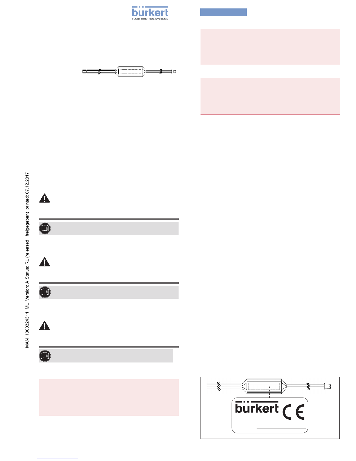
TYPE LABEL / TYPENSCHILD / PLAQUE SIGNALÉTIQUE
Code-fabricant /
Herstellercode /
Manufacturer
code
ID number /
Identnummer /
Numéro
d‘identification
689998 (A)
16/107
CE marking /
CE-Kennzeichnung /
Marquage CE
Page 2
1 INTENDED USE
2503 Boost Close is designed for use with type 6712 and type
6724 valves.
▶ Use according to the permitted data, operating conditions and
conditions of use specied in the contract documents and operating instructions.
▶ Do not use the device outdoors.
▶ The device may be used only in conjunction with third-party
devices and components recommended and authorised by
Bürkert.
▶ Correct transportation, correct storage and installation and
careful use and maintenance are essential for reliable and
problem-free operation.
▶ Use the device only as intended.
2 BASIC SAFETY INSTRUCTIONSE
These safety instructions do not consider any contingencies or incidents which occur during installation, operation and maintenance.
Risk of injury from high pressure.
▶ Before loosening the lines and valves, turn o the pressure and
vent the lines.
Risk of electric shock.
▶ Before reaching into the system, switch o the power supply and
secure to prevent reactivation.
▶ Observe applicable accident prevention and safety regulations for
electrical equipment.
Risk of burns/Risk of re if used continuously through hot device
surface.
▶ Keep the device away from highly ammable substances and media
and do not touch with bare hands.
General hazardous situations.
▶ Do not make any internal or external changes on the device and do
not subject it to mechanical stress.
▶ Secure the system from unintentional actuation.
▶ Only trained technicians may perform installation and maintenance
work.
▶ The valves must be installed in accordance with the regulations
applicable in the country.
▶ After an interruption, ensure that the process is restarted in a con-
trolled manner.
▶ Observe the general rules of technology.
3 TECHNICAL DATA
3.1 Conformity
Type 2503 conforms with the EU Directives according to the EU
Declaration of Conformity (if applicable).
3.2 Standards
The applied standards, which verify conformity with the EU Directives,
can be found on the EU-Type Examination Certicate and / or the EU
Declaration of Conformity (if applicable).
3.3 General technical data
Type 6712
Valve circuit function A
Seal material
EPDM
(not suitable for FKM and FFKM )
1)
Valve operating voltage 12…24V
Orice 0.8mm
Extended pressure range with
electronics
3)
0...6bar
Permissible return pressure /
dynamic pressure in the valve
Max. 5bar
Type 6724
Valve circuit function A, T
2)
Seal material EPDM, FKM, FFKM
Valve operating voltage 12…24V
Orice 1.2mm
Extended pressure range with
electronics
3)
Vac...7bar
Permissible return pressure /
dynamic pressure in the valve
Max. 5bar
1) with FKM and FFKM the electronics reduces the life time signicantly.
2) 3/2-way valves can be connected. In this case, the leak-tightness of the
normally closed connection (NC) is increased. The leak-tightness of the
normally open connection (NO) remains unchanged.
3) Note! If the electronics operating voltage is switched o, the pressure
values drop to the values without electronics specied in the data sheet.
4 INSTALLATION
NOTE
3/2-way valves can be connected. In this case, the leak-tightness
of ‘the normally closed’ connection (NC) is increased. The
leak-tightness of the ‘normally open’ connection (NO) remains
unchanged.
DANGER
Risk of injury from high pressure
If the operating voltage (+U
B
) is switched o (e.g. at the end of
operation or due to an emergency stop), the ‘active seal eect’
is no longer applicable. The pressure values drop to the default
values of the applied valve (see data sheet).
▶ Pay attention to the maximum permissible return pressure values
and dynamic pressure values stated in the table „3 Technical data“.
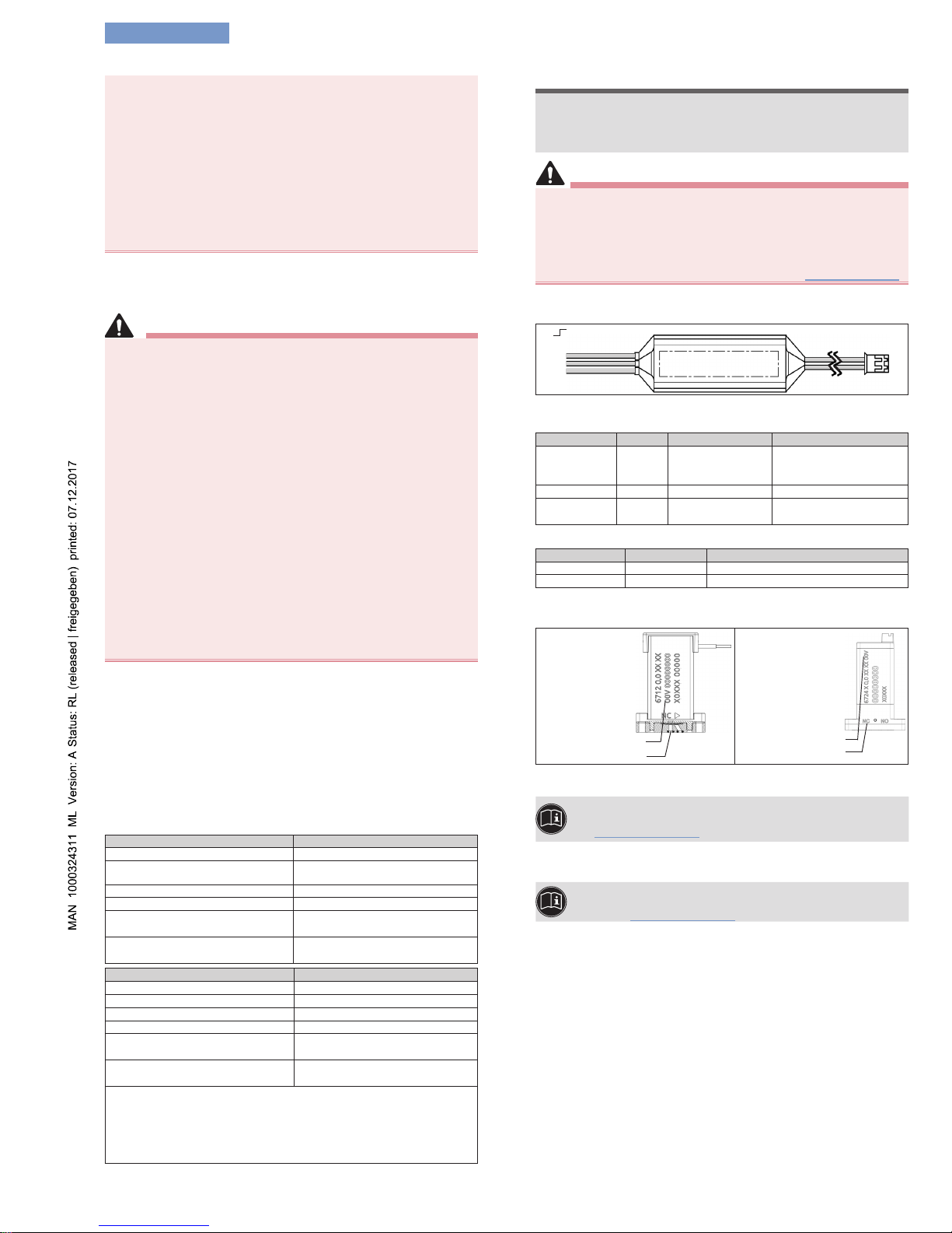
4.1 Connecting the electronics
Identication: see labeling on the electronics.
+ (red)
- (
black)
+ signal IN (gray)
GND (
black)
+U
B
(red)
Fig. 1: Connecting the valve
Input side electronics (3 wires)
Connection Color Description Voltage
+signal IN gray
Control signal
(digital)
‘low signal’ 0…+2V
‘high signal’
+5…+24V
GND black Ground 0 V
+U
B
red
Valve operating
voltage
+12…+24V
(acc. to valve imprint)
Output side electronics (2 wires, valve plug)
Connection Color Description
- black Valve connection -
+ red Valve connection +
4.2 Connecting the valve
Pressure connection at the valve inlet (NC connection):
Druckanschluss
Betriebsspannung
Betriebsspannung
Druckanschluss
Fig. 2: Connecting the valve
Installation instructions for type 6712 and type 6724 valves
can be found in the printed operating instructions or online
at: www.buerkert.com
5 DEINSTALLATION
Deinstallation instructions for type 6712 and type 6724
valves can be found in the printed operating instructions or
online at: www.buerkert.com
6 TRANSPORTATION, STORAGE, DISPOSAL
• Transport and store Type 6724 in shock-resistant packaging to
protect against moisture and dirt.
• Permitted storage temperature: –10 … +65 °C.
• Dispose of the device and packaging according to the applicable
disposal and environmental protection regulations.
Type 2503
english
Page 3

1 BESTIMMUNGSGEMÄSSER GEBRAUCH
Der Typ 2503 Boost Close ist für die Verwendung mit den Ventilen Typ 6712 oder Typ 6724 konzipiert.
▶ Für den Einsatz die in den Vertragsdokumenten und der Bedie-
nungsanleitung spezizierten zulässigen Daten, Betriebs- und
Einsatzbedingungen beachten.
▶ Das Gerät nicht im Außenbereich einsetzen.
▶ Gerät nur in Verbindung mit von Bürkert empfohlenen bzw.
zugelassenen Fremdgeräten und -komponenten einsetzen.
▶ Das Gerät nur in einwandfreiem Zustand betreiben und auf
sachgerechte Lagerung, Transport, Installation und Bedienung
achten.
▶ Das Gerät nur bestimmungsgemäß einsetzen.
2 GRUNDLEGENDE SICHERHEITSHINWEISE
Diese Sicherheitshinweise berücksichtigen keine bei Installation,
Betrieb und Wartung auftretenden, Zufälle und Ereignisse.
WARNuNG!
Verletzungsgefahr durch hohen Druck in Anlage/Gerät.
▶ Vor Arbeiten an Anlage oder Gerät, den Druck abschalten und Lei-
tungen entlüften/entleeren.
Verletzungsgefahr durch Stromschlag.
▶ Vor Arbeiten an Anlage oder Gerät, die Spannung abschalten und
vor Wiedereinschalten sichern.
▶ Die geltenden Unfallverhütungs- und Sicherheitsbestimmungen für
elektrische Geräte beachten!
Verbrennungsgefahr/Brandgefahr bei längerer Einschaltzeit durch
heiße Geräteoberäche!
▶ Das Gerät von leicht brennbaren Stoen und Medien fernhalten und
nicht mit bloßen Händen berühren.
Allgemeine Gefahrensituationen.
▶ Am Gerät keine inneren oder äußeren Veränderungen vornehmen
und nicht mechanisch belasten.
▶ Produkt oder Anlage vor ungewolltem Einschalten sichern.
▶ Nur geschultes Fachpersonal darf Installations- und Instandhal-
tungsarbeiten ausführen.
▶ Produkt gemäß der im Land gültigen Vorschriften installieren.
▶ Nach Unterbrechung der elektrischen Versorgung einen kontrol-
lierten Wiederanlauf des Prozesses sicherstellen.
▶ Die allgemeinen Regeln der Technik einhalten.
3 TECHNISCHE DATEN
3.1 Konformität
Das Produkt ist konform zu den EU-Richtlinien entsprechend der EUKonformitätserklärung (wenn anwendbar).
3.2 Normen
Die angewandten Normen, mit welchen die Konformität zu den
Richtlinien nachgewiesen wird, sind in der EU-Baumusterprüfbescheinigung und/oder der EU-Konformitätserklärung nachzulesen
(wenn anwendbar).
3.3 Allgemeine Technische Daten
Typ 6712
Ventilwirkungsweise A
Dichtwerksto EPDM
(nicht geeignet für FKM und
FFKM )
1)
Ventilbetriebsspannung 12…24V
Nennweite 0,8mm
Erweiterter Druckbereich mit
Elektronik
3)
0...6bar
Zulässiger Rückdruck / Staudruck im Ventil
max. 5bar
Typ 6724
Ventilwirkungsweise A, T
2)
Dichtwerksto EPDM, FKM, FFKM
Ventilbetriebsspannung 12…24V
Nennweite 1,2mm
Erweiterter Druckbereich mit
Elektronik
3)
Vak...7bar
Zulässiger Rückdruck /Staudruck im Ventil
max. 5bar
1) bei FKM und FFKM führt die Elektronik zu einer deutlichen Reduzierung
der Lebensdauer.
2) Der Anschluss von 3/2-Wege Ventilen ist möglich. In diesem Fall, wird
nur die Dichtheit des Normally-Closed Anschlusses (NC) erhöht. Die
Dichtheit des Normally-Open Anschlusses (NO) bleibt unverändert.
3) Achtung! Wird die Betriebsspannung der Elektronik abgeschaltet,
reduzieren sich die Druckwerte wieder auf die im Datenblatt angegebenen
Werte ohne Elektronik.
4 INSTALLATION
AchTuNG
Der Anschluss von 3/2-Wege Ventilen ist möglich. In diesem
Fall, wird nur die Dichtheit des „Normally-Closed“-Anschlusses
(NC) erhöht. Die Dichtheit des „Normally-Open“-Anschlusses
(NO) bleibt unverändert.
GEfAhR!
Verletzungsgefahr durch hohen Druck
Wird die Betriebsspannung (+U
B
) abgeschaltet (z.B. durch
Betriebsende oder Notaus), entfällt die „aktive Dichtwirkung“.
Die Druckwerte sinken, auf die Standardwerte des verwendeten
Ventils (siehe Datenblatt).
▶ Maximal zulässige Rückdruckwerte und Staudruckwerte laut
Tabelle „3 Technische Daten“beachten.
4.1 Anschluss der Elektronik
Kennzeichnung: siehe Beschriftung auf der Elektronik.
+ (rot)
- (schwarz)
+ Signal IN (grau)
GND (schwarz)
+U
B
(rot)
Bild 1: Anschluss des Ventils
Elektronik Eingangsseite (3 Litzen)
Anschluss Farbe Beschreibung Spannung
+Signal IN grau Steuersignal (digital)
„low-Signal“
0…+2V
„high-Signal“
+5…+24V
GND schwarz Ground 0V
+U
B
rot
Betriebsspannung für
Ventil
+12…+24V
(lt. Ventilaufdruck)
Elektronik Ausgangsseite (2 Litzen, Ventilstecker)
Anschluss Farbe Beschreibung
- schwarz Ventilanschluss + rot Ventilanschluss +
4.2 Anschluss des Ventils
Druckanschluss am Ventileingang (NC- Anschluss):
Druckanschluss
Betriebsspannung
Betriebsspannung
Druckanschluss
Bild 2: Anschluss des Ventils
Installationshinweise zu den Typen 6712 und 6724 nden
Sie in der gedruckten Bedienungsanleitung oder im Internet
unter: www.buerkert.de
5 DEINSTALLATION
Deinstallationshinweise zu den Typen 6712 und 6724
nden Sie in der gedruckten Bedienungsanleitung oder im
Internet unter: www.buerkert.de
6 TRANSPORT, LAGERUNG, ENTSORGUNG
• Typ 2503 vor Nässe und Schmutz geschützt in einer stoßfesten
Verpackung transportieren und lagern.
• Zulässige Lagertemperatur: –10 … +65 °C.
• Bei der Entsorgung von Gerät und Verpackung die geltenden Ent-
sorgungsvorschriften und Umweltbestimmungen einhalten.
Typ 2503
deutsch
Page 4

1 UTILISATION CONFORME
Le type 2503 Boost Close est conçu pour être utilisé avec les
vannes types 6712 et 6724.
▶ Lors de l’utilisation, il convient de respecter les données et condi-
tions d’utilisation et d’exploitation admissibles spéciées dans les
instructions de service et dans les documents contractuels.
▶ Ne pas utiliser l’appareil à l’extérieur.
▶ L’appareil peut être utilise uniquement en association avec les
appareils et composants étrangers recommandés et homologués par Bürkert.
▶ Les conditions pour l’utilisation sûre et parfaite sont un
transport, un stockage et une installation dans les règles ainsi
qu’une parfaite utilisation et maintenance.
▶ Veillez à ce que l’utilisation de l’appareil soit toujours conforme.
2 CONSIGNES DE SÉCURITÉ FONDAMENTALES
Ces consignes de sécurité ne tiennent pas compte des hasards et
des événements pouvant survenir lors du montage, de l‘exploitation
et de l‘entretien.
Risque de blessures dû à la haute pression.
▶ Avant d‘intervenir dans l‘installation ou l‘appareil, couper la pres-
sion et désaérer ou vider les conduites.
Verletzungsgefahr durch Stromschlag.
▶ Avant d‘intervenir dans l‘installation ou l‘appareil, couper la tension
et empêcher toute remise sous tension par inadvertance.
▶ Veuillez respecter les réglementations en vigueur pour les appareils
électriques en matière de prévention des accidents ainsi qu’en
matière de sécurité.
Risque de brûlures et d‘incendie lors d‘une durée de
fonctionnement
prolongée dû à la surface brûlante de l‘appareil.
▶ Tenez les substances et les uides facilement inammables à
l‘écart de l‘appareil et ne touchez pas ce dernier à mains nues.
Situations dangereuses d‘ordre général.
▶ Ne pas entreprendre de modications internes ou externes sur
l‘appareil et ne pas l‘exposer à des sollicitations mécaniques.
▶ Protéger l‘appareil contre toute mise en marche involontaire.
▶ Seul du personnel qualié peut eectuer l‘installation et la
maintenance.
▶ Les vannes doivent être installées conformément à la réglementa-
tion en vigueur dans le pays respectif.
▶ Garantir un redémarrage contrôlé du processus après une
interruption.
▶ Respecter les règles générales de la technique.
3 CARACTÉRISTIQUES TECHNIQUES
3.1 Conformité
Le type 2503 est conforme aux directives UE comme stipulé dans la
déclaration de conformité UE (si applicable).
3.2 Normes
Les normes appliquées justiant la conformité aux directives UE
peuvent être consultées dans l‘attestation d‘examen UE de type et /
ou la déclaration de conformité UE (si applicable).
3.3 Caractéristiques techniques générales
Type 6712
Fonction de la vanne A
Matériau du joint
EPDM (ne convient pas
pour FKM et FFKM )
1)
Tension de service de la vanne 12…24 V
Diamètre nominal 0,8mm
Plage de pression étendue avec
électronique
3)
0...6 bars
Pression de retour / pression dynamique
admise dans la vanne
max. 5 bars
Type 6724
Fonction de la vanne A, T
2)
Matériau du joint EPDM, FKM, FFKM
Tension de service de la vanne 12…24 V
Diamètre nominal 1,2mm
Plage de pression étendue avec
électronique
3)
Vide...7bars
Pression de retour / pression dynamique
admise dans la vanne
max. 5 bars
1) pour FKM et FFKM, l’électronique entraîne une réduction signicative de
la durée de vie.
2) Possibilité de raccorder des vannes à 3/2voies. Dans ce cas, seule
l'étanchéité du raccord Normally-Closed (NC) est augmentée. L’étanchéité
du raccord Normally-Open (NO) reste inchangée.
3) Remarque! Si la tension de service de l’électronique est coupée, les
valeurs de pression retombent aux valeurs sans module électronique indiquées dans la che technique.
4 INSTALLATION
REMARQuE
Possibilité de raccorder des vannes à 3/2voies. Dans ce cas,
seule l‘étanchéité du raccord «Normally-Closed» (NC) est augmentée. L’étanchéité du raccord «Normally-Open» (NO) reste
inchangée.
DANGER
Risque de blessure dû à une pression élevée
Si la tension de service (+U
B
) est coupée (p. ex. à la n du service
ou par un arrêt d’urgence), il n’y a pas de «mode étanche actif».
Les valeurs de pression retombent aux valeurs standard de la
vanne utilisée (voir che technique).
▶ Respecter les valeurs de pression de retour et de pression dyna-
mique maximales admises suivant le tableau „3 Caractéristiques
techniques“ .
4.1 Raccordement de l’électronique
Identication: voir marquage sur le module électronique.
+ (rouge)
- (noir)
+ Signal IN (gris)
GND (noir)
+U
B
(rouge)
Fig. 1 : Raccordement de la vanne
Côté entrée électronique (3torons)
Raccord Couleur Description Tension
+Signal
IN
gris
Signal de
commande
(numérique)
«Signal Low» 0… +2V
«Signal High»
+5…+24V
GND noir Ground 0V
+U
B
rouge
Tension de
service pour la
vanne
+12…+24V
(selon étiquette sur la
vanne)
Côté sortie électronique (2torons, connecteur de vanne)
Raccord Couleur Description
- noir Raccord de vanne + rouge Raccord de vanne +
4.2 Raccordement de la vanne
Raccord de pression à l’entrée de la vanne (raccord NC):
Raccord de pression
Tension de service
Tension de service
Raccord de pression
Fig. 2 : Raccordement de la vanne
Vous trouverez les instructions d’installation des types
6712 et 6724 dans la version imprimée du manuel
d'utilisation ou sur Internet: www.buerkert.fr
5 DÉSINSTALLATION
Vous trouverez les instructions de désinstallation des
types 6712 et 6724 dans la version imprimée du manuel
d‘utilisation ou sur Internet: www.buerkert.fr
6 TRANSPORT, STOCKAGE, ÉLIMINATION
• Transporter et stocker le type 2503 à l‘abri de l‘humidité et des
impuretés et dans un emballage résistant aux chocs.
• Température de stockage autorisée : –10...+65°C.
• Lors de l‘élimination de l‘appareil et de l‘emballage, respecter les
prescriptions en matière d’élimination des déchets et de protection de l’environnement en vigueur.
Type 2503
francais
 Loading...