

Page 1
Type 8635
Remote-Positioner
Installation on process valves with internal air flow (series 2103, 2300, 2301)
Anbau an Prozessventile mit interner Luftführung (Reihe 2103, 2300, 2301)
Intégration sur des vannes de process dotées d'un système interne de guidage d'air
(séries 2103, 2300, 2301)
Zusatzanleitung
English Deutsch Français
Page 2
Type 8635, Remote-Positioner
Additional instructions
Contents
1 ADDITIONAL INSTRUCTIONS .............................................. 2
1.1 Symbols ....................................................................... 2
2 REMOTE OPERATION .......................................................... 3
3 ASSEMBLING THE POSITION SENSOR .............................. 4
3.1 Installing attachment kit on the actuator ..................... 4
3.2 Mounting remote position sensor on the actuator ...... 5
3.3 Pneumatic connection of the position sensor ............. 7
3.4 Electrical connection of the position sensor ............... 8
4 START-UP .............................................................................. 9
5 REMOVAL ............................................................................ 10
5.1 Removing the position sensor ................................... 10
6 TRANSPORTATION, STORAGE, DISPOSAL ...................... 11
1 ADDITIONAL INSTRUCTIONS
The additional instructions describe the installation and start-up
of the remote positioner for process valves with internal air ow
(series 2103, 2300, 2301).
Important safety information.
▶ Carefully read these instructions.
▶ Observe in particular the safety instructions, intended use,
and the operating conditions.
▶ Persons, who work on the device, must read and understand
these instructions.
The operating instructions for the process valves can be
found on the Internet at: www.burkert.com
1.1 Symbols
▶ Highlights instructions to avoid a danger.
→ Designates a procedure which you must carry out.
Warning of injuries:
DANGER!
Immediate danger! Serious or fatal injuries.
WARNING!
Possible danger! Serious or fatal injuries.
CAUTION!
Danger! Moderate or minor injuries.
NOTE!
(Warning of damage)
▶ Highlights instructions to avoid a danger.
→ Designates a procedure which you must carry out.
english
2
Page 3
Type 8635, Remote-Positioner
Remote operation
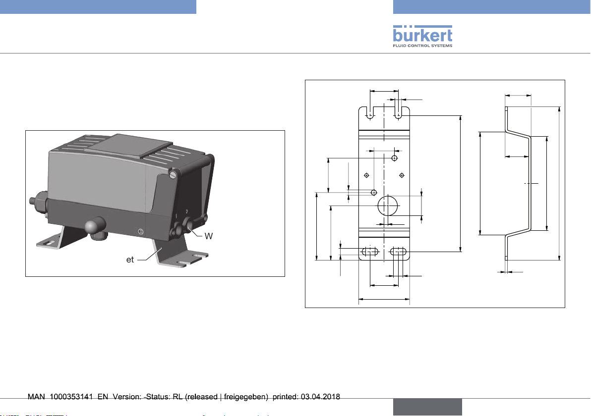
2 REMOTE OPERATION
In the case of remote operation, the positioner has no position
sensor in the form of a rotary position sensor, but is connected to
an external position sensor. The 2.5 m long connection cable is
pre-assembled on the positioner.
Working port 2
Mounting bracket
Fig. 1: Remote positioner with mounting bracket
2.1.1 Mounting accessories
The pre-assembled mounting bracket can be used to attach
Type 8635 in remote operation.
2.1.2 Dimensions
36
8.5
26.2
44
ø 6.8
ø 25
4.5
86.5
69.5
8.5
36
65
Fig. 2: Dimensions of the mounting bracket
12
174
131.5
33
30
3
120
196.1
english
3
Page 4
Type 8635, Remote-Positioner
Assembling the position sensor
3 ASSEMBLING THE POSITION
SENSOR
DANGER!
Risk of injury from high pressure and discharge of medium.
▶ Before working on the device or system, switch o the pres-
sure. Vent or drain lines.
Risk of injury from electric shock.
▶ Before working on the device or system, switch o the power
supply. Secure against reactivation.
WARNING!
Risk of injury due to incorrect assembly.
▶ Assembly may be carried out only by authorized specialist
personnel and using the appropriate tools.
Risk of injury due to unintentional switching on of the plant
and uncontrolled start-up.
▶ Secure system against unintentional activation.
▶ Following assembly, ensure a controlled restart.
CAUTION!
Risk of injury due to heavy device.
A heavy device can fall down and cause injury during transport
or assembly work.
▶ Do not transport, install or remove a heavy device without the
aid of a second person.
▶ Use suitable auxiliary tools.
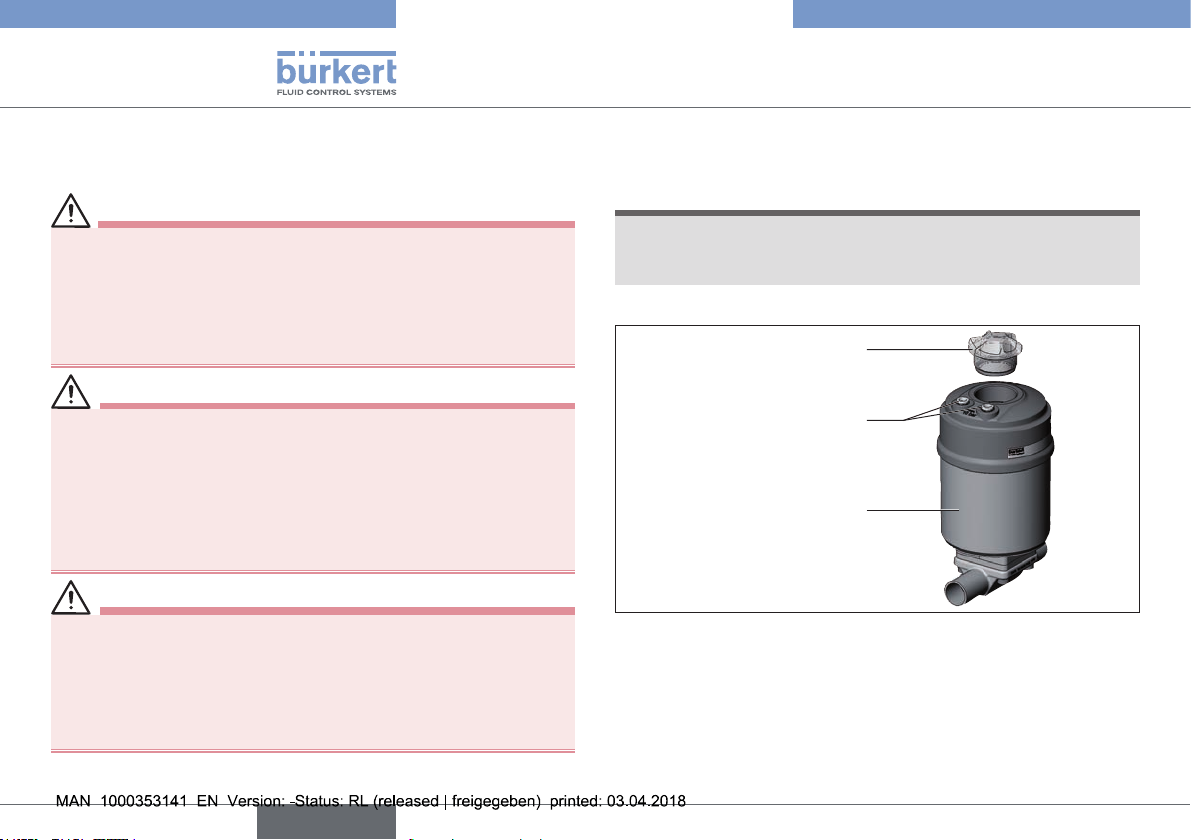
3.1 Installing attachment kit on the actuator
NOTE!
To install process valves with welded body, follow the
installation instructions in the operating instructions for the
process valve.
1. Assembling switch spindle
Transparent cap
Pilot air ports
(push-in connectors with
collets or thr
Fig. 3: Assembling switch spindle
→ Unscrew the transparent cap on the actuator and the position
indicator (yellow cap) on the spindle extension (if present).
→ For version with push-in connector, remove the collets (white
nozzles) from both pilot air ports (if present).
eaded bushings)
Actuator
4
english
Page 5

Type 8635, Remote-Positioner
Assembling the position sensor
NOTE!
Improper assembly may damage the lip seal in the guide
element.
The lip seal is pre-mounted in the guide element and must be
"locked into position" in the undercut.
▶ When assembling the switch spindle, do not damage the lip
seal.
→ Slide switch spindle through guide element.
→ To secure the switch spindle, apply a little screw locking paint
(Loctite 290) to the thread of the switch spindle.
→ Screw guide element into the actuator cover. Ensure that the
O-ring is positioned in the actuator cover.
→ Tighten guide element to 5Nm.
→ Tighten switch spindle using a at-tip screwdriver, maximum
torque 1Nm.
2. Install sealing rings
→ Pull the form seal onto the actuator cover (smaller diameter
points upwards).
→ Check that the O-rings are correctly positioned in the pilot air
ports.
When the remote sensor is being installed, the collets of
the pilot air ports must not be tted to the actuator.
Switch cam
Switch spindle complete
Guide element
Form seal
Fig. 4: Actuator with installed switch spindle
3.2 Mounting remote position sensor on the actuator
→ Unscrew body casing from the position sensor in a counter-
clockwise direction and remove.
Body casing
Connection housing
Fig. 5: Remote position sensor
english
5
Page 6

→ Push potentiometer slide downwards.
Slide
Potentiometer
Fig. 6: Inserting slide into switch cam
Switch cam
→ Insert slide sideways into the switch cam; in doing so,
connect the housing of the position sensor to the actuator
and align.
NOTE!
▶ The potentiometer slide must be hooked into the switch
cam.
▶ Align the connection pieces of the position sensor with the
pilot air ports.
Type 8635, Remote-Positioner
Assembling the position sensor
Switch cam with attached
slide
Connection piece of the
position sensor
Pilot air ports of the actuator
Fig. 7: Aligning position sensor with the actuator
→ Push position sensor without turning it onto the actuator until
no gap is visible on the form seal.
6
english
Form seal
Fig. 8: Actuator with attached position sensor
Page 7

Type 8635, Remote-Positioner
Assembling the position sensor
Fastening screws
(2x)
Fig. 9: Attachment of the position sensor
NOTE!
Observe tightening torque when attaching the position
sensor.
If the fastening screws are tightened too tightly, the degree of
protection IP65 and IP 67 is no longer guaranteed.
▶ Tighten the fastening screws to a maximum tightening
torque of 1.5 Nm.
→ Attach position sensor to the actuator using the two side
fastening screws. Observe maximum tightening torque
of 1.5 Nm.
3.3 Pneumatic connection of the position sensor
DANGER!
Risk of injury from high pressure and discharge of medium.
▶ Before working on the device or system, switch o the pres-
sure. Vent or drain lines.
Port 1
Port 3:
not used, internally sealed
Port 3
1
Fig. 10: Pneumatic connection
english
7
Page 8

Type 8635, Remote-Positioner
Assembling the position sensor
Length of the pilot air line:
The length of the pilot air line should be adjusted to the
actuator size. The dead space volume which occurs
due to the pilot air line may negatively aect the control
characteristics.
In principle, the following applies: the smaller the actuator,
the more sensitively the control system reacts to the
length of the pilot air line.
Procedure for single-actuating actuators, control function A
and B:
→ Connect working port 2 of the positioner Type 8635 via a
hose to port 1.
Working port 2, see "Fig. 1".
→ Fit exhaust air line or a silencer to port 31.
The applied supply pressure must be 0.5 to 1 bar greater than
the minimum control pressure specied on the control valve. This
ensures that the control behavior is not very negatively aected in
the upper stroke range due to too little pressure dierence.
During operation keep the uctuations of the supply pressure low
(max. ±10 %). If uctuations are greater, the control parameters
measured with the X.TUNE function are not optimal.
3.4 Electrical connection of the position sensor
DANGER!
Danger due to electrical shock.
▶ Switch o the power supply and secure it against reactivation.
→ Feed the cable of the positioner (with at plug tted) through
the cable gland of the position sensor.
→ Connect the 3-pin at plug of the positioner to the coun-
terpart of the potentiometer.
3-pin at plug
Cable gland of the
position sensor
Fig. 11: Electrical connection
8
english
Page 9

Type 8635, Remote-Positioner
Start-up
→ When tightening the cable gland, note the position of the
plug-in connection. See marked area in the following "Fig. 12".
NOTE!
The cable in the housing must have a minimum length, but
must not be under tension.
Plug-in
connection must
be within the
marked area.
Fig. 12: Position of the electrical plug-in connection for position con-
troller and position sensor
4 START-UP
WARNING!
Risk of injury due to incorrect operation.
▶ Prior to start-up, make sure operating personnel are familiar
with the operating instructions and have understood them.
▶ The device or system should be started up by fully trained
personnel only.
Risk of injury due to unintentional switching on of the plant
and uncontrolled start-up.
▶ Secure system against unintentional activation.
▶ Following assembly, ensure a controlled restart.
→ Connect compressed air to the positioner.
→ Connect positioner pneumatically to the position sensor.
→ Switch on the operating voltage of Type 8635.
→ Run the X.TUNE function.
→ Attach body casing and screw in clockwise all the way.
english
9
Page 10

Type 8635, Remote-Positioner
Removal
5 REMOVAL
DANGER!
Risk of injury from high pressure and discharge of medium.
▶ Before working on the device or system, switch o the pres-
sure. Vent or drain lines.
Risk of injury from electric shock.
▶ Before working on the device or system, switch o the power
supply. Secure against reactivation.
▶ Observe applicable accident prevention and safety regula-
tions for electrical equipment.
WARNING!
Risk of injury due to improper disassembly.
▶ Removal should be performed only by trained personnel
using suitable tools.
Risk of injury from hazardous media.
▶ Before loosening lines or valves, ush out hazardous media,
depressurize and drain the lines.
CAUTION!
Risk of injury due to heavy device.
A heavy device can fall down and cause injury during transport
or assembly work.
▶ Do not transport, install or remove a heavy device without the
aid of a second person.
▶ Use suitable auxiliary tools.
5.1 Removing the position sensor
→ Disconnect the pneumatic connections.
→ Switch o the power supply and secure it against reactivation.
→ Unscrew body casing by rotating it in a counterclockwise
direction.
3-pin at plug
Cable gland of the
position sensor
Fig. 13: Removing electrical connection
→ Disconnect 3-pin at plug from the counterpart of the
potentiometer.
→ Feed positioner cable outwards through the cable gland.
Fastening screws
(2x)
Fig. 14: Position sensor fastening screws
→ Loosen side fastening screws.
10
english
Page 11

Type 8635, Remote-Positioner
Transportation, storage, disposal
Slide
Switch cam
Position sensor
Actuator
Fig. 15: Removing position sensor
→ Slightly raise position sensor housing and tilt it to the side to
move the slide away from the switch cam.
→ Remove position sensor from the actuator.
6 TRANSPORTATION, STORAGE,
DISPOSAL
CAUTION!
Risk of injury due to heavy device.
A heavy device can fall down and cause injury during transport
or assembly work.
▶ Do not transport, install or remove a heavy device without the
aid of a second person.
▶ Use suitable auxiliary tools.
NOTE!
Damage in transit due to inadequately protected devices.
• Protect the device against moisture and dirt in shock-
resistant packaging during transportation.
• Observe permitted storage temperature.
Incorrect storage may damage the device.
• Store the device in a dry and dust-free location.
• Storage temperature. -25…+65°C
Damage to the environment caused by device components
contaminated with media.
• Dispose of the device and packaging in an environmentally
friendly manner.
• Observe applicable disposal and environmental regulations.
english
11
Page 12

We reserve the right to make technical changes without notice.
Technische Änderungen vorbehalten.
Sous réserve de modifications techniques.
© Bürkert Werke GmbH & Co. KG, 2018
Operating Instructions 1803/00_EU-ML_00810707 / Original DE
www.burkert.com
 Loading...