

Burkert 2300 User Manual [en, de, fr]
Type 2300
2/2-way angle-seat control valve
2/2-Wege Schrägsitzregelventil
Vanne de réglage à siège incliné 2/2 voies
Quickstart
English Deutsch Français
We reserve the right to make technical changes without notice.
Technische Änderungen vorbehalten.
Sous réserve de modifications techniques.
© Bürkert Werke GmbH, 2013
Operating Instructions 1309/01_EU-ML_00810317 / Original DE
Typ 2300
Quickstart
1. QUICKSTART .....................................................................................................3
2. SYMBOLS
3. INTENDED USE ................................................................................................4
4. BASIC SAFETY INSTRUCTIONS .............................................................5
5. GENERAL INFORMATION ...........................................................................6
6. STRUCTURE AND FUNCTION..................................................................6
7. TECHNICAL DATA ...........................................................................................7
8. INSTALLATION
9. PACKAGING, TRANSPORT, STORAGE .............................................15
............................................................................................................4
..................................................................................................9
1. QUICKSTART
The operating instructions describe the entire life cycle of the device.
Keep these instructions in a location which is easily accessible to
every user and make these instructions available to every new owner
of the device.
Important Safety Information!
Read Quickstart carefully and thoroughly. Study in particular the
chapters entitled “Basic Safety Instructions” and “Intended use”.
• Quickstart must be read and understood.
Quickstart explains, for example, how to install and start-up the
device.
A detailed description of the device can be found in the operating
instructions for Type 2300.
The operating instructions can be found on the Internet at:
www.burkert.com
1.1. Definition of term / abbreviation
In these instructions, the term “device” always refers to the angleseat control valve type 2300.
The abbreviation “Ex” used in these instructions always stands for
“explosion-protected”.
english
3
Typ 2300
Symbols
2. SYMBOLS
DANGER!
Warns of an immediate danger!
• Failure to observe the warning may result in a fatal or serious
injury.
WARNING!
Warns of a potentially dangerous situation!
• Failure to observe the warning may result in serious injuries or
death.
CAUTION!
Warns of a possible danger!
• Failure to observe this warning may result in a moderately severe
or minor injury.
NOTE!
Warns of material damage!
Important tips and recommendations.
Refers to information in these operating instructions or in
other documentation.
3. INTENDED USE
Non-intended use of the angle-seat control valve Type 2300 may
be a hazard to people, nearby equipment and the environment.
• The device is designed for the controlled flow of liquid and
gaseous media. Operation is possible only in combination with a
suitable control unit.
• The admissible data, the operating conditions and conditions of
use specified in the contract documents, operating instructions
and on the type label are to be observed during use. These are
described in the chapter entitled “Technical data”.
• The device may be used only in conjunction with third-party
devices and components recommended and authorised by
Bürkert.
• Correct transportation, correct storage and installation and
careful use and maintenance are essential for reliable and faultless operation.
• Use the device only as intended.
3.1. Restrictions
If exporting the system/device, observe any existing restrictions.
→ designates a procedure which you must carry out.
4
english
Typ 2300
Basic Safety Instructions
4. BASIC SAFETY INSTRUCTIONS
These safety instructions do not make allowance for any
• contingencies and events which may arise during the installation,
operation and maintenance of the devices.
• local safety regulations; the operator is responsible for observing
these regulations, also with reference to the installation personnel.
Danger – high pressure!
• Before loosening the lines and valves, turn off the pressure and
vent the lines.
Risk of electric shock!
• Before reaching into the device, switch off the power supply
and secure to prevent reactivation!
• Observe applicable accident prevention and safety regulations
for electrical equipment!
Risk of burns!
The surface of the device may become hot during long-term
operation.
• Do not touch the device with bare hands.
Risk of injury from moving parts in the device!
• Do not reach into openings.
Risk of injury when opening the actuator!
The actuator contains a tensioned spring. If the actuator is opened,
there is a risk of injury from the spring jumping out.
• The actuator must not be opened.
General hazardous situations.
To prevent injury, ensure that:
• The system cannot be activated unintentionally.
• Installation and repair work may be carried out by authorised
technicians only and with the appropriate tools.
• After an interruption in the power supply or pneumatic supply,
ensure that the process is restarted in a defined or controlled
manner.
• The device may be operated only when in perfect condition and
in consideration of the operating instructions.
• The general rules of technology apply to application planning
and operation of the device.
• In the potentially explosion-risk area the angle-seat control valve
Type 2300 may be used only according to the specification on
the separate Ex type label. For use observe the additional information enclosed with the device together with safety instructions for the explosion-risk area.
• Devices without a separate Ex type label may not be used in a
potentially explosive area.
To prevent damage to property of the device, ensure:
• Supply the media connections only with those media which are
specified as flow media in the chapter entitled “Technical data”.
• Do not put any loads on the valve (e.g. by placing objects on it
or standing on it).
• Do not make any external modifications to the valves. Do not paint
the body parts or screws.
english
5
Typ 2300
P
A
General Information
5. GENERAL INFORMATION
5.1. Contact addresses
Germany
Bürkert Fluid Control Systems
Sales Centre
Christian-Bürkert-Str. 13-17
D-74653 Ingelfingen
Tel. + 49 (0) 7940 - 10 91 111
Fax + 49 (0) 7940 - 10 91 448
E-mail: info@de.buerkert.com
International
Contact addresses are found on the Internet under:
www.burkert.com
5.2. Warranty
The warranty is only valid if the device is used as authorized in accordance with the specified application conditions.
5.3. Information on the internet
The operating instructions and data sheets for Type 2300 can be found
on the Internet at: www.burkert.com
6. STRUCTURE AND FUNCTION
The angle-seat control valve Type 2300 can be operated
only in combination with the following control units:
Positioner Type 8692, 8694, 8696 and 8792;
Process controller Type 8693 and 8793.
6.1. Structure
The valve seats are incorporated directly. Via a dowel pin, the control
cone is modularly coupled to the actuator spindle for quick changeovers. The flow direction is always below seat.
6.2. Function
The seat of the valve is always closed against the medium flow.
Spring force (CFA) or pneumatic pilot pressure (CFB and CFI) generates the closing force on the control cone. The force is transferred
via a spindle which is connected to the actuator piston.
6.2.1. Control functions (CF)
WARNING!
For control function I – Danger if pilot pressure fails!
For control function I control and resetting occur pneumatically. If
the pressure fails, no defined position is reached.
• To ensure a controlled restart, first pressurize the device with pilot
pressure, then switch on the medium.
A
Normally closed by spring action
6
english
Typ 2300
A
Technical data
B
I
Normally open by spring action
P
A
Actuating function via reciprocal pressurization
P
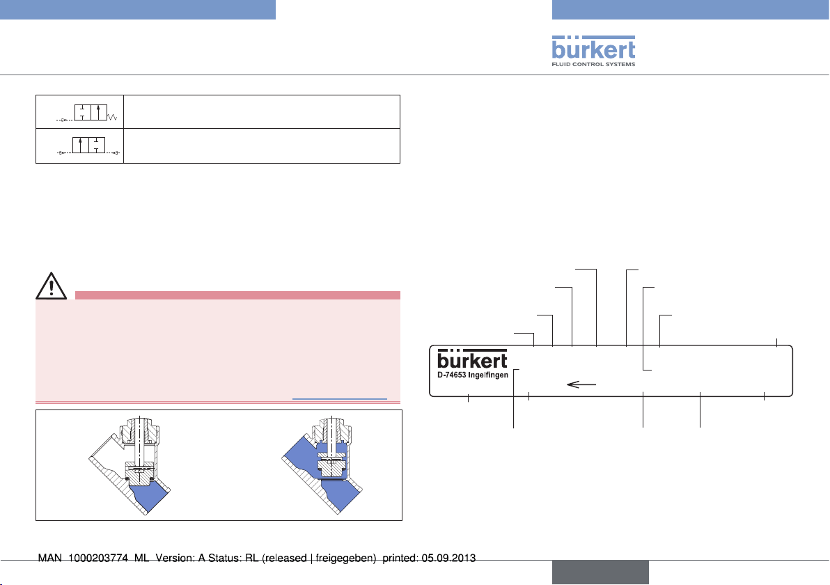
6.2.2. Flow direction below the seat
Depending on the version, the valve is closed against the medium
flow with spring force (control function A, CFA) or with pilot
pressure (control function B or I, CFB or CFI).
As the medium pressure is under the control cone, this pressure
contributes to the opening of the valve.
WARNING!
Medium may be discharged if minimum pilot pressure is too
low or medium pressure too high!
If the minimum pilot pressure is too low for CFB and CFI or the
permitted medium pressure is exceeded, leaks may occur.
• Observe minimum pilot pressure.
• Do not exceed medium pressure (see chapter “Pressure ranges”).
CFA CFB / CFI
7. TECHNICAL DATA
7.1. Conformity
Type 2300 conforms with the EC Directives according to the EC
Declaration of Conformity.
7.2. Standards
The applied standards, which verify conformity with the EC Directives,
can be found on the EC Type Examination Certificate and / or the EC
Declaration of Conformity.
7.3. Type label
Sealing material
Orifice of the seat /
actuator size
Control function (CF)
Type
2300 A 25M PTFE VA
Tmed -10°C - +185°C
00203496
Flow 1 2
Identification
number
Permitted medium
temperature
Flow direction
Main dimensions of
line connection
Body material
Permitted medium
pressure
Permitted pilot pressure
CE identification
Pilot 5,5-7bar
Pmed 16,0bar
G1" Kvs16,0
manufacture
Flow capacity in standard
production conditions
CE
W3ZLT
Date of
Fig. 1: Flow direction below the seat
(Rest open/closed, closing against medium)
english
7
Typ 2300
Technical data
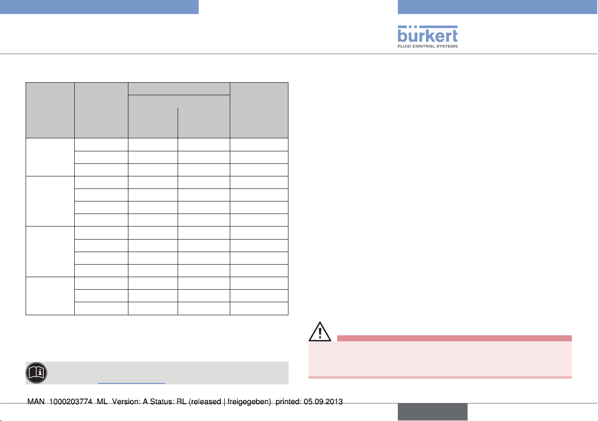
7.4. Operating conditions
Observe permitted ranges on the type label of the device!
7.4.1. Temperature ranges
Actuator
size
[mm]
Actuator
material
ø 50
ø 70
ø 90
PPS
ø 130
Tab. 1: Temperature ranges
1)
If a pilot valve/control unit is used, the max. ambient
temperature is +55 °C.
The angle-seat control valve is suitable for steam
sterilization.
2)
Pilot air ports with push-in connector
3)
Pilot air ports with threaded bushing
Medium
Seat seal
steel - steel
-10 ...
+185 °C
Seat seal
PTFE - steel
-10 ...
+130 °C
Environment
0 ...
+60 °C
0 ...
+100 °C
2)
3)
7.4.2. Control medium
In conjunction with pneumatic control units (positioner and process
controllers), pilot air according to DIN ISO 8573-1 must be used:
• Class 3 (for water content),
• Class 5 (for dust and oil content).
The specification is described in detail in the operating
1)
instructions of the respective positioner / process controller
in the chapter entitled “Technical data”.
7.4.3. Pressure ranges
Maximum pilot pressure for valves without pneumatic control units
Actuator size [mm] Actuator material
Max. permitted
pilot pressure
ø 50
10 barø 70
ø 90
PPS
ø 130 7 bar
Tab. 2: Pilot pressure for valves without pneumatic control units
4)
Observe the maximum pressure range according to the
type label!
Minimum control pressure P
Actuator size
50 / 70 / 90 130
[mm]
P
[bar] 5.5 5.5 5.6
min
Tab. 3: Minimum control pressure for CFA
for control function A
min
(Connection size
DN40 and DN50)
4)
130
(Connection size
DN65)
8
english
Typ 2300
Technical data
Pilot pressure for control function B
Pilot pressure [bar] Max. per-
Actuator
size
ø 50 mm
ø 70 mm
ø 90 mm
ø 130 mm
Tab. 4: Pilot pressure for control function B
The required minimum pilot pressure P
I (flow below the seat) is dependent on the pressure of the medium.
Connection
size [mm]
15 4.6 6.6 16
20 5.1 7.0 9
25 5.1 7.0 5
15 4.4 5.3 16
20 5.2 6.8 16
25 5.2 7.0 12
32 5.2 7.0 6
25 2.4 4.2 16
32 2.4 5.3 16
40 2.5 6.5 16
50 2.5 7.0 14
40 2.7 4.5 16
50 2.7 5.6 16
65 2.7 7.0 16
The pressure diagrams are in the operating instructions on
the Internet: www.burkert.com
for medium pressure
0 bar max
with control function B and
min
mitted
medium
pressure
[bar]
7.5. General technical data
Media
Control medium neutral gases, air
Flow media Water, Alcohol, Fuel, Hydraulic liquids,
Saline solutions, Lyes, Organic solvents
Installation position as required, preferably with actuator in
upright position
Protection class IP67 in accordance with
IEC 529/EN 60529
Control functions (CF) The valve seat is always closed against the
medium flow
Control function A Normally closed by spring action
Control function B Normally open by spring action
Control function I Actuating function via reciprocal pressur-
ization (not for actuator size ø 50 mm in
combination with Type 8696)
8. INSTALLATION
8.1. Safety instructions
DANGER!
Danger – high pressure in the equipment!
• Before loosening the lines and valves, turn off the pressure and
vent the lines.
english
9
Typ 2300
Technical data
WARNING!
Risk of injury from improper installation!
• Installation may be carried out by authorised technicians only and
with the appropriate tools!
Risk of injury from unintentional activation of the system and
an uncontrolled restart!
• Secure system from unintentional activation.
• Following assembly, ensure a controlled restart.
For control function I – Danger if pilot pressure fails!
For control function I control and resetting occur pneumatically.
If the pressure fails, no defined position is reached.
• To ensure a controlled restart, first pressurize the device with pilot
pressure, then switch on the medium.
Risk of injury from moving parts in the device!
• Do not reach into openings.
8.2. Before installation
• The globe control valve can be installed in any installation position,
preferably with the actuator in upright position.
• Before connecting the valve, ensure the pipelines are flush.
• Make certain the flow direction is correct (flow direction always
below the seat).
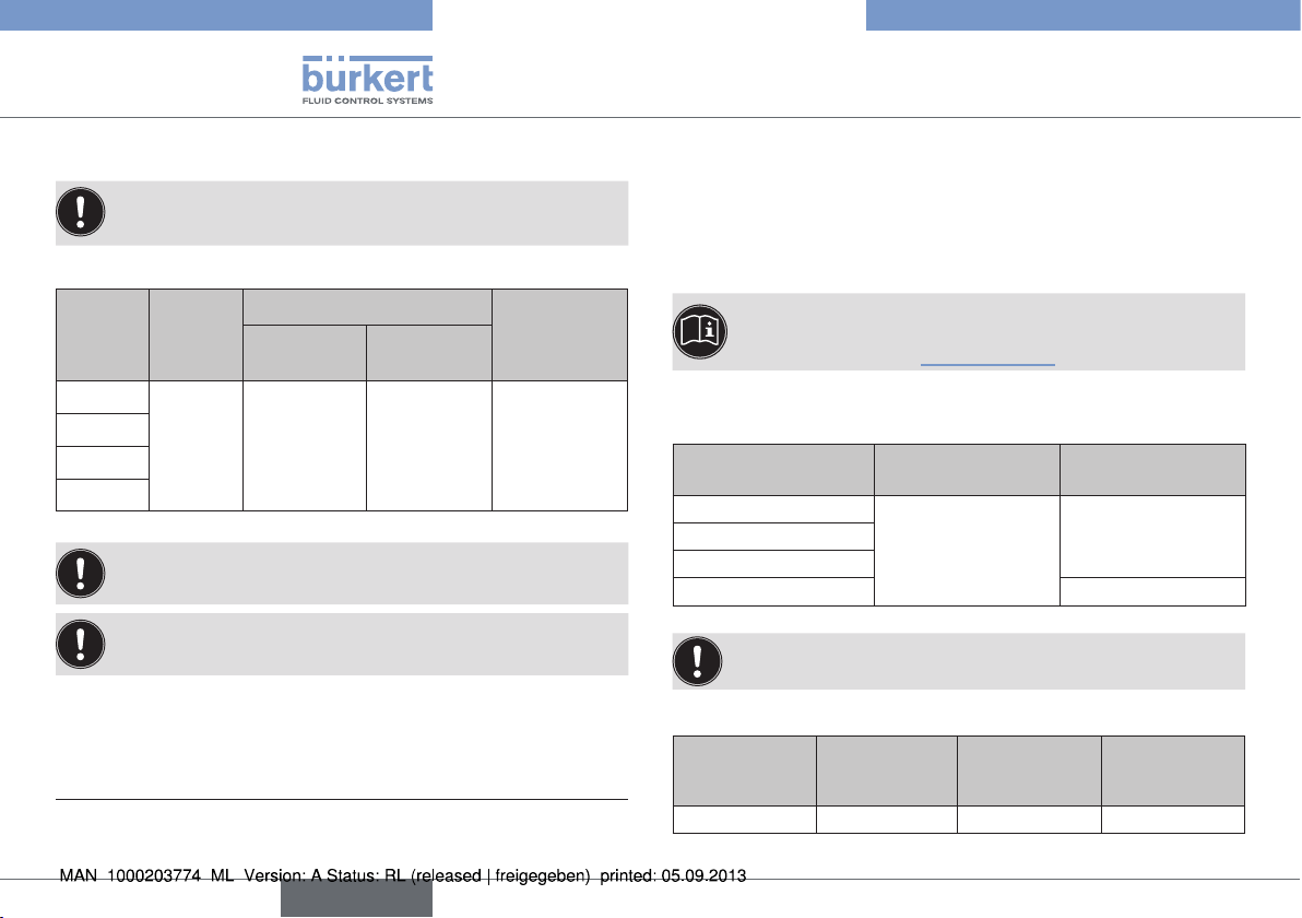
8.2.1. Preparatory work
→ Clean pipelines (Sealing material, swarf, etc.).
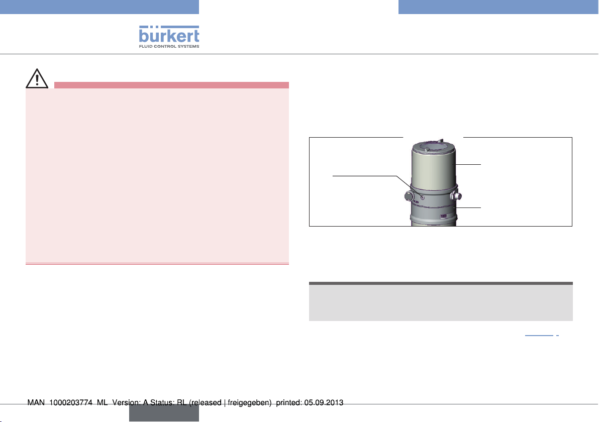
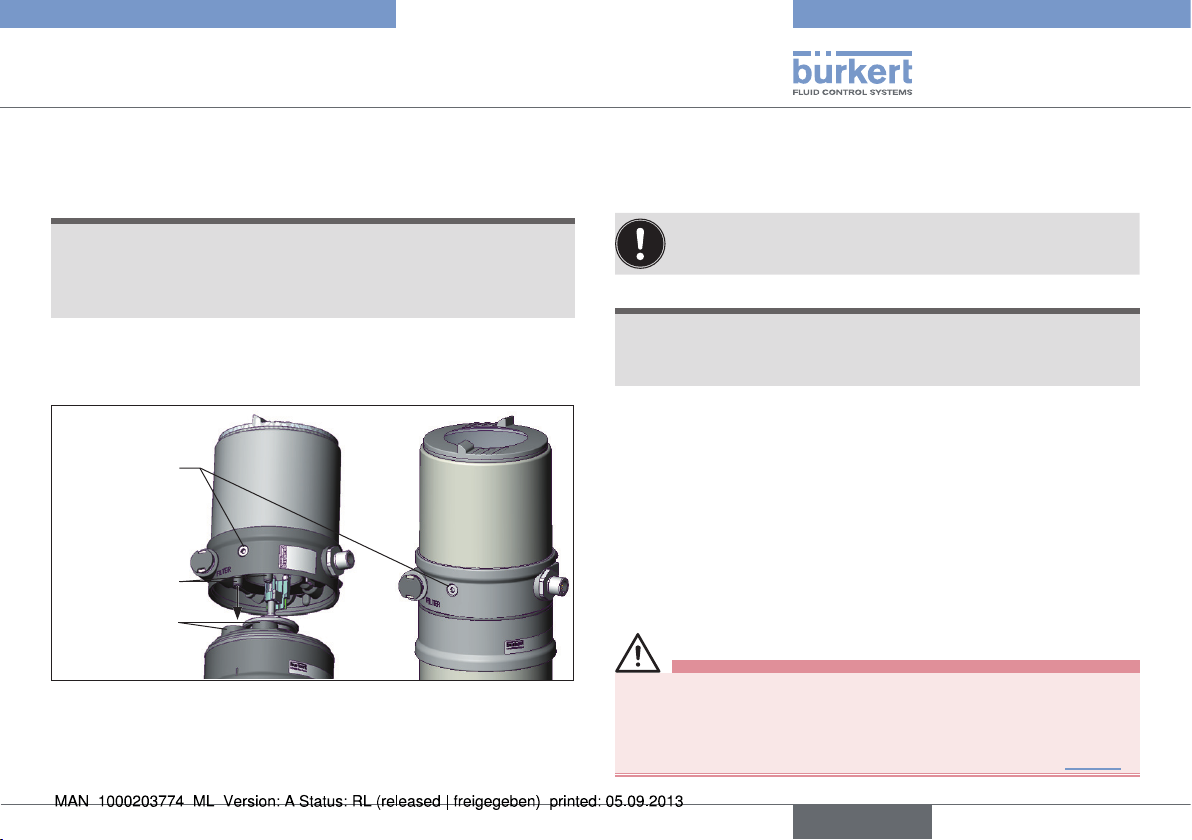
Devices with welded body
Remove the control unit from the actuator (if present):
→ Clamp the valve body in a holding device.
→ Loosen the fastening screws (2x).
→ Remove the control unit upwards.
Fastening
screw (2x)
Fig. 2: Disassembly the control unit
Remove the actuator from the valve body.
Control unit
Actuator
→ Install collet (white grommet) in pilot air port 1.
NOTE!
Damage to the seat seal or the seat contour!
• When removing the actuator, ensure that the valve is in open
position.
→ Control function A pressurize the pilot air port 1(see “Fig. 3”)
with compressed air (5 bar): valve opens.
→ Using a suitable open-end wrench, place the wrench flat on the
pipe.
→ Unscrew the actuator from the valve body.
10
english
Typ 2300
Technical data
Exhaust air port
CFA, CFB
Pilot air port CFI
Pilot air port
CFA, CFB, CFI
Flats for open-end
wrench
Valve body
Fig. 3: Installation
Other device versions
2
1
Install collet:
Actuator
Nipple
→ Do not remove actuator unless this is a customer-specific
requirement.
→ Procedure see “Devices with welded body”.
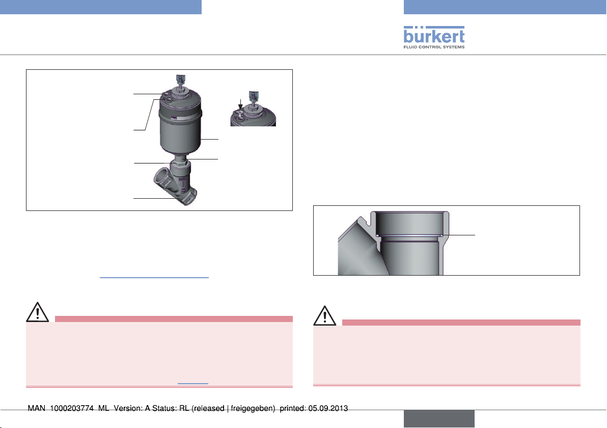
8.3. Installation
WARNING!
Risk of injury from improper installation!
Assembly with unsuitable tools or non-observance of the tightening torque is dangerous as the device may be damaged.
• For installation use an open-end wrench, never a pipe wrench.
• Observe the tightening torque (see “Tab. 5”).
Dirt trap for devices with authorisation in acc. with DIN EN 161
In accordance with DIN EN 161 “Automatic shut-off valves for gas
burners and gas appliances” a dirt trap must be connected upstream
of the valve and prevent the insertion of a 1 mm plug gauge.
8.3.1. Installation of the valve body
Welded bodies
→ Weld valve body in pipeline system.
Other body versions
→ Connect body to pipeline.
8.3.2. Install actuator (welded body)
Graphite seal
Fig. 4: Graphite seal
→ Check the graphite seal and if required, replace it.
WARNING!
Danger if incorrect lubricants used!
Unsuitable lubricant may contaminate the medium. In oxygen applications there is a risk of an explosion!
• In specific applications, e.g. oxygen or analysis applications, use
appropriately authorized lubricants only.
english
11
Typ 2300
Technical data
→ Grease nipple thread before re-installing the actuator (e.g. with
Klüber paste UH1 96-402 from Klüber).
NOTE!
Damage to the seat seal or the seat contour!
• When installing the actuator, ensure that the valve is in open
position.
→ Control function A pressurize the pilot air port 1 (see “Fig. 3”)
with compressed air (5 bar): valve opens.
→ Screw actuator into the valve body. Observe tightening torque
(see “Tab. 5”).
Tightening torques of valve body / nipples
DN Tightening torques [Nm]
15 45 ±3
20 50 ±3
25 60 ±3
32/40 65 ±3
50 70 ±3
65 100 ±3
Tab. 5: Tightening torques of valve body / nipples
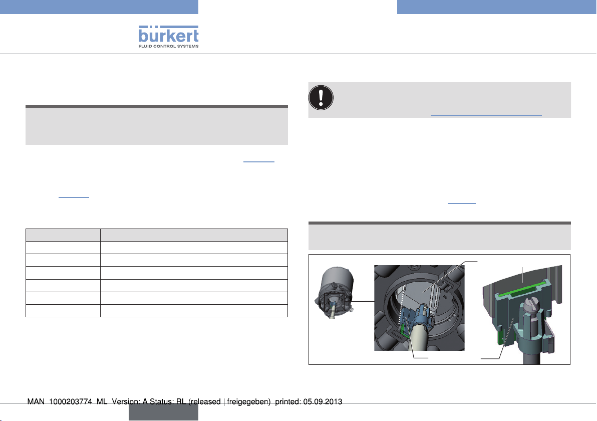
8.3.3. Install control unit
Before installation, check the position of the ports on the
control unit and, if required, align the actuator.
Description see chapter “8.3.4. Rotating the actuator”.
→ Remove collet from pilot air port 1.
→ Check that the O-rings are correctly positioned in the pilot air ports.
→ Align the puck holder and the control unit until
1. the puck holder can be inserted into the guide rail of the
control unit and
2. the supports of the control unit can be inserted into the pilot
air ports of the actuator (see “Fig. 5”).
NOTE!
Damaged printed circuit board or malfunction!
• Ensure that the puck holder is situated flat on the guide rail.
Guide rail
Puck holder
Fig. 5: Aligning the puck holder
12
english
Typ 2300
Technical data
→ Push the control unit, without turning it, onto the actuator until no
gap is visible on the form seal.
NOTE!
Too high torque when screwing in the fastening screw does
not ensure protection class IP65 / IP67!
• The fastening screws may be tightened to a maximum torque of
0.5 Nm only.
→ Attach the control unit to the actuator using the two side fas-
tening screws. In doing so, tighten the screws only hand-tight
(max. torque: 0.5 Nm).
Fastening
screws max.
0.5 Nm
Supports
Pilot air ports
actuator
Fig. 6: Install control unit
8.3.4. Rotating the actuator
The position of the connections can be aligned steplessly by rotating
the actuator through 360°.
Only the entire actuator can be rotated. The control unit
cannot be rotated contrary to the actuator.
NOTE!
Damage to the seat seal or the seat contour!
• When rotating the actuator, ensure that the valve is in open
position.
Procedure:
→ Clamp the valve body in a holding device (applies only to valves
which have not yet been installed).
→ Control function A:
Without unit control: pressurize the pilot air port 1 with compressed air (5 bar): valve opens.
With unit control: open the valve according to the operating
instructions for the control unit.
→ Counter on the flats of the nipple with a suitable open-end
wrench.
WARNING!
Risk of injury from discharge of medium and pressure!
If the direction of rotation is wrong, the body interface may become
detached.
• Rotate the actuator module in the specified direction only (“Fig. 7”)!
english
13

Typ 2300
Technical data
→ Place suitable open-end wrench on the hexagon of the actuator.
→ Rotate counter-clockwise (as seen from below) to bring the
actuator into the required position.
Open-end wrench
Fig. 7: Rotating with open-end wrench
8.4. Pneumatic connection
DANGER!
Danger – high pressure in the equipment!
• Before loosening the lines and valves, turn off the pressure and
vent the lines.
WARNING!
For control function I – Danger if pilot pressure fails!
For control function I control and resetting occur pneumatically.
If the pressure fails, no defined position is reached.
• To ensure a controlled restart, first pressurize the device with pilot
pressure, then switch on the medium.
Risk of injury from unsuitable connection hoses!
Hoses which cannot withstand the pressure and temperature
range may result in hazardous situations.
• Use only hoses which are authorized for the indicated pressure
and temperature range.
• Observe the data sheet specifications from the hose
manufacturers.
The pneumatic connection of the angle-seat control valve
can be carried out only in connection with the appropriate
control unit.
Possible control units are:
Positioner Type 8692, 8694, 8696 and 8792;
Process controller Type 8693 and 8793.
8.4.1. Connection of the control medium
→ Connect the control medium to the pilot air port (“Fig. 8”: 1)
(3 – 7 bar; instrument air, free of oil, water and dust).
→ Fit the exhaust line or a silencer to the exhaust air port (“Fig. 8”:
3) and, if available, to the additional exhaust air port (“Fig. 8”: 3.1).
If used in an aggressive environment, we recommend
conveying all free pneumatic connections into a neutral
atmosphere with the aid of a pneumatic hose.
14
english
 Loading...